US7105982B1 - System for optimal energy harvesting and storage from an electromechanical transducer - Google Patents
System for optimal energy harvesting and storage from an electromechanical transducerDownload PDFInfo
- Publication number
- US7105982B1 US7105982B1US10/811,311US81131104AUS7105982B1US 7105982 B1US7105982 B1US 7105982B1US 81131104 AUS81131104 AUS 81131104AUS 7105982 B1US7105982 B1US 7105982B1
- Authority
- US
- United States
- Prior art keywords
- energy
- storage element
- controlled
- voltage value
- transducer
- Prior art date
- Legal status (The legal status is an assumption and is not a legal conclusion. Google has not performed a legal analysis and makes no representation as to the accuracy of the status listed.)
- Expired - Lifetime, expires
Links
- 238000003306harvestingMethods0.000titleclaimsabstractdescription26
- 238000006243chemical reactionMethods0.000claimsabstractdescription58
- 238000000034methodMethods0.000claimsabstractdescription27
- 239000003990capacitorSubstances0.000claimsdescription41
- 238000012546transferMethods0.000claimsdescription20
- 230000005284excitationEffects0.000claimsdescription8
- 230000003213activating effectEffects0.000claimsdescription2
- 230000008569processEffects0.000abstractdescription9
- 238000006073displacement reactionMethods0.000abstractdescription2
- 238000010586diagramMethods0.000description5
- 230000008901benefitEffects0.000description4
- 238000004146energy storageMethods0.000description4
- 239000000463materialSubstances0.000description4
- 239000000919ceramicSubstances0.000description3
- 238000005516engineering processMethods0.000description3
- 229920000642polymerPolymers0.000description3
- 230000001105regulatory effectEffects0.000description3
- 230000004913activationEffects0.000description2
- 230000003750conditioning effectEffects0.000description2
- 230000001276controlling effectEffects0.000description2
- 238000013461designMethods0.000description2
- 238000012544monitoring processMethods0.000description2
- 230000003071parasitic effectEffects0.000description2
- 230000000737periodic effectEffects0.000description2
- 230000001960triggered effectEffects0.000description2
- 239000011149active materialSubstances0.000description1
- 238000013459approachMethods0.000description1
- 230000002238attenuated effectEffects0.000description1
- 230000005540biological transmissionEffects0.000description1
- 230000015556catabolic processEffects0.000description1
- 230000008859changeEffects0.000description1
- 230000000052comparative effectEffects0.000description1
- 239000002131composite materialSubstances0.000description1
- 230000002596correlated effectEffects0.000description1
- 230000008878couplingEffects0.000description1
- 238000010168coupling processMethods0.000description1
- 238000005859coupling reactionMethods0.000description1
- 230000006735deficitEffects0.000description1
- 238000007599dischargingMethods0.000description1
- 230000000694effectsEffects0.000description1
- 239000011263electroactive materialSubstances0.000description1
- 230000001747exhibiting effectEffects0.000description1
- 238000000605extractionMethods0.000description1
- 238000009434installationMethods0.000description1
- 238000012423maintenanceMethods0.000description1
- 238000005259measurementMethods0.000description1
- 230000002085persistent effectEffects0.000description1
- 238000010248power generationMethods0.000description1
- 238000012545processingMethods0.000description1
- 230000001172regenerating effectEffects0.000description1
- 230000003252repetitive effectEffects0.000description1
- 230000002441reversible effectEffects0.000description1
- 230000008054signal transmissionEffects0.000description1
- 238000002560therapeutic procedureMethods0.000description1
Images


Classifications
- H—ELECTRICITY
- H02—GENERATION; CONVERSION OR DISTRIBUTION OF ELECTRIC POWER
- H02N—ELECTRIC MACHINES NOT OTHERWISE PROVIDED FOR
- H02N2/00—Electric machines in general using piezoelectric effect, electrostriction or magnetostriction
- H02N2/18—Electric machines in general using piezoelectric effect, electrostriction or magnetostriction producing electrical output from mechanical input, e.g. generators
- H02N2/181—Circuits; Control arrangements or methods
Definitions
- the inventionrelates to systems and techniques for optimally harvesting, storing and transferring power generated by mechanical disturbances to an electrical load.
- Harvesting energy from intermittent mechanical disturbancescan be of great value for powering remote sensors and other types of electrical circuits such as those supporting wireless transponders. Even if the available disturbances are relatively minor and produce only very small amounts of energy, the sum total of energy collected over time can be enormous benefit for a wide variety of applications.
- Energy harvesting transducers and energy storage circuitrycan effectively provide “self powering circuits” that are far more robust and longer lived than ones powered by a storage battery or can enable hybrid systems with reduced size batteries. These self powered circuits can draw and store energy from mechanical disturbances in the environment around them. This enables them to operate in environments where regular maintenance, to change batteries for example, might be impractical or impossible.
- the harvested electrical powercan be used to provide power for a wide variety of applications such as powering of remote sensors, transmitting telemetry data over a wireless link, local alarm indication, implanted electronic medical devices for therapy or monitoring, and many other uses.
- the present inventiondifferentiates itself from the prior art because it proposes a system and electrical circuit that can be used to efficiently harvest, store and transfer power from mechanical disturbances, and then apply that power to an application circuit under a variety of load conditions.
- An additional aspect of this inventionis the ability to accomplish this based entirely on the energy supplied by the disturbance itself, i.e. with no external power supply needed for the control circuitry.
- the present inventionis a circuit that optimally collects and stores energy from a mechanical disturbance for use by an electrical load.
- the voltage range that is optimal for collecting energy from an electromechanical transduceris not compatible with the requirements of low power circuit loads. The invention seeks to ensure that these requirements are met.
- an electromechanical transducerconverts mechanical energy in the form of forces and displacements into electrical energy in the form of voltage and charges.
- One particular type of electromechanical transduceris an electromagnetic coil and moving magnet.
- Another type of electromechanical transduceris a piezoelectric transducer, here generally referring to a broad class of metallic, ceramic and polymer electro and magneto-active materials capable of converting electrical energy into mechanical energy or vice versa.
- Such materialsare commonly available piezoelectric ceramics, piezoelectric composites and polymers, electrostrictive ceramics and polymers as well as magnetostrictive materials and other materials in which the mechanical, electrical and/or magnetic fields exist within the transducer materials and are coupled therein.
- the voltage outputs for piezo transducerscould be in the range of 20 to 100 Volts while low voltage circuits may only require voltages only in the 2 to 15 volt range. Since the average power generated by transducers can be small, on the order of hundreds of microwatts, the available power to operate the switching and conversion functions can be very limited.
- the disturbancemay have many characteristics including but not limited to variable amplitude of timing.
- the disturbancecan consist of a force pulse with constant peak amplitude but whose timing between pulses is not predefined or regular. It can also consist of a continuous excitation waveform of varying amplitude.
- a key aspect of this inventionis to create a system that can optimize mechanical to electrical power conversion in the face of intermittent or varying disturbances.
- the loadmay require a substantially greater amount of power, in the milli-watt to watt range, to operate, (for example) in a burst mode for wireless signal transmission.
- the circuitdoes this by harvesting and storing the electrical power generated from the mechanical disturbances in a manner that is optimal for the transducer (maximizing power flow from the disturbance into the electrical domain), and then switch transforms and delivers power to the load application electronics in a manner that is optimal for the given load.
- a principal element of this inventionis therefore the ability to optimize this power conversion process using intelligent control of the high voltage to low voltage conversion process by, for instance, sensing the disturbance with an external sensor or sensing an internal voltage of the system, and then using this information to control when and how the electrical conversion process should occur.
- this functionis performed by a controlled conversion element.
- the preferred embodiment of the inventionincludes an electromechanical transducer, a power rectification element, an input storage element, an internally or eternally controlled switch together with a DC—DC converter element (together a controlled conversion element), and an output energy storage element.
- the transducertransforms mechanical disturbances into electrical AC power which is rectified into DC power and accumulated and stored in an input storage element.
- the controlled converterholds the voltage applied to the input storage element to within a predetermined range that is optimal for harvesting energy from the transducer.
- the voltage rangecan be hardwired into the circuit or controllably adjusted to best match a given disturbance characteristic.
- the predetermined optimum rangeis such that the voltage is not allowed to approach an open circuit peak voltage.
- a center point of the controlled voltage rangecan be set to be about one-half of the peak open-circuit voltage of the energy signal supplied by the transducer.
- the smart converterWhen the voltage is within the optimal range for a given disturbance, the smart converter then, and only then, enables a DC—DC converter to convert this stored energy to a voltage that is usable by the load circuit. At this point, the energy is stored in an output power storage element for use by the application electronics.
- the output storage elementcan be a capacitor or battery type element. The controlled conversion process thus runs discontinuously, in such a manner to approximately optimize power transfer from the transducer.
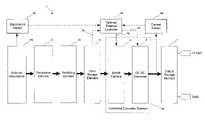
- FIG. 1is a block diagram showing a disturbance, and components of the invention including a transducer, rectifier, input storage capacitor, controlled converter, output storage, and optional external control sensors and circuitry.
- FIG. 2is a more detailed block diagram of the invention showing the transducer, rectification and input energy storage elements.
- FIG. 3is a graph of time histories of mechanical transducer strain and transducer voltage functions (in the open circuit condition).
- FIG. 4is a schematic of a preferred embodiment of the system with a self-powered controlled conversion element.
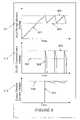
- FIG. 5is a graph showing relationship between transducer power generation as a function of the input storage capacitor voltage.
- FIG. 6is a graph of the time histories of the input storage voltage, converter input voltage and output storage voltages.
- FIG. 7is a detailed diagram of a Direct Current to Direct Current (DC—DC) converter.
- the inventionrelates to an electrical circuit for optimally harvesting, storing and transferring power generated by mechanical disturbances to an electrical load.
- the power harvesting circuitefficiently collects and stores energy from mechanical disturbances in an input storage element. The accumulated energy is then converted using a controlled DC—DC converter to the optimal voltage level for the load electronics.
- the circuit inventionthus accumulates and stores energy in the optimal voltage range of the transducer, while delivering the energy at the optimal voltage for the final load at the optimal output voltage.
- FIG. 1A block diagram of one embodiment of the invention is shown in FIG. 1 .
- the circuit 1is coupled to consists of a mechanical disturbance 8 b , and included a electromechanical (possibly piezoelectric) transducer 2 , a rectifying bridge made up of diodes 3 a , an input storage element 4 , a controlled conversion element 8 e which in one embodiment can consist of a switch element 5 and a DC—DC converter 6 which is activated when electrical energy is presented to it, and an output storage element 7 .
- the circuit 1transforms mechanical disturbances into usable power for an electric circuit.
- the piezo transducer 2converts the mechanical disturbances 8 b into electrical signals;
- the mechanical disturbancescan be of a periodic or intermittent nature and can have waveforms of arbitrary time history and amplitude.
- the disturbancescan consist of a string of irregularly spaced (possibly intermittent) but constant amplitude force or deflection inputs onto the transducer, or the disturbance can consist of a persistent excitation of possibly slowly varying amplitude. It is the intent of this invention to provide a self powered circuit which can maximize mechanical to electrical power conversion under a broad range of input disturbance time histories.
- circuit 1There are two separate parts to the circuit 1 for energy harvesting and storage. One part involves the transfer of energy from the transducer element 2 to the input storage element 4 , and the other part involves conversion of that stored energy to some lower voltage (or optionally higher voltage) using the controlled conversion element 8 e .
- this second partpotentially consists of a voltage sensing switch ( 5 ) and DC–DC converter 6 . The energy out of the DC—DC converter 6 is then stored in the output storage element 7 for use by an application load circuit (not shown in the drawings).
- a key aspect of the inventionis the ability to maximize the energy flow from the mechanical disturbance to the load. This is done by keeping the input storage element 4 (specifically, the signal applied thereto) at or near a voltage level which maximizes power transfer from the transducer through the rectifier to the input storage element.
- the inputis a time signal whose non-steady component is a given amplitude
- this maximum power transfertypically occurs when the input storage element is maintained at a voltage level which is about one-half of the peak non-steady voltage amplitude (Vmax) 305 about the mean 306 that would appear on the transducer (under that excitation) if no extraction circuitry were connected (the open circuit voltage).
- Vmaxpeak non-steady voltage amplitude
- Non-idealitiesmay push the optimum level slightly off of this value.
- Direct techniquesmeasure, sense or otherwise determine the voltage level on the input storage element and control to a optimal voltage level or range, shown in FIG. 5 as 410 .
- This optimal rangediscussed in detail below, can be hardwired into the electronics by, for instance, component choices (good when the amplitude is well known) or can be determined from an external controller 8 a in the case that the amplitudes are not well known.
- Indirect systemsmeasure something besides the input storage element voltage, for instance, average current into the output storage element using a current sensor 8 d (proportional to output power delivered to a load), and then control to optimize this alternate objective, indirectly maintaining the input storage element at the optimal voltage level.
- the primary controlling elementis a controlled conversion element 8 e .
- This controlled conversion elementoperates under external or internal control so as to maintain the input storage element within its optimal voltage range.
- external sensor elements8 c , 8 d and 8 f
- control element 8 apotentially a very low power microprocessor
- These control signals8 g and 8 h
- the core function of the controlwill be to optimize power flow into the input storage element by choosing the right voltage levels for a given disturbance.
- an external sensor of the disturbance 8 cfor instance an accelerometer or strain sensor or other mechanical sensor which can be correlated to disturbance amplitude, can be used by the external control element 8 a to determine the preset optimal voltage levels for a given disturbance sensor signal using an internally stored look up table.
- the look up tablecan be pre-entered into the controller or derived from calibration of the system after installation.
- These predetermined optimal levelscan be provided to the controlled conversion element 8 e or used as input into a servo loop which drives the input storage voltage to that value by intermittently activating the down conversion from the input storage to the output storage through control signals to either the controlled conversion element 8 e or the switch 5 or DC—DC converter 6 through the control signals, 8 g and 8 h .
- This intermittent activationfor instance varying the “on” duty cycle of the DC—DC converter, can be used to maintain the input storage voltage to the external controller provided optimal levels.
- Information provided to the external controller 8 acan come from alternate sensors, for instance current sensors on the output storage element 8 d (measuring current into the storage element and therefore measuring electrical power into the output storage element), or voltage sensors at different places on the circuit, for example sensors measuring the voltage at the input storage element 8 f .
- caremust be taken to reduce leakage through the sensing circuitry. This can be done by using a switch structure similar to that of element 5 which can be used to controllably connect the sensor signal to the sensor circuitry only when it is sampled or enabled, leaving it unconnected most of the time and thereby limiting leakage.
- the controller 8 acan periodically turn off the down conversion process to let the input storage element rise to the open circuit voltage level associated with the current state of the input disturbance.
- the voltagecan be sampled as above and determined; the external controller can control the controlled conversion element to drive the input storage element to one-half of that open circuit voltage, V max , 305 . In this way the controller can determine the disturbance amplitude and adjust to it on a periodic basis.
- the external controller 8 acan allow the controlled conversion element 8 e to respond to other needs of the application electronics. For instance, when a critical message is to be sent and extra power is needed for the transmission, the controlled conversion element can be commanded to completely drain the input storage element rather than maintain it at the optimal power harvesting levels.
- FIG. 2shows the details of the piezo transducer 2 , the rectification bridge 3 a made up of a set of diodes, the input storage element 4 and the output storage element 7 .
- the transducer element 2is a piezoelectric transducer, although other electro active materials or electromechanical transducers exhibiting electromechanical coupling can be substituted.
- Rectification elementis made up of four diodes 3 b , 3 c , 3 d and 3 e .
- other rectification schemessuch as a half wave rectifier or voltage doubling rectifier as known in the art can be used interchangeably. These can affect the value of the optimal voltage range for the input storage element. For instance in the case of a voltage doubling rectifier, the optimal voltage for the input storage device will be double what it would be for the full wave rectifier.
- the input storage device 4is a low leakage capacitor; the output storage device 7 is also a low leakage capacitor but can be a battery or other electrical storage device.
- FIG. 3shows a version of the controlled conversion element in more detail.
- itshows the circuitry for implementing an internally controlled controlled conversion element 5 and 6 .
- Thisincludes a voltage sensing switch 5 as well as a DC–DC converter 6 which operates only when power is presented to its input terminals.
- FIG. 3thus shows an example of a design in which the optimal voltage levels have been preset into the values of Zener Diodes 10 and 11 .
- the switch 13can be externally controlled by a signal 8 g .
- the voltage sensing switch 5consists of a pair of Zener diodes 10 and 11 which determine the high and low voltage operating switching points respectively, for transistors 13 , 20 and 21 , which together operate to activate the switch, various bias resistors 14 , 15 , 16 , 17 and 18 , shunt capacitor 12 and diode 19 to control current flow.
- Voltage and current signals from the transducer 2typically consist of waveforms with time varying and steady components.
- FIG. 4shows one example of a typical time relationship between the mechanical input to a transducer 301 and the transducer output voltage 302 .
- the mechanical excitation signals 301can have varying amplitude 303 or intermittent or varying timing. In general it can be an arbitrary forcing waveform with mean and time varying components.
- the voltage on the storage capacitor 4is constrained to a range 406 centered around the optimum value so that the electromechanical transducer 2 always sees the optimum load voltage and therefore achieves the maximum power throughput.
- the optimal low range V LOW 402 and the optimal high voltage range V HIGH 403which can be determined by circuit theory, are also shown. They are generally chosen so that the input storage element is constrained to operate near but not exactly at the optimal voltage. Broadening the range allows less efficient energy transfers to the input storage element (greater variation in power to the input storage element, 410 ) but allows more tolerance to varying disturbance amplitudes. In the preferred embodiment, this range is between 5–40% of V max .
- the transfer of voltage to the DC—DC converter 6is halted until the voltage builds up back within the optimal range 406 .
- the DC—DC converteris connected to be self-bootstrapping as it is powered by the output of the voltage server switch. Thus, the DC—DC converter stops running when the switch opens and consumes no more power.
- the switchis again turned on an voltage is presented to the DC—DC converter which then draws power out of the input storage element and converts it to low voltage at the output storage element.
- the rangecan be made programmable responding to sensor input of the disturbance level or condition.
- the optimal voltage level and range for the input storage capacitorcan be determined by feed-forward or feedback means to optimize delivered power to the output storage element in varying disturbance conditions.
- four diodes 3 b , 3 c , 3 d , and 3 erectify the AC waveform to produce pulses of current that charge the storage capacitor 4 in quantum steps.
- FIG. 7is a more detailed circuit diagram of the DC—DC converter 6 .
- switch device U 1 700When power is applied to an input terminal 712 of the DC/DC converter 6 , switch device U 1 700 automatically starts operation.
- This switch 700is part of a standard forward, or buck converter that converts the energy stored in energy storage element to a regulated voltage output 707 .
- U 1 700is typically an electrical circuit similar to a TNY-253 and switches to provide a quasi-square wave at high frequency with a duty cycle dictated by the ratio of output voltage 707 to the input voltage 712 .
- U 1 700Internal to U 1 700 are FET drain and source connections (shown as ‘D’ and ‘S’, respectively) and a control circuit.
- DFET drain and source connections
- L 1 705When the FET turns on, energy is stored in L 1 705 .
- D 8 708When the FET turns off, the magnetic field in L 1 705 forces the current to continue flowing, but through D 8 708 instead of the FET. By this repetitive action, energy is transferred to the output capacitor (C 4 ) 709 .
- All diodes 703 and 708 shownare designed to have very low leakage currents.
- U 3 711is a precision shunt regulator configured as a reference.
- the cathode current of U 3 7111increases rapidly, turning on the optocoupler, U 2 701 with light 702 generated by light emitting diode D 9 703 .
- the circuit 6therefore operates in burst mode, supplying power pulses when required by the load connected to the output 707 .
- Each switching cycleoperates in discontinuous current mode as well, i.e. the current in L 1 705 ramps down to zero before the next switching cycle begins.
- the low power voltage sensing switch 5then performs two functions. The first is to monitor and keep the voltage on the capacitor 7 within a range that is optimal for the transfer of energy from the piezo transducer 2 to the storage capacitor 4 . The second is to switch the energy between the storage capacitor and the load. When the voltage on the storage capacitor 4 drops to below a predetermined optimal value, then the voltage sensing switch 5 shuts off the flow of energy until the voltage on the capacitor 4 builds back up to the optimal level. If the voltage on the capacitor 4 rises above the optimal range, the switch will turn on and initiate the DC—DC conversion process dumping charge to the output storage element. If this element is at capacity and can accept no further charge then the DC—DC converter is inhibited and the voltage sensing switch 5 will thus clamp the output voltage at the top of the optimal range.
- the load circuitry power requirementswill be designed to periodically use the stored energy while it is in the optimal range.
- the load circuitcan lie un-powered in a dormant or suspended state until sufficient energy has been built up to power the circuitry in a burst mode where the load continuously draws power until the voltage on the storage capacitor drops to below the optimal range and the power to the circuit is shut off until the energy has again built up to predetermined level. This insures that the energy is harvested and stored optimally independent of the demands of a load circuit. In either mode of use, the circuit invention will optimally transfer power from the mechanical disturbances into useable energy.
- the voltage sensing switch circuit 5transfers energy from the input storage capacitor 4 in an efficient method to the DC—DC converter 6 with minimum loss of energy through leakage and other parasitic losses. This is important since the very low power produced by most piezo transducers would be lost, or severely attenuated, if it is not optimally harvested, stored and transferred to the load.
- the voltage sensing switch 5only transfers energy from the storage capacitor 4 to the DC—DC converter 6 when the voltage across the capacitor 4 is in an optimal range for power transfer from the piezo transducer 2 .
- the DC—DC converter 6thus converts the voltage from the level that is optimal from the energy harvesting transducer to a level that is optimal for the desired load circuit.
- Current out of the DC—DC converter 6is stored in the output storage capacitor 7 .
- Power drawn from the output storage element 7can be used to power the load circuitry as well as the optional external control sensors, sensor conditioning electronics and control processing ( 8 a , 8 d , 8 c , 8 f , 8 g ) creating a self powered system operating entirely off of power derived from the disturbance. In the system shown in FIG. 3 without external control, the controlled conversion under internal control is entirely powered from energy derived from the disturbance.
- the DC—DC 6 converterWhen voltage sensing switch 5 is switched on, the DC—DC 6 converter automatically starts operation using self bootstrapping techniques known in the art. Energy from the DC—DC converter is then stored in an output capacitor 7 ; the circuit output voltage 510 is regulated by the DC—DC converter 6 when the voltage sensitive switch 5 and DC—DC converter 6 are on. When the DC—DC converter 8 is turned off by the voltage sensing switch 5 , the output storage capacitor 7 continues to supply energy to the load with voltage droop as shown in FIG. 5 . When sufficient energy has been collected by the input storage capacitor 4 the voltage selective switch 5 and DC—DC converter 6 are again activated and process repeats as shown in FIG. 5 .
- the circuit 1mitigates the effects of leakage by design and component selection. Because the average continuous power flow from the transducer 2 can be so small (on the order of hundreds of microwatts, typically) there is little available power to operate the switch 5 by monitoring the voltage on the storage capacitor 3 and make a decision to switch on the converter 6 to convert energy from the storage capacitor 4 to the selected output voltage 7 . It is not typically practical to harvest the piezo transducer 2 power on a continuous basis. This is due to the fact that the DC—DC converters 6 cannot operate directly off the relatively small amount of power generated by the piezo transducer 2 , since the quiescent power losses greatly exceed the power available. Therefore the DC–DC converter is operated in discontinuous mode, only when triggered by the activation of the switch 9 in the critical input storage element voltage range. When voltage is presented to the input of the DC—DC conversion element, it is powered off of this voltage and initiates the power transfer.
- This discontinuous operation, triggered by the voltage threshold event,is important to accommodate situations where there can be considerable time between disturbance excitations.
- the systemthus does not rely on a steady disturbance level, but only on the amount of eventual accumulated power to trigger the DC—DC conversion. This allows there to be long periods of comparative inactivity in which no quiescent power is dissipated. This ability to weather disturbance droughts is important for micro-power systems.
- This circuitis also required to store very small energy pulses over a relatively long time, in a low-leakage storage capacitor 4 , and then periodically discharge that capacitor 4 into a load (at a substantially higher rate perhaps 1 to 3 watts) whose voltage is typically much lower than the optimum load for the piezo transducer 2 to generate its optimum power.
- the electronic low loss voltage switch 5 required to keep the voltage on the storage capacitor within a narrow rangeuses a pair of zener diodes 9 and 11 that control transistor switches 9 B shown in schematic of FIG. 4 .
- Zener diodes in the high voltage range(90–100 volts) are typically required to optimally harvest power from the piezo transducer, and typically have very low leakage, and drain negligible energy from the storage capacitor 4 .
Landscapes
- Dc-Dc Converters (AREA)
Abstract
Description
Claims (27)
Priority Applications (1)
| Application Number | Priority Date | Filing Date | Title |
|---|---|---|---|
| US10/811,311US7105982B1 (en) | 2003-03-26 | 2004-03-26 | System for optimal energy harvesting and storage from an electromechanical transducer |
Applications Claiming Priority (2)
| Application Number | Priority Date | Filing Date | Title |
|---|---|---|---|
| US45802503P | 2003-03-26 | 2003-03-26 | |
| US10/811,311US7105982B1 (en) | 2003-03-26 | 2004-03-26 | System for optimal energy harvesting and storage from an electromechanical transducer |
Publications (1)
| Publication Number | Publication Date |
|---|---|
| US7105982B1true US7105982B1 (en) | 2006-09-12 |
Family
ID=36951782
Family Applications (1)
| Application Number | Title | Priority Date | Filing Date |
|---|---|---|---|
| US10/811,311Expired - LifetimeUS7105982B1 (en) | 2003-03-26 | 2004-03-26 | System for optimal energy harvesting and storage from an electromechanical transducer |
Country Status (1)
| Country | Link |
|---|---|
| US (1) | US7105982B1 (en) |
Cited By (53)
| Publication number | Priority date | Publication date | Assignee | Title |
|---|---|---|---|---|
| US20060237968A1 (en)* | 2005-04-20 | 2006-10-26 | Rockwell Scientific Licensing, Llc | High efficiency power converter for energy harvesting devices |
| US20070141874A1 (en)* | 2005-02-17 | 2007-06-21 | General Electric Company | Power control system and method |
| WO2007118277A1 (en)* | 2006-04-18 | 2007-10-25 | Commonwealth Scientific And Industrial Research Organisation | A method and apparatus for harvesting energy from mechanical vibrations |
| US20080097188A1 (en)* | 2006-10-20 | 2008-04-24 | Ellipse Technologies, Inc. | External sensing systems and methods for gastric restriction devices |
| US20080150495A1 (en)* | 2006-11-07 | 2008-06-26 | Potenco, Inc. | Electrical power generator with adaptive coupling |
| US20080150493A1 (en)* | 2006-11-07 | 2008-06-26 | Potenco, Inc. | Gearless human power generation |
| US20080157988A1 (en)* | 2006-12-27 | 2008-07-03 | Industrial Technology Research Institute | Portable partial discharge detection apparatus and method thereof |
| US20080157636A1 (en)* | 2006-11-07 | 2008-07-03 | Potenco, Inc. | Human power generation using dual pulls |
| US20080193740A1 (en)* | 2007-01-31 | 2008-08-14 | Nesbitt Jeffrey E | Composite building material and method for making composite building material |
| US20090085442A1 (en)* | 2007-09-28 | 2009-04-02 | Robert Bosch Gmbh | Passive self-tuning resonator system |
| US20090152986A1 (en)* | 2004-11-17 | 2009-06-18 | Ilan Beery | Piezoelectric power supply |
| DE102007059349A1 (en)* | 2007-12-10 | 2009-07-09 | Siemens Ag | Load adjustment device for power management application specific integrated circuit of micro system, has device such as switch and switching electric rectifier, for reducing medium electric current flowing through electrical consumer |
| US20100081324A1 (en)* | 2007-09-24 | 2010-04-01 | John Mezzalingua Associates, Inc. | Coaxial cable connector with an internal coupler and method of use thereof |
| US7732974B1 (en) | 2006-11-15 | 2010-06-08 | Justin Boland | Electrostatic power generator cell and method of manufacture |
| US20100178806A1 (en)* | 2007-09-24 | 2010-07-15 | John Mezzalingua Associates, Inc. | Coaxial cable connector with an external sensor and method of use thereof |
| US20100194382A1 (en)* | 2007-09-24 | 2010-08-05 | John Mezzalingua Associates, Inc. | Method for determining electrical power signal levels in a transmission system |
| US20100206071A1 (en)* | 2009-02-17 | 2010-08-19 | Robert Bosch Gmbh | Drive frequency tunable mems gyroscope |
| US20100253088A1 (en)* | 2009-03-09 | 2010-10-07 | Miw Associates, Llc | Energy generator |
| US20110074388A1 (en)* | 2008-11-17 | 2011-03-31 | Rochester Institute Of Technology | Embedded coupler device and method of use thereoff |
| US20110077884A1 (en)* | 2008-11-17 | 2011-03-31 | Rochester Institute Of Technology | Internal coaxial cable connector integrated circuit and method of use thereof |
| US20110080057A1 (en)* | 2008-11-17 | 2011-04-07 | Rochester Institute Of Technology | Power harvesting device and method of use thereof |
| US20110080158A1 (en)* | 2007-09-24 | 2011-04-07 | John Mezzalingua Associates, Inc. | Coaxial cable connector with internal floating ground circuitry and method of use thereof |
| US7948153B1 (en) | 2008-05-14 | 2011-05-24 | Sandia Corporation | Piezoelectric energy harvester having planform-tapered interdigitated beams |
| US20110130034A1 (en)* | 2008-11-17 | 2011-06-02 | John Mezzalingua Associates Inc. | Coaxial connector with integrated molded substrate and method of use thereof |
| WO2011064137A1 (en)* | 2009-11-27 | 2011-06-03 | Hahn-Schickard-Gesellschaft für angewandte Forschung e.V. | Load state determiner, load assembly, power supply circuit and method for determining a load state of an electrical power source |
| US20110161050A1 (en)* | 2009-12-03 | 2011-06-30 | John Mezzalingua Associates, Inc. | Coaxial cable connector parameter monitoring system |
| US20110215590A1 (en)* | 2007-09-18 | 2011-09-08 | University Of Florida Research Foundation, Inc. | Dual-Mode Piezoelectric/Magnetic Vibrational Energy Harvester |
| US20110222419A1 (en)* | 2010-03-12 | 2011-09-15 | Sunrise Micro Devices, Inc. | Power efficient communications |
| US20110237125A1 (en)* | 2007-09-24 | 2011-09-29 | John Mezzalingua Associates, Inc. | Status sensing and reporting interface |
| DE102010042153A1 (en)* | 2010-10-07 | 2012-04-12 | Siemens Aktiengesellschaft | Voltage transformer with at least one electro-mechanically acting switch and corresponding method |
| US20130082657A1 (en)* | 2011-09-30 | 2013-04-04 | Research In Motion Limited | Charging system for a rechargeable power source |
| US8604936B2 (en) | 2010-12-13 | 2013-12-10 | Ppc Broadband, Inc. | Coaxial cable connector, system and method of use thereof |
| EP2132794A4 (en)* | 2007-02-23 | 2014-01-08 | Michelin & Cie | METHOD FOR EVACUATING CAPACITIVE LOADS |
| US20140021825A1 (en)* | 2012-07-23 | 2014-01-23 | Murat Ocalan | Non-stationary multi-frequency vibration energy harvesting with tunable electrical impedance |
| US20140088917A1 (en)* | 2012-09-26 | 2014-03-27 | Stmicroelectronics S.R.L. | Step counter device with energy-scavenging functionality, and step-counting method |
| US8729772B1 (en)* | 2010-12-30 | 2014-05-20 | S&F Sonics | Swept sideband PZT driver circuit |
| US20140209599A1 (en)* | 2013-01-25 | 2014-07-31 | Energyield, Llc | Energy harvesting container |
| US9160223B2 (en) | 2011-04-29 | 2015-10-13 | Stmicroelectronics S.R.L. | Rectifier circuit, and environmental energy harvesting system comprising the rectifier circuit |
| KR20160032395A (en)* | 2014-09-15 | 2016-03-24 | 고려대학교 산학협력단 | Apparatus and method for energy harvesting |
| FR3030157A1 (en)* | 2014-12-15 | 2016-06-17 | Commissariat Energie Atomique | CIRCUIT FOR COMPARING A VOLTAGE AT A THRESHOLD |
| US9385626B2 (en) | 2011-04-29 | 2016-07-05 | Stmicroelectronics S.R.L. | System and method for efficiently harvesting environmental energy |
| US9461504B2 (en) | 2012-09-27 | 2016-10-04 | Stmicroelectronics S.R.L. | Enhanced efficiency energy-scavenging interface, method for operating the energy-scavenging interface, and energy-scavenging system comprising the energy-scavenging interface |
| CN106787592A (en)* | 2016-12-30 | 2017-05-31 | 深圳市无电通科技有限公司 | Impulse generator electric energy synthesizer and its method |
| US9746527B2 (en) | 2011-11-21 | 2017-08-29 | Blackberry Limited | Method and apparatus for battery charge level estimation |
| US9888337B1 (en) | 2015-07-25 | 2018-02-06 | Gary M. Zalewski | Wireless coded communication (WCC) devices with power harvesting power sources for WiFi communication |
| US9911290B1 (en) | 2015-07-25 | 2018-03-06 | Gary M. Zalewski | Wireless coded communication (WCC) devices for tracking retail interactions with goods and association to user accounts |
| US9972190B2 (en) | 2015-12-15 | 2018-05-15 | Stmicroelectronics (Crolles 2) Sas | Event detector |
| US10312797B1 (en)* | 2016-08-29 | 2019-06-04 | The United States Of America As Represented By Secretary Of The Navy | Zero power startup circuit for vibrational energy harvesting |
| EP2622732B1 (en)* | 2009-11-19 | 2019-08-28 | Perpetuum Ltd. | Vibration energy harvester for converting mechanical vibrational energy into electrical energy |
| CN110297449A (en)* | 2015-05-29 | 2019-10-01 | 广东易百珑智能科技有限公司 | Self-generating wireless switch and its application |
| US10806212B2 (en) | 2015-05-29 | 2020-10-20 | Nike, Inc. | Multi-capacitor kinetic energy generator |
| EP3624322A4 (en)* | 2017-05-12 | 2020-12-23 | Beijing Institute of Nanoenergy and Nanosystems | POWER SUPPLY MANAGEMENT MODULE, ADMINISTRATIVE PROCEDURES AND ENERGY SYSTEM FOR A TRIBOELECTRIC NANOGENERATOR |
| US11482949B2 (en)* | 2018-12-03 | 2022-10-25 | Honeywell Federal Manufacturings Technologies, Llc | Electrostatic harvester device |
Citations (20)
| Publication number | Priority date | Publication date | Assignee | Title |
|---|---|---|---|---|
| US4657339A (en) | 1982-02-26 | 1987-04-14 | U.S. Philips Corporation | Fiber optic switch |
| US5177348A (en) | 1991-08-26 | 1993-01-05 | Herzel Laor | Apparatus and method for aligning optical fibers with an array of radiation emitting devices |
| US5450508A (en) | 1994-12-08 | 1995-09-12 | International Business Machines Corporation | Apparatus and method for optical fiber alignment using adaptive feedback control loop |
| US5552656A (en)* | 1995-08-07 | 1996-09-03 | Ocean Power Technologies, Inc. | Self-powered anti-fouling device for watercraft |
| US6137941A (en) | 1998-09-03 | 2000-10-24 | Lucent Technologies, Inc. | Variable optical attenuator |
| WO2000076106A1 (en) | 1999-06-09 | 2000-12-14 | Astarte Fiber Networks, Inc. | Method and apparatus for providing loss equalization and adjustment in a fiber optic network |
| US6222954B1 (en) | 1999-09-17 | 2001-04-24 | Light Bytes, Inc. | Fault-tolerant fiber-optical beam control modules |
| US6263123B1 (en) | 1999-03-12 | 2001-07-17 | Lucent Technologies | Pixellated WDM optical components |
| WO2002001274A2 (en) | 2000-06-28 | 2002-01-03 | Megasense | Optical switch |
| US6345134B1 (en) | 1996-01-17 | 2002-02-05 | Pirelli Cavi E Sistemi S.P.A. | Optical device for compensating the dispersion of optical signals |
| US6411751B1 (en) | 1999-10-08 | 2002-06-25 | Lucent Technologies Inc. | System and method for training an optical cross-connect comprising steerable switching elements |
| US6433465B1 (en)* | 2000-05-02 | 2002-08-13 | The United States Of America As Represented By The Secretary Of The Navy | Energy-harvesting device using electrostrictive polymers |
| US6465931B2 (en)* | 2000-03-29 | 2002-10-15 | Qortek, Inc. | Device and method for driving symmetric load systems |
| US6484114B1 (en) | 2001-08-20 | 2002-11-19 | Glimmerglass Networks, Inc. | Method for calibrating a free-space-coupled fiber-optic transmission system |
| WO2003016980A1 (en) | 2001-08-20 | 2003-02-27 | Glimmerglass Networks, Inc. | Method and apparatus for optical beam power attenuation |
| WO2003016958A2 (en) | 2001-08-20 | 2003-02-27 | Glimmerglass Networks, Inc. | Method and apparatus for optical beam alignment detection and control |
| US20030048984A1 (en) | 2001-09-10 | 2003-03-13 | Ng Eddie Kai Ho | All-optical dynamic gain equalizer |
| US20030137221A1 (en)* | 2002-01-18 | 2003-07-24 | Radziemski Leon J. | Force activated, piezoelectric, electricity generation, storage, conditioning and supply apparatus and methods |
| US20030143963A1 (en)* | 2000-05-24 | 2003-07-31 | Klaus Pistor | Energy self-sufficient radiofrequency transmitter |
| US20040078662A1 (en)* | 2002-03-07 | 2004-04-22 | Hamel Michael John | Energy harvesting for wireless sensor operation and data transmission |
- 2004
- 2004-03-26USUS10/811,311patent/US7105982B1/ennot_activeExpired - Lifetime
Patent Citations (22)
| Publication number | Priority date | Publication date | Assignee | Title |
|---|---|---|---|---|
| US4657339A (en) | 1982-02-26 | 1987-04-14 | U.S. Philips Corporation | Fiber optic switch |
| US5177348A (en) | 1991-08-26 | 1993-01-05 | Herzel Laor | Apparatus and method for aligning optical fibers with an array of radiation emitting devices |
| US5450508A (en) | 1994-12-08 | 1995-09-12 | International Business Machines Corporation | Apparatus and method for optical fiber alignment using adaptive feedback control loop |
| US5552656A (en)* | 1995-08-07 | 1996-09-03 | Ocean Power Technologies, Inc. | Self-powered anti-fouling device for watercraft |
| US6345134B1 (en) | 1996-01-17 | 2002-02-05 | Pirelli Cavi E Sistemi S.P.A. | Optical device for compensating the dispersion of optical signals |
| US6137941A (en) | 1998-09-03 | 2000-10-24 | Lucent Technologies, Inc. | Variable optical attenuator |
| US6263123B1 (en) | 1999-03-12 | 2001-07-17 | Lucent Technologies | Pixellated WDM optical components |
| WO2000076106A1 (en) | 1999-06-09 | 2000-12-14 | Astarte Fiber Networks, Inc. | Method and apparatus for providing loss equalization and adjustment in a fiber optic network |
| US6222954B1 (en) | 1999-09-17 | 2001-04-24 | Light Bytes, Inc. | Fault-tolerant fiber-optical beam control modules |
| US6411751B1 (en) | 1999-10-08 | 2002-06-25 | Lucent Technologies Inc. | System and method for training an optical cross-connect comprising steerable switching elements |
| US6465931B2 (en)* | 2000-03-29 | 2002-10-15 | Qortek, Inc. | Device and method for driving symmetric load systems |
| US6433465B1 (en)* | 2000-05-02 | 2002-08-13 | The United States Of America As Represented By The Secretary Of The Navy | Energy-harvesting device using electrostrictive polymers |
| US20030143963A1 (en)* | 2000-05-24 | 2003-07-31 | Klaus Pistor | Energy self-sufficient radiofrequency transmitter |
| WO2002001274A2 (en) | 2000-06-28 | 2002-01-03 | Megasense | Optical switch |
| US6484114B1 (en) | 2001-08-20 | 2002-11-19 | Glimmerglass Networks, Inc. | Method for calibrating a free-space-coupled fiber-optic transmission system |
| WO2003016980A1 (en) | 2001-08-20 | 2003-02-27 | Glimmerglass Networks, Inc. | Method and apparatus for optical beam power attenuation |
| WO2003016958A2 (en) | 2001-08-20 | 2003-02-27 | Glimmerglass Networks, Inc. | Method and apparatus for optical beam alignment detection and control |
| US6556285B1 (en) | 2001-08-20 | 2003-04-29 | Glimmerglass Networks, Inc. | Method and apparatus for optical beam alignment detection and control |
| US20030048984A1 (en) | 2001-09-10 | 2003-03-13 | Ng Eddie Kai Ho | All-optical dynamic gain equalizer |
| US6788844B2 (en) | 2001-09-10 | 2004-09-07 | Tropic Networks Inc. | All-optical dynamic gain equalizer |
| US20030137221A1 (en)* | 2002-01-18 | 2003-07-24 | Radziemski Leon J. | Force activated, piezoelectric, electricity generation, storage, conditioning and supply apparatus and methods |
| US20040078662A1 (en)* | 2002-03-07 | 2004-04-22 | Hamel Michael John | Energy harvesting for wireless sensor operation and data transmission |
Non-Patent Citations (11)
| Title |
|---|
| Datta, K. B. and Mohan, B. M., "Chapter 4: Analysis of Time-Delay Systems," pp. 127-129, and "Chapter 8: Optimal Control of Linear Systems," pp. 213-234, in Orthogonal Functions in Systems and Control (Singapore: World Scientific Publishing Co. Pte. Ltd.) (1995). |
| Elvin,N.G., Elvin, A.A., Spector, M., A Self-Powered Mechanical Strain Energy Sensor, Institute of Physics Publishing,Smart Matter Struct. 10 (2001) 293-299. |
| Endow, Y., "Optimal Control Via Fourier Series of Operational Matrix of Integration," IEEE Transactions on Automatic Control, 34(7):770-773 (1989). |
| Ford, J. E., et al., "Micromechanical Fiber-Optic Attenuator with 3 mus Response," Journal of Lightwave Technology, 16(9):1663-1670 (1998). |
| Ji, C., et al., "Electromagnetic Variable Optical Attenuator,"IEEE/LEOS International Conference on Optical MEMs conference digest, pp. 49-50 (2002). |
| Li, J., et al., "A Micromachined Variable Optical Attenuator (VOA)," Proceedings of the SPIE-International Society for Optical Engineering, 4582:112-120 (2001). |
| Palanisamy, K. R., "Analysis and optimal control of linear systems via single term Walsh series approach," Int. J. Systems Sci., 12(4):443-454 (1981). |
| Patra, A. and Rao, G. P., "Continuous-time Model-based Self-tuning Control." In General Hydrid Orthogonal Functions and their Applications in Systems and Control, M. Thoma, ed. (London: Springer-Verlag London Limited), pp. 71-84 (1996). |
| Razzaghi, M., "Solution of Linear Two-point Boundary Value Problems via Fourier Series and Application to Optimal Control of Linear Systems," Journal of the Franklin Institute, 326(4):523-533 (1989). |
| Riza, N. A. and Sumriddetchkajorn, S., "Versatile multi-wavelength fiber-optic switch and attenuator structures using mirror manipulations," Optics Communications, 169:233-244 (1999). |
| Sumriddetchkajorn, S. and Riza, N. A., "Fault-tolerant three-port fiber-optic attenuator using small tilt micromirror device," Optics Communications, 205:77-86 (2002). |
Cited By (115)
| Publication number | Priority date | Publication date | Assignee | Title |
|---|---|---|---|---|
| US20090152986A1 (en)* | 2004-11-17 | 2009-06-18 | Ilan Beery | Piezoelectric power supply |
| US20070141874A1 (en)* | 2005-02-17 | 2007-06-21 | General Electric Company | Power control system and method |
| US7331803B2 (en)* | 2005-02-17 | 2008-02-19 | General Electric Company | Power control system and method |
| US20060237968A1 (en)* | 2005-04-20 | 2006-10-26 | Rockwell Scientific Licensing, Llc | High efficiency power converter for energy harvesting devices |
| WO2007118277A1 (en)* | 2006-04-18 | 2007-10-25 | Commonwealth Scientific And Industrial Research Organisation | A method and apparatus for harvesting energy from mechanical vibrations |
| US7977852B2 (en) | 2006-04-18 | 2011-07-12 | Commonwealth Scientific And Industrial Research Organisation | Method and apparatus for harvesting energy from mechanical vibrations |
| US20090127976A1 (en)* | 2006-04-18 | 2009-05-21 | Commonwealth Scientific And Industrial Research Organisation | Method and Apparatus for Harvesting Energy from Mechanical Vibrations |
| US20080097188A1 (en)* | 2006-10-20 | 2008-04-24 | Ellipse Technologies, Inc. | External sensing systems and methods for gastric restriction devices |
| US20080157636A1 (en)* | 2006-11-07 | 2008-07-03 | Potenco, Inc. | Human power generation using dual pulls |
| US20080150493A1 (en)* | 2006-11-07 | 2008-06-26 | Potenco, Inc. | Gearless human power generation |
| US20080150495A1 (en)* | 2006-11-07 | 2008-06-26 | Potenco, Inc. | Electrical power generator with adaptive coupling |
| US8093731B2 (en) | 2006-11-07 | 2012-01-10 | Potenco, Inc. | Gearless human power generation |
| US8013457B2 (en) | 2006-11-07 | 2011-09-06 | Potenco, Inc. | Human power generation using dual pulls |
| US7747355B2 (en)* | 2006-11-07 | 2010-06-29 | Potenco, Inc. | Electrical power generator with adaptive coupling |
| US7732974B1 (en) | 2006-11-15 | 2010-06-08 | Justin Boland | Electrostatic power generator cell and method of manufacture |
| US20080157988A1 (en)* | 2006-12-27 | 2008-07-03 | Industrial Technology Research Institute | Portable partial discharge detection apparatus and method thereof |
| US7623041B2 (en) | 2006-12-27 | 2009-11-24 | Industrial Technology Research Institute | Portable partial discharge detection apparatus and method thereof |
| US20080193740A1 (en)* | 2007-01-31 | 2008-08-14 | Nesbitt Jeffrey E | Composite building material and method for making composite building material |
| EP2132794A4 (en)* | 2007-02-23 | 2014-01-08 | Michelin & Cie | METHOD FOR EVACUATING CAPACITIVE LOADS |
| EP2980983A1 (en)* | 2007-02-23 | 2016-02-03 | Compagnie Générale des Etablissements Michelin | Method for discharging capacitive loads |
| US20110215590A1 (en)* | 2007-09-18 | 2011-09-08 | University Of Florida Research Foundation, Inc. | Dual-Mode Piezoelectric/Magnetic Vibrational Energy Harvester |
| US8354778B2 (en) | 2007-09-18 | 2013-01-15 | University Of Florida Research Foundation, Inc. | Dual-mode piezoelectric/magnetic vibrational energy harvester |
| US8400318B2 (en) | 2007-09-24 | 2013-03-19 | John Mezzalingua Associates, Inc. | Method for determining electrical power signal levels in a transmission system |
| US20100178806A1 (en)* | 2007-09-24 | 2010-07-15 | John Mezzalingua Associates, Inc. | Coaxial cable connector with an external sensor and method of use thereof |
| US20100194382A1 (en)* | 2007-09-24 | 2010-08-05 | John Mezzalingua Associates, Inc. | Method for determining electrical power signal levels in a transmission system |
| US8400319B2 (en) | 2007-09-24 | 2013-03-19 | John Mezzalingua Associates, Inc. | Coaxial cable connector with an external sensor and method of use thereof |
| US20110080158A1 (en)* | 2007-09-24 | 2011-04-07 | John Mezzalingua Associates, Inc. | Coaxial cable connector with internal floating ground circuitry and method of use thereof |
| US8149127B2 (en) | 2007-09-24 | 2012-04-03 | John Mezzalingua Associates, Inc. | Coaxial cable connector with an internal coupler and method of use thereof |
| US8570178B2 (en) | 2007-09-24 | 2013-10-29 | Ppc Broadband, Inc. | Coaxial cable connector with internal floating ground circuitry and method of use thereof |
| US20110237125A1 (en)* | 2007-09-24 | 2011-09-29 | John Mezzalingua Associates, Inc. | Status sensing and reporting interface |
| US8773255B2 (en) | 2007-09-24 | 2014-07-08 | Ppc Broadband, Inc. | Status sensing and reporting interface |
| US20100081324A1 (en)* | 2007-09-24 | 2010-04-01 | John Mezzalingua Associates, Inc. | Coaxial cable connector with an internal coupler and method of use thereof |
| US7626316B2 (en) | 2007-09-28 | 2009-12-01 | Robert Bosch Gmbh | Passive self-tuning resonator system |
| US20090085442A1 (en)* | 2007-09-28 | 2009-04-02 | Robert Bosch Gmbh | Passive self-tuning resonator system |
| DE102007059349A1 (en)* | 2007-12-10 | 2009-07-09 | Siemens Ag | Load adjustment device for power management application specific integrated circuit of micro system, has device such as switch and switching electric rectifier, for reducing medium electric current flowing through electrical consumer |
| US7948153B1 (en) | 2008-05-14 | 2011-05-24 | Sandia Corporation | Piezoelectric energy harvester having planform-tapered interdigitated beams |
| US8303334B2 (en) | 2008-11-17 | 2012-11-06 | John Mezzalingua Associates, Inc. | Embedded coupler device and method of use thereof |
| US8414326B2 (en) | 2008-11-17 | 2013-04-09 | Rochester Institute Of Technology | Internal coaxial cable connector integrated circuit and method of use thereof |
| US8419464B2 (en) | 2008-11-17 | 2013-04-16 | Ppc Broadband, Inc. | Coaxial connector with integrated molded substrate and method of use thereof |
| US20110130034A1 (en)* | 2008-11-17 | 2011-06-02 | John Mezzalingua Associates Inc. | Coaxial connector with integrated molded substrate and method of use thereof |
| US8376774B2 (en) | 2008-11-17 | 2013-02-19 | Rochester Institute Of Technology | Power extracting device and method of use thereof |
| US20110080057A1 (en)* | 2008-11-17 | 2011-04-07 | Rochester Institute Of Technology | Power harvesting device and method of use thereof |
| US20110074388A1 (en)* | 2008-11-17 | 2011-03-31 | Rochester Institute Of Technology | Embedded coupler device and method of use thereoff |
| US20110077884A1 (en)* | 2008-11-17 | 2011-03-31 | Rochester Institute Of Technology | Internal coaxial cable connector integrated circuit and method of use thereof |
| US8210038B2 (en) | 2009-02-17 | 2012-07-03 | Robert Bosch Gmbh | Drive frequency tunable MEMS gyroscope |
| US20100206071A1 (en)* | 2009-02-17 | 2010-08-19 | Robert Bosch Gmbh | Drive frequency tunable mems gyroscope |
| US20100253088A1 (en)* | 2009-03-09 | 2010-10-07 | Miw Associates, Llc | Energy generator |
| US8476778B2 (en) | 2009-03-09 | 2013-07-02 | Miw Associates, Llc | Energy generator |
| EP2622732B1 (en)* | 2009-11-19 | 2019-08-28 | Perpetuum Ltd. | Vibration energy harvester for converting mechanical vibrational energy into electrical energy |
| US9121912B2 (en) | 2009-11-27 | 2015-09-01 | Hahn-Schickard-Gesellschaft Fuer Angewandte Forschung E.V. | Loading state determiner, load assembly, power supply circuit and method for determining a loading state of an electric power source |
| WO2011064137A1 (en)* | 2009-11-27 | 2011-06-03 | Hahn-Schickard-Gesellschaft für angewandte Forschung e.V. | Load state determiner, load assembly, power supply circuit and method for determining a load state of an electrical power source |
| US8618944B2 (en) | 2009-12-03 | 2013-12-31 | Ppc Broadband, Inc. | Coaxial cable connector parameter monitoring system |
| US20110161050A1 (en)* | 2009-12-03 | 2011-06-30 | John Mezzalingua Associates, Inc. | Coaxial cable connector parameter monitoring system |
| US9241315B2 (en) | 2010-03-12 | 2016-01-19 | Sunrise Micro Devices, Inc. | Power efficient communications |
| US20130035043A1 (en)* | 2010-03-12 | 2013-02-07 | Sunrise Micro Devices, Inc. | Power efficient communications |
| US9553626B2 (en) | 2010-03-12 | 2017-01-24 | Sunrise Micro Devices, Inc. | Power efficient communications |
| US20110223874A1 (en)* | 2010-03-12 | 2011-09-15 | Sunrise Micro Devices, Inc. | Power efficient communications |
| US20110222419A1 (en)* | 2010-03-12 | 2011-09-15 | Sunrise Micro Devices, Inc. | Power efficient communications |
| US9461688B2 (en) | 2010-03-12 | 2016-10-04 | Sunrise Micro Devices, Inc. | Power efficient communications |
| US9544004B2 (en) | 2010-03-12 | 2017-01-10 | Sunrise Micro Devices, Inc. | Power efficient communications |
| US9564939B2 (en) | 2010-03-12 | 2017-02-07 | Sunrise Micro Devices, Inc. | Power efficient communications |
| US9461689B2 (en) | 2010-03-12 | 2016-10-04 | Sunrise Micro Devices, Inc. | Power efficient communications |
| US9198133B2 (en)* | 2010-03-12 | 2015-11-24 | Sunrise Micro Devices, Inc. | Power efficient communications |
| US9198134B2 (en)* | 2010-03-12 | 2015-11-24 | Sunrise Micro Devices, Inc. | Power efficient communications |
| US9237526B2 (en) | 2010-03-12 | 2016-01-12 | Sunrise Micro Devices, Inc. | Power efficient communications |
| US9548783B2 (en) | 2010-03-12 | 2017-01-17 | Sunrise Micro Devices, Inc. | Power efficient communications |
| DE102010042153A1 (en)* | 2010-10-07 | 2012-04-12 | Siemens Aktiengesellschaft | Voltage transformer with at least one electro-mechanically acting switch and corresponding method |
| US8604936B2 (en) | 2010-12-13 | 2013-12-10 | Ppc Broadband, Inc. | Coaxial cable connector, system and method of use thereof |
| US8729772B1 (en)* | 2010-12-30 | 2014-05-20 | S&F Sonics | Swept sideband PZT driver circuit |
| US9385626B2 (en) | 2011-04-29 | 2016-07-05 | Stmicroelectronics S.R.L. | System and method for efficiently harvesting environmental energy |
| US9160223B2 (en) | 2011-04-29 | 2015-10-13 | Stmicroelectronics S.R.L. | Rectifier circuit, and environmental energy harvesting system comprising the rectifier circuit |
| US20130082657A1 (en)* | 2011-09-30 | 2013-04-04 | Research In Motion Limited | Charging system for a rechargeable power source |
| US9746527B2 (en) | 2011-11-21 | 2017-08-29 | Blackberry Limited | Method and apparatus for battery charge level estimation |
| US20140021825A1 (en)* | 2012-07-23 | 2014-01-23 | Murat Ocalan | Non-stationary multi-frequency vibration energy harvesting with tunable electrical impedance |
| US9595893B2 (en)* | 2012-07-23 | 2017-03-14 | Schlumberger Technology Corporation | Non-stationary multi-frequency vibration energy harvesting with tunable electrical impedance |
| US20140088917A1 (en)* | 2012-09-26 | 2014-03-27 | Stmicroelectronics S.R.L. | Step counter device with energy-scavenging functionality, and step-counting method |
| US9587959B2 (en)* | 2012-09-26 | 2017-03-07 | Stmicroelectronics S.R.L. | Step counter device with energy-scavenging functionality, and step-counting method |
| US9954394B2 (en) | 2012-09-27 | 2018-04-24 | Stmicroelectronics S.R.L. | Enhanced-efficiency energy-scavenging interface, method for operating the energy-scavenging interface, and energy-scavenging system comprising the energy-scavenging interface |
| US9461504B2 (en) | 2012-09-27 | 2016-10-04 | Stmicroelectronics S.R.L. | Enhanced efficiency energy-scavenging interface, method for operating the energy-scavenging interface, and energy-scavenging system comprising the energy-scavenging interface |
| US20140209599A1 (en)* | 2013-01-25 | 2014-07-31 | Energyield, Llc | Energy harvesting container |
| US9913321B2 (en)* | 2013-01-25 | 2018-03-06 | Energyield, Llc | Energy harvesting container |
| KR20160032395A (en)* | 2014-09-15 | 2016-03-24 | 고려대학교 산학협력단 | Apparatus and method for energy harvesting |
| US9742219B2 (en) | 2014-12-15 | 2017-08-22 | Commissariat à l'énergie atomique et aux énergies alternatives | Circuit for comparing a voltage with a threshold |
| FR3030157A1 (en)* | 2014-12-15 | 2016-06-17 | Commissariat Energie Atomique | CIRCUIT FOR COMPARING A VOLTAGE AT A THRESHOLD |
| EP3035530A1 (en)* | 2014-12-15 | 2016-06-22 | Commissariat A L'energie Atomique Et Aux Energies Alternatives | Circuit for comparing a voltage to a threshold |
| CN110297449B (en)* | 2015-05-29 | 2023-10-24 | 广东易百珑智能科技有限公司 | Self-generating wireless switch and application thereof |
| US10806212B2 (en) | 2015-05-29 | 2020-10-20 | Nike, Inc. | Multi-capacitor kinetic energy generator |
| CN111596583A (en)* | 2015-05-29 | 2020-08-28 | 广东易百珑智能科技有限公司 | Self-generating wireless switch and application thereof |
| CN110350756A (en)* | 2015-05-29 | 2019-10-18 | 广东易百珑智能科技有限公司 | Self-generating wireless switch and its application |
| CN110297449A (en)* | 2015-05-29 | 2019-10-01 | 广东易百珑智能科技有限公司 | Self-generating wireless switch and its application |
| US9894471B1 (en) | 2015-07-25 | 2018-02-13 | Gary M. Zalewski | Wireless coded communication (WCC) devices with power harvesting power sources for processing biometric identified functions |
| US11288933B1 (en) | 2015-07-25 | 2022-03-29 | Gary M. Zalewski | Devices for tracking retail interactions with goods and association to user accounts for cashier-less transactions |
| US10187773B1 (en) | 2015-07-25 | 2019-01-22 | Gary M. Zalewski | Wireless coded communication (WCC) devices with power harvesting power sources for monitoring state data of objects |
| US11417179B1 (en) | 2015-07-25 | 2022-08-16 | Gary M. Zalewski | Using image and voice tracking to contextually respond to a user in a shopping environment |
| US10355730B1 (en) | 2015-07-25 | 2019-07-16 | Gary M. Zalewski | Wireless coded communication (WCC) devices with power harvesting power sources for processing internet purchase transactions |
| US10142822B1 (en) | 2015-07-25 | 2018-11-27 | Gary M. Zalewski | Wireless coded communication (WCC) devices with power harvesting power sources triggered with incidental mechanical forces |
| US10038992B1 (en) | 2015-07-25 | 2018-07-31 | Gary M. Zalewski | Wireless coded communication (WCC) devices with power harvesting power sources used in switches |
| US11315393B1 (en) | 2015-07-25 | 2022-04-26 | Gary M. Zalewski | Scenario characterization using machine learning user tracking and profiling for a cashier-less retail store |
| US10510219B1 (en) | 2015-07-25 | 2019-12-17 | Gary M. Zalewski | Machine learning methods and systems for managing retail store processes involving cashier-less transactions |
| US10573134B1 (en) | 2015-07-25 | 2020-02-25 | Gary M. Zalewski | Machine learning methods and system for tracking label coded items in a retail store for cashier-less transactions |
| US10582358B1 (en) | 2015-07-25 | 2020-03-03 | Gary M. Zalewski | Wireless coded communication (WCC) devices with energy harvesting power functions for wireless communication |
| US10681518B1 (en) | 2015-07-25 | 2020-06-09 | Gary M. Zalewski | Batteryless energy harvesting state monitoring device |
| US10681519B1 (en) | 2015-07-25 | 2020-06-09 | Gary M. Zalewski | Methods for tracking shopping activity in a retail store having cashierless checkout |
| US9911290B1 (en) | 2015-07-25 | 2018-03-06 | Gary M. Zalewski | Wireless coded communication (WCC) devices for tracking retail interactions with goods and association to user accounts |
| US9888337B1 (en) | 2015-07-25 | 2018-02-06 | Gary M. Zalewski | Wireless coded communication (WCC) devices with power harvesting power sources for WiFi communication |
| US10834562B1 (en) | 2015-07-25 | 2020-11-10 | Gary M. Zalewski | Lighting devices having wireless communication and built-in artificial intelligence bot |
| US10140820B1 (en) | 2015-07-25 | 2018-11-27 | Gary M. Zalewski | Devices for tracking retail interactions with goods and association to user accounts for cashier-less transactions |
| US10977907B1 (en) | 2015-07-25 | 2021-04-13 | Gary M. Zalewski | Devices for tracking retail interactions with goods including contextual voice input processing and artificial intelligent responses |
| US11195388B1 (en) | 2015-07-25 | 2021-12-07 | Gary M. Zalewski | Machine learning methods and systems for managing retail store processes involving the automatic gathering of items |
| US9972190B2 (en) | 2015-12-15 | 2018-05-15 | Stmicroelectronics (Crolles 2) Sas | Event detector |
| US10312797B1 (en)* | 2016-08-29 | 2019-06-04 | The United States Of America As Represented By Secretary Of The Navy | Zero power startup circuit for vibrational energy harvesting |
| CN106787592A (en)* | 2016-12-30 | 2017-05-31 | 深圳市无电通科技有限公司 | Impulse generator electric energy synthesizer and its method |
| EP3624322A4 (en)* | 2017-05-12 | 2020-12-23 | Beijing Institute of Nanoenergy and Nanosystems | POWER SUPPLY MANAGEMENT MODULE, ADMINISTRATIVE PROCEDURES AND ENERGY SYSTEM FOR A TRIBOELECTRIC NANOGENERATOR |
| US11394318B2 (en) | 2017-05-12 | 2022-07-19 | Beijing Institute Of Nanoenergy And Nanosystems | Power management circuit and power management method for triboelectric nanogenerator, and energy system |
| US11482949B2 (en)* | 2018-12-03 | 2022-10-25 | Honeywell Federal Manufacturings Technologies, Llc | Electrostatic harvester device |
Similar Documents
| Publication | Publication Date | Title |
|---|---|---|
| US7105982B1 (en) | System for optimal energy harvesting and storage from an electromechanical transducer | |
| US9548680B2 (en) | Self power SSHI circuit for piezoelectric energy harvester | |
| JP5990158B2 (en) | System for efficiently transferring collected vibrational energy to a battery and electronic device using the same | |
| US9837899B2 (en) | Power converter with improved load transient response and associated control method | |
| US6215288B1 (en) | Ultra-low power switching regulator method and apparatus | |
| US7331803B2 (en) | Power control system and method | |
| TWI566506B (en) | System and method of feed forward for boost converters with improved power factor and reduced energy storage | |
| CN1653670A (en) | Single stage power converter for contact-less energy transfer | |
| Chew et al. | Adaptive self-configurable rectifier for extended operating range of piezoelectric energy harvesting | |
| KR20100130627A (en) | Passive overvoltage / undervoltage control and protection for energy storage associated with energy harvesting | |
| WO2015186581A1 (en) | Electric power transmission system | |
| Ottman et al. | Optimized piezoelectric energy harvesting circuit using step-down converter in discontinuous conduction mode | |
| US11205904B2 (en) | Energy collecting device capable of reusing residual charge using voltage supervisors | |
| Ram et al. | Ultra-low power solar energy harvester for IoT edge node devices | |
| KR20170135042A (en) | Auto-switching energy harvesting circuit using vibration and thermoelectric energy | |
| US11121648B2 (en) | Piezoelectric generator | |
| US5225972A (en) | Power source | |
| KR101648145B1 (en) | Low voltage power supply | |
| US11770018B2 (en) | Method and device for charging a storage device with energy from an energy harvester | |
| JP5060724B2 (en) | Power supply | |
| EP3278439B1 (en) | Constant on-time (cot) control in isolated converter | |
| EP2216877B1 (en) | DC/DC converter and method for controlling a DC/DC converter | |
| US11996707B2 (en) | Wireless power transfer power control techniques | |
| KR101022136B1 (en) | Resonant Magnetic Boost Converter Circuit for Piezoelectric Energy Harvesting | |
| KR102198601B1 (en) | Apparatus for Controlling a Thermoelectric Generator |
Legal Events
| Date | Code | Title | Description |
|---|---|---|---|
| AS | Assignment | Owner name:CONTINUUM PHOTONICS, INC., MASSACHUSETTS Free format text:ASSIGNMENT OF ASSIGNORS INTEREST;ASSIGNORS:HAGOOD IV, NESBITT WARD;COLTER, JEFFREY B.;REEL/FRAME:015217/0945 Effective date:20040907 | |
| AS | Assignment | Owner name:POLATIS PHOTONICS, INC., MASSACHUSETTS Free format text:CHANGE OF NAME;ASSIGNOR:CONTINUUM PHOTONICS, INC.;REEL/FRAME:018015/0166 Effective date:20060530 | |
| STCF | Information on status: patent grant | Free format text:PATENTED CASE | |
| AS | Assignment | Owner name:KREOS CAPITAL III (UK) LIMITED, UNITED KINGDOM Free format text:SECURITY AGREEMENT;ASSIGNORS:POLATIS, INC.;POLATIS LIMITED;POLATIS PHOTONICS, INC.;REEL/FRAME:020385/0485 Effective date:20071217 Owner name:SILICON VALLEY BANK, CALIFORNIA Free format text:SECURITY AGREEMENT;ASSIGNORS:POLATIS, INC.;POLATIS LIMITED;POLATIS PHOTONICS, INC.;REEL/FRAME:020385/0485 Effective date:20071217 | |
| FEPP | Fee payment procedure | Free format text:PAYOR NUMBER ASSIGNED (ORIGINAL EVENT CODE: ASPN); ENTITY STATUS OF PATENT OWNER: LARGE ENTITY | |
| FPAY | Fee payment | Year of fee payment:4 | |
| AS | Assignment | Owner name:CLYDESDALE BANK PLC, UNITED KINGDOM Free format text:SECURITY AGREEMENT;ASSIGNOR:POLATIS PHOTONICS, INC.;REEL/FRAME:029197/0213 Effective date:20121022 | |
| FPAY | Fee payment | Year of fee payment:8 | |
| AS | Assignment | Owner name:CLYDESDALE BANK PLC., UNITED KINGDOM Free format text:SECURITY INTEREST;ASSIGNOR:POLATIS PHOTONICS, INC.;REEL/FRAME:034028/0565 Effective date:20140916 | |
| AS | Assignment | Owner name:POLATIS PHOTONICS, INC., MASSACHUSETTS Free format text:RELEASE BY SECURED PARTY;ASSIGNOR:CLYDESDALE BANK PLC;REEL/FRAME:038880/0845 Effective date:20160609 | |
| FEPP | Fee payment procedure | Free format text:MAINTENANCE FEE REMINDER MAILED (ORIGINAL EVENT CODE: REM.) | |
| FEPP | Fee payment procedure | Free format text:11.5 YR SURCHARGE- LATE PMT W/IN 6 MO, LARGE ENTITY (ORIGINAL EVENT CODE: M1556); ENTITY STATUS OF PATENT OWNER: LARGE ENTITY | |
| MAFP | Maintenance fee payment | Free format text:PAYMENT OF MAINTENANCE FEE, 12TH YEAR, LARGE ENTITY (ORIGINAL EVENT CODE: M1553); ENTITY STATUS OF PATENT OWNER: LARGE ENTITY Year of fee payment:12 |