US7105889B2 - Selective implementation of barrier layers to achieve threshold voltage control in CMOS device fabrication with high k dielectrics - Google Patents
Selective implementation of barrier layers to achieve threshold voltage control in CMOS device fabrication with high k dielectricsDownload PDFInfo
- Publication number
- US7105889B2 US7105889B2US10/863,830US86383004AUS7105889B2US 7105889 B2US7105889 B2US 7105889B2US 86383004 AUS86383004 AUS 86383004AUS 7105889 B2US7105889 B2US 7105889B2
- Authority
- US
- United States
- Prior art keywords
- gate
- insulating interlayer
- cmos structure
- dielectric
- gate conductor
- Prior art date
- Legal status (The legal status is an assumption and is not a legal conclusion. Google has not performed a legal analysis and makes no representation as to the accuracy of the status listed.)
- Expired - Lifetime, expires
Links
- 239000003989dielectric materialSubstances0.000titledescription7
- 238000004519manufacturing processMethods0.000titledescription3
- 230000004888barrier functionEffects0.000title1
- 239000011229interlayerSubstances0.000claimsabstractdescription119
- 239000000758substrateSubstances0.000claimsabstractdescription51
- 239000004065semiconductorSubstances0.000claimsabstractdescription42
- BPQQTUXANYXVAA-UHFFFAOYSA-NOrthosilicateChemical compound[O-][Si]([O-])([O-])[O-]BPQQTUXANYXVAA-UHFFFAOYSA-N0.000claimsabstractdescription22
- 229910052735hafniumInorganic materials0.000claimsabstractdescription21
- VBJZVLUMGGDVMO-UHFFFAOYSA-Nhafnium atomChemical compound[Hf]VBJZVLUMGGDVMO-UHFFFAOYSA-N0.000claimsabstractdescription18
- CJNBYAVZURUTKZ-UHFFFAOYSA-Nhafnium(IV) oxideInorganic materialsO=[Hf]=OCJNBYAVZURUTKZ-UHFFFAOYSA-N0.000claimsabstractdescription12
- 229910017105AlOxNyInorganic materials0.000claimsabstractdescription7
- CEPICIBPGDWCRU-UHFFFAOYSA-N[Si].[Hf]Chemical compound[Si].[Hf]CEPICIBPGDWCRU-UHFFFAOYSA-N0.000claimsabstractdescription6
- 239000004020conductorSubstances0.000claimsdescription62
- VYPSYNLAJGMNEJ-UHFFFAOYSA-NSilicium dioxideChemical compoundO=[Si]=OVYPSYNLAJGMNEJ-UHFFFAOYSA-N0.000claimsdescription49
- PMHQVHHXPFUNSP-UHFFFAOYSA-Mcopper(1+);methylsulfanylmethane;bromideChemical compoundBr[Cu].CSCPMHQVHHXPFUNSP-UHFFFAOYSA-M0.000claimsdescription41
- 239000000463materialSubstances0.000claimsdescription35
- 229910052710siliconInorganic materials0.000claimsdescription29
- XUIMIQQOPSSXEZ-UHFFFAOYSA-NSiliconChemical compound[Si]XUIMIQQOPSSXEZ-UHFFFAOYSA-N0.000claimsdescription24
- 239000010703siliconSubstances0.000claimsdescription24
- 239000000377silicon dioxideSubstances0.000claimsdescription23
- 229910052681coesiteInorganic materials0.000claimsdescription21
- 229910052906cristobaliteInorganic materials0.000claimsdescription21
- 229910021420polycrystalline siliconInorganic materials0.000claimsdescription21
- 229910052682stishoviteInorganic materials0.000claimsdescription21
- 229910052905tridymiteInorganic materials0.000claimsdescription21
- 229910052751metalInorganic materials0.000claimsdescription19
- 239000002184metalSubstances0.000claimsdescription19
- 150000004767nitridesChemical class0.000claimsdescription16
- 229920005591polysiliconPolymers0.000claimsdescription16
- QVGXLLKOCUKJST-UHFFFAOYSA-Natomic oxygenChemical compound[O]QVGXLLKOCUKJST-UHFFFAOYSA-N0.000claimsdescription12
- 229910052760oxygenInorganic materials0.000claimsdescription12
- 239000001301oxygenSubstances0.000claimsdescription12
- 229910000577Silicon-germaniumInorganic materials0.000claimsdescription9
- 229910052782aluminiumInorganic materials0.000claimsdescription9
- 229910052796boronInorganic materials0.000claimsdescription8
- ZOXJGFHDIHLPTG-UHFFFAOYSA-NBoronChemical compound[B]ZOXJGFHDIHLPTG-UHFFFAOYSA-N0.000claimsdescription7
- 239000012212insulatorSubstances0.000claimsdescription7
- 229910021332silicideInorganic materials0.000claimsdescription7
- 229910003811SiGeCInorganic materials0.000claimsdescription6
- 229910044991metal oxideInorganic materials0.000claimsdescription6
- 150000004706metal oxidesChemical class0.000claimsdescription6
- PIGFYZPCRLYGLF-UHFFFAOYSA-NAluminum nitrideChemical compound[Al]#NPIGFYZPCRLYGLF-UHFFFAOYSA-N0.000claimsdescription5
- XAGFODPZIPBFFR-UHFFFAOYSA-NaluminiumChemical compound[Al]XAGFODPZIPBFFR-UHFFFAOYSA-N0.000claimsdescription5
- 230000000295complement effectEffects0.000claimsdescription5
- 150000001875compoundsChemical class0.000claimsdescription5
- 229910052733galliumInorganic materials0.000claimsdescription5
- 229910052732germaniumInorganic materials0.000claimsdescription5
- 229910052738indiumInorganic materials0.000claimsdescription5
- 229910052698phosphorusInorganic materials0.000claimsdescription5
- PZNSFCLAULLKQX-UHFFFAOYSA-NBoron nitrideChemical compoundN#BPZNSFCLAULLKQX-UHFFFAOYSA-N0.000claimsdescription4
- GYHNNYVSQQEPJS-UHFFFAOYSA-NGalliumChemical compound[Ga]GYHNNYVSQQEPJS-UHFFFAOYSA-N0.000claimsdescription4
- JMASRVWKEDWRBT-UHFFFAOYSA-NGallium nitrideChemical compound[Ga]#NJMASRVWKEDWRBT-UHFFFAOYSA-N0.000claimsdescription4
- OAICVXFJPJFONN-UHFFFAOYSA-NPhosphorusChemical compound[P]OAICVXFJPJFONN-UHFFFAOYSA-N0.000claimsdescription4
- GWEVSGVZZGPLCZ-UHFFFAOYSA-NTitan oxideChemical compoundO=[Ti]=OGWEVSGVZZGPLCZ-UHFFFAOYSA-N0.000claimsdescription4
- MCMNRKCIXSYSNV-UHFFFAOYSA-NZirconium dioxideChemical compoundO=[Zr]=OMCMNRKCIXSYSNV-UHFFFAOYSA-N0.000claimsdescription4
- NWAIGJYBQQYSPW-UHFFFAOYSA-NazanylidyneindiganeChemical compound[In]#NNWAIGJYBQQYSPW-UHFFFAOYSA-N0.000claimsdescription4
- APFVFJFRJDLVQX-UHFFFAOYSA-Nindium atomChemical compound[In]APFVFJFRJDLVQX-UHFFFAOYSA-N0.000claimsdescription4
- 239000011574phosphorusSubstances0.000claimsdescription4
- 229910010271silicon carbideInorganic materials0.000claimsdescription4
- 229910000673Indium arsenideInorganic materials0.000claimsdescription3
- 239000007789gasSubstances0.000claimsdescription3
- RPQDHPTXJYYUPQ-UHFFFAOYSA-Nindium arsenideChemical compound[In]#[As]RPQDHPTXJYYUPQ-UHFFFAOYSA-N0.000claimsdescription3
- 229910052741iridiumInorganic materials0.000claimsdescription3
- 229910003465moissaniteInorganic materials0.000claimsdescription3
- 229910052750molybdenumInorganic materials0.000claimsdescription3
- 229910052759nickelInorganic materials0.000claimsdescription3
- 229910052758niobiumInorganic materials0.000claimsdescription3
- 229910052702rheniumInorganic materials0.000claimsdescription3
- 150000004760silicatesChemical class0.000claimsdescription3
- 229910052715tantalumInorganic materials0.000claimsdescription3
- 229910052721tungstenInorganic materials0.000claimsdescription3
- 229910002244LaAlO3Inorganic materials0.000claimsdescription2
- 229910002370SrTiO3Inorganic materials0.000claimsdescription2
- PNEYBMLMFCGWSK-UHFFFAOYSA-Naluminium oxideInorganic materials[O-2].[O-2].[O-2].[Al+3].[Al+3]PNEYBMLMFCGWSK-UHFFFAOYSA-N0.000claimsdescription2
- 229910052593corundumInorganic materials0.000claimsdescription2
- MRELNEQAGSRDBK-UHFFFAOYSA-Nlanthanum oxideInorganic materials[O-2].[O-2].[O-2].[La+3].[La+3]MRELNEQAGSRDBK-UHFFFAOYSA-N0.000claimsdescription2
- KTUFCUMIWABKDW-UHFFFAOYSA-Noxo(oxolanthaniooxy)lanthanumChemical compoundO=[La]O[La]=OKTUFCUMIWABKDW-UHFFFAOYSA-N0.000claimsdescription2
- 229910001845yogo sapphireInorganic materials0.000claimsdescription2
- RUDFQVOCFDJEEF-UHFFFAOYSA-Nyttrium(III) oxideInorganic materials[O-2].[O-2].[O-2].[Y+3].[Y+3]RUDFQVOCFDJEEF-UHFFFAOYSA-N0.000claimsdescription2
- 238000000034methodMethods0.000abstractdescription37
- -1H2O2 peroxideChemical class0.000abstractdescription4
- 239000010410layerSubstances0.000description69
- 238000005530etchingMethods0.000description22
- 238000005229chemical vapour depositionMethods0.000description21
- IJGRMHOSHXDMSA-UHFFFAOYSA-NAtomic nitrogenChemical compoundN#NIJGRMHOSHXDMSA-UHFFFAOYSA-N0.000description19
- 238000000151depositionMethods0.000description18
- 230000008021depositionEffects0.000description16
- 239000003990capacitorSubstances0.000description14
- 239000002019doping agentSubstances0.000description13
- 229920002120photoresistant polymerPolymers0.000description13
- 229910004129HfSiOInorganic materials0.000description12
- 238000002955isolationMethods0.000description12
- 125000006850spacer groupChemical group0.000description11
- 238000001704evaporationMethods0.000description9
- 238000005137deposition processMethods0.000description7
- 239000007943implantSubstances0.000description7
- 229910052757nitrogenInorganic materials0.000description7
- 239000000243solutionSubstances0.000description7
- 230000015572biosynthetic processEffects0.000description6
- 238000009792diffusion processMethods0.000description6
- 230000008020evaporationEffects0.000description6
- 230000003993interactionEffects0.000description6
- 230000003647oxidationEffects0.000description6
- 238000007254oxidation reactionMethods0.000description6
- 238000000623plasma-assisted chemical vapour depositionMethods0.000description6
- 238000012545processingMethods0.000description6
- 229910052814silicon oxideInorganic materials0.000description6
- 238000012360testing methodMethods0.000description6
- 238000000137annealingMethods0.000description5
- 238000000231atomic layer depositionMethods0.000description5
- 238000005516engineering processMethods0.000description5
- 239000011810insulating materialSubstances0.000description5
- 239000000203mixtureSubstances0.000description5
- 150000002978peroxidesChemical class0.000description5
- 238000000026X-ray photoelectron spectrumMethods0.000description4
- 238000000277atomic layer chemical vapour depositionMethods0.000description4
- 230000000694effectsEffects0.000description4
- FVBUAEGBCNSCDD-UHFFFAOYSA-Nsilicide(4-)Chemical compound[Si-4]FVBUAEGBCNSCDD-UHFFFAOYSA-N0.000description4
- 238000004544sputter depositionMethods0.000description4
- 230000000087stabilizing effectEffects0.000description4
- 238000000224chemical solution depositionMethods0.000description3
- 238000001312dry etchingMethods0.000description3
- 230000005669field effectEffects0.000description3
- 238000010348incorporationMethods0.000description3
- 238000005468ion implantationMethods0.000description3
- 238000001459lithographyMethods0.000description3
- 238000002161passivationMethods0.000description3
- 238000005240physical vapour depositionMethods0.000description3
- 238000001020plasma etchingMethods0.000description3
- 238000007747platingMethods0.000description3
- 238000000926separation methodMethods0.000description3
- 239000000126substanceSubstances0.000description3
- KRHYYFGTRYWZRS-UHFFFAOYSA-NFluoraneChemical compoundFKRHYYFGTRYWZRS-UHFFFAOYSA-N0.000description2
- NBIIXXVUZAFLBC-UHFFFAOYSA-NPhosphoric acidChemical compoundOP(O)(O)=ONBIIXXVUZAFLBC-UHFFFAOYSA-N0.000description2
- QAOWNCQODCNURD-UHFFFAOYSA-NSulfuric acidChemical compoundOS(O)(=O)=OQAOWNCQODCNURD-UHFFFAOYSA-N0.000description2
- 238000009825accumulationMethods0.000description2
- 230000004913activationEffects0.000description2
- 230000002411adverseEffects0.000description2
- 229910021417amorphous siliconInorganic materials0.000description2
- 238000003486chemical etchingMethods0.000description2
- 239000011248coating agentSubstances0.000description2
- 238000000576coating methodMethods0.000description2
- 239000013078crystalSubstances0.000description2
- 230000000593degrading effectEffects0.000description2
- 239000008367deionised waterSubstances0.000description2
- 230000002939deleterious effectEffects0.000description2
- 238000010494dissociation reactionMethods0.000description2
- 230000005593dissociationsEffects0.000description2
- 229910000449hafnium oxideInorganic materials0.000description2
- WIHZLLGSGQNAGK-UHFFFAOYSA-Nhafnium(4+);oxygen(2-)Chemical compound[O-2].[O-2].[Hf+4]WIHZLLGSGQNAGK-UHFFFAOYSA-N0.000description2
- 150000002500ionsChemical class0.000description2
- 229910052914metal silicateInorganic materials0.000description2
- 150000007522mineralic acidsChemical class0.000description2
- 230000007935neutral effectEffects0.000description2
- 239000007800oxidant agentSubstances0.000description2
- 230000005855radiationEffects0.000description2
- 235000012239silicon dioxideNutrition0.000description2
- 235000012431wafersNutrition0.000description2
- XTEGARKTQYYJKE-UHFFFAOYSA-MChlorateChemical class[O-]Cl(=O)=OXTEGARKTQYYJKE-UHFFFAOYSA-M0.000description1
- 229910001218Gallium arsenideInorganic materials0.000description1
- 239000003929acidic solutionSubstances0.000description1
- 229910045601alloyInorganic materials0.000description1
- 239000000956alloySubstances0.000description1
- 229910000147aluminium phosphateInorganic materials0.000description1
- 229910052787antimonyInorganic materials0.000description1
- 229910052785arsenicInorganic materials0.000description1
- 125000004429atomChemical group0.000description1
- 229910052797bismuthInorganic materials0.000description1
- YZYDPPZYDIRSJT-UHFFFAOYSA-Kboron phosphateChemical compound[B+3].[O-]P([O-])([O-])=OYZYDPPZYDIRSJT-UHFFFAOYSA-K0.000description1
- 229910000149boron phosphateInorganic materials0.000description1
- 238000006243chemical reactionMethods0.000description1
- QBWCMBCROVPCKQ-UHFFFAOYSA-Nchlorous acidChemical classOCl=OQBWCMBCROVPCKQ-UHFFFAOYSA-N0.000description1
- 238000000354decomposition reactionMethods0.000description1
- 229910021641deionized waterInorganic materials0.000description1
- 238000000280densificationMethods0.000description1
- 238000000572ellipsometryMethods0.000description1
- 238000011049fillingMethods0.000description1
- 125000005843halogen groupChemical group0.000description1
- WQYVRQLZKVEZGA-UHFFFAOYSA-NhypochloriteChemical classCl[O-]WQYVRQLZKVEZGA-UHFFFAOYSA-N0.000description1
- 230000003116impacting effectEffects0.000description1
- 238000002513implantationMethods0.000description1
- 238000011065in-situ storageMethods0.000description1
- 238000010884ion-beam techniqueMethods0.000description1
- 238000000608laser ablationMethods0.000description1
- 238000005259measurementMethods0.000description1
- 150000002739metalsChemical class0.000description1
- 150000002823nitratesChemical class0.000description1
- 150000002826nitritesChemical class0.000description1
- VLTRZXGMWDSKGL-UHFFFAOYSA-Nperchloric acidChemical classOCl(=O)(=O)=OVLTRZXGMWDSKGL-UHFFFAOYSA-N0.000description1
- JRKICGRDRMAZLK-UHFFFAOYSA-Lpersulfate groupChemical groupS(=O)(=O)([O-])OOS(=O)(=O)[O-]JRKICGRDRMAZLK-UHFFFAOYSA-L0.000description1
- 238000000206photolithographyMethods0.000description1
- 239000002243precursorSubstances0.000description1
- 238000004321preservationMethods0.000description1
- 238000005546reactive sputteringMethods0.000description1
- 239000005368silicate glassSubstances0.000description1
- LIVNPJMFVYWSIS-UHFFFAOYSA-Nsilicon monoxideChemical class[Si-]#[O+]LIVNPJMFVYWSIS-UHFFFAOYSA-N0.000description1
- 238000010561standard procedureMethods0.000description1
- 238000001771vacuum depositionMethods0.000description1
- XLYOFNOQVPJJNP-UHFFFAOYSA-NwaterChemical compoundOXLYOFNOQVPJJNP-UHFFFAOYSA-N0.000description1
Images


Classifications
- H—ELECTRICITY
- H10—SEMICONDUCTOR DEVICES; ELECTRIC SOLID-STATE DEVICES NOT OTHERWISE PROVIDED FOR
- H10F—INORGANIC SEMICONDUCTOR DEVICES SENSITIVE TO INFRARED RADIATION, LIGHT, ELECTROMAGNETIC RADIATION OF SHORTER WAVELENGTH OR CORPUSCULAR RADIATION
- H10F30/00—Individual radiation-sensitive semiconductor devices in which radiation controls the flow of current through the devices, e.g. photodetectors
- H10F30/20—Individual radiation-sensitive semiconductor devices in which radiation controls the flow of current through the devices, e.g. photodetectors the devices having potential barriers, e.g. phototransistors
- H10F30/21—Individual radiation-sensitive semiconductor devices in which radiation controls the flow of current through the devices, e.g. photodetectors the devices having potential barriers, e.g. phototransistors the devices being sensitive to infrared, visible or ultraviolet radiation
- H10F30/28—Individual radiation-sensitive semiconductor devices in which radiation controls the flow of current through the devices, e.g. photodetectors the devices having potential barriers, e.g. phototransistors the devices being sensitive to infrared, visible or ultraviolet radiation the devices being characterised by field-effect operation, e.g. junction field-effect phototransistors
- H10F30/2823—Individual radiation-sensitive semiconductor devices in which radiation controls the flow of current through the devices, e.g. photodetectors the devices having potential barriers, e.g. phototransistors the devices being sensitive to infrared, visible or ultraviolet radiation the devices being characterised by field-effect operation, e.g. junction field-effect phototransistors the devices being conductor-insulator-semiconductor devices, e.g. diodes or charge-coupled devices [CCD]
- H—ELECTRICITY
- H10—SEMICONDUCTOR DEVICES; ELECTRIC SOLID-STATE DEVICES NOT OTHERWISE PROVIDED FOR
- H10D—INORGANIC ELECTRIC SEMICONDUCTOR DEVICES
- H10D64/00—Electrodes of devices having potential barriers
- H10D64/60—Electrodes characterised by their materials
- H10D64/66—Electrodes having a conductor capacitively coupled to a semiconductor by an insulator, e.g. MIS electrodes
- H10D64/68—Electrodes having a conductor capacitively coupled to a semiconductor by an insulator, e.g. MIS electrodes characterised by the insulator, e.g. by the gate insulator
- H10D64/681—Electrodes having a conductor capacitively coupled to a semiconductor by an insulator, e.g. MIS electrodes characterised by the insulator, e.g. by the gate insulator having a compositional variation, e.g. multilayered
- H10D64/685—Electrodes having a conductor capacitively coupled to a semiconductor by an insulator, e.g. MIS electrodes characterised by the insulator, e.g. by the gate insulator having a compositional variation, e.g. multilayered being perpendicular to the channel plane
- H—ELECTRICITY
- H01—ELECTRIC ELEMENTS
- H01L—SEMICONDUCTOR DEVICES NOT COVERED BY CLASS H10
- H01L21/00—Processes or apparatus adapted for the manufacture or treatment of semiconductor or solid state devices or of parts thereof
- H01L21/02—Manufacture or treatment of semiconductor devices or of parts thereof
- H01L21/04—Manufacture or treatment of semiconductor devices or of parts thereof the devices having potential barriers, e.g. a PN junction, depletion layer or carrier concentration layer
- H01L21/18—Manufacture or treatment of semiconductor devices or of parts thereof the devices having potential barriers, e.g. a PN junction, depletion layer or carrier concentration layer the devices having semiconductor bodies comprising elements of Group IV of the Periodic Table or AIIIBV compounds with or without impurities, e.g. doping materials
- H01L21/28—Manufacture of electrodes on semiconductor bodies using processes or apparatus not provided for in groups H01L21/20 - H01L21/268
- H01L21/28008—Making conductor-insulator-semiconductor electrodes
- H01L21/28017—Making conductor-insulator-semiconductor electrodes the insulator being formed after the semiconductor body, the semiconductor being silicon
- H01L21/28026—Making conductor-insulator-semiconductor electrodes the insulator being formed after the semiconductor body, the semiconductor being silicon characterised by the conductor
- H01L21/28079—Making conductor-insulator-semiconductor electrodes the insulator being formed after the semiconductor body, the semiconductor being silicon characterised by the conductor the final conductor layer next to the insulator being a single metal, e.g. Ta, W, Mo, Al
- H—ELECTRICITY
- H01—ELECTRIC ELEMENTS
- H01L—SEMICONDUCTOR DEVICES NOT COVERED BY CLASS H10
- H01L21/00—Processes or apparatus adapted for the manufacture or treatment of semiconductor or solid state devices or of parts thereof
- H01L21/02—Manufacture or treatment of semiconductor devices or of parts thereof
- H01L21/04—Manufacture or treatment of semiconductor devices or of parts thereof the devices having potential barriers, e.g. a PN junction, depletion layer or carrier concentration layer
- H01L21/18—Manufacture or treatment of semiconductor devices or of parts thereof the devices having potential barriers, e.g. a PN junction, depletion layer or carrier concentration layer the devices having semiconductor bodies comprising elements of Group IV of the Periodic Table or AIIIBV compounds with or without impurities, e.g. doping materials
- H01L21/28—Manufacture of electrodes on semiconductor bodies using processes or apparatus not provided for in groups H01L21/20 - H01L21/268
- H01L21/28008—Making conductor-insulator-semiconductor electrodes
- H01L21/28017—Making conductor-insulator-semiconductor electrodes the insulator being formed after the semiconductor body, the semiconductor being silicon
- H01L21/28026—Making conductor-insulator-semiconductor electrodes the insulator being formed after the semiconductor body, the semiconductor being silicon characterised by the conductor
- H01L21/28088—Making conductor-insulator-semiconductor electrodes the insulator being formed after the semiconductor body, the semiconductor being silicon characterised by the conductor the final conductor layer next to the insulator being a composite, e.g. TiN
- H—ELECTRICITY
- H10—SEMICONDUCTOR DEVICES; ELECTRIC SOLID-STATE DEVICES NOT OTHERWISE PROVIDED FOR
- H10D—INORGANIC ELECTRIC SEMICONDUCTOR DEVICES
- H10D64/00—Electrodes of devices having potential barriers
- H10D64/60—Electrodes characterised by their materials
- H10D64/66—Electrodes having a conductor capacitively coupled to a semiconductor by an insulator, e.g. MIS electrodes
- H10D64/665—Electrodes having a conductor capacitively coupled to a semiconductor by an insulator, e.g. MIS electrodes the conductor comprising a layer of elemental metal contacting the insulator, e.g. tungsten or molybdenum
- H—ELECTRICITY
- H10—SEMICONDUCTOR DEVICES; ELECTRIC SOLID-STATE DEVICES NOT OTHERWISE PROVIDED FOR
- H10D—INORGANIC ELECTRIC SEMICONDUCTOR DEVICES
- H10D64/00—Electrodes of devices having potential barriers
- H10D64/60—Electrodes characterised by their materials
- H10D64/66—Electrodes having a conductor capacitively coupled to a semiconductor by an insulator, e.g. MIS electrodes
- H10D64/667—Electrodes having a conductor capacitively coupled to a semiconductor by an insulator, e.g. MIS electrodes the conductor comprising a layer of alloy material, compound material or organic material contacting the insulator, e.g. TiN workfunction layers
- H—ELECTRICITY
- H10—SEMICONDUCTOR DEVICES; ELECTRIC SOLID-STATE DEVICES NOT OTHERWISE PROVIDED FOR
- H10D—INORGANIC ELECTRIC SEMICONDUCTOR DEVICES
- H10D64/00—Electrodes of devices having potential barriers
- H10D64/60—Electrodes characterised by their materials
- H10D64/66—Electrodes having a conductor capacitively coupled to a semiconductor by an insulator, e.g. MIS electrodes
- H10D64/68—Electrodes having a conductor capacitively coupled to a semiconductor by an insulator, e.g. MIS electrodes characterised by the insulator, e.g. by the gate insulator
- H10D64/691—Electrodes having a conductor capacitively coupled to a semiconductor by an insulator, e.g. MIS electrodes characterised by the insulator, e.g. by the gate insulator comprising metallic compounds, e.g. metal oxides or metal silicates
- H—ELECTRICITY
- H10—SEMICONDUCTOR DEVICES; ELECTRIC SOLID-STATE DEVICES NOT OTHERWISE PROVIDED FOR
- H10D—INORGANIC ELECTRIC SEMICONDUCTOR DEVICES
- H10D84/00—Integrated devices formed in or on semiconductor substrates that comprise only semiconducting layers, e.g. on Si wafers or on GaAs-on-Si wafers
- H10D84/01—Manufacture or treatment
- H10D84/0123—Integrating together multiple components covered by H10D12/00 or H10D30/00, e.g. integrating multiple IGBTs
- H10D84/0126—Integrating together multiple components covered by H10D12/00 or H10D30/00, e.g. integrating multiple IGBTs the components including insulated gates, e.g. IGFETs
- H10D84/0165—Integrating together multiple components covered by H10D12/00 or H10D30/00, e.g. integrating multiple IGBTs the components including insulated gates, e.g. IGFETs the components including complementary IGFETs, e.g. CMOS devices
- H10D84/0181—Manufacturing their gate insulating layers
- H—ELECTRICITY
- H10—SEMICONDUCTOR DEVICES; ELECTRIC SOLID-STATE DEVICES NOT OTHERWISE PROVIDED FOR
- H10D—INORGANIC ELECTRIC SEMICONDUCTOR DEVICES
- H10D84/00—Integrated devices formed in or on semiconductor substrates that comprise only semiconducting layers, e.g. on Si wafers or on GaAs-on-Si wafers
- H10D84/01—Manufacture or treatment
- H10D84/02—Manufacture or treatment characterised by using material-based technologies
- H10D84/03—Manufacture or treatment characterised by using material-based technologies using Group IV technology, e.g. silicon technology or silicon-carbide [SiC] technology
- H10D84/038—Manufacture or treatment characterised by using material-based technologies using Group IV technology, e.g. silicon technology or silicon-carbide [SiC] technology using silicon technology, e.g. SiGe
Definitions
- the present inventiongenerally relates to a semiconductor device, and more particularly to a complementary metal oxide semiconductor (CMOS) structure having nFET and pFET device regions, which incorporates an insulating interlayer between a gate conductor and a high k gate dielectric in at least one pFET device of the pFET device region without incorporating the insulating interlayer into the nFET device region, wherein the insulating interlayer stabilizes the threshold voltage V t and flatband voltage V fb of the pFET devices without substantially impacting the threshold voltage V t and flatband voltage V fb of the devices within the nFET device region.
- CMOScomplementary metal oxide semiconductor
- CMOScomplementary metal oxide semiconductor
- p-type field effect transistorsuse a boron (or other acceptor) doped p-type polysilicon layer as a gate conductor that is deposited on top of a silicon dioxide or silicon oxynitride gate oxide layer. The gate voltage is applied through this polysilicon layer to create an inversion channel in the n-type silicon underneath the gate oxide layer.
- FIG. 1shows the approximate band alignment across a poly-Si/gate oxide gate stack in a typical pFET at zero gate bias.
- E c , E v and E fare the conduction band edge, valence band edge and the Fermi level in the silicon, respectively.
- the poly-Si/gate oxide/n-type silicon stackforms a capacitor that swings into inversion at around 0 V and into accumulation around +1 V (depending on the substrate doping).
- the threshold voltage V twhich can be interpreted as the voltage at which the inversion starts occurring, is therefore approximately 0 V and the flatband voltage V fb , which is the voltage just beyond which the capacitor starts to swing into accumulation, is approximately +1 V.
- the exact values of the threshold V t and flatband voltages V fbhave a dependence on the doping level in the silicon substrate, and can be varied somewhat by choosing an appropriate substrate doping level.
- silicon dioxide or silicon oxynitride dielectricswill be replaced with a gate material that has a higher dielectric constant.
- These materialsare known as “high k” materials with the term “high k” denoting an insulating material whose dielectric constant is greater than 4.0, preferably greater than about 7.0.
- the dielectric constants mentioned hereinare relative to a vacuum unless otherwise specified.
- hafnium oxide, hafnium silicate, or hafnium silicon oxynitridemay be the most suitable replacement candidates for conventional gate dielectrics due to their excellent thermal stability at high temperatures.
- This threshold voltage V t shiftis believed to be a consequence of an intimate interaction between the Hf-based gate oxide layer and the polysilicon layer.
- One model(See, for example, C. Hobbs, et al., ibid.) speculates that such an interaction causes an increase in the density of states in the silicon band gap at the polysilicon-gate oxide interface, leading to “Fermi level pinning”.
- the threshold voltage V ttherefore is not in the “right” place, i.e., it is too high for a useable CMOS (complementary metal oxide semiconductor) technology.
- FIG. 2depicts the capacitance v.
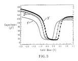
- FIG. 3depicts capacitance v.
- an nFET devicecomprising a 2.5 nm thick SiO 2 dielectric layer (control), as indicated by reference number 1 ′; an nFET device comprising a 3.0 nm HfSiO high k dielectric atop a 1.0 nm SiO 2 dielectric layer, as indicated by reference number 2 ′; and an nFET device comprising an AlN insulating interlayer atop a 3.0 nm HfSiO high k dielectric atop a 1.0 nm SiO 2 dielectric layer, as indicated by reference number 3 ′.
- the positive shift in the threshold voltage V t due to the incorporation of the AlN insulating interlayer within the nFET deviceis an equally unfavorable characteristic as the original negative shift in the threshold voltage V t of the pFET device, without the AlN insulating interlayer.
- Prior methods to remove the AlN insulating layer from the nFET device region, without destroying the underlying nFET device region surface or removing the AlN insulating layer from the pFET device region,are not known.
- Prior etchantssuch as KOH or dry reactive etching techniques are undesirable due to their deleterious impact on the underlying high k dielectric.
- an insulating interlayere.g. AlN
- the present inventionadvantageously stabilizes the threshold voltage V t and flatband voltage V fb in pFET devices by providing an insulating interlayer between the high k dielectric and the gate conductor, wherein the insulating interlayer prevents interaction between the high k gate dielectric and the gate conductor by spatial separation.
- the threshold V t and flatband voltage V fb shift attributed to the incorporation of the insulating interlayer in the nFET devicesis stabilized by removing the insulating interlayer from the nFET devices, without etching the nFET devices or removing the insulating interlayer from the pFET device region.
- the inventive method for providing a CMOS structure having high k dielectric pFET and nFET devicescomprises the steps of:
- dielectric stackatop said semiconducting substrate including said first device region and said second device region, said dielectric stack comprising an insulating interlayer atop a high k dielectric;
- the first device regionis the area in which nFET devices are formed, while the second device region is the area in which pFET devices are formed.
- the insulating interlayer employed in the present inventionis any insulating material that is capable of preventing interaction between the high k gate dielectric and the gate conductor by spatial separation. Moreover, the insulating interlayer employed in the present invention has a sufficiently high dielectric constant (on the order of about 4.0 or greater) such that there is a minimal decrease in gate capacitance (due to series capacitance effect) with its addition.
- the insulating interlayer of the present inventionis substantially non-reactive with the underlying high k gate dielectric; therefore it does not react with the high k gate dielectric forming a silicide.
- the insulating interlayer of the present inventionis also non-reactive with the above lying gate conductor.
- inventive insulating interlayeris that it is chemically stable so that silicon cannot reduce it.
- inventive insulating interlayershould not be an n-type dopant to silicon. Rather, the inventive insulating interlayer can be either a p-type dopant or a neutral dopant so that device performance is not adversely affected.
- the insulating interlayer employed in the present inventionshould be a refractory compound that is able to withstand high temperatures (of approximately 1000° C., typical of standard CMOS processing).
- Insulating materials that fit the above mentioned criteria and are thus employed as the insulating interlayer of the present inventioninclude any insulating metal nitride, i.e., metal nitride containing material, that may optional include oxygen therein.
- insulating interlayersinclude, but are not limited to: aluminum nitride (AlN), aluminum oxynitride (AlO x N y ), boron nitride (BN), boron oxynitride (BO x N y ), gallium nitride (GaN), gallium oxynitride (GaON), indium nitride (InN), indium oxynitride (InON) and combinations thereof.
- AlNaluminum nitride
- AlO x N yaluminum oxynitride
- BNboron nitride
- BO x N yboron nitride
- GaNgallium nitride
- the insulating interlayeris a thin interlayer located between the high k gate dielectric and the gate conductor. Typically, the insulating interlayer has a thickness in the range from about 1 to about 25 ⁇ , with a thickness from about 2 to about 15 ⁇ being more typical.
- the insulating interlayeris formed by deposition or thermal growing. The deposition comprises plating, sputtering, atomic layer chemical vapor deposition (ALCVD) or metal organic chemical vapor deposition (MOCVD).
- the high k dielectriccomprises any dielectric material having a dielectric constant greater than 4.0, preferably being greater than 7.0.
- the high k dielectriccomprises HfO 2 , hafnium silicate or hafnium silicon oxynitride.
- the high k dielectricis formed by deposition or thermal growing. Thermal growing may comprise oxidation, nitridation, and/or oxynitridation. Deposition may comprise chemical vapor deposition (CVD), plasma-enhanced CVD (PECVD), metal organic chemical vapor deposition (MOCVD), high-density chemical vapor deposition (HDCVD), plating, sputtering, evaporation and/or chemical solution deposition.
- CVDchemical vapor deposition
- PECVDplasma-enhanced CVD
- MOCVDmetal organic chemical vapor deposition
- HDCVDhigh-density chemical vapor deposition
- Removing the insulating interlayer from the first device region, without removing the insulating interlayer from the second device regioncan include forming a block mask atop the second device region, wherein the first device region is exposed; and etching the insulating interlayer from the first device region.
- the insulating interlayermay be etched by an etch chemistry that removes the insulating interlayer without substantially etching the block mask positioned in the second device region and the portion of the high k dielectric positioned underlying the insulating interlayer in the first device region.
- CMOS structureprovided by the above method.
- the present inventionprovides a CMOS structure comprising:
- a semiconductor substratehaving a first device region and a second device region
- said first device regioncomprising at least one first gate stack comprising a first high k gate dielectric and a first gate conductor
- said second device regioncomprising at least one second gate stack comprising a second high k dielectric, an insulating interlayer atop said high k gate, and a second gate conductor atop said insulating layer, wherein said insulating interlayer is capable of stabilizing said second device regions threshold voltage and flatband voltage without shifting said first device regions threshold voltage and flatband voltage.
- the quantities E c and E vdenote the conduction and the valence band edge, respectively, in the silicon substrate and in the polysilicon gate.
- E fdenotes the Fermi level position (dotted line) in the silicon substrate and in the polysilicon gate at zero gate bias.
- FIG. 2is a graph showing the capacitance-voltage curves for three types of pFET devices.
- the capacitance voltage curvesinclude a plot for a pFET comprising a AlN threshold insulating interlayer on a 3 nm HfSiO high k dielectric on a 1 nm SiO 2 dielectric layer; a pFET comprising a 3 nm HfSiO high k dielectric on a 1 nm SiO 2 dielectric layer; and a pFET comprising a 2.5 nm thick SiO 2 dielectric layer.
- FIG. 3is a graph showing the capacitance-voltage curves for three types of nFET devices.
- the capacitance voltage curvesinclude a plot for an nFET comprising a AlN threshold insulating interlayer on a 3 nm HfSiO high k dielectric on a 1 nm SiO 2 dielectric layer; an nFET comprising a 3 nm HfSiO high k dielectric on a 1 nm SiO 2 dielectric layer; and an nFET comprising a 2.5 nm thick SiO 2 dielectric layer.
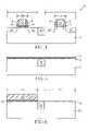
- FIG. 4is a pictorial representation (through a cross sectional view) of the inventive CMOS structure that includes a pFET device region having a threshold voltage V t stabilizing insulating interlayer between a high k gate dielectric and a poly-Si gate conductor and an nFET device region from which the insulating interlayer has been removed using the selective etch process of the present invention.
- FIGS. 5–8are pictorial representations (through a cross sectional views) of the process steps for the inventive method, which provides the CMOS structure depicted in FIG. 4 .
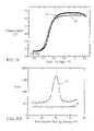
- FIG. 9is a plot showing capacitance voltage characteristics of the inventive CMOS structure, in which the insulating interlayer has been removed from the nFET device.
- FIG. 10is an XPS spectra depicting AlN content following the inventive selective etch process.
- the present inventionwhich provides a CMOS structure having an insulating interlayer (e.g., AlN interlayer) between a high k gate dielectric and a gate conductor of at least one pFET device, without incorporating the insulating interlayer into the nFET devices, wherein the positioning of the insulating interlayer stabilizes the threshold voltage V t and flatband voltage V fb for both pFET and nFET devices, and a method of fabricating the same will now be described in greater detail.
- insulating interlayerdenotes a metal-nitride containing interlayer which can include metal nitride and metal oxynitride materials.
- FIG. 4is a pictorial representation (through a cross sectional view) showing the CMOS structure 10 of the present invention.
- the CMOS structure 10includes a semiconductor substrate 12 having a pFET device region 15 and an nFET device region 25 separated by an isolation region 30 .
- the drawingsshow the presence of only two field effect transistors (FETs) on one substrate 12 , multiple FETs are also within the scope of the present invention.
- the pFET device region 15comprises at least one pFET having p-type source/drain regions 13 .
- Each of the pFETscomprises a gate region 18 having a gate conductor 24 atop an insulating interlayer 22 atop a high k dielectric 20 .
- At least one set of sidewall spacers 6are positioned abutting the gate conductor 24 .
- the nFET device region 25comprises at least one nFET having n-type source/drain regions 14 .
- Each of the nFETsfurther comprises a gate region 18 , including a gate conductor 24 atop a high k dielectric 20 , in which the gate conductor 24 is abutted by at least one set of sidewall spacers 6 .
- the insulating interlayer 22is positioned to stabilize the threshold voltage V t and flatband voltage V fb in pFET devices, without shifting the threshold voltage V t and flatband voltage V fb of the nFET devices, thereby providing a solution to the fabrication of CMOS transistors with the appropriate threshold and flatband voltages.
- the insulating interlayer 22 employed in the present inventionhas at least one of the following characteristics: (i) it is capable of preventing interaction between the high k gate dielectric 20 and the gate conductor 24 by spatial separation; (ii) it has a sufficiently high dielectric constant (on the order of about 4.0 or greater) such that there is a minimal decrease in gate capacitance (due to series capacitance effect) because of its addition; (iii) it may dissociate, at least partially, to provide a supply of p-type dopants in the near interfacial layer to ensure p-type behavior of near interfacial Si-containing material of the gate conductor 24 in the pFET device region 15 ; (iv) it can prevent outdiffusion of atoms from the high k gate dielectric 20 to the gate conductor 24 ; and (v) it can prevent oxidation under the gate conductor 24 .
- Examples of insulating interlayers 22include aluminum nitride (AlN), aluminum oxynitride (AlO x N y ), boron nitride (BN), boron oxynitride (BO x N y ), gallium nitride (GaN), gallium oxynitride (GaON), indium nitride (InN), indium oxynitride (InON) and combinations thereof.
- the insulating interlayer 22is AlN.
- blanket layers of high k dielectric 20 and insulating interlayer 22are formed on a surface of a semiconductor substrate 12 .
- the high k dielectric 20is located between the insulating interlayer 22 and the semiconductor substrate 12 .
- the semiconductor substrate 12 employed in the present inventioncomprises any semiconducting material including, but not limited to: Si, Ge, SiGe, SiC, SiGeC, Ga, GaAs, InAs, InP and all other III/V or II/VI compound semiconductors.
- Semiconductor substrate 12may also comprise an organic semiconductor or a layered semiconductor such as Si/SiGe, a silicon-on-insulator (SOI) or a SiGe-on-insulator (SGOI).
- SOIsilicon-on-insulator
- SGOISiGe-on-insulator
- the semiconductor substrate 12may be doped, undoped or contain doped and undoped regions therein.
- the semiconductor substrate 12may also include a first doped (n- or p-) region, and a second doped (n- or p-) region.
- n- or p-first doped
- n- or p-second doped
- the first doped region and the second doped regionmay be the same, or they may have different conductivities and/or doping concentrations. These doped regions are known as “wells”.
- the isolation region 30is then typically formed into the semiconductor substrate 12 .
- the isolation region 30may be a trench isolation region or a field oxide isolation region.
- the trench isolation regionis formed utilizing a conventional trench isolation process well known to those skilled in the art. For example, lithography, etching and filling of the trench with a trench dielectric may be used in forming the trench isolation region.
- a linermay be formed in the trench prior to trench fill, a densification step may be performed after the trench fill and a planarization process may follow the trench fill as well.
- the field oxidemay be formed utilizing a so-called local oxidation of silicon process.
- the at least one isolation regionprovides isolation between neighboring gate regions, typically required when the neighboring gates have opposite conductivities.
- the neighboring gate regionscan have the same conductivity (i.e., both n- or p-type), or alternatively they can have different conductivities (i.e., one n-type and the other p-type).
- a high k gate dielectric 20is formed on a surface of the structure.
- the high k gate dielectric 20can be formed by a thermal growth process such as, for example, oxidation, nitridation or oxynitridation.
- the high k gate dielectric 20can be formed by a deposition process such as, for example, chemical vapor deposition (CVD), plasma-assisted CVD, metalorganic chemical vapor deposition (MOCVD), atomic layer deposition (ALD), evaporation, reactive sputtering, chemical solution deposition and other like deposition processes.
- the high k gate dielectric 20may also be formed utilizing any combination of the above processes.
- the high k gate dielectric 20is comprised of an insulating material having a dielectric constant of greater than about 4.0, preferably greater than 7.0.
- the high k gate dielectric 20 employed in the present inventionincludes, but is not limited to: oxide, nitride, oxynitride and/or silicate including metal silicates and nitrided metal silicates.
- it is preferred that the gate dielectric 20is comprised of an oxide such as, for example, HfO 2 , ZrO 2 , Al 2 O 3 , TiO 2 , La 2 O 3 , SrTiO 3 , LaAlO 3 , Y 2 O 3 and mixtures thereof.
- Highly preferred examples of high k dielectrics 20include HfO 2 , hafnium silicate and hafnium silicon oxynitride.
- the physical thickness of the high k gate dielectric 20may vary, but typically, the high k gate dielectric 20 has a thickness from about 0.5 to about 10 nm, with a thickness from about 0.5 to about 3 nm being more typical. It may be deposited above a thin (on the order of about 0.1 to about 1.5 nm) layer of silicon oxide or silicon oxynitride that is first deposited on the substrate.
- the high k dielectricmay be selectively deposited on portions of the substrate using block masks as known within the skill of the art.
- a first portion of the substratemay be processed to provide a first high k dielectric for a first device type, such as an nFET, and a second portion of the substrate may be processed to provide a second high k dielectric for a second device type, such as a pFET.
- insulating interlayer 22is formed atop the blanket layer of high k gate dielectric 20 .
- the insulating interlayer 22 of the present inventionis a chemical interlayer that prevents interaction between the high k gate dielectric 20 and the subsequently formed gate conductor 24 .
- the insulating interlayer 22 of the present inventionis substantially non-reactive (there may be slight or partial decomposition, such as when its acts as a dopant source) with the underlying high k dielectric 20 ; therefore it does not react with the high k dielectric 20 to form a silicide.
- Another characteristic feature of the inventive insulating interlayer 22is that silicon cannot reduce the inventive insulating interlayer 22 .
- the inventive interlayer 22should be either a p-type dopant or a neutral dopant so that device performance is not adversely affected.
- the p-type dopantsdoes not dissociate into the portion of the device in which nFET devices are subsequently formed.
- the insulating interlayer 22 employed in the present inventionshould be a refractory compound that is able to withstand high temperatures (of approximately 1000° C., typical of standard CMOS processing).
- Insulating materials that fit the above-mentioned criteria and are thus employed as the insulating interlayer 22 of the present inventioninclude any insulating metal nitride that may optional include oxygen therein.
- insulating interlayersinclude, but are not limited to: aluminum nitride (AlN), aluminum oxynitride (AlO x N y ), boron nitride (BN), boron oxynitride (BO x N y ), gallium nitride (GaN), gallium oxynitride (GaON), indium nitride (InN), indium oxynitride (InON) and combinations thereof
- the insulating interlayer 22is AlN or AlO x N y .
- the insulating interlayer 22is a thin layer that typically has a thickness from about 1 to about 25 ⁇ , with a thickness from about 2 to about 15 ⁇ being more typical.
- the insulating interlayer 22can be formed by various deposition processes such as, for example, chemical vapor deposition (CVD), plasma-assisted CVD, atomic layer deposition (ALD) using aluminum and nitrogen-based precursors, physical vapor deposition or molecular beam deposition where the metal is evaporated along with a beam or ambient of atomic or molecular nitrogen (that may be optionally an excited species) and optionally oxygen, metalorganic chemical vapor deposition (MOCVD), atomic layer deposition, sputtering, and the like.
- the insulating interlayer 22can be formed by thermal nitridation or oxynitridation of a previously deposited insulating metal layer.
- the oxynitride of the metalmay be created by first depositing the metal nitride, followed by partial oxidation in a suitable oxygen environment to create and oxynitride.
- One preferred method of forming the interlayer insulating layer 22is by evaporating, under a high vacuum, Al from a standard Al effusion cell that is resistively heated, and using a nitrogen, or oxygen and nitrogen beams from commercial radio frequency (RF) atomic nitrogen or nitrogen and oxygen sources.
- RFradio frequency
- a nitrogen, or oxygen and nitrogen beamsfrom commercial radio frequency (RF) atomic nitrogen or nitrogen and oxygen sources.
- RFradio frequency
- a nitrogen, or oxygen and nitrogen beamsfrom commercial radio frequency (RF) atomic nitrogen or nitrogen and oxygen sources.
- RFradio frequency
- the effusion celltypically has a temperature from about 1000° C.–1200° C. during the evaporation process.
- the evaporation processis typically performed using a RF source having a power from about 200–450 W and a flow rate from about 1–3 sccm. These numbers can also be widely varied from the stated bounds without problems.
- the substrate temperatureis typically kept between 150° C. to 650° C. during deposition. Again, the deposition temperature can also be varied outside the stated ranges.
- Base vacuum chamber pressureis typically about 5 ⁇ 10 ⁇ 10 to 2 ⁇ 10 ⁇ 9 torr.
- the insulating interlayer 22 formed in the present inventionis a continuous and uniform layer that is present atop the high k gate dielectric 20 .
- continuousit is meant that the insulating interlayer 22 contains no substantial breaks and/or voids therein; by “uniform” it is meant that the insulating interlayer 22 has nearly the same, as deposited, thickness across the structure.
- the insulating interlayer 22may be amorphous meaning that it can lack a specific crystal structure.
- the insulating interlayer 22may exist in other phases besides amorphous depending on the material used as well as the technique that is used in forming the same.
- a block mask 50is formed protecting the portion of the substrate 12 in which pFETs are subsequently formed. This portion of the substrate is hereafter referred to as the pFET device region 15 .
- the exposed portion of the substrate that is not protected by the block maskis subsequently processed to provide nFET devices and is hereafter referred to as the nFET device region 25 .
- the block mask 50may comprise conventional soft and/or hardmask materials and can be formed using deposition, photolithography and etching.
- the block mask 50comprises a photoresist.
- a photoresist block mask 50can be produced by applying a photoresist layer to the substrate 12 surface, exposing the photoresist layer to a pattern of radiation, and then developing the pattern into the photoresist layer utilizing conventional resist developer.
- the block mask 50can be a hardmask material.
- Hardmask materialsinclude dielectrics systems that may be deposited by chemical vapor deposition (CVD) and related methods.
- the hardmask compositionincludes silicon oxides, silicon carbides, silicon nitrides, silicon carbonitrides, etc.
- Spin-on dielectricsmay also be utilized as a hardmask material including but not limited to: silsequioxanes, siloxanes, and boron phosphate silicate glass (BPSG).
- BPSGboron phosphate silicate glass
- a block mask 50 comprising hardmask materialmay be formed by blanket depositing a layer of hardmask material; providing a patterned photoresist atop the layer of hardmask material; and then etching the layer of hardmask material to provide a block mask 50 protecting the pFET device region 15 , in which etching comprises an etch chemistry having a high selectivity to the patterned photoresist and the surface of the nFET device region 25 .
- the exposed portion of the insulating interlayer 22is removed from the nFET device region 25 using a highly selective etch process.
- This highly selective etchpreferably comprises an etch chemistry which removes the exposed portion of the insulating interlayer 22 from the nFET device region 25 , without substantially etching the underlying high k dielectric 20 or the block mask 50 that protects the pFET device region 15 .
- a wet etchremoves the insulating interlayer 22 from the nFET device region 25 , without etching the underlying high k dielectric 20 or the block mask 50 .
- this etch chemistryremoves the AlN insulating interlayer 22 , without substantially etching an underlying hafnium silicate high k dielectric 20 .
- Prior etch methodscannot selectively remove AlN without etching the underlying high k dielectric 20 .
- wet etchantssuch as KOH
- dry etch techniquessuch as RIE
- the wet etch chemistrycomprises a solution of HCl and peroxide, the preferred concentration being 3:1 HCl:H 2 O 2 .
- HCl/peroxide solutionsit is proposed that other inorganic acids and oxidizing agents can produce the same results so long as the etch chemistry does not attack the high k dielectric 20 .
- the oxidizing agentsmay include peroxides, nitrates, nitrites, perchlorates, chlorates, chlorites, hypochlorites, dichromates, permanganates, persulfates or combinations thereof.
- the inorganic acidscan include sulfuric acid, phosphoric acid or combinations thereof. Etch rate may be impacted by the pH of the etch chemistry.
- the pH of the etch chemistrymay range from about 1 to about 8, preferably ranging from about 2 to about 6, most preferably being about 2.8.
- the etch compositioncan be mixed during an exothermic reaction.
- the wet etchmay be conducted in an oxygen-containing environments and may be conducted at room temperature or at an elevated temperature. Preferably, the etch temperature is 15° C. to 80° C.
- the block mask 50is removed using a chemical strip and the substrate 12 is rinsed with deionized water and dried in a N 2 ambient.
- the gate conductor 24may comprise any conductive material known by those skilled in the art.
- the gate conductor materialcan comprise polysilicon but may also be comprised of SiGe, SiGeC, metal silicides, metallic nitrides, metals (for example W, Ir, Re, Ru, Ti, Ta, Hf, Mo, Nb, Ni, Al), or a combination of the above.
- the at least one gate conductormay be deposited using chemical vapor deposition (CVD), plasma-enhanced chemical vapor deposition (PECVD), high-density chemical vapor deposition (HDCVD), plating, sputtering, evaporation or chemical solution deposition.
- CVDchemical vapor deposition
- PECVDplasma-enhanced chemical vapor deposition
- HDCVDhigh-density chemical vapor deposition
- platingsputtering, evaporation or chemical solution deposition.
- the gate conductor 24 formed in the pFET device region 15 and the nFET device region 25may be the same or a different material.
- block masksmay be utilized to selectively process the gate conductor 24 materials in the pFET device region 15 and the nFET device region 25 .
- a blanket layer of a Si-containing materialis formed on the insulating interlayer 22 in the pFET device region 15 and on the high k dielectric 20 in the nFET device region 25 utilizing a known deposition process including, but not limited to: physical vapor deposition, CVD or evaporation.
- the Si-containing material used in forming the gate conductor 24includes Si or a SiGe alloy layer in single crystal, polycrystalline or amorphous form. Combinations of the aforementioned Si-containing materials are also contemplated herein.
- the blanket layer of Si-containing materialmay be doped or undoped. If doped, an in-situ doping deposition process may be employed in forming the same.
- a doped Si-containing layercan be formed by deposition, ion implantation and annealing.
- the doping of the Si-containing layerwill shift the workfunction of the gate conductor 24 formed.
- dopant ionsinclude As, P, B, Sb, Bi, In, Al, Ga, or mixtures thereof, preferably being P.
- the thickness, i.e., height, of the Si-containing layer deposited at this point of the present inventionmay vary depending on the deposition process employed.
- the Si-containing layerhas a vertical thickness from about 20 to about 180 nm, with a thickness from about 40 to about 150 nm being more typical.
- a dielectric cap layer(not shown) can be formed atop the blanket layer of gate conductor material utilizing a deposition process such as, for example, physical vapor deposition or chemical vapor deposition.
- the dielectric cap layermay be an oxide, nitride, oxynitride or any combination thereof.
- the thickness, i.e., height, of the dielectric cap layeris from about 20 to about 180 nm, with a thickness from about 30 to about 140 nm being more typical.
- the dielectric cap (if present), the blanket gate conductor layer, and optionally the insulating interlayer 22 and the high k gate dielectric 20 in the pFET device region 15 and the high k gate dielectric in the nFET device region 25are then patterned by lithography and etching so as to provide at least one patterned gate stack 18 in the nFET and pFET device regions 15 , 25 .
- the gate stacks 18may have the same dimension, i.e., length, or they can have variable dimensions to improve device performance.
- Each patterned gate stack 18 at this point of the present inventionincludes at least the gate conductor 24 .
- the lithography stepincludes applying a photoresist to the upper surface of the blanket layered structure, exposing the photoresist to a desired pattern of radiation and developing the exposed photoresist utilizing a conventional resist developer.
- the pattern in the photoresistis then transferred to the structure utilizing one or more dry etching steps.
- the patterned photoresistmay be removed after the pattern has been transferred into one of the layers of the blanket layered structure. In other embodiments, the patterned photoresist is removed after etching has been completed.
- Suitable dry etching processesthat can be used in the present invention in forming the patterned gate stacks include, but are not limited to: reactive ion etching, ion beam etching, plasma etching or laser ablation.
- the dry etching process employedis typically, but not always, selective to the underlying high k dielectric 20 in the nFET device region 25 and the insulating interlayer 22 in the pFET device region 15 . Therefore this etching step does not typically remove the exposed portions of the insulating interlayer 22 and the high k dielectric 20 . In some embodiments, this etching step may however be used to remove portions of the high k dielectric 20 and the insulating interlayer 22 that are not protected by the gate conductor 24 that were previously etched.
- At least one set of spacers 6is typically, but not always, formed on exposed sidewalls of each patterned gate stack 18 .
- the at least one set of spacers 6is comprised of an insulator such as an oxide, nitride, oxynitride and/or any combination thereof.
- the at least one set of spacers 6is formed by deposition and etching.
- the width of the at least one spacer 6must be sufficiently wide such that the source and drain silicide contacts (to be subsequently formed) do not encroach underneath the edges of the gate stack.
- the source/drain silicidedoes not encroach underneath the edges of the gate stack when the at least one spacer has a width, as measured at the bottom, from about 20 to about 80 nm.
- the gate stack 18can also be passivated at this point of the present invention by subjecting the same to a thermal oxidation, nitridation or oxynitridation process.
- the passivation stepforms a thin layer of passivating material about the gate stack. This step may be used instead or in conjunction with the previous step of spacer formation. When used with the spacer formation step, spacer formation occurs after the gate stack passivation process.
- Source/drain diffusion regions 13 , 14are then formed into the substrate.
- the source/drain diffusion regions 13 , 14are formed utilizing ion implantation and an annealing step.
- P-type source/drain diffusion regions 13are formed within the pFET device region 15 and n-type source/drain diffusion regions 14 are formed within the nFET device region 25 .
- the annealing stepserves to activate the dopants that were implanted by the previous implant step.
- the conditions for the ion implantation and annealingare well known to those skilled in the art.
- the source/drain diffusion regions 13 , 14may also include extension implant regions, which are formed prior to source/drain implantation using a conventional extension implant having the same dopant type as the corresponding source/drain diffusion regions.
- the extension implantmay be followed by an activation anneal, or alternatively the dopants implanted during the extension implant and the source/drain implant can be activated using the same activation anneal cycle. Halo implants are also contemplated herein.
- the exposed portion of the high k dielectric 20is removed from the nFET device region 25 and the exposed portions of the insulating interlayer 22 and the high k dielectric 20 are removed from the pFET device region 25 utilizing a highly selective chemical etching process.
- This etching stepstops on an upper surface of the semiconductor substrate 12 .
- any chemical etchantmay be used in removing the exposed portions of the high k dielectric 20 and the insulating interlayer 22 , in one embodiment dilute hydrofluoric acid (DHF) is used.
- DHFdilute hydrofluoric acid
- CMOS structure of the present inventionis one in which the high k gate dielectric 20 is comprised of HfO 2 , hafnium silicate or hafnium silicon oxynitride and the insulating interlayer 22 is comprised of AlN, which optionally may include some oxygen therein.
- the particularly preferred structureare also contemplated herein and should not be excluded.
- CMOS processingsuch as formation of silicided contacts (source/drain and gate) as well as formation of BEOL (back-end-of-the-line) interconnect levels with metal interconnects can be formed utilizing processing steps that are well known to those skilled in the art.
- CMOS structurein which the inventive insulating interlayer 22 positioned only within pFET devices and removed from nFET devices.
- a Hf oxide or silicate layer(high k dielectric) was grown on a silicon substrate that was pre-patterned with an isolation region separating an nFET device region from a pFET device region.
- the Hf oxide and silicatewere deposited using metal organic chemical vapor deposition (MOCVD) and atomic layer chemical vapor deposition (ALCVD).
- MOCVDmetal organic chemical vapor deposition
- ACVDatomic layer chemical vapor deposition
- the thicknesses of the Hf oxide and silicate layerswere in the range of about 2 nm to about 4 nm and for the silicates, the composition was approximately Hf x Si y O 4 with y/(x+y) being approximately 0.2–0.3.
- These oxideswere deposited on an n-type silicon wafer having 0.3 nm to 1.2 nm thick silicon oxide or silicon oxynitride coating. The presence of this silicon oxide or silicon oxynitride coating is optional.
- the waferswere loaded in an ultra-high vacuum deposition chamber for aluminum nitride deposition (insulating interlayer).
- Aluminum nitridewas deposited by evaporating Al from a standard Al effusion cell that is resistively heated, and using a nitrogen beam from a commercial radio frequency atomic nitrogen source.
- the effusion cellhad a temperature of 1000° C.–1200° C. during operation.
- the atomic nitrogen sourcewas operated in the range of 200–450 W and a nitrogen flow rate of 1–3 sccm.
- the substrate temperaturewas kept between 150° C. to 650° C. during deposition.
- Base vacuum chamber pressurewas about 5 ⁇ 10 ⁇ 10 to 2 ⁇ 10 ⁇ 9 torr. During AlN deposition the pressure rose to the 1 ⁇ 10 ⁇ 5 torr range.
- the AlN layerswere deposited to a thicknesses ranging from about 0.5 nm to about 2.0 nm.
- the substrateswere then taken out and etched in a HCl:H 2 O 2 peroxide solution to remove the AlN layers, with no external heat supplied.
- the concentrations of this etchant solutioncomprised greater than 1 part HCl and greater than 1.5 parts H 2 O 2 , wherein an acidic solution was provided.
- the preferred concentrationcomprises 3:1 HCl:H 2 O 2 . It is noted that the pH resulting from the choice of concentration as described-above will impact the etch rate.
- the substrateswere rinsed with de-ionized water and dried in a N 2 ambient to provide a substrate having a Hf oxide surface.
- amorphous silicon layer(gate conductor layer) was then deposited atop the substrate surface to a thickness of approximately 150 nm thick using chemical vapor deposition using standard procedures.
- the amorphous silicon layerwas then ion implanted with phosphorus and the dopants activated by annealing at approximately 950° C. to approximately 1000° C., again following standard semiconductor processing procedures. In some cases, forming gas anneals were performed for SiO 2 /Si(100) interface state passivation.
- NMOS test capacitorswere then formed from these above structures using chemical vapor deposition and etching to define pad shapes on the order of about 20 ⁇ 20 square microns.
- the NMOS test capacitor structureswere etched using the above-described method to remove the AlN layer to provide a structure comprising a phosphorus doped polysilicon layer; a layer of Hf silicate or HfO 2 having a thickness ranging from about 2 nm to about 4 nm; and an SiO 2 or SiON layer having a thickness ranging from about 0.3 nm to about 1.2 nm; and a silicon (100) substrate.
- Capacitance-voltage curves for nMOS test capacitors with Hf silicate or HfO 2 as the gate dielectric and having an AlN layer deposited thereon and then removed by the selective etch of the present inventionare indicated by reference number 55 .
- Capacitance-voltage curves for the control capacitorsare indicated by reference number 60 .
- the flatband voltage V fb in the capacitance voltage curves for the capacitorsis equivalent to threshold voltage V t in transistors.
- comparison of the flatband voltage V fb of the test capacitors to the control capacitorsindicates that the flatband voltage V fb of the test capacitors was within 70 mV of the control capacitors. Therefore, since AlN can be removed from the surface of the test capacitors without substantially degrading the device's flatband voltage V fb ; the etch chemistries of the present invention can advantageously remove AlN without etching the underlying Hf silicate or HfO 2 high k dielectric or disadvantageously effecting the electrical properties of the Hf silicate or HfO 2 high k dielectric.
- an XPS spectrais provided of a blanket AlN film etched from a hafnium silicate surface by an etch chemistry comprising a HCl:H 2 O 2 solution in 3:1 ratio for 15 minutes.
- the XPS spectra of the HCl/peroxide etched surfaceis indicated by reference number 75 and the XPS surface of an AlN control surface is indicated by reference number 80 .
- the Al 2P peak detected from the AlN control surfaceis not present in the AlN film which was etched from the hafnium surface by the HCl/peroxide solution.
- the selectivity to hafnium silicatewas confirmed using the ellipsometry measurements, which showed no change in the thickness of the hafnium silicate film.
Landscapes
- Engineering & Computer Science (AREA)
- Manufacturing & Machinery (AREA)
- Physics & Mathematics (AREA)
- Condensed Matter Physics & Semiconductors (AREA)
- General Physics & Mathematics (AREA)
- Computer Hardware Design (AREA)
- Microelectronics & Electronic Packaging (AREA)
- Power Engineering (AREA)
- Composite Materials (AREA)
- Chemical & Material Sciences (AREA)
- Metal-Oxide And Bipolar Metal-Oxide Semiconductor Integrated Circuits (AREA)
- Insulated Gate Type Field-Effect Transistor (AREA)
- Weting (AREA)
- Thin Film Transistor (AREA)
Abstract
Description
Claims (26)
Priority Applications (12)
| Application Number | Priority Date | Filing Date | Title |
|---|---|---|---|
| US10/863,830US7105889B2 (en) | 2004-06-04 | 2004-06-04 | Selective implementation of barrier layers to achieve threshold voltage control in CMOS device fabrication with high k dielectrics |
| US10/957,342US7479683B2 (en) | 2004-06-04 | 2004-10-01 | Selective implementation of barrier layers to achieve threshold voltage control in CMOS device fabrication with high-k dielectrics |
| KR1020067025229AKR100951227B1 (en) | 2004-06-04 | 2005-03-30 | Selective Implementation of Barrier Layers for Controlling Threshold Voltages in CMOS Devices with High-K dielectrics |
| JP2007515066AJP4711444B2 (en) | 2004-06-04 | 2005-03-30 | Method for forming complementary metal oxide semiconductor (CMOS) structures with improved threshold voltage and flat band voltage stability (barrier layer to achieve threshold voltage control in CMOS device formation with high-k dielectrics) Selective implementation) |
| CN2005800161892ACN101427386B (en) | 2004-06-04 | 2005-03-30 | Selective implementation of barrier layers for threshold voltage control in CMOS device fabrication with high-k dielectrics |
| EP05732384.2AEP1766691B1 (en) | 2004-06-04 | 2005-03-30 | Selective implementation of barrier layers to achieve threshold voltage control in cmos device fabrication with high k dielectrics |
| PCT/US2005/010825WO2005122286A2 (en) | 2004-06-04 | 2005-03-30 | Selective implementation of barrier layers to achieve threshold voltage control in cmos device fabrication with high k dielectrics |
| TW094118832ATWI380378B (en) | 2004-06-04 | 2005-06-06 | Selective implementation of barrier layers to achieve threshold voltage control in cmos device fabrication with high-k dielectrics |
| US11/500,254US7452767B2 (en) | 2004-06-04 | 2006-08-07 | Selective implementation of barrier layers to achieve threshold voltage control in CMOS device fabrication with high k dielectrics |
| US12/211,530US7745278B2 (en) | 2004-06-04 | 2008-09-16 | Selective implementation of barrier layers to achieve threshold voltage control in CMOS device fabrication with high K dielectrics |
| US12/355,368US7928514B2 (en) | 2004-06-04 | 2009-01-16 | Selective implementation of barrier layers to achieve threshold voltage control in CMOS device fabrication with high-k dielectrics |
| US13/047,172US8193051B2 (en) | 2004-06-04 | 2011-03-14 | Selective implementation of barrier layers to achieve threshold voltage control in CMOS device fabrication with high-k dielectrics |
Applications Claiming Priority (1)
| Application Number | Priority Date | Filing Date | Title |
|---|---|---|---|
| US10/863,830US7105889B2 (en) | 2004-06-04 | 2004-06-04 | Selective implementation of barrier layers to achieve threshold voltage control in CMOS device fabrication with high k dielectrics |
Related Child Applications (2)
| Application Number | Title | Priority Date | Filing Date |
|---|---|---|---|
| US10/957,342Continuation-In-PartUS7479683B2 (en) | 2004-06-04 | 2004-10-01 | Selective implementation of barrier layers to achieve threshold voltage control in CMOS device fabrication with high-k dielectrics |
| US11/500,254DivisionUS7452767B2 (en) | 2004-06-04 | 2006-08-07 | Selective implementation of barrier layers to achieve threshold voltage control in CMOS device fabrication with high k dielectrics |
Publications (2)
| Publication Number | Publication Date |
|---|---|
| US20050269634A1 US20050269634A1 (en) | 2005-12-08 |
| US7105889B2true US7105889B2 (en) | 2006-09-12 |
Family
ID=35446743
Family Applications (6)
| Application Number | Title | Priority Date | Filing Date |
|---|---|---|---|
| US10/863,830Expired - LifetimeUS7105889B2 (en) | 2004-06-04 | 2004-06-04 | Selective implementation of barrier layers to achieve threshold voltage control in CMOS device fabrication with high k dielectrics |
| US10/957,342Expired - Fee RelatedUS7479683B2 (en) | 2004-06-04 | 2004-10-01 | Selective implementation of barrier layers to achieve threshold voltage control in CMOS device fabrication with high-k dielectrics |
| US11/500,254Expired - LifetimeUS7452767B2 (en) | 2004-06-04 | 2006-08-07 | Selective implementation of barrier layers to achieve threshold voltage control in CMOS device fabrication with high k dielectrics |
| US12/211,530Expired - LifetimeUS7745278B2 (en) | 2004-06-04 | 2008-09-16 | Selective implementation of barrier layers to achieve threshold voltage control in CMOS device fabrication with high K dielectrics |
| US12/355,368Expired - LifetimeUS7928514B2 (en) | 2004-06-04 | 2009-01-16 | Selective implementation of barrier layers to achieve threshold voltage control in CMOS device fabrication with high-k dielectrics |
| US13/047,172Expired - LifetimeUS8193051B2 (en) | 2004-06-04 | 2011-03-14 | Selective implementation of barrier layers to achieve threshold voltage control in CMOS device fabrication with high-k dielectrics |
Family Applications After (5)
| Application Number | Title | Priority Date | Filing Date |
|---|---|---|---|
| US10/957,342Expired - Fee RelatedUS7479683B2 (en) | 2004-06-04 | 2004-10-01 | Selective implementation of barrier layers to achieve threshold voltage control in CMOS device fabrication with high-k dielectrics |
| US11/500,254Expired - LifetimeUS7452767B2 (en) | 2004-06-04 | 2006-08-07 | Selective implementation of barrier layers to achieve threshold voltage control in CMOS device fabrication with high k dielectrics |
| US12/211,530Expired - LifetimeUS7745278B2 (en) | 2004-06-04 | 2008-09-16 | Selective implementation of barrier layers to achieve threshold voltage control in CMOS device fabrication with high K dielectrics |
| US12/355,368Expired - LifetimeUS7928514B2 (en) | 2004-06-04 | 2009-01-16 | Selective implementation of barrier layers to achieve threshold voltage control in CMOS device fabrication with high-k dielectrics |
| US13/047,172Expired - LifetimeUS8193051B2 (en) | 2004-06-04 | 2011-03-14 | Selective implementation of barrier layers to achieve threshold voltage control in CMOS device fabrication with high-k dielectrics |
Country Status (7)
| Country | Link |
|---|---|
| US (6) | US7105889B2 (en) |
| EP (1) | EP1766691B1 (en) |
| JP (1) | JP4711444B2 (en) |
| KR (1) | KR100951227B1 (en) |
| CN (1) | CN101427386B (en) |
| TW (1) | TWI380378B (en) |
| WO (1) | WO2005122286A2 (en) |
Cited By (39)
| Publication number | Priority date | Publication date | Assignee | Title |
|---|---|---|---|---|
| US20060030096A1 (en)* | 2004-08-06 | 2006-02-09 | Weimer Ronald A | Methods of enabling polysilicon gate electrodes for high-k gate dieletrics |
| US20060060929A1 (en)* | 2004-08-30 | 2006-03-23 | Gyoung-Ho Buh | Semiconductor transistors having surface insulation layers and methods of fabricating such transistors |
| US20060102968A1 (en)* | 2004-11-15 | 2006-05-18 | International Business Machines Corporation | Nitrogen-containing field effect transistor gate stack containing a threshold voltage control layer formed via deposition of a metal oxide |
| US20060228904A1 (en)* | 2005-04-07 | 2006-10-12 | Texas Instruments Incorporated | Protection of silicon from phosphoric acid using thick chemical oxide |
| WO2007050312A2 (en) | 2005-10-26 | 2007-05-03 | International Business Machines Corporation | Low threshold voltage semiconductor device with dual threshold voltage control means |
| US20070187774A1 (en)* | 2005-07-14 | 2007-08-16 | Matthias Goldbach | Manufacturing method for an integrated semiconductor structure and corresponding integrated semiconductor structure |
| US20070210354A1 (en)* | 2006-03-10 | 2007-09-13 | Renesas Technology Corp. | Semiconductor device and semiconductor device manufacturing method |
| US20070298560A1 (en)* | 2005-02-14 | 2007-12-27 | Kabushiki Kaisha Toshiba | Semiconductor Device |
| US20080038924A1 (en)* | 2006-08-08 | 2008-02-14 | Willy Rachmady | Highly-selective metal etchants |
| US20080264898A1 (en)* | 2007-04-27 | 2008-10-30 | International Business Machines Corporation | SELECTIVE ETCH OF TiW FOR CAPTURE PAD FORMATION |
| US20080274598A1 (en)* | 2007-03-19 | 2008-11-06 | Texas Instruments Inc. | Doped WGe to form dual metal gates |
| US20080318404A1 (en)* | 2004-09-13 | 2008-12-25 | Kabushiki Kaisha Toshiba | Semiconductor device and method for manufacturing the same |
| US20090108366A1 (en)* | 2007-10-30 | 2009-04-30 | Tze-Chiang Chen | Structure And Method To Fabricate Metal Gate High-K Devices |
| US20090152636A1 (en)* | 2007-12-12 | 2009-06-18 | International Business Machines Corporation | High-k/metal gate stack using capping layer methods, ic and related transistors |
| US20090174010A1 (en)* | 2008-01-03 | 2009-07-09 | International Business Machines Corporation | Sram device structure including same band gap transistors having gate stacks with high-k dielectrics and same work function |
| US7569500B2 (en) | 2002-06-14 | 2009-08-04 | Applied Materials, Inc. | ALD metal oxide deposition process using direct oxidation |
| US20090212369A1 (en)* | 2008-02-26 | 2009-08-27 | International Business Machines Corporation | Gate Effective-Workfunction Modification for CMOS |
| US20090263961A1 (en)* | 2008-04-22 | 2009-10-22 | Shreyas Kher | Hardware set for growth of high k & capping material films |
| US7645710B2 (en) | 2006-03-09 | 2010-01-12 | Applied Materials, Inc. | Method and apparatus for fabricating a high dielectric constant transistor gate using a low energy plasma system |
| US7678710B2 (en) | 2006-03-09 | 2010-03-16 | Applied Materials, Inc. | Method and apparatus for fabricating a high dielectric constant transistor gate using a low energy plasma system |
| CN101409234B (en)* | 2007-07-03 | 2010-10-20 | 国际商业机器公司 | A kind of semiconductor structure and its manufacturing method |
| US7837838B2 (en) | 2006-03-09 | 2010-11-23 | Applied Materials, Inc. | Method of fabricating a high dielectric constant transistor gate using a low energy plasma apparatus |
| US20100308412A1 (en)* | 2009-06-03 | 2010-12-09 | International Business Machines Corporation | Control of flatband voltages and threshold voltages in high-k metal gate stacks and structures for cmos devices |
| US20110031554A1 (en)* | 2009-08-04 | 2011-02-10 | International Business Machines Corporation | Structure and method to improve threshold voltage of mosfets including a high k dielectric |
| US7902018B2 (en) | 2006-09-26 | 2011-03-08 | Applied Materials, Inc. | Fluorine plasma treatment of high-k gate stack for defect passivation |
| US20110115026A1 (en)* | 2009-11-16 | 2011-05-19 | International Business Machines Corporation | Control of threshold voltages in high-k metal gate stack and structures for cmos devices |
| US20110223728A1 (en)* | 2004-12-20 | 2011-09-15 | Hong-Jyh Li | Transistor Device and Method of Manufacture Thereof |
| US8119210B2 (en) | 2004-05-21 | 2012-02-21 | Applied Materials, Inc. | Formation of a silicon oxynitride layer on a high-k dielectric material |
| US8350341B2 (en) | 2010-04-09 | 2013-01-08 | International Business Machines Corporation | Method and structure for work function engineering in transistors including a high dielectric constant gate insulator and metal gate (HKMG) |
| US8420474B1 (en) | 2012-01-11 | 2013-04-16 | International Business Machines Corporation | Controlling threshold voltage in carbon based field effect transistors |
| US8435878B2 (en) | 2010-04-06 | 2013-05-07 | International Business Machines Corporation | Field effect transistor device and fabrication |
| US20130140621A1 (en)* | 2011-12-01 | 2013-06-06 | National Chiao Tung University | Flash memory |
| US20130285154A1 (en)* | 2004-06-17 | 2013-10-31 | Infineon Technologies Ag | CMOS Transistor With Dual High-k Gate Dielectric |
| TWI502686B (en)* | 2008-02-28 | 2015-10-01 | Renesas Electronics Corp | Semiconductor device manufacturing method and semiconductor device |
| US9219160B2 (en) | 2011-09-29 | 2015-12-22 | Semiconductor Energy Laboratory Co., Ltd. | Semiconductor device |
| US9449887B2 (en) | 2014-12-08 | 2016-09-20 | Globalfoundries Inc. | Method of forming replacement gate PFET having TiALCO layer for improved NBTI performance |
| US9741860B2 (en) | 2011-09-29 | 2017-08-22 | Semiconductor Energy Laboratory Co., Ltd. | Semiconductor device |
| US11189616B2 (en) | 2019-09-17 | 2021-11-30 | International Business Machines Corporation | Multi-threshold voltage non-planar complementary metal-oxtde-semiconductor devices |
| US20230061138A1 (en)* | 2021-09-02 | 2023-03-02 | Mediatek Inc. | Semiconductor device structure and method of forming the same |
Families Citing this family (106)
| Publication number | Priority date | Publication date | Assignee | Title |
|---|---|---|---|---|
| JP4748927B2 (en)* | 2003-03-25 | 2011-08-17 | ローム株式会社 | Semiconductor device |
| TWI258811B (en)* | 2003-11-12 | 2006-07-21 | Samsung Electronics Co Ltd | Semiconductor devices having different gate dielectrics and methods for manufacturing the same |
| KR100618815B1 (en)* | 2003-11-12 | 2006-08-31 | 삼성전자주식회사 | Semiconductor device having heterogeneous gate insulating film and manufacturing method thereof |
| US7271455B2 (en)* | 2004-07-14 | 2007-09-18 | International Business Machines Corporation | Formation of fully silicided metal gate using dual self-aligned silicide process |
| JP2006086511A (en)* | 2004-08-17 | 2006-03-30 | Nec Electronics Corp | Semiconductor device |
| JP2006108439A (en)* | 2004-10-06 | 2006-04-20 | Samsung Electronics Co Ltd | Semiconductor device |
| US20060091483A1 (en)* | 2004-11-02 | 2006-05-04 | Doczy Mark L | Method for making a semiconductor device with a high-k gate dielectric layer and a silicide gate electrode |
| US20060094180A1 (en)* | 2004-11-02 | 2006-05-04 | Intel Corporation | Method for making a semiconductor device with a high-k gate dielectric layer and a silicide gate electrode |
| US7645687B2 (en)* | 2005-01-20 | 2010-01-12 | Chartered Semiconductor Manufacturing, Ltd. | Method to fabricate variable work function gates for FUSI devices |
| US7151023B1 (en)* | 2005-08-01 | 2006-12-19 | International Business Machines Corporation | Metal gate MOSFET by full semiconductor metal alloy conversion |
| KR100706784B1 (en)* | 2005-08-08 | 2007-04-12 | 삼성전자주식회사 | Semiconductor device and manufacturing method thereof. |
| US7622387B2 (en)* | 2005-08-29 | 2009-11-24 | Freescale Semiconductor, Inc. | Gate electrode silicidation process |
| US20080001183A1 (en)* | 2005-10-28 | 2008-01-03 | Ashok Kumar Kapoor | Silicon-on-insulator (SOI) junction field effect transistor and method of manufacture |
| JP2007157744A (en)* | 2005-11-30 | 2007-06-21 | Toshiba Corp | Semiconductor device and manufacturing method of semiconductor device |
| JP2007158065A (en)* | 2005-12-06 | 2007-06-21 | Nec Electronics Corp | Semiconductor device manufacturing method and semiconductor device |
| US7510943B2 (en)* | 2005-12-16 | 2009-03-31 | Infineon Technologies Ag | Semiconductor devices and methods of manufacture thereof |
| KR100744264B1 (en)* | 2005-12-28 | 2007-07-30 | 동부일렉트로닉스 주식회사 | Manufacturing Method of Semiconductor Device |
| US7833849B2 (en)* | 2005-12-30 | 2010-11-16 | International Business Machines Corporation | Method of fabricating a semiconductor structure including one device region having a metal gate electrode located atop a thinned polygate electrode |
| US7968947B2 (en)* | 2006-01-06 | 2011-06-28 | Nec Corporation | Semiconductor device and manufacturing process therefor |
| US20070161246A1 (en)* | 2006-01-10 | 2007-07-12 | Texas Instruments Incorporated | Process For Selectively Removing Dielectric Material in the Presence of Metal Silicide |
| US8912014B1 (en)* | 2006-01-18 | 2014-12-16 | Spansion Llc | Controlling the latchup effect |
| JP5177954B2 (en)* | 2006-01-30 | 2013-04-10 | キヤノン株式会社 | Field effect transistor |
| US20070221993A1 (en)* | 2006-03-27 | 2007-09-27 | Taiwan Semiconductor Manufacturing Company, Ltd. | Method for making a thermally stable silicide |
| EP1863097A1 (en)* | 2006-05-29 | 2007-12-05 | Interuniversitair Microelektronica Centrum ( Imec) | Method for modulating the effective work function |
| EP1863072A1 (en)* | 2006-05-29 | 2007-12-05 | Interuniversitair Microelektronica Centrum ( Imec) | Method for modulating the effective work function |
| JP4282691B2 (en)* | 2006-06-07 | 2009-06-24 | 株式会社東芝 | Semiconductor device |
| JP5034332B2 (en)* | 2006-06-14 | 2012-09-26 | 富士通セミコンダクター株式会社 | Manufacturing method of semiconductor device |
| US20080017936A1 (en)* | 2006-06-29 | 2008-01-24 | International Business Machines Corporation | Semiconductor device structures (gate stacks) with charge compositions |
| JP2008060538A (en)* | 2006-07-31 | 2008-03-13 | Toshiba Corp | Semiconductor device and manufacturing method thereof |
| JP5020591B2 (en)* | 2006-09-29 | 2012-09-05 | 鶴見曹達株式会社 | Etching solution for conductive polymer and method for patterning conductive polymer |
| CN103456626B (en)* | 2006-09-29 | 2016-06-08 | 东亚合成株式会社 | Etching liquid for conductive polymer and the method by electroconductive polymer patterning |
| EP1914800A1 (en)* | 2006-10-20 | 2008-04-23 | Interuniversitair Microelektronica Centrum | Method of manufacturing a semiconductor device with multiple dielectrics |
| KR20080046438A (en)* | 2006-11-22 | 2008-05-27 | 삼성전자주식회사 | Semiconductor device and manufacturing method thereof |
| JP2008131023A (en)* | 2006-11-27 | 2008-06-05 | Nec Electronics Corp | Semiconductor device and manufacturing method thereof |
| EP1944801A1 (en)* | 2007-01-10 | 2008-07-16 | Interuniversitair Microelektronica Centrum | Methods for manufacturing a CMOS device with dual work function |
| US20080206973A1 (en)* | 2007-02-26 | 2008-08-28 | Texas Instrument Inc. | Process method to optimize fully silicided gate (FUSI) thru PAI implant |
| US20080272435A1 (en)* | 2007-05-02 | 2008-11-06 | Chien-Ting Lin | Semiconductor device and method of forming the same |
| US20080277726A1 (en)* | 2007-05-08 | 2008-11-13 | Doris Bruce B | Devices with Metal Gate, High-k Dielectric, and Butted Electrodes |
| US8183137B2 (en)* | 2007-05-23 | 2012-05-22 | Texas Instruments Incorporated | Use of dopants to provide low defect gate full silicidation |
| KR100909967B1 (en)* | 2007-06-08 | 2009-07-29 | 삼성전자주식회사 | Manufacturing method of semiconductor device |
| EP2009689B1 (en)* | 2007-06-25 | 2011-02-23 | Imec | Semiconductor device with dual workfunction gate electrodes and its method of fabrication |
| US7785952B2 (en)* | 2007-10-16 | 2010-08-31 | International Business Machines Corporation | Partially and fully silicided gate stacks |
| US7732872B2 (en) | 2007-10-25 | 2010-06-08 | International Business Machines Corporation | Integration scheme for multiple metal gate work function structures |
| US7718496B2 (en)* | 2007-10-30 | 2010-05-18 | International Business Machines Corporation | Techniques for enabling multiple Vt devices using high-K metal gate stacks |
| US20090108294A1 (en)* | 2007-10-30 | 2009-04-30 | International Business Machines Corporation | Scalable high-k dielectric gate stack |
| JP2009141040A (en)* | 2007-12-05 | 2009-06-25 | Renesas Technology Corp | Semiconductor device and production method thereof |
| TWI358467B (en)* | 2007-12-07 | 2012-02-21 | Nanya Technology Corp | Etchant for metal alloy having hafnium and molybde |
| US8097500B2 (en)* | 2008-01-14 | 2012-01-17 | International Business Machines Corporation | Method and apparatus for fabricating a high-performance band-edge complementary metal-oxide-semiconductor device |
| US7749847B2 (en)* | 2008-02-14 | 2010-07-06 | International Business Machines Corporation | CMOS integration scheme employing a silicide electrode and a silicide-germanide alloy electrode |
| JP2009200211A (en)* | 2008-02-21 | 2009-09-03 | Renesas Technology Corp | Semiconductor device and method of manufacturing the same |
| US20090224263A1 (en)* | 2008-03-06 | 2009-09-10 | Toshiba America Electronic Components, Inc. | Generating Stress in a Field Effect Transistor |
| US8410554B2 (en)* | 2008-03-26 | 2013-04-02 | International Business Machines Corporation | Method, structure and design structure for customizing history effects of SOI circuits |
| US7964467B2 (en)* | 2008-03-26 | 2011-06-21 | International Business Machines Corporation | Method, structure and design structure for customizing history effects of soi circuits |
| US8420460B2 (en) | 2008-03-26 | 2013-04-16 | International Business Machines Corporation | Method, structure and design structure for customizing history effects of SOI circuits |
| US9640638B2 (en)* | 2008-05-15 | 2017-05-02 | Great Wall Semiconductor Corporation | Semiconductor device and method of forming a power MOSFET with interconnect structure to achieve lower RDSON |
| US7498271B1 (en) | 2008-06-24 | 2009-03-03 | International Business Machines Corporation | Nitrogen based plasma process for metal gate MOS device |
| RU2393587C2 (en)* | 2008-09-30 | 2010-06-27 | Федеральное государственное бюджетное образовательное учреждение высшего профессионального образования "Национальный исследовательский ядерный университет "МИФИ" (НИЯУ МИФИ) | Method of field cmos transistor formation using dielectrics based on metal oxides with high inductive capacity rate and metal gates, and structure of field cmos transistor |
| RU2393586C1 (en)* | 2008-10-06 | 2010-06-27 | Федеральное государственное бюджетное образовательное учреждение высшего профессионального образования "Национальный исследовательский ядерный университет "МИФИ" (НИЯУ МИФИ) | Method of field cmos transistor formation using dielectrics based on metal oxides with high inductive capacity rate and metal gates (versions) |
| US8525263B2 (en)* | 2009-01-19 | 2013-09-03 | International Business Machines Corporation | Programmable high-k/metal gate memory device |
| JP2010182822A (en)* | 2009-02-04 | 2010-08-19 | Renesas Electronics Corp | Semiconductor device and method of manufacturing the same |
| US7943460B2 (en) | 2009-04-20 | 2011-05-17 | International Business Machines Corporation | High-K metal gate CMOS |
| JP5375362B2 (en)* | 2009-06-24 | 2013-12-25 | 富士通セミコンダクター株式会社 | Manufacturing method of semiconductor device |
| CN101930915B (en)* | 2009-06-26 | 2012-05-23 | 中国科学院微电子研究所 | Preparation method of molybdenum-aluminum-nitrogen metal grid |
| US20110147764A1 (en)* | 2009-08-27 | 2011-06-23 | Cree, Inc. | Transistors with a dielectric channel depletion layer and related fabrication methods |
| US20110068368A1 (en)* | 2009-09-18 | 2011-03-24 | Taiwan Semiconductor Manufacturing Company, Ltd. | Semiconductor device comprising a honeycomb heteroepitaxy |
| CN102087969A (en)* | 2009-12-02 | 2011-06-08 | 中国科学院微电子研究所 | Preparation method of fully-silicided metal gate |
| US8598027B2 (en)* | 2010-01-20 | 2013-12-03 | International Business Machines Corporation | High-K transistors with low threshold voltage |
| KR20110090442A (en)* | 2010-02-04 | 2011-08-10 | 삼성전자주식회사 | Nonvolatile Memory Device and Manufacturing Method Thereof |
| US8133746B2 (en)* | 2010-03-01 | 2012-03-13 | International Business Machines Corporation | Method for semiconductor gate hardmask removal and decoupling of implants |
| US8436422B2 (en)* | 2010-03-08 | 2013-05-07 | Sematech, Inc. | Tunneling field-effect transistor with direct tunneling for enhanced tunneling current |
| US8048738B1 (en)* | 2010-04-14 | 2011-11-01 | Freescale Semiconductor, Inc. | Method for forming a split gate device |
| US8492247B2 (en)* | 2010-08-17 | 2013-07-23 | International Business Machines Corporation | Programmable FETs using Vt-shift effect and methods of manufacture |
| JP2012087392A (en)* | 2010-10-22 | 2012-05-10 | Shin-Etsu Chemical Co Ltd | Method for forming aluminum nitride film |
| JP2012099517A (en)* | 2010-10-29 | 2012-05-24 | Sony Corp | Semiconductor device and method of manufacturing the same |
| US8432751B2 (en)* | 2010-12-22 | 2013-04-30 | Intel Corporation | Memory cell using BTI effects in high-k metal gate MOS |
| US8304306B2 (en)* | 2011-03-28 | 2012-11-06 | International Business Machines Corporation | Fabrication of devices having different interfacial oxide thickness via lateral oxidation |
| US8524564B2 (en) | 2011-08-05 | 2013-09-03 | Globalfoundries Inc. | Full silicidation prevention via dual nickel deposition approach |
| CN103107091B (en)* | 2011-11-15 | 2016-06-22 | 中国科学院微电子研究所 | Semiconductor structure and manufacturing method thereof |
| US8564074B2 (en) | 2011-11-29 | 2013-10-22 | International Business Machines Corporation | Self-limiting oxygen seal for high-K dielectric and design structure |
| US9093558B2 (en)* | 2012-08-24 | 2015-07-28 | International Business Machines Corporation | Integration of multiple threshold voltage devices for complementary metal oxide semiconductor using full metal gate |
| KR20140032716A (en) | 2012-09-07 | 2014-03-17 | 삼성전자주식회사 | Semiconductor device and method for fabricating thereof |
| US9299802B2 (en) | 2012-10-28 | 2016-03-29 | International Business Machines Corporation | Method to improve reliability of high-K metal gate stacks |
| KR101986144B1 (en) | 2012-12-28 | 2019-06-05 | 에스케이하이닉스 주식회사 | Semiconductor device with metal gate and high―k dielectric and method of manufacturing the same |
| US9059315B2 (en) | 2013-01-02 | 2015-06-16 | International Business Machines Corporation | Concurrently forming nFET and pFET gate dielectric layers |
| US20140210011A1 (en)* | 2013-01-31 | 2014-07-31 | Globalfoundries Inc | Dual Silicide Process |
| KR20140121617A (en)* | 2013-04-08 | 2014-10-16 | 삼성전자주식회사 | Semiconductor devices and methods of manufacturing the same |
| JP2014220274A (en)* | 2013-05-01 | 2014-11-20 | 株式会社東芝 | Semiconductor device and process of manufacturing the same |
| US9076651B1 (en)* | 2013-12-20 | 2015-07-07 | Intermolecular, Inc. | Gate stacks and ohmic contacts for SiC devices |
| US9418870B2 (en)* | 2014-02-12 | 2016-08-16 | International Business Machines Corporation | Silicon germanium-on-insulator formation by thermal mixing |
| CN103887163B (en)* | 2014-04-03 | 2016-04-20 | 中国科学院半导体研究所 | For the preparation method of SiC base MOS device gate dielectric membrane |
| US10134732B2 (en) | 2014-04-07 | 2018-11-20 | International Business Machines Corporation | Reduction of negative bias temperature instability |
| CN105826256B (en)* | 2015-01-06 | 2020-02-07 | 中芯国际集成电路制造(上海)有限公司 | Method for forming CMOS transistor |
| CN104952734B (en)* | 2015-07-16 | 2020-01-24 | 矽力杰半导体技术(杭州)有限公司 | Semiconductor structure and method of making the same |
| US9960161B2 (en) | 2016-01-12 | 2018-05-01 | International Business Machines Corporation | Low resistive electrode for an extendable high-k metal gate stack |
| US10318043B2 (en)* | 2016-03-24 | 2019-06-11 | Gm Global Technology Operations Llc. | Dynamic adjustment of touch sensitive area in a display assembly |
| US9659655B1 (en) | 2016-09-08 | 2017-05-23 | International Business Machines Corporation | Memory arrays using common floating gate series devices |
| TWI713117B (en)* | 2017-01-05 | 2020-12-11 | 聯華電子股份有限公司 | Method for fabricating metal gate structure |
| CN108346577B (en)* | 2017-01-22 | 2021-04-09 | 中芯国际集成电路制造(上海)有限公司 | Semiconductor device and method of manufacturing the same |
| CN108630700A (en)* | 2017-03-22 | 2018-10-09 | 中芯国际集成电路制造(上海)有限公司 | Flash memory device and manufacturing method thereof |
| FR3069370B1 (en) | 2017-07-21 | 2021-10-22 | St Microelectronics Rousset | INTEGRATED CIRCUIT CONTAINING A LURE STRUCTURE |
| US10748774B2 (en)* | 2017-11-30 | 2020-08-18 | Taiwan Semiconductor Manufacturing Co., Ltd. | Semiconductor device and manufacturing method thereof |
| US10734489B2 (en)* | 2018-07-31 | 2020-08-04 | Taiwan Semiconductor Manufacturing Co., Ltd. | Method for forming semiconductor device structure with metal silicide layer |
| DE102019120692A1 (en)* | 2019-07-31 | 2021-02-04 | Infineon Technologies Ag | Power semiconductor device and method |
| CN110854076B (en)* | 2019-11-15 | 2022-05-31 | 西安微电子技术研究所 | A HTO/SiO2 compound gate CMOS device and process for improving gate oxide reliability and radiation resistance |
| US11411081B2 (en)* | 2020-04-22 | 2022-08-09 | Globalfoundries U.S. Inc. | Field effect transistor (FET) stack and methods to form same |
| EP4203037B1 (en) | 2021-01-22 | 2025-08-27 | Changxin Memory Technologies, Inc. | Semiconductor structure and manufacturing method therefor |
Citations (6)
| Publication number | Priority date | Publication date | Assignee | Title |
|---|---|---|---|---|
| US5668028A (en)* | 1993-11-30 | 1997-09-16 | Sgs-Thomson Microelectronics, Inc. | Method of depositing thin nitride layer on gate oxide dielectric |
| US5763922A (en) | 1997-02-28 | 1998-06-09 | Intel Corporation | CMOS integrated circuit having PMOS and NMOS devices with different gate dielectric layers |
| US6040769A (en) | 1998-04-16 | 2000-03-21 | Apollo Fire Detectors Limited | Detecting device and an alarm system |
| US6407435B1 (en)* | 2000-02-11 | 2002-06-18 | Sharp Laboratories Of America, Inc. | Multilayer dielectric stack and method |
| US6538278B1 (en)* | 1997-02-28 | 2003-03-25 | Intel Corporation | CMOS integrated circuit having PMOS and NMOS devices with different gate dielectric layers |
| US6831339B2 (en)* | 2001-01-08 | 2004-12-14 | International Business Machines Corporation | Aluminum nitride and aluminum oxide/aluminum nitride heterostructure gate dielectric stack based field effect transistors and method for forming same |
Family Cites Families (28)
| Publication number | Priority date | Publication date | Assignee | Title |
|---|---|---|---|---|
| JPH01244666A (en)* | 1988-03-25 | 1989-09-29 | Nec Corp | Manufacture of semiconductor device |
| JP4237332B2 (en)* | 1999-04-30 | 2009-03-11 | 株式会社東芝 | Manufacturing method of semiconductor device |
| US6541079B1 (en)* | 1999-10-25 | 2003-04-01 | International Business Machines Corporation | Engineered high dielectric constant oxide and oxynitride heterostructure gate dielectrics by an atomic beam deposition technique |
| US6348373B1 (en)* | 2000-03-29 | 2002-02-19 | Sharp Laboratories Of America, Inc. | Method for improving electrical properties of high dielectric constant films |
| US6444512B1 (en)* | 2000-06-12 | 2002-09-03 | Motorola, Inc. | Dual metal gate transistors for CMOS process |
| KR100368311B1 (en)* | 2000-06-27 | 2003-01-24 | 주식회사 하이닉스반도체 | Method of forming a gate in a semiconductor device |
| JP4895430B2 (en)* | 2001-03-22 | 2012-03-14 | ルネサスエレクトロニクス株式会社 | Semiconductor device and manufacturing method of semiconductor device |
| US6573134B2 (en)* | 2001-03-27 | 2003-06-03 | Sharp Laboratories Of America, Inc. | Dual metal gate CMOS devices and method for making the same |
| US7358578B2 (en)* | 2001-05-22 | 2008-04-15 | Renesas Technology Corporation | Field effect transistor on a substrate with (111) orientation having zirconium oxide gate insulation and cobalt or nickel silicide wiring |
| US6518106B2 (en)* | 2001-05-26 | 2003-02-11 | Motorola, Inc. | Semiconductor device and a method therefor |
| US6891231B2 (en)* | 2001-06-13 | 2005-05-10 | International Business Machines Corporation | Complementary metal oxide semiconductor (CMOS) gate stack with high dielectric constant gate dielectric and integrated diffusion barrier |
| US6803248B2 (en)* | 2001-12-21 | 2004-10-12 | Freescale Semiconductor, Inc. | Chemistry for etching quaternary interface layers on InGaAsP mostly formed between GaAs and InxGa(1-x)P layers |
| KR100502407B1 (en) | 2002-04-11 | 2005-07-19 | 삼성전자주식회사 | Gate Structure Having High-k Dielectric And Highly Conductive Electrode And Method Of Forming The Same |
| JP2003309188A (en)* | 2002-04-15 | 2003-10-31 | Nec Corp | Semiconductor device and manufacturing method thereof |
| JP2004079729A (en)* | 2002-08-15 | 2004-03-11 | Renesas Technology Corp | Semiconductor device |
| US6846734B2 (en) | 2002-11-20 | 2005-01-25 | International Business Machines Corporation | Method and process to make multiple-threshold metal gates CMOS technology |
| US7045406B2 (en)* | 2002-12-03 | 2006-05-16 | Asm International, N.V. | Method of forming an electrode with adjusted work function |
| KR100486297B1 (en)* | 2003-01-08 | 2005-04-29 | 삼성전자주식회사 | Method for forming thick metal silicide layer on gate electrode |
| JP2004241733A (en)* | 2003-02-10 | 2004-08-26 | Fujitsu Ltd | Semiconductor device and manufacturing method thereof |
| FR2853134B1 (en)* | 2003-03-25 | 2005-07-01 | St Microelectronics Sa | PROCESS FOR MANUFACTURING A METALLIC GRID TRANSISTOR, AND CORRESPONDING TRANSISTOR |
| JP4524995B2 (en)* | 2003-03-25 | 2010-08-18 | ルネサスエレクトロニクス株式会社 | Semiconductor device |
| JP3790242B2 (en)* | 2003-09-26 | 2006-06-28 | 株式会社東芝 | Semiconductor device and manufacturing method thereof |
| TWI258811B (en)* | 2003-11-12 | 2006-07-21 | Samsung Electronics Co Ltd | Semiconductor devices having different gate dielectrics and methods for manufacturing the same |
| US7067379B2 (en)* | 2004-01-08 | 2006-06-27 | Taiwan Semiconductor Manufacturing Company, Ltd. | Silicide gate transistors and method of manufacture |
| US20050258491A1 (en)* | 2004-05-14 | 2005-11-24 | International Business Machines Corporation | Threshold and flatband voltage stabilization layer for field effect transistors with high permittivity gate oxides |
| US7183187B2 (en)* | 2004-05-20 | 2007-02-27 | Texas Instruments Incorporated | Integration scheme for using silicided dual work function metal gates |
| US7271455B2 (en) | 2004-07-14 | 2007-09-18 | International Business Machines Corporation | Formation of fully silicided metal gate using dual self-aligned silicide process |
| US7242055B2 (en)* | 2004-11-15 | 2007-07-10 | International Business Machines Corporation | Nitrogen-containing field effect transistor gate stack containing a threshold voltage control layer formed via deposition of a metal oxide |
- 2004
- 2004-06-04USUS10/863,830patent/US7105889B2/ennot_activeExpired - Lifetime
- 2004-10-01USUS10/957,342patent/US7479683B2/ennot_activeExpired - Fee Related
- 2005
- 2005-03-30CNCN2005800161892Apatent/CN101427386B/ennot_activeExpired - Fee Related
- 2005-03-30KRKR1020067025229Apatent/KR100951227B1/ennot_activeExpired - Fee Related
- 2005-03-30EPEP05732384.2Apatent/EP1766691B1/ennot_activeExpired - Lifetime
- 2005-03-30WOPCT/US2005/010825patent/WO2005122286A2/enactiveApplication Filing
- 2005-03-30JPJP2007515066Apatent/JP4711444B2/ennot_activeExpired - Lifetime
- 2005-06-06TWTW094118832Apatent/TWI380378B/ennot_activeIP Right Cessation
- 2006
- 2006-08-07USUS11/500,254patent/US7452767B2/ennot_activeExpired - Lifetime
- 2008
- 2008-09-16USUS12/211,530patent/US7745278B2/ennot_activeExpired - Lifetime
- 2009
- 2009-01-16USUS12/355,368patent/US7928514B2/ennot_activeExpired - Lifetime
- 2011
- 2011-03-14USUS13/047,172patent/US8193051B2/ennot_activeExpired - Lifetime
Patent Citations (6)
| Publication number | Priority date | Publication date | Assignee | Title |
|---|---|---|---|---|
| US5668028A (en)* | 1993-11-30 | 1997-09-16 | Sgs-Thomson Microelectronics, Inc. | Method of depositing thin nitride layer on gate oxide dielectric |
| US5763922A (en) | 1997-02-28 | 1998-06-09 | Intel Corporation | CMOS integrated circuit having PMOS and NMOS devices with different gate dielectric layers |
| US6538278B1 (en)* | 1997-02-28 | 2003-03-25 | Intel Corporation | CMOS integrated circuit having PMOS and NMOS devices with different gate dielectric layers |
| US6040769A (en) | 1998-04-16 | 2000-03-21 | Apollo Fire Detectors Limited | Detecting device and an alarm system |
| US6407435B1 (en)* | 2000-02-11 | 2002-06-18 | Sharp Laboratories Of America, Inc. | Multilayer dielectric stack and method |
| US6831339B2 (en)* | 2001-01-08 | 2004-12-14 | International Business Machines Corporation | Aluminum nitride and aluminum oxide/aluminum nitride heterostructure gate dielectric stack based field effect transistors and method for forming same |
Cited By (92)
| Publication number | Priority date | Publication date | Assignee | Title |
|---|---|---|---|---|
| US7569500B2 (en) | 2002-06-14 | 2009-08-04 | Applied Materials, Inc. | ALD metal oxide deposition process using direct oxidation |
| US7569501B2 (en) | 2002-06-14 | 2009-08-04 | Applied Materials, Inc. | ALD metal oxide deposition process using direct oxidation |
| US8119210B2 (en) | 2004-05-21 | 2012-02-21 | Applied Materials, Inc. | Formation of a silicon oxynitride layer on a high-k dielectric material |
| US20130285154A1 (en)* | 2004-06-17 | 2013-10-31 | Infineon Technologies Ag | CMOS Transistor With Dual High-k Gate Dielectric |
| US8729633B2 (en)* | 2004-06-17 | 2014-05-20 | Infineon Technologies Ag | CMOS transistor with dual high-k gate dielectric |
| US9269635B2 (en) | 2004-06-17 | 2016-02-23 | Infineon Technologies Ag | CMOS Transistor with dual high-k gate dielectric |
| US20060030096A1 (en)* | 2004-08-06 | 2006-02-09 | Weimer Ronald A | Methods of enabling polysilicon gate electrodes for high-k gate dieletrics |
| US7416933B2 (en)* | 2004-08-06 | 2008-08-26 | Micron Technology, Inc. | Methods of enabling polysilicon gate electrodes for high-k gate dielectrics |
| US7492006B2 (en)* | 2004-08-30 | 2009-02-17 | Samsung Electronics Co., Ltd. | Semiconductor transistors having surface insulation layers and methods of fabricating such transistors |
| US20060060929A1 (en)* | 2004-08-30 | 2006-03-23 | Gyoung-Ho Buh | Semiconductor transistors having surface insulation layers and methods of fabricating such transistors |
| US7833865B2 (en)* | 2004-09-13 | 2010-11-16 | Kabushiki Kaisha Toshiba | Method of manufacturing a semiconductor device including a LaAIO3 layer |
| US20080318404A1 (en)* | 2004-09-13 | 2008-12-25 | Kabushiki Kaisha Toshiba | Semiconductor device and method for manufacturing the same |
| US7242055B2 (en)* | 2004-11-15 | 2007-07-10 | International Business Machines Corporation | Nitrogen-containing field effect transistor gate stack containing a threshold voltage control layer formed via deposition of a metal oxide |
| WO2006055226A3 (en)* | 2004-11-15 | 2007-08-23 | Ibm | Nitrogen-containing field effect transistor gate stack containing a threshold voltage control layer formed via deposition of a metal oxide |
| US20060102968A1 (en)* | 2004-11-15 | 2006-05-18 | International Business Machines Corporation | Nitrogen-containing field effect transistor gate stack containing a threshold voltage control layer formed via deposition of a metal oxide |
| US8669154B2 (en)* | 2004-12-20 | 2014-03-11 | Infineon Technologies Ag | Transistor device and method of manufacture thereof |
| US20110223728A1 (en)* | 2004-12-20 | 2011-09-15 | Hong-Jyh Li | Transistor Device and Method of Manufacture Thereof |
| US8399934B2 (en)* | 2004-12-20 | 2013-03-19 | Infineon Technologies Ag | Transistor device |
| US8685814B2 (en) | 2004-12-20 | 2014-04-01 | Infineon Technologies Ag | Transistor device and method of manufacture thereof |
| US7986014B2 (en) | 2005-02-14 | 2011-07-26 | Kabushiki Kaisha Toshiba | Semiconductor device |
| US8304304B2 (en) | 2005-02-14 | 2012-11-06 | Kabushiki Kaisha Toshiba | Semiconductor device |
| USRE47640E1 (en) | 2005-02-14 | 2019-10-08 | Kabushiki Kaisha Toshiba | Semiconductor device |
| USRE46271E1 (en) | 2005-02-14 | 2017-01-10 | Kabushiki Kaisha Toshiba | Semiconductor device |
| US20080176368A1 (en)* | 2005-02-14 | 2008-07-24 | Kabushiki Kaisha Toshiba | Semiconductor Device |
| US8053300B2 (en) | 2005-02-14 | 2011-11-08 | Kabushiki Kaisha Toshiba | Semiconductor device |
| US8174080B2 (en) | 2005-02-14 | 2012-05-08 | Kabushiki Kaisha Toshiba | Semiconductor device |
| US7410855B2 (en)* | 2005-02-14 | 2008-08-12 | Kabushiki Kaisha Toshiba | Semiconductor device |
| US20070298560A1 (en)* | 2005-02-14 | 2007-12-27 | Kabushiki Kaisha Toshiba | Semiconductor Device |
| US20100171184A1 (en)* | 2005-02-14 | 2010-07-08 | Kabushiki Kaisha Toshiba | Semiconductor device |
| US20060228904A1 (en)* | 2005-04-07 | 2006-10-12 | Texas Instruments Incorporated | Protection of silicon from phosphoric acid using thick chemical oxide |
| US7384869B2 (en)* | 2005-04-07 | 2008-06-10 | Texas Instruments Incorporated | Protection of silicon from phosphoric acid using thick chemical oxide |
| US20070187774A1 (en)* | 2005-07-14 | 2007-08-16 | Matthias Goldbach | Manufacturing method for an integrated semiconductor structure and corresponding integrated semiconductor structure |
| WO2007050312A2 (en) | 2005-10-26 | 2007-05-03 | International Business Machines Corporation | Low threshold voltage semiconductor device with dual threshold voltage control means |
| US7837838B2 (en) | 2006-03-09 | 2010-11-23 | Applied Materials, Inc. | Method of fabricating a high dielectric constant transistor gate using a low energy plasma apparatus |
| US7678710B2 (en) | 2006-03-09 | 2010-03-16 | Applied Materials, Inc. | Method and apparatus for fabricating a high dielectric constant transistor gate using a low energy plasma system |
| US7645710B2 (en) | 2006-03-09 | 2010-01-12 | Applied Materials, Inc. | Method and apparatus for fabricating a high dielectric constant transistor gate using a low energy plasma system |
| US20070210354A1 (en)* | 2006-03-10 | 2007-09-13 | Renesas Technology Corp. | Semiconductor device and semiconductor device manufacturing method |
| US20080038924A1 (en)* | 2006-08-08 | 2008-02-14 | Willy Rachmady | Highly-selective metal etchants |
| US7741230B2 (en)* | 2006-08-08 | 2010-06-22 | Intel Corporation | Highly-selective metal etchants |
| US7902018B2 (en) | 2006-09-26 | 2011-03-08 | Applied Materials, Inc. | Fluorine plasma treatment of high-k gate stack for defect passivation |
| US7629212B2 (en)* | 2007-03-19 | 2009-12-08 | Texas Instruments Incorporated | Doped WGe to form dual metal gates |
| US20080274598A1 (en)* | 2007-03-19 | 2008-11-06 | Texas Instruments Inc. | Doped WGe to form dual metal gates |
| US20080264898A1 (en)* | 2007-04-27 | 2008-10-30 | International Business Machines Corporation | SELECTIVE ETCH OF TiW FOR CAPTURE PAD FORMATION |
| US8025812B2 (en)* | 2007-04-27 | 2011-09-27 | International Business Machines Corporation | Selective etch of TiW for capture pad formation |
| CN101409234B (en)* | 2007-07-03 | 2010-10-20 | 国际商业机器公司 | A kind of semiconductor structure and its manufacturing method |
| US7847356B2 (en) | 2007-10-30 | 2010-12-07 | International Business Machines Corporation | Metal gate high-K devices having a layer comprised of amorphous silicon |
| US7790592B2 (en) | 2007-10-30 | 2010-09-07 | International Business Machines Corporation | Method to fabricate metal gate high-k devices |
| US20090108366A1 (en)* | 2007-10-30 | 2009-04-30 | Tze-Chiang Chen | Structure And Method To Fabricate Metal Gate High-K Devices |
| US20090302396A1 (en)* | 2007-10-30 | 2009-12-10 | International Business Machines Corporation | Structure and Method to Fabricate Metal Gate High-K Devices |
| US9236314B2 (en) | 2007-12-12 | 2016-01-12 | GlobalFoundries, Inc. | High-K/metal gate stack using capping layer methods, IC and related transistors |
| US20090152636A1 (en)* | 2007-12-12 | 2009-06-18 | International Business Machines Corporation | High-k/metal gate stack using capping layer methods, ic and related transistors |
| US20090174010A1 (en)* | 2008-01-03 | 2009-07-09 | International Business Machines Corporation | Sram device structure including same band gap transistors having gate stacks with high-k dielectrics and same work function |
| US7728392B2 (en) | 2008-01-03 | 2010-06-01 | International Business Machines Corporation | SRAM device structure including same band gap transistors having gate stacks with high-K dielectrics and same work function |
| US7947549B2 (en) | 2008-02-26 | 2011-05-24 | International Business Machines Corporation | Gate effective-workfunction modification for CMOS |
| US20090212369A1 (en)* | 2008-02-26 | 2009-08-27 | International Business Machines Corporation | Gate Effective-Workfunction Modification for CMOS |
| US8183642B2 (en) | 2008-02-26 | 2012-05-22 | International Business Machines Corporation | Gate effective-workfunction modification for CMOS |
| US20110121401A1 (en)* | 2008-02-26 | 2011-05-26 | International Business Machines Corporation | Gate Effective-Workfunction Modification for CMOS |
| TWI502686B (en)* | 2008-02-28 | 2015-10-01 | Renesas Electronics Corp | Semiconductor device manufacturing method and semiconductor device |
| US7816200B2 (en) | 2008-04-22 | 2010-10-19 | Applied Materials, Inc. | Hardware set for growth of high k and capping material films |
| US20090263961A1 (en)* | 2008-04-22 | 2009-10-22 | Shreyas Kher | Hardware set for growth of high k & capping material films |
| US8748991B2 (en) | 2009-06-03 | 2014-06-10 | International Business Machines Corporation | Control of flatband voltages and threshold voltages in high-k metal gate stacks and structures for CMOS devices |
| US8680629B2 (en) | 2009-06-03 | 2014-03-25 | International Business Machines Corporation | Control of flatband voltages and threshold voltages in high-k metal gate stacks and structures for CMOS devices |
| US20100308412A1 (en)* | 2009-06-03 | 2010-12-09 | International Business Machines Corporation | Control of flatband voltages and threshold voltages in high-k metal gate stacks and structures for cmos devices |
| US20110031554A1 (en)* | 2009-08-04 | 2011-02-10 | International Business Machines Corporation | Structure and method to improve threshold voltage of mosfets including a high k dielectric |
| US8173531B2 (en)* | 2009-08-04 | 2012-05-08 | International Business Machines Corporation | Structure and method to improve threshold voltage of MOSFETS including a high K dielectric |
| US20120168874A1 (en)* | 2009-08-04 | 2012-07-05 | International Business Machines Corporation | Structure and method to improve threshold voltage of mosfets including a high k dielectric |
| US8513085B2 (en)* | 2009-08-04 | 2013-08-20 | International Business Machines Corporation | Structure and method to improve threshold voltage of MOSFETs including a high k dielectric |
| US20110115026A1 (en)* | 2009-11-16 | 2011-05-19 | International Business Machines Corporation | Control of threshold voltages in high-k metal gate stack and structures for cmos devices |
| US8274116B2 (en) | 2009-11-16 | 2012-09-25 | International Business Machines Corporation | Control of threshold voltages in high-k metal gate stack and structures for CMOS devices |
| US8835260B2 (en) | 2009-11-16 | 2014-09-16 | International Business Machines Corporation | Control of threshold voltages in high-k metal gate stack and structures for CMOS devices |
| US8742475B2 (en) | 2010-04-06 | 2014-06-03 | International Business Machines Corporation | Field effect transistor device and fabrication |
| US8435878B2 (en) | 2010-04-06 | 2013-05-07 | International Business Machines Corporation | Field effect transistor device and fabrication |
| US8736023B2 (en) | 2010-04-06 | 2014-05-27 | International Business Machines Corporation | Field effect transistor device and fabrication |
| US8728925B2 (en) | 2010-04-09 | 2014-05-20 | International Business Machines Corporation | Method and structure for work function engineering in transistors including a high dielectric constant gate insulator and metal gate (HKMG) |
| US8350341B2 (en) | 2010-04-09 | 2013-01-08 | International Business Machines Corporation | Method and structure for work function engineering in transistors including a high dielectric constant gate insulator and metal gate (HKMG) |
| US9219160B2 (en) | 2011-09-29 | 2015-12-22 | Semiconductor Energy Laboratory Co., Ltd. | Semiconductor device |
| US11791415B2 (en) | 2011-09-29 | 2023-10-17 | Semiconductor Energy Laboratory Co., Ltd. | Semiconductor device |
| US9741860B2 (en) | 2011-09-29 | 2017-08-22 | Semiconductor Energy Laboratory Co., Ltd. | Semiconductor device |
| US10290744B2 (en) | 2011-09-29 | 2019-05-14 | Semiconductor Energy Laboratory Co., Ltd. | Semiconductor device |
| US10622485B2 (en) | 2011-09-29 | 2020-04-14 | Semiconductor Energy Laboratory Co., Ltd. | Semiconductor device |
| US11217701B2 (en) | 2011-09-29 | 2022-01-04 | Semiconductor Energy Laboratory Co., Ltd. | Semiconductor device |
| US12225739B2 (en) | 2011-09-29 | 2025-02-11 | Semiconductor Energy Laboratory Co., Ltd. | Semiconductor device |
| US12218251B2 (en) | 2011-09-29 | 2025-02-04 | Semiconductor Energy Laboratory Co., Ltd. | Semiconductor device |
| US20130140621A1 (en)* | 2011-12-01 | 2013-06-06 | National Chiao Tung University | Flash memory |
| US8836009B2 (en)* | 2011-12-01 | 2014-09-16 | National Chiao Tung University | Flash memory |
| US8598665B2 (en) | 2012-01-11 | 2013-12-03 | International Business Machines Corporation | Controlling threshold voltage in carbon based field effect transistors |
| US8420474B1 (en) | 2012-01-11 | 2013-04-16 | International Business Machines Corporation | Controlling threshold voltage in carbon based field effect transistors |
| US9449887B2 (en) | 2014-12-08 | 2016-09-20 | Globalfoundries Inc. | Method of forming replacement gate PFET having TiALCO layer for improved NBTI performance |
| US11189616B2 (en) | 2019-09-17 | 2021-11-30 | International Business Machines Corporation | Multi-threshold voltage non-planar complementary metal-oxtde-semiconductor devices |
| US11749680B2 (en) | 2019-09-17 | 2023-09-05 | International Business Machines Corporation | Multi-threshold voltage non-planar complementary metal-oxide-semiconductor devices |
| US11605634B2 (en) | 2019-09-17 | 2023-03-14 | International Business Machines Corporation | Multi-threshold voltage non-planar complementary metal-oxide-semiconductor devices |
| US20230061138A1 (en)* | 2021-09-02 | 2023-03-02 | Mediatek Inc. | Semiconductor device structure and method of forming the same |
Also Published As
| Publication number | Publication date |
|---|---|
| US7479683B2 (en) | 2009-01-20 |
| JP2008511971A (en) | 2008-04-17 |
| US20050269635A1 (en) | 2005-12-08 |
| US8193051B2 (en) | 2012-06-05 |
| EP1766691A4 (en) | 2011-06-29 |
| JP4711444B2 (en) | 2011-06-29 |
| EP1766691A2 (en) | 2007-03-28 |
| US20060275977A1 (en) | 2006-12-07 |
| US7928514B2 (en) | 2011-04-19 |
| US7745278B2 (en) | 2010-06-29 |
| WO2005122286A3 (en) | 2009-04-16 |
| WO2005122286A2 (en) | 2005-12-22 |
| US20110165767A1 (en) | 2011-07-07 |
| US20090152642A1 (en) | 2009-06-18 |
| US7452767B2 (en) | 2008-11-18 |
| CN101427386B (en) | 2011-01-26 |
| CN101427386A (en) | 2009-05-06 |
| US20090011610A1 (en) | 2009-01-08 |
| KR100951227B1 (en) | 2010-04-05 |
| KR20070030807A (en) | 2007-03-16 |
| US20050269634A1 (en) | 2005-12-08 |
| TWI380378B (en) | 2012-12-21 |
| EP1766691B1 (en) | 2013-07-03 |
Similar Documents
| Publication | Publication Date | Title |
|---|---|---|
| US7105889B2 (en) | Selective implementation of barrier layers to achieve threshold voltage control in CMOS device fabrication with high k dielectrics | |
| JP4791332B2 (en) | Semiconductor structure including double metal gate and manufacturing method thereof (self-alignment integration of double metal gate) | |
| US7242055B2 (en) | Nitrogen-containing field effect transistor gate stack containing a threshold voltage control layer formed via deposition of a metal oxide | |
| KR101071793B1 (en) | Low threshold voltage semiconductor device with dual threshold voltage control means | |
| US7611979B2 (en) | Metal gates with low charge trapping and enhanced dielectric reliability characteristics for high-k gate dielectric stacks | |
| US20050258491A1 (en) | Threshold and flatband voltage stabilization layer for field effect transistors with high permittivity gate oxides | |
| KR20070072362A (en) | High-performance CMOS circuit and its manufacturing method | |
| US7436034B2 (en) | Metal oxynitride as a pFET material | |
| US7833849B2 (en) | Method of fabricating a semiconductor structure including one device region having a metal gate electrode located atop a thinned polygate electrode |
Legal Events
| Date | Code | Title | Description |
|---|---|---|---|
| AS | Assignment | Owner name:INTERNATIONAL BUSINESS MACHINES CORPORATION, NEW Y Free format text:ASSIGNMENT OF ASSIGNORS INTEREST;ASSIGNORS:BOJARCZUK, NESTOR A.;CABRAL, CYRIL;CARTIER, EDUARD A.;AND OTHERS;REEL/FRAME:015333/0141;SIGNING DATES FROM 20041020 TO 20041026 | |
| FEPP | Fee payment procedure | Free format text:PAYOR NUMBER ASSIGNED (ORIGINAL EVENT CODE: ASPN); ENTITY STATUS OF PATENT OWNER: LARGE ENTITY | |
| STCF | Information on status: patent grant | Free format text:PATENTED CASE | |
| FPAY | Fee payment | Year of fee payment:4 | |
| REMI | Maintenance fee reminder mailed | ||
| FPAY | Fee payment | Year of fee payment:8 | |
| SULP | Surcharge for late payment | Year of fee payment:7 | |
| AS | Assignment | Owner name:GLOBALFOUNDRIES U.S. 2 LLC, NEW YORK Free format text:ASSIGNMENT OF ASSIGNORS INTEREST;ASSIGNOR:INTERNATIONAL BUSINESS MACHINES CORPORATION;REEL/FRAME:036550/0001 Effective date:20150629 | |
| AS | Assignment | Owner name:GLOBALFOUNDRIES INC., CAYMAN ISLANDS Free format text:ASSIGNMENT OF ASSIGNORS INTEREST;ASSIGNORS:GLOBALFOUNDRIES U.S. 2 LLC;GLOBALFOUNDRIES U.S. INC.;REEL/FRAME:036779/0001 Effective date:20150910 | |
| AS | Assignment | Owner name:AURIGA INNOVATIONS, INC., CANADA Free format text:ASSIGNMENT OF ASSIGNORS INTEREST;ASSIGNOR:GLOBALFOUNDRIES INC.;REEL/FRAME:041741/0358 Effective date:20161207 | |
| MAFP | Maintenance fee payment | Free format text:PAYMENT OF MAINTENANCE FEE, 12TH YEAR, LARGE ENTITY (ORIGINAL EVENT CODE: M1553) Year of fee payment:12 |