US7105073B2 - Thermoplastic multi-layer composite structure - Google Patents
Thermoplastic multi-layer composite structureDownload PDFInfo
- Publication number
- US7105073B2 US7105073B2US10/778,329US77832904AUS7105073B2US 7105073 B2US7105073 B2US 7105073B2US 77832904 AUS77832904 AUS 77832904AUS 7105073 B2US7105073 B2US 7105073B2
- Authority
- US
- United States
- Prior art keywords
- foam core
- acrylic
- polypropylene
- layer
- skin
- Prior art date
- Legal status (The legal status is an assumption and is not a legal conclusion. Google has not performed a legal analysis and makes no representation as to the accuracy of the status listed.)
- Expired - Fee Related
Links
- 239000002131composite materialSubstances0.000titleclaimsabstractdescription62
- 229920001169thermoplasticPolymers0.000titleabstractdescription21
- 239000004416thermosoftening plasticSubstances0.000titleabstractdescription21
- 239000006260foamSubstances0.000claimsabstractdescription124
- NIXOWILDQLNWCW-UHFFFAOYSA-Nacrylic acid groupChemical groupC(C=C)(=O)ONIXOWILDQLNWCW-UHFFFAOYSA-N0.000claimsabstractdescription62
- 238000000034methodMethods0.000claimsabstractdescription28
- 239000000853adhesiveSubstances0.000claimsabstractdescription24
- 230000001070adhesive effectEffects0.000claimsabstractdescription24
- 239000000463materialSubstances0.000claimsdescription18
- 239000003522acrylic cementSubstances0.000claimsdescription9
- 230000013011matingEffects0.000claims2
- 238000005507sprayingMethods0.000claims2
- -1polypropylenePolymers0.000abstractdescription40
- 239000004743PolypropyleneSubstances0.000abstractdescription39
- 229920001155polypropylenePolymers0.000abstractdescription39
- 229920006379extruded polypropylenePolymers0.000abstractdescription7
- 238000003466weldingMethods0.000abstractdescription4
- 239000012462polypropylene substrateSubstances0.000abstractdescription3
- 239000011162core materialSubstances0.000description90
- 239000010410layerSubstances0.000description68
- 239000011152fibreglassSubstances0.000description27
- 229920002635polyurethanePolymers0.000description15
- 239000004814polyurethaneSubstances0.000description15
- 239000000835fiberSubstances0.000description14
- 239000011521glassSubstances0.000description11
- 239000000758substrateSubstances0.000description10
- 239000006060molten glassSubstances0.000description8
- 239000000047productSubstances0.000description7
- VYPSYNLAJGMNEJ-UHFFFAOYSA-NSilicium dioxideChemical compoundO=[Si]=OVYPSYNLAJGMNEJ-UHFFFAOYSA-N0.000description6
- 239000000956alloySubstances0.000description6
- 229910045601alloyInorganic materials0.000description6
- 239000011230binding agentSubstances0.000description6
- 239000004800polyvinyl chlorideSubstances0.000description6
- 229920000915polyvinyl chloridePolymers0.000description6
- 239000002023woodSubstances0.000description5
- CDBYLPFSWZWCQE-UHFFFAOYSA-LSodium CarbonateChemical compound[Na+].[Na+].[O-]C([O-])=OCDBYLPFSWZWCQE-UHFFFAOYSA-L0.000description4
- 238000010276constructionMethods0.000description4
- 238000001125extrusionMethods0.000description4
- 238000009413insulationMethods0.000description4
- 239000011347resinSubstances0.000description4
- 229920005989resinPolymers0.000description4
- 239000000314lubricantSubstances0.000description3
- 238000004519manufacturing processMethods0.000description3
- 229920003023plasticPolymers0.000description3
- 239000004033plasticSubstances0.000description3
- 210000002268woolAnatomy0.000description3
- 235000019738LimestoneNutrition0.000description2
- 239000007795chemical reaction productSubstances0.000description2
- 238000007796conventional methodMethods0.000description2
- 239000002657fibrous materialSubstances0.000description2
- 239000004615ingredientSubstances0.000description2
- 239000006028limestoneSubstances0.000description2
- 238000012423maintenanceMethods0.000description2
- 238000002844meltingMethods0.000description2
- 230000008018meltingEffects0.000description2
- 239000000203mixtureSubstances0.000description2
- 230000002787reinforcementEffects0.000description2
- 239000004576sandSubstances0.000description2
- 238000007493shaping processMethods0.000description2
- 239000000377silicon dioxideSubstances0.000description2
- 229910000029sodium carbonateInorganic materials0.000description2
- 235000017550sodium carbonateNutrition0.000description2
- 238000009987spinningMethods0.000description2
- 239000007921spraySubstances0.000description2
- 239000000126substanceSubstances0.000description2
- 238000003856thermoformingMethods0.000description2
- 231100000419toxicityToxicity0.000description2
- 230000001988toxicityEffects0.000description2
- 239000004925Acrylic resinSubstances0.000description1
- 229920000178Acrylic resinPolymers0.000description1
- 239000004593EpoxySubstances0.000description1
- JOYRKODLDBILNP-UHFFFAOYSA-NEthyl urethaneChemical compoundCCOC(N)=OJOYRKODLDBILNP-UHFFFAOYSA-N0.000description1
- 238000005299abrasionMethods0.000description1
- 238000010521absorption reactionMethods0.000description1
- 239000002253acidSubstances0.000description1
- 150000001336alkenesChemical class0.000description1
- 239000011324beadSubstances0.000description1
- 238000007664blowingMethods0.000description1
- 238000000576coating methodMethods0.000description1
- 239000004035construction materialSubstances0.000description1
- 238000001816coolingMethods0.000description1
- 238000005260corrosionMethods0.000description1
- 230000007797corrosionEffects0.000description1
- 239000007822coupling agentSubstances0.000description1
- 238000005336crackingMethods0.000description1
- 230000005611electricityEffects0.000description1
- 239000004744fabricSubstances0.000description1
- 238000005187foamingMethods0.000description1
- 239000011491glass woolSubstances0.000description1
- 238000010438heat treatmentMethods0.000description1
- 239000012943hotmeltSubstances0.000description1
- 239000012535impuritySubstances0.000description1
- 239000003112inhibitorSubstances0.000description1
- 239000012212insulatorSubstances0.000description1
- 230000007774longtermEffects0.000description1
- 238000012986modificationMethods0.000description1
- 230000004048modificationEffects0.000description1
- 238000000465mouldingMethods0.000description1
- 239000002994raw materialSubstances0.000description1
- 230000003014reinforcing effectEffects0.000description1
- 238000007665saggingMethods0.000description1
- 239000002356single layerSubstances0.000description1
- 239000003381stabilizerSubstances0.000description1
- 230000003068static effectEffects0.000description1
- 239000004753textileSubstances0.000description1
- 229920002803thermoplastic polyurethanePolymers0.000description1
- 231100000331toxicToxicity0.000description1
- 230000002588toxic effectEffects0.000description1
- 238000013519translationMethods0.000description1
- 150000003673urethanesChemical class0.000description1
- 238000007666vacuum formingMethods0.000description1
Images


Classifications
- B—PERFORMING OPERATIONS; TRANSPORTING
- B32—LAYERED PRODUCTS
- B32B—LAYERED PRODUCTS, i.e. PRODUCTS BUILT-UP OF STRATA OF FLAT OR NON-FLAT, e.g. CELLULAR OR HONEYCOMB, FORM
- B32B5/00—Layered products characterised by the non- homogeneity or physical structure, i.e. comprising a fibrous, filamentary, particulate or foam layer; Layered products characterised by having a layer differing constitutionally or physically in different parts
- B32B5/18—Layered products characterised by the non- homogeneity or physical structure, i.e. comprising a fibrous, filamentary, particulate or foam layer; Layered products characterised by having a layer differing constitutionally or physically in different parts characterised by features of a layer of foamed material
- B—PERFORMING OPERATIONS; TRANSPORTING
- B32—LAYERED PRODUCTS
- B32B—LAYERED PRODUCTS, i.e. PRODUCTS BUILT-UP OF STRATA OF FLAT OR NON-FLAT, e.g. CELLULAR OR HONEYCOMB, FORM
- B32B27/00—Layered products comprising a layer of synthetic resin
- B32B27/06—Layered products comprising a layer of synthetic resin as the main or only constituent of a layer, which is next to another layer of the same or of a different material
- B32B27/065—Layered products comprising a layer of synthetic resin as the main or only constituent of a layer, which is next to another layer of the same or of a different material of foam
- B—PERFORMING OPERATIONS; TRANSPORTING
- B32—LAYERED PRODUCTS
- B32B—LAYERED PRODUCTS, i.e. PRODUCTS BUILT-UP OF STRATA OF FLAT OR NON-FLAT, e.g. CELLULAR OR HONEYCOMB, FORM
- B32B27/00—Layered products comprising a layer of synthetic resin
- B32B27/30—Layered products comprising a layer of synthetic resin comprising vinyl (co)polymers; comprising acrylic (co)polymers
- B32B27/304—Layered products comprising a layer of synthetic resin comprising vinyl (co)polymers; comprising acrylic (co)polymers comprising vinyl halide (co)polymers, e.g. PVC, PVDC, PVF, PVDF
- B—PERFORMING OPERATIONS; TRANSPORTING
- B32—LAYERED PRODUCTS
- B32B—LAYERED PRODUCTS, i.e. PRODUCTS BUILT-UP OF STRATA OF FLAT OR NON-FLAT, e.g. CELLULAR OR HONEYCOMB, FORM
- B32B27/00—Layered products comprising a layer of synthetic resin
- B32B27/32—Layered products comprising a layer of synthetic resin comprising polyolefins
- B—PERFORMING OPERATIONS; TRANSPORTING
- B32—LAYERED PRODUCTS
- B32B—LAYERED PRODUCTS, i.e. PRODUCTS BUILT-UP OF STRATA OF FLAT OR NON-FLAT, e.g. CELLULAR OR HONEYCOMB, FORM
- B32B37/00—Methods or apparatus for laminating, e.g. by curing or by ultrasonic bonding
- B32B37/12—Methods or apparatus for laminating, e.g. by curing or by ultrasonic bonding characterised by using adhesives
- B—PERFORMING OPERATIONS; TRANSPORTING
- B32—LAYERED PRODUCTS
- B32B—LAYERED PRODUCTS, i.e. PRODUCTS BUILT-UP OF STRATA OF FLAT OR NON-FLAT, e.g. CELLULAR OR HONEYCOMB, FORM
- B32B37/00—Methods or apparatus for laminating, e.g. by curing or by ultrasonic bonding
- B32B37/14—Methods or apparatus for laminating, e.g. by curing or by ultrasonic bonding characterised by the properties of the layers
- B32B37/15—Methods or apparatus for laminating, e.g. by curing or by ultrasonic bonding characterised by the properties of the layers with at least one layer being manufactured and immediately laminated before reaching its stable state, e.g. in which a layer is extruded and laminated while in semi-molten state
- B32B37/153—Methods or apparatus for laminating, e.g. by curing or by ultrasonic bonding characterised by the properties of the layers with at least one layer being manufactured and immediately laminated before reaching its stable state, e.g. in which a layer is extruded and laminated while in semi-molten state at least one layer is extruded and immediately laminated while in semi-molten state
- B—PERFORMING OPERATIONS; TRANSPORTING
- B32—LAYERED PRODUCTS
- B32B—LAYERED PRODUCTS, i.e. PRODUCTS BUILT-UP OF STRATA OF FLAT OR NON-FLAT, e.g. CELLULAR OR HONEYCOMB, FORM
- B32B7/00—Layered products characterised by the relation between layers; Layered products characterised by the relative orientation of features between layers, or by the relative values of a measurable parameter between layers, i.e. products comprising layers having different physical, chemical or physicochemical properties; Layered products characterised by the interconnection of layers
- B32B7/04—Interconnection of layers
- B32B7/12—Interconnection of layers using interposed adhesives or interposed materials with bonding properties
- B—PERFORMING OPERATIONS; TRANSPORTING
- B32—LAYERED PRODUCTS
- B32B—LAYERED PRODUCTS, i.e. PRODUCTS BUILT-UP OF STRATA OF FLAT OR NON-FLAT, e.g. CELLULAR OR HONEYCOMB, FORM
- B32B2266/00—Composition of foam
- B32B2266/02—Organic
- B32B2266/0214—Materials belonging to B32B27/00
- B32B2266/025—Polyolefin
- B—PERFORMING OPERATIONS; TRANSPORTING
- B32—LAYERED PRODUCTS
- B32B—LAYERED PRODUCTS, i.e. PRODUCTS BUILT-UP OF STRATA OF FLAT OR NON-FLAT, e.g. CELLULAR OR HONEYCOMB, FORM
- B32B2355/00—Specific polymers obtained by polymerisation reactions only involving carbon-to-carbon unsaturated bonds, not provided for in a single one of index codes B32B2323/00 - B32B2333/00
- B32B2355/02—ABS polymers, i.e. acrylonitrile-butadiene-styrene polymers
- Y—GENERAL TAGGING OF NEW TECHNOLOGICAL DEVELOPMENTS; GENERAL TAGGING OF CROSS-SECTIONAL TECHNOLOGIES SPANNING OVER SEVERAL SECTIONS OF THE IPC; TECHNICAL SUBJECTS COVERED BY FORMER USPC CROSS-REFERENCE ART COLLECTIONS [XRACs] AND DIGESTS
- Y10—TECHNICAL SUBJECTS COVERED BY FORMER USPC
- Y10T—TECHNICAL SUBJECTS COVERED BY FORMER US CLASSIFICATION
- Y10T156/00—Adhesive bonding and miscellaneous chemical manufacture
- Y10T156/10—Methods of surface bonding and/or assembly therefor
- Y10T156/1002—Methods of surface bonding and/or assembly therefor with permanent bending or reshaping or surface deformation of self sustaining lamina
- Y10T156/1026—Methods of surface bonding and/or assembly therefor with permanent bending or reshaping or surface deformation of self sustaining lamina with slitting or removal of material at reshaping area prior to reshaping
- Y—GENERAL TAGGING OF NEW TECHNOLOGICAL DEVELOPMENTS; GENERAL TAGGING OF CROSS-SECTIONAL TECHNOLOGIES SPANNING OVER SEVERAL SECTIONS OF THE IPC; TECHNICAL SUBJECTS COVERED BY FORMER USPC CROSS-REFERENCE ART COLLECTIONS [XRACs] AND DIGESTS
- Y10—TECHNICAL SUBJECTS COVERED BY FORMER USPC
- Y10T—TECHNICAL SUBJECTS COVERED BY FORMER US CLASSIFICATION
- Y10T156/00—Adhesive bonding and miscellaneous chemical manufacture
- Y10T156/10—Methods of surface bonding and/or assembly therefor
- Y10T156/1052—Methods of surface bonding and/or assembly therefor with cutting, punching, tearing or severing
- Y10T156/1062—Prior to assembly
- Y10T156/1064—Partial cutting [e.g., grooving or incising]
- Y—GENERAL TAGGING OF NEW TECHNOLOGICAL DEVELOPMENTS; GENERAL TAGGING OF CROSS-SECTIONAL TECHNOLOGIES SPANNING OVER SEVERAL SECTIONS OF THE IPC; TECHNICAL SUBJECTS COVERED BY FORMER USPC CROSS-REFERENCE ART COLLECTIONS [XRACs] AND DIGESTS
- Y10—TECHNICAL SUBJECTS COVERED BY FORMER USPC
- Y10T—TECHNICAL SUBJECTS COVERED BY FORMER US CLASSIFICATION
- Y10T156/00—Adhesive bonding and miscellaneous chemical manufacture
- Y10T156/10—Methods of surface bonding and/or assembly therefor
- Y10T156/1052—Methods of surface bonding and/or assembly therefor with cutting, punching, tearing or severing
- Y10T156/1062—Prior to assembly
- Y10T156/1067—Continuous longitudinal slitting
- Y—GENERAL TAGGING OF NEW TECHNOLOGICAL DEVELOPMENTS; GENERAL TAGGING OF CROSS-SECTIONAL TECHNOLOGIES SPANNING OVER SEVERAL SECTIONS OF THE IPC; TECHNICAL SUBJECTS COVERED BY FORMER USPC CROSS-REFERENCE ART COLLECTIONS [XRACs] AND DIGESTS
- Y10—TECHNICAL SUBJECTS COVERED BY FORMER USPC
- Y10T—TECHNICAL SUBJECTS COVERED BY FORMER US CLASSIFICATION
- Y10T156/00—Adhesive bonding and miscellaneous chemical manufacture
- Y10T156/10—Methods of surface bonding and/or assembly therefor
- Y10T156/1052—Methods of surface bonding and/or assembly therefor with cutting, punching, tearing or severing
- Y10T156/1082—Partial cutting bonded sandwich [e.g., grooving or incising]
- Y—GENERAL TAGGING OF NEW TECHNOLOGICAL DEVELOPMENTS; GENERAL TAGGING OF CROSS-SECTIONAL TECHNOLOGIES SPANNING OVER SEVERAL SECTIONS OF THE IPC; TECHNICAL SUBJECTS COVERED BY FORMER USPC CROSS-REFERENCE ART COLLECTIONS [XRACs] AND DIGESTS
- Y10—TECHNICAL SUBJECTS COVERED BY FORMER USPC
- Y10T—TECHNICAL SUBJECTS COVERED BY FORMER US CLASSIFICATION
- Y10T428/00—Stock material or miscellaneous articles
- Y10T428/23—Sheet including cover or casing
- Y10T428/233—Foamed or expanded material encased
- Y—GENERAL TAGGING OF NEW TECHNOLOGICAL DEVELOPMENTS; GENERAL TAGGING OF CROSS-SECTIONAL TECHNOLOGIES SPANNING OVER SEVERAL SECTIONS OF THE IPC; TECHNICAL SUBJECTS COVERED BY FORMER USPC CROSS-REFERENCE ART COLLECTIONS [XRACs] AND DIGESTS
- Y10—TECHNICAL SUBJECTS COVERED BY FORMER USPC
- Y10T—TECHNICAL SUBJECTS COVERED BY FORMER US CLASSIFICATION
- Y10T428/00—Stock material or miscellaneous articles
- Y10T428/249921—Web or sheet containing structurally defined element or component
- Y10T428/249953—Composite having voids in a component [e.g., porous, cellular, etc.]
- Y10T428/249981—Plural void-containing components
- Y—GENERAL TAGGING OF NEW TECHNOLOGICAL DEVELOPMENTS; GENERAL TAGGING OF CROSS-SECTIONAL TECHNOLOGIES SPANNING OVER SEVERAL SECTIONS OF THE IPC; TECHNICAL SUBJECTS COVERED BY FORMER USPC CROSS-REFERENCE ART COLLECTIONS [XRACs] AND DIGESTS
- Y10—TECHNICAL SUBJECTS COVERED BY FORMER USPC
- Y10T—TECHNICAL SUBJECTS COVERED BY FORMER US CLASSIFICATION
- Y10T428/00—Stock material or miscellaneous articles
- Y10T428/249921—Web or sheet containing structurally defined element or component
- Y10T428/249953—Composite having voids in a component [e.g., porous, cellular, etc.]
- Y10T428/249982—With component specified as adhesive or bonding agent
- Y10T428/249985—Composition of adhesive or bonding component specified
- Y—GENERAL TAGGING OF NEW TECHNOLOGICAL DEVELOPMENTS; GENERAL TAGGING OF CROSS-SECTIONAL TECHNOLOGIES SPANNING OVER SEVERAL SECTIONS OF THE IPC; TECHNICAL SUBJECTS COVERED BY FORMER USPC CROSS-REFERENCE ART COLLECTIONS [XRACs] AND DIGESTS
- Y10—TECHNICAL SUBJECTS COVERED BY FORMER USPC
- Y10T—TECHNICAL SUBJECTS COVERED BY FORMER US CLASSIFICATION
- Y10T428/00—Stock material or miscellaneous articles
- Y10T428/249921—Web or sheet containing structurally defined element or component
- Y10T428/249953—Composite having voids in a component [e.g., porous, cellular, etc.]
- Y10T428/249987—With nonvoid component of specified composition
- Y10T428/249988—Of about the same composition as, and adjacent to, the void-containing component
- Y—GENERAL TAGGING OF NEW TECHNOLOGICAL DEVELOPMENTS; GENERAL TAGGING OF CROSS-SECTIONAL TECHNOLOGIES SPANNING OVER SEVERAL SECTIONS OF THE IPC; TECHNICAL SUBJECTS COVERED BY FORMER USPC CROSS-REFERENCE ART COLLECTIONS [XRACs] AND DIGESTS
- Y10—TECHNICAL SUBJECTS COVERED BY FORMER USPC
- Y10T—TECHNICAL SUBJECTS COVERED BY FORMER US CLASSIFICATION
- Y10T428/00—Stock material or miscellaneous articles
- Y10T428/249921—Web or sheet containing structurally defined element or component
- Y10T428/249953—Composite having voids in a component [e.g., porous, cellular, etc.]
- Y10T428/249987—With nonvoid component of specified composition
- Y10T428/249991—Synthetic resin or natural rubbers
- Y10T428/249992—Linear or thermoplastic
- Y10T428/249993—Hydrocarbon polymer
Definitions
- the present inventionrelates generally to thermoplastic composite materials and more particularly to a thermoplastic multi-layer composite structure.
- Thermoplastic composite materialsare well known and used in various industries including the marine industry. Recently, with the movement towards improving the environment, several regulations, treaties and laws have been passed to help protect the environment.
- Fiberglassis defined as a material consisting of extremely fine filaments of glass which can be embedded in various resins to make boat hulls, fishing rods, and the like. The fine filaments of glass can also be combined in yarn and woven into fabrics or used in masses as a thermal and acoustical insulator. Fiberglass wool, a thick, fluffy material made from discontinuous fibers, is used for thermal insulation and sound absorption. The fiberglass wool is often found in ship and submarine bulkheads and hulls, as well as automobile engine compartments and body panel liners.
- the major ingredients of fiberglassinclude silica sand, limestone, and soda ash.
- the silica sandis used as the glass former, and the limestone and soda ash are provided primarily to lower the melting temperatures.
- Other ingredientscan also be utilized and are usually provided to improve certain properties such as chemical resistance.
- the mixed materialsare fed into a furnace for melting.
- the temperature of the furnaceis precisely controlled to assure a smooth, steady flow of glass.
- the molten glassis kept at a temperature of approximately twenty-five hundred (2500° F.) degrees fahrenheit. Once the glass becomes molten, it is transferred by a channel disposed at the end of the furnace to the forming equipment.
- Textile fiberscan be formed from the molten glass directly from the furnace.
- the molten glasscan be fed first to a machine that forms glass marbles which can be inspected visually for impurities.
- the glass or glass marblesare then fed through spinnerets which are heated bushings, to allow the molten glass to pass through its numerous orifices and come out as fine filaments.
- the strandsmay be chopped into short lengths.
- the chopped fiberis formed into mats and a binder is provided. After curing in an oven, the mat is rolled up.
- the molten glassflows from the furnace into a rapidly spinning cylindrical container having small holes.
- the spinning of the containerallows horizontal streams of glass to flow out of the holes.
- the streams of molten glassare converted into fibers by a downward blast of air or hot gas.
- the fibersfall onto a conveyor belt, where they interlace with each other in a fleecy mass which can be used as insulation.
- the woolcan be sprayed with a binder, compressed to a desired thickness and cured in an oven. The heat from the oven fixes the binder, and the end product may be a rigid or semi-rigid board.
- bindersIn addition to binders, other coatings may also be required for fiberglass products.
- lubricantscan be utilized to reduce fiber abrasion. The lubricant is directly sprayed on the fiber or added into the binder.
- an anti-static compositioncan be sprayed onto the surface of fiberglass insulation mats during cooling. The anti-static composition usually is provided to minimize static electricity and to act as corrosion inhibitor and stabilizer.
- coupling agentscan be provided on the strands, when the strands are utilized for reinforcing plastics, to strengthen the bond to the reinforced material.
- a shell member constituting inner and outer skinsis formed by conventional methods such as thermoforming.
- a foaming processis performed wherein the polyurethane material is injected or disposed between the skins.
- foam fixturesare provided to keep the skins in place and, thus, to prevent the skins from blowing out.
- Other methods used with polyurethaneinclude the rotomold method and the twin sheet thermoforming method.
- thermoplastic/foam core/fiber-reinforced resin structural composite materialThis composite structure consists of a thermoplastic layer, a layer of fibrous material spaced from the thermoplastic layer and a foam core disposed in the space between the layers. A resin impregnates and holds the layer of fibrous material together to form a fiber-reinforced resin structure.
- the thermoplastic layerconsists of an acrylic ABS and utilizes a foamable urethane resin as its core material. In manufacturing the acrylic ABS layer is vacuumformed to its intended shape. The urethane foam is manufactured through injecting molding techniques.
- the present inventionprovides for a thermoplastic multi-layer composite structure consisting in a first embodiment of a co-extruded acrylic polypropylene outer skin and high melt strength polypropylene substrate which is attached to a first surface of a polypropylene foam core.
- An inner polypropylene skincan be attached to a second surface of the foam core.
- Polypropyleneis a member of a family of plastics called olefins and is a crystalline structure.
- the high density polypropyleneprovides for a relatively hard and stiff surface.
- the polypropylenealso provides for a high degree of recyclability.
- the foam corecan either be constructed from an expanded polypropylene or an extruded polypropylene. Where an expanded polypropylene foam core is provided, the foam core is attached to the outer and inner skin through the use of a polypropylene adhesive.
- the skinscan be attached to the foam core through a welding or bonding process in lieu of adhesives.
- the polypropylene adhesivescan also be utilized for attaching the skins to the extruded foam core.
- the extruded foam corecan vary in density to provide a composite foam core. In construction, the density of the foam core is determined by the amount of air entrapped. The more expanded the cells of the core are, the lower the density of the polypropylene foam.
- the various density foamsare fused or bonded together, similar to the fusing of the extruded foam core to the outer and inner skins.
- the various densities of the composite foam coreare arranged such that the lowest density foam is provided at the center of the core and the varying densities of the foam core extend outward from the center in numerical order (i.e. lowest density at center of foam core, highest density at outer surface of foam core).
- thermoplastic multi-layer composite structurewhich can replace fiberglass, composite structures containing polyurethane or similar structures for certain applications.
- thermoplastic multi-layer composite structurewhich provides superior impact strength as compared to fiberglass, composite structures containing polyurethane or similar structures.
- thermoplastic multi-layer composite structurewhich is relatively cheaper in cost to construct as compared to fiberglass, composite structures containing polyurethane or similar structures.
- thermoplastic multi-layer composite structurewhich is generally one hundred (100%) percent recyclable.
- thermoplastic multi-layer composite structurewhich will absorb a relatively higher amount energy as compared to fiberglass, wood, composite structures containing polyurethane or similar structures.
- thermoplastic multi-layer composite structurewhich requires less maintenance as compared to fiberglass, composite structures containing polyurethane or similar structures.
- thermoplastic multi-layer composite structurewhich does not contain toxic materials.
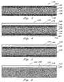
- FIG. 1is a sectional view of a first embodiment of the thermoplastic multi-layered composite structure taught by the present invention
- FIG. 2is a sectional view of the embodiment illustrated in FIG. 1 with the inner skin removed;
- FIG. 3is a sectional view of a multi-layered foam core as taught by the present invention.
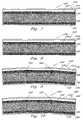
- FIG. 4is a sectional view of a second embodiment of the thermoplastic multi-layered composite structure taught by the present invention.
- FIG. 5is a sectional view of the embodiment illustrated in FIG. 4 with the inner skin removed;
- FIG. 6is a sectional view of a third embodiment of the thermoplastic multi-layered composite structure taught by the present invention shown without an inner skin;
- FIG. 7is a sectional view of an alternative second embodiment of the present invention wherein a welding or bonding process is utilized to attach the outer and inner skins to the extruded foam core rather than adhesives;
- FIG. 8is a sectional view of the embodiment shown in FIG. 7 with the inner skin removed;
- FIG. 9is a sectional view of a further alternative second embodiment of the present invention having slits through the foam core for shaping;
- FIG. 10is a sectional view of another alternative second embodiment of the present invention having slits through the foam core for shaping;
- FIG. 11is a sectional view of a first multi-layered acrylic embodiment of the present invention.
- FIG. 12is a sectional view of the first acrylic embodiment of FIG. 11 and including an acrylic inner skin layer;
- FIG. 13is a sectional view of a second multi-layered acrylic embodiment of the present invention.
- FIG. 14is a sectional view of the second acrylic embodiment of FIG. 13 and including an acrylic inner skin layer;
- FIG. 15is a sectional view of a third multi-layered acrylic embodiment of the present invention.
- FIG. 16is a sectional view of the second acrylic embodiment of FIG. 15 and including an acrylic inner skin layer;
- FIG. 17is a sectional view of a portion of an acrylic-polyvinylchloride foam in accordance with the present invention.
- FIG. 18is a sectional view of a multi-layered composite structure in accordance with all embodiments of the present invention and illustrating discrete reinforcement for the composite structure.
- FIG. 19is a sectional view illustrating the discrete reinforcement of FIG. 18 for a end-use product.
- FIGS. 1 and 2illustrate a first embodiment of a thermoplastic multi-layered composite structure in accordance with the present invention with the composite structure being generally designated as reference numeral 20 .
- Composite structure 20generally includes a top skin 22 and a foam core 30 .
- an inner or back skin 36can also be provided to help reduce fracturing of foam core 30 .
- Back skin 36can be vacuumformed during construction, however, such is not limiting.
- top skin 22consist of an acrylic polypropylene outer layer 24 and a polypropylene substrate 26 .
- An amorphous materialcan also be added to the acrylic polypropylene outer layer 24 to increase the impact strength of top skin 22 .
- substrate 26has a high melt strength.
- Top skin 22consisting of a weatherable acrylic polypropylene outer layer 24 and high melt strength substrate 26 , can also be referred to as a cap sheet.
- Outer layer 24provides a relatively hard and weatherable outer surface.
- Substrate 26is provided as backing to outer layer 24 for cost purposes. Where cost considerations are not a concern top skin 22 can alternatively be constructed solely of acrylic polypropylene.
- top skin 22can be constructed from a relatively high density polypropylene, with or without substrate 26 , and without the acrylic component in outer layer 24 .
- the density of outer layer 24is preferably higher than the density of substrate 26 .
- the high density polypropyleneprovides a hard and stiff surface, which for some uses of composite structure 20 may be sufficient without the need of an additional acrylic element or substrate 26 .
- top skin 22consisting of outer layer 24 with or without substrate 26 , is constructed by extrusion (outer layer 24 solely) or co-extrusion (outer layer 24 and substrate 26 ) procedures with top skin 22 being in the form of a planar sheet. When co-extruded, outer layer 24 and substrate 26 travel through a die where they are heated and fused together to form top skin 22 .
- outer layer 24is relatively thin as compared to substrate 26 .
- top skin 22is vacuumformed or thermoformed to its intended shape, assuming that the planar sheet form is not the intended shape.
- extruded or co-extruded top skin 22is loaded on a clamp frame and rotated in a first oven station for heating (preheat) the planar sheet.
- the preheated sheetis placed in a second oven station, which causes the sheet to sag and become molten plastic.
- a mold of the intended shapeis disposed below the sagging sheet.
- the sheetis lowered into the mold and a vacuum is applied through the base of the mold to suck the sheet about the mold.
- the pulled sheettakes the form of the mold.
- the shaped sheetis then allowed to cool and removed from the mold, to provide a top skin 22 in its intended shape.
- foam core 30is constructed from an expanded polypropylene, which forms bead like cells 32 .
- Foam core 30has a first surface and a second surface.
- a hot melt spray polypropylene adhesive 28is provided to allow top skin 22 to adhere or bond to the first surface of foam core 30 .
- adhesive 28can be an epoxy.
- a bottom or back skin 36can be attached or bonded to the second surface of foam core 30 , preferably by a polypropylene adhesive 34 which can be the same as adhesive 28 .
- Back skin 36helps to prevent foam core 30 from cracking.
- FIG. 2illustrates composite structure 20 without a back skin 36 , and thus also without adhesive 34 .
- top skin 22 , foam core 30 , back skin 36 and adhesives 28 and 34are all polypropylene based to provide a one hundred (100%) percent recyclable composite structure 20 .
- FIG. 3illustrates a multi-layer extruded polypropylene foam core 130 .
- Top skin 122 and/or back skin 152can be attached to foam core 130 through a welding or bonding process in lieu of adhesives (See FIGS. 7 and 8 ).
- FIG. 7illustrates top skin 122 and the back or inner skin 152 both attached to foam core 130 by fusing or bonding, while in FIG. 8 only a top skin 122 is provided and fused with foam core 130 .
- the polypropylene adhesives 128 and 150can also be utilized for attaching skins 122 and 152 , respectively, to extruded foam core 130 (See FIGS. 4 and 5 ).
- Adhesives 128 and 150are similar to adhesives 28 and 34 discussed above for the first embodiment of the present invention.
- Extruded foam core 130preferably, varies in density to provide a composite foam core 130 .
- the density of each layer which forms foam core 130is determined by the amount of air which was entrapped within the specific layer during its construction. The more expanded the cells of the layer are, the lower the density of such layer.
- a composite polypropylene foam core, such as foam core 130of varying densities, the multiple density foam layers are fused or bonded together, similar to the fusing or bonding of extruded foam core 130 to top skin 122 and back skin 152 .
- the various densities of the composite foam core 130are arranged such that the lowest density foam layer is provided at the center of composite core 130 and the varying density foam layers of core 130 are fused together and extend outward from the center in numerical order (i.e. lowest density layer at center of foam core 130 , highest density layer at outer surface of foam core).
- outer foam layers 132 and 136are of a higher density as compared to the density of middle layer 140 .
- Foam core 130is shown of consisting of three foam layers fused together to form a composite extruded polypropylene foam core 130 .
- the present inventionis not limited to a composite foam core consisting of three layers and any number of layers may be utilized, as may be necessary and are considered within the scope of the invention.
- each layer of foam core 130is preferably constructed from of an extruded polypropylene.
- the desired thickness for foam core 130is achieved by the fusing of a plurality of layers necessary to reach the chosen thickness value.
- FIG. 6illustrates an extruded foam core 230 which consist of a single polypropylene layer having a consistent density throughout as shown by cells 232 .
- foam core 230is shown only attached to top skin 122 by adhesive 128 it should be understood that foam core can also be attached to back skin 152 by a polypropylene adhesive.
- foam core 230can also be fused or bonded to top skin 122 or back skin 152 similar to the described above for foam core 130 . Accordingly, though not preferred, a single layer extruded foam core 230 can be substituted for multi-layer composite foam core 130 in appropriate circumstances.
- the densities of top skin 122 and back skin 152are relatively higher than the density of foam core 230 .
- foam core 130the densities of top skin 122 and back skin 152 are relatively higher than the densities of outer layers 132 and 134 of foam core 130 , which in turn are relatively higher than middle layer 140 of foam core 130 .
- Providing higher density outer skins and a low density core 30 , 130 or 230helps to reduce costs, while providing desired mechanical properties, such as a high shear gradient between the center and outside of the material.
- Top skin 122 and back skin 152are constructed similar to top skin 22 and back skin 36 discussed for the first embodiment of the present invention.
- the compositeis one hundred (100%) recyclable and eliminates concerns of toxicity.
- the present inventionprovides for a novel method of constructing composite structure 20 or 120 .
- the present inventionis also novel with respect to bonding or fusing a foam core to a weatherable polypropylene sheet, such as top skin 22 or 122 .
- the present inventionovercomes previous problems of bonding or fusing a foam core to a polypropylene sheet.
- Composite structure 20 or 120can be utilized as a replacement to fiberglass and other materials in many applications, including, but not limited to, boat hulls and decks, camper tops, coolers, etc. Furthermore, composite structure 20 or 120 absorbs a relatively higher amount of energy as compared to other materials such as fiberglass or wood. Substituting composite structure 20 or 120 for the wood or fiberglass, allows composite structure 20 or 120 to absorb fifty (50%) to sixty (60%) percent of the wave slap and impact energy, to thereby provide a relatively more comfortable and smooth boat ride. The use of composite structure 20 or 120 also reduces the amount of maintenance necessary as compared to fiberglass and improves durability. Structure 20 or 120 also has better long term cosmetically as compared to fiberglass. In addition to fiberglass and wood, structure 20 or 120 can also be utilized as a replacement for composite structures containing polyurethane or similar structures.
- FIGS. 11 and 12illustrate a first embodiment of a multi-layered acrylic composite structure in accordance with the present invention with the composite structure being generally designated as reference numeral 300 .
- Composite structure 300generally includes a top skin or layer 312 and an acrylic foam core 316 .
- an inner or back skin 320FIG. 12
- Back skin 320can be vacuumformed during construction, however, such is not limiting.
- top skin 312is constructed from an all acrylic material or sheet. An additional amorphous material can also be added to the acrylic outer layer 312 to increase the impact strength of top skin 312 .
- the acrylic outer layer 312provides a relatively hard and weatherable outer surface, while also providing a high gloss finish and scratch resistance outer surface.
- top skin 312is constructed by conventional extrusion techniques with top skin 312 being in the form of a planar sheet.
- Top skin 312 and back skin 320can be preferably attached to acrylic foam core 316 by conventional means such as an acrylic adhesive 314 and 318 , respectively.
- a multi-layered composite 340is illustrated, having an top skin 342 consisting of an acrylic and ABS alloy or layer combination 343 .
- Top skin 342is attached to an acrylic foam 346 by use of an acrylic adhesive 344 .
- a back skin 350can also be provided and is attached to an opposite surface of acrylic foam 346 by an acrylic adhesive 348 .
- Back skin 350can be constructed from acrylic or can be an acrylic-ABS alloy similar to top skin 342 .
- a multi-layered composite 370is illustrated, having an top skin 372 consisting of an acrylic and polyvinylchloride (“PVC”) alloy or layer combination 373 .
- Top skin 372can be attached to an acrylic foam 376 by use of an acrylic adhesive 374 .
- top skin 342 or 372can be attached, again by an acrylic adhesive, to a foam core 380 constructed from an acrylic-PVC alloy or combination ( FIG. 17 ).
- a back skin 384can also be provided and is attached to an opposite surface of foam 346 or 380 by an acrylic adhesive 388 .
- Back skin 384can be constructed from acrylic or can be an acrylic-PVC alloy similar to top skin 372 .
- top skins 312 , 342 and/or 372can be vacuumformed or thermoformed to its intended shape, as described above for FIGS. 1–10 , assuming that the planar sheet form is not the intended shape.
- top skin 312 , foam core 316 , back skin 320 and adhesives 314 and 318are all acrylic polypropylene based to provide a one hundred (100%) percent recyclable composite structure 300 .
- acrylic resinscan be used for the inner and outer layers, as well as the foam core.
- the densities of the outer and inner layersare preferably higher than the density of the foam core.
- the density of the outer layercan be the full or natural density of acrylic.
- the density of the foam coreranges from one pound to full or natural acrylic density.
- the foam corecan be constructed from an acrylic nitrile.
- the acrylic outer sheet and inner sheetcan be clear or opaque.
- the acrylic adhesivecan be a methacrylated acid adhesive.
- the foam corecan be bonded to the outer sheet and/or inner sheet.
- Various conventional methodscan be used to form the structure including cell cast, extrusion or continuous cell cast.
- the densities and thicknesses of the inner layer and the outer layerdo not have to be the same, though such is also possible.
- a 1 ⁇ 4′′ thicknesscan be used for the outer and inner layers and a 3 ⁇ 4′′ thickness for the foam core.
- the acrylic structureyields a very durable product.
- the acrylic structurecan be modified to be high impact, as well as a scratch resistance impact modified sheet.
- FIGS. 18 and 19illustrate a discretely reinforced composite structure 400 which can be constructed from one or more of the above described materials (i.e. polypropylene, acrylic, PVC, ABS, etc.) as well as other conventional materials and alloys.
- Structure 400consist of a continuous outer layer 402 , and a discretely provided foam core 404 and/or back skin 406 .
- foam core 404 and/or back skin 406are provided only where extra impact material is required.
- Foam core 404 and back skin 406can be attached by adhesives 408 and 410 , respectively, as well as by any other method discussed above. This configuration helps to reduce cost and time involved in producing the intended product.
Landscapes
- Laminated Bodies (AREA)
Abstract
Description
Claims (7)
Priority Applications (1)
| Application Number | Priority Date | Filing Date | Title |
|---|---|---|---|
| US10/778,329US7105073B2 (en) | 1997-04-25 | 2004-02-17 | Thermoplastic multi-layer composite structure |
Applications Claiming Priority (3)
| Application Number | Priority Date | Filing Date | Title |
|---|---|---|---|
| US08/846,143US5916672A (en) | 1997-04-25 | 1997-04-25 | Thermoplastic multi-layer composite structure |
| US09/315,390US6878437B1 (en) | 1997-04-25 | 1999-05-20 | Thermoplastic multi-layer composite structure |
| US10/778,329US7105073B2 (en) | 1997-04-25 | 2004-02-17 | Thermoplastic multi-layer composite structure |
Related Parent Applications (1)
| Application Number | Title | Priority Date | Filing Date |
|---|---|---|---|
| US09/315,390DivisionUS6878437B1 (en) | 1997-04-25 | 1999-05-20 | Thermoplastic multi-layer composite structure |
Publications (2)
| Publication Number | Publication Date |
|---|---|
| US20040265568A1 US20040265568A1 (en) | 2004-12-30 |
| US7105073B2true US7105073B2 (en) | 2006-09-12 |
Family
ID=25297066
Family Applications (4)
| Application Number | Title | Priority Date | Filing Date |
|---|---|---|---|
| US08/846,143Expired - Fee RelatedUS5916672A (en) | 1997-04-25 | 1997-04-25 | Thermoplastic multi-layer composite structure |
| US09/288,429Expired - LifetimeUS6444073B1 (en) | 1997-04-25 | 1999-04-08 | Thermoplastic multi-layer composite structure |
| US09/315,390Expired - Fee RelatedUS6878437B1 (en) | 1997-04-25 | 1999-05-20 | Thermoplastic multi-layer composite structure |
| US10/778,329Expired - Fee RelatedUS7105073B2 (en) | 1997-04-25 | 2004-02-17 | Thermoplastic multi-layer composite structure |
Family Applications Before (3)
| Application Number | Title | Priority Date | Filing Date |
|---|---|---|---|
| US08/846,143Expired - Fee RelatedUS5916672A (en) | 1997-04-25 | 1997-04-25 | Thermoplastic multi-layer composite structure |
| US09/288,429Expired - LifetimeUS6444073B1 (en) | 1997-04-25 | 1999-04-08 | Thermoplastic multi-layer composite structure |
| US09/315,390Expired - Fee RelatedUS6878437B1 (en) | 1997-04-25 | 1999-05-20 | Thermoplastic multi-layer composite structure |
Country Status (5)
| Country | Link |
|---|---|
| US (4) | US5916672A (en) |
| EP (1) | EP0977643A1 (en) |
| AU (1) | AU7157898A (en) |
| CA (1) | CA2288904C (en) |
| WO (1) | WO1998048962A2 (en) |
Cited By (3)
| Publication number | Priority date | Publication date | Assignee | Title |
|---|---|---|---|---|
| US20110000405A1 (en)* | 2006-11-28 | 2011-01-06 | Palmer/Snyder Furniture Company | Portable Table Construction and Method for Making the same. |
| US20180291634A1 (en)* | 2017-03-31 | 2018-10-11 | James Hardie Technology Limited | Fiber cement articles with ultra-smooth exterior surface and methods for manufacturing same |
| EP4169690A1 (en) | 2021-10-21 | 2023-04-26 | Brunswick Corporation | Molded products and systems and methods for making molded products |
Families Citing this family (102)
| Publication number | Priority date | Publication date | Assignee | Title |
|---|---|---|---|---|
| US6343385B1 (en)* | 1996-12-02 | 2002-02-05 | Jeffrey P. Katz | Impact absorbing protective apparatus for the frontal, temporal and occipital basilar skull |
| US6218023B1 (en)* | 1997-04-21 | 2001-04-17 | Montell North America, Inc. | Co-extruded laminate comprising at least one propylene graft copolymer layer |
| US5916672A (en)* | 1997-04-25 | 1999-06-29 | Brunswick Corporation | Thermoplastic multi-layer composite structure |
| AU6257499A (en)* | 1998-09-22 | 2000-04-10 | Brock Usa, Llc | Pads and padding for sports gear and accessories |
| US6032300A (en) | 1998-09-22 | 2000-03-07 | Brock Usa, Llc | Protective padding for sports gear |
| JP2002012093A (en)* | 2000-04-24 | 2002-01-15 | Oji Paper Co Ltd | Automotive interior ceiling molding member and automobile interior ceiling member using the same |
| US6655730B2 (en)* | 1998-10-13 | 2003-12-02 | Oji Paper Co., Ltd. | Automobile interior headliner molding or forming member and an automobile interior headliner member using the same |
| JP4265012B2 (en) | 1998-12-16 | 2009-05-20 | チッソ株式会社 | Thermoplastic resin structure |
| US6489019B1 (en) | 1999-05-19 | 2002-12-03 | Basell Poliolefine Italia S.P.A. | High surface gloss, co-extruded sheets from olefin polymer materials |
| US6306518B1 (en) | 1999-05-19 | 2001-10-23 | Montell Technology Company Bv | High surface gloss, co-extruded sheets from propylene polymer materials |
| WO2001030570A1 (en)* | 1999-10-28 | 2001-05-03 | Brunswick Corporation | Co-extruded thermoplastic laminate |
| US6830620B2 (en)* | 2000-04-14 | 2004-12-14 | Nordson Corporation | Powder coating booth containment structure |
| US6458209B1 (en)* | 2000-04-14 | 2002-10-01 | Nordson Corporation | Powder coating booth containment structure |
| US6536147B1 (en) | 2000-04-24 | 2003-03-25 | Skyline Displays, Inc. | Panel display system with wire management |
| US7662468B2 (en) | 2000-10-06 | 2010-02-16 | Brock Usa, Llc | Composite materials made from pretreated, adhesive coated beads |
| US6331028B1 (en) | 2000-10-17 | 2001-12-18 | Advance Usa, Inc. | Fiber-reinforced composite structure |
| US6627018B1 (en) | 2000-10-17 | 2003-09-30 | Advance Usa, Llc | System and method of forming composite structures |
| JP2002219726A (en)* | 2001-01-25 | 2002-08-06 | Kanegafuchi Chem Ind Co Ltd | In-mold foam molded article with skin and method for producing the same |
| US20020167136A1 (en)* | 2001-03-09 | 2002-11-14 | Lehr Gregory S. | Dual density foam core sports board |
| US6932591B2 (en) | 2001-06-28 | 2005-08-23 | Primex Plastics Corporation | Apparatus and method for co-extruding multi color plastics |
| JP2003034192A (en)* | 2001-07-25 | 2003-02-04 | Oji Paper Co Ltd | Automotive interior ceiling molding member and automotive interior ceiling member using the same |
| JP2003146051A (en)* | 2001-11-09 | 2003-05-21 | Oji Paper Co Ltd | Automotive air duct |
| USD509168S1 (en) | 2002-03-08 | 2005-09-06 | Wham-O, Inc. | Sports board for supporting a rider |
| US20040055705A1 (en)* | 2002-09-20 | 2004-03-25 | Shutic Jeffrey R. | Hybrid spray booth for powder coating systems |
| US20040058141A1 (en)* | 2002-09-20 | 2004-03-25 | Shutic Jeffrey R. | Powder coating systems |
| EP1567391B1 (en)* | 2002-12-02 | 2006-06-21 | Intier Automotive Inc. | Laminated headliner assembly and method for forming a lightweight laminated headliner |
| US20040145092A1 (en)* | 2003-01-24 | 2004-07-29 | Mccollum Robert P. | Method of making a composite molded article |
| DE20302787U1 (en)* | 2003-02-20 | 2004-04-08 | Karodur-Wirkteller Gmbh | module |
| US7314534B2 (en)* | 2003-07-23 | 2008-01-01 | Masonite Corporation | Method of making multi-ply door core, multi-ply door core, and door manufactured therewith |
| US20050042433A1 (en)* | 2003-08-20 | 2005-02-24 | Jones John M. | Liner panel having barrier layer |
| US20050089678A1 (en)* | 2003-08-20 | 2005-04-28 | Mead Steven R. | Multi-layered floorig composite including an acoustic underlayment |
| US7244477B2 (en)* | 2003-08-20 | 2007-07-17 | Brock Usa, Llc | Multi-layered sports playing field with a water draining, padding layer |
| US20050100414A1 (en)* | 2003-11-07 | 2005-05-12 | Conocophillips Company | Composite riser with integrity monitoring apparatus and method |
| US7544267B2 (en)* | 2004-01-08 | 2009-06-09 | Certainteed Corporation | Method of making insulation product having nonwoven facing |
| US7625828B2 (en)* | 2004-01-08 | 2009-12-01 | Certainteed Corporation | Insulation product having nonwoven facing |
| US7140936B2 (en)* | 2004-02-12 | 2006-11-28 | John Roberts | Island swim raft |
| US7585557B2 (en)* | 2004-02-17 | 2009-09-08 | Eastman Kodak Company | Foam core imaging element with gradient density core |
| EP1778472A1 (en)* | 2004-07-29 | 2007-05-02 | BFS Diversified Products, LLC | Construction laminates |
| US7721496B2 (en)* | 2004-08-02 | 2010-05-25 | Tac Technologies, Llc | Composite decking material and methods associated with the same |
| US8266856B2 (en) | 2004-08-02 | 2012-09-18 | Tac Technologies, Llc | Reinforced structural member and frame structures |
| US8065848B2 (en) | 2007-09-18 | 2011-11-29 | Tac Technologies, Llc | Structural member |
| JP4381941B2 (en)* | 2004-09-17 | 2009-12-09 | 王子インターパック株式会社 | Laminate for automotive interior ceiling materials |
| US7972688B2 (en)* | 2005-02-01 | 2011-07-05 | Letts John B | High density polyurethane and polyisocyanurate construction boards and composite boards |
| US8752348B2 (en) | 2005-02-25 | 2014-06-17 | Syntheon Inc. | Composite pre-formed construction articles |
| ES2389089T3 (en) | 2005-02-25 | 2012-10-23 | Nova Chemicals Inc. | Composite preformed building panels, a building and a frame upright |
| US7666258B2 (en) | 2005-02-25 | 2010-02-23 | Nova Chemicals Inc. | Lightweight compositions and articles containing such |
| WO2006102634A2 (en) | 2005-03-22 | 2006-09-28 | Nova Chemicals, Inc. | Lightweight concrete compositions |
| US20060222842A1 (en)* | 2005-03-31 | 2006-10-05 | Sealed Air Corporation (Us) | Polyolefin foam composite material |
| US8057887B2 (en)* | 2005-08-17 | 2011-11-15 | Rampart Fibers, LLC | Composite materials including high modulus polyolefin fibers |
| US7648607B2 (en)* | 2005-08-17 | 2010-01-19 | Innegrity, Llc | Methods of forming composite materials including high modulus polyolefin fibers |
| US7892633B2 (en)* | 2005-08-17 | 2011-02-22 | Innegrity, Llc | Low dielectric composite materials including high modulus polyolefin fibers |
| US9746230B2 (en) | 2006-02-24 | 2017-08-29 | Carrier Corporation | Flame retardant door for transport refrigeration unit |
| US20090126854A1 (en)* | 2006-05-09 | 2009-05-21 | Carrier Corporation | Composite cover for transport refrigeration unit and method of fabricating |
| US20070266661A1 (en)* | 2006-05-20 | 2007-11-22 | Au Vitronic Limited | Method for manufacturing of composite door panel using injection molding technology |
| US7790274B2 (en)* | 2006-08-02 | 2010-09-07 | High Impact Technology, Llc | Layered panel structure including self-bonded thermoformable and non-thermoformable layer materials |
| US7401442B2 (en)* | 2006-11-28 | 2008-07-22 | Roger A Clark | Portable panel construction and method for making the same |
| DE102006059590A1 (en)* | 2006-12-16 | 2008-06-19 | Benecke-Kaliko Ag | Thermoplastic film with foamed cover film |
| US20080166526A1 (en)* | 2007-01-08 | 2008-07-10 | Monk Russell A | Formed panel structure |
| US7677009B2 (en) | 2007-02-02 | 2010-03-16 | Nova Chemicals Inc. | Roof truss system |
| US20080245028A1 (en)* | 2007-04-05 | 2008-10-09 | High Impact Technology, L.L.C. | Thermoforming, with applied pressure and dimensional re-shaping, layered, composite-material structural panel |
| US7691311B2 (en)* | 2007-04-27 | 2010-04-06 | Vec Industries, L.L.C. | Method for manufacturing a glass fiber reinforced article, and a glass fiber reinforced article |
| TW200919298A (en)* | 2007-08-01 | 2009-05-01 | Silverbrook Res Pty Ltd | Interactive handheld scanner |
| US8048219B2 (en) | 2007-09-20 | 2011-11-01 | Nova Chemicals Inc. | Method of placing concrete |
| US20100139186A1 (en)* | 2008-12-04 | 2010-06-10 | Carlisle Intangible Company | Skylight with curb design |
| GB2466432B (en)* | 2008-12-16 | 2010-11-03 | Crompton Mouldings Ltd | A moulding method and moulding machine |
| BE1019331A5 (en)* | 2010-05-10 | 2012-06-05 | Flooring Ind Ltd Sarl | FLOOR PANEL AND METHODS FOR MANUFACTURING FLOOR PANELS. |
| US8545748B2 (en)* | 2010-08-25 | 2013-10-01 | King Abdulaziz City For Science And Technology | Building bricks including plastics |
| TW201233556A (en)* | 2010-11-24 | 2012-08-16 | Applied Ft Composite Solutions Inc | Composite cushioning material and jigless method for making the same |
| US20120244362A1 (en) | 2011-03-22 | 2012-09-27 | Pramanik Pranabes K | Multi-layer sheet structure |
| GB2506796B (en) | 2011-06-17 | 2017-03-22 | Berry Plastics Corp | Insulated container |
| AU2012363114B2 (en) | 2011-06-17 | 2016-10-06 | Berry Plastics Corporation | Insulated sleeve for a cup |
| US9067705B2 (en) | 2011-06-17 | 2015-06-30 | Berry Plastics Corporation | Process for forming an insulated container having artwork |
| WO2012174422A2 (en) | 2011-06-17 | 2012-12-20 | Berry Plastics Corporation | Insulated container with molded brim |
| EP3255098A1 (en) | 2011-08-31 | 2017-12-13 | Berry Plastics Corporation | Polymeric material for an insulated container |
| US9441921B2 (en)* | 2011-09-30 | 2016-09-13 | Black Mountain Industries, Inc. | Gunner accessory package |
| US9163908B2 (en) | 2011-09-30 | 2015-10-20 | Black Mountain Industries, Inc. | Gunner accessory package |
| WO2013053475A1 (en)* | 2011-10-11 | 2013-04-18 | Ingenieurbüro Urbanek, Pfankuche Und Partner | Sandwich element with different core properties in different regions, and method for producing same |
| CN104602895A (en) | 2012-08-07 | 2015-05-06 | 比瑞塑料公司 | Cup-forming process and machine |
| USD713600S1 (en)* | 2012-08-17 | 2014-09-16 | Traci Chesser | Wall mountable back scrubber |
| MX378138B (en) | 2012-10-26 | 2025-03-10 | Berry Plastics Corp | POLYMERIC MATERIAL FOR AN INSULATED CONTAINER. |
| AR093944A1 (en) | 2012-12-14 | 2015-07-01 | Berry Plastics Corp | PUNCHED FOR PACKAGING |
| AR093943A1 (en) | 2012-12-14 | 2015-07-01 | Berry Plastics Corp | EDGE OF A THERMAL PACK |
| US9840049B2 (en) | 2012-12-14 | 2017-12-12 | Berry Plastics Corporation | Cellular polymeric material |
| US9957365B2 (en) | 2013-03-13 | 2018-05-01 | Berry Plastics Corporation | Cellular polymeric material |
| BR112015022750A2 (en) | 2013-03-14 | 2017-07-18 | Berry Plastics Corp | container |
| US9833682B1 (en)* | 2013-08-06 | 2017-12-05 | John E. Morgan | Weight lifting drop bag |
| TW201522445A (en) | 2013-08-16 | 2015-06-16 | Berry Plastics Corp | Polymeric material for insulated containers |
| RU2016110756A (en) | 2013-08-26 | 2017-10-03 | Берри Пластикс Корпорейшн | Polymeric material for the container |
| US10214906B2 (en)* | 2014-07-09 | 2019-02-26 | Thomas L. Kelly | Reverse ballasted roof system |
| US9758655B2 (en) | 2014-09-18 | 2017-09-12 | Berry Plastics Corporation | Cellular polymeric material |
| US20160121585A1 (en)* | 2014-11-04 | 2016-05-05 | Spintech, LLC | Thermoplastic polymer repair patches and methods of using the same |
| WO2016118838A1 (en) | 2015-01-23 | 2016-07-28 | Berry Plastics Corporation | Polymeric material for an insulated container |
| US9937652B2 (en) | 2015-03-04 | 2018-04-10 | Berry Plastics Corporation | Polymeric material for container |
| US20180186043A1 (en) | 2017-01-04 | 2018-07-05 | Brunswick Corporation | Systems and Methods for Manufacturing Boat Parts |
| NL2018440B1 (en)* | 2017-02-28 | 2018-09-19 | Champion Link Int Corp | Panel suitable for assembling a waterproof floor or wall covering, method of producing a panel |
| CA3013576A1 (en) | 2017-08-08 | 2019-02-08 | Berry Global, Inc. | Insulated multi-layer sheet and method of making the same |
| CN109897212A (en)* | 2019-03-21 | 2019-06-18 | 俞国银 | A kind of surface modification technology of expanded polypropylene material |
| US11981498B2 (en) | 2019-06-28 | 2024-05-14 | Advanced Composite Structures, Llc | Thermally insulated air cargo container |
| AU2020102117B4 (en)* | 2019-11-22 | 2021-06-10 | Marine Composites IP Pty Ltd | A floatation device |
| WO2021113964A1 (en)* | 2019-12-09 | 2021-06-17 | S6 Innovations Inc. | Detachable cab for an amphibious vehicle |
| US12091239B2 (en) | 2021-11-11 | 2024-09-17 | Advanced Composite Structures, Llc | Formed structural panel with open core |
| CN114987009A (en)* | 2022-06-30 | 2022-09-02 | 国网上海市电力公司 | non-Newtonian fluid-based composite cable pipe structure |
Citations (7)
| Publication number | Priority date | Publication date | Assignee | Title |
|---|---|---|---|---|
| US4053545A (en)* | 1974-04-26 | 1977-10-11 | Standard Oil Company (Indiana) | Process for manufacturing laminated structural foam articles |
| US4256797A (en)* | 1976-09-02 | 1981-03-17 | Inmont Corporation | Contoured resilient vehicle trim panel |
| US4315050A (en) | 1980-01-25 | 1982-02-09 | Norfield Corporation | Laminates structure of an expanded core panel and a flat sheet of material which does not easily bond and a process for making the same |
| US4986860A (en)* | 1987-09-18 | 1991-01-22 | Kyowa Leather Cloth Co., Ltd. | Method for producing a laminated material |
| CA2086246A1 (en) | 1991-04-25 | 1992-10-26 | Takahisa Hara | Multilayer molded article and method for producing the same |
| US5591078A (en)* | 1995-09-29 | 1997-01-07 | Davidson Textron Inc. | Automotive interior trim having integrated defrost duct |
| US6444073B1 (en)* | 1997-04-25 | 2002-09-03 | Brunswick Corporation | Thermoplastic multi-layer composite structure |
Family Cites Families (44)
| Publication number | Priority date | Publication date | Assignee | Title |
|---|---|---|---|---|
| GB1210637A (en)* | 1969-06-21 | 1970-10-28 | Toray Industries | Thermoplastic resin foam |
| US3755063A (en)* | 1970-03-09 | 1973-08-28 | Xox Corp | Thermoformable laminated structures |
| US3936565A (en)* | 1974-05-03 | 1976-02-03 | Hollowform, Inc. | Molded plastic article and method |
| US4032689A (en)* | 1974-11-29 | 1977-06-28 | Insulex, Inc. | Construction laminate of plastic foam between paper sheets |
| US4329386A (en)* | 1974-12-30 | 1982-05-11 | Samowich Joseph J | Decorative laminate |
| US4211590A (en)* | 1978-07-21 | 1980-07-08 | Inmont Corporation | Method of making perforated contoured trim panel |
| JPS5559955A (en)* | 1978-10-30 | 1980-05-06 | Dainippon Ink & Chemicals | Interior finish material with uneven pattern that is excellent in tobacco fire resisting property |
| US4321179A (en)* | 1979-11-28 | 1982-03-23 | Nippon Oil And Fats Co., Ltd. | Process for producing an aqueous liquid dispersion of polymers |
| JPS5869021A (en)* | 1981-10-21 | 1983-04-25 | Dainippon Ink & Chem Inc | Form sheet manufacturing method |
| US4440825A (en)* | 1982-08-09 | 1984-04-03 | Uniroyal, Inc. | Laminate with skin based on AES graft copolymer |
| US4913944A (en)* | 1984-05-01 | 1990-04-03 | Old Town Canoe Company | Boat hull |
| US4579774A (en)* | 1984-10-30 | 1986-04-01 | Sekisui Kagaku Kogyo Kabushiki Kaisha | Reinforced laminate |
| KR880001033B1 (en)* | 1985-08-05 | 1988-06-15 | 니혼엑스란고오교오 가부시끼가이샤 | Acrylic fiber and it's making method |
| CA1279806C (en)* | 1986-01-28 | 1991-02-05 | Toyota Jidosha Kabushiki Kaisha | Laminated structure for interior finishing materials, and method of production |
| US4734312A (en)* | 1986-06-09 | 1988-03-29 | Honda Giken Kogyo Kabushiki Kaisha | Protective covering for automobile bodies |
| JPH0829573B2 (en)* | 1986-11-18 | 1996-03-27 | 株式会社ジェイエスピー | Thermoforming material |
| KR960000727B1 (en)* | 1988-03-01 | 1996-01-12 | 도레이 가부시끼가이샤 | Manufacturing method of molded laminate |
| US5300570A (en)* | 1989-03-01 | 1994-04-05 | Rohm And Haas Company | Plastic articles with compatibilized barrier resin |
| US5035933A (en)* | 1989-03-01 | 1991-07-30 | Rohm And Haas Company | Plastic articles with compatibilized barrier resin |
| EP0640461A1 (en)* | 1988-08-01 | 1995-03-01 | Tetra Laval Holdings & Finance SA | Method for producing a flexible creased packaging material |
| US4910067A (en)* | 1989-07-21 | 1990-03-20 | Neill Michael A O | Thermoplastic/foam core/fiber-reinforced resin structural composite material, a process for making said material and a boat structure made from said material |
| US5066531A (en)* | 1989-09-05 | 1991-11-19 | Ametek | Variable thickness foam plank |
| US5066331A (en)* | 1989-12-21 | 1991-11-19 | Westvaco Corporation | Water-soluble rosin polyamide resins |
| DE4101806A1 (en)* | 1991-01-23 | 1992-07-30 | Basf Ag | SHOCK ABSORBING PROPYLENE POLYMER COMPOSITE MOLDED PARTS |
| DE69215153T2 (en)* | 1991-07-26 | 1997-03-13 | Matsushita Electric Ind Co Ltd | Foamed polymer and process for its production |
| JP2668812B2 (en)* | 1992-01-31 | 1997-10-27 | 積水化成品工業株式会社 | Polypropylene foam sheet suitable for thermoforming |
| US5257594A (en)* | 1992-03-19 | 1993-11-02 | Methven Robert W | Suitcase boat |
| US5834082A (en)* | 1992-05-04 | 1998-11-10 | Webcore Technologies, Inc. | Reinforced foam cores and method and apparatus of production |
| JPH0648220A (en)* | 1992-06-04 | 1994-02-22 | Kanegafuchi Chem Ind Co Ltd | Instrument panel |
| JPH06115025A (en)* | 1992-10-09 | 1994-04-26 | Kanegafuchi Chem Ind Co Ltd | Automobile interior finishing material |
| US5338614A (en)* | 1992-12-22 | 1994-08-16 | Uvtec, Inc. | Polyolefin-acrylic bonded composites |
| US5401581A (en)* | 1992-12-22 | 1995-03-28 | Uvtec, Inc. | Polyolefin-acrylic bonded composite |
| US5494737A (en)* | 1992-12-28 | 1996-02-27 | Mitsui Toatsu Chemicals, Inc. | Ceiling material for vehicles and production process thereof |
| JP3297135B2 (en)* | 1993-04-21 | 2002-07-02 | 積水化学工業株式会社 | Interior skin material and interior laminate |
| DE4320636C2 (en)* | 1993-06-22 | 1999-12-02 | Magna Interior Systems Gmbh | Trim part |
| US5413660A (en)* | 1993-10-26 | 1995-05-09 | Rohm And Haas Company | Method for imparting improved adhesion to polyolefin substrates |
| JP2949046B2 (en)* | 1993-12-24 | 1999-09-13 | 株式会社ジェイエスピー | Polypropylene resin foam laminate sheet and base material for molding automotive ceiling materials |
| GB9404708D0 (en)* | 1994-03-11 | 1994-04-27 | Du Pont Canada | Polypropylene-based hot-melt adhesive |
| DE4419162A1 (en)* | 1994-06-01 | 1995-12-07 | Polarcup Gmbh | Container, partic. beaker, made of multi=layer plastic material |
| JP3088918B2 (en)* | 1994-12-21 | 2000-09-18 | 積水化成品工業株式会社 | Laminated polypropylene resin foam sheet and molded product thereof |
| JP2904337B2 (en)* | 1995-03-22 | 1999-06-14 | 株式会社ジェイエスピー | Propylene resin laminated foam sheet for molding |
| JPH09262921A (en)* | 1996-03-29 | 1997-10-07 | Sekisui Chem Co Ltd | Laminated foam for vacuum molding |
| US5876813A (en)* | 1996-07-09 | 1999-03-02 | Senitnel Products Corp | Laminated foam structures with enhanced properties |
| JPH1024540A (en)* | 1996-07-10 | 1998-01-27 | Jsp Corp | Polypropylene resin foam laminate and partitioning material comprising the laminate |
- 1997
- 1997-04-25USUS08/846,143patent/US5916672A/ennot_activeExpired - Fee Related
- 1998
- 1998-04-24AUAU71578/98Apatent/AU7157898A/ennot_activeAbandoned
- 1998-04-24EPEP19980918702patent/EP0977643A1/ennot_activeWithdrawn
- 1998-04-24WOPCT/US1998/008294patent/WO1998048962A2/ennot_activeApplication Discontinuation
- 1998-04-24CACA 2288904patent/CA2288904C/ennot_activeExpired - Fee Related
- 1999
- 1999-04-08USUS09/288,429patent/US6444073B1/ennot_activeExpired - Lifetime
- 1999-05-20USUS09/315,390patent/US6878437B1/ennot_activeExpired - Fee Related
- 2004
- 2004-02-17USUS10/778,329patent/US7105073B2/ennot_activeExpired - Fee Related
Patent Citations (7)
| Publication number | Priority date | Publication date | Assignee | Title |
|---|---|---|---|---|
| US4053545A (en)* | 1974-04-26 | 1977-10-11 | Standard Oil Company (Indiana) | Process for manufacturing laminated structural foam articles |
| US4256797A (en)* | 1976-09-02 | 1981-03-17 | Inmont Corporation | Contoured resilient vehicle trim panel |
| US4315050A (en) | 1980-01-25 | 1982-02-09 | Norfield Corporation | Laminates structure of an expanded core panel and a flat sheet of material which does not easily bond and a process for making the same |
| US4986860A (en)* | 1987-09-18 | 1991-01-22 | Kyowa Leather Cloth Co., Ltd. | Method for producing a laminated material |
| CA2086246A1 (en) | 1991-04-25 | 1992-10-26 | Takahisa Hara | Multilayer molded article and method for producing the same |
| US5591078A (en)* | 1995-09-29 | 1997-01-07 | Davidson Textron Inc. | Automotive interior trim having integrated defrost duct |
| US6444073B1 (en)* | 1997-04-25 | 2002-09-03 | Brunswick Corporation | Thermoplastic multi-layer composite structure |
Cited By (5)
| Publication number | Priority date | Publication date | Assignee | Title |
|---|---|---|---|---|
| US20110000405A1 (en)* | 2006-11-28 | 2011-01-06 | Palmer/Snyder Furniture Company | Portable Table Construction and Method for Making the same. |
| US8316602B2 (en) | 2006-11-28 | 2012-11-27 | Ps Furniture, Inc. | Portable table construction and method for making the same |
| US20180291634A1 (en)* | 2017-03-31 | 2018-10-11 | James Hardie Technology Limited | Fiber cement articles with ultra-smooth exterior surface and methods for manufacturing same |
| US10590657B2 (en)* | 2017-03-31 | 2020-03-17 | James Hardie Technology Limited | Fiber cement articles with ultra-smooth exterior surface and methods for manufacturing same |
| EP4169690A1 (en) | 2021-10-21 | 2023-04-26 | Brunswick Corporation | Molded products and systems and methods for making molded products |
Also Published As
| Publication number | Publication date |
|---|---|
| AU7157898A (en) | 1998-11-24 |
| US6444073B1 (en) | 2002-09-03 |
| EP0977643A1 (en) | 2000-02-09 |
| WO1998048962B1 (en) | 1999-07-22 |
| WO1998048962A2 (en) | 1998-11-05 |
| CA2288904C (en) | 2009-02-03 |
| US6878437B1 (en) | 2005-04-12 |
| US20040265568A1 (en) | 2004-12-30 |
| CA2288904A1 (en) | 1998-11-05 |
| US5916672A (en) | 1999-06-29 |
| WO1998048962A3 (en) | 1999-01-28 |
Similar Documents
| Publication | Publication Date | Title |
|---|---|---|
| US7105073B2 (en) | Thermoplastic multi-layer composite structure | |
| EP0269148B1 (en) | A method of making a shaped article from a sandwich construction | |
| US7344667B2 (en) | Prepreg, production process thereof, and molded article | |
| KR102271926B1 (en) | Resin expanded particles, resin expanded molded article, and laminate | |
| US8889574B2 (en) | Foam laminate product and process for production thereof | |
| US3884169A (en) | Marginal zone reinforcing system for the production of heavy duty foam resin constructions | |
| IE843325L (en) | Moulded fibre - reinforced articles. | |
| KR20010043812A (en) | Vehicle headliner comprised of a thermoformable thermoplastic foam sheet | |
| US5562791A (en) | Method of producing a thermoplastic sandwich plate | |
| US5374383A (en) | Method of forming an article consisting of a foam core and one or more covering layers | |
| KR970701231A (en) | Thermoplastic Resin Foam and Method of Production Thereof | |
| GB1582696A (en) | Method of producing reinforced plastic panels | |
| WO1999065661A1 (en) | Coated, long fiber reinforcing composite structure and process of preparation thereof | |
| CA2724185A1 (en) | Foam laminate product and process for production thereof | |
| CN104554064A (en) | Wet PU + GF headliner substrate with acoustic function | |
| JPH08187827A (en) | Apparatus for manufacture of composite panel | |
| US20230405980A1 (en) | Low-Density Foam at Least Partially Covered with a Skin Material | |
| JP2578190B2 (en) | Long composite molding | |
| GB2282829A (en) | Sound absorbing member | |
| JPH0839712A (en) | Production of foamed structure | |
| JPH06136646A (en) | Lightweight composite material and its production | |
| MXPA00011695A (en) | Vehicle headliner comprised of a thermoformable thermoplastic foam sheet | |
| JPH08267475A (en) | Manufacture of fiber-reinforced thermoplastic resin foam | |
| Reinke | Heat vuicanizable polysiloxane compositions containing asbestos | |
| JPH04278335A (en) | Manufacture of lightweight composite molded article |
Legal Events
| Date | Code | Title | Description |
|---|---|---|---|
| FEPP | Fee payment procedure | Free format text:PAYOR NUMBER ASSIGNED (ORIGINAL EVENT CODE: ASPN); ENTITY STATUS OF PATENT OWNER: LARGE ENTITY | |
| AS | Assignment | Owner name:JPMORGAN CHASE BANK, N.A., TEXAS Free format text:SECURITY AGREEMENT;ASSIGNORS:BRUNSWICK CORPORATION;TRITON BOAT COMPANY, L.P.;ATTWOOD CORPORATION;AND OTHERS;REEL/FRAME:022092/0365 Effective date:20081219 Owner name:JPMORGAN CHASE BANK, N.A.,TEXAS Free format text:SECURITY AGREEMENT;ASSIGNORS:BRUNSWICK CORPORATION;TRITON BOAT COMPANY, L.P.;ATTWOOD CORPORATION;AND OTHERS;REEL/FRAME:022092/0365 Effective date:20081219 | |
| AS | Assignment | Owner name:THE BANK OF NEW YORK MELLON TRUST COMPANY, N.A., I Free format text:SECURITY AGREEMENT;ASSIGNORS:BRUNSWICK CORPORATION;ATTWOOD CORPORATION;BOSTON WHALER, INC.;AND OTHERS;REEL/FRAME:023180/0493 Effective date:20090814 Owner name:THE BANK OF NEW YORK MELLON TRUST COMPANY, N.A.,IL Free format text:SECURITY AGREEMENT;ASSIGNORS:BRUNSWICK CORPORATION;ATTWOOD CORPORATION;BOSTON WHALER, INC.;AND OTHERS;REEL/FRAME:023180/0493 Effective date:20090814 | |
| FPAY | Fee payment | Year of fee payment:4 | |
| AS | Assignment | Owner name:BOSTON WHALER, INC., FLORIDA Free format text:RELEASE BY SECURED PARTY;ASSIGNOR:JPMORGAN CHASE BANK, N.A., AS ADMINISTRATIVE AGENT;REEL/FRAME:026026/0001 Effective date:20110321 Owner name:BRUNSWICK LEISURE BOAT COMPANY, LLC, INDIANA Free format text:RELEASE BY SECURED PARTY;ASSIGNOR:JPMORGAN CHASE BANK, N.A., AS ADMINISTRATIVE AGENT;REEL/FRAME:026026/0001 Effective date:20110321 Owner name:BRUNSWICK FAMILY BOAT CO. INC., WASHINGTON Free format text:RELEASE BY SECURED PARTY;ASSIGNOR:JPMORGAN CHASE BANK, N.A., AS ADMINISTRATIVE AGENT;REEL/FRAME:026026/0001 Effective date:20110321 Owner name:LUND BOAT COMPANY, MINNESOTA Free format text:RELEASE BY SECURED PARTY;ASSIGNOR:JPMORGAN CHASE BANK, N.A., AS ADMINISTRATIVE AGENT;REEL/FRAME:026026/0001 Effective date:20110321 Owner name:BRUNSWICK COMMERICAL & GOVERNMENT PRODUCTS, INC., Free format text:RELEASE BY SECURED PARTY;ASSIGNOR:JPMORGAN CHASE BANK, N.A., AS ADMINISTRATIVE AGENT;REEL/FRAME:026026/0001 Effective date:20110321 Owner name:BRUNSWICK CORPORATION, ILLINOIS Free format text:RELEASE BY SECURED PARTY;ASSIGNOR:JPMORGAN CHASE BANK, N.A., AS ADMINISTRATIVE AGENT;REEL/FRAME:026026/0001 Effective date:20110321 Owner name:TRITON BOAT COMPANY, L.P., TENNESSEE Free format text:RELEASE BY SECURED PARTY;ASSIGNOR:JPMORGAN CHASE BANK, N.A., AS ADMINISTRATIVE AGENT;REEL/FRAME:026026/0001 Effective date:20110321 Owner name:ATTWOOD CORPORATION, MICHIGAN Free format text:RELEASE BY SECURED PARTY;ASSIGNOR:JPMORGAN CHASE BANK, N.A., AS ADMINISTRATIVE AGENT;REEL/FRAME:026026/0001 Effective date:20110321 Owner name:BRUNSWICK BOWLING & BILLIARDS CORPORATION, ILLINOI Free format text:RELEASE BY SECURED PARTY;ASSIGNOR:JPMORGAN CHASE BANK, N.A., AS ADMINISTRATIVE AGENT;REEL/FRAME:026026/0001 Effective date:20110321 Owner name:LAND 'N' SEA DISTRIBUTING, INC., FLORIDA Free format text:RELEASE BY SECURED PARTY;ASSIGNOR:JPMORGAN CHASE BANK, N.A., AS ADMINISTRATIVE AGENT;REEL/FRAME:026026/0001 Effective date:20110321 | |
| AS | Assignment | Owner name:JPMORGAN CHASE BANK, N.A., AS ADMINISTRATIVE AGENT Free format text:SECURITY AGREEMENT;ASSIGNORS:BRUNSWICK CORPORATION;ATTWOOD CORPORATION;BOSTON WHALER, INC.;AND OTHERS;REEL/FRAME:026072/0239 Effective date:20110321 | |
| AS | Assignment | Owner name:BRUNSWICK CORPORATION, ILLINOIS Free format text:RELEASE BY SECURED PARTY;ASSIGNOR:THE BANK OF NEW YORK MELLON;REEL/FRAME:031973/0242 Effective date:20130717 | |
| FPAY | Fee payment | Year of fee payment:8 | |
| AS | Assignment | Owner name:LUND BOAT COMPANY, ILLINOIS Free format text:RELEASE BY SECURED PARTY;ASSIGNOR:JPMORGAN CHASE BANK, N.A.;REEL/FRAME:034794/0300 Effective date:20141226 Owner name:BRUNSWICK BOWLING & BILLIARDS CORPORATION, ILLINOI Free format text:RELEASE BY SECURED PARTY;ASSIGNOR:JPMORGAN CHASE BANK, N.A.;REEL/FRAME:034794/0300 Effective date:20141226 Owner name:BRUNSWICK LEISURE BOAT COMPANY, LLC, ILLINOIS Free format text:RELEASE BY SECURED PARTY;ASSIGNOR:JPMORGAN CHASE BANK, N.A.;REEL/FRAME:034794/0300 Effective date:20141226 Owner name:ATTWOOD CORPORATION, ILLINOIS Free format text:RELEASE BY SECURED PARTY;ASSIGNOR:JPMORGAN CHASE BANK, N.A.;REEL/FRAME:034794/0300 Effective date:20141226 Owner name:BRUNSWICK FAMILY BOAT CO. INC., ILLINOIS Free format text:RELEASE BY SECURED PARTY;ASSIGNOR:JPMORGAN CHASE BANK, N.A.;REEL/FRAME:034794/0300 Effective date:20141226 Owner name:BRUNSWICK COMMERCIAL & GOVERNMENT PRODUCTS, INC., Free format text:RELEASE BY SECURED PARTY;ASSIGNOR:JPMORGAN CHASE BANK, N.A.;REEL/FRAME:034794/0300 Effective date:20141226 Owner name:BOSTON WHALER, INC., ILLINOIS Free format text:RELEASE BY SECURED PARTY;ASSIGNOR:JPMORGAN CHASE BANK, N.A.;REEL/FRAME:034794/0300 Effective date:20141226 Owner name:BRUNSWICK CORPORATION, ILLINOIS Free format text:RELEASE BY SECURED PARTY;ASSIGNOR:JPMORGAN CHASE BANK, N.A.;REEL/FRAME:034794/0300 Effective date:20141226 Owner name:LAND 'N' SEA DISTRIBUTING, INC., ILLINOIS Free format text:RELEASE BY SECURED PARTY;ASSIGNOR:JPMORGAN CHASE BANK, N.A.;REEL/FRAME:034794/0300 Effective date:20141226 | |
| FEPP | Fee payment procedure | Free format text:MAINTENANCE FEE REMINDER MAILED (ORIGINAL EVENT CODE: REM.) | |
| LAPS | Lapse for failure to pay maintenance fees | Free format text:PATENT EXPIRED FOR FAILURE TO PAY MAINTENANCE FEES (ORIGINAL EVENT CODE: EXP.); ENTITY STATUS OF PATENT OWNER: LARGE ENTITY | |
| STCH | Information on status: patent discontinuation | Free format text:PATENT EXPIRED DUE TO NONPAYMENT OF MAINTENANCE FEES UNDER 37 CFR 1.362 | |
| FP | Lapsed due to failure to pay maintenance fee | Effective date:20180912 |