US7105033B2 - Hydrogen gas generation system - Google Patents
Hydrogen gas generation systemDownload PDFInfo
- Publication number
- US7105033B2 US7105033B2US10/359,104US35910403AUS7105033B2US 7105033 B2US7105033 B2US 7105033B2US 35910403 AUS35910403 AUS 35910403AUS 7105033 B2US7105033 B2US 7105033B2
- Authority
- US
- United States
- Prior art keywords
- fuel
- hydrogen
- hydrogen gas
- chamber
- permeable membrane
- Prior art date
- Legal status (The legal status is an assumption and is not a legal conclusion. Google has not performed a legal analysis and makes no representation as to the accuracy of the status listed.)
- Expired - Fee Related, expires
Links
Images


Classifications
- C—CHEMISTRY; METALLURGY
- C01—INORGANIC CHEMISTRY
- C01B—NON-METALLIC ELEMENTS; COMPOUNDS THEREOF; METALLOIDS OR COMPOUNDS THEREOF NOT COVERED BY SUBCLASS C01C
- C01B3/00—Hydrogen; Gaseous mixtures containing hydrogen; Separation of hydrogen from mixtures containing it; Purification of hydrogen
- C01B3/02—Production of hydrogen or of gaseous mixtures containing a substantial proportion of hydrogen
- C01B3/22—Production of hydrogen or of gaseous mixtures containing a substantial proportion of hydrogen by decomposition of gaseous or liquid organic compounds
- C01B3/24—Production of hydrogen or of gaseous mixtures containing a substantial proportion of hydrogen by decomposition of gaseous or liquid organic compounds of hydrocarbons
- C01B3/26—Production of hydrogen or of gaseous mixtures containing a substantial proportion of hydrogen by decomposition of gaseous or liquid organic compounds of hydrocarbons using catalysts
- C—CHEMISTRY; METALLURGY
- C01—INORGANIC CHEMISTRY
- C01B—NON-METALLIC ELEMENTS; COMPOUNDS THEREOF; METALLOIDS OR COMPOUNDS THEREOF NOT COVERED BY SUBCLASS C01C
- C01B3/00—Hydrogen; Gaseous mixtures containing hydrogen; Separation of hydrogen from mixtures containing it; Purification of hydrogen
- C01B3/02—Production of hydrogen or of gaseous mixtures containing a substantial proportion of hydrogen
- C01B3/06—Production of hydrogen or of gaseous mixtures containing a substantial proportion of hydrogen by reaction of inorganic compounds containing electro-positively bound hydrogen, e.g. water, acids, bases, ammonia, with inorganic reducing agents
- C01B3/065—Production of hydrogen or of gaseous mixtures containing a substantial proportion of hydrogen by reaction of inorganic compounds containing electro-positively bound hydrogen, e.g. water, acids, bases, ammonia, with inorganic reducing agents from a hydride
- B—PERFORMING OPERATIONS; TRANSPORTING
- B01—PHYSICAL OR CHEMICAL PROCESSES OR APPARATUS IN GENERAL
- B01J—CHEMICAL OR PHYSICAL PROCESSES, e.g. CATALYSIS OR COLLOID CHEMISTRY; THEIR RELEVANT APPARATUS
- B01J7/00—Apparatus for generating gases
- B01J7/02—Apparatus for generating gases by wet methods
- C—CHEMISTRY; METALLURGY
- C01—INORGANIC CHEMISTRY
- C01B—NON-METALLIC ELEMENTS; COMPOUNDS THEREOF; METALLOIDS OR COMPOUNDS THEREOF NOT COVERED BY SUBCLASS C01C
- C01B3/00—Hydrogen; Gaseous mixtures containing hydrogen; Separation of hydrogen from mixtures containing it; Purification of hydrogen
- C01B3/02—Production of hydrogen or of gaseous mixtures containing a substantial proportion of hydrogen
- C01B3/06—Production of hydrogen or of gaseous mixtures containing a substantial proportion of hydrogen by reaction of inorganic compounds containing electro-positively bound hydrogen, e.g. water, acids, bases, ammonia, with inorganic reducing agents
- C—CHEMISTRY; METALLURGY
- C01—INORGANIC CHEMISTRY
- C01B—NON-METALLIC ELEMENTS; COMPOUNDS THEREOF; METALLOIDS OR COMPOUNDS THEREOF NOT COVERED BY SUBCLASS C01C
- C01B3/00—Hydrogen; Gaseous mixtures containing hydrogen; Separation of hydrogen from mixtures containing it; Purification of hydrogen
- C01B3/02—Production of hydrogen or of gaseous mixtures containing a substantial proportion of hydrogen
- C01B3/32—Production of hydrogen or of gaseous mixtures containing a substantial proportion of hydrogen by reaction of gaseous or liquid organic compounds with gasifying agents, e.g. water, carbon dioxide, air
- C01B3/34—Production of hydrogen or of gaseous mixtures containing a substantial proportion of hydrogen by reaction of gaseous or liquid organic compounds with gasifying agents, e.g. water, carbon dioxide, air by reaction of hydrocarbons with gasifying agents
- C01B3/38—Production of hydrogen or of gaseous mixtures containing a substantial proportion of hydrogen by reaction of gaseous or liquid organic compounds with gasifying agents, e.g. water, carbon dioxide, air by reaction of hydrocarbons with gasifying agents using catalysts
- C—CHEMISTRY; METALLURGY
- C01—INORGANIC CHEMISTRY
- C01B—NON-METALLIC ELEMENTS; COMPOUNDS THEREOF; METALLOIDS OR COMPOUNDS THEREOF NOT COVERED BY SUBCLASS C01C
- C01B3/00—Hydrogen; Gaseous mixtures containing hydrogen; Separation of hydrogen from mixtures containing it; Purification of hydrogen
- C01B3/50—Separation of hydrogen or hydrogen containing gases from gaseous mixtures, e.g. purification
- C01B3/501—Separation of hydrogen or hydrogen containing gases from gaseous mixtures, e.g. purification by diffusion
- F—MECHANICAL ENGINEERING; LIGHTING; HEATING; WEAPONS; BLASTING
- F17—STORING OR DISTRIBUTING GASES OR LIQUIDS
- F17C—VESSELS FOR CONTAINING OR STORING COMPRESSED, LIQUEFIED OR SOLIDIFIED GASES; FIXED-CAPACITY GAS-HOLDERS; FILLING VESSELS WITH, OR DISCHARGING FROM VESSELS, COMPRESSED, LIQUEFIED, OR SOLIDIFIED GASES
- F17C11/00—Use of gas-solvents or gas-sorbents in vessels
- F17C11/005—Use of gas-solvents or gas-sorbents in vessels for hydrogen
- C—CHEMISTRY; METALLURGY
- C01—INORGANIC CHEMISTRY
- C01B—NON-METALLIC ELEMENTS; COMPOUNDS THEREOF; METALLOIDS OR COMPOUNDS THEREOF NOT COVERED BY SUBCLASS C01C
- C01B2203/00—Integrated processes for the production of hydrogen or synthesis gas
- C01B2203/04—Integrated processes for the production of hydrogen or synthesis gas containing a purification step for the hydrogen or the synthesis gas
- C01B2203/0405—Purification by membrane separation
- C—CHEMISTRY; METALLURGY
- C01—INORGANIC CHEMISTRY
- C01B—NON-METALLIC ELEMENTS; COMPOUNDS THEREOF; METALLOIDS OR COMPOUNDS THEREOF NOT COVERED BY SUBCLASS C01C
- C01B2203/00—Integrated processes for the production of hydrogen or synthesis gas
- C01B2203/04—Integrated processes for the production of hydrogen or synthesis gas containing a purification step for the hydrogen or the synthesis gas
- C01B2203/0465—Composition of the impurity
- C01B2203/0495—Composition of the impurity the impurity being water
- H—ELECTRICITY
- H01—ELECTRIC ELEMENTS
- H01M—PROCESSES OR MEANS, e.g. BATTERIES, FOR THE DIRECT CONVERSION OF CHEMICAL ENERGY INTO ELECTRICAL ENERGY
- H01M8/00—Fuel cells; Manufacture thereof
- H01M8/04—Auxiliary arrangements, e.g. for control of pressure or for circulation of fluids
- H01M8/04082—Arrangements for control of reactant parameters, e.g. pressure or concentration
- H01M8/04201—Reactant storage and supply, e.g. means for feeding, pipes
- H01M8/04208—Cartridges, cryogenic media or cryogenic reservoirs
- H—ELECTRICITY
- H01—ELECTRIC ELEMENTS
- H01M—PROCESSES OR MEANS, e.g. BATTERIES, FOR THE DIRECT CONVERSION OF CHEMICAL ENERGY INTO ELECTRICAL ENERGY
- H01M8/00—Fuel cells; Manufacture thereof
- H01M8/04—Auxiliary arrangements, e.g. for control of pressure or for circulation of fluids
- H01M8/04082—Arrangements for control of reactant parameters, e.g. pressure or concentration
- H01M8/04201—Reactant storage and supply, e.g. means for feeding, pipes
- H01M8/04216—Reactant storage and supply, e.g. means for feeding, pipes characterised by the choice for a specific material, e.g. carbon, hydride, absorbent
- H—ELECTRICITY
- H01—ELECTRIC ELEMENTS
- H01M—PROCESSES OR MEANS, e.g. BATTERIES, FOR THE DIRECT CONVERSION OF CHEMICAL ENERGY INTO ELECTRICAL ENERGY
- H01M8/00—Fuel cells; Manufacture thereof
- H01M8/06—Combination of fuel cells with means for production of reactants or for treatment of residues
- H01M8/0606—Combination of fuel cells with means for production of reactants or for treatment of residues with means for production of gaseous reactants
- H01M8/065—Combination of fuel cells with means for production of reactants or for treatment of residues with means for production of gaseous reactants by dissolution of metals or alloys; by dehydriding metallic substances
- H—ELECTRICITY
- H01—ELECTRIC ELEMENTS
- H01M—PROCESSES OR MEANS, e.g. BATTERIES, FOR THE DIRECT CONVERSION OF CHEMICAL ENERGY INTO ELECTRICAL ENERGY
- H01M8/00—Fuel cells; Manufacture thereof
- H01M8/06—Combination of fuel cells with means for production of reactants or for treatment of residues
- H01M8/0662—Treatment of gaseous reactants or gaseous residues, e.g. cleaning
- Y—GENERAL TAGGING OF NEW TECHNOLOGICAL DEVELOPMENTS; GENERAL TAGGING OF CROSS-SECTIONAL TECHNOLOGIES SPANNING OVER SEVERAL SECTIONS OF THE IPC; TECHNICAL SUBJECTS COVERED BY FORMER USPC CROSS-REFERENCE ART COLLECTIONS [XRACs] AND DIGESTS
- Y02—TECHNOLOGIES OR APPLICATIONS FOR MITIGATION OR ADAPTATION AGAINST CLIMATE CHANGE
- Y02E—REDUCTION OF GREENHOUSE GAS [GHG] EMISSIONS, RELATED TO ENERGY GENERATION, TRANSMISSION OR DISTRIBUTION
- Y02E60/00—Enabling technologies; Technologies with a potential or indirect contribution to GHG emissions mitigation
- Y02E60/30—Hydrogen technology
- Y02E60/32—Hydrogen storage
- Y—GENERAL TAGGING OF NEW TECHNOLOGICAL DEVELOPMENTS; GENERAL TAGGING OF CROSS-SECTIONAL TECHNOLOGIES SPANNING OVER SEVERAL SECTIONS OF THE IPC; TECHNICAL SUBJECTS COVERED BY FORMER USPC CROSS-REFERENCE ART COLLECTIONS [XRACs] AND DIGESTS
- Y02—TECHNOLOGIES OR APPLICATIONS FOR MITIGATION OR ADAPTATION AGAINST CLIMATE CHANGE
- Y02E—REDUCTION OF GREENHOUSE GAS [GHG] EMISSIONS, RELATED TO ENERGY GENERATION, TRANSMISSION OR DISTRIBUTION
- Y02E60/00—Enabling technologies; Technologies with a potential or indirect contribution to GHG emissions mitigation
- Y02E60/30—Hydrogen technology
- Y02E60/36—Hydrogen production from non-carbon containing sources, e.g. by water electrolysis
- Y—GENERAL TAGGING OF NEW TECHNOLOGICAL DEVELOPMENTS; GENERAL TAGGING OF CROSS-SECTIONAL TECHNOLOGIES SPANNING OVER SEVERAL SECTIONS OF THE IPC; TECHNICAL SUBJECTS COVERED BY FORMER USPC CROSS-REFERENCE ART COLLECTIONS [XRACs] AND DIGESTS
- Y02—TECHNOLOGIES OR APPLICATIONS FOR MITIGATION OR ADAPTATION AGAINST CLIMATE CHANGE
- Y02E—REDUCTION OF GREENHOUSE GAS [GHG] EMISSIONS, RELATED TO ENERGY GENERATION, TRANSMISSION OR DISTRIBUTION
- Y02E60/00—Enabling technologies; Technologies with a potential or indirect contribution to GHG emissions mitigation
- Y02E60/30—Hydrogen technology
- Y02E60/50—Fuel cells
Definitions
- the inventionrelates to a system for generating hydrogen gas using a catalyst from a fuel such as borohydride. More particularly, the invention relates to a system for hydrogen generation having a volume-exchange system for the storage of fuel solution and discharged product and a hydrogen filtration system.
- Hydrogenis a “clean fuel” because it can be reacted with oxygen in hydrogen-consuming devices, such as a fuel cell or combustion engine, to produce energy and water. Virtually no other reaction byproducts are produced in the exhaust.
- hydrogenas a fuel effectively solves many environmental problems associated with the use of petroleum based fuels. Safe and efficient storage of hydrogen gas is, therefore, essential for many applications that can use hydrogen. In particular, minimizing volume, weight and complexity of the hydrogen storage systems are important factors in mobile applications.
- a hydrogen fuel cell for small applicationsneeds to be compact and lightweight, have a high gravimetric hydrogen storage density, and be operable in any orientation. Additionally, it should be easy to match the control of the system's hydrogen flow rate and pressure to the operating demands of the fuel cell.
- Alternatives for hydrogen storage and generationinclude the class of compounds known as chemical hydrides, such as the alkali metal hydrides, the alkali metal aluminum hydrides and the alkali metal borohydrides.
- chemical hydridessuch as the alkali metal hydrides, the alkali metal aluminum hydrides and the alkali metal borohydrides.
- NaBH4sodium borohydride
- An object of the present inventionis to provide a portable hydrogen generator that incorporates a volume-exchange tank for the storage of the fuel solution and the discharged product and includes a hydrogen filtration system.
- This deviceis orientation independent and compact. Further, such a generator can utilize a throttle valve that will enable the generator to self-regulate fuel flow and hydrogen production.
- the borate solutionis usually discharged at a higher temperature than the fuel solution; the movable partition can be designed as a heat insulator to prevent heat exchange between the two regions. This design does not, however, provide for orientation independent operation.
- the metal hydride fuel component of the disclosed systemis a complex metal hydride that is water soluble and stable in aqueous solution.
- suitable metal hydridesare those having the general formula MBH4 where M is an alkali or alkaline earth metal selected from Group I or Group 2 of the periodic table, such as lithium, sodium, potassium, calcium and magnesium. Examples of such compounds include, without limitation, NaBH 4 , LiBH 4 , KBH 4 , Ca(BH 4 ) 2 and Mg(BH 4 ) 2 .
- These metal hydridesmay be utilized in mixtures, but are preferable utilized individually.
- Preferred for such systems in accordance with the present inventionis sodium borohydride (NaBH 4 ).
- NaBH 4sodium borohydride
- Sodium borohydridecan be dissolved in alkaline water solutions with virtually no reaction and the aqueous SBH fuel solutions are non-volatile and will not burn. This imparts handling and transport ease both in the bulk sense and within the hydrogen generator itself.
- a borohydride compoundwill react with water to produce hydrogen gas and a borate in accordance with the following chemical reaction:
- MBH 4 and MBO 2represent a metal borohydride and a metal metaborate.
- the rate of decomposition of the metal borohydride into hydrogen gas and a metal metaborateis pH dependent, with higher pH values hindering the hydrolysis.
- a stabilizersuch as sodium hydroxide (NaOH)
- NaOHsodium hydroxide
- a complex metal hydridesuch as sodium borohydride
- a catalyste.g. acids or a variety of transition metals
- Transition metals from the nickel, cobalt and iron familiesgenerally show the highest activity, and the metals or the corresponding metal salts or metal borides can be used in solution or as suspensions, or such salts, borides or metals can be supported on inert substrates.
- a solid catalysteither as a solid metal or metal boride or as deposited on a substrate, is contained within the catalyst chamber.
- Resulting products of the hydrogen generation processcan include hydrogen gas, borate and water among other things. It can be appreciated that the specific dimensions as well as operating temperatures and pressures of the system can be modified and adapted according to the intended use of the system and according to the specific metal hydride solution to be used without departing from the intended purpose of the invention.
- the present inventionincludes a hydrogen gas generation system with a housing having a hydrogen separation chamber and fuel storage chamber and where either or both of those chambers may include a gas permeable member to pass hydrogen through the membrane.
- a volume exchanging containerhaving a fuel storage chamber and a hydrogen separation chamber and either or both of those chambers may have a gas permeable membrane located therein.
- a fuel containerfor containing the fuel material and which may have a gas permeable membrane located therein to separate any hydrogen gas from this material.
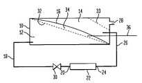
- FIG. 1is a schematic illustration of an arrangement for a hydrogen gas generation system in accordance with the invention
- FIG. 2is a schematic illustration of an alternative embodiment of a hydrogen gas generation system
- FIG. 3is a schematic illustration of a still further embodiment of a hydrogen gas generation system in accordance with the present invention.
- the hydrogen gas generation systemincludes a housing 10 which can be constructed of a relatively strong material as is necessary to carry out the purposes of the present invention.
- a fuel storage chamber 12Within the housing 10 there is formed a fuel storage chamber 12 and a hydrogen separation chamber 14 separated by a flexible partition 16 .
- the fuel storage chamber 12normally contains the fuel solution that is reactive to produce hydrogen gas and is a hydride solution and can be a stabilized metal hydride solution, such as sodium borohydride.
- the flexible partition 16can be a ribbon spring or a preformed piece of flexible plastic or similar material that has an intrinsic tension and can maintain an applied pressure on the fuel solution within the fuel storage chamber 12 .
- the flexible partition 16When the fuel storage chamber 12 is full of the fuel solution, the flexible partition 16 is expanded into a high energy “extended” state. As the flexible partition 16 contracts as the fuel solution is depleted, the flexible partition 16 returns to its lowest energy “original” state, it compresses the fuel solution and forces that fuel solution out of the fuel storage chamber and into the fuel conduit 18 .
- the fuel conduit 18conducts the fuel solution from the fuel storage chamber 12 to an inlet 20 in the catalyst chamber 22 which contains the catalyst to enhance the reaction of the fuel solution to produce hydrogen gas.
- the catalyst used with this embodimentcan comprise various catalysts known to be useful for the present application and can be ruthenium metal deposited on a metal mesh prepared as described in PCT Publication No. WO 01/51410 and entitled “System For Hydrogen Generation”.
- the reactionresults in the generation of hydrogen gas along with the formation of other materials such as borate and water and which shall simply be referred to as discharged fuel. That discharged fuel along with hydrogen thereby produced leaves the catalyst chamber 22 via an outlet 24 and passes through an outlet conduit 26 where the discharged fuel and hydrogen enters the hydrogen separation chamber 14 .
- the hydrogen gasseparates from the discharged fuel and passes upwardly to exit from the hydrogen separation chamber 14 through the hydrogen gas outlet 28 where the hydrogen is collected and channeled to an end use device to derive the energy from the hydrogen gas.
- a fuel shut off valve 30may be present in the fuel conduit 18 to act to shut off and/or control the flow of fuel solution passing from the fuel storage chamber 14 to the catalyst chamber 22 and impart manual or automated control over the production of hydrogen gas.
- first gas permeable membrane 32located in the fuel storage chamber 12 in the upper area thereof and which allows hydrogen gas to pass through the gas permeable membrane 32 while preventing the fuel solution from passing therethrough.
- suitable gas permeable membranesinclude those materials known to be more permeable to hydrogen than water such as silicon rubber, fluoropolymers or any of the common hydrogen-permeable metal membranes such as palladium-gold alloys.
- a second gas permeable membrane 33is also preferably located in the hydrogen separation chamber 14 to allow the hydrogen in that chamber to pass through the second gas permeable membrane 33 and outwardly through the hydrogen gas outlet 28 while preventing any of the discharged fuel from passing therethrough such that the discharged fuel is contained within the hydrogen separation chamber 14 so that the hydrogen gas can be recovered through the hydrogen gas outlet 28 for use with the end utilization device.
- the gaseous hydrogenis separated from the discharged fuel by means of gravity in the hydrogen separation chamber 14 and the gaseous hydrogen leaves the hydrogen separation chamber 14 through the second gas permeable membrane 33 and the hydrogen gas outlet 28 for use in supplying energy to an end utilization device, such as a fuel cell in a laptop computer or a cell phone.
- the flexible partition 16exerts a force within the fuel storage chamber 12 to initialize the reaction by forcing the fuel solution through the catalyst chamber 22 to produce the hydrogen gas and the discharged fuel.
- the discharged fuelenters the hydrogen separation chamber 14 and the discharged fuel adds weight to the flexible partition 16 to continue to force the fuel solution outwardly from the fuel storage chamber 12 through the catalyst chamber 22 as the production of hydrogen gas continues.
- the housing 10also has formed therein a fuel storage chamber 12 and a hydrogen separation chamber 14 .
- a movable partition 38that is located intermediate the fuel storage chamber 12 and the hydrogen separation chamber 14 and which is movably positioned within the housing 10 .
- first flexible bag 40comprised of a plastic material, such as nylon, and which contains the fuel solution that is discharged via an outlet 42 in the first flexible bag 40 so that the fuel solution can enter the fuel conduit 18 and the catalyst chamber 22 where the reaction takes place and the discharged fuel along with hydrogen gas passes through the outlet conduit 26 where it enters a inlet 44 in a second flexible bag 46 .
- the second flexible bag 46is also preferably made of a plastic material, such as nylon.
- first and second gas permeable membrane windows 48 , 50are located in the walls of each of the first and second flexible bags 40 , 46 , so that hydrogen can readily pass through the walls of the first and second bags 40 , 46 in a manner and for a purpose to be described.
- the movable partition 38is biased toward the first flexible bag 40 in order to create and maintain a pressure within the first flexible bag 40 to push the fuel solution within the first flexible bag 40 outwardly through the fuel conduit 18 and thus through the catalyst chamber 22 in the operation of the gas generating system.
- that biasmay be created by a spring 52 that is located between the housing 10 and the movable partition 38 so that the spring 52 can create the bias on the movable partition 38 .
- other meanscan be used to create a bias on the movable partition 38 to urge it in the direction of the first flexible bag 40 to expel the fuel solution out of the first flexible bag 40 to operate the gas generating system of the present invention.
- the first gas permeable membrane window 48is formed in the wall of the first flexible bag that contains the fuel solution and, as explained, there is formed a quantity of outgassed hydrogen spontaneously caused by the presence of the fuel solution within the first flexible envelope 40 and therefore, that out gas hydrogen can pass through the first gas permeable membrane window 48 to pass out of the first flexible bag 40 to enter the space 34 between the movable partition 38 and the gas permeable membrane 32 . That outgassed hydrogen can then be allowed to pass through openings in or around the movable partition 38 to pass outwardly through the hydrogen outlet 28 , or, alternatively, be removed by means of a separate discharge conduit 36 for use to provide power to the particular end use device.
- the second gas permeable membrane window 50 formed in the wall of the second flexible bag 46allows the hydrogen generated by the reaction that takes place in the catalyst chamber 22 to pass through the wall of the second flexible bag 46 so that such hydrogen gas can pass through the hydrogen gas outlet 28 and, again, to exit the housing 10 for use in powering some end use device.
- the bias of the spring 52causes the movable partition 38 to push against the first flexible bag 40 to expel the fuel solution out of the first flexible bag 40 and into the fuel conduit 18 to pass through the catalyst chamber 22 to enhance the reaction of the fuel solution to generate hydrogen gas that ultimately passes out of the housing 10 through the hydrogen gas outlet 28 .
- the biasis exerted by the spring 52
- the movable partition 38could be driven by any device that applies a force to compress the fuel such as a spring-loaded plate, gas-charged pistons or wafer springs.
- the second flexible bag 46fills with the discharged fuel, it can exert additional pressure on the movable partition 38 in some orientations to further forcing additional fuel into the catalyst chamber 22 .
- the hydrogen gas generating system of FIG. 2was constructed from a plastic gastight box fitted with a hydrogen gas outlet valve and tested experimentally.
- the hydrogen gas outlet 28was connected to a 50 watt fuel cell with a 24 watt load.
- an empty bag, the second flexible bag 46constructed of layers of nylon and polypropylene with a fluropolymer membrane was placed in the hydrogen separation chamber 14 and connected to a bulkhead fitting that extended through the wall of the housing 10 to connect the second flexible bag 46 to the outlet conduit 26 from the catalyst chamber 22 .
- the first flexible bag 40was filled with an aqueous solution of sodium borohydride and placed in the housing 10 and occupied the majority of the fuel storage chamber 14 and compressed the spring loaded movable partition 38 . That compression created a constant pressure on the first flexible bag 40 forcing the fuel to flow through the outlet 42 .
- the first flexible bag 40was connected by a series of valves, including a check valve, a ball valve, a solenoid valve and a needle valve to the inlet 20 of the catalyst chamber 22 which was located outside the housing 10 .
- the spring loaded movable partition 38maintained a positive pressure on the first flexible bag 40 .
- the fuel shut-off valve 30was opened to allow the fuel to flow from the first flexible bag 40 through the catalyst chamber 22 to produce hydrogen and mixture of sodium borate in water.
- This valve 30can be manually powered or powered by a DC power module.
- the borate and hydrogenwere discharged from the catalyst chamber 22 into the empty second flexible bag 46 .
- the second gas permeable membrane window 50prevented the large solid particles from reaching the fuel cell as such particles were retained within the second flexible bag 46 .
- a pressure switchwas used to regulate the pressure of hydrogen within the housing 10 to prevent over-pressurization.
- a solenoid valvewas operated to shut off the flow of fuel to the catalyst chamber 22 and halt the production of hydrogen.
- the solenoid valvewas operated to resume the flow of fuel and hydrogen production.
- the hydrogen gas generatormaintained a hydrogen pressure between about 2 and 5 psi. and acceptable load following was observed.
- FIG. 3there is a schematic illustration of a further embodiment of the present invention and where there is a throttle valve 54 interposed in the fuel conduit 18 to control the reaction carried out in the catalyst chamber 22 .
- the housing 10encloses a fuel storage chamber 12 and a hydrogen separation chamber 14 separated by a movable partition 38 .
- the movable partition 38by means of the spring 52 , is pressurized so as to propel the fuel solution through the fuel conduit 18 and thereafter through the catalyst chamber 22 where hydrogen gas is produced and the hydrogen gas along with the discharged fuel passes through the outlet conduit 26 to the interior of the second flexible bag 46 where the hydrogen gas is separated by gravity to pass through the hydrogen gas outlet 28 and into a control pressure conduit 56 .
- the throttle valve 54is used to control the reaction that takes place in the catalyst chamber 22 by controlling the flow of fuel solution from the first flexible bag 40 to the catalyst chamber 22 and comprises a valve body 56 having a passageway 58 therethrough.
- the fuelpasses through the passageway 58 as it progresses through the fuel conduit 18 and, therefore, by controlling the cross sectional area of the passageway 58 it is possible to control the flow of the fuel solution that reaches the catalyst chamber 22 and thus, also control the reaction that takes place in the catalyst chamber 22
- valve operator 60having a tapered leading edge 62 that enters the passageway 58 such that the movement of the valve operator 60 with respect to the passageway 58 can control the flow of the fuel solution passing through the passageway 58 by creating a variable orifice.
- the movement of the valve operator 60is, in turn controlled by a diaphragm 64 and a pressure chamber 66 such that a change in pressure causes movement of the valve operator 60 .
- a spring 67can also be employed to increase the sensitivity of the throttle valve 54 .
- the pressure in the pressure chamber 66is established by the hydrogen that passes outwardly from the hydrogen gas outlet 28 through a hydrogen conduit 68 .
- the hydrogen conduit 68communicates with the pressure chamber 66 and there is a back pressure control valve 70 located on the downstream side of the pressure chamber 66 .
- the operation of the throttle valve 54can now be described for controlling the reaction that takes place in the catalyst chamber 22 .
- the reaction that takes place in the catalyst chamber 22is therefore self-regulating, that is, as the reaction increases, additional hydrogen is produced and increases the flow of hydrogen in the hydrogen conduit 68 , thereby raising the pressure within the pressure chamber 66 to force the leading edge 62 of the valve operator 60 further into obstructing the passageway 58 , or narrowing the orifice, carrying the fuel solution such that the reduction in that flow of fuel solution slows the reaction that takes place in the catalyst chamber 22 .
- the amount of hydrogen producedis reduced.
- the same regulationtakes place as the reaction slows in the catalyst chamber 22 and the production of hydrogen is reduced, that is, the effective area of the passageway 58 is then increased, thereby increasing the flow of the fuel solution and increasing the reaction within the catalyst chamber 22 .
- the reaction within the catalyst chamber 22is regulated by the use of the throttle valve 54 and the reaction further established by regulating the flow of the product hydrogen converted to pressure by the back pressure valve 70 .
Landscapes
- Chemical & Material Sciences (AREA)
- Organic Chemistry (AREA)
- Engineering & Computer Science (AREA)
- Chemical Kinetics & Catalysis (AREA)
- Inorganic Chemistry (AREA)
- Combustion & Propulsion (AREA)
- General Health & Medical Sciences (AREA)
- Health & Medical Sciences (AREA)
- Mechanical Engineering (AREA)
- General Engineering & Computer Science (AREA)
- Fuel Cell (AREA)
- Separation Using Semi-Permeable Membranes (AREA)
- Hydrogen, Water And Hydrids (AREA)
Abstract
Description

where MBH4and MBO2, respectively, represent a metal borohydride and a metal metaborate. The rate of decomposition of the metal borohydride into hydrogen gas and a metal metaborate is pH dependent, with higher pH values hindering the hydrolysis. Accordingly, a stabilizer (such as sodium hydroxide (NaOH)) is typically added to solutions of a complex metal hydride (such as sodium borohydride) in water to be used as the fuel from which the hydrogen gas is generated.
Claims (28)
Priority Applications (8)
| Application Number | Priority Date | Filing Date | Title |
|---|---|---|---|
| US10/359,104US7105033B2 (en) | 2003-02-05 | 2003-02-05 | Hydrogen gas generation system |
| KR1020057014356AKR20050103489A (en) | 2003-02-05 | 2004-02-03 | Hydrogen gas generation system |
| JP2006503241AJP2006520737A (en) | 2003-02-05 | 2004-02-03 | Hydrogen gas generation system |
| PCT/US2004/002889WO2004071946A2 (en) | 2003-02-05 | 2004-02-03 | Hydrogen gas generation system |
| EP04707714AEP1601613A2 (en) | 2003-02-05 | 2004-02-03 | Hydrogen gas generation system |
| CA002515317ACA2515317A1 (en) | 2003-02-05 | 2004-02-03 | Hydrogen gas generation system |
| CNA2004800094022ACN1798698A (en) | 2003-02-05 | 2004-02-03 | Hydrogen Generator System |
| US11/471,582US7540892B2 (en) | 2003-02-05 | 2006-06-21 | Hydrogen gas generation system |
Applications Claiming Priority (1)
| Application Number | Priority Date | Filing Date | Title |
|---|---|---|---|
| US10/359,104US7105033B2 (en) | 2003-02-05 | 2003-02-05 | Hydrogen gas generation system |
Related Child Applications (1)
| Application Number | Title | Priority Date | Filing Date |
|---|---|---|---|
| US11/471,582ContinuationUS7540892B2 (en) | 2003-02-05 | 2006-06-21 | Hydrogen gas generation system |
Publications (2)
| Publication Number | Publication Date |
|---|---|
| US20040148857A1 US20040148857A1 (en) | 2004-08-05 |
| US7105033B2true US7105033B2 (en) | 2006-09-12 |
Family
ID=32771331
Family Applications (2)
| Application Number | Title | Priority Date | Filing Date |
|---|---|---|---|
| US10/359,104Expired - Fee RelatedUS7105033B2 (en) | 2003-02-05 | 2003-02-05 | Hydrogen gas generation system |
| US11/471,582Expired - LifetimeUS7540892B2 (en) | 2003-02-05 | 2006-06-21 | Hydrogen gas generation system |
Family Applications After (1)
| Application Number | Title | Priority Date | Filing Date |
|---|---|---|---|
| US11/471,582Expired - LifetimeUS7540892B2 (en) | 2003-02-05 | 2006-06-21 | Hydrogen gas generation system |
Country Status (7)
| Country | Link |
|---|---|
| US (2) | US7105033B2 (en) |
| EP (1) | EP1601613A2 (en) |
| JP (1) | JP2006520737A (en) |
| KR (1) | KR20050103489A (en) |
| CN (1) | CN1798698A (en) |
| CA (1) | CA2515317A1 (en) |
| WO (1) | WO2004071946A2 (en) |
Cited By (50)
| Publication number | Priority date | Publication date | Assignee | Title |
|---|---|---|---|---|
| US20050074643A1 (en)* | 2003-10-06 | 2005-04-07 | Paul Adams | Fuel cartridges for fuel cells and methods for making same |
| US20050255349A1 (en)* | 2004-05-07 | 2005-11-17 | Fisher Tobin J | Articles of clothing and personal gear with on-demand power supply for electrical devices |
| US20060112635A1 (en)* | 2004-11-29 | 2006-06-01 | Laixia Yang | Portable hydrogen generator and fuel cell system |
| US20060236606A1 (en)* | 2003-02-05 | 2006-10-26 | Michael Strizki | Hydrogen Gas Generation system |
| US20060257313A1 (en)* | 2005-02-17 | 2006-11-16 | Alan Cisar | Hydrolysis of chemical hydrides utilizing hydrated compounds |
| US20070037034A1 (en)* | 2005-08-11 | 2007-02-15 | Ardica Technologies | Fluid pump and connector assembly |
| US20070148508A1 (en)* | 2005-11-10 | 2007-06-28 | Peter Rezac | Reactor purge system and method |
| US20070271844A1 (en)* | 2006-04-12 | 2007-11-29 | Mohring Richard M | Hydrogen fuel cartridge and methods for hydrogen generation |
| US7393369B2 (en) | 2002-06-11 | 2008-07-01 | Trulite, Inc. | Apparatus, system, and method for generating hydrogen |
| US7438732B2 (en) | 2003-06-11 | 2008-10-21 | Trulite, Inc | Hydrogen generator cartridge |
| US7455829B2 (en) | 2005-07-12 | 2008-11-25 | Honeywell International Inc. | Low temperature hydrogen generator |
| US20090017348A1 (en)* | 2007-03-26 | 2009-01-15 | Kelly Michael T | Techniques for packaging and utilizing solid hydrogen-producing fuel |
| US7556660B2 (en) | 2003-06-11 | 2009-07-07 | James Kevin Shurtleff | Apparatus and system for promoting a substantially complete reaction of an anhydrous hydride reactant |
| US20090269634A1 (en)* | 2008-01-29 | 2009-10-29 | Tibor Fabian | System for purging non-fuel material from fuel cell anodes |
| US20090274595A1 (en)* | 2005-08-11 | 2009-11-05 | Ardica Technologies, Inc. | Hydrogen generator |
| US7648786B2 (en) | 2006-07-27 | 2010-01-19 | Trulite, Inc | System for generating electricity from a chemical hydride |
| US7651542B2 (en) | 2006-07-27 | 2010-01-26 | Thulite, Inc | System for generating hydrogen from a chemical hydride |
| US7666386B2 (en) | 2005-02-08 | 2010-02-23 | Lynntech Power Systems, Ltd. | Solid chemical hydride dispenser for generating hydrogen gas |
| US20100053852A1 (en)* | 2008-09-02 | 2010-03-04 | Cheng Uei Precision Industry Co., Ltd. | Display Device |
| US20100111823A1 (en)* | 2008-10-31 | 2010-05-06 | Alliant Techsystems Inc. | Methods and systems for producing hydrogen and system for producing power |
| US7713653B2 (en) | 2006-10-06 | 2010-05-11 | Honeywell International Inc. | Power generation capacity indicator |
| WO2010075410A1 (en)* | 2008-12-23 | 2010-07-01 | Societe Bic | Hydrogen generator with aerogel catalyst |
| US20100247426A1 (en)* | 2009-03-30 | 2010-09-30 | Signa Chemistry, Inc. | Hydrogen generation systems utilizing sodium silicide and sodium silica gel materials |
| US20100316917A1 (en)* | 2004-06-14 | 2010-12-16 | Signa Chemistry, Inc. | Silicide compositions containing alkali metals and methods of making the same |
| US20110020215A1 (en)* | 2009-07-23 | 2011-01-27 | Ryu Wonhyoung | Chemical hydride formulation and system design for controlled generation of hydrogen |
| US20110053016A1 (en)* | 2009-08-25 | 2011-03-03 | Daniel Braithwaite | Method for Manufacturing and Distributing Hydrogen Storage Compositions |
| US7951349B2 (en)* | 2006-05-08 | 2011-05-31 | The California Institute Of Technology | Method and system for storing and generating hydrogen |
| US20110176973A1 (en)* | 2008-09-29 | 2011-07-21 | Alain Rosenzweig | Hydrogen Generating Fuel Cell Cartridges |
| US20110194992A1 (en)* | 2010-02-08 | 2011-08-11 | Eveready Battery Company, Inc. | Fuel Cell Cartridge |
| US20110198231A1 (en)* | 2010-02-12 | 2011-08-18 | Honeywell International Inc. | Fuel cell recharger |
| US8357214B2 (en) | 2007-04-26 | 2013-01-22 | Trulite, Inc. | Apparatus, system, and method for generating a gas from solid reactant pouches |
| US8364287B2 (en) | 2007-07-25 | 2013-01-29 | Trulite, Inc. | Apparatus, system, and method to manage the generation and use of hybrid electric power |
| US8557479B2 (en) | 2009-07-06 | 2013-10-15 | Honeywell International Inc. | Slideable cylindrical valve for fuel cell |
| US8632928B2 (en) | 2010-11-08 | 2014-01-21 | Signa Chemistry, Inc. | Water reactive hydrogen fuel cell power system |
| US8741004B2 (en) | 2009-07-23 | 2014-06-03 | Intelligent Energy Limited | Cartridge for controlled production of hydrogen |
| US8795926B2 (en) | 2005-08-11 | 2014-08-05 | Intelligent Energy Limited | Pump assembly for a fuel cell system |
| US8808410B2 (en) | 2009-07-23 | 2014-08-19 | Intelligent Energy Limited | Hydrogen generator and product conditioning method |
| US8895204B2 (en) | 2010-11-08 | 2014-11-25 | Intelligent Energy Limited | Water reactive hydrogen fuel cell power system |
| US8932780B2 (en) | 2008-12-15 | 2015-01-13 | Honeywell International Inc. | Fuel cell |
| US8940458B2 (en) | 2010-10-20 | 2015-01-27 | Intelligent Energy Limited | Fuel supply for a fuel cell |
| US8962211B2 (en) | 2008-12-15 | 2015-02-24 | Honeywell International Inc. | Rechargeable fuel cell |
| US9034531B2 (en) | 2008-01-29 | 2015-05-19 | Ardica Technologies, Inc. | Controller for fuel cell operation |
| US9102528B2 (en) | 2009-03-30 | 2015-08-11 | Intelligent Energy Limited | Hydrogen generation systems and methods utilizing sodium silicide and sodium silica gel materials |
| US9169976B2 (en) | 2011-11-21 | 2015-10-27 | Ardica Technologies, Inc. | Method of manufacture of a metal hydride fuel supply |
| US9266727B2 (en) | 2011-06-28 | 2016-02-23 | Intelligent Energy Limited | Hydrogen gas generator |
| US9276285B2 (en) | 2008-12-15 | 2016-03-01 | Honeywell International Inc. | Shaped fuel source and fuel cell |
| US9837674B2 (en) | 2006-11-30 | 2017-12-05 | Honeywell International Inc. | Pressure differential slide valve for fuel cell |
| US10543893B2 (en) | 2017-05-26 | 2020-01-28 | Lynntech, Inc. | Undersea vehicle and method for operating a reactor |
| US10807692B2 (en) | 2017-05-26 | 2020-10-20 | Lynntech, Inc. | Undersea vehicle and method for operating the same |
| US10916785B2 (en) | 2017-05-26 | 2021-02-09 | Lynntech, Inc. | Fuel cell storage system |
Families Citing this family (45)
| Publication number | Priority date | Publication date | Assignee | Title |
|---|---|---|---|---|
| US7316718B2 (en)* | 2001-07-11 | 2008-01-08 | Millennium Cell, Inc. | Differential pressure-driven borohydride based generator |
| US7481858B2 (en)* | 2005-02-25 | 2009-01-27 | Societe Bic | Hydrogen generating fuel cell cartridges |
| KR100612881B1 (en)* | 2004-11-26 | 2006-08-14 | 삼성에스디아이 주식회사 | Liquid Fuel Cartridge and Direct Liquid Fuel Cell Having Same |
| US20070011251A1 (en)* | 2004-12-09 | 2007-01-11 | Mcnamara Kevin W | Fuel cartridge for fuel cell power systems and methods for power generation |
| JP2008528438A (en)* | 2005-01-28 | 2008-07-31 | ミレニアム セル インコーポレイテッド | Hydrogen generation system and method |
| EP1846639A2 (en)* | 2005-01-28 | 2007-10-24 | Millennium Cell Inc. | Systems and methods for controlling hydrogen generation |
| DE102005004587A1 (en)* | 2005-02-01 | 2006-08-10 | Bayerische Motoren Werke Ag | Storage or pressure increasing device for hydrogen for application in fuel supply device of motor vehicle has mechanism which prevents mechanical interlocking of powder bed during cyclic volume increase of hydrogen |
| US7727293B2 (en)* | 2005-02-25 | 2010-06-01 | SOCIéTé BIC | Hydrogen generating fuel cell cartridges |
| WO2007024688A2 (en)* | 2005-08-19 | 2007-03-01 | Millennium Cell, Inc. | Hybrid hydrogen fuel systems and methods |
| WO2007035512A2 (en)* | 2005-09-16 | 2007-03-29 | Millennium Cell, Inc. | Hydrogen gas generation system |
| FR2893606B1 (en)* | 2005-11-24 | 2008-04-25 | Commissariat Energie Atomique | HYDROGEN GENERATOR AND FUEL CELL IMPLEMENTING SUCH A GENERATOR |
| JP2007145664A (en)* | 2005-11-29 | 2007-06-14 | Nitto Denko Corp | Hydrogen generator |
| US7972420B2 (en)* | 2006-05-22 | 2011-07-05 | Idatech, Llc | Hydrogen-processing assemblies and hydrogen-producing systems and fuel cell systems including the same |
| TW200806392A (en) | 2006-06-20 | 2008-02-01 | Lynntech Inc | Microcartridge hydrogen generator |
| DE102006039869A1 (en)* | 2006-08-03 | 2008-02-21 | Daimler Ag | Method for supplying a fuel cell with hydrogen by means of silanes or polysilanes |
| JP4929515B2 (en)* | 2006-08-04 | 2012-05-09 | セイコーインスツル株式会社 | Hydrogen generator and fuel cell equipment |
| JP4822158B2 (en)* | 2006-08-04 | 2011-11-24 | セイコーインスツル株式会社 | HYDROGEN GENERATOR, FUEL CELL EQUIPMENT, AND HYDROGEN GENERATION METHOD |
| US7782741B2 (en)* | 2007-01-18 | 2010-08-24 | Seagate Technology Llc | Probe-scanned ferroelectric media with imprinted regions |
| US20080274384A1 (en)* | 2007-05-01 | 2008-11-06 | More Energy Ltd. | Self-regulating hydrogen generator for use with a fuel cell |
| US20100150824A1 (en)* | 2008-11-21 | 2010-06-17 | Lynntech, Inc. | Hydrogen generator with reactant dilution scheme |
| CN102142568A (en)* | 2010-01-29 | 2011-08-03 | 扬光绿能股份有限公司 | Humidification unit and fuel box |
| RO126312A3 (en) | 2010-07-23 | 2012-01-30 | Centrul De Cercetare Pentru Materiale Macromoleculare Şi Membrane S.A. | Electrocatalytic membrane system and process for obtaining fuel gas from water |
| CN102487146B (en)* | 2010-12-02 | 2014-03-26 | 扬光绿能股份有限公司 | Hydrogen generating device |
| CN102530861B (en)* | 2010-12-16 | 2013-09-25 | 扬光绿能股份有限公司 | Hydrogen generating device |
| CN103608957B (en)* | 2011-04-21 | 2016-03-30 | 智能能源有限公司 | There is the hydrogen generator of the volume efficiency of raising |
| EP2695853B1 (en) | 2012-08-08 | 2018-10-10 | Airbus Defence and Space GmbH | Portable hydrogen generator |
| CN103062619B (en)* | 2012-12-21 | 2016-04-13 | 张建洲 | A kind of Motor Vehicle hydrogenation stations system |
| CN103075305B (en)* | 2012-12-21 | 2015-08-26 | 张建洲 | A kind of natural energy resources uninterruptible power system |
| WO2015011846A1 (en)* | 2013-07-26 | 2015-01-29 | Takehara Takashi | Hydrogen generator, and hydrogen generation container |
| CN104733749A (en)* | 2013-12-19 | 2015-06-24 | 扬光绿能股份有限公司 | Fuel box |
| WO2017004777A1 (en)* | 2015-07-06 | 2017-01-12 | SZ DJI Technology Co., Ltd. | Systems and methods for uav fuel cell |
| US10476093B2 (en) | 2016-04-15 | 2019-11-12 | Chung-Hsin Electric & Machinery Mfg. Corp. | Membrane modules for hydrogen separation and fuel processors and fuel cell systems including the same |
| KR102274017B1 (en) | 2017-02-15 | 2021-07-06 | 현대자동차 주식회사 | Heat management system for fuel cell vehicle |
| CN112996594A (en) | 2018-04-17 | 2021-06-18 | 以列特环球能源解决方案有限公司 | System for hydrogen liquid carrier storage |
| CN109362704A (en)* | 2018-09-20 | 2019-02-22 | 中国人民解放军第二军医大学第二附属医院 | An in vitro amputated limb storage bag that can automatically release hydrogen ions |
| IL262900B2 (en)* | 2018-11-08 | 2024-06-01 | Ariel Scient Innovations Ltd | System, device and method for controlled production of hydrogen |
| US11130557B1 (en) | 2019-09-08 | 2021-09-28 | Ltag Systems Llc | Controlling lifting gas in inflatable structures |
| US11312466B1 (en) | 2020-09-14 | 2022-04-26 | Ltag Systems Llc | Inflatable structure deployment |
| US11958585B1 (en) | 2020-11-25 | 2024-04-16 | Ltag Systems Llc | Midair deployment of aerostats |
| US11712655B2 (en) | 2020-11-30 | 2023-08-01 | H2 Powertech, Llc | Membrane-based hydrogen purifiers |
| US12296940B2 (en) | 2021-10-17 | 2025-05-13 | Ltag Systems Llc | Lifting gas generation |
| US12269571B1 (en) | 2022-12-14 | 2025-04-08 | Ltag Systems Llc | Aerostat launching system with replaceable liner |
| US12429311B1 (en) | 2023-02-07 | 2025-09-30 | Ltag Systems Llc | Aerostats for aerial platform acquisition |
| US12275516B1 (en) | 2023-02-21 | 2025-04-15 | Ltag Systems Llc | Stabilization and reinforcement of balloons during rapid filling |
| CN119633689A (en)* | 2024-10-28 | 2025-03-18 | 北京航空航天大学 | Lithium hydride hydrolysis hydrogen production device and battery system |
Citations (15)
| Publication number | Priority date | Publication date | Assignee | Title |
|---|---|---|---|---|
| US2534533A (en) | 1945-11-05 | 1950-12-19 | Hermann I Schlesinger | Methods of preparing alkali metal borohydrides |
| US3210157A (en) | 1962-01-29 | 1965-10-05 | Metal Hydrides Inc | Method for generating hydrogen |
| US6250078B1 (en) | 2000-04-27 | 2001-06-26 | Millennium Cell, L.L.P. | Engine cycle and fuels for same |
| WO2001051410A1 (en) | 2000-01-07 | 2001-07-19 | Millennium Cell, Llc | System for hydrogen generation |
| EP1170249A1 (en) | 2000-07-03 | 2002-01-09 | Toyota Jidosha Kabushiki Kaisha | Fuel gas generation system and generation method thereof |
| US6433129B1 (en) | 2000-11-08 | 2002-08-13 | Millennium Cell, Inc. | Compositions and processes for synthesizing borohydride compounds |
| US6468694B1 (en) | 1997-03-27 | 2002-10-22 | Millennium Cell, Inc. | High energy density boride batteries |
| US6497973B1 (en) | 1995-12-28 | 2002-12-24 | Millennium Cell, Inc. | Electroconversion cell |
| WO2003004145A1 (en) | 2001-07-06 | 2003-01-16 | Millennium Cell, Inc. | Portable hydrogen generator |
| US6524542B2 (en) | 2001-04-12 | 2003-02-25 | Millennium Cell, Inc. | Processes for synthesizing borohydride compounds |
| US6544400B2 (en) | 2000-03-30 | 2003-04-08 | Manhattan Scientifics, Inc. | Portable chemical hydrogen hydride system |
| US6544679B1 (en) | 2000-04-19 | 2003-04-08 | Millennium Cell, Inc. | Electrochemical cell and assembly for same |
| US20030118145A1 (en) | 2000-05-12 | 2003-06-26 | Faris Sadeg M | Multiple chamber containment system |
| EP1375419A2 (en) | 2002-06-21 | 2004-01-02 | Hewlett-Packard Development Company, L.P. | Hydrogen generating apparatus |
| US6924054B2 (en)* | 2001-10-29 | 2005-08-02 | Hewlett-Packard Development Company L.P. | Fuel supply for a fuel cell |
Family Cites Families (7)
| Publication number | Priority date | Publication date | Assignee | Title |
|---|---|---|---|---|
| US6348278B1 (en)* | 1998-06-09 | 2002-02-19 | Mobil Oil Corporation | Method and system for supplying hydrogen for use in fuel cells |
| JP3915334B2 (en)* | 1999-08-30 | 2007-05-16 | 株式会社豊田自動織機 | Hydrogen supply system for fuel cell, fuel recycling method, mobile body for transporting liquid, fueling facility, and fuel recycling system |
| JP4042342B2 (en)* | 2001-04-20 | 2008-02-06 | 日産自動車株式会社 | Hydrogen supply system |
| US7316718B2 (en)* | 2001-07-11 | 2008-01-08 | Millennium Cell, Inc. | Differential pressure-driven borohydride based generator |
| US7083657B2 (en)* | 2002-08-20 | 2006-08-01 | Millennium Cell, Inc. | System for hydrogen generation |
| US7201782B2 (en)* | 2002-09-16 | 2007-04-10 | Hewlett-Packard Development Company, L.P. | Gas generation system |
| US7105033B2 (en)* | 2003-02-05 | 2006-09-12 | Millennium Cell, Inc. | Hydrogen gas generation system |
- 2003
- 2003-02-05USUS10/359,104patent/US7105033B2/ennot_activeExpired - Fee Related
- 2004
- 2004-02-03EPEP04707714Apatent/EP1601613A2/ennot_activeWithdrawn
- 2004-02-03CNCNA2004800094022Apatent/CN1798698A/enactivePending
- 2004-02-03KRKR1020057014356Apatent/KR20050103489A/ennot_activeWithdrawn
- 2004-02-03WOPCT/US2004/002889patent/WO2004071946A2/ennot_activeCeased
- 2004-02-03JPJP2006503241Apatent/JP2006520737A/enactivePending
- 2004-02-03CACA002515317Apatent/CA2515317A1/ennot_activeAbandoned
- 2006
- 2006-06-21USUS11/471,582patent/US7540892B2/ennot_activeExpired - Lifetime
Patent Citations (16)
| Publication number | Priority date | Publication date | Assignee | Title |
|---|---|---|---|---|
| US2534533A (en) | 1945-11-05 | 1950-12-19 | Hermann I Schlesinger | Methods of preparing alkali metal borohydrides |
| US3210157A (en) | 1962-01-29 | 1965-10-05 | Metal Hydrides Inc | Method for generating hydrogen |
| US6497973B1 (en) | 1995-12-28 | 2002-12-24 | Millennium Cell, Inc. | Electroconversion cell |
| US6468694B1 (en) | 1997-03-27 | 2002-10-22 | Millennium Cell, Inc. | High energy density boride batteries |
| WO2001051410A1 (en) | 2000-01-07 | 2001-07-19 | Millennium Cell, Llc | System for hydrogen generation |
| US6544400B2 (en) | 2000-03-30 | 2003-04-08 | Manhattan Scientifics, Inc. | Portable chemical hydrogen hydride system |
| US6544679B1 (en) | 2000-04-19 | 2003-04-08 | Millennium Cell, Inc. | Electrochemical cell and assembly for same |
| US6250078B1 (en) | 2000-04-27 | 2001-06-26 | Millennium Cell, L.L.P. | Engine cycle and fuels for same |
| US20030118145A1 (en) | 2000-05-12 | 2003-06-26 | Faris Sadeg M | Multiple chamber containment system |
| EP1170249A1 (en) | 2000-07-03 | 2002-01-09 | Toyota Jidosha Kabushiki Kaisha | Fuel gas generation system and generation method thereof |
| US6433129B1 (en) | 2000-11-08 | 2002-08-13 | Millennium Cell, Inc. | Compositions and processes for synthesizing borohydride compounds |
| US6524542B2 (en) | 2001-04-12 | 2003-02-25 | Millennium Cell, Inc. | Processes for synthesizing borohydride compounds |
| US20030037487A1 (en) | 2001-07-06 | 2003-02-27 | Amendola Steven C. | Portable hydrogen generator |
| WO2003004145A1 (en) | 2001-07-06 | 2003-01-16 | Millennium Cell, Inc. | Portable hydrogen generator |
| US6924054B2 (en)* | 2001-10-29 | 2005-08-02 | Hewlett-Packard Development Company L.P. | Fuel supply for a fuel cell |
| EP1375419A2 (en) | 2002-06-21 | 2004-01-02 | Hewlett-Packard Development Company, L.P. | Hydrogen generating apparatus |
Non-Patent Citations (2)
| Title |
|---|
| Journal of the Electrochemical Society, vol. 109, pp. 1104-1106, Nov. 1962. |
| Maurice E. Indig and Richard N. Snyder, "Sodium Borohydride, An Interesting Anodic Fuel". |
Cited By (77)
| Publication number | Priority date | Publication date | Assignee | Title |
|---|---|---|---|---|
| US7393369B2 (en) | 2002-06-11 | 2008-07-01 | Trulite, Inc. | Apparatus, system, and method for generating hydrogen |
| US7540892B2 (en)* | 2003-02-05 | 2009-06-02 | Millennium Cell Inc. | Hydrogen gas generation system |
| US20060236606A1 (en)* | 2003-02-05 | 2006-10-26 | Michael Strizki | Hydrogen Gas Generation system |
| US8357213B2 (en) | 2003-06-11 | 2013-01-22 | Trulite, Inc. | Apparatus, system, and method for promoting a substantially complete reaction of an anhydrous hydride reactant |
| US7556660B2 (en) | 2003-06-11 | 2009-07-07 | James Kevin Shurtleff | Apparatus and system for promoting a substantially complete reaction of an anhydrous hydride reactant |
| US7438732B2 (en) | 2003-06-11 | 2008-10-21 | Trulite, Inc | Hydrogen generator cartridge |
| US20050074643A1 (en)* | 2003-10-06 | 2005-04-07 | Paul Adams | Fuel cartridges for fuel cells and methods for making same |
| US7674540B2 (en) | 2003-10-06 | 2010-03-09 | Societe Bic | Fuel cartridges for fuel cells and methods for making same |
| US20050255349A1 (en)* | 2004-05-07 | 2005-11-17 | Fisher Tobin J | Articles of clothing and personal gear with on-demand power supply for electrical devices |
| US8062797B2 (en) | 2004-05-07 | 2011-11-22 | Ardica Technologies, Inc. | Articles of clothing and personal gear with on-demand power supply for electrical devices |
| US20100316917A1 (en)* | 2004-06-14 | 2010-12-16 | Signa Chemistry, Inc. | Silicide compositions containing alkali metals and methods of making the same |
| US8372371B2 (en) | 2004-06-14 | 2013-02-12 | Signa Chemistry, Inc. | Silicide compositions containing alkali metals and methods of making the same |
| US8986643B2 (en) | 2004-06-14 | 2015-03-24 | Signa Chemistry, Llc | Silicide compositions containing alkali metals and methods of making the same |
| US20060112635A1 (en)* | 2004-11-29 | 2006-06-01 | Laixia Yang | Portable hydrogen generator and fuel cell system |
| US7666386B2 (en) | 2005-02-08 | 2010-02-23 | Lynntech Power Systems, Ltd. | Solid chemical hydride dispenser for generating hydrogen gas |
| US20060257313A1 (en)* | 2005-02-17 | 2006-11-16 | Alan Cisar | Hydrolysis of chemical hydrides utilizing hydrated compounds |
| US7455829B2 (en) | 2005-07-12 | 2008-11-25 | Honeywell International Inc. | Low temperature hydrogen generator |
| US9515336B2 (en) | 2005-08-11 | 2016-12-06 | Intelligent Energy Limited | Diaphragm pump for a fuel cell system |
| US8795926B2 (en) | 2005-08-11 | 2014-08-05 | Intelligent Energy Limited | Pump assembly for a fuel cell system |
| US8100993B2 (en) | 2005-08-11 | 2012-01-24 | Ardica Technologies, Inc. | Hydrogen generator |
| US8187758B2 (en) | 2005-08-11 | 2012-05-29 | Ardica Technologies Inc. | Fuel cell apparatus with a split pump |
| US20090274595A1 (en)* | 2005-08-11 | 2009-11-05 | Ardica Technologies, Inc. | Hydrogen generator |
| US20070037034A1 (en)* | 2005-08-11 | 2007-02-15 | Ardica Technologies | Fluid pump and connector assembly |
| US20070148508A1 (en)* | 2005-11-10 | 2007-06-28 | Peter Rezac | Reactor purge system and method |
| US20070271844A1 (en)* | 2006-04-12 | 2007-11-29 | Mohring Richard M | Hydrogen fuel cartridge and methods for hydrogen generation |
| US7951349B2 (en)* | 2006-05-08 | 2011-05-31 | The California Institute Of Technology | Method and system for storing and generating hydrogen |
| US7651542B2 (en) | 2006-07-27 | 2010-01-26 | Thulite, Inc | System for generating hydrogen from a chemical hydride |
| US7648786B2 (en) | 2006-07-27 | 2010-01-19 | Trulite, Inc | System for generating electricity from a chemical hydride |
| US7713653B2 (en) | 2006-10-06 | 2010-05-11 | Honeywell International Inc. | Power generation capacity indicator |
| US9269977B2 (en) | 2006-10-06 | 2016-02-23 | Honeywell International Inc. | Power generation capacity indicator |
| US9837674B2 (en) | 2006-11-30 | 2017-12-05 | Honeywell International Inc. | Pressure differential slide valve for fuel cell |
| US8586261B2 (en) | 2007-03-26 | 2013-11-19 | Protonex Technology Corporation | Techniques for packaging and utilizing solid hydrogen-producing fuel |
| US20090017348A1 (en)* | 2007-03-26 | 2009-01-15 | Kelly Michael T | Techniques for packaging and utilizing solid hydrogen-producing fuel |
| US8357214B2 (en) | 2007-04-26 | 2013-01-22 | Trulite, Inc. | Apparatus, system, and method for generating a gas from solid reactant pouches |
| US8364287B2 (en) | 2007-07-25 | 2013-01-29 | Trulite, Inc. | Apparatus, system, and method to manage the generation and use of hybrid electric power |
| US20090269634A1 (en)* | 2008-01-29 | 2009-10-29 | Tibor Fabian | System for purging non-fuel material from fuel cell anodes |
| US8192890B2 (en) | 2008-01-29 | 2012-06-05 | Ardica Technologies, Inc. | Fuel cell air exchange apparatus |
| US20090305112A1 (en)* | 2008-01-29 | 2009-12-10 | Fisher Tobin J | Fuel cell air exchange apparatus |
| US9034531B2 (en) | 2008-01-29 | 2015-05-19 | Ardica Technologies, Inc. | Controller for fuel cell operation |
| US20100053852A1 (en)* | 2008-09-02 | 2010-03-04 | Cheng Uei Precision Industry Co., Ltd. | Display Device |
| US20110176973A1 (en)* | 2008-09-29 | 2011-07-21 | Alain Rosenzweig | Hydrogen Generating Fuel Cell Cartridges |
| US8915979B2 (en)* | 2008-09-29 | 2014-12-23 | Societe Bic | Hydrogen generating fuel cell cartridges |
| US8420267B2 (en) | 2008-10-31 | 2013-04-16 | Alliant Techsystems Inc. | Methods and systems for producing hydrogen and system for producing power |
| US20100111823A1 (en)* | 2008-10-31 | 2010-05-06 | Alliant Techsystems Inc. | Methods and systems for producing hydrogen and system for producing power |
| US9276285B2 (en) | 2008-12-15 | 2016-03-01 | Honeywell International Inc. | Shaped fuel source and fuel cell |
| US9478816B2 (en) | 2008-12-15 | 2016-10-25 | Honeywell International Inc. | Shaped fuel source and fuel cell |
| US9219287B2 (en) | 2008-12-15 | 2015-12-22 | Honeywell International Inc. | Fuel cell |
| US9065128B2 (en) | 2008-12-15 | 2015-06-23 | Honeywell International Inc. | Rechargeable fuel cell |
| US8962211B2 (en) | 2008-12-15 | 2015-02-24 | Honeywell International Inc. | Rechargeable fuel cell |
| US8932780B2 (en) | 2008-12-15 | 2015-01-13 | Honeywell International Inc. | Fuel cell |
| WO2010075410A1 (en)* | 2008-12-23 | 2010-07-01 | Societe Bic | Hydrogen generator with aerogel catalyst |
| US8821834B2 (en) | 2008-12-23 | 2014-09-02 | Societe Bic | Hydrogen generator with aerogel catalyst |
| US20100247426A1 (en)* | 2009-03-30 | 2010-09-30 | Signa Chemistry, Inc. | Hydrogen generation systems utilizing sodium silicide and sodium silica gel materials |
| US9079146B2 (en) | 2009-03-30 | 2015-07-14 | Intelligent Energy Limited | Hydrogen generation systems utilizing sodium silicide and sodium silica gel materials |
| US9845239B2 (en) | 2009-03-30 | 2017-12-19 | Intelligent Energy Limited | Hydrogen generation systems and methods utilizing sodium silicide and sodium silica gel materials |
| US9669371B2 (en) | 2009-03-30 | 2017-06-06 | Intelligent Energy Limited | Hydrogen generation systems utilizing sodium silicide and sodium silica gel materials |
| US9102528B2 (en) | 2009-03-30 | 2015-08-11 | Intelligent Energy Limited | Hydrogen generation systems and methods utilizing sodium silicide and sodium silica gel materials |
| US8557479B2 (en) | 2009-07-06 | 2013-10-15 | Honeywell International Inc. | Slideable cylindrical valve for fuel cell |
| US20110020215A1 (en)* | 2009-07-23 | 2011-01-27 | Ryu Wonhyoung | Chemical hydride formulation and system design for controlled generation of hydrogen |
| US8741004B2 (en) | 2009-07-23 | 2014-06-03 | Intelligent Energy Limited | Cartridge for controlled production of hydrogen |
| US8808410B2 (en) | 2009-07-23 | 2014-08-19 | Intelligent Energy Limited | Hydrogen generator and product conditioning method |
| US9403679B2 (en) | 2009-07-23 | 2016-08-02 | Intelligent Energy Limited | Hydrogen generator and product conditioning method |
| US9409772B2 (en) | 2009-07-23 | 2016-08-09 | Intelligent Energy Limited | Cartridge for controlled production of hydrogen |
| US20110053016A1 (en)* | 2009-08-25 | 2011-03-03 | Daniel Braithwaite | Method for Manufacturing and Distributing Hydrogen Storage Compositions |
| US20110194992A1 (en)* | 2010-02-08 | 2011-08-11 | Eveready Battery Company, Inc. | Fuel Cell Cartridge |
| US8764858B2 (en) | 2010-02-08 | 2014-07-01 | Intelligent Energy Inc. | Hydrogen gas generating apparatus with expandable reaction chamber |
| US20110198231A1 (en)* | 2010-02-12 | 2011-08-18 | Honeywell International Inc. | Fuel cell recharger |
| US8246796B2 (en) | 2010-02-12 | 2012-08-21 | Honeywell International Inc. | Fuel cell recharger |
| US9774051B2 (en) | 2010-10-20 | 2017-09-26 | Intelligent Energy Limited | Fuel supply for a fuel cell |
| US8940458B2 (en) | 2010-10-20 | 2015-01-27 | Intelligent Energy Limited | Fuel supply for a fuel cell |
| US8895204B2 (en) | 2010-11-08 | 2014-11-25 | Intelligent Energy Limited | Water reactive hydrogen fuel cell power system |
| US8632928B2 (en) | 2010-11-08 | 2014-01-21 | Signa Chemistry, Inc. | Water reactive hydrogen fuel cell power system |
| US9266727B2 (en) | 2011-06-28 | 2016-02-23 | Intelligent Energy Limited | Hydrogen gas generator |
| US9169976B2 (en) | 2011-11-21 | 2015-10-27 | Ardica Technologies, Inc. | Method of manufacture of a metal hydride fuel supply |
| US10543893B2 (en) | 2017-05-26 | 2020-01-28 | Lynntech, Inc. | Undersea vehicle and method for operating a reactor |
| US10807692B2 (en) | 2017-05-26 | 2020-10-20 | Lynntech, Inc. | Undersea vehicle and method for operating the same |
| US10916785B2 (en) | 2017-05-26 | 2021-02-09 | Lynntech, Inc. | Fuel cell storage system |
Also Published As
| Publication number | Publication date |
|---|---|
| WO2004071946A2 (en) | 2004-08-26 |
| WO2004071946A3 (en) | 2004-09-23 |
| CN1798698A (en) | 2006-07-05 |
| JP2006520737A (en) | 2006-09-14 |
| KR20050103489A (en) | 2005-10-31 |
| US20040148857A1 (en) | 2004-08-05 |
| EP1601613A2 (en) | 2005-12-07 |
| US20060236606A1 (en) | 2006-10-26 |
| CA2515317A1 (en) | 2004-08-26 |
| US7540892B2 (en) | 2009-06-02 |
Similar Documents
| Publication | Publication Date | Title |
|---|---|---|
| US7105033B2 (en) | Hydrogen gas generation system | |
| US7763370B2 (en) | Electrical power generator | |
| US8858910B2 (en) | Device for and method of storage and generation of hydrogen for autonomous current sources based on fuel cells | |
| JP5154233B2 (en) | Hydrogen generating fuel cell cartridge | |
| EP1599927B1 (en) | Electrical power generator | |
| US8317884B2 (en) | Hydrogen generating fuel cell cartridges | |
| US7976786B2 (en) | Portable gas generating device and electrical fuel cell power supply comprising such a device | |
| US8372168B2 (en) | Hydrogen generating fuel cartridge with volume exchange configuration | |
| US20100167132A1 (en) | Hydrogen fuel delivery systems | |
| US20110240159A1 (en) | Hydrogen-Generating Fuel Cell Cartridges | |
| US20070271844A1 (en) | Hydrogen fuel cartridge and methods for hydrogen generation | |
| US20080160360A1 (en) | Fuel cell purge cycle apparatus and method | |
| US20090101520A1 (en) | Methods and devices for hydrogen generation | |
| US9337501B2 (en) | Hydrogen-generating fuel cell cartridges | |
| US20090104481A1 (en) | Methods and devices for hydrogen generation | |
| JP2008544453A (en) | Hydrogen generating fuel cell cartridge | |
| JP2008546523A (en) | Hydrogen generating fuel cell cartridge | |
| CA2600920A1 (en) | Hydrogen generation system and method | |
| US20070148508A1 (en) | Reactor purge system and method | |
| SG185167A1 (en) | Hydrogen generator and method of operating hydrogen generators |
Legal Events
| Date | Code | Title | Description |
|---|---|---|---|
| AS | Assignment | Owner name:MILLENNIUM CELL, NEW JERSEY Free format text:ASSIGNMENT OF ASSIGNORS INTEREST;ASSIGNORS:STRIZKI, MICHAEL;MOHRING, RICHARD M.;REEL/FRAME:014130/0833;SIGNING DATES FROM 20030502 TO 20030505 | |
| REMI | Maintenance fee reminder mailed | ||
| FPAY | Fee payment | Year of fee payment:4 | |
| SULP | Surcharge for late payment | ||
| AS | Assignment | Owner name:PROTONEX TECHNOLOGY CORPORATION, MASSACHUSETTS Free format text:ASSIGNMENT OF ASSIGNORS INTEREST;ASSIGNOR:MILLENNIUM CELL, INC.;REEL/FRAME:024838/0566 Effective date:20100331 | |
| AS | Assignment | Owner name:WINDSAIL CAPITAL III, LLC, MASSACHUSETTS Free format text:SECURITY AGREEMENT;ASSIGNOR:PROTONEX TECHNOLOGY CORPORATION;REEL/FRAME:029964/0733 Effective date:20130308 Owner name:SILICON VALLEY BANK, MASSACHUSETTS Free format text:ASSIGNMENT OF ASSIGNORS INTEREST;ASSIGNOR:PROTONEX TECHNOLOGY CORPORATION;REEL/FRAME:030062/0501 Effective date:20130308 | |
| FEPP | Fee payment procedure | Free format text:PAT HOLDER CLAIMS SMALL ENTITY STATUS, ENTITY STATUS SET TO SMALL (ORIGINAL EVENT CODE: LTOS); ENTITY STATUS OF PATENT OWNER: LARGE ENTITY | |
| REFU | Refund | Free format text:REFUND - PAYMENT OF MAINTENANCE FEE, 8TH YEAR, LARGE ENTITY (ORIGINAL EVENT CODE: R1552); ENTITY STATUS OF PATENT OWNER: LARGE ENTITY | |
| FPAY | Fee payment | Year of fee payment:8 | |
| AS | Assignment | Owner name:SILICON VALLEY BANK, MASSACHUSETTS Free format text:SECURITY AGREEMENT;ASSIGNOR:PROTONEX TECHNOLOGY CORPORATION;REEL/FRAME:035748/0937 Effective date:20150520 | |
| AS | Assignment | Owner name:PROTONEX TECHNOLOGY CORPORATION, MASSACHUSETTS Free format text:RELEASE BY SECURED PARTY;ASSIGNOR:SILICON VALLEY BANK;REEL/FRAME:036700/0203 Effective date:20150924 | |
| AS | Assignment | Owner name:PROTONEX TECHNOLOGY CORPORATION, MASSACHUSETTS Free format text:RELEASE BY SECURED PARTY;ASSIGNOR:WINDSAIL CAPITAL III, LLC;REEL/FRAME:036742/0604 Effective date:20151001 | |
| FEPP | Fee payment procedure | Free format text:PAT HOLDER NO LONGER CLAIMS SMALL ENTITY STATUS, ENTITY STATUS SET TO UNDISCOUNTED (ORIGINAL EVENT CODE: STOL); ENTITY STATUS OF PATENT OWNER: LARGE ENTITY | |
| FEPP | Fee payment procedure | Free format text:MAINTENANCE FEE REMINDER MAILED (ORIGINAL EVENT CODE: REM.) | |
| LAPS | Lapse for failure to pay maintenance fees | Free format text:PATENT EXPIRED FOR FAILURE TO PAY MAINTENANCE FEES (ORIGINAL EVENT CODE: EXP.); ENTITY STATUS OF PATENT OWNER: LARGE ENTITY | |
| STCH | Information on status: patent discontinuation | Free format text:PATENT EXPIRED DUE TO NONPAYMENT OF MAINTENANCE FEES UNDER 37 CFR 1.362 | |
| FP | Lapsed due to failure to pay maintenance fee | Effective date:20180912 |