US7104995B2 - Method of preparing an acetabulum for receiving a head of a femoral prosthesis - Google Patents
Method of preparing an acetabulum for receiving a head of a femoral prosthesisDownload PDFInfo
- Publication number
- US7104995B2 US7104995B2US10/914,750US91475004AUS7104995B2US 7104995 B2US7104995 B2US 7104995B2US 91475004 AUS91475004 AUS 91475004AUS 7104995 B2US7104995 B2US 7104995B2
- Authority
- US
- United States
- Prior art keywords
- femoral neck
- femoral
- femur
- prosthesis
- passage
- Prior art date
- Legal status (The legal status is an assumption and is not a legal conclusion. Google has not performed a legal analysis and makes no representation as to the accuracy of the status listed.)
- Expired - Fee Related
Links
Images


Classifications
- A—HUMAN NECESSITIES
- A61—MEDICAL OR VETERINARY SCIENCE; HYGIENE
- A61B—DIAGNOSIS; SURGERY; IDENTIFICATION
- A61B17/00—Surgical instruments, devices or methods
- A61B17/16—Instruments for performing osteoclasis; Drills or chisels for bones; Trepans
- A61B17/17—Guides or aligning means for drills, mills, pins or wires
- A61B17/1739—Guides or aligning means for drills, mills, pins or wires specially adapted for particular parts of the body
- A61B17/1742—Guides or aligning means for drills, mills, pins or wires specially adapted for particular parts of the body for the hip
- A61B17/175—Guides or aligning means for drills, mills, pins or wires specially adapted for particular parts of the body for the hip for preparing the femur for hip prosthesis insertion
- A—HUMAN NECESSITIES
- A61—MEDICAL OR VETERINARY SCIENCE; HYGIENE
- A61F—FILTERS IMPLANTABLE INTO BLOOD VESSELS; PROSTHESES; DEVICES PROVIDING PATENCY TO, OR PREVENTING COLLAPSING OF, TUBULAR STRUCTURES OF THE BODY, e.g. STENTS; ORTHOPAEDIC, NURSING OR CONTRACEPTIVE DEVICES; FOMENTATION; TREATMENT OR PROTECTION OF EYES OR EARS; BANDAGES, DRESSINGS OR ABSORBENT PADS; FIRST-AID KITS
- A61F2/00—Filters implantable into blood vessels; Prostheses, i.e. artificial substitutes or replacements for parts of the body; Appliances for connecting them with the body; Devices providing patency to, or preventing collapsing of, tubular structures of the body, e.g. stents
- A61F2/02—Prostheses implantable into the body
- A61F2/30—Joints
- A61F2/32—Joints for the hip
- A61F2/36—Femoral heads ; Femoral endoprostheses
- A61F2/3601—Femoral heads ; Femoral endoprostheses for replacing only the epiphyseal or metaphyseal parts of the femur, e.g. endoprosthetic femoral heads or necks directly fixed to the natural femur by internal fixation devices
- A—HUMAN NECESSITIES
- A61—MEDICAL OR VETERINARY SCIENCE; HYGIENE
- A61F—FILTERS IMPLANTABLE INTO BLOOD VESSELS; PROSTHESES; DEVICES PROVIDING PATENCY TO, OR PREVENTING COLLAPSING OF, TUBULAR STRUCTURES OF THE BODY, e.g. STENTS; ORTHOPAEDIC, NURSING OR CONTRACEPTIVE DEVICES; FOMENTATION; TREATMENT OR PROTECTION OF EYES OR EARS; BANDAGES, DRESSINGS OR ABSORBENT PADS; FIRST-AID KITS
- A61F2/00—Filters implantable into blood vessels; Prostheses, i.e. artificial substitutes or replacements for parts of the body; Appliances for connecting them with the body; Devices providing patency to, or preventing collapsing of, tubular structures of the body, e.g. stents
- A61F2/02—Prostheses implantable into the body
- A61F2/30—Joints
- A61F2/46—Special tools for implanting artificial joints
- A61F2/4603—Special tools for implanting artificial joints for insertion or extraction of endoprosthetic joints or of accessories thereof
- A61F2/4607—Special tools for implanting artificial joints for insertion or extraction of endoprosthetic joints or of accessories thereof of hip femoral endoprostheses
- A—HUMAN NECESSITIES
- A61—MEDICAL OR VETERINARY SCIENCE; HYGIENE
- A61F—FILTERS IMPLANTABLE INTO BLOOD VESSELS; PROSTHESES; DEVICES PROVIDING PATENCY TO, OR PREVENTING COLLAPSING OF, TUBULAR STRUCTURES OF THE BODY, e.g. STENTS; ORTHOPAEDIC, NURSING OR CONTRACEPTIVE DEVICES; FOMENTATION; TREATMENT OR PROTECTION OF EYES OR EARS; BANDAGES, DRESSINGS OR ABSORBENT PADS; FIRST-AID KITS
- A61F2/00—Filters implantable into blood vessels; Prostheses, i.e. artificial substitutes or replacements for parts of the body; Appliances for connecting them with the body; Devices providing patency to, or preventing collapsing of, tubular structures of the body, e.g. stents
- A61F2/02—Prostheses implantable into the body
- A61F2/30—Joints
- A61F2/46—Special tools for implanting artificial joints
- A61F2/4657—Measuring instruments used for implanting artificial joints
- A—HUMAN NECESSITIES
- A61—MEDICAL OR VETERINARY SCIENCE; HYGIENE
- A61B—DIAGNOSIS; SURGERY; IDENTIFICATION
- A61B17/00—Surgical instruments, devices or methods
- A61B17/56—Surgical instruments or methods for treatment of bones or joints; Devices specially adapted therefor
- A61B17/58—Surgical instruments or methods for treatment of bones or joints; Devices specially adapted therefor for osteosynthesis, e.g. bone plates, screws or setting implements
- A61B17/68—Internal fixation devices, including fasteners and spinal fixators, even if a part thereof projects from the skin
- A61B17/74—Devices for the head or neck or trochanter of the femur
- A61B17/742—Devices for the head or neck or trochanter of the femur having one or more longitudinal elements oriented along or parallel to the axis of the neck
- A—HUMAN NECESSITIES
- A61—MEDICAL OR VETERINARY SCIENCE; HYGIENE
- A61B—DIAGNOSIS; SURGERY; IDENTIFICATION
- A61B17/00—Surgical instruments, devices or methods
- A61B17/56—Surgical instruments or methods for treatment of bones or joints; Devices specially adapted therefor
- A61B17/58—Surgical instruments or methods for treatment of bones or joints; Devices specially adapted therefor for osteosynthesis, e.g. bone plates, screws or setting implements
- A61B17/68—Internal fixation devices, including fasteners and spinal fixators, even if a part thereof projects from the skin
- A61B17/84—Fasteners therefor or fasteners being internal fixation devices
- A61B17/86—Pins or screws or threaded wires; nuts therefor
- A61B17/8665—Nuts
- A—HUMAN NECESSITIES
- A61—MEDICAL OR VETERINARY SCIENCE; HYGIENE
- A61B—DIAGNOSIS; SURGERY; IDENTIFICATION
- A61B17/00—Surgical instruments, devices or methods
- A61B17/56—Surgical instruments or methods for treatment of bones or joints; Devices specially adapted therefor
- A61B17/58—Surgical instruments or methods for treatment of bones or joints; Devices specially adapted therefor for osteosynthesis, e.g. bone plates, screws or setting implements
- A61B17/68—Internal fixation devices, including fasteners and spinal fixators, even if a part thereof projects from the skin
- A61B17/84—Fasteners therefor or fasteners being internal fixation devices
- A61B17/86—Pins or screws or threaded wires; nuts therefor
- A61B17/8695—Washers
- A—HUMAN NECESSITIES
- A61—MEDICAL OR VETERINARY SCIENCE; HYGIENE
- A61F—FILTERS IMPLANTABLE INTO BLOOD VESSELS; PROSTHESES; DEVICES PROVIDING PATENCY TO, OR PREVENTING COLLAPSING OF, TUBULAR STRUCTURES OF THE BODY, e.g. STENTS; ORTHOPAEDIC, NURSING OR CONTRACEPTIVE DEVICES; FOMENTATION; TREATMENT OR PROTECTION OF EYES OR EARS; BANDAGES, DRESSINGS OR ABSORBENT PADS; FIRST-AID KITS
- A61F2/00—Filters implantable into blood vessels; Prostheses, i.e. artificial substitutes or replacements for parts of the body; Appliances for connecting them with the body; Devices providing patency to, or preventing collapsing of, tubular structures of the body, e.g. stents
- A61F2/02—Prostheses implantable into the body
- A61F2/30—Joints
- A61F2/30767—Special external or bone-contacting surface, e.g. coating for improving bone ingrowth
- A—HUMAN NECESSITIES
- A61—MEDICAL OR VETERINARY SCIENCE; HYGIENE
- A61F—FILTERS IMPLANTABLE INTO BLOOD VESSELS; PROSTHESES; DEVICES PROVIDING PATENCY TO, OR PREVENTING COLLAPSING OF, TUBULAR STRUCTURES OF THE BODY, e.g. STENTS; ORTHOPAEDIC, NURSING OR CONTRACEPTIVE DEVICES; FOMENTATION; TREATMENT OR PROTECTION OF EYES OR EARS; BANDAGES, DRESSINGS OR ABSORBENT PADS; FIRST-AID KITS
- A61F2/00—Filters implantable into blood vessels; Prostheses, i.e. artificial substitutes or replacements for parts of the body; Appliances for connecting them with the body; Devices providing patency to, or preventing collapsing of, tubular structures of the body, e.g. stents
- A61F2/02—Prostheses implantable into the body
- A61F2/30—Joints
- A61F2002/30001—Additional features of subject-matter classified in A61F2/28, A61F2/30 and subgroups thereof
- A61F2002/30108—Shapes
- A61F2002/3011—Cross-sections or two-dimensional shapes
- A61F2002/30112—Rounded shapes, e.g. with rounded corners
- A61F2002/30113—Rounded shapes, e.g. with rounded corners circular
- A—HUMAN NECESSITIES
- A61—MEDICAL OR VETERINARY SCIENCE; HYGIENE
- A61F—FILTERS IMPLANTABLE INTO BLOOD VESSELS; PROSTHESES; DEVICES PROVIDING PATENCY TO, OR PREVENTING COLLAPSING OF, TUBULAR STRUCTURES OF THE BODY, e.g. STENTS; ORTHOPAEDIC, NURSING OR CONTRACEPTIVE DEVICES; FOMENTATION; TREATMENT OR PROTECTION OF EYES OR EARS; BANDAGES, DRESSINGS OR ABSORBENT PADS; FIRST-AID KITS
- A61F2/00—Filters implantable into blood vessels; Prostheses, i.e. artificial substitutes or replacements for parts of the body; Appliances for connecting them with the body; Devices providing patency to, or preventing collapsing of, tubular structures of the body, e.g. stents
- A61F2/02—Prostheses implantable into the body
- A61F2/30—Joints
- A61F2002/30001—Additional features of subject-matter classified in A61F2/28, A61F2/30 and subgroups thereof
- A61F2002/30108—Shapes
- A61F2002/3011—Cross-sections or two-dimensional shapes
- A61F2002/30138—Convex polygonal shapes
- A61F2002/30156—Convex polygonal shapes triangular
- A—HUMAN NECESSITIES
- A61—MEDICAL OR VETERINARY SCIENCE; HYGIENE
- A61F—FILTERS IMPLANTABLE INTO BLOOD VESSELS; PROSTHESES; DEVICES PROVIDING PATENCY TO, OR PREVENTING COLLAPSING OF, TUBULAR STRUCTURES OF THE BODY, e.g. STENTS; ORTHOPAEDIC, NURSING OR CONTRACEPTIVE DEVICES; FOMENTATION; TREATMENT OR PROTECTION OF EYES OR EARS; BANDAGES, DRESSINGS OR ABSORBENT PADS; FIRST-AID KITS
- A61F2/00—Filters implantable into blood vessels; Prostheses, i.e. artificial substitutes or replacements for parts of the body; Appliances for connecting them with the body; Devices providing patency to, or preventing collapsing of, tubular structures of the body, e.g. stents
- A61F2/02—Prostheses implantable into the body
- A61F2/30—Joints
- A61F2002/30001—Additional features of subject-matter classified in A61F2/28, A61F2/30 and subgroups thereof
- A61F2002/30108—Shapes
- A61F2002/30199—Three-dimensional shapes
- A61F2002/30224—Three-dimensional shapes cylindrical
- A—HUMAN NECESSITIES
- A61—MEDICAL OR VETERINARY SCIENCE; HYGIENE
- A61F—FILTERS IMPLANTABLE INTO BLOOD VESSELS; PROSTHESES; DEVICES PROVIDING PATENCY TO, OR PREVENTING COLLAPSING OF, TUBULAR STRUCTURES OF THE BODY, e.g. STENTS; ORTHOPAEDIC, NURSING OR CONTRACEPTIVE DEVICES; FOMENTATION; TREATMENT OR PROTECTION OF EYES OR EARS; BANDAGES, DRESSINGS OR ABSORBENT PADS; FIRST-AID KITS
- A61F2/00—Filters implantable into blood vessels; Prostheses, i.e. artificial substitutes or replacements for parts of the body; Appliances for connecting them with the body; Devices providing patency to, or preventing collapsing of, tubular structures of the body, e.g. stents
- A61F2/02—Prostheses implantable into the body
- A61F2/30—Joints
- A61F2002/30001—Additional features of subject-matter classified in A61F2/28, A61F2/30 and subgroups thereof
- A61F2002/30316—The prosthesis having different structural features at different locations within the same prosthesis; Connections between prosthetic parts; Special structural features of bone or joint prostheses not otherwise provided for
- A61F2002/30329—Connections or couplings between prosthetic parts, e.g. between modular parts; Connecting elements
- A61F2002/30331—Connections or couplings between prosthetic parts, e.g. between modular parts; Connecting elements made by longitudinally pushing a protrusion into a complementarily-shaped recess, e.g. held by friction fit
- A61F2002/30332—Conically- or frustoconically-shaped protrusion and recess
- A61F2002/30339—Double cones, i.e. connecting element having two conical connections, one at each of its opposite ends
- A—HUMAN NECESSITIES
- A61—MEDICAL OR VETERINARY SCIENCE; HYGIENE
- A61F—FILTERS IMPLANTABLE INTO BLOOD VESSELS; PROSTHESES; DEVICES PROVIDING PATENCY TO, OR PREVENTING COLLAPSING OF, TUBULAR STRUCTURES OF THE BODY, e.g. STENTS; ORTHOPAEDIC, NURSING OR CONTRACEPTIVE DEVICES; FOMENTATION; TREATMENT OR PROTECTION OF EYES OR EARS; BANDAGES, DRESSINGS OR ABSORBENT PADS; FIRST-AID KITS
- A61F2/00—Filters implantable into blood vessels; Prostheses, i.e. artificial substitutes or replacements for parts of the body; Appliances for connecting them with the body; Devices providing patency to, or preventing collapsing of, tubular structures of the body, e.g. stents
- A61F2/02—Prostheses implantable into the body
- A61F2/30—Joints
- A61F2002/30001—Additional features of subject-matter classified in A61F2/28, A61F2/30 and subgroups thereof
- A61F2002/30316—The prosthesis having different structural features at different locations within the same prosthesis; Connections between prosthetic parts; Special structural features of bone or joint prostheses not otherwise provided for
- A61F2002/30329—Connections or couplings between prosthetic parts, e.g. between modular parts; Connecting elements
- A61F2002/30433—Connections or couplings between prosthetic parts, e.g. between modular parts; Connecting elements using additional screws, bolts, dowels, rivets or washers e.g. connecting screws
- A—HUMAN NECESSITIES
- A61—MEDICAL OR VETERINARY SCIENCE; HYGIENE
- A61F—FILTERS IMPLANTABLE INTO BLOOD VESSELS; PROSTHESES; DEVICES PROVIDING PATENCY TO, OR PREVENTING COLLAPSING OF, TUBULAR STRUCTURES OF THE BODY, e.g. STENTS; ORTHOPAEDIC, NURSING OR CONTRACEPTIVE DEVICES; FOMENTATION; TREATMENT OR PROTECTION OF EYES OR EARS; BANDAGES, DRESSINGS OR ABSORBENT PADS; FIRST-AID KITS
- A61F2/00—Filters implantable into blood vessels; Prostheses, i.e. artificial substitutes or replacements for parts of the body; Appliances for connecting them with the body; Devices providing patency to, or preventing collapsing of, tubular structures of the body, e.g. stents
- A61F2/02—Prostheses implantable into the body
- A61F2/30—Joints
- A61F2002/30001—Additional features of subject-matter classified in A61F2/28, A61F2/30 and subgroups thereof
- A61F2002/30316—The prosthesis having different structural features at different locations within the same prosthesis; Connections between prosthetic parts; Special structural features of bone or joint prostheses not otherwise provided for
- A61F2002/30535—Special structural features of bone or joint prostheses not otherwise provided for
- A61F2002/30537—Special structural features of bone or joint prostheses not otherwise provided for adjustable
- A61F2002/3055—Special structural features of bone or joint prostheses not otherwise provided for adjustable for adjusting length
- A—HUMAN NECESSITIES
- A61—MEDICAL OR VETERINARY SCIENCE; HYGIENE
- A61F—FILTERS IMPLANTABLE INTO BLOOD VESSELS; PROSTHESES; DEVICES PROVIDING PATENCY TO, OR PREVENTING COLLAPSING OF, TUBULAR STRUCTURES OF THE BODY, e.g. STENTS; ORTHOPAEDIC, NURSING OR CONTRACEPTIVE DEVICES; FOMENTATION; TREATMENT OR PROTECTION OF EYES OR EARS; BANDAGES, DRESSINGS OR ABSORBENT PADS; FIRST-AID KITS
- A61F2/00—Filters implantable into blood vessels; Prostheses, i.e. artificial substitutes or replacements for parts of the body; Appliances for connecting them with the body; Devices providing patency to, or preventing collapsing of, tubular structures of the body, e.g. stents
- A61F2/02—Prostheses implantable into the body
- A61F2/30—Joints
- A61F2002/30001—Additional features of subject-matter classified in A61F2/28, A61F2/30 and subgroups thereof
- A61F2002/30316—The prosthesis having different structural features at different locations within the same prosthesis; Connections between prosthetic parts; Special structural features of bone or joint prostheses not otherwise provided for
- A61F2002/30535—Special structural features of bone or joint prostheses not otherwise provided for
- A61F2002/30604—Special structural features of bone or joint prostheses not otherwise provided for modular
- A61F2002/30616—Sets comprising a plurality of prosthetic parts of different sizes or orientations
- A—HUMAN NECESSITIES
- A61—MEDICAL OR VETERINARY SCIENCE; HYGIENE
- A61F—FILTERS IMPLANTABLE INTO BLOOD VESSELS; PROSTHESES; DEVICES PROVIDING PATENCY TO, OR PREVENTING COLLAPSING OF, TUBULAR STRUCTURES OF THE BODY, e.g. STENTS; ORTHOPAEDIC, NURSING OR CONTRACEPTIVE DEVICES; FOMENTATION; TREATMENT OR PROTECTION OF EYES OR EARS; BANDAGES, DRESSINGS OR ABSORBENT PADS; FIRST-AID KITS
- A61F2/00—Filters implantable into blood vessels; Prostheses, i.e. artificial substitutes or replacements for parts of the body; Appliances for connecting them with the body; Devices providing patency to, or preventing collapsing of, tubular structures of the body, e.g. stents
- A61F2/02—Prostheses implantable into the body
- A61F2/30—Joints
- A61F2/30767—Special external or bone-contacting surface, e.g. coating for improving bone ingrowth
- A61F2/30771—Special external or bone-contacting surface, e.g. coating for improving bone ingrowth applied in original prostheses, e.g. holes or grooves
- A61F2002/30772—Apertures or holes, e.g. of circular cross section
- A61F2002/30774—Apertures or holes, e.g. of circular cross section internally-threaded
- A—HUMAN NECESSITIES
- A61—MEDICAL OR VETERINARY SCIENCE; HYGIENE
- A61F—FILTERS IMPLANTABLE INTO BLOOD VESSELS; PROSTHESES; DEVICES PROVIDING PATENCY TO, OR PREVENTING COLLAPSING OF, TUBULAR STRUCTURES OF THE BODY, e.g. STENTS; ORTHOPAEDIC, NURSING OR CONTRACEPTIVE DEVICES; FOMENTATION; TREATMENT OR PROTECTION OF EYES OR EARS; BANDAGES, DRESSINGS OR ABSORBENT PADS; FIRST-AID KITS
- A61F2/00—Filters implantable into blood vessels; Prostheses, i.e. artificial substitutes or replacements for parts of the body; Appliances for connecting them with the body; Devices providing patency to, or preventing collapsing of, tubular structures of the body, e.g. stents
- A61F2/02—Prostheses implantable into the body
- A61F2/30—Joints
- A61F2/30767—Special external or bone-contacting surface, e.g. coating for improving bone ingrowth
- A61F2/30771—Special external or bone-contacting surface, e.g. coating for improving bone ingrowth applied in original prostheses, e.g. holes or grooves
- A61F2002/30772—Apertures or holes, e.g. of circular cross section
- A61F2002/3079—Stepped or enlarged apertures, e.g. having discrete diameter changes
- A—HUMAN NECESSITIES
- A61—MEDICAL OR VETERINARY SCIENCE; HYGIENE
- A61F—FILTERS IMPLANTABLE INTO BLOOD VESSELS; PROSTHESES; DEVICES PROVIDING PATENCY TO, OR PREVENTING COLLAPSING OF, TUBULAR STRUCTURES OF THE BODY, e.g. STENTS; ORTHOPAEDIC, NURSING OR CONTRACEPTIVE DEVICES; FOMENTATION; TREATMENT OR PROTECTION OF EYES OR EARS; BANDAGES, DRESSINGS OR ABSORBENT PADS; FIRST-AID KITS
- A61F2/00—Filters implantable into blood vessels; Prostheses, i.e. artificial substitutes or replacements for parts of the body; Appliances for connecting them with the body; Devices providing patency to, or preventing collapsing of, tubular structures of the body, e.g. stents
- A61F2/02—Prostheses implantable into the body
- A61F2/30—Joints
- A61F2/30767—Special external or bone-contacting surface, e.g. coating for improving bone ingrowth
- A61F2/30771—Special external or bone-contacting surface, e.g. coating for improving bone ingrowth applied in original prostheses, e.g. holes or grooves
- A61F2002/30795—Blind bores, e.g. of circular cross-section
- A61F2002/30797—Blind bores, e.g. of circular cross-section internally-threaded
- A—HUMAN NECESSITIES
- A61—MEDICAL OR VETERINARY SCIENCE; HYGIENE
- A61F—FILTERS IMPLANTABLE INTO BLOOD VESSELS; PROSTHESES; DEVICES PROVIDING PATENCY TO, OR PREVENTING COLLAPSING OF, TUBULAR STRUCTURES OF THE BODY, e.g. STENTS; ORTHOPAEDIC, NURSING OR CONTRACEPTIVE DEVICES; FOMENTATION; TREATMENT OR PROTECTION OF EYES OR EARS; BANDAGES, DRESSINGS OR ABSORBENT PADS; FIRST-AID KITS
- A61F2/00—Filters implantable into blood vessels; Prostheses, i.e. artificial substitutes or replacements for parts of the body; Appliances for connecting them with the body; Devices providing patency to, or preventing collapsing of, tubular structures of the body, e.g. stents
- A61F2/02—Prostheses implantable into the body
- A61F2/30—Joints
- A61F2/30767—Special external or bone-contacting surface, e.g. coating for improving bone ingrowth
- A61F2/30771—Special external or bone-contacting surface, e.g. coating for improving bone ingrowth applied in original prostheses, e.g. holes or grooves
- A61F2002/3082—Grooves
- A61F2002/30827—Plurality of grooves
- A—HUMAN NECESSITIES
- A61—MEDICAL OR VETERINARY SCIENCE; HYGIENE
- A61F—FILTERS IMPLANTABLE INTO BLOOD VESSELS; PROSTHESES; DEVICES PROVIDING PATENCY TO, OR PREVENTING COLLAPSING OF, TUBULAR STRUCTURES OF THE BODY, e.g. STENTS; ORTHOPAEDIC, NURSING OR CONTRACEPTIVE DEVICES; FOMENTATION; TREATMENT OR PROTECTION OF EYES OR EARS; BANDAGES, DRESSINGS OR ABSORBENT PADS; FIRST-AID KITS
- A61F2/00—Filters implantable into blood vessels; Prostheses, i.e. artificial substitutes or replacements for parts of the body; Appliances for connecting them with the body; Devices providing patency to, or preventing collapsing of, tubular structures of the body, e.g. stents
- A61F2/02—Prostheses implantable into the body
- A61F2/30—Joints
- A61F2/3094—Designing or manufacturing processes
- A61F2002/30968—Sintering
- A—HUMAN NECESSITIES
- A61—MEDICAL OR VETERINARY SCIENCE; HYGIENE
- A61F—FILTERS IMPLANTABLE INTO BLOOD VESSELS; PROSTHESES; DEVICES PROVIDING PATENCY TO, OR PREVENTING COLLAPSING OF, TUBULAR STRUCTURES OF THE BODY, e.g. STENTS; ORTHOPAEDIC, NURSING OR CONTRACEPTIVE DEVICES; FOMENTATION; TREATMENT OR PROTECTION OF EYES OR EARS; BANDAGES, DRESSINGS OR ABSORBENT PADS; FIRST-AID KITS
- A61F2/00—Filters implantable into blood vessels; Prostheses, i.e. artificial substitutes or replacements for parts of the body; Appliances for connecting them with the body; Devices providing patency to, or preventing collapsing of, tubular structures of the body, e.g. stents
- A61F2/02—Prostheses implantable into the body
- A61F2/30—Joints
- A61F2/32—Joints for the hip
- A61F2/36—Femoral heads ; Femoral endoprostheses
- A61F2/3609—Femoral heads or necks; Connections of endoprosthetic heads or necks to endoprosthetic femoral shafts
- A61F2002/3611—Heads or epiphyseal parts of femur
- A—HUMAN NECESSITIES
- A61—MEDICAL OR VETERINARY SCIENCE; HYGIENE
- A61F—FILTERS IMPLANTABLE INTO BLOOD VESSELS; PROSTHESES; DEVICES PROVIDING PATENCY TO, OR PREVENTING COLLAPSING OF, TUBULAR STRUCTURES OF THE BODY, e.g. STENTS; ORTHOPAEDIC, NURSING OR CONTRACEPTIVE DEVICES; FOMENTATION; TREATMENT OR PROTECTION OF EYES OR EARS; BANDAGES, DRESSINGS OR ABSORBENT PADS; FIRST-AID KITS
- A61F2/00—Filters implantable into blood vessels; Prostheses, i.e. artificial substitutes or replacements for parts of the body; Appliances for connecting them with the body; Devices providing patency to, or preventing collapsing of, tubular structures of the body, e.g. stents
- A61F2/02—Prostheses implantable into the body
- A61F2/30—Joints
- A61F2/32—Joints for the hip
- A61F2/36—Femoral heads ; Femoral endoprostheses
- A61F2/3609—Femoral heads or necks; Connections of endoprosthetic heads or necks to endoprosthetic femoral shafts
- A61F2002/3625—Necks
- A61F2002/3631—Necks with an integral complete or partial peripheral collar or bearing shoulder at its base
- A—HUMAN NECESSITIES
- A61—MEDICAL OR VETERINARY SCIENCE; HYGIENE
- A61F—FILTERS IMPLANTABLE INTO BLOOD VESSELS; PROSTHESES; DEVICES PROVIDING PATENCY TO, OR PREVENTING COLLAPSING OF, TUBULAR STRUCTURES OF THE BODY, e.g. STENTS; ORTHOPAEDIC, NURSING OR CONTRACEPTIVE DEVICES; FOMENTATION; TREATMENT OR PROTECTION OF EYES OR EARS; BANDAGES, DRESSINGS OR ABSORBENT PADS; FIRST-AID KITS
- A61F2/00—Filters implantable into blood vessels; Prostheses, i.e. artificial substitutes or replacements for parts of the body; Appliances for connecting them with the body; Devices providing patency to, or preventing collapsing of, tubular structures of the body, e.g. stents
- A61F2/02—Prostheses implantable into the body
- A61F2/30—Joints
- A61F2/32—Joints for the hip
- A61F2/36—Femoral heads ; Femoral endoprostheses
- A61F2/3609—Femoral heads or necks; Connections of endoprosthetic heads or necks to endoprosthetic femoral shafts
- A61F2002/365—Connections of heads to necks
- A—HUMAN NECESSITIES
- A61—MEDICAL OR VETERINARY SCIENCE; HYGIENE
- A61F—FILTERS IMPLANTABLE INTO BLOOD VESSELS; PROSTHESES; DEVICES PROVIDING PATENCY TO, OR PREVENTING COLLAPSING OF, TUBULAR STRUCTURES OF THE BODY, e.g. STENTS; ORTHOPAEDIC, NURSING OR CONTRACEPTIVE DEVICES; FOMENTATION; TREATMENT OR PROTECTION OF EYES OR EARS; BANDAGES, DRESSINGS OR ABSORBENT PADS; FIRST-AID KITS
- A61F2/00—Filters implantable into blood vessels; Prostheses, i.e. artificial substitutes or replacements for parts of the body; Appliances for connecting them with the body; Devices providing patency to, or preventing collapsing of, tubular structures of the body, e.g. stents
- A61F2/02—Prostheses implantable into the body
- A61F2/30—Joints
- A61F2/46—Special tools for implanting artificial joints
- A61F2002/4631—Special tools for implanting artificial joints the prosthesis being specially adapted for being cemented
- A—HUMAN NECESSITIES
- A61—MEDICAL OR VETERINARY SCIENCE; HYGIENE
- A61F—FILTERS IMPLANTABLE INTO BLOOD VESSELS; PROSTHESES; DEVICES PROVIDING PATENCY TO, OR PREVENTING COLLAPSING OF, TUBULAR STRUCTURES OF THE BODY, e.g. STENTS; ORTHOPAEDIC, NURSING OR CONTRACEPTIVE DEVICES; FOMENTATION; TREATMENT OR PROTECTION OF EYES OR EARS; BANDAGES, DRESSINGS OR ABSORBENT PADS; FIRST-AID KITS
- A61F2/00—Filters implantable into blood vessels; Prostheses, i.e. artificial substitutes or replacements for parts of the body; Appliances for connecting them with the body; Devices providing patency to, or preventing collapsing of, tubular structures of the body, e.g. stents
- A61F2/02—Prostheses implantable into the body
- A61F2/30—Joints
- A61F2/46—Special tools for implanting artificial joints
- A61F2002/4635—Special tools for implanting artificial joints using minimally invasive surgery
- A—HUMAN NECESSITIES
- A61—MEDICAL OR VETERINARY SCIENCE; HYGIENE
- A61F—FILTERS IMPLANTABLE INTO BLOOD VESSELS; PROSTHESES; DEVICES PROVIDING PATENCY TO, OR PREVENTING COLLAPSING OF, TUBULAR STRUCTURES OF THE BODY, e.g. STENTS; ORTHOPAEDIC, NURSING OR CONTRACEPTIVE DEVICES; FOMENTATION; TREATMENT OR PROTECTION OF EYES OR EARS; BANDAGES, DRESSINGS OR ABSORBENT PADS; FIRST-AID KITS
- A61F2/00—Filters implantable into blood vessels; Prostheses, i.e. artificial substitutes or replacements for parts of the body; Appliances for connecting them with the body; Devices providing patency to, or preventing collapsing of, tubular structures of the body, e.g. stents
- A61F2/02—Prostheses implantable into the body
- A61F2/30—Joints
- A61F2/46—Special tools for implanting artificial joints
- A61F2/4657—Measuring instruments used for implanting artificial joints
- A61F2002/4658—Measuring instruments used for implanting artificial joints for measuring dimensions, e.g. length
- A—HUMAN NECESSITIES
- A61—MEDICAL OR VETERINARY SCIENCE; HYGIENE
- A61F—FILTERS IMPLANTABLE INTO BLOOD VESSELS; PROSTHESES; DEVICES PROVIDING PATENCY TO, OR PREVENTING COLLAPSING OF, TUBULAR STRUCTURES OF THE BODY, e.g. STENTS; ORTHOPAEDIC, NURSING OR CONTRACEPTIVE DEVICES; FOMENTATION; TREATMENT OR PROTECTION OF EYES OR EARS; BANDAGES, DRESSINGS OR ABSORBENT PADS; FIRST-AID KITS
- A61F2220/00—Fixations or connections for prostheses classified in groups A61F2/00 - A61F2/26 or A61F2/82 or A61F9/00 or A61F11/00 or subgroups thereof
- A61F2220/0025—Connections or couplings between prosthetic parts, e.g. between modular parts; Connecting elements
- A61F2220/0033—Connections or couplings between prosthetic parts, e.g. between modular parts; Connecting elements made by longitudinally pushing a protrusion into a complementary-shaped recess, e.g. held by friction fit
- A—HUMAN NECESSITIES
- A61—MEDICAL OR VETERINARY SCIENCE; HYGIENE
- A61F—FILTERS IMPLANTABLE INTO BLOOD VESSELS; PROSTHESES; DEVICES PROVIDING PATENCY TO, OR PREVENTING COLLAPSING OF, TUBULAR STRUCTURES OF THE BODY, e.g. STENTS; ORTHOPAEDIC, NURSING OR CONTRACEPTIVE DEVICES; FOMENTATION; TREATMENT OR PROTECTION OF EYES OR EARS; BANDAGES, DRESSINGS OR ABSORBENT PADS; FIRST-AID KITS
- A61F2220/00—Fixations or connections for prostheses classified in groups A61F2/00 - A61F2/26 or A61F2/82 or A61F9/00 or A61F11/00 or subgroups thereof
- A61F2220/0025—Connections or couplings between prosthetic parts, e.g. between modular parts; Connecting elements
- A61F2220/0041—Connections or couplings between prosthetic parts, e.g. between modular parts; Connecting elements using additional screws, bolts, dowels or rivets, e.g. connecting screws
- A—HUMAN NECESSITIES
- A61—MEDICAL OR VETERINARY SCIENCE; HYGIENE
- A61F—FILTERS IMPLANTABLE INTO BLOOD VESSELS; PROSTHESES; DEVICES PROVIDING PATENCY TO, OR PREVENTING COLLAPSING OF, TUBULAR STRUCTURES OF THE BODY, e.g. STENTS; ORTHOPAEDIC, NURSING OR CONTRACEPTIVE DEVICES; FOMENTATION; TREATMENT OR PROTECTION OF EYES OR EARS; BANDAGES, DRESSINGS OR ABSORBENT PADS; FIRST-AID KITS
- A61F2230/00—Geometry of prostheses classified in groups A61F2/00 - A61F2/26 or A61F2/82 or A61F9/00 or A61F11/00 or subgroups thereof
- A61F2230/0002—Two-dimensional shapes, e.g. cross-sections
- A61F2230/0004—Rounded shapes, e.g. with rounded corners
- A61F2230/0006—Rounded shapes, e.g. with rounded corners circular
- A—HUMAN NECESSITIES
- A61—MEDICAL OR VETERINARY SCIENCE; HYGIENE
- A61F—FILTERS IMPLANTABLE INTO BLOOD VESSELS; PROSTHESES; DEVICES PROVIDING PATENCY TO, OR PREVENTING COLLAPSING OF, TUBULAR STRUCTURES OF THE BODY, e.g. STENTS; ORTHOPAEDIC, NURSING OR CONTRACEPTIVE DEVICES; FOMENTATION; TREATMENT OR PROTECTION OF EYES OR EARS; BANDAGES, DRESSINGS OR ABSORBENT PADS; FIRST-AID KITS
- A61F2230/00—Geometry of prostheses classified in groups A61F2/00 - A61F2/26 or A61F2/82 or A61F9/00 or A61F11/00 or subgroups thereof
- A61F2230/0002—Two-dimensional shapes, e.g. cross-sections
- A61F2230/0017—Angular shapes
- A61F2230/0023—Angular shapes triangular
- A—HUMAN NECESSITIES
- A61—MEDICAL OR VETERINARY SCIENCE; HYGIENE
- A61F—FILTERS IMPLANTABLE INTO BLOOD VESSELS; PROSTHESES; DEVICES PROVIDING PATENCY TO, OR PREVENTING COLLAPSING OF, TUBULAR STRUCTURES OF THE BODY, e.g. STENTS; ORTHOPAEDIC, NURSING OR CONTRACEPTIVE DEVICES; FOMENTATION; TREATMENT OR PROTECTION OF EYES OR EARS; BANDAGES, DRESSINGS OR ABSORBENT PADS; FIRST-AID KITS
- A61F2230/00—Geometry of prostheses classified in groups A61F2/00 - A61F2/26 or A61F2/82 or A61F9/00 or A61F11/00 or subgroups thereof
- A61F2230/0063—Three-dimensional shapes
- A61F2230/0069—Three-dimensional shapes cylindrical
- A—HUMAN NECESSITIES
- A61—MEDICAL OR VETERINARY SCIENCE; HYGIENE
- A61F—FILTERS IMPLANTABLE INTO BLOOD VESSELS; PROSTHESES; DEVICES PROVIDING PATENCY TO, OR PREVENTING COLLAPSING OF, TUBULAR STRUCTURES OF THE BODY, e.g. STENTS; ORTHOPAEDIC, NURSING OR CONTRACEPTIVE DEVICES; FOMENTATION; TREATMENT OR PROTECTION OF EYES OR EARS; BANDAGES, DRESSINGS OR ABSORBENT PADS; FIRST-AID KITS
- A61F2250/00—Special features of prostheses classified in groups A61F2/00 - A61F2/26 or A61F2/82 or A61F9/00 or A61F11/00 or subgroups thereof
- A61F2250/0058—Additional features; Implant or prostheses properties not otherwise provided for
- A—HUMAN NECESSITIES
- A61—MEDICAL OR VETERINARY SCIENCE; HYGIENE
- A61F—FILTERS IMPLANTABLE INTO BLOOD VESSELS; PROSTHESES; DEVICES PROVIDING PATENCY TO, OR PREVENTING COLLAPSING OF, TUBULAR STRUCTURES OF THE BODY, e.g. STENTS; ORTHOPAEDIC, NURSING OR CONTRACEPTIVE DEVICES; FOMENTATION; TREATMENT OR PROTECTION OF EYES OR EARS; BANDAGES, DRESSINGS OR ABSORBENT PADS; FIRST-AID KITS
- A61F2310/00—Prostheses classified in A61F2/28 or A61F2/30 - A61F2/44 being constructed from or coated with a particular material
- A61F2310/00005—The prosthesis being constructed from a particular material
- A61F2310/00011—Metals or alloys
- A61F2310/00023—Titanium or titanium-based alloys, e.g. Ti-Ni alloys
- A—HUMAN NECESSITIES
- A61—MEDICAL OR VETERINARY SCIENCE; HYGIENE
- A61F—FILTERS IMPLANTABLE INTO BLOOD VESSELS; PROSTHESES; DEVICES PROVIDING PATENCY TO, OR PREVENTING COLLAPSING OF, TUBULAR STRUCTURES OF THE BODY, e.g. STENTS; ORTHOPAEDIC, NURSING OR CONTRACEPTIVE DEVICES; FOMENTATION; TREATMENT OR PROTECTION OF EYES OR EARS; BANDAGES, DRESSINGS OR ABSORBENT PADS; FIRST-AID KITS
- A61F2310/00—Prostheses classified in A61F2/28 or A61F2/30 - A61F2/44 being constructed from or coated with a particular material
- A61F2310/00005—The prosthesis being constructed from a particular material
- A61F2310/00011—Metals or alloys
- A61F2310/00029—Cobalt-based alloys, e.g. Co-Cr alloys or Vitallium
Definitions
- the present applicationrelates generally to hip prostheses and more specifically to an improved method of implanting a femoral neck fixation prosthesis in the femoral neck.
- a widely used design for replacement of the proximal portion of a femuremploys an elongate, often curved, shaft that extends into the medullary canal of the femur. This design has the tendency to place unnatural stresses on the femur, which lead to pain and the consequent curtailment of activity for the patient. Further, present techniques can lead to proximal bone loss and call for the resection of the majority of the femoral neck. Current designs also call for fixing the prosthesis in the proximal third of the femur. The useful life of an intramedullary implant is often less than the expected life span of a young patient.
- MasiniU.S. Pat. No. 5,571,203 discloses a device having a shaft that extends through a resected portion of the proximal femur, positioned co-axially relative to the longitudinal axis of the femur.
- the deviceis secured by a screw or similar locking device that extends into the femur from the lateral side, just below the greater trochanter. It is believed that the natural forces applied to the prosthesis during normal hip motion result in the application of shear forces to the greater trochanter. The shear forces can be harmful to the greater trochanter and can permit micro-movement of the prosthesis on the unsecured side.
- a conventional method for implanting the above types of femoral head implantsis described in Campbell's Operative Orthopaedics, (Mosby, 7th ed., 1987) and typically includes making a large incision in the patient's lateral side at the hip joint and through the skin and muscle, dislocating the hip and then sawing off the femoral head. This method is considered invasive because of the need to dislocate the hip and cut through muscle surrounding the hip joint. Invasive procedures increase the trauma to the patient, the potential for complications, recovery time and the cost.
- hip arthroplastyThere are several other significant problems and issues relating to hip arthroplasty.
- One problemis encountered with the young, active patient. Younger patients are more likely to have failure of their primary arthroplasty both due to increased demand on the mechanical construct, and from a pure life expectancy standpoint. It follows that they are more likely to require a revision and a second revision, which may lead to a catastrophic bone loss situation.
- Another problemrelates to instability of the hip following implantation of the prosthesis. This problem still occurs at the same rate that it did 50 years ago. Larger femoral heads may decrease the incidence, but no other significant technical changes have occurred to effect the incidence of this serious complication.
- Still another problemis related to bone loss in patients receiving hip prostheses.
- the overwhelming majority of present successful femoral prosthesesachieve fixation at least as far distal as the proximal femoral metaphysis.
- the next stepusually involves diaphyseal fixation, often with a large diameter, stiff stem.
- leg length inequalityis another problem associated with hip arthroplasty. An average lengthening of the leg of 1 centimeter is common. Lengthening is sometimes accepted for the sake of improved stability; however, leg length inequality has been reported as the primary reason why surgeons are sued after hip arthroplasty.
- hip arthroplastyAnother problem associated with hip arthroplasty is surgical morbidity.
- the surgeryusually involves significant blood loss, body fluid alterations, and pain. Shortly, the surgery is a big operation that hurts. It should be the goal of every compassionate surgeon to minimize these issues. If the operation can be made smaller, with less blood loss and less pain without diminishing long term results, every effort should be made to do so.
- a femoral neck fixation prosthesis and method of implanting the prosthesis according to the principles of the present inventionreduce bone loss and avoid the other shortcomings of the prior art by allowing the fixation of a stable femoral head replacement while reducing the amount of the femur that must be removed and reamed for the insertion of the prosthesis.
- the preferred embodimentprovides that the femoral head is attached to a fixation prosthesis, which extends coaxially through the central canal of the femoral neck, into the femur, and is then attached to the opposite lateral wall of the femur. In this manner, the prosthesis serves to imitate the original structure of the femoral neck. No other support members, either crosspins or arms extending into the length of the femur, are required.
- FIG. 1illustrates a schematic of an anterior view of a prosthesis in accordance with the principles of the present invention
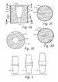
- FIGS. 2A–2Hdepict a schematic of the cross-section at various levels of the body of a prosthesis in accordance with the present invention
- FIG. 3illustrates joining members used with a prosthesis in accordance with the present invention
- FIG. 4depicts a centering guide for placement of a starting pin in accordance with the present invention
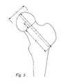
- FIG. 5illustrates how the center of rotation of the femoral head can be reproduced in accordance with the present invention
- FIG. 6depicts a prosthesis in accordance with the principles of the present invention
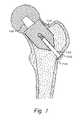
- FIG. 7illustrates a prosthesis in accordance with the principles of the present invention
- FIG. 8depicts a posterior view of a human femur having a femoral head and a femoral neck
- FIG. 9illustrates multiple cross-sectional views of the femoral head and femoral neck of FIG. 8 taken at A—A, B—B, and C—C;
- FIG. 10depicts a perspective view of a femoral neck clamp according to the principles of the present invention positioned at an isthmus of the femoral neck of FIG. 8 ;
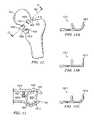
- FIG. 11illustrates a perspective view of the femoral neck clamp of FIG. 10 ;
- FIG. 12depicts a posterior view of a human femur with the femoral neck clamp of FIG. 10 shown installed at an isthmus of the femoral neck, the handle members of the femoral neck clamp being omitted for clarity;
- FIG. 13illustrates a cross-sectional distal view of the femur and femoral neck clamp of FIG. 12 taken at XIII—XIII;
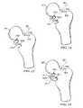
- FIG. 13A–13Cdepict alternative shapes of an inferior clamping member of the femoral neck clamp of FIG. 13 ;
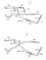
- FIG. 14illustrates a posterior view of the femur and femoral neck clamp having superior and inferior clamping members, the inferior clamping member having a proximal clasp attached to a distal clasp by a connecting member according to principles of the present invention
- FIG. 15depicts a posterior view of a femur and femoral neck clamp similar to those of FIG. 14 , the femoral neck clamp having an alternative connecting member according to the principles of the present invention
- FIG. 16illustrates a posterior view of a femur and femoral neck clamp similar to those of FIG. 14 , the femoral neck clamp having an alternative connecting member according to the principles of the present invention
- FIG. 17depicts a side view of a femoral neck clamp according to the principles of the present invention.
- FIG. 18illustrates a side view of a femoral neck clamp according to the principles of the present invention
- FIG. 19depicts a posterior view of a human femur having a femoral neck clamp attached to a femoral neck of the femur, a locator shaft connected to the femoral neck clamp, and a pin locator guide slidingly received on the locator shaft;
- FIG. 20illustrates a perspective view of a human femur having a cutting guide positioned on pins placed in the femoral head using the pin locator guide of FIG. 19 ;
- FIG. 20Adepicts a method of resecting a femoral head according to the principles of the present invention
- FIG. 21illustrates a perspective view of a starter guide according to the principles of the present invention and a human femur having the femoral head of the femur resected;
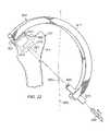
- FIG. 22depicts a posterior view of a human leg, including a human femur, and a drilling guide according to the principles of the present invention for preparing the femur for implantation of a femoral neck prosthesis;
- FIG. 23illustrates a side view of the drilling guide of FIG. 22 ;
- FIG. 23Adepicts a method of preparing a femur for implantation of a prosthesis according to the principles of the present invention
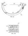
- FIG. 24illustrates a posterior view of a femoral neck liner and a reamer path protector according to the principles of the present invention, the femoral neck liner being positioned within a femoral neck, and the reamer path protector being threadingly received by the femoral neck liner;
- FIG. 25depicts a side view of the reamer path protector and femoral neck liner of FIG. 23 ;
- FIG. 25Aillustrates a method of preparing an acetabulum according to the principles of the present invention.
- FIG. 26depicts a method of implanting a prosthesis in a femur according to the principles of the present invention.
- the present inventionprovides a femoral neck fixation prosthesis and a method of implanting the prosthesis which reduces bone loss and avoids the other shortcomings of the prior art by allowing the fixation of a stable femoral head replacement while reducing the amount of the femur, that must be removed and reamed for the insertion of the prosthesis.
- the preferred embodimentprovides that the femoral head is attached to a fixation prosthesis, which extends coaxially through the central canal of the femoral neck, into the femur, and is then attached to the opposite lateral wall of the femur. In this manner, the prosthesis serves to imitate the original structure of the femoral head while substantially retaining the natural femoral neck. No other support members, either crosspins or arms extending into the length of the femur, are required.
- a femoral neck fixation prosthesis in accordance with the principles of the present inventionis designed to achieve fixation in the femoral neck with or without cement. Therefore, revision of the disclosed femoral neck fixation prosthesis would essentially become the complexity of a present day primary hip arthroplasty for the femoral component.
- the improved femoral neck fixation prosthesiswould require an operation equivalent to a primary arthroplasty on the femoral side. Therefore it would be ideal for the younger patient, but would also be recommended for the older patients with accommodating anatomy.
- the innovative method for implanting the femoral neck fixation prosthesiswould allow less muscular dissection, and the capsule can be repaired anteriorly at the end of the procedure.
- the disclosed femoral neck fixation prosthesisis designed to be used with larger diameter femoral heads. The combination of these factors would significantly improve stability of the hip. The goal is to minimize the need for hip position precautions postoperatively.
- One advantage of the preferred embodimentis that less bone would be resected initially using the femoral neck fixation prosthesis, and the stress would be transferred to the bone in the femoral neck. The metaphysis and the diaphysis of the proximal femur would be minimally disturbed. Only the femoral head itself will be resected.
- Another advantage of the preferred embodimentis that the femoral neck length and offset would be accurately measured and reproduced when using the femoral neck fixation prosthesis. Leg length inequality due to hip arthroplasty could be minimized, and muscle mechanics could be accurately restored.
- an operation using the femoral neck fixation prosthesiswould be less invasive with less blood loss, less post operative pain, and less perioperative morbidity than an operation that employs the vast majority of commonly used prostheses.
- the economic implications of a shorter hospital stay, fewer blood transfusions, and fewer medical complicationsare significant.
- FIG. 1A femoral neck fixation prosthesis according to the principles of the present invention is shown in FIG. 1 , wherein femur 100 is shown with femoral neck 105 , joining member 115 , and prosthetic head 110 .
- An uncemented porous coated femoral prosthesis body 125 with a modular head 110 and joining member 115is provided.
- the metal usedis preferably either titanium or chrome-cobalt based, and can be any metal commonly used in hip prosthesis construction. The modulus of elasticity of such a short segment will be of less significance than in a standard femoral stem.
- the coatingis preferably either sintered beads or plasma sprayed, depending on the type of metal used for the body of the prosthesis.
- the body 125 of the prosthesiswill preferably be available in various diameters, approximately every 1–1.5 mm.
- the length of the prosthesiswill preferably be chosen from one or two lengths, approximately 30 mm. Most of the fixation and ingrowth of the bone to the prosthesis will occur in the first 10–20 mm.
- fixation to the femurwill be achieved by reaming the femoral neck 105 to accommodate a cylindrical porous coated sleeve body 125 , which is supported by a proximal collar and given distal stability with a compression screw 120 through the lateral wall of the femur just distal to the greater tuberosity (location 140 ). Reaming will be progressive until the cortex of the femoral neck is encountered. A femoral component 1 ⁇ 2 mm greater than the last diameter reamed will then be selected.
- the long axis of the body of the component body 125will coincide with a longitudinal axis in the preoperative femur 100 corresponding to an imaginary line connecting the center of the femoral neck 105 with the center of the femoral head 110 .
- Resection of the femoral headwill be measured such that the center of rotation of the femoral head 110 can be measured and reproduced.
- the femoral neck 105will be reamed with a planar reamer that fits in the reamed canal of the femoral neck 105 to establish a flat surface.
- the proximal body 125 of the prosthesiswill have the female end of a morse taper to allow the attachment of the joining member 115 .
- a compression screw 120passes through the center of the body of the prosthesis. This screw attaches to a barrel nut 130 in the lateral wall of the femur at point 140 and preferably has a hexagonal head.
- the screw 120is preferably smooth in the segment within the body of the prosthesis and has threads on the distal end.
- the tunnel through the body of the prosthesisforms a snug fit around the smooth portion of the screw 120 .
- the barrel nut 130is preferably angled to be flush with the lateral side of the femur at point 140 .
- the head of the screw 120is preferably located in the base of the morse taper in the body 125 of the femoral component.
- This screw 120adds stability to the construct by giving antero-posterior and varus-valgus stability to the body 125 of the prosthesis and by compressing the prosthesis on the neck 105 of the femur 100 . These screws will be available in various lengths.
- this innovative designallows the prosthesis to be installed and used without requiring any other fastener on the femur.
- the preferred embodimentdoes not require any additional screws or other fasteners to be placed in the femur, and does not require any sort of support plate on the lateral wall of the femur.
- Male-male morse taper joining member 115acts as a joining portion in connecting the body 125 of the prosthesis to the femoral head 110 . Adjustments in joining member length will occur in this segment with several lengths of joining member segments available for each femoral body and femoral head. The joining member segment needed to exactly reproduce the center of rotation of the femoral head will be known based on the amount of bone resected.
- the joining member 115has male morse tapers 135 on each side, and will have a variable-length section in between the morse tapers to fit the specific patient.
- the femoral head 110will have a female morse taper to connect to the joining member 115 .
- Femoral heads 110will be of various diameters depending on the acetabulum, and several exemplary sizes are shown in FIG. 1 . Ideally, larger femoral head diameters (e.g., 36 mm to 50 mm) are used to both improve stability and prevent impingement of the neck on the acetabular rim.
- the femoral head 110is preferably polished chrome-cobalt, as the industry standard, but other materials can be used.
- a de-rotation componentis added to reduce the likelihood of the rotation of the prosthesis within the femoral neck. This can be accomplished with a pin or stem with grooves or slots that passes through the lateral cortex into the body of the prosthesis. This would then be compressed with a screw, which would be put through the head end of the body of the prosthesis into the stem.
- femoral neck fixation prostheses described hereincan be used with or without cement.
- FIGS. 2A–2Cshow several cross-sectional views of the cylindrical porous coated body 225 of the prosthesis of the preferred embodiment.
- FIG. 2Ashows a longitudinal cross-section of the body 225 .
- a collar 248 at the proximal end of the body 225is illustrated, as is the female morse taper cavity 246 , which is fit to receive the joining member.
- the collar 248is configured to abut the proximal end of the resected femoral neck.
- Communicating with cavity 246is tubular channel 247 which will receive the compression screw.
- Below the collar 248the exterior of the body 225 has a porous coated layer 249 .
- the body member 225can also be configured with a triangular ( FIG. 2E ), scalloped ( FIG. 2F ), oval ( FIG. 2H ), or fluted ( FIG. 2G ) cross-section.
- FIG. 2Bshows a lateral cross-section of body 225 as cut across line B of FIG. 2A .
- the cavity 246is shown, and the proximal collar 248 is also illustrated.
- FIG. 2Cshows a lateral cross-section of body 225 as cut across line C of FIG. 2A .
- channel 247 for the compression screwis shown passing through the center of body 225 .
- porous coated layer 249is shown on the exterior of body 225 .
- a cross-section across line D of FIG. 2Ais the same as described for line C of that FIG.
- FIG. 3shows joining members 316 / 317 / 318 of various sizes, which can be used for patients with differing requirements.
- Each joining member 316 / 317 / 318has a morse taper on each end, and a variable-length straight section connecting the morse tapers.
- FIG. 4depicts the centering guide for placement of the starting pin in accordance with the principles of the present invention.
- femoral neck gripping clamp 405is to grip and hold the femoral neck after the femoral head centering device 410 has been placed over the patient's femoral head.
- the femoral neck gripping clamp 405is expanded or contracted using adjustment piece 420 , which operates gears 415 .
- Cannulated rod 425which is connected to femoral head centering device 410 , allows pin insertion into the cannula at 435 .
- Free nut 430is used to tighten the femoral head centering device 410 .
- the centering guide shown in FIG. 4is preferably made of a stiff metal, and can also be used as a retractor to expose the femoral head.
- FIG. 5depicts how the center of rotation of the femoral head can be reproduced in accordance with a preferred embodiment of the present invention.
- distance Afrom the head to the lateral cortex is measured.
- distance Bfrom the cut surface to the lateral cortex is measured.
- the diameter D of the femoral headis also measured.
- Distance Cthen represents the distance from the cut surface of the femoral neck that the prosthetic femoral head center-of-rotation should be placed in order to reproduce the pre-operative femoral head center-of-rotation.
- compression screw 620is inserted through the lateral wall of the femur at location 640 and screwed into the body 625 of the femoral component. This simplifies the barrel nut portion of the design shown in FIG. 1 . It would require that the screw 620 be of various lengths that would engage the body 625 of the prosthesis without reaching the depth of the hole in the femoral prosthesis. The body of the prosthesis would preferably be longer, using optional extension 650 to provide enough length so that the compression screw will be stable within the body of the prosthesis.
- FIG. 6The remainder of FIG. 6 is similar to FIG. 1 .
- femur 600is shown with femoral neck 605 , joining member 615 , and prosthetic head 610 .
- This embodimentprovides an uncemented porous coated femoral prosthesis body 625 with a modular head 610 and joining member 615 .
- the body 625 of the prosthesisinclude threads 655 for receiving screw 620 .
- fixation to the femurwill be achieved by reaming the femoral neck 605 to accommodate a cylindrical porous coated sleeve body 625 , which is supported by a proximal collar and given distal stability with a compression screw 620 through the lateral wall of the femur just distal to the greater tuberosity (location 640 ).
- the long axis of the body of the component body 625will coincide with a longitudinal axis in the preoperative femur 600 corresponding to an imaginary line connecting the center of the femoral neck 605 with the center of the femoral head 610 .
- Resection of the femoral headwill be measured such that the center of rotation of the femoral head 610 can be measured and reproduced as discussed with reference to FIG. 5 .
- the femoral neck 605will be reamed with a flat reamer that fits in the reamed canal of the femoral neck 605 to establish a flat surface.
- the proximal body 625 of the prosthesiswill have the female end of a morse taper to allow the attachment of the femoral neck 615 .
- Compression screw 620passes through the center of the body of the prosthesis.
- the screw 620is preferably smooth in the segment within the body of the prosthesis and has threads on the proximal end, for engaging threads 655 .
- the tunnel through the body of the prosthesisforms a snug fit around the smooth portion of the screw 620 .
- Screw 620adds stability to the construct by giving antero-posterior and varus-valgus stability to the body 625 of the prosthesis and by compressing the prosthesis on the neck 605 of the femur 600 . These screws will be available in various lengths.
- Male-male morse taper joining member 615connects the body 625 of the prosthesis to the femoral head 610 . Adjustments in joining member neck length will occur in this segment with several lengths of joining member segments available for each femoral body and femoral head. The joining member segment needed to exactly reproduce the center of rotation of the femoral head will be known based on the amount of bone resected.
- the femoral head 610will have a female morse taper to connect to the joining member 615 .
- Femoral heads 610will be of various diameters depending on the acetabulum. Ideally larger femoral head diameters (e.g., 36 mm to 60 mm) are used to both improve stability and prevent impingement of the neck on the acetabular rim.
- the femoral head 610is preferably polished chrome-cobalt, as the industry standard, but other materials can be used.
- FIG. 7shows a preferred embodiment of the femoral neck fixation prosthesis of the present invention. If the compression screw 720 , with washer 745 , is inserted through the lateral wall of the femur at 740 , the length of the body 725 of the prosthesis may not be long enough to provide adequate stability for the compression screw 720 . In order to provide this stability for the compression screw, a fixed length joining member 760 on the body of the prosthesis would be necessary to act as a joining member, abandoning the modular joining member ( 115 in FIG. 1 ).
- the varied lengths required on the joining memberwould be incorporated into the femoral head either with separate individual lengths for each head diameter ( 2 to 3 for each diameter femoral head) or by using an interposing piece of metal to provide additional neck length. The latter is done with several femoral components available on the market today.
- the femoral neck fixation prosthesisis implanted by first preparing the femur for reception of the prosthesis.
- FIG. 8several orientations and anatomical features relative to a femur 811 should first be defined to more easily understand the process of preparing the femur and implanting the prosthesis.
- the term “medial”shall mean “pertaining to the middle,” while the term “lateral” shall mean “pertaining to the side.”
- the femur 811includes a medial side 813 and a lateral side 815 .
- proximalshall mean “nearest the point of attachment, center of the body, or point of reference,” while the term “distal” shall mean “the opposite of proximal, or farthest from the center, from a medial line, or from the trunk.”
- proximal and distalare generally used to convey positional or directional information relative to a particular feature, so it would not be entirely proper to refer to a proximal “side” of the femur or a distal “side” of the femur. However, these terms can be demonstrated by comparing some of the basic anatomy of the femur.
- Femur 811includes a femoral head 821 , a femoral neck 823 , a shaft 825 , a greater trochanter 827 , and a lesser trochanter 829 . Since the femoral head 811 serves as a point of attachment when it is received by the acetabulum (not shown), the femoral head 821 is located proximal to the femoral neck 823 and the shaft 825 . The shaft 825 is located distal to both the femoral neck 823 and the femoral head 821 .
- the term “superior”shall mean “higher than or situated above something else,” while the term “inferior” shall mean “beneath or lower.”
- the term “anterior”shall mean “before or in front of” and shall generally refer to the ventral or abdominal side of the body.
- the term “posterior”shall mean “toward the rear” and shall generally refer to the back or dorsal side of the body.
- a posterior side 831 of the femur 811is shown in FIG. 8 , while the anterior side is hidden from view in FIG. 8 .
- a longitudinal axis 845 of the femoral neckis difficult to precisely define because the geometry of the femoral neck 823 is usually not perfectly cylindrical.
- the femoral neck 823were sectioned along its length at a finite number of cross-sectional planes (e.g. B—B and C—C in FIG. 8 ), and the center of each cross-section were determined, the line passing through the center of rotation of the femoral head (described previously with reference to FIG. 5 ) and passing through an average of the centers of the cross-sections would likely represent the longitudinal axis 845 of the femoral neck 823 . In reality, it is difficult to locate the center of each cross-section of the femoral neck 823 .
- each cross-sectionis located at a plane perpendicular to the longitudinal axis 845 , but this presents a somewhat circular method for determining the orientation of the cross-sectional planes and the longitudinal axis 845 .
- the isthmus 849is the narrowest point on the femoral neck 823 when viewed from the anterior or posterior side of the femur 811 .
- Visualization of the posterior side 831 of the femur 811allows a lateral line to be constructed across the femoral neck 823 at the isthmus 849 .
- the line at section C—-Crepresents an isthmus plane 851 , which is a cross-sectional plane extending through the femur in an antero-posterior direction.
- This plane at the isthmus 849 of the femoral neck 823allows a close approximation of a plane that would be perpendicular to the longitudinal axis 845 of the femur 811 .
- Other cross-sectional planes visualized through the femoral neck 823would be parallel to the isthmus plane at the isthmus 849 .
- the femoral neck 823is not actually cut at each of the cross-sectional planes discussed above. Rather, the visualization of these planes is helpful in determining, theoretically, where the longitudinal axis 845 of the femoral neck 823 would lie. It would be sufficient to define the longitudinal axis 845 as the line passing through the center of rotation of the femoral head 821 and the center of the femoral neck 823 at the isthmus 849 .
- the longitudinal axis 845as the line passing through the center of rotation of the femoral head 821 and the average of the centers of the femoral neck 823 taken at several cross-sections, all of which are parallel to the isthmus plane 851 . It should also be noted that for some patients, the center of rotation of the femoral head may not necessarily coincide with the longitudinal axis 845 .
- the visualization of the “center” of the femoral neckis not necessarily simple due to the varying geometry of the femoral neck 823 .
- a cross-section taken at A—A in a region of transition between the femoral head 821 and the femoral neck 823is approximately round.
- the cross-sectional shapes of the femoral neck 823 taken at B—B and C—Care not perfectly round, and instead have various protrusions and other anatomical features that make it difficult to locate the center point of the cross-section.
- a cross-section from a more proximal portion of the femoral neck 823is illustrated at B—B and demonstrates that this portion of the neck is somewhat circular in shape.
- Cross-section C—C at the isthmus 849 of the femoral neck 823illustrates several prominent features that cause the femoral neck 823 to deviate from a perfectly round shape.
- the features of the femoral neck at C—Cinclude an antero-superior ridge 850 and a postero-inferior ridge 855 .
- the antero-superior ridge 850is a pronounced feature of the femoral neck 823 at this part of the femoral neck 823 and joins the greater trochanter 827 in a region distal to the isthmus 849 .
- the postero-inferior ridge 855is less pronounced and joins the lesser trochanter 829 in a region distal to the isthmus 849 .
- the femoral neck 823includes a relatively flat superior surface 857 , while an inferior surface 859 is more rounded.
- the center of any given cross-sectionwill be at the mean geometric center for any particular cross-section.
- the mean geometric centers of all the cross-sectionsmay not be aligned such that the centers can be connected by a line.
- a line representing longitudinal axis 845could be drawn through the center of rotation of the femoral head and through the plurality of cross-sectional centers so as to minimize deviation with respect to the plurality of cross-sectional centers. If the femoral head is misshapen, the longitudinal axis 845 may be considered only with respect to the cross-sectional centers and not the center of rotation of the femoral head.
- the center of each cross-sectioncould be located based on the shape of the cancellous bone at that cross-section. Since the prosthesis according to the principles of the present invention is to be implanted within the cancellous bone, it may be more appropriate to define the center of the femoral neck 823 based on the shape and location of the cancellous bone. The center of each cross-section would be the point at which a circle circumscribed around the point would most fully contact the surrounding cortex.
- the “location” and/or “visualization” of the longitudinal axis 845 of the femoral neck 823is theoretical and is discussed to more easily explain how the femoral neck fixation prosthesis is oriented and implanted within the femur 811 . It is not necessarily required that the longitudinal axis 845 be found prior to implanting the prosthesis; however, it is important to note that in most cases, the femoral neck fixation prosthesis will be installed in the femur such that a longitudinal axis of the prosthesis is substantially coaxial to the longitudinal axis 845 of the femoral neck 823 as described above.
- This implantationcould be accomplished by using non-invasive techniques such as X-rays or magnetic resonance imaging (MRI) to visualize and locate the longitudinal axis 845 of the femoral head 823 , but in most instances, the prosthesis will be implanted using specialized tools that properly orient the prosthesis based on anatomical landmarks on the femoral neck. We believe that the use of these tools and anatomical landmarks will closely align the prosthesis with the longitudinal axis of the femoral neck, thereby obviating the need for calculating or identifying the longitudinal axis during the procedure.
- non-invasive techniquessuch as X-rays or magnetic resonance imaging (MRI)
- Implantation of the femoral neck fixation prosthesisis accomplished by resecting the femoral head 821 , reaming at least one passage through the femoral neck, reaming the acetabulum, and implanting the femoral neck fixation prosthesis into the reamed passage.
- Access to the femoral head and femoral neckis accomplished by making a small incision in the gluteus maximus to expose the hip joint.
- the femoral head 821is dislocated from the acetabulum in a manner similar to that employed in current hip arthroplasty procedures.
- the leg of the patientis then internally rotated (i.e.
- the femoral headmay be resected as explained below from the internally rotated position.
- the remaining proceduresi.e. reaming the passages, reaming the acetabulum, and implanting the femoral neck fixation prosthesis
- the procedures for preparing the femur and implanting the prosthesiscould alternatively be accomplished by rotating the patient's leg externally if the location of the initial incision were moved.
- a femoral neck clamp 1011assists in locating the cutting plane at which the femoral head 821 is to be resected.
- the femoral neck clamp 1011does this by locating the isthmus 849 of the femoral neck 823 by grasping anatomical landmarks on the femoral neck, such as the antero-superior ridge 850 and the inferior region of the femoral neck 823 .
- the isthmus 849defines a line that is substantially perpendicular to the longitudinal axis 845 of the femoral neck 823 .
- the femoral neck clamp 1011includes an inferior clamping member 1013 and a superior clamping member 1015 .
- a locator shaft guide member 1021includes a cylindrical passage 1023 and is attached to either the inferior clamping member 1013 or the superior clamping member 1015 .
- the superior clamping member 1015preferably includes an arcuate region 1025 for securely gripping the antero-superior ridge 850 (see FIG. 9 ) of the femoral neck 823 ; however, the superior clamping member 1015 could be substantially flat with no arcuate region.
- the inferior clamping member 1013preferably includes a proximal clasp 1031 and a distal clasp 1033 that are connected by a connecting member 1035 .
- the inferior clamping member 1013cradles the inferior region of the femoral neck 823 with preferably at least two points of contact occurring between the femoral neck 823 and each of the proximal and distal clasps 1031 , 1033 .
- the shape of the proximal and distal clasps 1031 , 1033is V-shaped, the shape could be hemi-circular (see FIG. 13A ), square (see FIG. 13B ), polygonal (see FIG. 13C ), or any other shape that provides adequate contact with the femoral neck 823 .
- the inferior clamping member 1013may include only one clasp that is preferably aligned with the superior clamping member 1015 to locate the isthmus 849 of the femoral neck 823 .
- the femoral neck clamp 1011preferably includes a handle portion 1041 having a pair of handle members 1043 biased apart by a spring member 1045 .
- the spring member 1045is preferably made from sheets of spring steel and shaped to hold the handle members 1043 apart in an open position.
- the spring member 1045could be any device used to apply such a force, including without limitation a helical spring, a leaf spring, or a resilient bushing.
- a pair of rods 1047is rigidly attached to one of the handle members, and each rod 1047 passes through an aperture 1049 in the other handle member 1043 .
- the rods 1047assist in guiding the movement of the handle members 1043 relative to one another.
- a surgeoncan decrease the distance between the inferior and superior clamping members 1013 , 1015 in order to position the clamping members securely around the femoral neck.
- the spring member 1045pushes the handle members 1043 apart, thereby returning the femoral neck clamp 1011 to the open position.
- the configuration of the handle members 1043 , rods 1047 , and spring member 1045allow the inferior and superior clamping members 1013 , 1015 to move in translational, parallel fashion relative to one another when the handle members 1043 are squeezed. Since rotation of the handle members 1043 relative to one another is avoided, the inferior and superior clamping members 1013 , 1015 are allowed to more effectively grip the appropriate anatomical features of the femoral neck 823 .
- a locking member 1051may be attached to the handle portion 1041 to lock the inferior and superior clamping members 1013 , 1015 once positioned around the femoral neck 823 .
- the locking member 1051 shown in FIG. 11is pivotally attached to one of the handle members 1043 and is rotatably positionable to engage a plurality of teeth 1053 on at least one of the rods 1047 . In FIG. 11 , two locking members 1051 are shown.
- the femoral neck clamp 1011is used to locate the isthmus plane 851 , which is represented by a line in FIG. 12 at the isthmus 849 of the femoral neck 823 .
- the inferior and superior clamping members 1013 , 1015are first positioned on inferior and superior sides of the femoral neck 823 , respectively, with the superior clamping member 1015 and the proximal clasp 1031 visually aligned with an area of the femoral neck 823 that appears to be the isthmus 849 .
- the handle members 1043are squeezed, the superior clamping member 1015 and the proximal clasp 1031 grip the femoral neck 823 in the area of the isthmus 849 .
- Preventing rotation of the femoral neck clamp 1011 about the line representing isthmus plane 851 in FIG. 12could also be accomplished by having an inferior clamping member 1013 that included a single clasp with a wider area of contact on the inferior region of the femoral neck 823 .
- widening either the inferior clamping member 1013 or the superior clamping member 1015 too muchwill decrease the ability of the femoral neck clamp 1011 to find the isthmus 849 since the inferior and superior clamping members 1013 , 1015 will be unable to properly settle into the concave portions of the femoral neck 823 as illustrated in FIG. 12 .
- Both the inferior and superior clamping members 1013 , 1015take advantage of anatomical landmarks present on the femoral neck 823 to locate the isthmus 849 and the isthmus plane 851 , which is typically substantially perpendicular to the longitudinal axis 845 of the femoral neck 823 .
- the superior clamping member 1015primarily contacts and, depending on whether it includes an arcuate region 1025 , cradles the antero-superior ridge 850 (see FIG. 13 ).
- the inferior clamping member 1013including the proximal and distal clasps 1031 , 1033 , preferably is formed in one of the shapes previously described (see FIGS.
- the distal clasp 1033 of the inferior clamping member 1013provides stability to the femoral neck clamp 1011 to prevent rotation of the femoral neck clamp 1011 about the line representing isthmus plane 851 in FIG. 12 .
- the distal clasp 1033is preferably not directly connected to either handle member 1043 , but rather is connected to proximal clasp 1031 by the connecting member 1035 , which allows rotation of the distal clasp 1033 relative to the proximal clasp 1031 .
- the application of force through the handle members 1043is directed primarily to the superior clamping member 1015 and the proximal clasp 1031 .
- FIGS. 14–16 in the drawingsseveral different variations of the connecting member 1035 are shown, each of which would be suitable to allow rotation of the distal clasp 1033 .
- a connecting member 1411is rigidly connected to the distal clasp 1033 and pivotally connected to the proximal clasp 1031 .
- a torsion spring(not shown) is operably connected to the proximal clasp 1031 and the connecting member 1411 to bias the distal clasp 1033 toward the femoral neck 823 in a counter-clockwise direction (with respect to the view shown in FIG. 14 ).
- a connecting member 1511is rigidly connected to both the proximal and distal clasps 1031 , 1033 .
- the connecting member 1511is preferably made from a resilient material such as spring steel that allows rotation of the distal clasp 1033 relative to the proximal clasp 1031 , but provides sufficient force to the distal clasp 1033 to firmly contact the femoral neck 823 .
- a connecting member 1611is rigidly attached to the distal clasp 1033 and is pivotally attached to the proximal clasp 1031 .
- the connecting memberincludes a slot 1615 ; and a fastener 1617 , preferably a screw, a bolt, or a locking pin, is received through the slot 1615 and is attached to the proximal clasp 1031 .
- the fastener 1617allows rotation of the distal clasp 1033 to be selectively chosen. After rotating the distal clasp 1033 enough to firmly contact the femoral neck 823 , the fastener can be tightened or locked in place to prevent further rotation of the distal clasp 1033 relative to the proximal clasp 1031 .
- the locator shaft guide member 1021 of the femoral neck clamp 1011is connected to the superior clamping member 1015 or the handle member 1043 adjacent the superior clamping member 1015 .
- the locator shaft guide member 1021is oriented such that the cylindrical passage 1023 of the locator shaft guide member 1021 is substantially parallel to the longitudinal axis 845 of the femoral neck 823 when the femoral neck clamp 1011 is finally positioned at the isthmus 849 .
- the locator shaft guide member 1021will be rigidly connected to the superior clamping member 1015 because the anatomy of most femurs is such that the positioning of femoral neck clamp 1011 at the isthmus 849 will provide automatic, parallel alignment of the locator shaft guide member 1021 relative to the longitudinal axis 845 of the femoral neck 823 .
- the locator shaft guide member 1021may be adjustably mounted to the superior clamping member 1015 to allow for rotational adjustment and visual alignment of the locator shaft guide member 1021 relative to the longitudinal axis 845 .
- a femoral neck clamp 1711according to the principles of the present invention includes an inferior clamping member 1713 and a superior clamping member 1715 similar to those of femoral neck clamp 1011 .
- Femoral neck clamp 1711includes a parallelogram, four-bar-linkage mechanism 1721 to provide translational movement (as opposed to rotational movement) of the inferior clamping member 1713 relative to the superior clamping member 1715 .
- Linkage mechanism 1721includes an inferior handle member 1743 pivotally connected to a superior handle member 1745 .
- Superior handle member 1745is pivotally connected at one end to a coupler link 1747 that is rigidly connected to the superior clamping member 1715 .
- a side link 1751is pivotally connected at one end to the coupler link 1747 and at another end to the inferior handle member 1743 .
- the side link 1751 and the portion of the superior handle member 1745 extending between the inferior handle member 1743 and the coupler link 1747are preferably parallel and equal in length.
- the coupler link 1747 and the portion of the inferior handle member 1743 extending between the superior handle member 1745 and the side link 1751are preferably parallel and equal in length.
- a torsion spring 1753may be operably connected to the inferior handle member 1743 and superior handle member 1745 to bias the handle members 1743 , 1745 , and thus the inferior and superior clamping members 1713 , 1715 , apart.
- a locking member 1755may be pivotally attached to an end of either the inferior or superior handle members 1743 , 1745 .
- the locking member 1755includes a plurality of teeth 1759 adapted to engage the other handle member 1743 , 1745 and thus lock the inferior clamping member 1713 relative to the superior clamping member 1715 .
- a locator shaft guide member 1765is connected to either the inferior clamping member 1713 or the superior clamping member 1715 similar to locator shaft guide member 1021 of FIG. 12 .
- the locator shaft guide member 1765could be connected to coupler link 1747 , inferior handle member 1743 , or superior handle member 1745 near the inferior and superior clamping members 1713 , 1715 .
- a femoral neck clamp 1811according to the principles of the present invention includes an inferior clamping member 1813 and a superior clamping member 1815 similar to those of femoral neck clamp 1011 .
- Femoral neck clamp 1811further includes an inferior handle member 1843 pivotally connected to a superior handle member 1845 .
- a torsion spring 1853may be operably connected to the inferior handle member 1843 and superior handle member 1845 to bias the handle members 1843 , 1845 , and thus the inferior and superior clamping members 1813 , 1815 , apart.
- a locking member 1855may be pivotally attached to an end of either the inferior or superior handle members 1843 , 1845 .
- the locking member 1855includes a plurality of teeth 1859 adapted to engage the other handle member 1843 , 1845 and thus lock the inferior clamping member 1813 relative to the superior clamping member 1815 .
- a locator shaft guide member 1865is connected to either the inferior clamping member 1813 or the superior clamping member 1815 similar to locator shaft guide member 1013 of FIG. 12 .
- the femoral neck clamp 1011(could also be femoral neck clamp 1711 or 1811 ) has been positioned around the femoral neck 823 at the isthmus 849 such that the superior clamping member 1015 and the proximal clasp 1031 of the inferior clamping member 1013 are aligned with the isthmus plane 851 .
- the distal clasp 1033also engages the femoral neck 823 to prevent rotation of the femoral neck clamp 1011 about the line representing isthmus plane 851 .
- the locator shaft guide member 1021is automatically aligned such that a longitudinal axis of the cylindrical passage 1023 of the locator shaft guide member 1021 is oriented at an angle of approximately ninety (90) degrees to the isthmus plane 851 .
- a locator shaft 1911is positioned within the cylindrical passage 1023 of the locator shaft guide member 1021 after the femoral neck clamp 1011 has been positioned at the isthmus 849 of the femoral neck 823 .
- a base plate 1915is rigidly connected to an end of the locator shaft 1911 such that following insertion of the locator shaft 1911 in the cylindrical passage 1023 , the locator shaft 1911 can be advanced in a distal/lateral direction until the base plate 1915 abuts the femoral head 821 .
- Indicia 1921 in the form of ruled demarcationsis printed along the locator shaft 1911 for accurately positioning a pin locator guide 1925 , which is slidingly received on the locator shaft 1911 .
- Pin locator guide 1925preferably includes at least two spaced apart holes 1931 that may be located on one side of the locator shaft 1911 , or as illustrated in FIG. 19 , may be located on opposite sides of the locator shaft 1911 . Holes 1931 are positioned on the pin locator guide 1925 such that a line connecting the center of the holes 1931 is preferably parallel to the isthmus plane 851 .
- a cutting guide 2021includes a pair of holes 2027 that are spaced apart the same distance as the holes on the pin locator guide 1925 . The cutting guide 2021 is placed over the pins 2011 such that the pins 2011 are received by the holes 2027 .
- a cutting slot 2025is positioned on the cutting guide 2021 such that it is oriented substantially parallel to a line connecting the centers of the two holes 2027 .
- the cutting guide 2021places the cutting slot 2025 a known distance from the pins 2011 to allow resection of the femoral head 821 along a cutting plane (not shown) that is substantially parallel to the isthmus plane 851 .
- the femoral head 821is resected from the femur 811 by inserting a cutting blade or other cutting tool through the cutting slot 2025 and cutting through that portion of the femur 811 .
- the locator shaft 1911includes indicia 1921 in the form of ruled demarcations that are spaced apart precise distances. These demarcations can be used to precisely locate the cutting plane relative to the proximal end of the femoral head 821 .
- the amount of resection that will be performeddepends on several factors.
- a prosthetic femoral headwill be chosen to match the measured diameter of the patient's native femoral head. This is done to insure that the center of rotation is closely matched by the prosthesis and that the length of the patient's leg is not significantly lengthened or shortened. Based on the diameter chosen for the prosthetic femoral head, a height of the prosthetic femoral head (measured along longitudinal axis 845 ) will be known.
- This heightequates to the amount of bone resected from the proximal end of the native femoral head 823 . Since the distance between the holes 2027 on the cutting guide 2021 and the cutting slot 2025 is known, the pin locator guide 1925 can be accurately positioned along the locator shaft 1911 using the indicia 1921 to place the pin locator guide 1925 according to the amount of bone that needs to be resected. The placement of the pins 2011 using the pin locator guide 1925 then allows the cutting slot 2025 to be accurately positioned at the correct location to remove the correct length of bone.
- the cutting guide 2021 of the present inventioncould be combined with the femoral neck clamp 1011 to eliminate the need for a locator shaft 1911 and a pin locator guide 1925 .
- the combination clamp and cutting guidewould allow the clamp to be positioned at the isthmus 849 of the femoral neck 823 as previously described, but would provide a slot or other guide to allow resection of the femoral head along a cutting plane substantially parallel to the isthmus plane 851 .
- the slot or guidewould be adjustable relative to the isthmus plane 851 to allow a measured amount of bone to be resected from the femur 811 .
- a cutting guide that aligns the cutting plane a measured distance from the isthmus plane 851would be particularly useful in the event that the femoral head is missing, deformed, substantially misshapen, or broken. Measurements could be performed preoperatively using radiographic measurement techniques (e.g. X-ray).
- radiographic measurement techniquese.g. X-ray
- the first step at 2055includes positioning a locator shaft adjacent an exterior surface of the femoral head and substantially parallel to a longitudinal axis of the femoral neck.
- a pin locator guide having a least two holesis positioned along the locator shaft.
- a pinis inserted through each of the two holes in the pin locator guide and into the femoral head.
- the femoral headis resected by aligning a cutting guide relative to the pins at step 2065 .
- a proximal neck surface 2111is exposed that is substantially parallel to the isthmus plane 851 .
- Progressive reaming and drilling of the femoral neck 823is needed to prepare passages between the proximal neck surface 2111 and the lateral side 815 of the femur 821 .
- a starter guide 2121having a positioning portion 2125 and a guide portion 2127 is placed against the proximal neck surface 2111 such that the surface of the positioning portion 2125 opposite the guide portion 2127 mates with the proximal neck surface 2111 .
- the starter guide 2121further includes a guide passage 2131 that passes through both the guide portion 2127 and the positioning portion 2125 such that a longitudinal axis of the guide passage 2131 is substantially perpendicular to the proximal neck surface 2111 when the starter guide 2121 is placed against the proximal neck surface 2111 .
- a starter passage, or main passage, or primary passage 2141(represented in FIG. 21 by dashed lines) is formed in the femoral neck 823 from the proximal neck surface 2111 by first drilling a small hole 2145 using a drill bit or other boring tool placed in the guide passage 2131 .
- the starter passageis preferably drilled only partially into the femoral neck, and not through the lateral side 815 of the femur. When placing the starter guide 2121 and drilling the hole 2145 , it is preferred to visualize the approximate center of the femoral neck on the proximal neck surface 2111 so that the hole 2145 is approximately centered within the femoral neck 823 .
- the starter guide 2121is removed from the proximal neck surface 2111 , and the femoral neck 823 is progressively reamed until the hole 2145 extends to the cortical bone of the femoral neck 823 , thereby forming the starter passage 2141 .
- the starter passage 2141may only be possible to form the starter passage 2141 to contact the cortical bone at two points of contact. It is of course preferable to maximize the number of contacts of the cortical bone, and in most instances, it will be possible to contact the cortical bone in at least three locations without significantly decreasing the wall thickness of the cortex in any location.
- the starter passage 2141is reamed to a depth that is preferably equal to the longitudinal length of the body 125 , 625 , 725 (see FIGS. 1 , 6 and 7 ) of the femoral neck prosthesis.
- the final diameter of the starter passage 2141which is determined by how much reaming is needed to contact the cortical bone, will be slightly less than the chosen diameter of the body 125 , 625 , 725 of the prosthesis.
- a guidemay be placed flush against the proximal neck surface 2111 to orient a reamer at a ninety (90) degree angle to the proximal neck surface 2111 and center the reamer relative to the longitudinal axis of the femoral neck. The neck is sequentially reamed until the starter passage 2141 extends to the cortex.
- a guide pinmay be inserted into the femoral neck substantially parallel to the longitudinal axis of the femoral neck. The pin may be placed based on visualization or guided into place with a guide that is fixed relative to the femoral neck. The guide pin would be used to direct sequential reaming of the starter passage 2141 .
- a drilling guide 2211having an anchor member 2215 rigidly connected by a connecting member 2217 to an alignment sleeve 2219 is used to drill a distal passage, or fastener passage, or secondary passage 2221 (represented in FIG. 22 by dashed lines) from the lateral side 815 of the femur 811 .
- the alignment sleeve 2219includes an alignment passage 2225 for receiving a drill bit or other boring tool.
- the connecting member 2217may be C-shaped and connects the anchor member 2215 to the alignment sleeve 2219 such that a longitudinal axis of the alignment passage 2225 is coaxial to the longitudinal axis of the anchor member 2215 , both of which are coaxial to a longitudinal axis 2227 of the drilling guide 2211 .
- the anchor member 2215is cylindrical and sized to fit within the starter passage 2141 .
- the anchor member 2215could be interchangeable to allow different diameters to be used to properly fit within the starter passage 2141 of a particular patient.
- the anchor member 2215could be tapered to allow a snug fit within starter passages 2141 of several different diameters.
- the anchor member 2215may also include a collar 2231 for further stabilizing the drilling guide 2211 against the proximal neck surface 2111 when inserted into the starter passage 2141 .
- the alignment sleeve 2219is located on the lateral side 815 of the femur 811 .
- the patient's skin and other soft tissue 2233are located between the alignment sleeve 2219 and the femur 821 .
- the leg of the patientis then rotated to a neutral position, and an incision 2235 is made through the soft tissue of the patient in the vicinity of the alignment sleeve 2219 .
- a drilling bit 2241 or other boring toolis inserted through the alignment passage 2225 of the alignment sleeve 2219 for drilling the distal passage 2221 to join the starter passage 2141 .
- the distal passage 2221is easily formed coaxial to the starter passage 2221 . As shown in FIG. 22 , the distal passage 2221 is typically smaller in diameter than the starter passage 2141 , since the distal passage 2221 will receive the fastener 120 , 620 , 720 (see FIGS. 1 , 6 , and 7 ) for securing to the body 126 , 625 , 725 of the femoral neck fixation prosthesis.
- the primary reason for using a drilling guide 2211 to complete drilling through the femuris that it is less desirable to drill a hole completely through the femur from the proximal neck surface 2111 toward the lateral side 815 of the femur 811 .
- the patient's legWhen drilling from the proximal neck surface 2111 , the patient's leg would be in the internally rotated position. It is not as safe to drill through the lateral side 815 of the femur 811 when the leg is internally rotated because the drill bit may contact and sever vital anatomy, such as the femoral artery or other vessels and nerves, upon exiting the femur 811 . Since use of the drilling guide 2211 allows the leg to be rotated back to the neutral position, drilling can proceed from the lateral side 815 of the femur 811 without fear of contacting vital anatomy.
- a method of preparing a femur for implantation of a femoral neck fixation prosthesis 2321includes two steps.
- the first step at 2325includes first forming a main passage in the femoral neck from a medial side of the femur substantially coaxial to a longitudinal axis of a femoral neck.
- the second step at 2329includes second forming a secondary passage from a lateral side of the femur that is coaxial to and joins the main passage.
- the preparation of the femur for implantation of the prosthesisincludes forming two separate passages from different sides of the femur, the starter and distal passages could be formed from the same side of the femur.
- a guidemay be placed within the starter passage 2141 to guide drilling of the distal passage 2221 from the proximal side of the femoral neck 823 . Since the leg of the patient would likely be in an internally rotated position during this drilling procedure, care would be taken to only slightly penetrate the cortex on the lateral side of the femur 821 . This would help avoid major arteries and nerves in the patient's leg.
- the drilling guide 2211could be used to place the fastener 120 , 620 , 720 in the femur during the implantation of the femoral neck prosthesis, which is described in more detail below.
- the femur 811After forming both the starter passage 2141 and the distal passage 2221 , the femur 811 is capable of receiving the femoral neck fixation prosthesis. However, prior to implantation of the prosthesis, it may be desirable to prepare the acetabulum for receipt of an acetabular component (not shown) that will mate with the head of the femoral neck fixation prosthesis.
- the starter and distal passages 2141 , 2221may be used to guide the preparation of the acetabulum, which initially involves reaming.
- a reamer path protector 2411includes an insertion end 2415 and a handle end 2419 .
- the insertion endpreferably includes a plurality of threads 2421
- the handle end 2419includes a hand guard 2425 .
- a passage 2427passes through the reamer path protector 2411 .
- a femoral neck liner 2431is also provided and includes a main body 2435 having a passage 2437 and a collar 2439 .
- the passage 2437includes internal threads 2441 at an end of the main body 2335 opposite collar 2339 .
- the reamer path protector 2411is inserted from the lateral side 815 of the femur 811 and into the distal passage 2221 .
- the femoral neck liner 2431is inserted from the proximal neck surface 2111 into the starter passage 2141 until the collar 2439 mates with the proximal neck surface 2111 .
- the femoral neck liner 2431is sized in diameter the same as or slightly less than the diameter of the starter passage 2141 .
- the femoral neck liner 2431could be provided in different sizes to fit variously sized starter passages 2141 , or the femoral neck liner 2431 could be tapered.
- the reamer path protector 2411After inserting the femoral neck liner 2431 , the reamer path protector 2411 is advanced further into the distal passage 2221 until it contacts the femoral neck liner 2431 . The reamer path protector 2411 is then rotated to engage the threads 2421 with internal threads 2441 .
- the attachment mechanism between the reamer path protector 2411 and the femoral neck liner 2431is not required to be accomplished by a threaded connection.
- the connectioncould be formed by any mechanism that would allow the components to be easily disassembled following reaming of the acetabulum.
- reamer path protector 2411When the reamer path protector 2411 is securely fastened to the femoral neck liner 2431 , a sufficient portion of the reamer path protector 2411 remains extending outside of the femur 811 to allow gripping by the surgeon or other person who will ream the acetabulum. The reamer path protector 2411 is therefore gripped in this area, and a reamer shaft 2451 is inserted through the passage 2427 and the passage 2437 to connect to a reamer head 2453 near the proximal neck surface 2111 .
- the acetabulumis then reamed by rotating the patient's leg into a neutral position and applying power to rotate the reamer shaft 2451 and reamer head 2453 from the lateral side 815 of the femur 811 .
- Some internal rotation of the femur 811may also be necessary depending on the position of the femur 811 relative to flexion/extension and abduction/adduction.
- the acetabulumis progressively reamed until enough material has been removed to accommodate the acetabular component of the prosthesis. By reaming the acetabulum through the distal and starter passages 2221 , 2141 formed in the femur 811 , a highly effective reaming process is accomplished.
- the acetabulumcan be efficiently reamed to closely match the shape of the head of the prosthesis.
- the reamer head 2453is removed from the reamer shaft 2451 , and the reamer shaft 2451 is removed from the femoral neck liner 2431 and the reamer path protector 2411 .
- An impactor shaft(not shown) may be inserted into the reamer path protector 2411 and the femoral neck liner 2431 similar to the original insertion of the reamer shaft 2451 .
- the impactor shaftis releasably connected to an impactor head (not shown) near the proximal neck surface 2111 .
- the impactor shaft and impactor headare used to apply force to and seat the acetabular component of the prosthesis in the reamed acetabulum. After the acetabular component is firmly seated, the impactor shaft, impactor head, femoral neck liner 2431 , and the reamer path protector 2411 are disassembled and removed from the femur 811
- a first step 2525includes forming a primary passage within the femur substantially coaxial to a longitudinal axis of the femoral neck.
- a secondary passageis formed from a lateral side of the femur that joins and is coaxial to the primary passage.
- Step 2531includes inserting a reamer path protector having a reamer passage within the secondary passage.
- a reamer shaftis inserted through the reamer passage at step 2535 .
- a reamer headis attached to the reamer shaft at step 2539 , and the acetabulum is reamed at step 2541 .
- the femoral neck fixation prosthesisis implanted into the femur 811 by inserting the body 125 , 625 , 725 of the prosthesis into the starter passage 2141 .
- the diameter of the body 125 , 625 , 725is sized slightly larger than the diameter of the starter passage 2141 such that a secure fit within the starter passage 2141 is obtained when the body 125 , 625 , 725 is driven into the starter passage 2141 .
- the starter passage 2141is deep enough to accommodate the body 125 , 625 , 725 of the prosthesis and allow the collar of the body 125 , 625 , 725 to mate with the proximal neck surface 2111 .
- the fastener 120 , 620 , 720is then inserted into the distal passage 2221 from the lateral side 815 of the femur 811 .
- a small diameter pincan be used to locate and mark the passage when the leg is in the neutral position.
- the fastener 120 , 620 , 720which may be canullated (i.e. having a passage down the center of the shaft), can then be placed onto the pin and fed into the distal passage 2221 .
- the fastener 120 , 620 , 720is advanced into the distal passage 2221 until it contacts the body 125 , 625 , 725 of the prosthesis, at which time the fastener 120 , 620 , 720 is threadingly connected to the body 125 , 625 , 725 to secure the body within the femur 811 .
- the head 110 , 610 , 710 of the prosthesisis then installed on the morse taper 115 , 615 , 760 of the prosthesis be impacting the head of the prosthesis.
- a method of implanting a prosthesis in a femur 2611is illustrated.
- a main passageis formed in the femoral neck from a medial side of the femur substantially coaxial to a longitudinal axis of the femoral neck.
- a fastener passageis formed from a lateral side of the femur that is coaxial to and joins the main passage.
- Step 2623includes providing a femoral neck prosthesis having a body member connected to a head member.
- a portion of the body memberis inserted in the main passage.
- a fasteneris inserted into the fastener passage at step 2633 .
- the fasteneris connected to the body member to secure the femoral neck prosthesis within the femur.
Landscapes
- Health & Medical Sciences (AREA)
- Orthopedic Medicine & Surgery (AREA)
- Life Sciences & Earth Sciences (AREA)
- Transplantation (AREA)
- Engineering & Computer Science (AREA)
- Veterinary Medicine (AREA)
- Public Health (AREA)
- General Health & Medical Sciences (AREA)
- Animal Behavior & Ethology (AREA)
- Oral & Maxillofacial Surgery (AREA)
- Heart & Thoracic Surgery (AREA)
- Biomedical Technology (AREA)
- Vascular Medicine (AREA)
- Cardiology (AREA)
- Surgery (AREA)
- Nuclear Medicine, Radiotherapy & Molecular Imaging (AREA)
- Physical Education & Sports Medicine (AREA)
- Biophysics (AREA)
- Dentistry (AREA)
- Medical Informatics (AREA)
- Molecular Biology (AREA)
- Prostheses (AREA)
- Surgical Instruments (AREA)
Abstract
Description
C=(A−D/2)−B
Claims (4)
Priority Applications (3)
| Application Number | Priority Date | Filing Date | Title |
|---|---|---|---|
| US10/914,750US7104995B2 (en) | 2002-04-11 | 2004-08-09 | Method of preparing an acetabulum for receiving a head of a femoral prosthesis |
| PCT/US2005/028300WO2006020655A1 (en) | 2002-04-11 | 2005-08-09 | Method of implanting a femoral neck fixation prosthesis |
| US11/519,209US7695474B2 (en) | 2002-04-11 | 2006-09-11 | Method of preparing an acetabulum for receiving a head of a femoral prosthesis |
Applications Claiming Priority (6)
| Application Number | Priority Date | Filing Date | Title |
|---|---|---|---|
| US37183702P | 2002-04-11 | 2002-04-11 | |
| US10/228,907US6695883B2 (en) | 2002-04-11 | 2002-08-27 | Femoral neck fixation prosthesis |
| US10/779,353US20040162621A1 (en) | 2002-04-11 | 2004-02-14 | Femoral neck fixation prosthesis |
| US10/914,749US20050049714A1 (en) | 2002-04-11 | 2004-08-09 | Method of resecting a femoral head for implantation of a femoral neck fixation prosthesis |
| US10/914,748US20050010232A1 (en) | 2002-04-11 | 2004-08-09 | Method of implanting a femoral neck fixation prosthesis |
| US10/914,750US7104995B2 (en) | 2002-04-11 | 2004-08-09 | Method of preparing an acetabulum for receiving a head of a femoral prosthesis |
Related Parent Applications (1)
| Application Number | Title | Priority Date | Filing Date |
|---|---|---|---|
| US10/779,353Continuation-In-PartUS20040162621A1 (en) | 2002-04-11 | 2004-02-14 | Femoral neck fixation prosthesis |
Related Child Applications (1)
| Application Number | Title | Priority Date | Filing Date |
|---|---|---|---|
| US11/519,209ContinuationUS7695474B2 (en) | 2002-04-11 | 2006-09-11 | Method of preparing an acetabulum for receiving a head of a femoral prosthesis |
Publications (2)
| Publication Number | Publication Date |
|---|---|
| US20050010230A1 US20050010230A1 (en) | 2005-01-13 |
| US7104995B2true US7104995B2 (en) | 2006-09-12 |
Family
ID=28794142
Family Applications (8)
| Application Number | Title | Priority Date | Filing Date |
|---|---|---|---|
| US10/228,907Expired - Fee RelatedUS6695883B2 (en) | 2002-04-11 | 2002-08-27 | Femoral neck fixation prosthesis |
| US10/779,353AbandonedUS20040162621A1 (en) | 2002-04-11 | 2004-02-14 | Femoral neck fixation prosthesis |
| US10/914,748AbandonedUS20050010232A1 (en) | 2002-04-11 | 2004-08-09 | Method of implanting a femoral neck fixation prosthesis |
| US10/914,749AbandonedUS20050049714A1 (en) | 2002-04-11 | 2004-08-09 | Method of resecting a femoral head for implantation of a femoral neck fixation prosthesis |
| US10/914,750Expired - Fee RelatedUS7104995B2 (en) | 2002-04-11 | 2004-08-09 | Method of preparing an acetabulum for receiving a head of a femoral prosthesis |
| US11/519,209Expired - Fee RelatedUS7695474B2 (en) | 2002-04-11 | 2006-09-11 | Method of preparing an acetabulum for receiving a head of a femoral prosthesis |
| US12/069,693AbandonedUS20080208200A1 (en) | 2002-04-11 | 2008-02-12 | Drilling guide for use in implanting a femoral neck fixation prosthesis |
| US12/609,465AbandonedUS20100114101A1 (en) | 2002-04-11 | 2009-10-30 | Method of resecting a femoral head for implantation of a femoral neck fixation prosthesis |
Family Applications Before (4)
| Application Number | Title | Priority Date | Filing Date |
|---|---|---|---|
| US10/228,907Expired - Fee RelatedUS6695883B2 (en) | 2002-04-11 | 2002-08-27 | Femoral neck fixation prosthesis |
| US10/779,353AbandonedUS20040162621A1 (en) | 2002-04-11 | 2004-02-14 | Femoral neck fixation prosthesis |
| US10/914,748AbandonedUS20050010232A1 (en) | 2002-04-11 | 2004-08-09 | Method of implanting a femoral neck fixation prosthesis |
| US10/914,749AbandonedUS20050049714A1 (en) | 2002-04-11 | 2004-08-09 | Method of resecting a femoral head for implantation of a femoral neck fixation prosthesis |
Family Applications After (3)
| Application Number | Title | Priority Date | Filing Date |
|---|---|---|---|
| US11/519,209Expired - Fee RelatedUS7695474B2 (en) | 2002-04-11 | 2006-09-11 | Method of preparing an acetabulum for receiving a head of a femoral prosthesis |
| US12/069,693AbandonedUS20080208200A1 (en) | 2002-04-11 | 2008-02-12 | Drilling guide for use in implanting a femoral neck fixation prosthesis |
| US12/609,465AbandonedUS20100114101A1 (en) | 2002-04-11 | 2009-10-30 | Method of resecting a femoral head for implantation of a femoral neck fixation prosthesis |
Country Status (7)
| Country | Link |
|---|---|
| US (8) | US6695883B2 (en) |
| EP (1) | EP1499268B1 (en) |
| AT (1) | ATE465695T1 (en) |
| AU (1) | AU2003224886B2 (en) |
| CA (1) | CA2522033A1 (en) |
| DE (1) | DE60332338D1 (en) |
| WO (2) | WO2003086242A1 (en) |
Cited By (33)
| Publication number | Priority date | Publication date | Assignee | Title |
|---|---|---|---|---|
| US20050010232A1 (en)* | 2002-04-11 | 2005-01-13 | Crofford Theodre W. | Method of implanting a femoral neck fixation prosthesis |
| US20050197712A1 (en)* | 2004-03-08 | 2005-09-08 | Bigsby Robert John A. | Prosthesis |
| US20070043367A1 (en)* | 2005-07-25 | 2007-02-22 | Steven Lawrie | Orthopaedic appliances |
| US20080021475A1 (en)* | 2006-07-24 | 2008-01-24 | Steven Alan Lawrie | Orthopaedic appliances |
| US20080077144A1 (en)* | 2006-09-13 | 2008-03-27 | Crofford Theodore W | Self-opening skin staple |
| US20080312749A1 (en)* | 2007-06-15 | 2008-12-18 | Zimmer, Inc. | Single entry portal implant |
| US20090088863A1 (en)* | 2007-07-03 | 2009-04-02 | Benoist Girard Sas | Femoral prosthesis |
| US7641699B2 (en) | 2007-06-15 | 2010-01-05 | Unger Anthony S | Femoral head calcar loading prosthesis |
| US20100023131A1 (en)* | 2008-07-24 | 2010-01-28 | Howmedica Osteonics Corp. | Femoral head prosthesis |
| RU2405481C2 (en)* | 2009-02-18 | 2010-12-10 | Анатолий Львович Матвеев | Device for operational prevention of fractures of femoral proximal part resulting from osteoporosis by endoprosthetics of hip joint |
| US8029573B2 (en) | 2006-12-07 | 2011-10-04 | Ihip Surgical, Llc | Method and apparatus for total hip replacement |
| US20130204390A1 (en)* | 2006-12-07 | 2013-08-08 | Ihip Surgical, Llc | Method and apparatus for attachment in a modular hip replacement or fracture fixation device |
| US8579985B2 (en) | 2006-12-07 | 2013-11-12 | Ihip Surgical, Llc | Method and apparatus for hip replacement |
| US20140094855A1 (en)* | 2012-09-28 | 2014-04-03 | Jason M. Chavarria | Adjustable height arthroplasty plate |
| US8828009B2 (en) | 2010-08-26 | 2014-09-09 | Smith & Nephew, Inc. | Implants, surgical methods, and instrumentation for use in femoroacetabular impingement surgeries |
| US20140277530A1 (en)* | 2013-03-15 | 2014-09-18 | Smed-Ta/Td, Llc | Fixation of bone implants |
| US8900320B2 (en) | 2009-02-24 | 2014-12-02 | Smith & Nephew, Inc | Methods and apparatus for FAI surgeries |
| US9386993B2 (en) | 2011-09-29 | 2016-07-12 | Biomet Manufacturing, Llc | Patient-specific femoroacetabular impingement instruments and methods |
| US20160338838A1 (en)* | 2011-03-07 | 2016-11-24 | Biomet Manufacturing, Llc | Patient-specific tools and implants |
| US10159498B2 (en) | 2008-04-16 | 2018-12-25 | Biomet Manufacturing, Llc | Method and apparatus for manufacturing an implant |
| US10206697B2 (en) | 2006-06-09 | 2019-02-19 | Biomet Manufacturing, Llc | Patient-specific knee alignment guide and associated method |
| US10278711B2 (en) | 2006-02-27 | 2019-05-07 | Biomet Manufacturing, Llc | Patient-specific femoral guide |
| WO2019119052A1 (en) | 2017-12-21 | 2019-06-27 | PMSW Research Pty Ltd | Minimally invasive hip arthroplasty techniques and apparatus |
| US10390845B2 (en) | 2006-02-27 | 2019-08-27 | Biomet Manufacturing, Llc | Patient-specific shoulder guide |
| US10426492B2 (en) | 2006-02-27 | 2019-10-01 | Biomet Manufacturing, Llc | Patient specific alignment guide with cutting surface and laser indicator |
| US10507029B2 (en) | 2006-02-27 | 2019-12-17 | Biomet Manufacturing, Llc | Patient-specific acetabular guides and associated instruments |
| US10603179B2 (en) | 2006-02-27 | 2020-03-31 | Biomet Manufacturing, Llc | Patient-specific augments |
| US10722310B2 (en) | 2017-03-13 | 2020-07-28 | Zimmer Biomet CMF and Thoracic, LLC | Virtual surgery planning system and method |
| US10743937B2 (en) | 2006-02-27 | 2020-08-18 | Biomet Manufacturing, Llc | Backup surgical instrument system and method |
| US11116523B2 (en)* | 2016-10-06 | 2021-09-14 | Samsung Life Public Welfare Foundation | Femoral tunnel guide device |
| US11458022B2 (en) | 2011-03-29 | 2022-10-04 | Depuy Ireland Unlimited Company | Implant |
| US11534313B2 (en) | 2006-02-27 | 2022-12-27 | Biomet Manufacturing, Llc | Patient-specific pre-operative planning |
| US11554019B2 (en) | 2007-04-17 | 2023-01-17 | Biomet Manufacturing, Llc | Method and apparatus for manufacturing an implant |
Families Citing this family (116)
| Publication number | Priority date | Publication date | Assignee | Title |
|---|---|---|---|---|
| EP1223894B1 (en)* | 1999-10-06 | 2004-07-21 | Astra Tech Aktiebolag | Implant |
| US20020120340A1 (en) | 2001-02-23 | 2002-08-29 | Metzger Robert G. | Knee joint prosthesis |
| US7497874B1 (en) | 2001-02-23 | 2009-03-03 | Biomet Manufacturing Corp. | Knee joint prosthesis |
| US6807968B2 (en)* | 2001-04-26 | 2004-10-26 | Medtronic, Inc. | Method and system for treatment of atrial tachyarrhythmias |
| US20030055316A1 (en)* | 2001-09-19 | 2003-03-20 | Brannon James Kevin | Endoscopic bone debridement |
| US7247171B2 (en)* | 2002-03-11 | 2007-07-24 | Sotereanos Nicholas G | Modular hip implants |
| EP1852072B1 (en)* | 2004-04-20 | 2009-04-15 | Finsbury (Development) Limited | Alignment guide |
| GB2419291A (en)* | 2004-10-21 | 2006-04-26 | Biomet Uk Ltd | A femoral head prosthesis |
| DE202004019105U1 (en)* | 2004-12-10 | 2005-02-24 | Stryker Trauma Gmbh | Device for clearing bone cavities |
| US7867282B2 (en)* | 2004-12-17 | 2011-01-11 | Depuy Products, Inc. | Modular implant system and method with diaphyseal implant and adapter |
| WO2006065880A2 (en)* | 2004-12-17 | 2006-06-22 | Depuy Products, Inc. | Modular implant system and method with diaphyseal implant and adapter |
| US7753961B2 (en)* | 2005-01-14 | 2010-07-13 | United Orthopedic Corporation | Thighbone shaft |
| US7569075B2 (en)* | 2005-08-26 | 2009-08-04 | Johnson James F | Thrust plate hip prosthesis |
| US8048167B2 (en)* | 2005-08-30 | 2011-11-01 | Depuy Products, Inc. | Orthopaedic implant kit, orthopaedic surgery kit and associated method |
| EP1772106A1 (en) | 2005-10-06 | 2007-04-11 | Zimmer GmbH | Instrument for preparing and/or working the femur head |
| US8092465B2 (en) | 2006-06-09 | 2012-01-10 | Biomet Manufacturing Corp. | Patient specific knee alignment guide and associated method |
| US8133234B2 (en) | 2006-02-27 | 2012-03-13 | Biomet Manufacturing Corp. | Patient specific acetabular guide and method |
| US8858561B2 (en) | 2006-06-09 | 2014-10-14 | Blomet Manufacturing, LLC | Patient-specific alignment guide |
| US8608748B2 (en) | 2006-02-27 | 2013-12-17 | Biomet Manufacturing, Llc | Patient specific guides |
| US8377066B2 (en) | 2006-02-27 | 2013-02-19 | Biomet Manufacturing Corp. | Patient-specific elbow guides and associated methods |
| US9113971B2 (en) | 2006-02-27 | 2015-08-25 | Biomet Manufacturing, Llc | Femoral acetabular impingement guide |
| US8608749B2 (en) | 2006-02-27 | 2013-12-17 | Biomet Manufacturing, Llc | Patient-specific acetabular guides and associated instruments |
| US8591516B2 (en) | 2006-02-27 | 2013-11-26 | Biomet Manufacturing, Llc | Patient-specific orthopedic instruments |
| US8603180B2 (en) | 2006-02-27 | 2013-12-10 | Biomet Manufacturing, Llc | Patient-specific acetabular alignment guides |
| US8298237B2 (en) | 2006-06-09 | 2012-10-30 | Biomet Manufacturing Corp. | Patient-specific alignment guide for multiple incisions |
| US8473305B2 (en) | 2007-04-17 | 2013-06-25 | Biomet Manufacturing Corp. | Method and apparatus for manufacturing an implant |
| US8864769B2 (en) | 2006-02-27 | 2014-10-21 | Biomet Manufacturing, Llc | Alignment guides with patient-specific anchoring elements |
| US8282646B2 (en) | 2006-02-27 | 2012-10-09 | Biomet Manufacturing Corp. | Patient specific knee alignment guide and associated method |
| US8070752B2 (en) | 2006-02-27 | 2011-12-06 | Biomet Manufacturing Corp. | Patient specific alignment guide and inter-operative adjustment |
| US7967868B2 (en) | 2007-04-17 | 2011-06-28 | Biomet Manufacturing Corp. | Patient-modified implant and associated method |
| US8568487B2 (en) | 2006-02-27 | 2013-10-29 | Biomet Manufacturing, Llc | Patient-specific hip joint devices |
| US8241293B2 (en) | 2006-02-27 | 2012-08-14 | Biomet Manufacturing Corp. | Patient specific high tibia osteotomy |
| US8172906B2 (en)* | 2006-04-14 | 2012-05-08 | United Orthopedic Corporation | Artificial joint fixation mechanism |
| WO2007137327A1 (en)* | 2006-05-26 | 2007-12-06 | Ellysian Ltd | Hip resurfacing clamp |
| US7931691B2 (en)* | 2006-06-28 | 2011-04-26 | Xue Li | External proximal femoral prosthesis for total hip arthroplasty |
| US20080004710A1 (en)* | 2006-06-30 | 2008-01-03 | Howmedica Osteonics Corp. | Femoral head resurfacing |
| AU2007281000A1 (en)* | 2006-08-03 | 2008-02-07 | Orthosoft Inc. | Computer-assisted surgery tools and system |
| FR2906452B1 (en)* | 2006-10-02 | 2008-12-05 | Tornier Sas | ANCILLARY OF VISEE FOR RESURFACING THE FEMALE HEAD |
| US20080109085A1 (en)* | 2006-11-03 | 2008-05-08 | Howmedica Osteonics Corp. | Method and apparatus for hip femoral resurfacing tooling |
| US8328873B2 (en) | 2007-01-10 | 2012-12-11 | Biomet Manufacturing Corp. | Knee joint prosthesis system and method for implantation |
| US8163028B2 (en) | 2007-01-10 | 2012-04-24 | Biomet Manufacturing Corp. | Knee joint prosthesis system and method for implantation |
| US8562616B2 (en) | 2007-10-10 | 2013-10-22 | Biomet Manufacturing, Llc | Knee joint prosthesis system and method for implantation |
| US8187280B2 (en) | 2007-10-10 | 2012-05-29 | Biomet Manufacturing Corp. | Knee joint prosthesis system and method for implantation |
| JP5448842B2 (en) | 2007-01-10 | 2014-03-19 | バイオメト マニファクチャリング コーポレイション | Knee joint prosthesis system and implantation method |
| US20080262626A1 (en)* | 2007-04-18 | 2008-10-23 | Howmedica Osteonics Corp. | Femoral sleeve for hip resurfacing |
| GB0712247D0 (en)* | 2007-06-25 | 2007-08-01 | I J Smith & Nephew Ltd | Medical device |
| US8265949B2 (en) | 2007-09-27 | 2012-09-11 | Depuy Products, Inc. | Customized patient surgical plan |
| US8357111B2 (en) | 2007-09-30 | 2013-01-22 | Depuy Products, Inc. | Method and system for designing patient-specific orthopaedic surgical instruments |
| EP2194889B1 (en) | 2007-09-30 | 2015-09-23 | DePuy Products, Inc. | Customized patient-specific orthopaedic surgical instrumentation |
| TW201023816A (en)* | 2008-12-26 | 2010-07-01 | Lu-Sun Shi | Thighbone replacement module and its surgical tool |
| US8170641B2 (en) | 2009-02-20 | 2012-05-01 | Biomet Manufacturing Corp. | Method of imaging an extremity of a patient |
| EP2451394B1 (en)* | 2009-07-10 | 2015-09-09 | Kirk Promotion LTD. | Hip joint device |
| EP2451365B1 (en)* | 2009-07-10 | 2015-07-01 | Kirk Promotion LTD. | Hip joint instrument |
| DE102009028503B4 (en) | 2009-08-13 | 2013-11-14 | Biomet Manufacturing Corp. | Resection template for the resection of bones, method for producing such a resection template and operation set for performing knee joint surgery |
| US8470049B2 (en) | 2009-09-01 | 2013-06-25 | Concept, Design And Development, Llc | Neck sparing total hip implant system |
| US8398719B2 (en) | 2009-09-01 | 2013-03-19 | Concept, Design And Development, Llc | Neck sparing total hip implant methods |
| USD643926S1 (en)* | 2009-09-15 | 2011-08-23 | Corin Limited | Orthopedic implant |
| US8632547B2 (en) | 2010-02-26 | 2014-01-21 | Biomet Sports Medicine, Llc | Patient-specific osteotomy devices and methods |
| US9066727B2 (en) | 2010-03-04 | 2015-06-30 | Materialise Nv | Patient-specific computed tomography guides |
| SG184510A1 (en)* | 2010-04-09 | 2012-11-29 | Excera Orthopedics Inc | Hip implant |
| WO2012021849A2 (en)* | 2010-08-13 | 2012-02-16 | Smith & Nephew, Inc. | Patient-matched guide block |
| US9271744B2 (en) | 2010-09-29 | 2016-03-01 | Biomet Manufacturing, Llc | Patient-specific guide for partial acetabular socket replacement |
| US9717508B2 (en)* | 2010-10-29 | 2017-08-01 | The Cleveland Clinic Foundation | System of preoperative planning and provision of patient-specific surgical aids |
| US9968376B2 (en) | 2010-11-29 | 2018-05-15 | Biomet Manufacturing, Llc | Patient-specific orthopedic instruments |
| IT1403668B1 (en)* | 2011-02-01 | 2013-10-31 | Ala Ortho S R L | FEMORAL STEM FOR PROSTHESIS OF THE HIP. |
| US9241745B2 (en) | 2011-03-07 | 2016-01-26 | Biomet Manufacturing, Llc | Patient-specific femoral version guide |
| US9186154B2 (en)* | 2011-03-17 | 2015-11-17 | Zimmer, Inc. | Patient-specific instruments for total ankle arthroplasty |
| US8715289B2 (en) | 2011-04-15 | 2014-05-06 | Biomet Manufacturing, Llc | Patient-specific numerically controlled instrument |
| US9675400B2 (en) | 2011-04-19 | 2017-06-13 | Biomet Manufacturing, Llc | Patient-specific fracture fixation instrumentation and method |
| US8668700B2 (en) | 2011-04-29 | 2014-03-11 | Biomet Manufacturing, Llc | Patient-specific convertible guides |
| US8956364B2 (en) | 2011-04-29 | 2015-02-17 | Biomet Manufacturing, Llc | Patient-specific partial knee guides and other instruments |
| US8532807B2 (en) | 2011-06-06 | 2013-09-10 | Biomet Manufacturing, Llc | Pre-operative planning and manufacturing method for orthopedic procedure |
| US9084618B2 (en) | 2011-06-13 | 2015-07-21 | Biomet Manufacturing, Llc | Drill guides for confirming alignment of patient-specific alignment guides |
| AU2011371008B2 (en)* | 2011-06-14 | 2017-02-02 | Concept, Design And Development Llc | Neck sparing total hip implant system |
| US20130001121A1 (en) | 2011-07-01 | 2013-01-03 | Biomet Manufacturing Corp. | Backup kit for a patient-specific arthroplasty kit assembly |
| US8764760B2 (en) | 2011-07-01 | 2014-07-01 | Biomet Manufacturing, Llc | Patient-specific bone-cutting guidance instruments and methods |
| US8597365B2 (en) | 2011-08-04 | 2013-12-03 | Biomet Manufacturing, Llc | Patient-specific pelvic implants for acetabular reconstruction |
| US9295497B2 (en) | 2011-08-31 | 2016-03-29 | Biomet Manufacturing, Llc | Patient-specific sacroiliac and pedicle guides |
| US9066734B2 (en) | 2011-08-31 | 2015-06-30 | Biomet Manufacturing, Llc | Patient-specific sacroiliac guides and associated methods |
| US9451973B2 (en) | 2011-10-27 | 2016-09-27 | Biomet Manufacturing, Llc | Patient specific glenoid guide |
| US9301812B2 (en) | 2011-10-27 | 2016-04-05 | Biomet Manufacturing, Llc | Methods for patient-specific shoulder arthroplasty |
| KR20130046337A (en) | 2011-10-27 | 2013-05-07 | 삼성전자주식회사 | Multi-view device and contol method thereof, display apparatus and contol method thereof, and display system |
| US9554910B2 (en) | 2011-10-27 | 2017-01-31 | Biomet Manufacturing, Llc | Patient-specific glenoid guide and implants |
| WO2013062848A1 (en) | 2011-10-27 | 2013-05-02 | Biomet Manufacturing Corporation | Patient-specific glenoid guides |
| US9237950B2 (en) | 2012-02-02 | 2016-01-19 | Biomet Manufacturing, Llc | Implant with patient-specific porous structure |
| US20140031948A1 (en)* | 2012-07-26 | 2014-01-30 | Patrick M. Birmingham | Method and device for joint replacement |
| AU2013228016A1 (en) | 2012-09-12 | 2014-03-27 | Peter Michael Sutherland Walker | Improved method and apparatus for hip replacements |
| US9610084B2 (en) | 2012-09-12 | 2017-04-04 | Peter Michael Sutherland Walker | Method and apparatus for hip replacements |
| US9204977B2 (en) | 2012-12-11 | 2015-12-08 | Biomet Manufacturing, Llc | Patient-specific acetabular guide for anterior approach |
| US9060788B2 (en) | 2012-12-11 | 2015-06-23 | Biomet Manufacturing, Llc | Patient-specific acetabular guide for anterior approach |
| US9839438B2 (en) | 2013-03-11 | 2017-12-12 | Biomet Manufacturing, Llc | Patient-specific glenoid guide with a reusable guide holder |
| US9579107B2 (en) | 2013-03-12 | 2017-02-28 | Biomet Manufacturing, Llc | Multi-point fit for patient specific guide |
| US9826981B2 (en) | 2013-03-13 | 2017-11-28 | Biomet Manufacturing, Llc | Tangential fit of patient-specific guides |
| US9498233B2 (en) | 2013-03-13 | 2016-11-22 | Biomet Manufacturing, Llc. | Universal acetabular guide and associated hardware |
| US9566172B2 (en) | 2013-03-14 | 2017-02-14 | Biomet Manufacturing, Llc. | Method and apparatus for determining a location |
| US9517145B2 (en) | 2013-03-15 | 2016-12-13 | Biomet Manufacturing, Llc | Guide alignment system and method |
| ITMI20130405A1 (en) | 2013-03-18 | 2014-09-19 | Medacta Int Sa | INSTRUMENTARY FOR THE INSTALLATION OF AN ACETABULAR PROSTHESIS |
| WO2014175986A2 (en) | 2013-04-23 | 2014-10-30 | RevOrtho LLC | A method and system for modular hip resurfacing |
| US20150112349A1 (en) | 2013-10-21 | 2015-04-23 | Biomet Manufacturing, Llc | Ligament Guide Registration |
| US9852509B2 (en)* | 2013-11-01 | 2017-12-26 | Somersault Orthopedics Inc. | Method for tibia resection alignment approximation in knee replacement procedures |
| US10282488B2 (en) | 2014-04-25 | 2019-05-07 | Biomet Manufacturing, Llc | HTO guide with optional guided ACL/PCL tunnels |
| US9408616B2 (en) | 2014-05-12 | 2016-08-09 | Biomet Manufacturing, Llc | Humeral cut guide |
| US9561040B2 (en) | 2014-06-03 | 2017-02-07 | Biomet Manufacturing, Llc | Patient-specific glenoid depth control |
| US9839436B2 (en) | 2014-06-03 | 2017-12-12 | Biomet Manufacturing, Llc | Patient-specific glenoid depth control |
| US9833245B2 (en) | 2014-09-29 | 2017-12-05 | Biomet Sports Medicine, Llc | Tibial tubercule osteotomy |
| US9826994B2 (en) | 2014-09-29 | 2017-11-28 | Biomet Manufacturing, Llc | Adjustable glenoid pin insertion guide |
| US9820868B2 (en) | 2015-03-30 | 2017-11-21 | Biomet Manufacturing, Llc | Method and apparatus for a pin apparatus |
| US10226262B2 (en) | 2015-06-25 | 2019-03-12 | Biomet Manufacturing, Llc | Patient-specific humeral guide designs |
| US10568647B2 (en) | 2015-06-25 | 2020-02-25 | Biomet Manufacturing, Llc | Patient-specific humeral guide designs |
| CN106562819A (en)* | 2016-11-15 | 2017-04-19 | 河北医科大学第三医院 | Guiding apparatus used for minimally invasive surgery of orthopedics department |
| GB2569336B (en) | 2017-12-13 | 2020-12-30 | Embody Orthopaedic Ltd | Guide for positioning a resurfacing head implant |
| US11051829B2 (en) | 2018-06-26 | 2021-07-06 | DePuy Synthes Products, Inc. | Customized patient-specific orthopaedic surgical instrument |
| WO2020070244A1 (en) | 2018-10-04 | 2020-04-09 | Depuy Ireland Unlimited Company | Prosthesis extraction system |
| CN113081400B (en)* | 2019-12-23 | 2022-08-02 | 贵州澳特拉斯科技有限公司 | Wing-shaped stem-free hip joint prosthesis |
| CN116602797B (en)* | 2023-07-21 | 2023-11-14 | 上海大博医疗科技有限公司 | Conical self-locking partial femoral head replacement device capable of customizing reserved femoral head in personalized manner |
| GB202312165D0 (en)* | 2023-08-09 | 2023-09-20 | Embody Orthopaedic Ltd | Alignment device |
Citations (38)
| Publication number | Priority date | Publication date | Assignee | Title |
|---|---|---|---|---|
| FR1075914A (en) | 1953-04-16 | 1954-10-21 | Cephalofemoral prosthesis device | |
| US4005495A (en) | 1975-08-09 | 1977-02-01 | Rosenthal Technik Ag | Ceramic cap bone prosthesis and method of implantation |
| US4129903A (en)* | 1976-06-03 | 1978-12-19 | Huggler Arnold H | Hinge prosthetic joint with ball head |
| GB2033755A (en) | 1978-10-12 | 1980-05-29 | Rambert Andre | A hip prosthesis |
| US4224699A (en) | 1977-05-23 | 1980-09-30 | Sulzer Brothers Limited | Cap-shaped endoprosthesis for a femoral head |
| EP0099167A1 (en) | 1982-05-14 | 1984-01-25 | Carbomedics Inc. | Proximal femur implant |
| WO1986003962A1 (en) | 1985-01-11 | 1986-07-17 | S.A. Manufacture Belge De Gembloux | Joint member for a hip prosthesis |
| US4795473A (en)* | 1987-01-09 | 1989-01-03 | Grimes James B | Extramedullary femoral head-neck prosthesis and method of implanting same |
| WO1989011837A1 (en) | 1988-06-10 | 1989-12-14 | Albrektsson Bjoern | Hip joint prosthesis |
| US4976740A (en) | 1989-07-14 | 1990-12-11 | Kleiner Jeffrey B | Anchored femoral dome |
| US5035717A (en) | 1988-05-12 | 1991-07-30 | Brooks Peter J | Insert and method of using same |
| US5133760A (en) | 1990-02-12 | 1992-07-28 | Alvarado Orthopedic Research, Inc. | Universal modular prosthesis stem extension |
| US5147403A (en) | 1989-03-15 | 1992-09-15 | United States Gypsum Company | Prosthesis implantation method |
| WO1993016663A1 (en) | 1992-02-28 | 1993-09-02 | Aktiebolaget Astra | Hip joint prosthesis |
| US5318571A (en) | 1992-05-14 | 1994-06-07 | Benson Gail M | Method and apparatus for simplifying total hip arthroplasty |
| US5320625A (en)* | 1993-01-21 | 1994-06-14 | Bertin Kim C | Apparatus and method for implanting a prosthetic acetabular cup and then testing the stability of the implant |
| US5342363A (en)* | 1992-11-30 | 1994-08-30 | Wright Medical Technology, Inc. | Medical instrument and procedure |
| US5376125A (en) | 1991-01-25 | 1994-12-27 | Winkler; Heinz | Hip joint endoprosthesis |
| US5571203A (en) | 1993-06-18 | 1996-11-05 | Masini; Michael A. | Bone-conserving hip system |
| WO1997025939A1 (en) | 1996-01-19 | 1997-07-24 | Astra Aktiebolag | Fixture and prosthesis including the same |
| EP0791342A1 (en) | 1996-01-16 | 1997-08-27 | ESKA Implants GmbH & Co. | Femoral neck endoprosthesis for an artificial hip joint |
| US5800553A (en)* | 1991-07-23 | 1998-09-01 | Aktiebolaget Astra | Hip joint prosthesis to be permanently anchored within a femur of a patient |
| DE19725269A1 (en) | 1997-06-16 | 1999-01-07 | Gamal Dr Baroud | Prosthesis for human hip |
| US5976148A (en)* | 1996-11-12 | 1999-11-02 | Ppc | Set of ancillary equipment for the implantation of acetabular cups of hip prosthesis, and prosthetic acetabular cup assembly ready to be implanted |
| DE19834277A1 (en) | 1998-07-30 | 2000-02-17 | Gamal Baroud | Femoral neck endoprosthesis for an artificial hip joint |
| US6120510A (en)* | 1995-05-17 | 2000-09-19 | Astra Aktiebolag | Cutting guide instrument |
| US6231611B1 (en)* | 1996-06-14 | 2001-05-15 | Raphael Mosseri | Total hip prosthesis for endo-articular implantation, and ancillary device therefor |
| US6273915B1 (en)* | 1996-08-13 | 2001-08-14 | James B. Grimes | Femoral head-neck prosthesis and method of implantation |
| US6284002B1 (en)* | 1999-05-27 | 2001-09-04 | Nicholas G. Sotereanos | Proximal femoral replacement implant and method of implanting the same |
| US6379390B1 (en) | 1999-06-23 | 2002-04-30 | The University Of Delaware | Stemless hip prosthesis |
| US20020095217A1 (en) | 1998-03-05 | 2002-07-18 | Masini Michael A. | Apparatus for positioning prosthetic component prior to cement injection |
| US20020143402A1 (en)* | 1995-09-04 | 2002-10-03 | Limber Ltd. | Hip joint prostheses |
| US6508841B2 (en) | 1993-11-01 | 2003-01-21 | Biomet, Inc. | Method and apparatus for segmental bone replacement |
| US6616697B2 (en)* | 2001-03-13 | 2003-09-09 | Nicholas G. Sotereanos | Hip implant assembly |
| US6706073B2 (en)* | 2000-07-29 | 2004-03-16 | Klaus Draenert | Neck-slip-prosthesis |
| US6723102B2 (en)* | 2001-06-14 | 2004-04-20 | Alexandria Research Technologies, Llc | Apparatus and method for minimally invasive total joint replacement |
| US6770100B2 (en) | 2000-07-29 | 2004-08-03 | Klaus Draenert | Modular revision prosthesis |
| US20050049712A1 (en) | 2003-08-27 | 2005-03-03 | Ondrla Jeffrey M. | Shoulder Positioning fixture, trials and associated method |
Family Cites Families (33)
| Publication number | Priority date | Publication date | Assignee | Title |
|---|---|---|---|---|
| US2181746A (en)* | 1939-02-04 | 1939-11-28 | John R Siebrandt | Combination bone clamp and adjustable drill guide |
| US2583896A (en)* | 1949-09-06 | 1952-01-29 | Siebrandt Inc | Bone clamp |
| US2785673A (en)* | 1952-05-06 | 1957-03-19 | Anderson Roger | Femoral prosthesis |
| US4364381A (en)* | 1980-01-31 | 1982-12-21 | Sher Jay H | Surgical clamp and drill-guiding instrument |
| US4444180A (en)* | 1982-03-01 | 1984-04-24 | Aktiebolaget Stille-Werner | Surgical instrument for engaging a bony part of the human body and guiding a drill bit into a specific location in the bony part |
| US4846839A (en)* | 1984-02-09 | 1989-07-11 | Joint Medical Products Corporation | Apparatus for affixing a prosthesis to bone |
| DE3538346C2 (en) | 1985-10-29 | 1996-07-11 | Ingo Kliefoth | Hip prosthesis |
| US4790852A (en)* | 1986-09-15 | 1988-12-13 | Joint Medical Products Corporation | Sleeves for affixing artificial joints to bone |
| US4966834A (en)* | 1987-09-03 | 1990-10-30 | Fuji Photo Film Co., Ltd. | Method for processing a silver halide color photographic material |
| US4808186A (en)* | 1988-02-02 | 1989-02-28 | Boehringer Mannheim Corporation | Controlled stiffness femoral hip implant |
| US4986834A (en)* | 1988-08-31 | 1991-01-22 | Boehringer Mannheim Corporation | Load sharing femoral hip implant |
| CA2120706C (en)* | 1991-10-07 | 2003-06-17 | Jon Serbousek | Reduced stiffness femoral hip implant |
| US5152764A (en)* | 1992-05-18 | 1992-10-06 | Marlowe Goble E | Femoral tunnel entry drill guide |
| GB9321700D0 (en)* | 1993-10-21 | 1993-12-15 | Barrett David | Bone implants |
| DE19500893A1 (en)* | 1995-01-13 | 1996-07-18 | Walz Elektronik Gmbh | Disintegration device for aggregate material for medical purposes |
| US6264002B1 (en)* | 1995-07-25 | 2001-07-24 | Paul Kristen, Inc. | Scaffolding for bridges and other structures |
| US5743909A (en)* | 1996-06-24 | 1998-04-28 | Collette; Michel | Radiological method for preoperative determination of isometric attachment points of an ACL graft, surgical aiming instrument and method of use |
| US6120544A (en)* | 1997-05-16 | 2000-09-19 | Eska Implants Gmbh & Co. | Femur endoprosthesis for articial hip joint |
| FR2767740B1 (en)* | 1997-08-29 | 1999-10-08 | Alphacan Sa | PROCESS FOR MANUFACTURING A COMPOSITE PROFILE IN PLASTIC MATERIAL, INSTALLATION FOR IMPLEMENTING THE METHOD, AND COMPOSITE PROFILE IN PLASTIC MATERIAL |
| US5960575A (en)* | 1997-09-22 | 1999-10-05 | Chiovitt; Joseph R. | Trigger guard lock for a firearm |
| US6974483B2 (en)* | 1998-04-14 | 2005-12-13 | Encore Medical Corporation | Modular neck for femur replacement surgery |
| US6096084A (en)* | 1998-09-04 | 2000-08-01 | Biopro, Inc. | Modular ball and socket joint preferably with a ceramic head ball |
| EP1223894B1 (en)* | 1999-10-06 | 2004-07-21 | Astra Tech Aktiebolag | Implant |
| GB0007391D0 (en)* | 2000-03-27 | 2000-05-17 | Benoist Girard & Cie | Prosthetic femoral component |
| GB0007392D0 (en)* | 2000-03-27 | 2000-05-17 | Benoist Girard & Cie | Prosthetic femoral component |
| US6755865B2 (en)* | 2001-09-24 | 2004-06-29 | Imad Ed. Tarabishy | Joint prosthesis and method for placement |
| US6783553B2 (en)* | 2001-10-24 | 2004-08-31 | James B. Grimes | Prosthesis |
| US6695883B2 (en)* | 2002-04-11 | 2004-02-24 | Theodore W. Crofford | Femoral neck fixation prosthesis |
| ITUD20020173A1 (en)* | 2002-08-05 | 2004-02-06 | Lima Lto Spa | FEMORAL PROSTHESIS FOR THE HIP JOINT. |
| US6866683B2 (en)* | 2002-12-13 | 2005-03-15 | Medicine Lodge, Inc. | Modular implant for joint reconstruction and method of use |
| EP1852072B1 (en)* | 2004-04-20 | 2009-04-15 | Finsbury (Development) Limited | Alignment guide |
| US20050256856A1 (en)* | 2004-04-30 | 2005-11-17 | Howard Moskowitz | System for construction of algorithms to understand human behavior |
| US20060015188A1 (en)* | 2004-07-17 | 2006-01-19 | Nexus Consulting Limited | Prosthesis and method of implantation |
- 2002
- 2002-08-27USUS10/228,907patent/US6695883B2/ennot_activeExpired - Fee Related
- 2003
- 2003-04-07ATAT03721579Tpatent/ATE465695T1/ennot_activeIP Right Cessation
- 2003-04-07DEDE60332338Tpatent/DE60332338D1/ennot_activeExpired - Lifetime
- 2003-04-07CACA002522033Apatent/CA2522033A1/ennot_activeAbandoned
- 2003-04-07EPEP03721579Apatent/EP1499268B1/ennot_activeExpired - Lifetime
- 2003-04-07AUAU2003224886Apatent/AU2003224886B2/ennot_activeCeased
- 2003-04-07WOPCT/US2003/010798patent/WO2003086242A1/ennot_activeApplication Discontinuation
- 2004
- 2004-02-14USUS10/779,353patent/US20040162621A1/ennot_activeAbandoned
- 2004-08-09USUS10/914,748patent/US20050010232A1/ennot_activeAbandoned
- 2004-08-09USUS10/914,749patent/US20050049714A1/ennot_activeAbandoned
- 2004-08-09USUS10/914,750patent/US7104995B2/ennot_activeExpired - Fee Related
- 2005
- 2005-08-09WOPCT/US2005/028300patent/WO2006020655A1/enactiveApplication Filing
- 2006
- 2006-09-11USUS11/519,209patent/US7695474B2/ennot_activeExpired - Fee Related
- 2008
- 2008-02-12USUS12/069,693patent/US20080208200A1/ennot_activeAbandoned
- 2009
- 2009-10-30USUS12/609,465patent/US20100114101A1/ennot_activeAbandoned
Patent Citations (43)
| Publication number | Priority date | Publication date | Assignee | Title |
|---|---|---|---|---|
| FR1075914A (en) | 1953-04-16 | 1954-10-21 | Cephalofemoral prosthesis device | |
| US4005495A (en) | 1975-08-09 | 1977-02-01 | Rosenthal Technik Ag | Ceramic cap bone prosthesis and method of implantation |
| US4129903A (en)* | 1976-06-03 | 1978-12-19 | Huggler Arnold H | Hinge prosthetic joint with ball head |
| US4224699A (en) | 1977-05-23 | 1980-09-30 | Sulzer Brothers Limited | Cap-shaped endoprosthesis for a femoral head |
| GB2033755A (en) | 1978-10-12 | 1980-05-29 | Rambert Andre | A hip prosthesis |
| EP0099167A1 (en) | 1982-05-14 | 1984-01-25 | Carbomedics Inc. | Proximal femur implant |
| WO1986003962A1 (en) | 1985-01-11 | 1986-07-17 | S.A. Manufacture Belge De Gembloux | Joint member for a hip prosthesis |
| US4795473A (en)* | 1987-01-09 | 1989-01-03 | Grimes James B | Extramedullary femoral head-neck prosthesis and method of implanting same |
| US4998937A (en)* | 1987-01-09 | 1991-03-12 | Grimes James B | Method of implanting extramedullary femoral head-neck prosthesis |
| US5035717A (en) | 1988-05-12 | 1991-07-30 | Brooks Peter J | Insert and method of using same |
| WO1989011837A1 (en) | 1988-06-10 | 1989-12-14 | Albrektsson Bjoern | Hip joint prosthesis |
| US5147403A (en) | 1989-03-15 | 1992-09-15 | United States Gypsum Company | Prosthesis implantation method |
| US4976740A (en) | 1989-07-14 | 1990-12-11 | Kleiner Jeffrey B | Anchored femoral dome |
| US5133760A (en) | 1990-02-12 | 1992-07-28 | Alvarado Orthopedic Research, Inc. | Universal modular prosthesis stem extension |
| US5376125A (en) | 1991-01-25 | 1994-12-27 | Winkler; Heinz | Hip joint endoprosthesis |
| US5800553A (en)* | 1991-07-23 | 1998-09-01 | Aktiebolaget Astra | Hip joint prosthesis to be permanently anchored within a femur of a patient |
| US5741262A (en)* | 1992-02-28 | 1998-04-21 | Astra Aktiebolag | Hip joint prosthesis |
| US5980575A (en)* | 1992-02-28 | 1999-11-09 | Astra Aktiebolag | Hip joint prosthesis |
| WO1993016663A1 (en) | 1992-02-28 | 1993-09-02 | Aktiebolaget Astra | Hip joint prosthesis |
| US5318571A (en) | 1992-05-14 | 1994-06-07 | Benson Gail M | Method and apparatus for simplifying total hip arthroplasty |
| US5342363A (en)* | 1992-11-30 | 1994-08-30 | Wright Medical Technology, Inc. | Medical instrument and procedure |
| US5320625A (en)* | 1993-01-21 | 1994-06-14 | Bertin Kim C | Apparatus and method for implanting a prosthetic acetabular cup and then testing the stability of the implant |
| US5571203A (en) | 1993-06-18 | 1996-11-05 | Masini; Michael A. | Bone-conserving hip system |
| US6508841B2 (en) | 1993-11-01 | 2003-01-21 | Biomet, Inc. | Method and apparatus for segmental bone replacement |
| US6120510A (en)* | 1995-05-17 | 2000-09-19 | Astra Aktiebolag | Cutting guide instrument |
| US20020143402A1 (en)* | 1995-09-04 | 2002-10-03 | Limber Ltd. | Hip joint prostheses |
| EP0791342A1 (en) | 1996-01-16 | 1997-08-27 | ESKA Implants GmbH & Co. | Femoral neck endoprosthesis for an artificial hip joint |
| WO1997025939A1 (en) | 1996-01-19 | 1997-07-24 | Astra Aktiebolag | Fixture and prosthesis including the same |
| US6231611B1 (en)* | 1996-06-14 | 2001-05-15 | Raphael Mosseri | Total hip prosthesis for endo-articular implantation, and ancillary device therefor |
| US6482237B2 (en)* | 1996-06-14 | 2002-11-19 | Raphael Mosseri | Total hip prosthesis adapted to be implanted endo-articularly and its auxiliary device and method of implantation |
| US6273915B1 (en)* | 1996-08-13 | 2001-08-14 | James B. Grimes | Femoral head-neck prosthesis and method of implantation |
| US5976148A (en)* | 1996-11-12 | 1999-11-02 | Ppc | Set of ancillary equipment for the implantation of acetabular cups of hip prosthesis, and prosthetic acetabular cup assembly ready to be implanted |
| DE19725269A1 (en) | 1997-06-16 | 1999-01-07 | Gamal Dr Baroud | Prosthesis for human hip |
| US20020095217A1 (en) | 1998-03-05 | 2002-07-18 | Masini Michael A. | Apparatus for positioning prosthetic component prior to cement injection |
| DE19834277A1 (en) | 1998-07-30 | 2000-02-17 | Gamal Baroud | Femoral neck endoprosthesis for an artificial hip joint |
| US6383227B1 (en)* | 1998-07-30 | 2002-05-07 | Aap Implanters Ag | Femoral neck endoprosthesis for an artificial hip joint |
| US6284002B1 (en)* | 1999-05-27 | 2001-09-04 | Nicholas G. Sotereanos | Proximal femoral replacement implant and method of implanting the same |
| US6379390B1 (en) | 1999-06-23 | 2002-04-30 | The University Of Delaware | Stemless hip prosthesis |
| US6706073B2 (en)* | 2000-07-29 | 2004-03-16 | Klaus Draenert | Neck-slip-prosthesis |
| US6770100B2 (en) | 2000-07-29 | 2004-08-03 | Klaus Draenert | Modular revision prosthesis |
| US6616697B2 (en)* | 2001-03-13 | 2003-09-09 | Nicholas G. Sotereanos | Hip implant assembly |
| US6723102B2 (en)* | 2001-06-14 | 2004-04-20 | Alexandria Research Technologies, Llc | Apparatus and method for minimally invasive total joint replacement |
| US20050049712A1 (en) | 2003-08-27 | 2005-03-03 | Ondrla Jeffrey M. | Shoulder Positioning fixture, trials and associated method |
Non-Patent Citations (9)
| Title |
|---|
| A.H. Huggler and H.A.C. Jacob; The Uncemented Thrust-Pate Hip Prosthesis; Date Unknown; pp. 125-129. |
| A.H. Huggler, and H.A.C. Jacob (Eds.); The Thrust Plate Hip Prosthesis; Springer-Verlag Berlin Heidelberg 1997; 3 pages submitted. |
| European Search Report dated Jul. 15, 2005. |
| H. Bereiter, A.H. Huggler. H.A.C. Jacob, and P. Seemann; The Thrust Plate Prosthesis (TPP) A New Concept in Hip Prosthesis Design Eight Years of Clinical Experience; Orthop Rel. Sci. 2, Date Unknown; pp. 191-202. |
| Harlan C. Amstutz, MD and Peter Grigoris, MD, PhD; Metal on Metal Bearings in Hip Arthroplasty; Clinical Orthopaedics and Related Research, 1996, No. 329S; pp. S11-S34. |
| PCT International Search Report dated Nov. 25, 2005. |
| PCT International Search Report Jul. 30, 2003, Crofford. |
| Prof. Dr. A.H. Huggler and Dr. Ing. H.A.C. Jacob; The Thrust Plate Process; All Pro; Jan. 1993, 16 pages. |
| Tomas Albrektsson, MD, PhD, Lars V. Carlsson, MD, PhD, Magnus Jacobsson, MD, PhD, and Warren MacDonald, CEng, MPhil; Clinical Orthopaedics and Related Research, 1998, No. 352; pp. 81-94. |
Cited By (61)
| Publication number | Priority date | Publication date | Assignee | Title |
|---|---|---|---|---|
| US7695474B2 (en) | 2002-04-11 | 2010-04-13 | Howmedica Osteonics Corp. | Method of preparing an acetabulum for receiving a head of a femoral prosthesis |
| US20050049714A1 (en)* | 2002-04-11 | 2005-03-03 | Crofford Theodore W. | Method of resecting a femoral head for implantation of a femoral neck fixation prosthesis |
| US20050010232A1 (en)* | 2002-04-11 | 2005-01-13 | Crofford Theodre W. | Method of implanting a femoral neck fixation prosthesis |
| US20070162035A1 (en)* | 2002-04-11 | 2007-07-12 | Crofford Theodore W | Method of preparing an acetabulum for receiving a head of a femoral prosthesis |
| US20100114101A1 (en)* | 2002-04-11 | 2010-05-06 | Howmedica Osteonics Corp. | Method of resecting a femoral head for implantation of a femoral neck fixation prosthesis |
| US20080208200A1 (en)* | 2002-04-11 | 2008-08-28 | Howmedica Osteonics Corp. | Drilling guide for use in implanting a femoral neck fixation prosthesis |
| US20050197712A1 (en)* | 2004-03-08 | 2005-09-08 | Bigsby Robert John A. | Prosthesis |
| US20070043367A1 (en)* | 2005-07-25 | 2007-02-22 | Steven Lawrie | Orthopaedic appliances |
| US11534313B2 (en) | 2006-02-27 | 2022-12-27 | Biomet Manufacturing, Llc | Patient-specific pre-operative planning |
| US10507029B2 (en) | 2006-02-27 | 2019-12-17 | Biomet Manufacturing, Llc | Patient-specific acetabular guides and associated instruments |
| US10390845B2 (en) | 2006-02-27 | 2019-08-27 | Biomet Manufacturing, Llc | Patient-specific shoulder guide |
| US10743937B2 (en) | 2006-02-27 | 2020-08-18 | Biomet Manufacturing, Llc | Backup surgical instrument system and method |
| US10278711B2 (en) | 2006-02-27 | 2019-05-07 | Biomet Manufacturing, Llc | Patient-specific femoral guide |
| US10603179B2 (en) | 2006-02-27 | 2020-03-31 | Biomet Manufacturing, Llc | Patient-specific augments |
| US10426492B2 (en) | 2006-02-27 | 2019-10-01 | Biomet Manufacturing, Llc | Patient specific alignment guide with cutting surface and laser indicator |
| US11576689B2 (en) | 2006-06-09 | 2023-02-14 | Biomet Manufacturing, Llc | Patient-specific knee alignment guide and associated method |
| US10206697B2 (en) | 2006-06-09 | 2019-02-19 | Biomet Manufacturing, Llc | Patient-specific knee alignment guide and associated method |
| US10893879B2 (en) | 2006-06-09 | 2021-01-19 | Biomet Manufacturing, Llc | Patient-specific knee alignment guide and associated method |
| US20080021475A1 (en)* | 2006-07-24 | 2008-01-24 | Steven Alan Lawrie | Orthopaedic appliances |
| US7713284B2 (en) | 2006-09-13 | 2010-05-11 | Crofford Theodore W | Self-opening skin staple |
| US20080077144A1 (en)* | 2006-09-13 | 2008-03-27 | Crofford Theodore W | Self-opening skin staple |
| US20130204390A1 (en)* | 2006-12-07 | 2013-08-08 | Ihip Surgical, Llc | Method and apparatus for attachment in a modular hip replacement or fracture fixation device |
| US8579985B2 (en) | 2006-12-07 | 2013-11-12 | Ihip Surgical, Llc | Method and apparatus for hip replacement |
| US8211183B2 (en) | 2006-12-07 | 2012-07-03 | Ihip Surgical, Llc | Methods and systems for total hip replacement |
| US8795381B2 (en) | 2006-12-07 | 2014-08-05 | Ihip Surgical, Llc | Methods and systems for hip replacement |
| US8029573B2 (en) | 2006-12-07 | 2011-10-04 | Ihip Surgical, Llc | Method and apparatus for total hip replacement |
| US9237949B2 (en) | 2006-12-07 | 2016-01-19 | Ihip Surgical, Llc | Method and apparatus for hip replacement |
| US8974540B2 (en)* | 2006-12-07 | 2015-03-10 | Ihip Surgical, Llc | Method and apparatus for attachment in a modular hip replacement or fracture fixation device |
| US11554019B2 (en) | 2007-04-17 | 2023-01-17 | Biomet Manufacturing, Llc | Method and apparatus for manufacturing an implant |
| US7854767B2 (en) | 2007-06-15 | 2010-12-21 | Zimmer, Inc. | Single entry portal implant |
| US20080312749A1 (en)* | 2007-06-15 | 2008-12-18 | Zimmer, Inc. | Single entry portal implant |
| US7641699B2 (en) | 2007-06-15 | 2010-01-05 | Unger Anthony S | Femoral head calcar loading prosthesis |
| US7909881B2 (en) | 2007-07-03 | 2011-03-22 | Benoist Girard Sas | Femoral prosthesis |
| US20090088863A1 (en)* | 2007-07-03 | 2009-04-02 | Benoist Girard Sas | Femoral prosthesis |
| US10159498B2 (en) | 2008-04-16 | 2018-12-25 | Biomet Manufacturing, Llc | Method and apparatus for manufacturing an implant |
| US8801799B2 (en) | 2008-07-24 | 2014-08-12 | Howmedica Osteonics Corp. | Femoral head prosthesis |
| US20100023131A1 (en)* | 2008-07-24 | 2010-01-28 | Howmedica Osteonics Corp. | Femoral head prosthesis |
| RU2405481C2 (en)* | 2009-02-18 | 2010-12-10 | Анатолий Львович Матвеев | Device for operational prevention of fractures of femoral proximal part resulting from osteoporosis by endoprosthetics of hip joint |
| US9504577B2 (en) | 2009-02-24 | 2016-11-29 | Smith & Nephew, Inc. | Methods and apparatus for FAI surgeries |
| US8900320B2 (en) | 2009-02-24 | 2014-12-02 | Smith & Nephew, Inc | Methods and apparatus for FAI surgeries |
| US11324522B2 (en) | 2009-10-01 | 2022-05-10 | Biomet Manufacturing, Llc | Patient specific alignment guide with cutting surface and laser indicator |
| US10893876B2 (en) | 2010-03-05 | 2021-01-19 | Biomet Manufacturing, Llc | Method and apparatus for manufacturing an implant |
| US8828009B2 (en) | 2010-08-26 | 2014-09-09 | Smith & Nephew, Inc. | Implants, surgical methods, and instrumentation for use in femoroacetabular impingement surgeries |
| US11234719B2 (en) | 2010-11-03 | 2022-02-01 | Biomet Manufacturing, Llc | Patient-specific shoulder guide |
| US20160338838A1 (en)* | 2011-03-07 | 2016-11-24 | Biomet Manufacturing, Llc | Patient-specific tools and implants |
| US11458022B2 (en) | 2011-03-29 | 2022-10-04 | Depuy Ireland Unlimited Company | Implant |
| US9386993B2 (en) | 2011-09-29 | 2016-07-12 | Biomet Manufacturing, Llc | Patient-specific femoroacetabular impingement instruments and methods |
| US10456205B2 (en) | 2011-09-29 | 2019-10-29 | Biomet Manufacturing, Llc | Patient-specific femoroacetabular impingement instruments and methods |
| US11406398B2 (en) | 2011-09-29 | 2022-08-09 | Biomet Manufacturing, Llc | Patient-specific femoroacetabular impingement instruments and methods |
| US20140094855A1 (en)* | 2012-09-28 | 2014-04-03 | Jason M. Chavarria | Adjustable height arthroplasty plate |
| US11229523B2 (en) | 2012-09-28 | 2022-01-25 | DePuy Synthes Products, Inc. | Adjustable height arthroplasty plate |
| US10342668B2 (en) | 2012-09-28 | 2019-07-09 | DePuy Synthes Products, Inc. | Adjustable height arthroplasty plate |
| US9398928B2 (en)* | 2012-09-28 | 2016-07-26 | DePuy Synthes Products, Inc. | Adjustable height arthroplasty plate |
| US11051865B2 (en) | 2013-03-15 | 2021-07-06 | Smed-Ta/Td, Llc | Fixation of bone implants |
| US20140277530A1 (en)* | 2013-03-15 | 2014-09-18 | Smed-Ta/Td, Llc | Fixation of bone implants |
| US10194963B2 (en) | 2013-03-15 | 2019-02-05 | Smed-Ta/Td, Llc | Fixation of bone implants |
| US9681906B2 (en) | 2013-03-15 | 2017-06-20 | SMcd-TA/TD, LLC | Fixation of bone implants |
| US11116523B2 (en)* | 2016-10-06 | 2021-09-14 | Samsung Life Public Welfare Foundation | Femoral tunnel guide device |
| US10722310B2 (en) | 2017-03-13 | 2020-07-28 | Zimmer Biomet CMF and Thoracic, LLC | Virtual surgery planning system and method |
| EP3727208A4 (en)* | 2017-12-21 | 2021-09-15 | PMSW Research Pty Ltd | METHOD AND DEVICE FOR MINIMALLY INVASIVE HIP ARTHROPLASTICS |
| WO2019119052A1 (en) | 2017-12-21 | 2019-06-27 | PMSW Research Pty Ltd | Minimally invasive hip arthroplasty techniques and apparatus |
Also Published As
| Publication number | Publication date |
|---|---|
| WO2003086242B1 (en) | 2004-04-15 |
| US7695474B2 (en) | 2010-04-13 |
| ATE465695T1 (en) | 2010-05-15 |
| CA2522033A1 (en) | 2003-10-23 |
| EP1499268B1 (en) | 2010-04-28 |
| US20100114101A1 (en) | 2010-05-06 |
| US20050010232A1 (en) | 2005-01-13 |
| US20050010230A1 (en) | 2005-01-13 |
| EP1499268A1 (en) | 2005-01-26 |
| US20070162035A1 (en) | 2007-07-12 |
| US20080208200A1 (en) | 2008-08-28 |
| AU2003224886B2 (en) | 2008-10-23 |
| US20050049714A1 (en) | 2005-03-03 |
| US6695883B2 (en) | 2004-02-24 |
| EP1499268A4 (en) | 2005-08-31 |
| AU2003224886A1 (en) | 2003-10-27 |
| WO2006020655A1 (en) | 2006-02-23 |
| US20040162621A1 (en) | 2004-08-19 |
| DE60332338D1 (en) | 2010-06-10 |
| US20030195635A1 (en) | 2003-10-16 |
| WO2003086242A1 (en) | 2003-10-23 |
Similar Documents
| Publication | Publication Date | Title |
|---|---|---|
| US7104995B2 (en) | Method of preparing an acetabulum for receiving a head of a femoral prosthesis | |
| EP1482878B1 (en) | Intramedullary trial fixation device | |
| US5002578A (en) | Modular hip stem prosthesis apparatus and method | |
| US8092466B2 (en) | Expandable reverse shoulder trial | |
| US7601155B2 (en) | Instruments and method for minimally invasive surgery for total hips | |
| US5376125A (en) | Hip joint endoprosthesis | |
| EP0903127B1 (en) | Anatomic glenoid shoulder prosthesis together with methods and tools for implanting same | |
| US6702824B2 (en) | Prosthesis positioning apparatus | |
| US6395004B1 (en) | Orthopedic trial prosthesis and saw guide instrument | |
| JP5697999B2 (en) | System and method for performing a modular revision hip prosthesis | |
| AU2003203409A1 (en) | Method and apparatus for resecting bone from an ulna in preparation for prosthetic implantation | |
| JP2010531190A (en) | Medical device | |
| EP1905397A1 (en) | Instrument kit for a modular orthopaedic prosthesis | |
| US11298245B2 (en) | Method for surgical application of a glenoid prosthesis component of a shoulder joint prosthesis and relating surgical instruments | |
| WO2003075801A1 (en) | Improved socket prosthesis | |
| WO2025189029A1 (en) | Arthroplasty devices, systems, instruments, and methods |
Legal Events
| Date | Code | Title | Description |
|---|---|---|---|
| FEPP | Fee payment procedure | Free format text:PAYOR NUMBER ASSIGNED (ORIGINAL EVENT CODE: ASPN); ENTITY STATUS OF PATENT OWNER: LARGE ENTITY | |
| AS | Assignment | Owner name:HOWMEDICA OSTEONICS CORP.,NEW JERSEY Free format text:ASSIGNMENT OF ASSIGNORS INTEREST;ASSIGNOR:CROFFORD, THEODORE;REEL/FRAME:019215/0641 Effective date:20070423 Owner name:HOWMEDICA OSTEONICS CORP., NEW JERSEY Free format text:ASSIGNMENT OF ASSIGNORS INTEREST;ASSIGNOR:CROFFORD, THEODORE;REEL/FRAME:019215/0641 Effective date:20070423 | |
| FEPP | Fee payment procedure | Free format text:PAT HOLDER NO LONGER CLAIMS SMALL ENTITY STATUS, ENTITY STATUS SET TO UNDISCOUNTED (ORIGINAL EVENT CODE: STOL); ENTITY STATUS OF PATENT OWNER: LARGE ENTITY | |
| FPAY | Fee payment | Year of fee payment:4 | |
| FEPP | Fee payment procedure | Free format text:PAYOR NUMBER ASSIGNED (ORIGINAL EVENT CODE: ASPN); ENTITY STATUS OF PATENT OWNER: LARGE ENTITY Free format text:PAYER NUMBER DE-ASSIGNED (ORIGINAL EVENT CODE: RMPN); ENTITY STATUS OF PATENT OWNER: LARGE ENTITY | |
| AS | Assignment | Owner name:CROFFORD, THEODORE W., TEXAS Free format text:ASSIGNMENT OF ASSIGNORS INTEREST;ASSIGNOR:HOWMEDICA OSTEONICS CORP.;REEL/FRAME:026714/0541 Effective date:20100616 | |
| REMI | Maintenance fee reminder mailed | ||
| FPAY | Fee payment | Year of fee payment:8 | |
| SULP | Surcharge for late payment | Year of fee payment:7 | |
| FEPP | Fee payment procedure | Free format text:MAINTENANCE FEE REMINDER MAILED (ORIGINAL EVENT CODE: REM.) | |
| LAPS | Lapse for failure to pay maintenance fees | Free format text:PATENT EXPIRED FOR FAILURE TO PAY MAINTENANCE FEES (ORIGINAL EVENT CODE: EXP.); ENTITY STATUS OF PATENT OWNER: LARGE ENTITY | |
| STCH | Information on status: patent discontinuation | Free format text:PATENT EXPIRED DUE TO NONPAYMENT OF MAINTENANCE FEES UNDER 37 CFR 1.362 | |
| FP | Lapsed due to failure to pay maintenance fee | Effective date:20180912 |