US7104989B2 - RF ablation catheter including a virtual electrode assembly - Google Patents
RF ablation catheter including a virtual electrode assemblyDownload PDFInfo
- Publication number
- US7104989B2 US7104989B2US10/656,422US65642203AUS7104989B2US 7104989 B2US7104989 B2US 7104989B2US 65642203 AUS65642203 AUS 65642203AUS 7104989 B2US7104989 B2US 7104989B2
- Authority
- US
- United States
- Prior art keywords
- cap
- fluid
- electrode
- ablation
- catheter
- Prior art date
- Legal status (The legal status is an assumption and is not a legal conclusion. Google has not performed a legal analysis and makes no representation as to the accuracy of the status listed.)
- Expired - Fee Related, expires
Links
- 238000007674radiofrequency ablationMethods0.000titledescription5
- 239000012530fluidSubstances0.000claimsabstractdescription113
- 238000002679ablationMethods0.000claimsabstractdescription41
- 239000011148porous materialSubstances0.000claimsabstractdescription31
- 238000009826distributionMethods0.000claimsabstractdescription18
- 125000006850spacer groupChemical group0.000claimsdescription25
- 239000004020conductorSubstances0.000claimsdescription13
- 230000008878couplingEffects0.000claimsdescription9
- 238000010168coupling processMethods0.000claimsdescription9
- 238000005859coupling reactionMethods0.000claimsdescription9
- 239000000463materialSubstances0.000claimsdescription9
- 238000004891communicationMethods0.000claimsdescription7
- 239000004033plasticSubstances0.000claimsdescription4
- 229920003023plasticPolymers0.000claimsdescription4
- 239000000919ceramicSubstances0.000claimsdescription3
- 238000003486chemical etchingMethods0.000claimsdescription3
- 238000005553drillingMethods0.000claimsdescription3
- 239000004811fluoropolymerSubstances0.000claimsdescription3
- 238000000034methodMethods0.000claimsdescription3
- 238000005245sinteringMethods0.000claimsdescription3
- 210000000601blood cellAnatomy0.000claims2
- 239000003822epoxy resinSubstances0.000claims2
- 229920000647polyepoxidePolymers0.000claims2
- 230000003902lesionEffects0.000description4
- 210000001519tissueAnatomy0.000description4
- 230000015572biosynthetic processEffects0.000description3
- 238000003466weldingMethods0.000description3
- 230000007831electrophysiologyEffects0.000description2
- 238000002001electrophysiologyMethods0.000description2
- 210000001174endocardiumAnatomy0.000description2
- 238000013507mappingMethods0.000description2
- 230000007246mechanismEffects0.000description2
- 239000004810polytetrafluoroethyleneSubstances0.000description2
- 229920001343polytetrafluoroethylenePolymers0.000description2
- 238000002560therapeutic procedureMethods0.000description2
- 239000004696Poly ether ether ketoneSubstances0.000description1
- 230000001594aberrant effectEffects0.000description1
- 239000000853adhesiveSubstances0.000description1
- 238000004026adhesive bondingMethods0.000description1
- 230000001070adhesive effectEffects0.000description1
- 230000004075alterationEffects0.000description1
- 230000001746atrial effectEffects0.000description1
- 206010003668atrial tachycardiaDiseases0.000description1
- JUPQTSLXMOCDHR-UHFFFAOYSA-Nbenzene-1,4-diol;bis(4-fluorophenyl)methanoneChemical compoundOC1=CC=C(O)C=C1.C1=CC(F)=CC=C1C(=O)C1=CC=C(F)C=C1JUPQTSLXMOCDHR-UHFFFAOYSA-N0.000description1
- 239000000560biocompatible materialSubstances0.000description1
- 230000000903blocking effectEffects0.000description1
- 210000004369bloodAnatomy0.000description1
- 239000008280bloodSubstances0.000description1
- 210000001772blood plateletAnatomy0.000description1
- 210000005242cardiac chamberAnatomy0.000description1
- 238000002788crimpingMethods0.000description1
- 239000007772electrode materialSubstances0.000description1
- 238000004880explosionMethods0.000description1
- 229920002313fluoropolymerPolymers0.000description1
- 210000005003heart tissueAnatomy0.000description1
- 238000010438heat treatmentMethods0.000description1
- 239000000076hypertonic saline solutionSubstances0.000description1
- 238000001802infusionMethods0.000description1
- 238000002347injectionMethods0.000description1
- 239000007924injectionSubstances0.000description1
- 238000012986modificationMethods0.000description1
- 230000004048modificationEffects0.000description1
- 230000037361pathwayEffects0.000description1
- HWLDNSXPUQTBOD-UHFFFAOYSA-Nplatinum-iridium alloyChemical class[Ir].[Pt]HWLDNSXPUQTBOD-UHFFFAOYSA-N0.000description1
- 229920002530polyetherether ketonePolymers0.000description1
- 238000003825pressingMethods0.000description1
- 102000004169proteins and genesHuman genes0.000description1
- 108090000623proteins and genesProteins0.000description1
- 230000007480spreadingEffects0.000description1
- 238000003892spreadingMethods0.000description1
- 229910001220stainless steelInorganic materials0.000description1
- 206010047302ventricular tachycardiaDiseases0.000description1
Images


Classifications
- A—HUMAN NECESSITIES
- A61—MEDICAL OR VETERINARY SCIENCE; HYGIENE
- A61B—DIAGNOSIS; SURGERY; IDENTIFICATION
- A61B18/00—Surgical instruments, devices or methods for transferring non-mechanical forms of energy to or from the body
- A61B18/04—Surgical instruments, devices or methods for transferring non-mechanical forms of energy to or from the body by heating
- A61B18/12—Surgical instruments, devices or methods for transferring non-mechanical forms of energy to or from the body by heating by passing a current through the tissue to be heated, e.g. high-frequency current
- A61B18/14—Probes or electrodes therefor
- A61B18/1492—Probes or electrodes therefor having a flexible, catheter-like structure, e.g. for heart ablation
- A—HUMAN NECESSITIES
- A61—MEDICAL OR VETERINARY SCIENCE; HYGIENE
- A61B—DIAGNOSIS; SURGERY; IDENTIFICATION
- A61B18/00—Surgical instruments, devices or methods for transferring non-mechanical forms of energy to or from the body
- A61B2018/00053—Mechanical features of the instrument of device
- A61B2018/00059—Material properties
- A61B2018/00065—Material properties porous
- A—HUMAN NECESSITIES
- A61—MEDICAL OR VETERINARY SCIENCE; HYGIENE
- A61B—DIAGNOSIS; SURGERY; IDENTIFICATION
- A61B18/00—Surgical instruments, devices or methods for transferring non-mechanical forms of energy to or from the body
- A61B18/04—Surgical instruments, devices or methods for transferring non-mechanical forms of energy to or from the body by heating
- A61B18/12—Surgical instruments, devices or methods for transferring non-mechanical forms of energy to or from the body by heating by passing a current through the tissue to be heated, e.g. high-frequency current
- A61B18/14—Probes or electrodes therefor
- A61B2018/1472—Probes or electrodes therefor for use with liquid electrolyte, e.g. virtual electrodes
Definitions
- the present inventionrelates generally to an electrophysiology (EP) catheter for use in radiofrequency (RF) ablation, particularly an RF ablation catheter including a virtual electrode delivering ablation energy through conductive fluid emitted from a porous tip.
- EPelectrophysiology
- RFradiofrequency
- therapieshave been developed for treating atrial and ventricular tachycardias by destroying cardiac tissue containing an identified ectopic foci or an aberrant conduction pathway; one of these therapies includes the application of ablative RF energy delivered through a catheter, which may be introduced transvenously into the heart, to a target site via a virtual electrode formed by conductive fluid infused out from a portion of the catheter in proximity to the site.
- An ablation electrode contained within that portion of the catheter and shielded by a non-conductive porous shellenergizes the infused fluid; the rate of infusion and conductivity of the fluid can be controlled to work in conjunction with various electrodes with different surface areas.
- the creation of the virtual electrodeenables the current to flow with reduced resistance or impedance throughout a larger volume of tissue, thus spreading the resistive heating created by the current flow through a larger volume of tissue and thereby creating a larger lesion than could otherwise be created with a ‘dry’ electrode.
- virtual electrodesreduce the potential for complications arising from an excessive electrode temperature (approximately greater than 100 degrees Celsius), typically associated with ‘dry’ ablation electrodes in direct contact with the target site, which may cause formation of blood coagulum and sub-surface explosions or pops within the tissue.
- FIG. 1is a schematic over-view of an ablation system according to one embodiment of the present invention
- FIG. 2is an enlarged plan view with partial section detailing a distal portion of the ablation catheter shown in FIG. 1 ;
- FIG. 3is an enlarged plan view of a virtual electrode assembly according to an embodiment of the present invention.
- FIG. 4is a cross-section view along section line 4 — 4 shown in FIG. 3 ;
- FIG. 5is an exploded perspective view of a virtual electrode assembly according to one embodiment of the present invention.
- FIG. 6is a perspective end view of a virtual electrode according to an embodiment of the present invention.
- FIG. 7is a plan view with partial section of a virtual electrode assembly according to an alternate embodiment of the present invention.
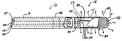
- FIG. 1is a schematic over-view of an ablation system according to one embodiment of the present invention.
- FIG. 1illustrates the ablation system including an RF ablation catheter 10 an electro-surgical unit 46 , which includes an RF energy source, and a conductive fluid source 44 ;
- ablation catheter 10includes an elongated, flexible, catheter shaft or body 18 extending from a distal virtual electrode assembly 12 , coupled to a distal segment 16 of body 18 , to a proximal handle 14 , which couples catheter 10 to electro-surgical unit 46 , via electrical terminals 6 , and to conductive fluid source 44 , via a port 26 .
- FIG. 1further illustrates catheter 10 including one or more ring-shaped mapping electrodes 72 positioned about body 18 proximal to virtual electrode 12 .
- Catheter body 18may be of any suitable diameter and length and may be straight or pre-curved along its length. According to one embodiment, catheter body 18 has a uniform outside diameter of about 0.052 inch (1.32 mm) to about 0.1040 inch (2.64 mm) and a length of about 50 cm to about 110 cm. Catheter body 18 may be formed in any of the manners known in the art to include a plurality of lumens ( FIG. 2 ) extending from handle 14 to catheter body distal segment 16 accommodating fluid delivery, electrical conductors, push-pull wire(s), and a torque wire, for example.
- Handle 14 coupled to a proximal end 22 of the catheter body 18may take any of the forms known in the art and includes a mechanism for deflecting a distal segment of the catheter body 18 into a curve to facilitate transvenous introduction of virtual electrode assembly 12 into a heart chamber and then directing it to a target ablation site.
- the mechanism illustrated in FIG. 1may take any of the forms known in the art and includes a mechanism for deflecting a distal segment of the catheter body 18 into a curve to facilitate transvenous introduction of virtual electrode assembly 12 into a heart chamber and then directing it to a target ablation site. The mechanism illustrated in FIG.
- 1includes an axially slidable ring 28 coupled to a proximal end of a curve deflection push-pull wire (not shown) and a rotatable lateral deflection or torque ring 24 coupled to a proximal end of a lateral deflection wire (not shown); torque ring 24 may be rotated to impart a torque in the lateral deflection wire coupled thus rotating distal segment 16 with respect to a longitudinal axis of catheter body 18 .
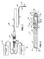
- FIG. 2is an enlarged plan view with partial section detailing a distal end of distal segment 16 of ablation catheter 10 shown in FIG. 1 .
- FIG. 2illustrates virtual electrode assembly 12 terminating the distal end of distal segment 16 and including a non-conductive, outer cap 30 fixed over an inner electrode 50 ; according to embodiments of the present invention a fluid chamber 60 , facilitating ionic charging of conductive fluid, having fixed dimensions is maintained between an outer surface of electrode 50 and an inner surface of outer cap 30 .
- catheter body 18includes a fluid lumen 58 in fluid communication with an interior fluid trunk 52 of electrode 50 through which the conductive fluid is delivered (from fluid source 44 illustrated in FIG.
- FIG. 2further illustrates a thermocouple 55 positioned in proximity to the exterior surface of electrode 50 in order to monitor the temperature of fluid filling chamber 60 ; according to one embodiment a groove is formed in the exterior surface of electrode 50 to hold thermocouple 55 .
- FIG. 3is an enlarged plan view of a virtual electrode assembly according to an embodiment of the present invention.
- FIG. 3illustrates plurality of pores 32 arrayed longitudinally and circumferentially around all sides of cap 30 , including a dome-shaped distal end region 38 , to enable emission of the conductive fluid out from cap 30 both in a 360° pattern around a circumference of cap 30 , along a length of cap 30 , and axially out from distal end region 38 of cap 30 .
- distal end region 38may be a more blunt shape or a more tapered shape.
- cap 30is about 0.3 inch in length, about 0.09 inch in outer diameter, and about 0.08 inch in inner diameter; pores 32 are sized to allow passage of charged conductive fluid 40 ( FIG. 2 ) while preventing external blood platelets and proteins from blocking pores 32 or entering fluid chamber 60 ( FIG. 2 ), according to one embodiment, but are larger, for example between 0.0005 inch and 0.005 inch according to an alternate embodiment. Pores 32 may be formed through cap wall 34 , for example, by laser drilling, chemical etching or sintering, in a uniform pattern as illustrated or in a more random pattern; furthermore pore sizes among plurality of pores 32 may be uniform or vary.
- Cap 30may be formed of a rigid plastic, such as PEEK, or of a ceramic; in any case cap 30 is preferably a biocompatible material resistant to high temperatures associated with RF ablation, additional examples of which include but are not limited to injection grade plastics, fluoropolymers, such as PTFE, e-PTFE, and FEP.
- FIG. 4is a cross-section view along section line 4 — 4 shown in FIG. 3 .
- FIG. 4illustrates electrode 50 including fluid trunk 52 , radially extending fluid branches 54 and a distally extending fluid branch 62 to deliver conductive fluid to fluid chamber 60 formed between exterior surface 56 of electrode 50 and an inner surface 36 of cap 30 from which charged conductive fluid 40 ( FIG. 2 ) is emitted through pores 32 .
- Electrode 50may be formed from any appropriate electrode material examples of which include, but are not limited to, stainless steels and platinum-iridium alloys.
- a diameter of trunk 52ranges between approximately 0.005 inch approximately 0.030 inch and diameters of branches 54 , 62 range between approximately 0.005 inch and approximately 0.030 inch; the trunk and branch diameters may be varied according to various performance requirements requiring different distributions of fluid flow.
- electrode 50also includes a proximal spacer 64 , extending circumferentially about, and outward from exterior surface 56 , and a distal spacer 66 , extending distally from exterior surface 56 at a distal end of electrode 50 .
- spacers 64 , 66contact an inner surface 36 of outer cap 30 as means to maintain a fixed, annular, fluid chamber 60 between exterior surface 56 of electrode 50 and inner surface 36 of outer cap 30 facilitating ionic charging of conductive fluid by RF energy delivered to electrode 50 .
- virtual electrode assembly 12results a consistent volume, fixed fluid chamber 60 providing a consistent emission of charged conductive fluid 40 through pores 32 of outer cap 30 .
- a width of chamber 60(a maximum distance between exterior surface 56 of electrode 50 and inner surface 36 of cap 30 ) is between approximately 0.003 inch and approximately 0.005 inch.
- FIG. 4illustrates distally extending fluid branch extending through distal spacer in fluid communication with a larger hole 39 through wall 34 of end cap 30 , according to an alternate embodiment, as illustrated in FIG. 6 pores 32 extend over this region.
- FIG. 4further illustrates outer cap 30 including a first detent 74 and a second detent 76 ; according to embodiments of the present invention first detent 74 serves to couple cap 30 to electrode 50 by engaging proximal spacer 64 while second detent 76 serves as means to couple cap 30 and electrode 50 to catheter body 18 by engaging a connector ring 70 , which is coupled to catheter body 18 as illustrated in FIG. 2 . According to an alternate embodiment outer cap 30 is coupled to electrode 50 by means of a friction fit with proximal spacer 64 and/or other spacers extending outward from exterior surface 56 of electrode 50 .
- a push-pull wireextends from a connection with connector ring 70 through a lumen 47 of body 18 to a connection with slide ring 28 on handle 14 and a torque wire (not shown) extends from a connection with connector ring 70 through a lumen 48 to a connection with torque ring 24 on handle 14 .
- electrode 50 , thermocouple 55 and one or more mapping electrodes 72are coupled to electro-surgical unit 46 via electrical conductors (not shown) extending through a lumen 49 of catheter body 18 to a connection with electrical terminals 6 of handle 14 .
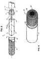
- FIG. 5is an exploded perspective view of a virtual electrode assembly according to one embodiment of the present invention. According to embodiments of the present invention, FIG. 5 illustrates means by which virtual electrode assembly is assembled onto catheter body 18 , wherein connector ring 70 is fitted into a distal end 110 of body 18 , electrode 50 is fitted into connector ring, and cap 30 is fitted over electrode 50 and a distal portion of connector ring 70 .
- Electrode 50may be coupled to ring 70 prior to or after coupling with catheter body 18 in a manner providing electrical coupling between conductors delivering RF energy and electrode 50 , e.g. welding.
- Cap 30is assembled over electrode 50 and pushed proximally until second detent 76 engages ring 70 and first detent engages proximal spacer 64 .
- a tubing band in conjunction with adhesive bonding or ultrasonic weldingmay be employed to secure the junction between electrode assembly 12 and catheter body 18 .
- FIG. 6is a perspective end view of a virtual electrode according to an embodiment of the present invention wherein a density of pores 32 is increased in distal end region 38 of cap 30 , thus concentrating delivery of conductive fluid 40 distally to facilitate both a formation of a discrete lesion and a formation of an elongated lesion by means of pushing or dragging distal end region 38 over the tissue to be ablated.
- FIG. 7is a plan view with partial section of a virtual electrode assembly according to an alternate embodiment of the present invention.
- FIG. 7illustrates an exterior surface 56 ′ of an electrode 50 ′ including extensions formed as ridges or a spiral coil 80 as means to increase an exterior surface area of electrode 50 ′.
- FIG. 7further illustrates an alternative spiral pattern of fluid branches 54 ′ extending from an interior fluid trunk, e.g. trunk 52 shown in FIG. 4 , to exterior surface 56 ′ within spiral valleys between turns of spiral coil 80 .
Landscapes
- Health & Medical Sciences (AREA)
- Life Sciences & Earth Sciences (AREA)
- Surgery (AREA)
- Engineering & Computer Science (AREA)
- Plasma & Fusion (AREA)
- Medical Informatics (AREA)
- Otolaryngology (AREA)
- Physics & Mathematics (AREA)
- Cardiology (AREA)
- Biomedical Technology (AREA)
- Heart & Thoracic Surgery (AREA)
- Nuclear Medicine, Radiotherapy & Molecular Imaging (AREA)
- Molecular Biology (AREA)
- Animal Behavior & Ethology (AREA)
- General Health & Medical Sciences (AREA)
- Public Health (AREA)
- Veterinary Medicine (AREA)
- Surgical Instruments (AREA)
Abstract
Description
The present invention relates generally to an electrophysiology (EP) catheter for use in radiofrequency (RF) ablation, particularly an RF ablation catheter including a virtual electrode delivering ablation energy through conductive fluid emitted from a porous tip.
Therapies have been developed for treating atrial and ventricular tachycardias by destroying cardiac tissue containing an identified ectopic foci or an aberrant conduction pathway; one of these therapies includes the application of ablative RF energy delivered through a catheter, which may be introduced transvenously into the heart, to a target site via a virtual electrode formed by conductive fluid infused out from a portion of the catheter in proximity to the site. An ablation electrode contained within that portion of the catheter and shielded by a non-conductive porous shell energizes the infused fluid; the rate of infusion and conductivity of the fluid can be controlled to work in conjunction with various electrodes with different surface areas. The creation of the virtual electrode enables the current to flow with reduced resistance or impedance throughout a larger volume of tissue, thus spreading the resistive heating created by the current flow through a larger volume of tissue and thereby creating a larger lesion than could otherwise be created with a ‘dry’ electrode. Furthermore, virtual electrodes reduce the potential for complications arising from an excessive electrode temperature (approximately greater than 100 degrees Celsius), typically associated with ‘dry’ ablation electrodes in direct contact with the target site, which may cause formation of blood coagulum and sub-surface explosions or pops within the tissue.
Physicians have long used the technique of pressing an RF electrode, which terminates a distal end of a catheter, against the endocardium, applying RF energy, and dragging the electrode along the endocardium to create an elongated lesion. Consequently, there remains a need for an improved RF ablation catheter including a virtual electrode assembly that is simple to fabricate and to use efficaciously in this manner.
The following drawings are illustrative of particular embodiments of the invention and therefore do not limit its scope, but are presented to assist in providing a proper understanding of the invention. The drawings are not to scale (unless so stated) and are intended for use in conjunction with the explanations in the following detailed description. The present invention will hereinafter be described in conjunction with the appended drawings, wherein like numerals denote like elements, and:
The following detailed description is exemplary in nature and is not intended to limit the scope, applicability, or configuration of the invention in any way. Rather, the following description provides a practical illustration for implementing exemplary embodiments of the invention.
As further illustrated inFIG. 4 ,electrode 50 also includes aproximal spacer 64, extending circumferentially about, and outward fromexterior surface 56, and adistal spacer 66, extending distally fromexterior surface 56 at a distal end ofelectrode 50. According to embodiments of thepresent invention spacers inner surface 36 ofouter cap 30 as means to maintain a fixed, annular,fluid chamber 60 betweenexterior surface 56 ofelectrode 50 andinner surface 36 ofouter cap 30 facilitating ionic charging of conductive fluid by RF energy delivered toelectrode 50. Thus,virtual electrode assembly 12 results a consistent volume,fixed fluid chamber 60 providing a consistent emission of charged conductive fluid40 throughpores 32 ofouter cap 30. According to an exemplary embodiment, a width of chamber60 (a maximum distance betweenexterior surface 56 ofelectrode 50 andinner surface 36 of cap30) is between approximately 0.003 inch and approximately 0.005 inch. AlthoughFIG. 4 illustrates distally extending fluid branch extending through distal spacer in fluid communication with a larger hole39 throughwall 34 ofend cap 30, according to an alternate embodiment, as illustrated inFIG. 6 pores 32 extend over this region.
Referring back toFIGS. 1 and 2 , according to one embodiment, a push-pull wire (not shown) extends from a connection withconnector ring 70 through alumen 47 ofbody 18 to a connection withslide ring 28 onhandle 14 and a torque wire (not shown) extends from a connection withconnector ring 70 through alumen 48 to a connection withtorque ring 24 onhandle 14. Furthermore,electrode 50,thermocouple 55 and one ormore mapping electrodes 72 are coupled to electro-surgical unit 46 via electrical conductors (not shown) extending through alumen 49 ofcatheter body 18 to a connection with electrical terminals6 ofhandle 14.
It will be understood that certain of the above-described structures, functions and operations of the above-described embodiments are not necessary to practice the present invention and are included in the description simply for completeness of an exemplary embodiment or embodiments. Thus, it is expected that various changes, alterations, or modifications may be made to the invention as described herein without departing from the spirit and scope of the invention as defined by the appended claims.
Claims (44)
1. An ablation catheter comprising:
an elongated catheter body extending between a catheter body proximal end and a catheter body distal end, the elongated catheter body including elongated electrical conductors extending between the catheter body proximal end and the catheter body distal end, a fluid port positioned in proximity to the catheter body proximal end and a fluid delivery lumen extending between the port and the catheter body distal end; and
a virtual electrode assembly terminating the catheter body distal end and including an inner electrode electrically coupled to the elongated conductors, a non-conductive outer cap fixed over the electrode and a fluid chamber formed between the inner electrode and the outer cap;
wherein the outer cap includes a cap inner surface, a cap outer surface and a plurality of pores extending between the cap inner surface and the cap outer surface;
the inner electrode includes an interior fluid trunk in fluid communication with the fluid delivery lumen of the catheter body, an exterior surface, one or more fluid distribution branches extending from the fluid trunk to the exterior surface, and one or more spacers protruding from the exterior surface and contacting the cap inner surface to maintain the fluid chamber between the inner electrode and the outer cap;
a connector ring facilitating coupling of the virtual electrode assembly to the catheter body distal end;
means for coupling the outer cap to the electrode assembly by engaging the one or more spacers of the inner electrode; and
when the inner electrode is energized, via the elongated conductor, and a conductive fluid is delivered through the one or more fluid distribution branches from the fluid trunk, supplied by the fluid delivery lumen of the catheter, the conductive fluid fills the fluid chamber and flows out from the chamber through the plurality of pores of the cap establishing ionic transport of ablation energy from the inner electrode to a target site in close proximity to the cap.
2. The ablation catheter ofclaim 1 , wherein the outer cap further includes a dome-shaped distal end region.
3. The ablation catheter ofclaim 1 , wherein the coupling means comprises one or more detents on the outer cap engaging the one or more spacers of the inner electrode.
4. The ablation catheter ofclaim 1 , wherein the outer cap further includes a detent engaging the connector ring.
5. The ablation catheter ofclaim 1 , wherein the outer cap is formed of a material comprising a rigid plastic.
6. The ablation catheter ofclaim 1 , wherein the outer cap is formed of a material comprising a fluoro-polymer.
7. The ablation catheter ofclaim 1 , wherein the outer cap is formed of a material comprising an epoxy resin.
8. The ablation catheter ofclaim 1 , wherein the plurality of pores are arrayed longitudinally along a length of the outer cap and circumferentially 360 degrees around the outer cap.
9. The ablation catheter ofclaim 1 , wherein the plurality of pores are arrayed longitudinally along a length of the outer cap and circumferentially 360 degrees around the outer cap extending over the dome-shaped distal end region.
10. The ablation catheter ofclaim 1 , wherein a maximum diameter of each of the plurality of pores is sized to prevent ingress of blood cells into the fluid chamber from the cap outer surface.
11. The ablation catheter ofclaim 1 , wherein a maximum diameter of each of the plurality of pores is between approximately 0.0005 inch and 0.005 inch.
12. The ablation catheter ofclaim 1 , wherein the plurality of pores is formed by a process selected from the group consisting of laser drilling, chemical etching and sintering.
13. The ablation catheter ofclaim 1 , wherein the exterior surface of the electrode includes extensions increasing a surface area of the exterior surface.
14. The ablation catheter ofclaim 13 , wherein the extensions form a spiral coil.
15. The ablation catheter ofclaim 1 , wherein the one or more spacers extend circumferentially about a proximal end of the electrode.
16. The ablation catheter ofclaim 1 , wherein the one or more spacers extend distally from a distal end of the electrode.
17. The ablation catheter ofclaim 1 , wherein one of the one or more fluid distribution branches passes through a distal end of the electrode.
18. The ablation catheter ofclaim 17 , wherein the one of the one or more spacers extends distally from a distal end of the electrode.
19. The ablation catheter ofclaim 18 , wherein the cap further includes a hole extending from the cap inner surface to the cap outer surface and generally aligned and in fluid communication with the one of the one or more fluid distribution branches.
20. The ablation catheter ofclaim 1 , wherein a diameter of the fluid trunk of the electrode is between approximately 0.005 inch and approximately 0.030 inch.
21. The ablation catheter ofclaim 1 , wherein a diameter of each of the one or more fluid distribution branches is between approximately 0.005 inch and approximately 0.030 inch.
22. An ablation catheter comprising:
an elongated catheter body extending between a catheter body proximal end and a catheter body distal end, the elongated catheter body including elongated electrical conductors extending between the catheter body proximal end and the catheter body distal end, a fluid port positioned in proximity to the catheter body proximal end and a fluid delivery lumen extending between the port and the catheter body distal end; and
a virtual electrode assembly terminating the catheter body distal end and including an inner electrode electrically coupled to the elongated conductors, a non-conductive outer cap fixed over the electrode and a fluid chamber formed between the inner electrode and the outer cap;
wherein the outer cap includes a cap inner surface, a cap outer surface and a plurality of pores extending between the cap inner surface and the cap outer surface;
the inner electrode includes an interior fluid trunk in fluid communication with the fluid delivery lumen of the catheter body, an exterior surface, one or more fluid distribution branches extending from the fluid trunk to the exterior surface, and one or more spacers protruding from the exterior surface and contacting the cap inner surface to maintain the fluid chamber between the inner electrode and the outer cap;
means for coupling the outer cap to the electrode assembly by engaging the one or more spacers of the inner electrode; and
when the inner electrode is energized, via the elongated conductor, and a conductive fluid is delivered through the one or more fluid distribution branches from the fluid trunk, supplied by the fluid delivery lumen of the catheter, the conductive fluid fills the fluid chamber and flows out from the chamber through the plurality of pores of the cap establishing ionic transport of ablation energy from the inner electrode to a target site in close proximity to the cap, wherein the outer cap is formed of a material comprising a ceramic.
23. An ablation catheter comprising:
an elongated catheter body extending between a catheter body proximal end and a catheter body distal end, the elongated catheter body including elongated electrical conductors extending between the catheter body proximal end and the catheter body distal end, a fluid port positioned in proximity to the catheter body proximal end and a fluid delivery lumen extending between the port and the catheter body distal end; and
a virtual electrode assembly terminating the catheter body distal end and including an inner electrode electrically coupled to the elongated conductors, a non-conductive outer cap fixed over the electrode and a fluid chamber formed between the inner electrode and the outer cap;
wherein the outer cap includes a cap inner surface, a cap outer surface and a plurality of pores extending between the cap inner surface and the cap outer surface;
the inner electrode includes an interior fluid trunk in fluid communication with the fluid delivery lumen of the catheter body, an exterior surface, one or more fluid distribution branches extending from the fluid trunk to the exterior surface, and one or more spacers protruding from the exterior surface and contacting the cap inner surface to maintain the fluid chamber between the inner electrode and the outer cap;
means for coupling the outer cap to the electrode assembly by engaging the one or more spacers of the inner electrode; and
when the inner electrode is energized, via the elongated conductor, and a conductive fluid is delivered through the one or more fluid distribution branches from the fluid trunk, supplied by the fluid delivery lumen of the catheter, the conductive fluid fills the fluid chamber and flows out from the chamber through the plurality of pores of the cap establishing ionic transport of ablation energy from the inner electrode to a target site in close proximity to the cap, wherein a maximum distance between the exterior surface of the electrode and the cap inner surface is between approximately 0.003 inch and approximately 0.005 inch.
24. A virtual ablation electrode assembly, comprising:
a non-conductive outer cap including a cap inner surface, a cap outer surface and a plurality of pores extending between the cap inner surface and the cap outer surface;
an inner electrode including an interior fluid trunk, an exterior surface, one or more fluid distribution branches extending from the fluid trunk to the exterior surface, and one or more spacers protruding from the exterior surface and contacting the cap inner surface;
means for coupling the outer cap to the electrode assembly by engaging the one or more spacers of the inner electrode; and
a fluid chamber formed between the inner electrode and the outer cap and maintained by the one more spacers;
wherein, when the electrode is energized and when fluid is delivered through the one or more fluid distribution branches from the trunk, the conductive fluid fills the fluid chamber and flows out from the chamber through the plurality of pores of the cap establishing ionic transport of ablation energy from the inner electrode to a target site in close proximity to the cap, and wherein the coupling means comprises one or more detents on the outer cap engaging the one or more spacers of the inner electrode.
25. The virtual ablation electrode assembly ofclaim 24 , wherein the outer cap further includes a dome-shaped distal end region.
26. The virtual ablation electrode assembly ofclaim 24 , wherein the outer cap is formed of a material comprising a rigid plastic.
27. The virtual ablation electrode assembly ofclaim 24 , wherein the outer cap is formed of a material comprising a ceramic.
28. The virtual ablation electrode assembly ofclaim 24 , wherein the outer cap is formed of a material comprising a fluoro-polymer.
29. The virtual ablation electrode assembly ofclaim 24 , wherein the outer cap is formed of a material comprising an epoxy resin.
30. The virtual ablation electrode assembly ofclaim 24 , wherein the plurality of pores are arrayed longitudinally along a length of the outer cap and circumferentially 360 degrees around the outer cap.
31. The virtual ablation electrode assembly ofclaim 25 , wherein the plurality of pores are arrayed longitudinally along a length of the outer cap and circumferentially 360 degrees around the outer cap extending over the dome-shaped distal end region.
32. The virtual ablation electrode assembly ofclaim 24 , wherein a maximum diameter of each of the plurality of pores is sized to prevent ingress of blood cells into the fluid chamber from the cap outer surface.
33. The ablation catheter ofclaim 24 , wherein a maximum diameter of each of the plurality of pores is between approximately 0.0005 inch and 0.005 inch.
34. The virtual ablation electrode assembly ofclaim 24 , wherein the plurality of pores is formed by a process selected from the group consisting of laser drilling, chemical etching and sintering.
35. The virtual ablation electrode assembly ofclaim 24 , wherein a maximum distance between the exterior surface of the electrode and the cap inner surface is between approximately 0.003 inch and approximately 0.005 inch.
36. The virtual ablation electrode assembly ofclaim 24 , wherein the exterior surface of the electrode includes extensions increasing a surface area of the exterior surface.
37. The virtual ablation electrode assembly ofclaim 36 , wherein the extensions form a spiral coil.
38. The virtual ablation electrode assembly ofclaim 24 , wherein the one or more spacers extend circumferentially about a proximal end of the electrode.
39. The virtual ablation electrode assembly ofclaim 24 , wherein the one or more spacers extend distally from a distal end of the electrode.
40. The virtual ablation electrode assembly ofclaim 24 , wherein one of the one or more fluid distribution branches passes through a distal end of the electrode.
41. The virtual ablation electrode assembly ofclaim 40 , wherein the one of the one or more spacers extends distally from a distal end of the electrode.
42. The virtual ablation electrode assembly ofclaim 41 , wherein the cap further includes a hole extending from the cap inner surface to the cap outer surface and generally aligned and in fluid communication with the one of the one or more fluid distribution branches.
43. The virtual ablation electrode assembly ofclaim 24 , wherein a diameter of the fluid trunk of the electrode is between approximately 0.005 inch and approximately 0.030 inch.
44. The virtual ablation electrode assembly ofclaim 24 , wherein a diameter of each of the one or more fluid distribution branches is between approximately 0.005 inch and approximately 0.030 inch.
Priority Applications (1)
| Application Number | Priority Date | Filing Date | Title |
|---|---|---|---|
| US10/656,422US7104989B2 (en) | 2003-09-05 | 2003-09-05 | RF ablation catheter including a virtual electrode assembly |
Applications Claiming Priority (1)
| Application Number | Priority Date | Filing Date | Title |
|---|---|---|---|
| US10/656,422US7104989B2 (en) | 2003-09-05 | 2003-09-05 | RF ablation catheter including a virtual electrode assembly |
Publications (2)
| Publication Number | Publication Date |
|---|---|
| US20050055019A1 US20050055019A1 (en) | 2005-03-10 |
| US7104989B2true US7104989B2 (en) | 2006-09-12 |
Family
ID=34226331
Family Applications (1)
| Application Number | Title | Priority Date | Filing Date |
|---|---|---|---|
| US10/656,422Expired - Fee RelatedUS7104989B2 (en) | 2003-09-05 | 2003-09-05 | RF ablation catheter including a virtual electrode assembly |
Country Status (1)
| Country | Link |
|---|---|
| US (1) | US7104989B2 (en) |
Cited By (58)
| Publication number | Priority date | Publication date | Assignee | Title |
|---|---|---|---|---|
| US20070043349A1 (en)* | 2005-08-19 | 2007-02-22 | Boston Scientific Scimed, Inc. | Occlusion apparatus |
| US20070156132A1 (en)* | 2005-12-30 | 2007-07-05 | Darrell Drysen | Injection molded irrigated tip electrode and catheter having the same |
| US20070208334A1 (en)* | 2006-03-02 | 2007-09-06 | Arthrocare Corporation | Internally located return electrode electrosurgical apparatus, system and method |
| US20080045941A1 (en)* | 2006-08-17 | 2008-02-21 | Fugo Richard J | Method and apparatus for plasma incision of cardiovascular tissue |
| US20080234603A1 (en)* | 2007-03-19 | 2008-09-25 | Ethicon Endo-Surgery, Inc. | Electrode dome and method of use |
| US7462178B2 (en) | 2000-05-12 | 2008-12-09 | Arthrocare Corporation | Systems and methods for electrosurgical spine surgery |
| US20090281538A1 (en)* | 2005-12-23 | 2009-11-12 | Evan Chong | Irrigation catheter |
| US20100030209A1 (en)* | 2008-07-15 | 2010-02-04 | Assaf Govari | Catheter with perforated tip |
| US7699805B2 (en) | 1998-07-07 | 2010-04-20 | Medtronic, Inc. | Helical coil apparatus for ablation of tissue |
| US7708733B2 (en) | 2003-10-20 | 2010-05-04 | Arthrocare Corporation | Electrosurgical method and apparatus for removing tissue within a bone body |
| US7794456B2 (en) | 2003-05-13 | 2010-09-14 | Arthrocare Corporation | Systems and methods for electrosurgical intervertebral disc replacement |
| US20100256637A1 (en)* | 2009-04-03 | 2010-10-07 | Device Evolutions, Llc | Laparoscopic Nephrectomy Device |
| WO2011141800A1 (en) | 2010-05-10 | 2011-11-17 | Endosense S.A. | Irrigated finned ablation head |
| US20130030385A1 (en)* | 2011-07-30 | 2013-01-31 | Schultz Jeffrey W | Catheter with flow balancing valve |
| US8551088B2 (en) | 2008-03-31 | 2013-10-08 | Applied Medical Resources Corporation | Electrosurgical system |
| US8979838B2 (en) | 2010-05-24 | 2015-03-17 | Arthrocare Corporation | Symmetric switching electrode method and related system |
| EP2913017A1 (en)* | 2014-02-27 | 2015-09-02 | Osypka Ag. | Irrigated ablation catheter |
| US9220433B2 (en) | 2011-06-30 | 2015-12-29 | Biosense Webster (Israel), Ltd. | Catheter with variable arcuate distal section |
| USD748259S1 (en) | 2014-12-29 | 2016-01-26 | Applied Medical Resources Corporation | Electrosurgical instrument |
| US9320563B2 (en) | 2010-10-01 | 2016-04-26 | Applied Medical Resources Corporation | Electrosurgical instruments and connections thereto |
| US9510894B2 (en) | 2010-04-28 | 2016-12-06 | Biosense Webster (Israel) Ltd. | Irrigated ablation catheter having irrigation ports with reduced hydraulic resistance |
| US9724151B2 (en) | 2013-08-08 | 2017-08-08 | Relievant Medsystems, Inc. | Modulating nerves within bone using bone fasteners |
| US9724107B2 (en) | 2008-09-26 | 2017-08-08 | Relievant Medsystems, Inc. | Nerve modulation systems |
| US9775627B2 (en) | 2012-11-05 | 2017-10-03 | Relievant Medsystems, Inc. | Systems and methods for creating curved paths through bone and modulating nerves within the bone |
| US9839472B2 (en) | 2015-10-29 | 2017-12-12 | Innoblative Designs, Inc. | Screen sphere tissue ablation devices and methods |
| US9855098B2 (en) | 2015-04-29 | 2018-01-02 | Innoblative Designs, Inc. | Cavitary tissue ablation |
| US9943363B2 (en) | 2010-04-28 | 2018-04-17 | Biosense Webster, Inc. | Irrigated ablation catheter with improved fluid flow |
| US9943362B2 (en) | 2010-04-28 | 2018-04-17 | Biosense Webster, Inc. | Irrigated ablation catheter with improved fluid flow |
| US9949791B2 (en) | 2010-04-26 | 2018-04-24 | Biosense Webster, Inc. | Irrigated catheter with internal position sensor |
| US10022183B2 (en) | 2014-04-01 | 2018-07-17 | Innovations In Medicine, Llc | Temperature-responsive irrigated ablation electrode with reduced coolant flow and related methods for making and using |
| US10034707B2 (en) | 2014-12-30 | 2018-07-31 | Biosense Webster (Israel) Ltd. | Catheter with irrigated tip electrode with porous substrate and high density surface micro-electrodes |
| US10070921B2 (en) | 2016-10-17 | 2018-09-11 | Innoblative Designs, Inc. | Treatment devices and methods |
| US10111704B2 (en) | 2002-09-30 | 2018-10-30 | Relievant Medsystems, Inc. | Intraosseous nerve treatment |
| US10149713B2 (en) | 2014-05-16 | 2018-12-11 | Applied Medical Resources Corporation | Electrosurgical system |
| US10265099B2 (en) | 2008-09-26 | 2019-04-23 | Relievant Medsystems, Inc. | Systems for accessing nerves within bone |
| US10376308B2 (en) | 2015-02-05 | 2019-08-13 | Axon Therapies, Inc. | Devices and methods for treatment of heart failure by splanchnic nerve ablation |
| US10390877B2 (en) | 2011-12-30 | 2019-08-27 | Relievant Medsystems, Inc. | Systems and methods for treating back pain |
| US10420603B2 (en) | 2014-12-23 | 2019-09-24 | Applied Medical Resources Corporation | Bipolar electrosurgical sealer and divider |
| US10463423B2 (en) | 2003-03-28 | 2019-11-05 | Relievant Medsystems, Inc. | Thermal denervation devices and methods |
| US10561461B2 (en) | 2017-12-17 | 2020-02-18 | Axon Therapies, Inc. | Methods and devices for endovascular ablation of a splanchnic nerve |
| US10588691B2 (en) | 2012-09-12 | 2020-03-17 | Relievant Medsystems, Inc. | Radiofrequency ablation of tissue within a vertebral body |
| US10792092B2 (en) | 2014-05-30 | 2020-10-06 | Applied Medical Resources Corporation | Electrosurgical seal and dissection systems |
| US10864039B2 (en) | 2016-02-02 | 2020-12-15 | Innoblative Designs, Inc. | Cavitary tissue ablation system |
| US10869714B2 (en) | 2016-03-01 | 2020-12-22 | Innoblative Designs, Inc. | Resecting and coagulating tissue |
| US10912602B2 (en) | 2016-11-08 | 2021-02-09 | Innoblative Designs, Inc. | Electrosurgical tissue and vessel sealing device |
| USRE48460E1 (en) | 2002-09-30 | 2021-03-09 | Relievant Medsystems, Inc. | Method of treating an intraosseous nerve |
| US11007010B2 (en) | 2019-09-12 | 2021-05-18 | Relevant Medsysterns, Inc. | Curved bone access systems |
| US11154354B2 (en) | 2016-07-29 | 2021-10-26 | Axon Therapies, Inc. | Devices, systems, and methods for treatment of heart failure by splanchnic nerve ablation |
| US11413090B2 (en) | 2020-01-17 | 2022-08-16 | Axon Therapies, Inc. | Methods and devices for endovascular ablation of a splanchnic nerve |
| US11696796B2 (en) | 2018-11-16 | 2023-07-11 | Applied Medical Resources Corporation | Electrosurgical system |
| US11751939B2 (en) | 2018-01-26 | 2023-09-12 | Axon Therapies, Inc. | Methods and devices for endovascular ablation of a splanchnic nerve |
| US11786297B2 (en) | 2017-07-26 | 2023-10-17 | Innoblative Designs, Inc. | Minimally invasive articulating assembly having ablation capabilities |
| US11806073B2 (en) | 2019-06-20 | 2023-11-07 | Axon Therapies, Inc. | Methods and devices for endovascular ablation of a splanchnic nerve |
| US11864812B2 (en) | 2018-09-05 | 2024-01-09 | Applied Medical Resources Corporation | Electrosurgical generator control system |
| US12039731B2 (en) | 2020-12-22 | 2024-07-16 | Relievant Medsystems, Inc. | Prediction of candidates for spinal neuromodulation |
| US12082876B1 (en) | 2020-09-28 | 2024-09-10 | Relievant Medsystems, Inc. | Introducer drill |
| US12207863B2 (en) | 2015-10-29 | 2025-01-28 | Innoblative Designs, Inc. | Screen sphere tissue ablation devices and methods |
| US12433668B1 (en) | 2021-11-08 | 2025-10-07 | Relievant Medsystems, Inc. | Impedance stoppage mitigation during radiofrequency tissue ablation procedures |
Families Citing this family (46)
| Publication number | Priority date | Publication date | Assignee | Title |
|---|---|---|---|---|
| US20070066972A1 (en)* | 2001-11-29 | 2007-03-22 | Medwaves, Inc. | Ablation catheter apparatus with one or more electrodes |
| US7811282B2 (en) | 2000-03-06 | 2010-10-12 | Salient Surgical Technologies, Inc. | Fluid-assisted electrosurgical devices, electrosurgical unit with pump and methods of use thereof |
| US6953461B2 (en) | 2002-05-16 | 2005-10-11 | Tissuelink Medical, Inc. | Fluid-assisted medical devices, systems and methods |
| US8048070B2 (en) | 2000-03-06 | 2011-11-01 | Salient Surgical Technologies, Inc. | Fluid-assisted medical devices, systems and methods |
| US6558385B1 (en) | 2000-09-22 | 2003-05-06 | Tissuelink Medical, Inc. | Fluid-assisted medical device |
| US6689131B2 (en) | 2001-03-08 | 2004-02-10 | Tissuelink Medical, Inc. | Electrosurgical device having a tissue reduction sensor |
| ES2306706T3 (en) | 2000-03-06 | 2008-11-16 | Salient Surgical Technologies, Inc. | FLUID SUPPLY SYSTEM AND CONTROLLER FOR ELECTROCHURGICAL DEVICES. |
| AU2002357166A1 (en) | 2001-12-12 | 2003-06-23 | Tissuelink Medical, Inc. | Fluid-assisted medical devices, systems and methods |
| WO2004039416A2 (en) | 2002-10-29 | 2004-05-13 | Tissuelink Medical, Inc. | Fluid-assisted electrosurgical scissors and methods |
| US6984232B2 (en) | 2003-01-17 | 2006-01-10 | St. Jude Medical, Daig Division, Inc. | Ablation catheter assembly having a virtual electrode comprising portholes |
| US7387629B2 (en) | 2003-01-21 | 2008-06-17 | St. Jude Medical, Atrial Fibrillation Division, Inc. | Catheter design that facilitates positioning at tissue to be diagnosed or treated |
| US6960207B2 (en) | 2003-01-21 | 2005-11-01 | St Jude Medical, Daig Division, Inc. | Ablation catheter having a virtual electrode comprising portholes and a porous conductor |
| US20050080410A1 (en)* | 2003-10-14 | 2005-04-14 | Scimed Life Systems, Inc. | Liquid infusion apparatus for radiofrequency tissue ablation |
| US7282051B2 (en)* | 2004-02-04 | 2007-10-16 | Boston Scientific Scimed, Inc. | Ablation probe for delivering fluid through porous structure |
| US7727232B1 (en) | 2004-02-04 | 2010-06-01 | Salient Surgical Technologies, Inc. | Fluid-assisted medical devices and methods |
| US7631297B2 (en)* | 2005-04-05 | 2009-12-08 | International Business Machines Corporation | Autonomic computing: management agent utilizing action policy for operation |
| US7419486B2 (en) | 2005-06-15 | 2008-09-02 | St. Jude Medical, Atrial Fibrillation Division, Inc. | Treatment and diagnostic catheters with hydrogel electrodes |
| US7776034B2 (en)* | 2005-06-15 | 2010-08-17 | St. Jude Medical, Atrial Fibrillation Division, Inc. | Ablation catheter with adjustable virtual electrode |
| US7819868B2 (en) | 2005-06-21 | 2010-10-26 | St. Jude Medical, Atrial Fibrilation Division, Inc. | Ablation catheter with fluid distribution structures |
| US7879030B2 (en) | 2005-07-27 | 2011-02-01 | St. Jude Medical, Atrial Fibrillation Division, Inc. | Multipolar, virtual-electrode catheter with at least one surface electrode and method for ablation |
| US7416552B2 (en) | 2005-08-22 | 2008-08-26 | St. Jude Medical, Atrial Fibrillation Division, Inc. | Multipolar, multi-lumen, virtual-electrode catheter with at least one surface electrode and method for ablation |
| US8864728B2 (en)* | 2008-12-31 | 2014-10-21 | Kci Licensing, Inc. | Multi-conduit manifolds, systems, and methods for applying reduced pressure to a subcutaneous tissue site |
| MX2011006993A (en)* | 2008-12-31 | 2011-08-04 | Kci Licensing Inc | Sleeves, manifolds, systems, and methods for applying reduced pressure to a subcutaneous tissue site. |
| WO2011066445A2 (en)* | 2009-11-30 | 2011-06-03 | Medwaves, Inc. | Radio frequency ablation system with tracking sensor |
| WO2011101778A1 (en)* | 2010-02-19 | 2011-08-25 | Koninklijke Philips Electronics N.V. | Ablation catheter and a method of performing ablation |
| US8652025B2 (en)* | 2010-10-19 | 2014-02-18 | Michael D. Laufer | Methods and devices for diastolic assist |
| US9855094B2 (en) | 2010-12-28 | 2018-01-02 | St. Jude Medical, Atrial Fibrillation Division, Inc. | Multi-rate fluid flow and variable power delivery for ablation electrode assemblies used in catheter ablation procedures |
| US8814857B2 (en) | 2010-12-17 | 2014-08-26 | St. Jude Medical, Atrial Filbrillation Division, Inc. | Irrigated ablation electrode assemblies |
| US9788891B2 (en)* | 2010-12-28 | 2017-10-17 | St. Jude Medical, Atrial Fibrillation Division, Inc. | Ablation electrode assemblies and methods for using same |
| ES2864589T3 (en) | 2011-04-12 | 2021-10-14 | Thermedical Inc | Devices for conformal therapy in fluid-enhanced ablation |
| US9717554B2 (en)* | 2012-03-26 | 2017-08-01 | Biosense Webster (Israel) Ltd. | Catheter with composite construction |
| US10022176B2 (en)* | 2012-08-15 | 2018-07-17 | Thermedical, Inc. | Low profile fluid enhanced ablation therapy devices and methods |
| US9144460B2 (en)* | 2012-12-31 | 2015-09-29 | Biosense Webster (Israel) Ltd. | Catheter with direct cooling on nonablating element |
| US9498112B1 (en) | 2013-03-15 | 2016-11-22 | Brent Stewart | Laryngoscope |
| US9033972B2 (en) | 2013-03-15 | 2015-05-19 | Thermedical, Inc. | Methods and devices for fluid enhanced microwave ablation therapy |
| US9610396B2 (en) | 2013-03-15 | 2017-04-04 | Thermedical, Inc. | Systems and methods for visualizing fluid enhanced ablation therapy |
| US10251698B2 (en)* | 2013-04-22 | 2019-04-09 | Cathrx Ltd | Ablation catheter |
| US20160361115A1 (en)* | 2015-06-10 | 2016-12-15 | Boston Scientific Scimed Inc. | Saline between tip and tissue |
| US9743984B1 (en) | 2016-08-11 | 2017-08-29 | Thermedical, Inc. | Devices and methods for delivering fluid to tissue during ablation therapy |
| US11559349B2 (en) | 2016-09-12 | 2023-01-24 | Biosense Webster (Israel) Ltd. | Ablation catheter with a flexible printed circuit board |
| US11911093B2 (en)* | 2016-09-12 | 2024-02-27 | Biosense Webster (Israel) Ltd. | Irrigation system for a catheter |
| US11083871B2 (en) | 2018-05-03 | 2021-08-10 | Thermedical, Inc. | Selectively deployable catheter ablation devices |
| US11918277B2 (en) | 2018-07-16 | 2024-03-05 | Thermedical, Inc. | Inferred maximum temperature monitoring for irrigated ablation therapy |
| WO2020052231A1 (en)* | 2018-09-14 | 2020-03-19 | 杭州堃博生物科技有限公司 | Radio frequency ablation catheter, radio frequency ablation system for lungs, and corresponding control method, control device, and computer-readable storage medium |
| PL3788974T3 (en)* | 2019-09-05 | 2025-02-10 | Erbe Elektromedizin Gmbh | ABLATION PROBE |
| US20230054269A1 (en)* | 2021-08-23 | 2023-02-23 | Biosense Webster (Israel) Ltd. | Basket Catheter with Porous Sheath |
Citations (20)
| Publication number | Priority date | Publication date | Assignee | Title |
|---|---|---|---|---|
| US4532924A (en)* | 1980-05-13 | 1985-08-06 | American Hospital Supply Corporation | Multipolar electrosurgical device and method |
| US5047028A (en)* | 1989-05-12 | 1991-09-10 | Quinghua Qian | Method for inducing thrombosis in blood vessels |
| US5643197A (en)* | 1993-12-21 | 1997-07-01 | Angeion Corporation | Fluid cooled and perfused tip for a catheter |
| US5846239A (en)* | 1996-04-12 | 1998-12-08 | Ep Technologies, Inc. | Tissue heating and ablation systems and methods using segmented porous electrode structures |
| US5913856A (en)* | 1997-05-19 | 1999-06-22 | Irvine Biomedical, Inc. | Catheter system having a porous shaft and fluid irrigation capabilities |
| US5919188A (en)* | 1997-02-04 | 1999-07-06 | Medtronic, Inc. | Linear ablation catheter |
| US6056747A (en)* | 1997-08-04 | 2000-05-02 | Gynecare, Inc. | Apparatus and method for treatment of body tissues |
| US6071278A (en) | 1996-02-28 | 2000-06-06 | Ep Technologies, Inc. | Tissue heating and ablation systems and methods using porous electrode structures with specified electrical resistivities |
| US6076012A (en)* | 1996-12-19 | 2000-06-13 | Ep Technologies, Inc. | Structures for supporting porous electrode elements |
| US6119041A (en)* | 1996-03-06 | 2000-09-12 | Cardiac Pathways Corporation | Apparatus and method for linear lesion ablation |
| US6120476A (en) | 1997-12-01 | 2000-09-19 | Cordis Webster, Inc. | Irrigated tip catheter |
| US6171275B1 (en) | 1998-12-03 | 2001-01-09 | Cordis Webster, Inc. | Irrigated split tip electrode catheter |
| US6277089B1 (en)* | 1990-07-24 | 2001-08-21 | Inbae Yoon | Method for ablating portions of the uterus |
| US20020128640A1 (en)* | 2001-03-07 | 2002-09-12 | Scimed Life Systems, Inc. | Internal indifferent electrode device for use with lesion creation apparatus and method of forming lesions using the same |
| US6466818B1 (en) | 1999-01-15 | 2002-10-15 | Biosense Webster, Inc. | Porous irrigated tip electrode catheter |
| US6497705B2 (en) | 1998-07-07 | 2002-12-24 | Medtronic, Inc. | Method and apparatus for creating a virtual electrode used for the ablation of tissue |
| US20030014048A1 (en)* | 2000-08-30 | 2003-01-16 | Swanson David K. | Fluid cooled apparatus for supporting diagnostic and therapeutic elements in contact with tissue |
| US6522930B1 (en) | 1998-05-06 | 2003-02-18 | Atrionix, Inc. | Irrigated ablation device assembly |
| US6537272B2 (en) | 1998-07-07 | 2003-03-25 | Medtronic, Inc. | Apparatus and method for creating, maintaining, and controlling a virtual electrode used for the ablation of tissue |
| US6673068B1 (en)* | 2000-04-12 | 2004-01-06 | Afx, Inc. | Electrode arrangement for use in a medical instrument |
- 2003
- 2003-09-05USUS10/656,422patent/US7104989B2/ennot_activeExpired - Fee Related
Patent Citations (21)
| Publication number | Priority date | Publication date | Assignee | Title |
|---|---|---|---|---|
| US4532924A (en)* | 1980-05-13 | 1985-08-06 | American Hospital Supply Corporation | Multipolar electrosurgical device and method |
| US5047028A (en)* | 1989-05-12 | 1991-09-10 | Quinghua Qian | Method for inducing thrombosis in blood vessels |
| US6277089B1 (en)* | 1990-07-24 | 2001-08-21 | Inbae Yoon | Method for ablating portions of the uterus |
| US5643197A (en)* | 1993-12-21 | 1997-07-01 | Angeion Corporation | Fluid cooled and perfused tip for a catheter |
| US6071278A (en) | 1996-02-28 | 2000-06-06 | Ep Technologies, Inc. | Tissue heating and ablation systems and methods using porous electrode structures with specified electrical resistivities |
| US6119041A (en)* | 1996-03-06 | 2000-09-12 | Cardiac Pathways Corporation | Apparatus and method for linear lesion ablation |
| US5846239A (en)* | 1996-04-12 | 1998-12-08 | Ep Technologies, Inc. | Tissue heating and ablation systems and methods using segmented porous electrode structures |
| US6076012A (en)* | 1996-12-19 | 2000-06-13 | Ep Technologies, Inc. | Structures for supporting porous electrode elements |
| US5919188A (en)* | 1997-02-04 | 1999-07-06 | Medtronic, Inc. | Linear ablation catheter |
| US5913856A (en)* | 1997-05-19 | 1999-06-22 | Irvine Biomedical, Inc. | Catheter system having a porous shaft and fluid irrigation capabilities |
| US6056747A (en)* | 1997-08-04 | 2000-05-02 | Gynecare, Inc. | Apparatus and method for treatment of body tissues |
| US6120476A (en) | 1997-12-01 | 2000-09-19 | Cordis Webster, Inc. | Irrigated tip catheter |
| US6602242B1 (en) | 1997-12-01 | 2003-08-05 | Biosense Webster, Inc. | Irrigated tip catheter |
| US6522930B1 (en) | 1998-05-06 | 2003-02-18 | Atrionix, Inc. | Irrigated ablation device assembly |
| US6497705B2 (en) | 1998-07-07 | 2002-12-24 | Medtronic, Inc. | Method and apparatus for creating a virtual electrode used for the ablation of tissue |
| US6537272B2 (en) | 1998-07-07 | 2003-03-25 | Medtronic, Inc. | Apparatus and method for creating, maintaining, and controlling a virtual electrode used for the ablation of tissue |
| US6171275B1 (en) | 1998-12-03 | 2001-01-09 | Cordis Webster, Inc. | Irrigated split tip electrode catheter |
| US6466818B1 (en) | 1999-01-15 | 2002-10-15 | Biosense Webster, Inc. | Porous irrigated tip electrode catheter |
| US6673068B1 (en)* | 2000-04-12 | 2004-01-06 | Afx, Inc. | Electrode arrangement for use in a medical instrument |
| US20030014048A1 (en)* | 2000-08-30 | 2003-01-16 | Swanson David K. | Fluid cooled apparatus for supporting diagnostic and therapeutic elements in contact with tissue |
| US20020128640A1 (en)* | 2001-03-07 | 2002-09-12 | Scimed Life Systems, Inc. | Internal indifferent electrode device for use with lesion creation apparatus and method of forming lesions using the same |
Cited By (145)
| Publication number | Priority date | Publication date | Assignee | Title |
|---|---|---|---|---|
| US7699805B2 (en) | 1998-07-07 | 2010-04-20 | Medtronic, Inc. | Helical coil apparatus for ablation of tissue |
| US7462178B2 (en) | 2000-05-12 | 2008-12-09 | Arthrocare Corporation | Systems and methods for electrosurgical spine surgery |
| US10111704B2 (en) | 2002-09-30 | 2018-10-30 | Relievant Medsystems, Inc. | Intraosseous nerve treatment |
| US11596468B2 (en) | 2002-09-30 | 2023-03-07 | Relievant Medsystems, Inc. | Intraosseous nerve treatment |
| USRE48460E1 (en) | 2002-09-30 | 2021-03-09 | Relievant Medsystems, Inc. | Method of treating an intraosseous nerve |
| US10478246B2 (en) | 2002-09-30 | 2019-11-19 | Relievant Medsystems, Inc. | Ablation of tissue within vertebral body involving internal cooling |
| US10463423B2 (en) | 2003-03-28 | 2019-11-05 | Relievant Medsystems, Inc. | Thermal denervation devices and methods |
| US7794456B2 (en) | 2003-05-13 | 2010-09-14 | Arthrocare Corporation | Systems and methods for electrosurgical intervertebral disc replacement |
| US7951141B2 (en) | 2003-05-13 | 2011-05-31 | Arthrocare Corporation | Systems and methods for electrosurgical intervertebral disc replacement |
| US7708733B2 (en) | 2003-10-20 | 2010-05-04 | Arthrocare Corporation | Electrosurgical method and apparatus for removing tissue within a bone body |
| US8801705B2 (en) | 2003-10-20 | 2014-08-12 | Arthrocare Corporation | Electrosurgical method and apparatus for removing tissue within a bone body |
| US7766906B2 (en)* | 2005-08-19 | 2010-08-03 | Boston Scientific Scimed, Inc. | Occlusion apparatus |
| US20070043349A1 (en)* | 2005-08-19 | 2007-02-22 | Boston Scientific Scimed, Inc. | Occlusion apparatus |
| US20090281538A1 (en)* | 2005-12-23 | 2009-11-12 | Evan Chong | Irrigation catheter |
| US9107673B2 (en)* | 2005-12-23 | 2015-08-18 | Cathrx Ltd. | Irrigation catheter |
| US20070156132A1 (en)* | 2005-12-30 | 2007-07-05 | Darrell Drysen | Injection molded irrigated tip electrode and catheter having the same |
| US7857809B2 (en)* | 2005-12-30 | 2010-12-28 | Biosense Webster, Inc. | Injection molded irrigated tip electrode and catheter having the same |
| US20070208334A1 (en)* | 2006-03-02 | 2007-09-06 | Arthrocare Corporation | Internally located return electrode electrosurgical apparatus, system and method |
| US8292887B2 (en) | 2006-03-02 | 2012-10-23 | Arthrocare Corporation | Internally located return electrode electrosurgical apparatus, system and method |
| US7901403B2 (en) | 2006-03-02 | 2011-03-08 | Arthrocare Corporation | Internally located return electrode electrosurgical apparatus, system and method |
| US7879034B2 (en) | 2006-03-02 | 2011-02-01 | Arthrocare Corporation | Internally located return electrode electrosurgical apparatus, system and method |
| US8088126B2 (en) | 2006-08-17 | 2012-01-03 | Fugo Richard J | Method and apparatus for plasma incision of cardiovascular tissue |
| US8137341B2 (en) | 2006-08-17 | 2012-03-20 | Richard J Fugo | Methods and apparatus for plasma incision of tissue |
| US20080045941A1 (en)* | 2006-08-17 | 2008-02-21 | Fugo Richard J | Method and apparatus for plasma incision of cardiovascular tissue |
| US20080234603A1 (en)* | 2007-03-19 | 2008-09-25 | Ethicon Endo-Surgery, Inc. | Electrode dome and method of use |
| US8579894B2 (en) | 2008-03-31 | 2013-11-12 | Applied Medical Resources Corporation | Electrosurgical system |
| US9566108B2 (en) | 2008-03-31 | 2017-02-14 | Applied Medical Resources Corporation | Electrosurgical system |
| US8568411B2 (en) | 2008-03-31 | 2013-10-29 | Applied Medical Resources Corporation | Electrosurgical system |
| US8915910B2 (en) | 2008-03-31 | 2014-12-23 | Applied Medical Resources Corporation | Electrosurgical system |
| US8562598B2 (en) | 2008-03-31 | 2013-10-22 | Applied Medical Resources Corporation | Electrosurgical system |
| US8551088B2 (en) | 2008-03-31 | 2013-10-08 | Applied Medical Resources Corporation | Electrosurgical system |
| US12295642B2 (en) | 2008-03-31 | 2025-05-13 | Applied Medical Resources Corporation | Electrosurgical system |
| US10342604B2 (en) | 2008-03-31 | 2019-07-09 | Applied Medical Resources Corporation | Electrosurgical system |
| US10888371B2 (en) | 2008-03-31 | 2021-01-12 | Applied Medical Resources Corporation | Electrosurgical system |
| US11660136B2 (en) | 2008-03-31 | 2023-05-30 | Applied Medical Resources Corporation | Electrosurgical system |
| US9675411B2 (en)* | 2008-07-15 | 2017-06-13 | Biosense Webster, Inc. | Catheter with perforated tip |
| US20100030209A1 (en)* | 2008-07-15 | 2010-02-04 | Assaf Govari | Catheter with perforated tip |
| US11471171B2 (en) | 2008-09-26 | 2022-10-18 | Relievant Medsystems, Inc. | Bipolar radiofrequency ablation systems for treatment within bone |
| US12303166B2 (en) | 2008-09-26 | 2025-05-20 | Relievant Medsystems, Inc. | Methods for accessing nerves within bone |
| US10905440B2 (en) | 2008-09-26 | 2021-02-02 | Relievant Medsystems, Inc. | Nerve modulation systems |
| US12329412B2 (en) | 2008-09-26 | 2025-06-17 | Relievant Medsystems, Inc. | Systems for accessing nerves within bone |
| US9724107B2 (en) | 2008-09-26 | 2017-08-08 | Relievant Medsystems, Inc. | Nerve modulation systems |
| US12161350B2 (en) | 2008-09-26 | 2024-12-10 | Relievant Medsystems, Inc. | Systems for treating nerves within bone using steam |
| US10265099B2 (en) | 2008-09-26 | 2019-04-23 | Relievant Medsystems, Inc. | Systems for accessing nerves within bone |
| US10028753B2 (en) | 2008-09-26 | 2018-07-24 | Relievant Medsystems, Inc. | Spine treatment kits |
| US20100256637A1 (en)* | 2009-04-03 | 2010-10-07 | Device Evolutions, Llc | Laparoscopic Nephrectomy Device |
| US8444642B2 (en) | 2009-04-03 | 2013-05-21 | Device Evolutions, Llc | Laparoscopic nephrectomy device |
| US10265124B2 (en) | 2010-04-26 | 2019-04-23 | Biosense Webster, Inc. | Irrigated catheter with internal position sensor |
| US9949791B2 (en) | 2010-04-26 | 2018-04-24 | Biosense Webster, Inc. | Irrigated catheter with internal position sensor |
| US11337752B2 (en) | 2010-04-26 | 2022-05-24 | Biosense Webster, Inc. | Irrigated catheter with internal position sensor |
| US12011216B2 (en) | 2010-04-26 | 2024-06-18 | Biosense Webster (Israel) Ltd. | Irrigated catheter with internal position sensor |
| US20180199992A1 (en)* | 2010-04-28 | 2018-07-19 | Biosense Webster (Israel) Ltd. | Irrigated ablation catheter having irrigation ports with reduced hydraulic resistance |
| US10881457B2 (en)* | 2010-04-28 | 2021-01-05 | Biosense Webster (Israel) Ltd. | Irrigated ablation catheter having irrigation ports with reduced hydraulic resistance |
| US9510894B2 (en) | 2010-04-28 | 2016-12-06 | Biosense Webster (Israel) Ltd. | Irrigated ablation catheter having irrigation ports with reduced hydraulic resistance |
| US9943362B2 (en) | 2010-04-28 | 2018-04-17 | Biosense Webster, Inc. | Irrigated ablation catheter with improved fluid flow |
| US9913685B2 (en) | 2010-04-28 | 2018-03-13 | Biosense Webster (Israel) Ltd. | Irrigated ablation catheter having irrigation ports with reduced hydraulic resistance |
| US10925667B2 (en) | 2010-04-28 | 2021-02-23 | Biosense Webster (Israel) Ltd. | Irrigated ablation catheter with improved fluid flow |
| US12076078B2 (en) | 2010-04-28 | 2024-09-03 | Biosense Webster (Israel) Ltd. | Irrigated ablation catheter having irrigation ports with reduced hydraulic resistance |
| US9943363B2 (en) | 2010-04-28 | 2018-04-17 | Biosense Webster, Inc. | Irrigated ablation catheter with improved fluid flow |
| WO2011141800A1 (en) | 2010-05-10 | 2011-11-17 | Endosense S.A. | Irrigated finned ablation head |
| US10631926B2 (en) | 2010-05-10 | 2020-04-28 | St. Jude Medical International Holding S.À R.L. | Irrigated finned ablation head |
| US9179968B2 (en) | 2010-05-10 | 2015-11-10 | St. Jude Medical Luxembourg Holding S.À.R.L. | Irrigated finned ablation head |
| US8979838B2 (en) | 2010-05-24 | 2015-03-17 | Arthrocare Corporation | Symmetric switching electrode method and related system |
| US12357374B2 (en) | 2010-10-01 | 2025-07-15 | Applied Medical Resources Corporation | Electrosurgical instruments and connections thereto |
| US9320563B2 (en) | 2010-10-01 | 2016-04-26 | Applied Medical Resources Corporation | Electrosurgical instruments and connections thereto |
| US9962222B2 (en) | 2010-10-01 | 2018-05-08 | Applied Medical Resources Corporation | Electrosurgical instruments and connections thereto |
| US11864823B2 (en) | 2010-10-01 | 2024-01-09 | Applied Medical Resources Corporation | Electrosurgical instruments and connections thereto |
| US10874452B2 (en) | 2010-10-01 | 2020-12-29 | Applied Medical Resources Corporation | Electrosurgical instruments and connections thereto |
| US9717559B2 (en) | 2011-06-30 | 2017-08-01 | Biosense Webster (Israel) Ltd. | Catheter with adjustable arcuate distal section |
| US9220433B2 (en) | 2011-06-30 | 2015-12-29 | Biosense Webster (Israel), Ltd. | Catheter with variable arcuate distal section |
| US20130030385A1 (en)* | 2011-07-30 | 2013-01-31 | Schultz Jeffrey W | Catheter with flow balancing valve |
| US10751120B2 (en) | 2011-07-30 | 2020-08-25 | Biosense Webster (Israel) Ltd. | Catheter with flow balancing valve |
| US9662169B2 (en)* | 2011-07-30 | 2017-05-30 | Biosense Webster (Israel) Ltd. | Catheter with flow balancing valve |
| US12059193B2 (en) | 2011-12-30 | 2024-08-13 | Relievant Medsystems, Inc. | Methods of denervating vertebral body using external energy source |
| US10390877B2 (en) | 2011-12-30 | 2019-08-27 | Relievant Medsystems, Inc. | Systems and methods for treating back pain |
| US11471210B2 (en) | 2011-12-30 | 2022-10-18 | Relievant Medsystems, Inc. | Methods of denervating vertebral body using external energy source |
| US11701168B2 (en) | 2012-09-12 | 2023-07-18 | Relievant Medsystems, Inc. | Radiofrequency ablation of tissue within a vertebral body |
| US10588691B2 (en) | 2012-09-12 | 2020-03-17 | Relievant Medsystems, Inc. | Radiofrequency ablation of tissue within a vertebral body |
| US11737814B2 (en) | 2012-09-12 | 2023-08-29 | Relievant Medsystems, Inc. | Cryotherapy treatment for back pain |
| US11690667B2 (en) | 2012-09-12 | 2023-07-04 | Relievant Medsystems, Inc. | Radiofrequency ablation of tissue within a vertebral body |
| US10517611B2 (en) | 2012-11-05 | 2019-12-31 | Relievant Medsystems, Inc. | Systems for navigation and treatment within a vertebral body |
| US11160563B2 (en) | 2012-11-05 | 2021-11-02 | Relievant Medsystems, Inc. | Systems for navigation and treatment within a vertebral body |
| US11974759B2 (en) | 2012-11-05 | 2024-05-07 | Relievant Medsystems, Inc. | Methods of navigation and treatment within a vertebral body |
| US11291502B2 (en) | 2012-11-05 | 2022-04-05 | Relievant Medsystems, Inc. | Methods of navigation and treatment within a vertebral body |
| US9775627B2 (en) | 2012-11-05 | 2017-10-03 | Relievant Medsystems, Inc. | Systems and methods for creating curved paths through bone and modulating nerves within the bone |
| US11234764B1 (en) | 2012-11-05 | 2022-02-01 | Relievant Medsystems, Inc. | Systems for navigation and treatment within a vertebral body |
| US10357258B2 (en) | 2012-11-05 | 2019-07-23 | Relievant Medsystems, Inc. | Systems and methods for creating curved paths through bone |
| US11065046B2 (en) | 2013-08-08 | 2021-07-20 | Relievant Medsystems, Inc. | Modulating nerves within bone |
| US10456187B2 (en) | 2013-08-08 | 2019-10-29 | Relievant Medsystems, Inc. | Modulating nerves within bone using bone fasteners |
| US12193719B2 (en) | 2013-08-08 | 2025-01-14 | Relievant Medsystems, Inc. | Modulating nerves within bone |
| US9724151B2 (en) | 2013-08-08 | 2017-08-08 | Relievant Medsystems, Inc. | Modulating nerves within bone using bone fasteners |
| DE112015001054B4 (en)* | 2014-02-27 | 2021-03-04 | Osypka Ag | Irrigated ablation catheter |
| WO2015128056A1 (en) | 2014-02-27 | 2015-09-03 | Osypka Ag | Irrigated ablation catheter |
| EP2913017A1 (en)* | 2014-02-27 | 2015-09-02 | Osypka Ag. | Irrigated ablation catheter |
| US10022183B2 (en) | 2014-04-01 | 2018-07-17 | Innovations In Medicine, Llc | Temperature-responsive irrigated ablation electrode with reduced coolant flow and related methods for making and using |
| US11672589B2 (en) | 2014-05-16 | 2023-06-13 | Applied Medical Resources Corporation | Electrosurgical system |
| US10149713B2 (en) | 2014-05-16 | 2018-12-11 | Applied Medical Resources Corporation | Electrosurgical system |
| US12239359B2 (en) | 2014-05-30 | 2025-03-04 | Applied Medical Resources Corporation | Electrosurgical seal and dissection systems |
| US10792092B2 (en) | 2014-05-30 | 2020-10-06 | Applied Medical Resources Corporation | Electrosurgical seal and dissection systems |
| US12029472B2 (en) | 2014-12-23 | 2024-07-09 | Applied Medical Resources Corporation | Bipolar electrosurgical sealer and divider |
| US11540871B2 (en) | 2014-12-23 | 2023-01-03 | Applied Medical Resources Corporation | Bipolar electrosurgical sealer and divider |
| US10420603B2 (en) | 2014-12-23 | 2019-09-24 | Applied Medical Resources Corporation | Bipolar electrosurgical sealer and divider |
| USD748259S1 (en) | 2014-12-29 | 2016-01-26 | Applied Medical Resources Corporation | Electrosurgical instrument |
| US10925668B2 (en) | 2014-12-30 | 2021-02-23 | Biosense Webster (Israel) Ltd. | Catheter with irrigated tip electrode with porous substrate and high density surface micro-electrodes |
| US10034707B2 (en) | 2014-12-30 | 2018-07-31 | Biosense Webster (Israel) Ltd. | Catheter with irrigated tip electrode with porous substrate and high density surface micro-electrodes |
| US10390880B2 (en) | 2014-12-30 | 2019-08-27 | Biosense Webster (Israel) Ltd. | Catheter with irrigated tip electrode with porous substrate and high density surface micro-electrodes |
| US12064169B2 (en) | 2014-12-30 | 2024-08-20 | Biosense Webster (Israel) Ltd. | Catheter with irrigated tip electrode with porous substrate and high density surface micro-electrodes |
| US11376066B2 (en) | 2015-02-05 | 2022-07-05 | Axon Therapies, Inc. | Devices and methods for treatment of heart failure by splanchnic nerve ablation |
| US10376308B2 (en) | 2015-02-05 | 2019-08-13 | Axon Therapies, Inc. | Devices and methods for treatment of heart failure by splanchnic nerve ablation |
| US11864826B2 (en) | 2015-02-05 | 2024-01-09 | Axon Therapies, Inc. | Devices and methods for treatment of heart failure by splanchnic nerve ablation |
| US10912610B2 (en) | 2015-02-05 | 2021-02-09 | Axon Therapies, Inc. | Devices and methods for treatment of heart failure by splanchnic nerve ablation |
| US9855098B2 (en) | 2015-04-29 | 2018-01-02 | Innoblative Designs, Inc. | Cavitary tissue ablation |
| US10342611B2 (en) | 2015-04-29 | 2019-07-09 | Innoblative Designs, Inc. | Cavitary tissue ablation |
| US12207863B2 (en) | 2015-10-29 | 2025-01-28 | Innoblative Designs, Inc. | Screen sphere tissue ablation devices and methods |
| US11013550B2 (en) | 2015-10-29 | 2021-05-25 | Innoblative Designs, Inc. | Screen sphere tissue ablation devices and methods |
| US9839472B2 (en) | 2015-10-29 | 2017-12-12 | Innoblative Designs, Inc. | Screen sphere tissue ablation devices and methods |
| US9848936B2 (en) | 2015-10-29 | 2017-12-26 | Innoblative Designs, Inc. | Screen sphere tissue ablation devices and methods |
| US10864039B2 (en) | 2016-02-02 | 2020-12-15 | Innoblative Designs, Inc. | Cavitary tissue ablation system |
| US10869714B2 (en) | 2016-03-01 | 2020-12-22 | Innoblative Designs, Inc. | Resecting and coagulating tissue |
| US11801092B2 (en) | 2016-07-29 | 2023-10-31 | Axon Therapies, Inc. | Devices, systems, and methods for treatment of heart failure by splanchnic nerve ablation |
| US11154354B2 (en) | 2016-07-29 | 2021-10-26 | Axon Therapies, Inc. | Devices, systems, and methods for treatment of heart failure by splanchnic nerve ablation |
| US11083519B2 (en) | 2016-10-17 | 2021-08-10 | Innoblative Designs, Inc. | Treatment devices and methods |
| US10070921B2 (en) | 2016-10-17 | 2018-09-11 | Innoblative Designs, Inc. | Treatment devices and methods |
| US10470818B2 (en) | 2016-10-17 | 2019-11-12 | Innoblative Designs, Inc. | Treatment devices and methods |
| US10912602B2 (en) | 2016-11-08 | 2021-02-09 | Innoblative Designs, Inc. | Electrosurgical tissue and vessel sealing device |
| US11786295B2 (en) | 2016-11-08 | 2023-10-17 | Innoblative Designs, Inc. | Electrosurgical tissue and vessel sealing device |
| US11786297B2 (en) | 2017-07-26 | 2023-10-17 | Innoblative Designs, Inc. | Minimally invasive articulating assembly having ablation capabilities |
| US10561461B2 (en) | 2017-12-17 | 2020-02-18 | Axon Therapies, Inc. | Methods and devices for endovascular ablation of a splanchnic nerve |
| US11712296B2 (en) | 2017-12-17 | 2023-08-01 | Axon Therapies, Inc. | Methods and devices for endovascular ablation of a splanchnic nerve |
| US11751939B2 (en) | 2018-01-26 | 2023-09-12 | Axon Therapies, Inc. | Methods and devices for endovascular ablation of a splanchnic nerve |
| US11844569B1 (en) | 2018-01-26 | 2023-12-19 | Axon Therapies, Inc. | Methods and devices for endovascular ablation of a splanchnic nerve |
| US11864812B2 (en) | 2018-09-05 | 2024-01-09 | Applied Medical Resources Corporation | Electrosurgical generator control system |
| US11696796B2 (en) | 2018-11-16 | 2023-07-11 | Applied Medical Resources Corporation | Electrosurgical system |
| US12349966B2 (en) | 2019-06-20 | 2025-07-08 | Axon Therapies, Inc. | Methods and devices for endovascular ablation of a splanchnic nerve |
| US11806073B2 (en) | 2019-06-20 | 2023-11-07 | Axon Therapies, Inc. | Methods and devices for endovascular ablation of a splanchnic nerve |
| US11207100B2 (en) | 2019-09-12 | 2021-12-28 | Relievant Medsystems, Inc. | Methods of detecting and treating back pain |
| US11123103B2 (en) | 2019-09-12 | 2021-09-21 | Relievant Medsystems, Inc. | Introducer systems for bone access |
| US11007010B2 (en) | 2019-09-12 | 2021-05-18 | Relevant Medsysterns, Inc. | Curved bone access systems |
| US11426199B2 (en) | 2019-09-12 | 2022-08-30 | Relievant Medsystems, Inc. | Methods of treating a vertebral body |
| US11202655B2 (en) | 2019-09-12 | 2021-12-21 | Relievant Medsystems, Inc. | Accessing and treating tissue within a vertebral body |
| US11413090B2 (en) | 2020-01-17 | 2022-08-16 | Axon Therapies, Inc. | Methods and devices for endovascular ablation of a splanchnic nerve |
| US11504185B2 (en) | 2020-01-17 | 2022-11-22 | Axon Therapies, Inc. | Methods and devices for endovascular ablation of a splanchnic nerve |
| US12082876B1 (en) | 2020-09-28 | 2024-09-10 | Relievant Medsystems, Inc. | Introducer drill |
| US12039731B2 (en) | 2020-12-22 | 2024-07-16 | Relievant Medsystems, Inc. | Prediction of candidates for spinal neuromodulation |
| US12433668B1 (en) | 2021-11-08 | 2025-10-07 | Relievant Medsystems, Inc. | Impedance stoppage mitigation during radiofrequency tissue ablation procedures |
Also Published As
| Publication number | Publication date |
|---|---|
| US20050055019A1 (en) | 2005-03-10 |
Similar Documents
| Publication | Publication Date | Title |
|---|---|---|
| US7104989B2 (en) | RF ablation catheter including a virtual electrode assembly | |
| US11684416B2 (en) | Insulated ablation catheter devices and methods of use | |
| US7156843B2 (en) | Irrigated focal ablation tip | |
| JP6716249B2 (en) | Catheter with irrigated tip electrode having porous substrate and high density surface microelectrodes | |
| US5876398A (en) | Method and apparatus for R-F ablation | |
| US8007497B2 (en) | Ablation probe with heat sink | |
| US6666864B2 (en) | Electrophysiological probes having selective element actuation and variable lesion length capability | |
| US5893884A (en) | Catheter system having rollable electrode means | |
| US5843152A (en) | Catheter system having a ball electrode | |
| US7763018B2 (en) | Cool-tip thermocouple including two-piece hub | |
| US7686802B2 (en) | Junction of catheter tip and electrode | |
| US20050177151A1 (en) | Irrigation sheath | |
| JPH10505268A (en) | High frequency ablation equipment | |
| CN112512450B (en) | Bipolar flushing radiofrequency ablation sharp tooth probe | |
| US12295653B2 (en) | Electrosurgical instrument | |
| CN112638300B (en) | Ablation device | |
| KR20210031851A (en) | Electric surgical instruments | |
| US20060247615A1 (en) | Multi-element bi-polar ablation electrode | |
| US20220395322A1 (en) | Catheter for high-power focal ablation | |
| HK40037604A (en) | Electrosurgical instrument | |
| WO2013160851A1 (en) | A high-frequency electromagnetic energy active ablation device |
Legal Events
| Date | Code | Title | Description |
|---|---|---|---|
| AS | Assignment | Owner name:MEDTRONIC, INC., MINNESOTA Free format text:ASSIGNMENT OF ASSIGNORS INTEREST;ASSIGNOR:SKARDA, JAMES R.;REEL/FRAME:014487/0038 Effective date:20030903 | |
| FEPP | Fee payment procedure | Free format text:PAYOR NUMBER ASSIGNED (ORIGINAL EVENT CODE: ASPN); ENTITY STATUS OF PATENT OWNER: LARGE ENTITY | |
| FPAY | Fee payment | Year of fee payment:4 | |
| FPAY | Fee payment | Year of fee payment:8 | |
| FEPP | Fee payment procedure | Free format text:MAINTENANCE FEE REMINDER MAILED (ORIGINAL EVENT CODE: REM.) | |
| LAPS | Lapse for failure to pay maintenance fees | Free format text:PATENT EXPIRED FOR FAILURE TO PAY MAINTENANCE FEES (ORIGINAL EVENT CODE: EXP.); ENTITY STATUS OF PATENT OWNER: LARGE ENTITY | |
| STCH | Information on status: patent discontinuation | Free format text:PATENT EXPIRED DUE TO NONPAYMENT OF MAINTENANCE FEES UNDER 37 CFR 1.362 | |
| FP | Lapsed due to failure to pay maintenance fee | Effective date:20180912 |