US7104917B2 - Countershaft planetary transmissions - Google Patents
Countershaft planetary transmissionsDownload PDFInfo
- Publication number
- US7104917B2 US7104917B2US10/951,421US95142104AUS7104917B2US 7104917 B2US7104917 B2US 7104917B2US 95142104 AUS95142104 AUS 95142104AUS 7104917 B2US7104917 B2US 7104917B2
- Authority
- US
- United States
- Prior art keywords
- torque
- ratio
- transmitting mechanism
- planetary gearset
- input shaft
- Prior art date
- Legal status (The legal status is an assumption and is not a legal conclusion. Google has not performed a legal analysis and makes no representation as to the accuracy of the status listed.)
- Expired - Lifetime, expires
Links
Images


Classifications
- F—MECHANICAL ENGINEERING; LIGHTING; HEATING; WEAPONS; BLASTING
- F16—ENGINEERING ELEMENTS AND UNITS; GENERAL MEASURES FOR PRODUCING AND MAINTAINING EFFECTIVE FUNCTIONING OF MACHINES OR INSTALLATIONS; THERMAL INSULATION IN GENERAL
- F16H—GEARING
- F16H37/00—Combinations of mechanical gearings, not provided for in groups F16H1/00 - F16H35/00
- F16H37/02—Combinations of mechanical gearings, not provided for in groups F16H1/00 - F16H35/00 comprising essentially only toothed or friction gearings
- F16H37/04—Combinations of toothed gearings only
- F16H37/042—Combinations of toothed gearings only change gear transmissions in group arrangement
- F16H37/046—Combinations of toothed gearings only change gear transmissions in group arrangement with an additional planetary gear train, e.g. creep gear, overdrive
Definitions
- This inventionrelates to power transmissions and, more particularly, to power transmissions combining a countershaft arrangement and a planetary gear arrangement.
- two through four speedscan generally be found with two planetary gearsets and a plurality of torque-transmitting mechanisms.
- Five-, six-, and seven-speed power transmissionscan generally be provided using three planetary gearsets and four through seven torque-transmitting mechanisms.
- Eight-speed planetary transmissionshave been proposed using four planetary gearsets and seven torque-transmitting mechanisms.
- Multi-speed countershaft transmissionsgenerally include a synchronizer clutch or mechanical clutch for each of the forward speed ratios and one for reverse. While the forward speed ratio synchronizer clutches can generally be coupled to be double acting, it still requires a number of mechanisms to provide the speed ratios within a power transmission. For example, a four-speed countershaft transmission would require two double synchronizers for the four forward speeds and one half synchronizer or single synchronizer for the reverse speed. Thus, a great deal of mechanical devices are needed within a power transmission to provide the forward speeds required.
- a countershaft portionis provided with four sets of ratio gears.
- a single planetary gearset of either the single pinion or double pinion typeis provided.
- the countershaft portion of the transmissionis controlled by synchronizer clutches and the planetary portion is controlled by selectively engageable torque-transmitting mechanisms of the friction type.
- the countershaft transmissionhas a first and second ratio, which are controlled by a double acting synchronizer mechanism while the third and fourth ratio gears are controlled by single synchronizer mechanisms.
- the planetary transmissionis controlled by two stationary-type torque-transmitting mechanisms and one rotating-type torque-transmitting mechanism.
- the transmissionprovides eight forward speed ratios and three reverse speed ratios through selective actuation of the synchronizer mechanisms and the torque-transmitting mechanisms.
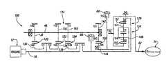
- FIG. 1is a schematic representation of a powertrain having a power transmission incorporating one embodiment of the present invention.
- FIG. 2is a table describing the engagement sequence of the torque-transmitting mechanisms and the gear ratios that are available as well as the step ratios between forward speed ratios.
- FIG. 3is a schematic representation of a powertrain similar to that shown in FIG. 1 incorporating another embodiment of the present invention.
- FIG. 4is a table similar to FIG. 2 describing the engagement sequence of the torque-transmitting mechanisms as well as gear ratios and step ratios for the transmission shown in FIG. 3 .
- FIG. 5is a schematic representation of a powertrain having a power transmission incorporating another embodiment of the present invention.
- FIG. 6is a table similar to FIGS. 2 and 4 describing the engagement sequence of the torque-transmitting mechanisms as well as the gear ratios and step ratios provided thereby.
- FIG. 1a powertrain 10 including a conventional internal combustion engine and manual clutch 12 , a multi-speed power transmission 14 , and a conventional differential mechanism 16 .
- the transmission 14has an input shaft 18 connected with the engine and clutch 12 , three ratio gearsets 20 , 22 , and 24 , an output gearset 26 , and a planetary gearset 28 .
- the ratio gearset 20has an input gear 30 and an output gear 32 .
- the ratio gearset 22has an input gear or ratio gear 34 and an output gear or ratio gear 36 .
- the ratio gearset 24has an input gear or ratio gear 38 and an output gear or ratio gear 40 .
- the output gearset 26has an input gear or ratio gear 42 and an output gear or ratio gear 44 .
- the input gears 30 , 34 , and 38are rotatably supported on the input shaft 18 and the output gear 44 is rotatably mounted on a transfer shaft 46 .
- the synchronizer torque-transmitting mechanism C 1is selectively engageable to connect the input gear 30 with the input shaft 18
- the synchronizer torque-transmitting mechanism C 2is operable to connect the input shaft 18 with the input gear 34
- the synchronizer torque-transmitting mechanism C 3is operable to connect the input shaft 18 with the input gear 38
- the synchronizer torque-transmitting mechanism C 4is operable to connect the input shaft 18 with the transfer shaft 46 .
- the output gears 32 , 36 , and 40 and the input gear 42are fixedly secured with a countershaft 48 .
- the planetary gearset 28includes a sun gear member 50 , a ring gear member 52 , and a planet carrier assembly member 54 , which includes a plurality of pinion gears 56 rotatably mounted on a planet carrier member 58 .
- the planet carrier member 58is continuously connected with the transfer shaft 46 , such that engagement of the synchronizer torque-transmitting mechanism C 4 provides a drive connection between the input shaft 18 and the planet carrier member 58 .
- the sun gear member 50is selectively connected with a stationary component or housing 60 through a torque-transmitting mechanism SG.
- the planet carrier member 58is selectively connectible with the housing 60 through a selectively engageable torque-transmitting mechanism CG and selectively connectible with the ring gear member 52 to a selectively engageable torque-transmitting mechanism PL.
- the ring gear member 52is continuously connected with an output shaft 62 , which is continuously drivingly connected with the differential 16 .
- a park device RGis provided, which will connect the ring gear member 52 and therefore the output shaft 62 with the stationary member 60 when it is desired to hold the vehicle stationary.
- the synchronizer torque-transmitting mechanisms C 1 and C 2may be one-way synchronizers or two-way synchronizers, both of which are conventional devices.
- the synchronizer torque-transmitting mechanisms C 3 and C 4may both be one-way synchronizers, which are conventional, or may be constructed in accordance with the more sophisticated devices shown U.S. Ser. No. 10/717,320, filed Nov. 19, 2003, and assigned to the assignee of the present invention.
- the devices shown in that patent applicationare three-way and four-way synchronizers, which would permit separate engagement of C 3 and C 4 as well as joint engagement of C 3 and C 4 .
- the selective engagement of the synchronizer torque-transmitting mechanisms C 1 , C 2 , C 3 , and C 4 , and the planetary controlled torque-transmitting mechanisms SG, CG, and PLare employed in combinations of two to establish eight forward speed ratios and three reverse speed ratios between the input shaft 18 and the output shaft 62 .
- the first and lowest reverse speed ratiois established with the engagement of the synchronizer torque-transmitting mechanism C 1 and the torque-transmitting mechanism CG.
- the countershaft 48With the engagement of the synchronizer torque-transmitting mechanism C 1 , the countershaft 48 is rotated at a speed determined by the ratio between the ratio gears 30 , 32 , the sun gear member 50 is rotated at a speed determined by the ratio between the output gears 42 and 44 .
- the planetary gearset 28establishes a reverse speed ratio with the engagement of the synchronizer torque-transmitting mechanism CG thereby holding the planet carrier member 58 stationary.
- the ring gear member 52 and the output shaft 62are rotated in the reverse direction, that is, the direction opposite to the rotation of the input shaft 18 .
- the second reverse speed ratio R 2is established with the engagement of the synchronizer torque-transmitting mechanism C 2 and simultaneous release of the synchronizer torque-transmitting mechanism C 1 , such that the input shaft speed is transferred to the countershaft 48 through the ratio gears 34 and 36 and then through the output gear set 26 and the planetary gearset 28 in a manner similar to first reverse speed ratio.
- the third reverse speed ratio R 3is established with the simultaneous disengagement of the synchronizer torque-transmitting mechanism C 2 and the engagement of the synchronizer torque-transmitting mechanism C 3 , thereby creating a ratio between the input shaft 18 and the countershaft 48 , which is determined by the ratio of the gears 38 and 40 .
- the output of the countershaft 48is the same for the third reverse speed ratio as it is for the first and second reverse speed ratio.
- the engagement sequence and ratio valuesare given in FIG. 2 . These ratio values are determined numerically by the ratio numbers of the various gear components. As an example only, the ratio between the gears 30 and 32 is 1.82, that is, the gear 30 will rotate 1.82 times faster than the gear 32 . The ratio between the gears 34 and 36 is 1.15, and the ratio between the gears 38 and 40 is 0.75. The ratio between the gears 42 and 44 is 1.85, that is, the gear 42 will rotate 1.85 times as fast as the gear 44 .
- the ring gear/sun gear ratio of the planetary gearset 28is 1.61, which will establish the ratios within the planetary gearset depending upon the torque-transmitting mechanism engaged.
- the ratio numbers given in FIG. 2for example R 1 , which is equal to ⁇ 5.428, signifies that the input shaft 18 will rotate 5.428 times for each rotation of the output shaft 62 . All three of the reverse speed ratios are therefore underdrive ratios, meaning that the output rotates at a slower speed than the input.
- the first forward speed ratiois established with the engagement of the torque-transmitting mechanism PL and the synchronizer torque-transmitting mechanism C 1 .
- the torque-transmitting mechanism PLputs the planetary gearset 28 in a 1:1 condition, and therefore the ratio between the input shaft 18 and the output shaft 62 is determined by the ratio of the gearset 20 and the gearset 26 .
- the second forward speed ratiois determined by interchanging the synchronizer torque transmitting mechanisms C 1 , C 2 , thereby changing the ratio between the input shaft 18 and the countershaft 48 , such that the second forward speed ratio is determined by the ratios of the gearsets 22 and 26 .
- the third forward speed ratiois established with the simultaneous interchange of the synchronizer torque-transmitting mechanisms C 3 and C 2 , such that the third forward speed ratio is determined by the ratio of the gearsets 24 and 26 .
- Each of the interchanges of the synchronizer torque-transmitting mechanisms C 1 , C 2 , C 3 , and C 4is accompanied by the engagement and disengagement of the clutch portion of the engine and clutch 12 .
- the clutch combined with the engine 12is a conventional friction clutch mechanism that may be manually or automatically operated.
- the fourth forward speed ratiois established with the interchange of the synchronizer torque-transmitting mechanisms C 3 and C 4 , which provides a direct connection between the input shaft 18 and the output shaft 62 .
- the fifth forward speed ratiois established with the simultaneous engagement of the synchronizer torque-transmitting mechanisms C 3 and C 4 , and the disengagement of the torque-transmitting mechanism PL.
- the countershaft 48 and therefore the sun gear member 50is rotated at a speed determined by the ratios of the gearsets 24 and 26 .
- the planet carrier member 58is rotated at the speed of the input shaft 18 , thereby producing an overdrive ratio within the planetary gearset 28 , such that the ring gear member 52 and therefore the output shaft 62 will rotate at a speed greater than the speed of the input shaft 18 .
- the sixth forward speed ratiois established with the engagement of the synchronizer torque-transmitting mechanisms C 4 and C 2 .
- the synchronizer torque-transmitting mechanisms C 3 and C 2are interchanged during this ratio shift.
- the engagement of the synchronizer torque-transmitting mechanism C 2 and therefore the ratio of the gearset 22provide for the countershaft 48 to rotate at a slower speed than that established by engagement of the synchronizer torque-transmitting mechanism C 3 .
- the sun gear member 50will rotate forward at a slower speed while the planet carrier member 58 remains rotating at the speed of the input shaft 18 , thus resulting in a higher output speed due to the overdrive ratio that is established within the planetary gearset 28 .
- the seventh forward speed ratiois established with the engagement of the synchronizer torque-transmitting mechanism C 4 and the interchange of the synchronizer torque-transmitting mechanisms C 2 , C 1 , resulting in a slower rotation of the countershaft 48 and therefore a higher overdrive at the output shaft 62 .
- the eighth forward speed ratiois established by the disengagement of the synchronizer torque-transmitting mechanism C 1 and the simultaneous engagement of the torque-transmitting mechanism SG.
- the torque-transmitting mechanism SGwill hold the sun gear member 50 stationary while the planet carrier member 58 is driven directly by the input shaft 18 resulting in even more overdrive ratio at the output shaft 62 .
- the steps between adjacent forward speed ratiosare also shown in FIG. 2.
- the step between first and second forwardis 1.58.
- the step ratios between some of the overdrive ratiosfor example, between forward sixth speed and forward seventh speed, is only 1.08.
- the fifth forward speed ratio and seventh forward speed ratiocan be skipped, such that the step ratio between fourth and sixth will be 1.33 and the step between sixth and eighth would be 1.22.
- Controls to provide thisare well known in the art.
- the operatorif manually controlling the synchronizer torque transmitting mechanisms, can do a skip shift when only a synchronizer interchange is involved as exists during the first through seventh speeds. Automatic skip shifting is also possible.
- a powertrain 100is shown in FIG. 3 .
- the powertrain 100includes the engine and clutch 12 , the differential output 16 and a multi-speed transmission 114 .
- the multi-speed transmissionincludes three ratio gearsets 120 , 122 , and 124 , and an output gearset 126 .
- Also included within the multi-speed transmission 114is a planetary gearset 128 , which includes a sun gear member 150 , a ring gear member 152 , a planet carrier assembly member 154 , which has a plurality of pairs of meshing pinion gears 156 and 157 , which are rotatably mounted on a planet carrier member 158 and disposed in meshing relationship with the sun gear member 150 and the ring gear member 152 , respectively.
- the planetary gearset 128is known as a double-pinion or compound-pinion planetary gearset. With these types of planetary gears, the sun gear member and ring gear member will rotate in the same direction when the carrier is held stationary. If the ring gear member is held stationary and the planet carrier is rotated, the sun gear member will rotate in a direction opposite to the rotation of the carrier.
- the sun gear member 150is continuously connected with the transmission output shaft 62 .
- the ring gear member 152is connected with the synchronizer torque-transmitting mechanism C 4 and with a selectively engageable torque-transmitting mechanism RG, which is connected with the transmission housing 60 .
- the torque-transmitting mechanism RGis therefore a stationary-type torque-transmitting mechanism, commonly termed a brake.
- the planet carrier member 158is selectively engageable with the housing 60 through the torque-transmitting mechanism CG and selectively interconnectible with the sun gear member 150 through a conventional selectively engageable torque-transmitting mechanism PL. A further connection with the planet carrier member 158 is through the output gearset 126 .
- the ratio gearset 120includes the meshing gears 130 and 132
- the ratio gearset 122includes the meshing gears 134 and 136
- the ratio gearset 124includes the meshing gears 138 and 140
- the output gearset 126includes the meshing gears 142 and 144 .
- the synchronizer torque-transmitting mechanisms C 1 , C 2 , and C 3are effective to connect the input shaft 18 to the countershaft 48 .
- the major difference between the transmission shown in FIG. 1 and that shown in FIG. 3is the arrangement of the planetary gearset 128 .
- the table of FIG. 4describes the engagement sequence of the torque-transmitting mechanisms C 1 , C 2 , C 3 , C 4 , RG, CG, and P 1 .
- the ratio between the gears 130 and 132is 1.9, the ratio between the gears 134 and 136 is 1.15, the ratio between the gears 138 and 140 is 0.75, and the ratio between the gears 142 and 144 is 1.85. These numbers, of course, are given by way of example only.
- the ring gear/sun gear ratio for the planetary gearset 128is 2.00.
- step ratios between adjacent forward speed ratiosare sequenced differently than those of FIG. 1 , which is a result of choosing different gear ratios within the countershaft portion of the transmission and the planetary portion of the transmission.
- first reverse speed ratio and the first forward speed ratioare equal. This is desirable in some transmissions depending upon the vehicle in which the transmission is installed.
- a powertrain 210is shown in FIG. 5 .
- the powertrain 210includes the engine and clutch 12 , the output differential 16 , and a multi-speed transmission 214 .
- the multi-speed transmission 214includes a countershaft section having three ratio gearsets 220 , 222 , and 224 and an output gearset 226 .
- the transmission 214also includes a double-pinion planetary gearset 228 , which is similar in construction to the planetary gearset 128 with the exception that a planet carrier 258 is continuously connected with the output shaft 62 , a ring gear member 252 is connected with the synchronizer torque-transmitting mechanism C 4 , and a sun gear member 250 is connected with the output gearset 226 .
- the ratio gearset 220is controlled by the synchronizer torque-transmitting mechanism C 1 .
- the ratio gearset 222is controlled by the synchronizer torque-transmitting mechanism C 2 .
- the ratio gearset 224is controlled by the synchronizer torque-transmitting mechanism C 3 .
- Each of these torque-transmitting mechanismsis effective to connect their respective ratio gearsets with the input shaft 18 .
- the planetary gearset 228includes the sun gear member 250 , the ring gear member 252 , and the planet carrier assembly member 254 , which has incorporated therein a plurality of pairs of meshing pinion gears 256 and 257 rotatably supported on a planet carrier member 258 .
- the planet carrier member 258is connected continuously with the output shaft 62 and is selectively connectible with the sun gear member 250 through the selectively engageable torque-transmitting mechanism PL.
- the sun gear member 250is also selectively connectible with the transmission housing 60 .
- the ring gear member 252is selectively connected with the transmission housing 60 through the torque-transmitting mechanism RG, and, as previously mentioned, with the synchronizer torque-transmitting mechanism C 4 .
- the gear ratio between gears 230 and 232is 1.50, the gear ratio between gears 234 and 236 is 0.981, and the gear ratio between gears 238 and 240 is 0.666.
- the gear ratio between gears 242 and 244is 2.0 and the ring gear/sun gear ratio of the planetary gearset 228 is 2.19. As mentioned above, these numbers are given by way of example and are not considered limiting for this invention.
- the table of FIG. 6describes the engagement of the torque-transmitting mechanisms and the ratios, which are established thereby with the given gear ratio numbers.
- FIG. 6also describes the step ratio between adjacent forward speed ratios.
- the countershaft 48increases in speed with the progression of the first three forward speed ratios.
- the countershaft 48is not included in the fourth forward speed ratio, which is a direct drive, and the countershaft 48 is decreased in speed during the establishment of the ratios five, six, and seven.
- the countershaftis held stationary during the eighth forward speed ratio, which is the highest overdrive ratio.
- the planetary gearsets of the transmissions describedis rotated as a single unit, thereby reducing the spin and gear losses occasioned with the planetary action.
- the ratio changesare simple in that during the first four forward speed ratios the ratio changes are all made with the planetary gearset in a 1:1 condition, and the fifth through eighth speed ratios are all made with the synchronizer torque-transmitting mechanism C 4 engaged and the planetary gearset providing a combiner.
- Thispermits synchronizer interchanges for the first through fourth speeds and also synchronizer interchanges for fifth through seventh and a synchronizer-to-friction device change for eighth forward speed.
- the synchronizersare stepped from C 1 to C 4
- the synchronizersare stepped from C 3 to C 1 .
Landscapes
- Engineering & Computer Science (AREA)
- General Engineering & Computer Science (AREA)
- Mechanical Engineering (AREA)
- Structure Of Transmissions (AREA)
Abstract
Description
Claims (5)
Priority Applications (1)
| Application Number | Priority Date | Filing Date | Title |
|---|---|---|---|
| US10/951,421US7104917B2 (en) | 2004-09-28 | 2004-09-28 | Countershaft planetary transmissions |
Applications Claiming Priority (1)
| Application Number | Priority Date | Filing Date | Title |
|---|---|---|---|
| US10/951,421US7104917B2 (en) | 2004-09-28 | 2004-09-28 | Countershaft planetary transmissions |
Publications (2)
| Publication Number | Publication Date |
|---|---|
| US20060068964A1 US20060068964A1 (en) | 2006-03-30 |
| US7104917B2true US7104917B2 (en) | 2006-09-12 |
Family
ID=36100009
Family Applications (1)
| Application Number | Title | Priority Date | Filing Date |
|---|---|---|---|
| US10/951,421Expired - LifetimeUS7104917B2 (en) | 2004-09-28 | 2004-09-28 | Countershaft planetary transmissions |
Country Status (1)
| Country | Link |
|---|---|
| US (1) | US7104917B2 (en) |
Cited By (22)
| Publication number | Priority date | Publication date | Assignee | Title |
|---|---|---|---|---|
| US20070234834A1 (en)* | 2004-09-23 | 2007-10-11 | Carsten Gitt | Automated motor vehicle transmission and method of operating the same |
| US20120122623A1 (en)* | 2008-07-30 | 2012-05-17 | Rodgers Ii Dane L | Gear assembly for multi-speed countershaft transmission |
| US8483919B2 (en) | 2010-11-12 | 2013-07-09 | Allison Transmission, Inc. | Double transition shift control in an automatic powershifting transmission |
| US8986150B2 (en) | 2012-09-07 | 2015-03-24 | Dana Limited | Ball type continuously variable transmission/infinitely variable transmission |
| US9052000B2 (en) | 2012-09-07 | 2015-06-09 | Dana Limited | Ball type CVT/IVT including planetary gear sets |
| US9194472B2 (en) | 2013-03-14 | 2015-11-24 | Dana Limited | Ball type continuously variable transmission |
| US9347532B2 (en) | 2012-01-19 | 2016-05-24 | Dana Limited | Tilting ball variator continuously variable transmission torque vectoring device |
| US9353842B2 (en) | 2012-09-07 | 2016-05-31 | Dana Limited | Ball type CVT with powersplit paths |
| US9404414B2 (en) | 2013-02-08 | 2016-08-02 | Dana Limited | Internal combustion engine coupled turbocharger with an infinitely variable transmission |
| US9541179B2 (en) | 2012-02-15 | 2017-01-10 | Dana Limited | Transmission and driveline having a tilting ball variator continuously variable transmission |
| US9551404B2 (en) | 2013-03-14 | 2017-01-24 | Dana Limited | Continuously variable transmission and an infinitely variable transmission variator drive |
| US9556943B2 (en) | 2012-09-07 | 2017-01-31 | Dana Limited | IVT based on a ball-type CVP including powersplit paths |
| US9556941B2 (en) | 2012-09-06 | 2017-01-31 | Dana Limited | Transmission having a continuously or infinitely variable variator drive |
| US9599204B2 (en) | 2012-09-07 | 2017-03-21 | Dana Limited | Ball type CVT with output coupled powerpaths |
| US9638296B2 (en) | 2012-09-07 | 2017-05-02 | Dana Limited | Ball type CVT including a direct drive mode |
| DE102015226208A1 (en)* | 2015-12-21 | 2017-06-22 | Zf Friedrichshafen Ag | Manual transmission and method for its operation |
| US9777815B2 (en) | 2013-06-06 | 2017-10-03 | Dana Limited | 3-mode front wheel drive and rear wheel drive continuously variable planetary transmission |
| US10006529B2 (en) | 2014-06-17 | 2018-06-26 | Dana Limited | Off-highway continuously variable planetary-based multimode transmission including infinite variable transmission and direct continuously variable transmission |
| US10030748B2 (en) | 2012-11-17 | 2018-07-24 | Dana Limited | Continuously variable transmission |
| US10030751B2 (en) | 2013-11-18 | 2018-07-24 | Dana Limited | Infinite variable transmission with planetary gear set |
| US10030594B2 (en) | 2015-09-18 | 2018-07-24 | Dana Limited | Abuse mode torque limiting control method for a ball-type continuously variable transmission |
| US10088022B2 (en) | 2013-11-18 | 2018-10-02 | Dana Limited | Torque peak detection and control mechanism for a CVP |
Families Citing this family (2)
| Publication number | Priority date | Publication date | Assignee | Title |
|---|---|---|---|---|
| US7789788B2 (en)* | 2006-10-09 | 2010-09-07 | Gm Global Technology Operations, Inc. | Multi-speed transmission |
| FR2912693B1 (en)* | 2007-02-21 | 2009-08-28 | Renault Soc Par Actions Simpli | MODE CHANGE DEVICE FOR POWER DERIVATION TRANSMISSION. |
Citations (6)
| Publication number | Priority date | Publication date | Assignee | Title |
|---|---|---|---|---|
| JPH02225844A (en)* | 1989-02-23 | 1990-09-07 | Toyota Motor Corp | Manual transmission |
| US5310390A (en)* | 1990-09-28 | 1994-05-10 | Jatco Corporation | Automatic transmission |
| US5823051A (en)* | 1997-05-05 | 1998-10-20 | General Motors Corporation | Multi-speed power transmission |
| US5971883A (en)* | 1998-03-13 | 1999-10-26 | General Motors Corporation | Multi-speed power transmission |
| US6066062A (en)* | 1997-11-12 | 2000-05-23 | Iveco Fiat S.P.A. | Gear change for automobile vehicle provided with auxiliary epicyclic gear train with helical gears including axially displaceable crown |
| US20030040388A1 (en)* | 2001-07-31 | 2003-02-27 | Toyota Jidosha Kabushiki Kaisha | Apparatus for controlling vehicle automatic transmission |
- 2004
- 2004-09-28USUS10/951,421patent/US7104917B2/ennot_activeExpired - Lifetime
Patent Citations (6)
| Publication number | Priority date | Publication date | Assignee | Title |
|---|---|---|---|---|
| JPH02225844A (en)* | 1989-02-23 | 1990-09-07 | Toyota Motor Corp | Manual transmission |
| US5310390A (en)* | 1990-09-28 | 1994-05-10 | Jatco Corporation | Automatic transmission |
| US5823051A (en)* | 1997-05-05 | 1998-10-20 | General Motors Corporation | Multi-speed power transmission |
| US6066062A (en)* | 1997-11-12 | 2000-05-23 | Iveco Fiat S.P.A. | Gear change for automobile vehicle provided with auxiliary epicyclic gear train with helical gears including axially displaceable crown |
| US5971883A (en)* | 1998-03-13 | 1999-10-26 | General Motors Corporation | Multi-speed power transmission |
| US20030040388A1 (en)* | 2001-07-31 | 2003-02-27 | Toyota Jidosha Kabushiki Kaisha | Apparatus for controlling vehicle automatic transmission |
Cited By (34)
| Publication number | Priority date | Publication date | Assignee | Title |
|---|---|---|---|---|
| US7731617B2 (en)* | 2004-09-23 | 2010-06-08 | Daimler A.G. | Automated motor vehicle transmission and method of operating the same |
| US20070234834A1 (en)* | 2004-09-23 | 2007-10-11 | Carsten Gitt | Automated motor vehicle transmission and method of operating the same |
| US20120122623A1 (en)* | 2008-07-30 | 2012-05-17 | Rodgers Ii Dane L | Gear assembly for multi-speed countershaft transmission |
| US8827858B2 (en)* | 2008-07-30 | 2014-09-09 | Allison Transmission, Inc. | Gear assembly for multi-speed countershaft transmission |
| US8483919B2 (en) | 2010-11-12 | 2013-07-09 | Allison Transmission, Inc. | Double transition shift control in an automatic powershifting transmission |
| US8718886B2 (en) | 2010-11-12 | 2014-05-06 | Allison Transmission, Inc. | Double transition shift control in an automatic powershifting transmission |
| US9169921B2 (en) | 2010-11-12 | 2015-10-27 | Allison Transmission, Inc. | Double transition shift control in an automatic powershifting transmission |
| US9347532B2 (en) | 2012-01-19 | 2016-05-24 | Dana Limited | Tilting ball variator continuously variable transmission torque vectoring device |
| US9541179B2 (en) | 2012-02-15 | 2017-01-10 | Dana Limited | Transmission and driveline having a tilting ball variator continuously variable transmission |
| US9556941B2 (en) | 2012-09-06 | 2017-01-31 | Dana Limited | Transmission having a continuously or infinitely variable variator drive |
| US9556943B2 (en) | 2012-09-07 | 2017-01-31 | Dana Limited | IVT based on a ball-type CVP including powersplit paths |
| US9353842B2 (en) | 2012-09-07 | 2016-05-31 | Dana Limited | Ball type CVT with powersplit paths |
| US10088026B2 (en) | 2012-09-07 | 2018-10-02 | Dana Limited | Ball type CVT with output coupled powerpaths |
| US9416858B2 (en) | 2012-09-07 | 2016-08-16 | Dana Limited | Ball type continuously variable transmission/infinitely variable transmission |
| US10006527B2 (en) | 2012-09-07 | 2018-06-26 | Dana Limited | Ball type continuously variable transmission/infinitely variable transmission |
| US9052000B2 (en) | 2012-09-07 | 2015-06-09 | Dana Limited | Ball type CVT/IVT including planetary gear sets |
| US8986150B2 (en) | 2012-09-07 | 2015-03-24 | Dana Limited | Ball type continuously variable transmission/infinitely variable transmission |
| US9599204B2 (en) | 2012-09-07 | 2017-03-21 | Dana Limited | Ball type CVT with output coupled powerpaths |
| US9638296B2 (en) | 2012-09-07 | 2017-05-02 | Dana Limited | Ball type CVT including a direct drive mode |
| US9689477B2 (en) | 2012-09-07 | 2017-06-27 | Dana Limited | Ball type continuously variable transmission/infinitely variable transmission |
| US10030748B2 (en) | 2012-11-17 | 2018-07-24 | Dana Limited | Continuously variable transmission |
| US9644530B2 (en) | 2013-02-08 | 2017-05-09 | Dana Limited | Internal combustion engine coupled turbocharger with an infinitely variable transmission |
| US9404414B2 (en) | 2013-02-08 | 2016-08-02 | Dana Limited | Internal combustion engine coupled turbocharger with an infinitely variable transmission |
| US9689482B2 (en) | 2013-03-14 | 2017-06-27 | Dana Limited | Ball type continuously variable transmission |
| US9638301B2 (en) | 2013-03-14 | 2017-05-02 | Dana Limited | Ball type continuously variable transmission |
| US9933054B2 (en) | 2013-03-14 | 2018-04-03 | Dana Limited | Continuously variable transmission and an infinitely variable transmission variator drive |
| US9551404B2 (en) | 2013-03-14 | 2017-01-24 | Dana Limited | Continuously variable transmission and an infinitely variable transmission variator drive |
| US9194472B2 (en) | 2013-03-14 | 2015-11-24 | Dana Limited | Ball type continuously variable transmission |
| US9777815B2 (en) | 2013-06-06 | 2017-10-03 | Dana Limited | 3-mode front wheel drive and rear wheel drive continuously variable planetary transmission |
| US10030751B2 (en) | 2013-11-18 | 2018-07-24 | Dana Limited | Infinite variable transmission with planetary gear set |
| US10088022B2 (en) | 2013-11-18 | 2018-10-02 | Dana Limited | Torque peak detection and control mechanism for a CVP |
| US10006529B2 (en) | 2014-06-17 | 2018-06-26 | Dana Limited | Off-highway continuously variable planetary-based multimode transmission including infinite variable transmission and direct continuously variable transmission |
| US10030594B2 (en) | 2015-09-18 | 2018-07-24 | Dana Limited | Abuse mode torque limiting control method for a ball-type continuously variable transmission |
| DE102015226208A1 (en)* | 2015-12-21 | 2017-06-22 | Zf Friedrichshafen Ag | Manual transmission and method for its operation |
Also Published As
| Publication number | Publication date |
|---|---|
| US20060068964A1 (en) | 2006-03-30 |
Similar Documents
| Publication | Publication Date | Title |
|---|---|---|
| US7104917B2 (en) | Countershaft planetary transmissions | |
| US6932735B2 (en) | Six-speed planetary transmission mechanisms with two clutches and three brakes | |
| US7247119B2 (en) | Multi-speed planetary power transmission | |
| US7695390B2 (en) | Multi-speed transmission | |
| EP1387112A2 (en) | Family of multi-speed transmission mechanisms with three input clutches and three planetary gearsets | |
| US6705967B2 (en) | Six-speed transmission with three planetary gear sets and five torque transmitting mechanisms | |
| US7353724B2 (en) | Multi-speed transmission with Hi-Lo output torque-transmitting mechanisms and gear sets | |
| US8083632B2 (en) | Eight-speed transmission | |
| US6736750B1 (en) | Family of multi-speed planetary transmission mechanisms having clutch input | |
| US6626789B2 (en) | Family of six-speed transmission mechanisms with three planetary gearsets | |
| US6716131B1 (en) | Family of multi-speed power transmissions with three gearsets | |
| US6595892B2 (en) | Multi-speed transmission family with three planetary gear sets and five rotating torque transmitting mechanisms | |
| US6589129B2 (en) | Powertrain having a multi-speed transmission with three planetary gear sets | |
| US20040087410A1 (en) | Family of multi-speed planetary transmissions having a clutched input and one stationary member | |
| US20030203787A1 (en) | Multi-speed planetary transmissions with clutched input and three planetary gearsets | |
| US6976933B2 (en) | Multi-speed power transmission | |
| US6758785B2 (en) | Multi-speed transmission with three planetary gearsets and input clutches | |
| KR20030055543A (en) | Method of controlling 6 - shift in an automatic transmission for vehicles | |
| US6773371B2 (en) | Family of multi-speed transmissions having interconnected planetary gearsets and input clutches | |
| US6712732B1 (en) | Family of multi-speed planetary transmissions each having two input clutches and three planetary gearsets | |
| EP1416192B1 (en) | Family of multi-speed planetary transmissions with a stationary planetary member and input clutches | |
| US20040082429A1 (en) | Multi-speed transmission mechanisms with three planetary gearsets and clutch input |
Legal Events
| Date | Code | Title | Description |
|---|---|---|---|
| AS | Assignment | Owner name:GENERAL MOTORS CORPORATION, MICHIGAN Free format text:ASSIGNMENT OF ASSIGNORS INTEREST;ASSIGNORS:KLEMEN, DONALD;HALL, ARTHUR, III;REEL/FRAME:015482/0812 Effective date:20040817 | |
| STCF | Information on status: patent grant | Free format text:PATENTED CASE | |
| AS | Assignment | Owner name:GM GLOBAL TECHNOLOGY OPERATIONS, INC., MICHIGAN Free format text:ASSIGNMENT OF ASSIGNORS INTEREST;ASSIGNOR:GENERAL MOTORS CORPORATION;REEL/FRAME:022117/0022 Effective date:20050119 Owner name:GM GLOBAL TECHNOLOGY OPERATIONS, INC.,MICHIGAN Free format text:ASSIGNMENT OF ASSIGNORS INTEREST;ASSIGNOR:GENERAL MOTORS CORPORATION;REEL/FRAME:022117/0022 Effective date:20050119 | |
| AS | Assignment | Owner name:UNITED STATES DEPARTMENT OF THE TREASURY, DISTRICT Free format text:SECURITY AGREEMENT;ASSIGNOR:GM GLOBAL TECHNOLOGY OPERATIONS, INC.;REEL/FRAME:022201/0610 Effective date:20081231 Owner name:UNITED STATES DEPARTMENT OF THE TREASURY,DISTRICT Free format text:SECURITY AGREEMENT;ASSIGNOR:GM GLOBAL TECHNOLOGY OPERATIONS, INC.;REEL/FRAME:022201/0610 Effective date:20081231 | |
| AS | Assignment | Owner name:CITICORP USA, INC. AS AGENT FOR BANK PRIORITY SECU Free format text:SECURITY AGREEMENT;ASSIGNOR:GM GLOBAL TECHNOLOGY OPERATIONS, INC.;REEL/FRAME:022553/0446 Effective date:20090409 Owner name:CITICORP USA, INC. AS AGENT FOR HEDGE PRIORITY SEC Free format text:SECURITY AGREEMENT;ASSIGNOR:GM GLOBAL TECHNOLOGY OPERATIONS, INC.;REEL/FRAME:022553/0446 Effective date:20090409 | |
| AS | Assignment | Owner name:GM GLOBAL TECHNOLOGY OPERATIONS, INC., MICHIGAN Free format text:RELEASE BY SECURED PARTY;ASSIGNOR:UNITED STATES DEPARTMENT OF THE TREASURY;REEL/FRAME:023124/0429 Effective date:20090709 Owner name:GM GLOBAL TECHNOLOGY OPERATIONS, INC.,MICHIGAN Free format text:RELEASE BY SECURED PARTY;ASSIGNOR:UNITED STATES DEPARTMENT OF THE TREASURY;REEL/FRAME:023124/0429 Effective date:20090709 | |
| AS | Assignment | Owner name:GM GLOBAL TECHNOLOGY OPERATIONS, INC., MICHIGAN Free format text:RELEASE BY SECURED PARTY;ASSIGNORS:CITICORP USA, INC. AS AGENT FOR BANK PRIORITY SECURED PARTIES;CITICORP USA, INC. AS AGENT FOR HEDGE PRIORITY SECURED PARTIES;REEL/FRAME:023127/0468 Effective date:20090814 Owner name:GM GLOBAL TECHNOLOGY OPERATIONS, INC.,MICHIGAN Free format text:RELEASE BY SECURED PARTY;ASSIGNORS:CITICORP USA, INC. AS AGENT FOR BANK PRIORITY SECURED PARTIES;CITICORP USA, INC. AS AGENT FOR HEDGE PRIORITY SECURED PARTIES;REEL/FRAME:023127/0468 Effective date:20090814 | |
| AS | Assignment | Owner name:UNITED STATES DEPARTMENT OF THE TREASURY, DISTRICT Free format text:SECURITY AGREEMENT;ASSIGNOR:GM GLOBAL TECHNOLOGY OPERATIONS, INC.;REEL/FRAME:023156/0052 Effective date:20090710 Owner name:UNITED STATES DEPARTMENT OF THE TREASURY,DISTRICT Free format text:SECURITY AGREEMENT;ASSIGNOR:GM GLOBAL TECHNOLOGY OPERATIONS, INC.;REEL/FRAME:023156/0052 Effective date:20090710 | |
| AS | Assignment | Owner name:UAW RETIREE MEDICAL BENEFITS TRUST, MICHIGAN Free format text:SECURITY AGREEMENT;ASSIGNOR:GM GLOBAL TECHNOLOGY OPERATIONS, INC.;REEL/FRAME:023162/0001 Effective date:20090710 Owner name:UAW RETIREE MEDICAL BENEFITS TRUST,MICHIGAN Free format text:SECURITY AGREEMENT;ASSIGNOR:GM GLOBAL TECHNOLOGY OPERATIONS, INC.;REEL/FRAME:023162/0001 Effective date:20090710 | |
| FPAY | Fee payment | Year of fee payment:4 | |
| AS | Assignment | Owner name:GM GLOBAL TECHNOLOGY OPERATIONS, INC., MICHIGAN Free format text:RELEASE BY SECURED PARTY;ASSIGNOR:UAW RETIREE MEDICAL BENEFITS TRUST;REEL/FRAME:025311/0770 Effective date:20101026 Owner name:GM GLOBAL TECHNOLOGY OPERATIONS, INC., MICHIGAN Free format text:RELEASE BY SECURED PARTY;ASSIGNOR:UNITED STATES DEPARTMENT OF THE TREASURY;REEL/FRAME:025245/0442 Effective date:20100420 | |
| AS | Assignment | Owner name:WILMINGTON TRUST COMPANY, DELAWARE Free format text:SECURITY AGREEMENT;ASSIGNOR:GM GLOBAL TECHNOLOGY OPERATIONS, INC.;REEL/FRAME:025327/0001 Effective date:20101027 | |
| AS | Assignment | Owner name:GM GLOBAL TECHNOLOGY OPERATIONS LLC, MICHIGAN Free format text:CHANGE OF NAME;ASSIGNOR:GM GLOBAL TECHNOLOGY OPERATIONS, INC.;REEL/FRAME:025780/0936 Effective date:20101202 | |
| FPAY | Fee payment | Year of fee payment:8 | |
| AS | Assignment | Owner name:GM GLOBAL TECHNOLOGY OPERATIONS LLC, MICHIGAN Free format text:RELEASE BY SECURED PARTY;ASSIGNOR:WILMINGTON TRUST COMPANY;REEL/FRAME:034371/0676 Effective date:20141017 | |
| MAFP | Maintenance fee payment | Free format text:PAYMENT OF MAINTENANCE FEE, 12TH YEAR, LARGE ENTITY (ORIGINAL EVENT CODE: M1553) Year of fee payment:12 |