US7104719B2 - Peripheral connecting region of two sheets and peripheral connection method - Google Patents
Peripheral connecting region of two sheets and peripheral connection methodDownload PDFInfo
- Publication number
- US7104719B2 US7104719B2US10/428,004US42800403AUS7104719B2US 7104719 B2US7104719 B2US 7104719B2US 42800403 AUS42800403 AUS 42800403AUS 7104719 B2US7104719 B2US 7104719B2
- Authority
- US
- United States
- Prior art keywords
- flanges
- fastening element
- region
- sheets
- peripheral
- Prior art date
- Legal status (The legal status is an assumption and is not a legal conclusion. Google has not performed a legal analysis and makes no representation as to the accuracy of the status listed.)
- Expired - Fee Related, expires
Links
- 230000002093peripheral effectEffects0.000titleclaimsabstractdescription44
- 238000000034methodMethods0.000titledescription16
- 230000000284resting effectEffects0.000claimsdescription5
- 230000001154acute effectEffects0.000claimsdescription4
- 238000004519manufacturing processMethods0.000abstractdescription2
- 239000000463materialSubstances0.000description13
- 238000003466weldingMethods0.000description11
- 229910000831SteelInorganic materials0.000description5
- 239000010959steelSubstances0.000description5
- 239000000853adhesiveSubstances0.000description4
- 230000001070adhesive effectEffects0.000description4
- XAGFODPZIPBFFR-UHFFFAOYSA-NaluminiumChemical compound[Al]XAGFODPZIPBFFR-UHFFFAOYSA-N0.000description2
- 229910052782aluminiumInorganic materials0.000description2
- 239000004411aluminiumSubstances0.000description2
- 238000006073displacement reactionMethods0.000description2
- 238000005304joiningMethods0.000description2
- 229920003023plasticPolymers0.000description2
- 239000004033plasticSubstances0.000description2
- 230000001419dependent effectEffects0.000description1
- 230000000694effectsEffects0.000description1
- 238000012986modificationMethods0.000description1
- 230000004048modificationEffects0.000description1
- 239000000126substanceSubstances0.000description1
Images


Classifications
- F—MECHANICAL ENGINEERING; LIGHTING; HEATING; WEAPONS; BLASTING
- F16—ENGINEERING ELEMENTS AND UNITS; GENERAL MEASURES FOR PRODUCING AND MAINTAINING EFFECTIVE FUNCTIONING OF MACHINES OR INSTALLATIONS; THERMAL INSULATION IN GENERAL
- F16B—DEVICES FOR FASTENING OR SECURING CONSTRUCTIONAL ELEMENTS OR MACHINE PARTS TOGETHER, e.g. NAILS, BOLTS, CIRCLIPS, CLAMPS, CLIPS OR WEDGES; JOINTS OR JOINTING
- F16B5/00—Joining sheets or plates, e.g. panels, to one another or to strips or bars parallel to them
- F16B5/0096—Joining sheets or plates, e.g. panels, to one another or to strips or bars parallel to them by using permanent deformation
- F—MECHANICAL ENGINEERING; LIGHTING; HEATING; WEAPONS; BLASTING
- F16—ENGINEERING ELEMENTS AND UNITS; GENERAL MEASURES FOR PRODUCING AND MAINTAINING EFFECTIVE FUNCTIONING OF MACHINES OR INSTALLATIONS; THERMAL INSULATION IN GENERAL
- F16B—DEVICES FOR FASTENING OR SECURING CONSTRUCTIONAL ELEMENTS OR MACHINE PARTS TOGETHER, e.g. NAILS, BOLTS, CIRCLIPS, CLAMPS, CLIPS OR WEDGES; JOINTS OR JOINTING
- F16B5/00—Joining sheets or plates, e.g. panels, to one another or to strips or bars parallel to them
- F16B5/04—Joining sheets or plates, e.g. panels, to one another or to strips or bars parallel to them by means of riveting
- F—MECHANICAL ENGINEERING; LIGHTING; HEATING; WEAPONS; BLASTING
- F16—ENGINEERING ELEMENTS AND UNITS; GENERAL MEASURES FOR PRODUCING AND MAINTAINING EFFECTIVE FUNCTIONING OF MACHINES OR INSTALLATIONS; THERMAL INSULATION IN GENERAL
- F16B—DEVICES FOR FASTENING OR SECURING CONSTRUCTIONAL ELEMENTS OR MACHINE PARTS TOGETHER, e.g. NAILS, BOLTS, CIRCLIPS, CLAMPS, CLIPS OR WEDGES; JOINTS OR JOINTING
- F16B2200/00—Constructional details of connections not covered for in other groups of this subclass
- F16B2200/50—Flanged connections
- F16B2200/509—Flanged connections clamped
- Y—GENERAL TAGGING OF NEW TECHNOLOGICAL DEVELOPMENTS; GENERAL TAGGING OF CROSS-SECTIONAL TECHNOLOGIES SPANNING OVER SEVERAL SECTIONS OF THE IPC; TECHNICAL SUBJECTS COVERED BY FORMER USPC CROSS-REFERENCE ART COLLECTIONS [XRACs] AND DIGESTS
- Y10—TECHNICAL SUBJECTS COVERED BY FORMER USPC
- Y10T—TECHNICAL SUBJECTS COVERED BY FORMER US CLASSIFICATION
- Y10T403/00—Joints and connections
- Y10T403/50—Bridged by diverse connector
Definitions
- the present inventionrelates to a peripheral connecting region having two sheets which are connected to each other such that they cannot be displaced relative to each other.
- the inventionalso relates to a method for providing such a peripheral connecting region with a peripheral connection.
- a welding connection of two sheetsis always a problem if the sheets are of materials which are not easy to weld or which cannot be welded at all. This is the case if, for example, high-strength steels or different materials, such as aluminium or plastic, are to be connected to one another. Connection of galvanized sheets by means of welding is also a problem. In this case, other joining methods, such as riveting, are also difficult to carry out.
- One object of the inventionis the object of proposing a peripheral connecting region of two sheets and a method for producing such a connecting region in which, even when welding is used for materials which are no longer accessible or which can only be accessed with difficulty, a robust, simple to produce and permanent connection of the two sheets is ensured.
- peripheral connecting regionconfigured such that it includes two overlapping sheet flanges and a strip-shaped fastening element, which encloses an outer contour of the flanges and rests with some sections of its inner side on mutually remote surfaces of the flanges, by which the sheets are connected.
- a peripheral connection methodin which at least one of two sheets is provided with a hole in a connecting region, a strip-shaped fastening element is folded around an outer contour of sheet flanges in such a manner that it encloses the outer contour and rests with some sections of its inner side on mutually remote surfaces of the sheet flanges, and a deformation region of the fastening element is pressed into the hole and covers the hole.
- a connecting region in which the sheets are connected by a strip-shaped fastening element, which encloses the outer contour of the flanges and rests with some sections of its inner side on the mutually remote surfaces of the two flangesis proposed.
- the fastening elementhas to be of an extendable material, since it has to be folded around the two flanges. Any conventional steel material is suitable here. Sheets made from different, non-steel or high-strength materials can be connected to one another in this manner.
- An adhesiveis expediently additionally provided between the inner side of the fastening element and those regions of the flanges which lie opposite the inner side. The strength of the connection can thereby be increased. Furthermore, a leakproof connection can thus be achieved.
- At least one flangeis advantageously provided with a hole in a region, which is remote from the sheet edge, on the surface, which is remote from the second flange, and a deformation region of the fastening element is pressed into the hole and covers the hole. The fastening element is thereby secured against becoming detached in the direction parallel to the periphery of the flanges.
- the flangeshave, in the connecting region, overlapping through-holes within which the deformation region of the fastening element is connected non-releasably to an opposite region of the fastening element. In this manner, high connecting region strength is achieved in little structural space.
- the flangesprotrude from each other at an acute angle in a peripheral region of the connecting region, which peripheral region faces the sheet edge.
- the connecting regionhas a V profile.
- at least some sections of the inner side of the fastening elementrest in a sheet-like manner in the wedge-shaped cavity formed by the limbs of the flanges. This ensures that the fastening element is connected to the flanges in such a manner that it cannot be detached from the flanges in a direction perpendicular with respect to the periphery of the flanges.
- the flangesmay be provided in the peripheral region with a wavy contour in the longitudinal direction or with a peripheral contour on the periphery of the flanges.
- a method for providing a peripheral connection of two sheetsincludes, first of all, providing at least one of the two sheets with a hole in a connecting region.
- a strip-shaped fastening elementis then folded around the outer contour of two flanges in such a manner that it encloses the outer contour and rests with some sections of its inner side on mutually remote surfaces of the two flanges. Finally, a deformation region of the fastening element is pressed into the hole and covers the hole.
- through-holesare provided as the holes in the sheets.
- the deformation region of the fastening elementis connected non-releasably to an opposite region of the fastening element. The connection thereby obtains high strength.
- the deformation region and opposite region of the fastening elementare advantageously connected to each other by a rivet. This is a connecting method which can be carried out very simply and cost-effectively.
- the deformation region and the opposite region of the fastening elementcan be connected to each other by means of joints passing through them. This makes it possible for the overlapping holes to be very small, since the joining tool is space-saving. Furthermore, only a little amount of space is required for connecting the sheets.
- the deformation region and the opposite region of the fastening elementcan be connected to each other by means of spot welds.
- a spot welding methodcan be carried out very simply, cost-effectively, and without the use of additional components.
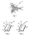
- FIG. 1shows a connecting region of two sheets in a sectional illustration
- FIG. 2shows the connecting region in a side view with holes and a peripheral contour
- FIG. 3shows the connecting region in a side view with a wavy contour
- FIGS. 4 a – 4 cshow a second embodiment of the connecting region in a sectional illustration, with FIG. 4 a showing a spot welding connection, FIG. 4 b showing a connection with joints passing through it, and FIG. 4 c showing a rivet connection, and
- FIG. 5shows the second embodiment of the connecting region in a side view.
- FIG. 1shows a connecting region 1 a of two sheets 2 a in a sectional view.
- the two sheets 2 amay be of any desired, and even different, materials, in particular of materials which can be welded together with difficulty or not at all, such as high-strength and/or galvanized steels or plastics or aluminium.
- the connecting region 1 ais formed by two overlapping flanges of the sheets 2 a .
- the flangesare angled away from each other in a peripheral region 4 a , with the result that the connecting region 1 a has a V profile in cross section.
- a strip-shaped fastening element 5 ais also illustrated. This fastening element 5 a encloses, in cross section, the outer contour of the flanges which are angled away from each other.
- the connecting region 1 ais designed in such a manner that some sections of the inner side 7 of the fastening element 5 a rest on the surfaces 9 of the flanges in the wedge-shaped cavity 8 formed by the two angled flanges.
- the inner side 7 of the fastening element 5 aalso rests on the surfaces 9 of the sheets 2 a in the region which is remote from the peripheral region 4 a and in which the sheets 2 a come into contact with each other.
- the effect achieved by the fastening element 5 a resting in the angled peripheral region 4 ais that the fastening element 5 a cannot become detached from the flanges in the direction of the sheet edge 10 .
- an adhesive 11can be provided between the inner side 7 of the fastening element 5 a and the surface 9 .
- a plurality of holes 12 lying next to one anotherare provided parallel to the sheet edge 10 in at least one of the two flanges, in the region remote from the peripheral region 4 a .
- a deformation region 13 of the fastening element 5 awhich region in each case lies opposite the holes 12 , is pressed into these holes 12 in order to ensure that the fastening element 5 a cannot be displaced relative to the flanges in the direction perpendicular with respect to the plane of projection.
- such holes 12 lying opposite one anotherare provided in both flanges.
- FIG. 2shows the connecting region 1 a without the fastening element 5 a in a side view.
- the holes 12 in the flangescan be seen clearly here.
- FIG. 2shows a further measure with which displacement of the fastening element 5 a relative to the flanges is prevented: the flanges have, in the peripheral region 4 a , a peripheral contour 14 which fixes the fastening element 5 a on the sheet edge 10 .
- the peripheral contour 14has a wavy shape here, but a tooth-shaped or triangular contour may also be selected.
- FIG. 3An alternative possibility for fixing the fastening element is illustrated in FIG. 3 .
- the peripheral region 4 b of the flangeshas a wavy contour 15 which prevents the fastening element from being displaced in the longitudinal direction of the flanges.
- FIGS. 4 a – 4 cillustrate a second embodiment of the connecting region in sectional views, with FIG. 4 a being a view along line IVa—IVa of FIG. 5 and with FIGS. 4 b and 4 c being similar views of alternative connections.
- the flangeshere are not angled away from each other in the peripheral regions 4 a or 4 b , but rather rest on each other over the entire connecting region 1 c , 1 d , or 1 e . This embodiment is advantageous if the structural space is not sufficient in order to provide angled flanges.
- the outer contour of the flangesis enclosed by a respective fastening element 5 c , 5 d , or 5 e , and some sections of the inner side 7 of the fastening element rest on the surface 9 c , 9 d , or 9 e of the flanges, in the region remote from the peripheral region. Furthermore, the flanges have overlapping through-holes 12 . As in the first exemplary embodiment, adhesive 11 may also be provided here between the inner side 7 of the fastening element 5 c , 5 d , or 5 e and the surface 9 c , 9 d , or 9 e of the sheets 2 c , 2 d , or 2 e , respectively.
- the holes 12are provided with such a width that it is possible within the holes 12 to connect the deformation region 13 of the fastening element 5 c , 5 d , or 5 e , which region has been pressed into the holes 12 , non-releasably to an opposite region 16 of the fastening element 5 c , 5 d , or 5 e .
- the fastening element 5 c , 5 d , or 5 eis of a material which can be joined more easily, for example a conventional steel material.
- both the deformation region 13 and the opposite region 16are pressed into the holes 12 , but it is also possible to press only the deformation region 13 into the holes 12 before connection takes place.
- FIG. 4 ashows, as a second possibility, the regions—the deformation region 13 and opposite region 16 —connected by means of joints passing through them, while in FIG. 4 c , a rivet 17 connecting the two regions is illustrated.
- FIG. 4 cshows, as a second possibility, the regions—the deformation region 13 and opposite region 16 —connected by means of joints passing through them, while in FIG. 4 c , a rivet 17 connecting the two regions is illustrated.
- Which of the three methods is used in each casedepends, firstly, on the material of the fastening element 5 c , 5 d , or 5 e and, secondly, on the available space for carrying out the connecting method.
- FIG. 5shows the connecting region 1 c once again in a side view.
- the two deformation regions 13are connected here by a welding point 18 , for example.
- the method according to the invention for producing the connecting regionproceeds in the following steps:
- one sheet or both sheets of each set of sheets 2 a – 2 eis or are provided in the connecting region 1 a – 1 e with the holes 12 which, in the case of holes 12 on both sides, lie opposite each other in the assembled state. If a connecting region 1 a or 1 b of the first embodiment is to be produced, then the flanges still have to be angled away from each other in the peripheral region 4 a or 4 b . Furthermore, in this method step, if required, the wavy contour 15 or the peripheral contour 14 can be stamped in in the peripheral region 4 a or 4 b of the flanges.
- a suitable adhesive 11is applied to regions of the inner side 7 of the fastening element and/or of the surface of the flanges.
- the strip-shaped fastening element 5 a – 5 eis folded around the outer contour of the flanges in such a manner that it encloses the outer contour and rests with some sections of its inner side 7 on the mutually remote surfaces 9 of the two flanges.
- the fastening element 5 a – 5 eis placed over the outer contour of the flanges and pressed in the regions in which it is to come into contact with the surface 9 , 9 c – 9 e of the sheets 2 a – 2 e .
- the width of the fastening elementhas to be correspondingly selected in such a manner that the holes 12 are covered.
- the length of the fastening elementis dependent on whether the entire connecting region 1 or only sections thereof are to be covered by the fastening element in the longitudinal direction.
- the use of a plurality of relatively short fastening elements which are distributed over the connecting region 1is also conceivable.
- the deformation regions 13 of the fastening element 5 a – 5 ewhich regions lie opposite the holes 12 , are pressed into the holes 12 .
- the deformation region 13is then connected non-releasably to the opposite region 16 of the fastening element 5 c , 5 d , or 5 e by spot welds (according to FIG. 4 a ), joints passing through them (according to FIG. 4 b ) or rivets (according to FIG. 4 c ).
- the connecting region and the methodare not limited to the two exemplary embodiments explained above.
- the holes 12 in the flangesdo not have to be configured as through-holes; it is also conceivable just to provide spot-facings in the flanges, into which the material of the deformation region 13 of the fastening element 5 a – 5 e is pressed.
- each fastening element 5 a – 5 ehas an inner side 7 with some sections resting on mutually remote surfaces of the flanges, and there may indeed also be sections in which there is no surface contact between the inner side 7 of the fastening element and the surface 9 of the flanges.
- connecting region 1 and the methodare not restricted to two sheets; rather, a larger number of sheets may also be connected to one another in this manner.
Landscapes
- Engineering & Computer Science (AREA)
- General Engineering & Computer Science (AREA)
- Mechanical Engineering (AREA)
- Connection Of Plates (AREA)
Abstract
Description
Claims (8)
Applications Claiming Priority (2)
| Application Number | Priority Date | Filing Date | Title |
|---|---|---|---|
| DE10220100.5 | 2002-05-04 | ||
| DE10220100ADE10220100B4 (en) | 2002-05-04 | 2002-05-04 | Edge-side connection region of two sheets |
Publications (2)
| Publication Number | Publication Date |
|---|---|
| US20040011769A1 US20040011769A1 (en) | 2004-01-22 |
| US7104719B2true US7104719B2 (en) | 2006-09-12 |
Family
ID=29285103
Family Applications (1)
| Application Number | Title | Priority Date | Filing Date |
|---|---|---|---|
| US10/428,004Expired - Fee RelatedUS7104719B2 (en) | 2002-05-04 | 2003-05-02 | Peripheral connecting region of two sheets and peripheral connection method |
Country Status (2)
| Country | Link |
|---|---|
| US (1) | US7104719B2 (en) |
| DE (1) | DE10220100B4 (en) |
Cited By (1)
| Publication number | Priority date | Publication date | Assignee | Title |
|---|---|---|---|---|
| US20170009794A1 (en)* | 2014-02-04 | 2017-01-12 | Böllhoff Verbindungstechnik GmbH | Self-piercing rivet |
Families Citing this family (1)
| Publication number | Priority date | Publication date | Assignee | Title |
|---|---|---|---|---|
| CN115647220B (en)* | 2022-10-31 | 2025-09-02 | 珠海市椿田机械科技有限公司 | An integrated traceless processing technology for press riveting and welding of sheet metal parts |
Citations (25)
| Publication number | Priority date | Publication date | Assignee | Title |
|---|---|---|---|---|
| US1244119A (en)* | 1916-12-01 | 1917-10-23 | Schriver M Mulnix | Pole-protective means. |
| FR641348A (en) | 1927-09-23 | 1928-08-01 | Device for assembling sheet metal, iron, etc. panels. | |
| US1723307A (en)* | 1928-03-07 | 1929-08-06 | Harry E Sipe | Coupling strip |
| US2036725A (en)* | 1934-05-28 | 1936-04-07 | Carl R Schlicht | Tool for seaming sheet metal |
| US2611530A (en)* | 1948-10-01 | 1952-09-23 | Gaylord Container Corp | Shipping carton with handhole reinforcing and flap securing clip |
| US2664089A (en)* | 1947-01-03 | 1953-12-29 | Guide & Supply Co Inc | Index member and adjustable indicator tab therefor |
| GB776452A (en) | 1954-08-09 | 1957-06-05 | Jackson Electric Stove Company | Improvements in or relating to the joining together of two or more vitreous enamelled metal parts |
| US2881766A (en)* | 1956-02-06 | 1959-04-14 | George B Graff Company | File tab or signal |
| US2894308A (en)* | 1957-04-15 | 1959-07-14 | Eckstein Morris | Carton flap clamp |
| US3302825A (en)* | 1964-04-15 | 1967-02-07 | Bilnor Corp | Open top liquid container |
| US3381883A (en)* | 1966-08-11 | 1968-05-07 | Claud H. Harris | Sani-seal box closure clip |
| GB1113575A (en) | 1966-02-17 | 1968-05-15 | Broderick Structures | Improvements relating to roofing or walling panels |
| US3574449A (en)* | 1969-04-29 | 1971-04-13 | Jerome Rosenberg | K for individual plastic face panels of internally illuminated sign box |
| US3864814A (en)* | 1972-07-03 | 1975-02-11 | Valmet Oy | Seaming method for sheet metal ducts |
| US3886676A (en)* | 1973-12-28 | 1975-06-03 | Louis Alfonso | Sign facing assembly |
| US4033348A (en)* | 1975-09-16 | 1977-07-05 | Johnson & Johnson | Disposable diaper having a tab fastener with a bifurcated fixed end |
| US4096603A (en)* | 1976-11-01 | 1978-06-27 | Fellowes Manufacturing Company | Drawer pull and label holder |
| GB1539747A (en) | 1975-12-30 | 1979-01-31 | Den Brink W Van | Method of fabricating ducting |
| US5024375A (en)* | 1990-03-19 | 1991-06-18 | Wright Christopher B | Closure device for reclosing a gable-top container |
| US5160175A (en)* | 1991-08-22 | 1992-11-03 | Yang Ming Tung | Quick pipe coupling with inflatable seal and pin retainer |
| JPH09144229A (en)* | 1995-11-27 | 1997-06-03 | Sekisui Chem Co Ltd | Roof structure and balcony |
| US5704509A (en)* | 1995-05-08 | 1998-01-06 | Allentech, Inc. | Full contact floating roof |
| US5896715A (en)* | 1996-04-02 | 1999-04-27 | S.A.R.L. A.M. Consultant | System for assembling prefabricated panels to make a wall, e.g. for a swimming pool, and a swimming pool wall obtained thereby |
| US6338184B1 (en)* | 2000-06-21 | 2002-01-15 | Illinois Tool Works Inc. | Manually-operated sealing tool for joining end portions of plastic strapping, seal member, and sealed joint formed thereby |
| US6439453B1 (en)* | 2000-10-27 | 2002-08-27 | Tetra Laval Holdings & Finance, Sa | Closure clip for gable-top carton |
- 2002
- 2002-05-04DEDE10220100Apatent/DE10220100B4/ennot_activeExpired - Fee Related
- 2003
- 2003-05-02USUS10/428,004patent/US7104719B2/ennot_activeExpired - Fee Related
Patent Citations (26)
| Publication number | Priority date | Publication date | Assignee | Title |
|---|---|---|---|---|
| US1244119A (en)* | 1916-12-01 | 1917-10-23 | Schriver M Mulnix | Pole-protective means. |
| FR641348A (en) | 1927-09-23 | 1928-08-01 | Device for assembling sheet metal, iron, etc. panels. | |
| US1723307A (en)* | 1928-03-07 | 1929-08-06 | Harry E Sipe | Coupling strip |
| US2036725A (en)* | 1934-05-28 | 1936-04-07 | Carl R Schlicht | Tool for seaming sheet metal |
| US2664089A (en)* | 1947-01-03 | 1953-12-29 | Guide & Supply Co Inc | Index member and adjustable indicator tab therefor |
| US2611530A (en)* | 1948-10-01 | 1952-09-23 | Gaylord Container Corp | Shipping carton with handhole reinforcing and flap securing clip |
| GB776452A (en) | 1954-08-09 | 1957-06-05 | Jackson Electric Stove Company | Improvements in or relating to the joining together of two or more vitreous enamelled metal parts |
| US2881766A (en)* | 1956-02-06 | 1959-04-14 | George B Graff Company | File tab or signal |
| US2894308A (en)* | 1957-04-15 | 1959-07-14 | Eckstein Morris | Carton flap clamp |
| US3302825A (en)* | 1964-04-15 | 1967-02-07 | Bilnor Corp | Open top liquid container |
| GB1113575A (en) | 1966-02-17 | 1968-05-15 | Broderick Structures | Improvements relating to roofing or walling panels |
| US3381883A (en)* | 1966-08-11 | 1968-05-07 | Claud H. Harris | Sani-seal box closure clip |
| US3574449A (en)* | 1969-04-29 | 1971-04-13 | Jerome Rosenberg | K for individual plastic face panels of internally illuminated sign box |
| US3864814A (en)* | 1972-07-03 | 1975-02-11 | Valmet Oy | Seaming method for sheet metal ducts |
| DE2332482B2 (en) | 1972-07-03 | 1978-01-12 | Valmet Oy, Helsinki | HEMING PROCESS FOR SHEET METAL DUCTS |
| US3886676A (en)* | 1973-12-28 | 1975-06-03 | Louis Alfonso | Sign facing assembly |
| US4033348A (en)* | 1975-09-16 | 1977-07-05 | Johnson & Johnson | Disposable diaper having a tab fastener with a bifurcated fixed end |
| GB1539747A (en) | 1975-12-30 | 1979-01-31 | Den Brink W Van | Method of fabricating ducting |
| US4096603A (en)* | 1976-11-01 | 1978-06-27 | Fellowes Manufacturing Company | Drawer pull and label holder |
| US5024375A (en)* | 1990-03-19 | 1991-06-18 | Wright Christopher B | Closure device for reclosing a gable-top container |
| US5160175A (en)* | 1991-08-22 | 1992-11-03 | Yang Ming Tung | Quick pipe coupling with inflatable seal and pin retainer |
| US5704509A (en)* | 1995-05-08 | 1998-01-06 | Allentech, Inc. | Full contact floating roof |
| JPH09144229A (en)* | 1995-11-27 | 1997-06-03 | Sekisui Chem Co Ltd | Roof structure and balcony |
| US5896715A (en)* | 1996-04-02 | 1999-04-27 | S.A.R.L. A.M. Consultant | System for assembling prefabricated panels to make a wall, e.g. for a swimming pool, and a swimming pool wall obtained thereby |
| US6338184B1 (en)* | 2000-06-21 | 2002-01-15 | Illinois Tool Works Inc. | Manually-operated sealing tool for joining end portions of plastic strapping, seal member, and sealed joint formed thereby |
| US6439453B1 (en)* | 2000-10-27 | 2002-08-27 | Tetra Laval Holdings & Finance, Sa | Closure clip for gable-top carton |
Cited By (2)
| Publication number | Priority date | Publication date | Assignee | Title |
|---|---|---|---|---|
| US20170009794A1 (en)* | 2014-02-04 | 2017-01-12 | Böllhoff Verbindungstechnik GmbH | Self-piercing rivet |
| US10876565B2 (en)* | 2014-02-04 | 2020-12-29 | Böhoff Verbindungstechnik GmbH | Self-piercing rivet |
Also Published As
| Publication number | Publication date |
|---|---|
| DE10220100A1 (en) | 2003-11-27 |
| DE10220100B4 (en) | 2004-05-06 |
| US20040011769A1 (en) | 2004-01-22 |
Similar Documents
| Publication | Publication Date | Title |
|---|---|---|
| US6048628A (en) | Multiple-plate structure of zonal design for a shaped part | |
| JP2005508796A (en) | Force strut brace | |
| CN107922009B (en) | Vehicle body structure of vehicle | |
| JP2005527421A (en) | Three-dimensional connection structure | |
| WO2008058765A1 (en) | Multi-part component, in particular a multi-part heat shield | |
| US20060017305A1 (en) | Low-profile high-strength vehicle door beam | |
| US20050258667A1 (en) | Sheet steel connection joints of sections consisting of sheet steel | |
| US7104719B2 (en) | Peripheral connecting region of two sheets and peripheral connection method | |
| JP2001130449A (en) | Composite structure, especially composite structure suitably usable as front face support for automobile | |
| US9969433B2 (en) | Method for manufacturing a hollow profile, a hollow profile and a vehicle body | |
| JPH0995257A (en) | Glued connection structure | |
| JP3941501B2 (en) | Vehicle body front frame structure and vehicle body front frame connection method | |
| JPH09193634A (en) | Suspension arm for automobile | |
| US20030184109A1 (en) | Method for producing a structural element with a reinforced bend and a structural element | |
| JP2002364624A (en) | Aluminum panel fastening site structure | |
| JPH0221610Y2 (en) | ||
| JPH0314341Y2 (en) | ||
| JP2645810B2 (en) | End member of shell connected to exhaust pipe | |
| JPS602998Y2 (en) | Automobile seat belt anchor attachment structure | |
| JPH0562241B2 (en) | ||
| JP2606673Y2 (en) | Temporary fixing structure for metal members | |
| JP4147611B2 (en) | Connecting structure and connecting method of vehicle front pillar and cowl | |
| JPH0137952Y2 (en) | ||
| JPH06239267A (en) | Joint structure of pillar upper section | |
| JP3853503B2 (en) | Column and beam connection structure |
Legal Events
| Date | Code | Title | Description |
|---|---|---|---|
| AS | Assignment | Owner name:DAIMLERCHRYSLER AG, GERMANY Free format text:ASSIGNMENT OF ASSIGNORS INTEREST;ASSIGNORS:FUSSNEGGER, WOLFGANG;SCHEFFZUEK, MATTIAS;REEL/FRAME:014469/0115;SIGNING DATES FROM 20030514 TO 20030521 | |
| AS | Assignment | Owner name:DAIMLER AG, GERMANY Free format text:CHANGE OF NAME;ASSIGNOR:DAIMLERCHRYSLER AG;REEL/FRAME:020976/0889 Effective date:20071019 Owner name:DAIMLER AG,GERMANY Free format text:CHANGE OF NAME;ASSIGNOR:DAIMLERCHRYSLER AG;REEL/FRAME:020976/0889 Effective date:20071019 | |
| REMI | Maintenance fee reminder mailed | ||
| LAPS | Lapse for failure to pay maintenance fees | ||
| STCH | Information on status: patent discontinuation | Free format text:PATENT EXPIRED DUE TO NONPAYMENT OF MAINTENANCE FEES UNDER 37 CFR 1.362 | |
| FP | Lapsed due to failure to pay maintenance fee | Effective date:20100912 | |
| AS | Assignment | Owner name:DAIMLER AG, GERMANY Free format text:CORRECTIVE ASSIGNMENT TO CORRECT THE APPLICATION NO. 10/567,810 PREVIOUSLY RECORDED ON REEL 020976 FRAME 0889. ASSIGNOR(S) HEREBY CONFIRMS THE CHANGE OF NAME;ASSIGNOR:DAIMLERCHRYSLER AG;REEL/FRAME:053583/0493 Effective date:20071019 |