US7104312B2 - Method and apparatus for achieving temperature uniformity and hot spot cooling in a heat producing device - Google Patents
Method and apparatus for achieving temperature uniformity and hot spot cooling in a heat producing deviceDownload PDFInfo
- Publication number
- US7104312B2 US7104312B2US10/698,304US69830403AUS7104312B2US 7104312 B2US7104312 B2US 7104312B2US 69830403 AUS69830403 AUS 69830403AUS 7104312 B2US7104312 B2US 7104312B2
- Authority
- US
- United States
- Prior art keywords
- fluid
- heat exchanger
- heat
- exchanger according
- layer
- Prior art date
- Legal status (The legal status is an assumption and is not a legal conclusion. Google has not performed a legal analysis and makes no representation as to the accuracy of the status listed.)
- Expired - Lifetime, expires
Links
- 238000000034methodMethods0.000titleclaimsabstractdescription69
- 238000001816coolingMethods0.000titleclaimsdescription45
- 239000012530fluidSubstances0.000claimsabstractdescription482
- 230000005465channelingEffects0.000claimsabstractdescription15
- 230000005514two-phase flowEffects0.000claimsdescription20
- 239000011248coating agentSubstances0.000claimsdescription14
- 238000000576coating methodMethods0.000claimsdescription14
- 239000011148porous materialSubstances0.000claimsdescription11
- 230000004044responseEffects0.000claimsdescription10
- 230000007704transitionEffects0.000claimsdescription6
- 238000004891communicationMethods0.000claimsdescription5
- 230000008878couplingEffects0.000claims1
- 238000010168coupling processMethods0.000claims1
- 238000005859coupling reactionMethods0.000claims1
- 238000007788rougheningMethods0.000claims1
- 239000012071phaseSubstances0.000description46
- 238000009835boilingMethods0.000description18
- 238000013461designMethods0.000description17
- 238000010586diagramMethods0.000description14
- 230000007423decreaseEffects0.000description9
- 239000000463materialSubstances0.000description9
- 239000007788liquidSubstances0.000description8
- 230000000694effectsEffects0.000description7
- 230000004907fluxEffects0.000description7
- 238000012546transferMethods0.000description7
- 230000001419dependent effectEffects0.000description5
- 230000007246mechanismEffects0.000description5
- 239000000203mixtureSubstances0.000description4
- 238000010438heat treatmentMethods0.000description3
- 230000037361pathwayEffects0.000description3
- 230000008859changeEffects0.000description2
- 230000003247decreasing effectEffects0.000description2
- 230000002093peripheral effectEffects0.000description2
- 238000010521absorption reactionMethods0.000description1
- 230000001133accelerationEffects0.000description1
- 238000010276constructionMethods0.000description1
- 229910003460diamondInorganic materials0.000description1
- 239000010432diamondSubstances0.000description1
- 230000006870functionEffects0.000description1
- 239000007791liquid phaseSubstances0.000description1
- 238000004519manufacturing processMethods0.000description1
- 238000012986modificationMethods0.000description1
- 230000004048modificationEffects0.000description1
- 239000011368organic materialSubstances0.000description1
- 230000001012protectorEffects0.000description1
- 238000000926separation methodMethods0.000description1
- 229910001285shape-memory alloyInorganic materials0.000description1
- 239000011343solid materialSubstances0.000description1
- 239000003351stiffenerSubstances0.000description1
- 230000002123temporal effectEffects0.000description1
- 238000011144upstream manufacturingMethods0.000description1
Images


Classifications
- F—MECHANICAL ENGINEERING; LIGHTING; HEATING; WEAPONS; BLASTING
- F28—HEAT EXCHANGE IN GENERAL
- F28F—DETAILS OF HEAT-EXCHANGE AND HEAT-TRANSFER APPARATUS, OF GENERAL APPLICATION
- F28F3/00—Plate-like or laminated elements; Assemblies of plate-like or laminated elements
- F28F3/02—Elements or assemblies thereof with means for increasing heat-transfer area, e.g. with fins, with recesses, with corrugations
- F28F3/04—Elements or assemblies thereof with means for increasing heat-transfer area, e.g. with fins, with recesses, with corrugations the means being integral with the element
- F28F3/048—Elements or assemblies thereof with means for increasing heat-transfer area, e.g. with fins, with recesses, with corrugations the means being integral with the element in the form of ribs integral with the element or local variations in thickness of the element, e.g. grooves, microchannels
- F—MECHANICAL ENGINEERING; LIGHTING; HEATING; WEAPONS; BLASTING
- F04—POSITIVE - DISPLACEMENT MACHINES FOR LIQUIDS; PUMPS FOR LIQUIDS OR ELASTIC FLUIDS
- F04B—POSITIVE-DISPLACEMENT MACHINES FOR LIQUIDS; PUMPS
- F04B19/00—Machines or pumps having pertinent characteristics not provided for in, or of interest apart from, groups F04B1/00 - F04B17/00
- F04B19/006—Micropumps
- F—MECHANICAL ENGINEERING; LIGHTING; HEATING; WEAPONS; BLASTING
- F28—HEAT EXCHANGE IN GENERAL
- F28D—HEAT-EXCHANGE APPARATUS, NOT PROVIDED FOR IN ANOTHER SUBCLASS, IN WHICH THE HEAT-EXCHANGE MEDIA DO NOT COME INTO DIRECT CONTACT
- F28D15/00—Heat-exchange apparatus with the intermediate heat-transfer medium in closed tubes passing into or through the conduit walls ; Heat-exchange apparatus employing intermediate heat-transfer medium or bodies
- F—MECHANICAL ENGINEERING; LIGHTING; HEATING; WEAPONS; BLASTING
- F28—HEAT EXCHANGE IN GENERAL
- F28F—DETAILS OF HEAT-EXCHANGE AND HEAT-TRANSFER APPARATUS, OF GENERAL APPLICATION
- F28F3/00—Plate-like or laminated elements; Assemblies of plate-like or laminated elements
- F28F3/12—Elements constructed in the shape of a hollow panel, e.g. with channels
- F—MECHANICAL ENGINEERING; LIGHTING; HEATING; WEAPONS; BLASTING
- F28—HEAT EXCHANGE IN GENERAL
- F28F—DETAILS OF HEAT-EXCHANGE AND HEAT-TRANSFER APPARATUS, OF GENERAL APPLICATION
- F28F2260/00—Heat exchangers or heat exchange elements having special size, e.g. microstructures
- F28F2260/02—Heat exchangers or heat exchange elements having special size, e.g. microstructures having microchannels
- H—ELECTRICITY
- H01—ELECTRIC ELEMENTS
- H01L—SEMICONDUCTOR DEVICES NOT COVERED BY CLASS H10
- H01L23/00—Details of semiconductor or other solid state devices
- H01L23/34—Arrangements for cooling, heating, ventilating or temperature compensation ; Temperature sensing arrangements
- H01L23/42—Fillings or auxiliary members in containers or encapsulations selected or arranged to facilitate heating or cooling
- H01L23/427—Cooling by change of state, e.g. use of heat pipes
- H—ELECTRICITY
- H01—ELECTRIC ELEMENTS
- H01L—SEMICONDUCTOR DEVICES NOT COVERED BY CLASS H10
- H01L23/00—Details of semiconductor or other solid state devices
- H01L23/34—Arrangements for cooling, heating, ventilating or temperature compensation ; Temperature sensing arrangements
- H01L23/46—Arrangements for cooling, heating, ventilating or temperature compensation ; Temperature sensing arrangements involving the transfer of heat by flowing fluids
- H01L23/473—Arrangements for cooling, heating, ventilating or temperature compensation ; Temperature sensing arrangements involving the transfer of heat by flowing fluids by flowing liquids
- H—ELECTRICITY
- H01—ELECTRIC ELEMENTS
- H01L—SEMICONDUCTOR DEVICES NOT COVERED BY CLASS H10
- H01L2924/00—Indexing scheme for arrangements or methods for connecting or disconnecting semiconductor or solid-state bodies as covered by H01L24/00
- H01L2924/0001—Technical content checked by a classifier
- H01L2924/0002—Not covered by any one of groups H01L24/00, H01L24/00 and H01L2224/00
- Y—GENERAL TAGGING OF NEW TECHNOLOGICAL DEVELOPMENTS; GENERAL TAGGING OF CROSS-SECTIONAL TECHNOLOGIES SPANNING OVER SEVERAL SECTIONS OF THE IPC; TECHNICAL SUBJECTS COVERED BY FORMER USPC CROSS-REFERENCE ART COLLECTIONS [XRACs] AND DIGESTS
- Y10—TECHNICAL SUBJECTS COVERED BY FORMER USPC
- Y10T—TECHNICAL SUBJECTS COVERED BY FORMER US CLASSIFICATION
- Y10T29/00—Metal working
- Y10T29/49—Method of mechanical manufacture
- Y10T29/4935—Heat exchanger or boiler making
Definitions
- the inventionrelates to a method of and apparatus for cooling a heat producing device in general, and specifically, to a method of and apparatus for reducing temperature differences and achieving hot spot cooling in a heat source.
- microchannel heat sinksSince their introduction in the early 1980's, microchannel heat sinks have shown much potential for high heat-flux cooling applications and have been used in the industry.
- existing microchannelsinclude conventional parallel channel arrangements which are not optimally suited for cooling heat producing devices which have spatially-varying heat loads. Such heat producing devices have areas which produce more heat per unit area than others. These hotter areas are hereby designated as “hot spots” whereas the areas of the heat source which do not produce as much heat are hereby termed, “warm spots”.
- a hot spotis an area of a heat source, for example a microprocessor, which has a substantially higher heat flux than the other areas of the heat source.
- a substantially varying heat flux across the surface of the heat sourcecan induce temperature differences along the heat source surface, thereby forming multiple hot spots.
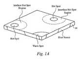
- FIG. 1Aillustrates a perspective view of a heat source 99 having multiple hot spots therein.
- the hot spotshave a higher heat flux than other areas in the heat source
- a peripheral area proximal to the hot spotalso has a higher temperature relative to the non-hot spot areas, due to the propagation of heat through the heat source material. Therefore, the area shown within the dashed lines in FIG. 1A that is peripheral to the hot spots are higher in temperature than the areas outside of the dashed lines. Therefore, the hot spot area as well as the immediate surrounding area is defined as the hot spot and is called an interface hot spot region.
- FIG. 1Billustrates a perspective view of a heat source 99 having no hot spots therein along with an aligned graph which represents the temperature variation as a function of distance in the X and Y directions.
- the heat source 99 in FIG. 1Bdoes not have any hot spots, the physics of heat propagation in materials dictates that the middle of the heat source 99 will have a higher heat flux than the surrounding areas and edges of the heat source 99 . This is shown in the graph in FIG. 1 B.
- Prior art heat exchangersonly focus on cooling the heat source and thereby do not focus on the aspects of hot spot cooling or overall temperature uniformity.
- What is neededis a fluidic cooling loop system with a heat exchanger utilizing various design controls and cooling methods to achieve temperature uniformity in the heat source. What is also needed is a fluidic cooling loop system with a heat exchanger utilizing various design and control methods to effectively cool hot spots in a heat source.
- One aspect of the inventionis directed to a method of controlling temperature of a heat source in contact with a heat exchanging surface of a heat exchanger, wherein the heat exchanging surface is substantially aligned along a plane.
- the methodcomprises channeling a first temperature fluid to the heat exchanging surface, wherein the first temperature fluid undergoes thermal exchange with the heat source along the heat exchanging surface.
- the methodcomprises channeling a second temperature fluid from the heat exchange surface, wherein fluid is channeled to minimize temperature differences along the heat source.
- the heat exchangercomprises a first layer that is in substantial contact with the heat source.
- the first layeris configured to perform thermal exchange with fluid flowing in the first layer, wherein the first layer is aligned along a first plane.
- the heat exchangercomprises a second layer that is coupled to the first layer and channels fluid to and from the first layer.
- the heat exchangeris configured to minimize temperature differences along the heat source.
- the systemcomprises at least one heat exchanger for controlling the temperature of the heat source.
- the heat exchangerfurther comprises an interface layer that is in substantial contact with the heat source and is configured to channel fluid along at least one thermal exchange path, whereby the interface layer is configured along a first plane.
- the heat exchangeralso further comprises a manifold layer which delivers inlet fluid along at least one inlet path and removes outlet fluid along at least one outlet path.
- the heat exchangeris configured to achieve substantial temperature uniformity in the heat source.
- the systemalso comprises at least one pump for circulating fluid throughout the loop. The at least one pump is coupled to the at least one heat exchanger.
- the systemalso comprises at least one heat rejector which is coupled to the at least one pump and the at least one heat exchanger.
- the second layerfurther comprises a plurality inlet fluid paths which are configured substantially perpendicular to the first plane.
- the second layeralso includes a plurality of outlet paths which are configured substantially perpendicular to the first plane, wherein the inlet and outlet paths are arranged parallel with one another.
- the second layerfurther comprises a plurality inlet fluid paths which are configured substantially perpendicular to the first plane.
- the second layeralso includes a plurality of outlet paths which are configured substantially perpendicular to the first plane, wherein the inlet and outlet paths are arranged in non-parallel relation with one another.
- the second layerfurther comprises a first level which has at least one first port that is configured to channel fluid to the first level and a second level having at least one second port. The second level is configured to channel fluid from the first level to the second port, wherein fluid in the first level flows separately from the fluid in the second level.
- the fluidis in single phase, two phase, or a transition between single and two phase flow.
- the fluidis channeled along at least one fluid path which is configured to apply a desired fluidic resistance to the fluid
- the fluid pathsinclude a length dimension and a hydraulic dimension wherein the hydraulic dimension varies with respect to the flow length dimension.
- the hydraulic dimensionis adjustable in response to one or more operating conditions in the heat exchanger.
- the present inventionincludes a means for sensing at least one desired characteristic at a predetermined location along the fluid path.
- the fluidis directed to a first circulation path along a first desired region of the heat exchanging surface.
- the fluidis also directed to a second circulation path along a second desired region of the heat exchanging surface, wherein the first circulation path flows independently of the second circulation path.
- the heat exchange surfaceis configured to include a plurality of heat transferring features thereupon, wherein heat is transferred between the fluid and the plurality of heat transferring features. A portion of the heat exchange surface is roughened to a desired roughness to control at least one of the fluidic and thermal resistances. At least one of the heat transferring features further comprises a pillar, a microchannel and/or a microporous structure.
- the heat exchange surfaceincludes a desired number of heat transferring features disposed per unit area to control the fluidic resistance to the fluid.
- the fluidic resistanceis optimized by selecting an appropriate pore size and an appropriate pore volume fraction in a microporous structure.
- the fluidic resistanceis optimized by selecting an appropriate number of pillars and an appropriate pillar volume fraction in the unit area. In another embodiment, the fluidic resistance is optimized by selecting an appropriate hydraulic diameter for at least one microchannel.
- the heat transferring featurehas a length dimension which is optimized to control the fluidic resistance to the fluid. At least one dimension of at least a portion of the heat transferring feature is optimized to control the fluidic resistance to the fluid. Alternatively, a distance between two or more heat transferring features is optimized to control the fluidic resistance to the fluid. Alternatively, a coating is applied upon at least a portion of at least one heat transferring feature in the plurality to control at least one of the thermal and fluidic resistances.
- a surface area of at least one heat transferring featureis optimized to control the thermal and fluidic resistances to the fluid.
- At least one flow impeding elementis configured along the fluid path, wherein the at least one flow impeding element controls a resistance. Additionally, a pressure of the fluid is adjusted at a predetermined location along the fluid path to control an instantaneous temperature of the fluid. A flow rate of the fluid is also adjusted at a predetermined location along the flow path to control an instantaneous temperature of the fluid.
- FIG. 1Aillustrates a perspective view of a heat source having multiple hot spots marked thereon.
- FIG. 1Billustrates a Temperature-Position graph of a typical heat source having uniform heating.
- FIG. 2Aillustrates a schematic diagram of a closed loop cooling system incorporating a microchannel heat exchanger of the present invention.
- FIG. 2Billustrates a schematic diagram of a closed loop cooling system incorporating a microchannel heat exchanger with multiple pumps of the present invention.
- FIG. 3Aillustrates a perspective view of the interface layer having several microchannels disposed thereon.
- FIG. 3Billustrates a perspective view of the interface layer having several different heat transferring features disposed thereon with differing dimensions.
- FIG. 3Cillustrates a perspective view of the interface layer having a varying density of several micro-pillars disposed thereon.
- FIG. 3Dillustrates a perspective view of the interface layer having several micro-pillars and fins disposed thereon.
- FIG. 4Aillustrates an exploded view of one embodiment of the heat exchanger coupled to a heat source in accordance with the present invention.
- FIG. 4Billustrates a top view of the one embodiment of the heat exchanger with variably moveable fingers coupled to a heat source in accordance with the present invention.
- FIG. 5illustrates a cut-away perspective view of another embodiment of the heat exchanger in accordance with the present invention.
- FIG. 6illustrates an exploded view of the another embodiment of the heat exchanger in accordance with the present invention.
- FIG. 7Aillustrates a perspective view of another embodiment of the heat exchanger in accordance with the present invention.
- FIG. 7Billustrates a top view of the one embodiment of the heat exchanger with variably moveable fingers coupled to a heat source in accordance with the present invention.
- FIG. 8Aillustrates a schematic diagram of the thermal resistance to fluid flow circulated to the heat exchanger of the present invention by one pump.
- FIG. 8Billustrates a schematic diagram of the thermal resistance to fluid flow circulated to the heat exchanger of the present invention by multiple pumps.
- FIG. 9illustrates a perspective view of microchannels and micro-pillars having a cut-away feature in accordance with the present invention.
- FIG. 10illustrates a Pressure versus Flow Rate diagram of a fluid circulating through a heat exchanger.
- a closed-loop fluid systemoperating in conjunction with a heat exchanger to capture thermal energy generated from a heat source by passing fluid through selective areas of the interface layer in contact with the heat source.
- the fluidcan be directed in one or two phase flow to specific areas in the interface layer to cool hot spots and/or to reduce temperature differences across the heat source while maintaining an optimal pressure drop within the heat exchanger.
- achieving temperature uniformityencompasses minimizing temperature gradients that occur automatically in any heat source.
- achieving temperature uniformity in the heat sourceencompasses minimizing temperature gradients in the absence of hot spots, as in FIG. 1 B. Therefore, achieving temperature uniformity includes reducing temperatures differences between the hotter areas, warmer areas and cooler areas in the heat source.
- the heat exchanger as well as the closed loop system of the present inventionemploy different design concepts and control methods to achieve temperature uniformity throughout the heat source.
- microchannel heat exchanger of the present inventionis described and discussed in relation to cooling hot spot locations in a device, the heat exchanger is alternatively used for heating a cold spot location in a device to achieve temperature uniformity in the heat source. It should also be noted that although the present invention is preferably described as a microchannel heat exchanger, the present invention can be used in other applications and is not limited to the discussion herein.
- FIG. 2Aillustrates a schematic diagram of a hermetically scaled closed loop cooling system 30 which includes the microchannel heat exchanger 100 of the present invention.
- FIG. 2Billustrates a schematic diagram of an alternative hermetically sealed closed loop cooling system 30 ′ which includes the microchannel heat exchanger 100 ′ with multiple ports 108 ′, 109 ′ coupled to multiple pumps 32 ′ and a diverting valve 33 ′.
- the diverting valve 33 ′ and multiple pumps 32 ′supply more than one fluid stream to the heat exchanger 100 ′.
- the system 30 , 30 ′alternatively incorporates additional components not shown in the figures and is not limited to tho configuration shown.
- the fluid ports 108 , 109are coupled to fluid lines 38 which are coupled to a pump 32 and a heat condensor 30 .
- the pump 32pumps and circulates fluid within the closed loop 30 .
- a uniform, constant amount of fluid flowenters and exits the heat exchanger 100 via the respective fluid ports 108 , 109 .
- variable amounts of fluid flowenter and exit through the inlet and outlet port(s) 108 ′, 109 of the heat exchanger 100 at a given time.
- two or more pumps 32 ′provide fluid to several designated inlet ports 108 ′ via one or more valves 33 ′. It will be apparent that the architectures shown in FIGS. 2A and 2B are representative only. Any number of pumps and fluid ports can be provided.
- one or more sensors 130 , 130 ′are coupled to the heat exchanger 100 , 100 ′ and/or heat source 99 , 99 ′ whereby the sensors 130 , 130 ′ provide information of the operating conditions in the heat exchanger 100 , 100 to a dynamic sensing and control module 34 , 34 ′
- the control module 34 , 34 ′is coupled to the pumps 32 , 32 ′ and/or heat exchanger 100 , 100 ′ and dynamically controls the amount and flow rate of fluid entering and exiting the beat exchanger 100 , 100 ′ in response to information received from the one or more sensors 130 , 130 ′ regarding changes in heat, hot spot locations, flow rates, fluid temperatures, pressure of the fluid and general operation of the system 30 , 30 ′.
- control module 34 ′initiates operation of both pumps 32 ′ in response to an increase in the amount of heat in a hot spot location. It should be noted that the sensing and control module 34 , 34 ′ is applicable to both cooling systems, as shown in FIGS. 2A-2B .
- the interface layer 102( FIGS. 3A and 4A ) is preferably in contact with the heat source and provides heat exchange capabilities to adequately cool the heat source 99 .
- the interface layer 102is integrally formed within the heat source as one entire component.
- the interface layer 102is incorporated into a heat spreader (not shown), whereby the heat spreader is either coupled to or integrally formed within the heat source.
- the interface layer 102 of the heat exchanger 100is configured to allow fluid to flow thereupon.
- the interface layer 102allows heat transfer from the heat source 99 to the fluid by conduction as well as convection.
- the interface layerincludes any number of similar or different heat transferring features, some of which are described below. It should be apparent to one skilled in the art that the heat transferring features are not limited to the shapes discussed below and alternatively incorporate other appropriate shapes and designs.
- FIG. 3Aillustrates a perspective view of the of the interface layer 102 having several microchannels 110 disposed thereon in accordance with the present invention.
- the microchannels 110allow the fluid to undergo thermal exchange along the entire interface layer 102 and/or selected hot spot locations of the interface hot spot region to cool the heat source 99 .
- the microchannel walls 110extend vertically from the bottom surface of the interface layer and are preferably configured to be parallel, as shown in FIG. 3 A. Alternatively, the microchannel walls 110 are configured to be non-parallel.
- FIG. 3Billustrates a perspective view of the of the interface layer 102 ′ having several different heat transferring features disposed along the interface layer in accordance with the present invention.
- the interface layer 102 ′includes multiple microchannels 109 , wherein two of the microchannels are of the same shape and one microchannel 111 has a portion extending taller than the other portion.
- the interface layer 102 ′includes several pillars 132 , 134 of various height dimensions disposed thereon in accordance with the present invention. As shown in FIG. 3B , the pillars 134 extend vertically from the bottom surface of the interface layer 102 to a predetermined height, potentially the entire height of the interface layer 102 ′.
- the pillars 132extend vertically an amount less than the pillars 134 .
- the pillars 134can have any shape including, but not limited to, squared (FIG. 3 B), diamond (not shown), elliptical (not shown), hexagonal (not shown), circular or any other shape.
- the interface layeralternatively has a combination of differently shaped pillars disposed thereupon.
- FIG. 38illustrates a microporous structure 136 disposed on the bottom surface of the interface layer 102 ′.
- the heat exchanger 100 of the present inventionis larger in width than the heat source 99 .
- an overhang dimensionexists.
- the overhang dimensionis the farthest distance between one outer wall of the heat source 99 and the interior fluid channel wall of the heat exchanger 100 .
- the overhang dimensionis within the range of and including 0 to 5 millimeters for single phase and 0 to 15 millimeters for two phase fluid.
- the interface layer 102 of the present inventionpreferably has a thickness dimension within the range of and including 0.3 to 0.7 millimeters for single phase fluid and 0.3 to 1.0 millimeters for two phase fluid.
- the microporous structure 136has an average pore size within the range of and including 10 to 200 microns for single phase as well as two phase fluid.
- the microporous structure 136has a porosity within the range and including 50 to 80 percent for single phase as well as two phase fluid.
- the height of the microporous structure 136is within the range of and including 0.25 to 2.00 millimeters for single phase as well as two phase fluid.
- the interface layer 102 of the present inventionhas a thickness dimension in the range of and including 0.3 to 0.7 millimeters for single phase fluid and 0.3 to 1.0 millimeters for two phase fluid.
- the area of at least one pillar 132is in the range of and including (10 micron) 2 and (100 micron) 2 for single phase as well as two phase fluid.
- the area of the separation distance between at least two of the pillars 132 and/or microchannels 109is in the range of and including 10 to 150 microns for single phase as well as two phase fluid.
- the width dimension of the microchannels 109in the range of and including 10 to 100 microns for single phase as well as two phase fluid.
- the height dimension of the microchannels 109 and/or pillars 132is within the range of and including 50 to 800 microns for single phase fluid and 50 microns to 2 millimeters for two phase fluid. It is contemplated by one skilled in the art that other dimension are alternatively contemplated.
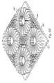
- the interface layer 102 ′′′includes several sets of rectangular fins 138 ′′′ which are radially disposed with respect to one another in their respective set.
- the interface layer 102 ′′′includes several pillars 134 ′′′ disposed between the sets of rectangular fins 138 ′′′.
- the interface layer 102can include one type of heat transferring feature or alternatively any combination of different heat transferring features (e.g. microchannels, pillars, micro-porous structures).
- the interface layer 102preferably has a high thermal conductivity which minimizes the temperature differences between the heat source 99 and the fluid flowing along the interface layer 102 .
- the interface layeris preferably made from a material having a high thermal conductivity of 100 W/m-K.
- the heat transferring featurespreferably have thermal conductivity characteristics of at least 10 W/m-K. However, it is apparent to one skilled in the art that the interface layer 102 and heat transferring features have a thermal conductivity of more or less than the preferred amount and is not limited thereto. More details regarding the interface layer as well as the heat transferring features are discussed in co-pending patent application Serial No. Cool-01301, filed on Oct. 6, 2003, and entitled “METHOD AND APPARATUS FOR EFFICIENT VERTICAL FLUID DELIVERY FOR COOLING A HEAT PRODUCING DEVICE”, which is hereby incorporated by reference.
- FIG. 4Aillustrates an exploded view of one embodiment of the heat exchanger 100 in accordance with the present invention.
- the top surface of the manifold layer 106is partially cut away to illustrate the channels 116 , 122 and fingers 118 , 120 within the body of the manifold layer 106 .
- the locations in the heat source 99 ′ that produce more heat as well as the region that surrounds that locationare hereby designated as interface hot spot regions, whereby the locations in the heat source 99 ′ which produce less heat are hereby designated as warm spot regions.
- the heat source 99 ′is shown to have hot spot regions at locations A and B.
- the interface layer 102includes interface hot spot region A, which is positioned above hot spot location A and interface hot spot region B, which is positioned above hot spot location B.
- fluidinitially enters the heat exchanger 100 through one inlet port 108 , although more than one inlet port 108 is contemplated. The fluid then flows to an inlet channel 116 .
- the heat exchanger 100includes more than one inlet channel 116 .
- fluid flowing along the inlet channel 116 from the inlet port 108initially branches out to finger 118 D.
- the fluid which continues along the rest of the inlet channel 116flows to individual fingers 118 B and 118 C and so on.
- fluidis supplied to interface hot spot region A by flowing to the finger 118 A, whereby fluid flows down in the Z-direction through finger 118 A to the intermediate layer 104 .
- the fluidthen flows through an inlet conduit 105 A in the interface intermediate layer 104 which is positioned below the finger 118 A, to the interface layer 102 .
- the fluidpreferably travels along the microchannels 110 as shown in FIG. 4 A and undergoes thermal exchange with the heat source 99 ′.
- the heated liquidthen travels upward in the Z-direction through the conduit 105 B to the outlet finger 120 A.
- fluidflows down in the Z-direction through fingers 118 E and 118 F to the intermediate layer 104 .
- the fluidthen flows through the inlet conduit 105 C down in the Z-direction to the interface layer 102 .
- the heated fluidthen travels upward in the Z-direction from the interface layer 102 through the outlet conduit 105 D to the outlet fingers 120 E and 120 F.
- the heat exchanger 100removes the heated fluid in the manifold layer 106 via the outlet fingers 120 , whereby the outlet fingers 120 are in communication with the outlet channel 122 .
- the outlet channel 122allows fluid to flow out of the heat exchanger 100 through one or more outlet ports 109 .
- FIG. 5illustrates a broken-perspective view of another embodiment of the heat exchanger 200 in accordance with the present invention.
- the heat exchanger 200is divided into separate regions dependent on the amount of heat produced along the body of the heat source 99 ′′.
- the divided regionsare separated by the vertical intermediate layer 204 and/or microchannel wall features 210 in the interface layer 202 .
- the regions in the interface layer 202are divided by vertical walls which extend between the interface layer and intermediate layer 204 , as shown by the dashed lines in FIG. 5 .
- the assembly shown in FIG. 5is not limited to the configuration shown and is for exemplary purposes.
- the heat source 99 ′′has a hot spot in location A′ and a warm spot, in location B′, whereby the hot spot in location A′ produces more heat than the warm spot in location B′. It is apparent that the heat source 99 ′′ alternatively has more than one hot spot and/or warm spot at any location at any given time. Accordingly, more fluid and/or a higher rate of liquid flow is provided to the interface hot spot region A′ in the heat exchanger 200 to adequately cool location A′. It is apparent that although interface hot spot region B′ is shown to be larger than interface hot spot region A′, interface hot spot regions A′ and B′, as well as any other interface hot spot regions in the heat exchanger 200 , can be any size and/or configuration with respect to one another.
- the heat exchanger 200is coupled to two or more pumps, as shown in FIG. 5 , whereby each pump 32 ′ ( FIG. 2B ) provides its own or multiple fluid loops within the heat exchanger 200 .
- each pump 32 ′FIG. 2B
- the heat exchanger 200is coupled to one pump 32 (FIG. 2 A).
- the fluidenters the eat exchanger 200 via fluid ports 208 A and is directed to interface hot spot region A by flowing along the intermediate layer 204 A to the inflow conduits 205 A.
- the fluidthen flows down the inflow conduits 205 A in the Z-direction into the interface hot spot region A of the interface layer 202 A.
- the fluidflows in between the microchannels 210 A whereby heat from location A′ transfers to the fluid by conduction through the interface layer 202 A.
- the heated fluidflows along the interface layer 202 in interface hot spot region A′ toward exit port 209 A where the fluid exits the heat exchanger 200 . It is apparent to one skilled in the art that any number of inlet ports 208 and exit ports 209 are utilized for a particular interface hot spot region or a set of interface hot spot regions.
- the heat source 99 ′′ in FIG. 5has a warm spot in location B′ which produces less heat than location A′.
- Fluid entering through the port 208 Bis directed to interface hot spot region B′ by flowing along the intermediate layer 204 B to the inflow conduits 205 B.
- the fluidthen flows down the inflow conduits 205 B in the Z-direction into interface hot spot region B of the interface layer 202 B.
- the fluidflows and is channeled along the microchannels 210 B, whereby heat generated by the heat source in location B′ is transferred to the fluid.
- the heated fluidflows along the entire interface layer 202 B in interface hot spot region B and upward to exit ports 209 B in the Z-direction via the outflow conduits 205 B in the intermediate layer 204 B.
- the fluidthen exits the heat exchanger 200 through the exit parts 209 B.
- the heat exchanger 200is coupled to one pump 32 as shown in the closed loop system 30 (FIG. 2 A). In another embodiment, the heat exchanger 200 is coupled to more than one pump 32 ′, whereby a set of input ports 208 A and output ports 209 A are coupled to one pump (pump 1 ) whereas another set of input ports 208 B and output ports 209 B are coupled to another pump (pump 2 ).
- the valve 33 ′FIG. 2B
- the heat exchanger 200is designed in one embodiment to keep a desired fraction of the flow separate such that fluid from one pump does not mix with fluid from another pump.
- the heat exchanger 200 in FIG. 5has an independent fluid loop to interface hot spot region A and another independent fluid loop to interface hot spot region B.
- the independent loops in the heat exchanger 200are used to achieve temperature uniformity and effectively cool the hot spots in the heat source 99 ′′.
- the independent fluid loopscan be used to supply a consistent amount of fluid to one or more interface hot spot region as well as the remaining portion of the interface layer.
- FIG. 6illustrates an exploded view of another embodiment of the heat exchanger 300 in accordance with the present invention.
- the manifold layer 306 shown in FIG. 6includes three individual levels.
- the manifold layer 306includes a circulation level 304 , an inlet level 308 and an outlet level 312 .
- the circulation level 304is not utilized, whereby the interface layer 302 is coupled directly to the inlet level 308 .
- cooled fluidenters the heat exchanger 300 through the inlet port 315 in the outlet level 312 .
- the cooled fluidtravels down the inlet port 315 to the inlet port 314 in the inlet level 308 .
- the fluidthen flows into the corridor 320 and flows downward in the Z-direction to the interface layer 302 via the inlet apertures 322 in the circulation level 304 .
- the cooled fluid in the inlet corridor 320does not mix or come into contact with any heated fluid exiting the heat exchanger 300 .
- the fluid entering the interface layer 302undergoes thermal exchange with the solid material and absorbs the heat produced in the heat source 99 .
- the inlet apertures 322 and outlet apertures 324are arranged such that the fluid travels the optimal closest distance along the interface layer 302 from each inlet aperture 322 to an adjacent outlet aperture 324 .
- the optimal distance between the inlet and outlet aperturesreduces the pressure drop therebetween while effectively cooling the heat source 99 .
- the heated fluidthen travels upward in the Z-direction from the interface layer 302 through the inlet level 308 via the several outlet apertures 324 to the outlet corridor 32 S in the outlet level 312 .
- the heated fluidtravels upward in the Z-direction from the interface layer 302 directly to the outlet corridor 328 in the outlet level 312 .
- the heated fluidupon entering the outlet corridor 328 in the outlet level 312 flows to the outlet port 316 and exits the heat exchanger 300 .
- the heated fluiddoes not mix or come into contact with any cooled fluid entering the manifold layer 306 as it exits the heat exchanger 300 . It is apparent that the fluid flow shown by the arrows in FIG. 6 is alternatively reversed.
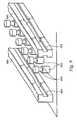
- FIG. 7Aillustrates a perspective view of another embodiment of the heat exchanger 400 in accordance with the present invention.
- the manifold layer 406 in FIG. 7Aincludes a plurality of interwoven or inter-digitated parallel fluid fingers 411 , 412 which allow one phase and/or two-phase fluid to circulate to the interface layer 402 without allowing a substantial pressure drop from occurring within the heat exchanger 400 and the system 30 . 30 ′ (FIGS. 2 A- 2 B).
- the inlet fingers 411are arranged alternately with the outlet fingers 412 in the heat exchange 400 .
- fluidenters the manifold layer 406 at fluid port 408 and travels through the passage 414 and towards the fluid fingers or passages 411 .
- the fluidenters the opening of the inlet fingers 411 and flows the length of the fingers 411 in the X-direction, as shown by the arrows.
- the fluidflows downward in the Z direction to the interface layer 402 .
- the fluid in the interface layer 402traverses along the bottom surface in the X and Y directions and performs thermal exchange with the heat source 99 .
- the heated fluidexits the interface layer 402 by flowing upward in the Z-direction via the outlet fingers 412 , whereby the outlet fingers 412 channel the heated fluid to the passage 418 in the manifold layer 406 in the X and Y directions.
- the fluidthen flows along the passage 418 and exits the heat exchanger by flowing out through the port 409 .
- the closed fluid loop 30 , 30 ′( FIGS. 2A-2B ) as well as the heat exchanger 100 can be configured to cool hot spots in the heat source 99 and/or achieve an overall temperature uniformity in the heat source 99 .
- the present inventioneffectively cools the hot spots by applying a higher flow rate of fluid and/or colder fluid to an interface hot spot region. This is initially described above in relation to the heat exchangers 100 , 200 , 300 , 400 shown in FIGS. 4-7A .
- FIGS. 4-7AFor sake of clarity, when referring to all the heat exchangers discussed above, the following discussion will reference heat exchanger 100 generally. However, if specific mention to a particular heat exchanger is needed, the corresponding reference number of that heat exchanger will be denoted.
- One method of achieving temperature uniformity in the heat source 99 and effective cooling of hot spotsis by controlling the hydraulic and thermal resistances in the heat exchanger 100 .
- another method of reducing temperature differences and achieving effective cooling of hot spotsis by configuring the heat exchanger 100 to have variable hydraulic resistance along the manifold layer 106 , interface layer 102 and/or intermediate layer 104 .
- another method of reducing temperature variations and achieving temperature uniformity in the heat source 99is by utilizing multiple pumps or channeling different amounts of flow from one or more pumps to independently cool specific desired areas in the interface layer 102 .
- FIG. 8Aillustrates a diagram of the hydraulic or fluidic resistances that the fluid potentially experiences in circulating through the heat exchanger.
- the heat exchanger 100has one interface hot spot region, shown in the left branch in the diagram and one interface warm spot region, shown as the right branch in the diagram.
- the discussion of the resistance diagram in FIG. 8Ais alternatively applicable to any other heat exchanger and is not limited to the heat exchanger 100 in FIG. 4 A.
- only one hot spot and warm spot resistance branchis shown in FIG. 8A , it is understood that any number of hot spots and cooler spot branches are contemplated.
- the fluidenters through the inlet 500 and flows through the manifold layer 106 (FIG. 4 A).
- the features as well as the configuration of the fluid paths in the manifold layer 106inherently have hydraulic resistances, denoted as R HOT — MANIFOLD 502 and R WARM — MANIFOLD 504 .
- R HOT — MANIFOLD 502 and R WARM — MANIFOLD 504are hydraulic resistances.
- the fluidexperiences resistances R HOT — MANIFOLD 502 and R WARM — MANIFOLD 504 in the manifold layer 106 in flowing to the interface layer 102 .
- fluidflows through the intermediate layer 104 (FIG.
- R HOT — INTERFACE 510 and R WARM — INTERFACE 512whereby the fluid experiences resistances R HOT — INTERFACE 510 and R WARM — INTERFACE 512 in the interface layer 102 .
- the heated fluidthen flows up through the intermediate layer 104 and the manifold layer 106 , whereby the heated fluid experiences resistances R HOT — INTERMEDIATE 514 , R WARM — INTERMEDIATE 516 and R HOT — MANIFOLD 518 , and R WARM — MANIFOLD 520 in the intermediate layer 104 and manifold layer 106 , respectively.
- the heated fluidthen flows out of the heat exchanger 100 through the outlet 522 .
- FIG. 8Billustrates a resistance diagram of the hydraulic resistance that the fluid potentially experiences in circulating through the heat exchanger. Although only one hot spot and warm spot resistance branch is shown in FIG. 8B , it is understood that any number of hot spots and cooler spot branches are contemplated.
- the resistance diagram in FIG. 8Bis conceptually the same as that shown in FIG. 8A , although the two fluid pumps are coupled to the heat exchanger 100 .
- Pump 1circulates fluid to the hot spots, whereby the fluid flowing to and from the interface hot spot region is subjected to the individual resistances in the heat exchanger.
- Pump 2circulates fluid to the cooler regions (e.g. warm spots), whereby the fluid flowing to and from the cooler regions is subjected to the individual resistances in the heat exchanger.
- the heat exchanger 100 of the present inventioncan be configured such that the hydraulic and thermal resistances are independently or collectively controlled to reduce temperature differences and achieve temperature uniformity in the heat source 99 and effective hot spot cooling.
- more than one pumpis employed in the system 30 ′ (FIG. 2 B), whereby more and/or colder fluid is channeled to the hot spot region and less and/or warmer fluid is channeled to the warm spot regions.
- the heat exchanger 100is configured to have a lower hydraulic resistance along the hot spot branch, R HOT — MANIFOLD 502 , R HOT — INTERMEDIATE 506 , R HOT — INTERFACE 510 , whereas the heat exchanger is configured to have a higher resistance in the warm spot branch, R WARM — MANIFOLD 504 , R WARM — INTERMEDIATE 516 and R WARM — INTERFACE 512 .
- the thermal resistanceis also controllable to allow the fluid channeled to the hot spot to undergo better thermal exchange and heat absorption than fluid channeled to the cooler region, as discussed in more detail below.
- the individual features and designs in the manifold layer 106 and intermediate layer 104can be individually or collectively varied to control the hydraulic resistance in the heat exchanger 100 .
- the geometries and cross-sectional dimensions of the fingers 118 , 120 and channels 116 , 122are tailored to provide a specific hydraulic resistance.
- the geometries and cross sectional dimensions of the conduits 105are tailored to provide a specific desired hydraulic resistance. For example, a particular finger 118 , 120 in the manifold layer 106 preferably has a larger cross sectional dimension along the location above the interface hot spot region, whereas the fingers 118 , 120 above the warm interface region has a smaller cross sectional dimension.
- the width or hydraulic dimension of the channels 116 , 122are variable along the length of the manifold layer 106 .
- the larger hydraulic dimensions of the channels 116 , 122are positioned above the interface hot spot regions and the narrower hydraulic dimensions of the channels 116 , 122 are positioned above the cooler regions. Therefore, more flow is allowed to pass over the hot spot than over the warm spot at a given time.
- the channels and/or fingershave fixed or varying hydraulic dimensions which are permanently designed into the manifold layer 106 .
- the variable hydraulic channels and/or fingersare dynamically adjustable as discussed in more detail below.
- the vertical dimensions of the fingers 118 , 120 and/or channels 116 , 122are alternatively variable to accommodate hot spot cooling and temperature uniformity in the heat source 99 .
- Channels 116 , 122 and/or fingers 118 , 120 in the manifold layer 106 which have longer side wallsallow more fluid to directly travel vertically to the interface layer 102 .
- fingers in the manifold layer 106 that do not have vertical walls which extend down to the interface layer 102allow more fluid to travel horizontally across the interface layer instead of directly striking the interface layer 102 .
- a section of a finger 118 , 120 above an interface hot spot regionhas longer side walls than other sections of that particular finger 118 , 120 .
- the longer side wallsallow fluid to be more directly applied to a concentrated area in the interface hot spot region, whereas the shorter side walls allow the fluid to be applied over a greater area in the interface layer.
- the heat exchanger 100is alternatively designed to control the hydraulic resistance R INTERFACE in the interface layer 102 to accommodate temperature uniformity and hot spot cooling in the heat source 99 .
- the heat transferring features in the interface layer 102 which are located above or near the interface hot spot regionswill have less hydraulic resistance than heat transferring features in other areas in the interface layer 102 . Therefore, more fluid is allowed to pass over the interface hot spot region than over the other areas of the interface layer at a given time, because less hydraulic resistance is present at the interface hot spot region.
- the hydraulic resistance in a fluid pathway in the interface layer 102is controlled by optimizing the hydraulic dimensions of the heat transferring features.
- the hydraulic diameter of microchannels 110are configureable to control the fluid flow rate along the length of the microchannels 110 .
- one or more microchannels in the interface layer 102has a larger diameter over the interface hot spot regions than the remaining portions of the microchannels 110 . Therefore, the larger diameter microchannels 110 will allow more fluid to pass over the interface hot spot regions than the smaller diameter microchannels 100 having more resistance.
- the pillars 134are positioned apart from each other to control the amount of hydraulic resistance upon the fluid flowing along the interface layer 102 .
- each of the pillars 134 at an interface hot spot regioncan be positioned farther apart than pillars above a warm spot region, such that more fluid is able to flow over the interface hot spot region than the warm spot region at a given time. It is apparent that the dimension of the hydraulic diameters should be optimized in light of the amount of pressure drop created in the interface layer 102 and the amount of surface area for conduction provided by the heat transferring features.
- the hydraulic resistance in a fluid pathway along the interface layer 102can alternatively be altered by optimizing the length of the fluid pathway. It is well known that the amount of hydraulic resistance increases as the length of the fluid path increases. Therefore, the length of the fluid path can be optimized to minimize the hydraulic resistance along the interface layer 102 while maintaining the pressure characteristics of the fluid.
- microchannels 110 located at an interface hot spot regionhave a smaller channel length in comparison to microchannels 110 at a warm hot spot region. Therefore, fluid traveling over the interface hot spot region flows a shorter distance along the microchannel 110 fluid paths and experiences less hydraulic resistance before exiting the interface layer, whereas the longer microchannels 110 force the fluid to travel a longer distance and cause the fluid to gradually heat up while flowing along the interface layer. It should be noted that although the length of the fluid path is optimized for single phase flow, the length of the fluid path of the microchannel 110 is alternatively made longer to induce two phase flow, as discussed in more detail below.
- the heat exchanger 100can be configured to control the thermal conductivity characteristics in the interface layer 102 to accommodate temperature uniformity and hot spot cooling in the heat source.
- the heat transferring features discussed aboveare configured to control the ability to transfer to heat from the heat transferring features to the fluid.
- the heat transferring features as well as the interface layer 102 itselfcan be configured to have one or more locations in the interface layer 102 which have a higher thermal conductivity compared to other locations in the interface layer 102 .
- One application of controlling the thermal conductivity in the interface layer 102 and/or heat transferring features 110is to form the interface layer 102 and/or heat transferring features 110 out of appropriate materials which have corresponding thermal conductivity values. For instance, a heat source 99 not having any hot spots will generate a higher heat flux in the center, as shown in FIG. 1 B. To achieve temperature uniformity in the heat source 99 shown in FIG. 1B , the interface layer 102 and/or heat transferring features are formed to provide a higher thermal conductivity in the center of the interface layer 102 . In addition, the thermal conductivity properties of the interface layer 102 and/or heat transferring features 110 gradually decreases away from the center, such that the entire heat source 99 is cooled to a substantially uniform temperature.
- the thermal resistances in the heat exchangers 100are alternatively controlled by selectively adjusting the surface to volume ratio of the heat transferring features in the interface layer 102 .
- the thermal resistance of the features and/or interface layer 102is reduced.
- One example of increasing the surface to volume ratio within the interface layer 102includes configuring the interface layer 102 to have more a greater density of heat transferring features per unit area. For example, as shown in FIG. 3B , the microchannels 110 and 111 are positioned closely to one another whereas microchannels 113 are located a further distance away from microchannels 110 and 111 .
- the microchannels 110 and 111will provide less thermal resistance to the fluid than the spaced apart microchannels 113 due to the greater surface to volume ratio of heat transferring features in the interface layer 102 ′.
- the thermal resistance of the microporous structureis reduced by utilizing smaller pore sizes.
- the heat source 99has a hot spot in each corner.
- the interface layer 102 ′′correspondingly includes an interface hot spot region in each corner as shown in FIG. 3 C.
- the interface layer 102 ′′can be configured to achieve temperature uniformity in the heat source 99 by reducing the thermal resistance along the outer corners of the interface layer 102 ′′.
- the interface layer 102 ′′thereby has a greater number of pillars 134 positioned near the outer edges of the bottom surface 101 , whereby a smaller density of pillars 134 are positioned near the center, as shown in FIG. 3 C.
- the greater density of pillars 134thereby provides a greater surface to volume ratio and a lower thermal resistance in the outer corners of the interface layer 102 ′′.
- FIG. 3Cis only one example and is not limited to the design shown therein. It should be also noted that the dimensions and volume of pillars 134 are optimized such that the fluidic resistance along the interface does not become larger than the thermal resistance.
- Another example of increasing the surface to volume ratio within the interface layer 102is to design the heat transferring features 110 at or near the interface hot spot region to have a vertical dimension that is larger than the vertical dimension of other features in the remaining areas of the interface layer 102 ′.
- the heat source 99has a large hot spot along the front half of the body. Accordingly, to achieve effective cooling of the heat source 99 , the microchannel 111 and pillars 134 have a greater vertical height near the front half of the interface layer 102 ′, whereas the microchannel 111 and pillars 132 have a smaller vertical height near the rear half of the interface layer 102 ′.
- the surface to volume ratio of the heat transferring featuresare alternatively increased by modifying the shape of the feature to have a greater surface area which the fluid is in contact with.
- the microchannels 600include a longitudinal slot 604 extending into the side of the walls 600 .
- the pillars 602include a notch 606 cut out from the body of the pillar 602 .
- the slots 602 in the microchannels 600provide additional surface area for the fluid to come into contact with.
- the notches 606 in the pillars 602provide additional surface area for the fluid to come into contact with. The additional surface area provides more space for heat to transfer to the fluid, thereby reducing the thermal resistance in the interface layer.
- the additional surface area from the slots 604 and notches 606reduces superheating and promote stable boiling of the fluid in the vicinity of the hot spots in two phase flow. It is apparent that the heat transferring features alternatively have any other configuration to provide an increased surface area to the fluid and the increased surface features shown on the microchannels 600 and pillars 602 in FIG. 9 are exemplary.
- the heat transferring featuresare additionally configureable such that the surfaces of the heat transferring features are roughened a certain degree at locations where more heat transfer is desired.
- a roughened surfacecreates pockets which bubbles from the liquid form within, whereby surface tension along the surface holds the bubbles to the roughened surface.
- the surface tension along the microchannel walls 110is changed, thereby increasing or decreasing the amount of vapor pressure needed to initiate boiling of the liquid.
- a surface which is substantially roughwill require less vapor pressure to initiate boiling, whereas a substantially smooth surface will require more vapor pressure to initiate boiling.
- boilingis desired at interface hot spot regions to achieve effective cooling of the hot spot, as discussed in more detail below. Therefore, the heat transferring features 110 as well as the interface layer 102 can have a roughened surface achieve effective cooling of the hot spot.
- the desired surface or surfaces in the interface layer 102are roughened using conventional surface altering methods.
- the desired surface or surfaces in the interface layer 102are roughened by applying a coating to the desired surface.
- the surface coating applied to the interface layer 102 and/or heat transferring elements 110modifies the surface tension of the surface.
- the surface coatingis alternatively applied to modify the contact angle at which the two phase fluid comes into contact with the surface.
- the surface coatingis preferably the same material applied to alter the thermal conductivity of the interface layer 102 and/or heat transferring features, whereby the thermal conductivity of the coating is at least 10 W/m-K.
- the surface coatingis made of a material different than the material of the interface layer 102 .
- the heat exchanger 100In addition to controlling the cooling ability of the heat exchanger 100 by altering the thermal and hydraulic resistances, the heat exchanger 100 also achieves temperature uniformity and hot spot cooling in the heat source 99 by exploiting the temperature-dependent viscosity characteristics of the fluid. As known in the art, the viscosity of most fluids decreases with increasing temperature, whereby the fluid becomes less resistive to flow as the fluid temperatures increases. Therefore, hotter areas in the interface layer 102 will naturally draw more fluid thereto than cooler areas due to this reduced hydraulic resistance and viscosity.
- the heat exchanger 100 of the present inventionutilizes this property of the fluid in its design.
- the heat exchangerinitially directs the fluid to the interface hot spot regions, wherein heat transfer from the hot spots will naturally cause the fluid to increase in temperature.
- the fluiditself will become less viscous.
- the heat exchanger 100is configureable to initially channel fluid to hotter areas in the interface layer 102 to increase the fluid temperature. The heated, less viscous fluid is then channeled at a faster flow rate to the remaining areas of the interface layer 102 .
- the fluidis heated to reduce its viscosity, the heating of the fluid can cause the fluid to boil and accelerate as vapor, thereby causing a substantial increase in the pressure drop along the interface layer 102 .
- the heat exchanger 100compensates for the potential pressure drop by constricting the flow and preventing the fluid from accelerating. This is performed using a variety of methods, such as designing the fluid paths to have very narrow pores, channels and/or spaces between the heat transferring features or utilizing multiple pumps, as discussed above. In another embodiment, as discussed below, the fluid is purposely allowed to undergo boiling to further cool desired areas in the interface layer 102 .
- the heat exchanger 100 of the present inventionincludes an internal valving mechanism to achieve temperature uniformity and perform effective cooling of hot spots in the heat source 99 .
- the internal valving mechanism in the heat exchanger 100controls the fluid flow to selected regions in the interface layer 102 .
- the internal valving mechanism in the heat exchanger 100dynamically controls the hydraulic and thermal resistance along the fluid path to achieve desired cooling effects in the system 30 , 30 ′ (FIGS. 2 A- 2 B). It is apparent to one skilled in the art that the internal valving mechanism of the heat exchanger 100 allows the system 30 , 30 ′ to control the fluid flow rate as well as the amount of flow in the heat exchanger 100 . Further, the internal valving mechanism is alternatively utilized to control the phase characteristics as well as any pressure-dependent or viscosity dependent characteristics of the fluid in the heat exchanger 100 .
- FIGS. 4B and 7Billustrate alternative embodiments of the manifold layer 106 ′, 406 ′ having multiple internal valves configured within.
- the manifold layer 106 ′includes an expandable valve 124 ′ along the channel wall 116 ′ near the inlet port 108 ′ as well as another expandable valve 126 ′ which extends around the corner along the inlet channel 116 ′.
- the manifold layer 106 ′includes an expandable valve 128 ′ in the outlet finger.
- the valves 124 ′ and 128 ′are shown in FIG. 4B to be expanded, whereas the valve 126 ′ is shown to be contracted.
- the expanded valve 124 ′also controls the flow rate as well as the amount of flow which is channeled to the remaining portion of the inlet channel 116 ′. For instance, the amount of fluid will increase at aperture 119 ′ as the valve 124 ′ is contracted, because the fluid path at the valve 124 ′ is increased in dimension.
- the expanded valve 128 ′ in the outlet finger 120 ′also controls the flow rate as well as the amount of flow which is channeled to the remaining portion of the outlet finger 120 ′.
- the valve 126 ′as shown in FIG. 4B , provides smaller hydraulic resistance to the fluid than valve 124 ′, although the valve 126 ′ is also expandable to increase the hydraulic resistance to the fluid.
- the manifold layer 406 ′includes expandable valves 424 ′ and 428 ′ coupled to the inside walls of inlet fingers 411 ′.
- the manifold layer 406 ′includes an expandable valve 426 ′ coupled to one side in the outlet finger 412 ′.
- portions of the valve 424 ′alternatively expand and/or contract independently of one another. For example, as shown in FIG. 7B , one side of the valve 424 ′ is expanded whereas the other side of the valve 424 ′ is contracted. In contrast, the entire valve 426 ′ in FIG.
- valve 7Bis substantially expanded, whereas the entire valve 428 ′ is contracted.
- the expandable valvesare alternatively disposed along any channel or fluid path in the manifold layer.
- one or more expandable valveare alternatively configured within the apertures 322 , 324 in the heat exchanger 300 in FIG. 6 .
- the expandable valvesare configured in the conduits 105 in the intermediate layer 104 .
- the expandable valvesare configured along the interface layer 102 .
- the valvecan be placed uniformly along the wall surface, as shown with valve 428 ′ in FIG. 7 B.
- valvecan be disposed on the wall surface non-uniformly, such as several bumps or other shaped protrusions which are individually expandable and contractible.
- the individual protrusion-like valvesare alternatively useable to selectively increase the surface to volume ratio in the interface layer 102 . It should be noted that fixed or variable valves are also applicable to the embodiment shown in FIG. 6 although not shown.
- the expandable valveis a shape memory alloy or a differential thermal expansion element.
- the expandable valveis a conventional or MEMS type valve.
- the expandable valveis alternatively made of a temperature driven bi-material which senses the temperature difference and automatically contracts or expands in response to the temperature difference.
- the expandable valveis alternatively made of a thermo-pneumatic material.
- the valvealternatively has a bladder configuration which contains expandable organic material having a high expansion coefficient.
- the expandable valveis a capacitive valve which actively deflects between a contracted and expanded state to deliver or restrict the amount of fluid to a desired area.
- the cooling system 30 , 30 ′utilizes sensors 130 in the heat exchanger 100 to dynamically control the one or more pumps 32 ′ ( FIG. 2B ) and/or valves inside or outside of the heat exchanger 100 .
- the heat source 99alternatively has characteristics in which the locations of one or more of the hot spots change due to different tasks required to be performed by the heat source 99 .
- the heat source 99alternatively has characteristics in which the heat flux of the one or more of the hot spots change over time due to different tasks required to be performed by the heat source 99 .
- the sensors 130provide information to the control module 34 including, but not limited to, the flow rate of fluid flowing in the interface hot spot region, temperature of the interface layer 102 in the interface hot spot region and/or heat source 99 and temperature of the fluid.
- the system 30 , 30 ′includes a sensing and control module 34 , 34 ′ ( FIGS. 2A-2B ) which dynamically changes the amount of flow and/or flow rate of fluid entering the heat exchanger 100 in response to information provided by the sensors 130 .
- FIGS. 2A and 2Billustrate the heat exchanger 100 having multiple sensors 130 , 130 ′ placed within to sense the conditions of the heat source 99 as well as provide other information to the control module 34 , 34 ′.
- the one or mores sensors 130are placed in the interface layer 102 and/or alternatively the heat source 99 at any desired location.
- the sensors 130 , 130 ′ and control module 34 , 34 ′are also coupled to the one or more pumps 32 ′ (FIGS. 2 A- 2 B), whereby the information provided by the sensors 130 to the control module 34 actively controls the pump 32 .
- the plurality of sensors 130 ′are coupled to the control module 34 ′, whereby the control module 34 ′ is preferably placed upstream from heat exchanger 100 , as shown in FIGS. 2A-2B .
- the control module 34is placed at any other location in the closed loop system 30 .
- one pump 3 ′which is operating at a lower power will increase its output upon receiving information that a particular region in the interface layer 102 is increasing in temperature, thereby causing more fluid to be delivered to that particular region.
- the sensors 130 ′ and control module 38 ′alternatively control the flow of fluid to the desired interface hot spot regions via the one or more valves.
- the expandable valve 426 ′ shown in FIG. 7Bcan be configured to expand or contract in response to information provided by the sensors 130 .
- the heat exchanger 100alternatively employs pressure-dependent boiling point conditions to achieve temperature uniformity and effective cooling of the hot spots in the heat source 99 .
- pressure-dependent boiling point conditionsto achieve temperature uniformity and effective cooling of the hot spots in the heat source 99 .
- the temperature and boiling point of a two-phase fluidis directly proportional to the pressure of the fluid. In particular, as the amount of pressure in the fluid increases, the temperature and boiling point of the fluid increases. In contrast, as the amount of pressure decreases in the fluid, the temperature and boiling point of the fluid decreases.
- the heat exchanger 100utilizes this pressure/temperature phenomenon of the fluid under single or two phase flow to effectively cool the hot spots and achieve temperature uniformity in the heat source 99 .
- the heat exchanger 100is configured to channel fluid that is a relatively low pressure and temperature to one or more desired interface hot spot regions, whereas the heat exchanger 100 simultaneously channels fluid to other parts of the interface layer 102 which is at a relatively higher pressure and temperature.
- the lower temperature fluid subjected to the hot spotswill effectively cool the hot spots to a desired temperature while the higher temperature fluid will cool the warm or cold spots to the same desired temperature.
- the single phase flowachieves temperature uniformity in the heat source 99 by directing fluid at the adequate temperature to the desired locations in the interface layer 102 to effectively cool the locations to a desired temperature.
- the heat exchanger 100 of the present inventionis configured to channel fluid using the same pressure-temperature phenomenon discussed above.
- the heat exchanger 100 of the present inventionsupplies lower pressure fluid to the interface hot spot regions to purposely create a pressure drop at the interface hot spot regions. It is well known that boiling of a two phase fluid causes a significant pressure drop due to a substantial increase in acceleration of the two phase fluid. As stated above regarding the pressure-temperature relationship, a significant drop in fluid pressure will naturally cause the temperature to significantly drop to a temperature corresponding with the reduced pressure. Accordingly, the heat exchanger 100 is configureable to channel two phase fluid already at a relatively lower pressure to the interface hot spot regions.
- the heat exchanger 100is configureable to channel fluid at a relatively higher pressure to cooler areas of the interface layer 102 .
- the lower pressure fluidupon coming into contact with the interface hot spot region, will significantly heat up and begin to boil at a much lower boiling point, thereby generating a pressure drop.
- the temperature of the boiling two phase fluideffectively decreases.
- the two phase fluidbecomes cooler and is able to more effectively cool the hot spot. It is apparent that the same theory applies in the reversing two phase fluid into single phase fluid to achieve temperature uniformity in the heat source 99 .
- the heat exchanger 100 of the present inventionachieves temperature uniformity along the entire heat source 99 using multiple operating points of single and two-phase fluids.
- FIG. 10illustrates a graph of pressure drop versus flow rate of fluid in a typical heat exchanger coupled to a microprocessor chip. As shown in FIG. 10 , the pressure of the fluid flowing along the interface layer 102 in the liquid region linearly increases with the flow rate. However, as the fluid flow rate decreases, the fluid undergoes enters the boiling regime and undergoes two-phase flow. As the fluid flow rate decreases in the boiling regime, the pressure of the fluid non-linearly increases. In addition, at significantly lower flow rates, the pressure of the fluid substantially increases in which the fluid at the significantly lower flow rates begins to dry up.
- the pressure of the fluidis directly proportional to the temperature of the fluid.
- the pressure of the fluidhas a relationship with the flow rate of the fluid.
- the temperature as well as the boiling point of the fluidis controllable by controlling the flow rate and/or pressure of the fluid.
- the heat exchanger 100 of the present inventionutilizes multiple fluid conditions to effectively achieve temperature uniformity in the heat source 99 .
- the heat exchanger 100is configureable to control the cooling effect of the fluid in each desired area by manipulating the fluid flow rate and/or the pressure of the fluid in the desired area using one pump 32 (FIG. 2 A).
- heat exchanger 100controls the cooling effect of the fluid in each desired area by manipulating the fluid flow rate and/or the pressure of the fluid in the desired area using multiple pumps 32 ′ (FIG. 2 B).
- the heat exchanger 100controls the pressure and/or flow rate of fluid in desired fluid paths to produce different desired effects in specific areas of the interface layer 102 .
- fluid which flows undergoing thermal exchange at a flow rate below 30 ml/minwill undergo two phase flow.
- the fluid flowing at a flow rate above 40 ml/minwill be in the liquid regime and remain in single phase.
- the heat source 99has a hot spot region in Location A and a warm spot region in Location B.
- the heat exchanger 200does not allow fluid flowing in the interface hot spot region A to come into contact with fluid flowing in the interface hot spot region B.
- the flow rate of all the fluidis increased and decreased as desired along the entire fluid path within the heat exchanger 100 by altering the hydraulic and thermal resistances in the heat exchanger 100 .
- the discussion herein related to the heat exchanger 200is for exemplary purposes and is applicable to any of the heat exchangers discussed as well as any number of hot/warm spots in the heat source 99 .
- the heat exchanger 200channels two phase fluid to the interface hot spot region A and simultaneously channels single phase fluid to interface warm spot region B to bring the entire heat source 99 to a uniform temperature.
- the heat exchanger 200 in the present inventionis able to accomplish this effect by channeling pressurized fluid at a lower flow rate to interface hot spot region A and channeling fluid at the same pressure to interface warm spot region B at a higher flow rate.
- the heat exchanger 200channels fluid at 1 psi to the interface hot spot region A at a flow rate of 20 ml/min, whereby the fluid has two phase characteristics.
- the heat exchanger 200channels fluid at 1 psi to interface warm spot region B at a flow rate of 40 ml/min, whereby the fluid has single phase characteristics.
- the flow rate of the fluidis controlled by using any of the designs and methods discussed above relating to hydraulic resistance.
- the heat transferring features in the interface layer 102support different flow rates by controlling the fluid flow along the interface layer 102 .
- configurations in the fingers, channels and/or aperturesare alternatively optimized to control the flow rate of the fluid.
- the heat exchanger 100is configured to provide more effective heat transfer to the fluid using any of the methods and designs discussed above regarding controlling the thermal resistance upon the fluid flow.
- the heat exchanger 100is coupled to more than one pump, whereby the multiple pumps 32 ′ circulate independent fluid loops which have different operating conditions in the heat exchanger 100 . It is also noted that the same phenomena applies to the heat exchanger 100 keeping the flow rate of the fluid constant whereas the pressure of the desired fluid paths are altered or controlled to achieve the same effects.
Landscapes
- Engineering & Computer Science (AREA)
- Mechanical Engineering (AREA)
- General Engineering & Computer Science (AREA)
- Physics & Mathematics (AREA)
- Thermal Sciences (AREA)
- Physical Or Chemical Processes And Apparatus (AREA)
- Cooling Or The Like Of Semiconductors Or Solid State Devices (AREA)
- Instantaneous Water Boilers, Portable Hot-Water Supply Apparatuses, And Control Of Portable Hot-Water Supply Apparatuses (AREA)
- Cooling Or The Like Of Electrical Apparatus (AREA)
Abstract
Description
Claims (165)
Priority Applications (1)
| Application Number | Priority Date | Filing Date | Title |
|---|---|---|---|
| US10/698,304US7104312B2 (en) | 2002-11-01 | 2003-10-30 | Method and apparatus for achieving temperature uniformity and hot spot cooling in a heat producing device |
Applications Claiming Priority (5)
| Application Number | Priority Date | Filing Date | Title |
|---|---|---|---|
| US42300902P | 2002-11-01 | 2002-11-01 | |
| US44238303P | 2003-01-24 | 2003-01-24 | |
| US45572903P | 2003-03-17 | 2003-03-17 | |
| US46224503P | 2003-04-11 | 2003-04-11 | |
| US10/698,304US7104312B2 (en) | 2002-11-01 | 2003-10-30 | Method and apparatus for achieving temperature uniformity and hot spot cooling in a heat producing device |
Publications (2)
| Publication Number | Publication Date |
|---|---|
| US20040112585A1 US20040112585A1 (en) | 2004-06-17 |
| US7104312B2true US7104312B2 (en) | 2006-09-12 |
Family
ID=32314962
Family Applications (1)
| Application Number | Title | Priority Date | Filing Date |
|---|---|---|---|
| US10/698,304Expired - LifetimeUS7104312B2 (en) | 2002-11-01 | 2003-10-30 | Method and apparatus for achieving temperature uniformity and hot spot cooling in a heat producing device |
Country Status (6)
| Country | Link |
|---|---|
| US (1) | US7104312B2 (en) |
| JP (1) | JP2006516068A (en) |
| AU (1) | AU2003286855A1 (en) |
| DE (1) | DE10393618T5 (en) |
| TW (1) | TWI295726B (en) |
| WO (1) | WO2004042306A2 (en) |
Cited By (107)
| Publication number | Priority date | Publication date | Assignee | Title |
|---|---|---|---|---|
| US20050280994A1 (en)* | 2003-12-15 | 2005-12-22 | Kazuaki Yazawa | Apparatus, method, and control program for cooling electronic devices |
| US20060065386A1 (en)* | 2004-08-31 | 2006-03-30 | Mohammed Alam | Self-actuating and regulating heat exchange system |
| US20060126293A1 (en)* | 2004-12-09 | 2006-06-15 | International Business Machines Corporation | Cooling apparatus for an electronics subsystem employing a coolant flow drive apparatus between coolant flow paths |
| US20070000647A1 (en)* | 2005-06-29 | 2007-01-04 | Crocker Michael T | Systems for integrated cold plate and heat spreader |
| US20070091569A1 (en)* | 2005-10-25 | 2007-04-26 | International Business Machines Corporation | Cooling apparatus and method employing discrete cold plates disposed between a module enclosure and electronics components to be cooled |
| US20070121294A1 (en)* | 2005-11-30 | 2007-05-31 | International Business Machines Corporation | Multi-element heat exchange assemblies and methods of fabrication for a cooling system |
| US20070163750A1 (en)* | 2006-01-17 | 2007-07-19 | Bhatti Mohinder S | Microchannel heat sink |
| US20080156519A1 (en)* | 2006-12-29 | 2008-07-03 | Bothhand Enterprise Inc. | Printed circuit boardc structure |
| US20080245506A1 (en)* | 2005-10-25 | 2008-10-09 | International Business Machines Corporation | Cooling appartuses with discrete cold plates compliantly coupled between a common manifold and electronics components of an assembly to be cooled |
| US20080264604A1 (en)* | 2007-04-24 | 2008-10-30 | International Business Machines Corporation | Cooling appartaus, cooled electronic module and methods of fabrication employing a manifold structure with interleaved coolant inlet and outlet passageways |
| US20090046429A1 (en)* | 2007-08-07 | 2009-02-19 | Werner Douglas E | Deformable duct guides that accommodate electronic connection lines |
| US20090061756A1 (en)* | 2007-08-30 | 2009-03-05 | Mark Germagian | System and method for cooling electronic equipment |
| US20090071625A1 (en)* | 2007-08-09 | 2009-03-19 | Coolit Systems Inc. | Fluid heat exchanger |
| US20090139701A1 (en)* | 2007-11-30 | 2009-06-04 | Qu Weilin | Two-phase cross-connected micro-channel heat sink |
| US20090200007A1 (en)* | 2008-02-13 | 2009-08-13 | Lockheed Martin Corporation | Heat exchanger having temperature-actuated valves |
| US20090200065A1 (en)* | 2005-07-07 | 2009-08-13 | Kabushiki Kaisha Toyota Jidoshokki | Heat dissipation device and power module |
| US20100012300A1 (en)* | 2006-09-29 | 2010-01-21 | Electronics And Telecommunications Research Institute | Heat uniforming device for electronic apparatus |
| WO2010017091A1 (en)* | 2008-08-05 | 2010-02-11 | Pipeline Micro, Inc. | Microscale cooling apparatus and method |
| US7715194B2 (en) | 2006-04-11 | 2010-05-11 | Cooligy Inc. | Methodology of cooling multiple heat sources in a personal computer through the use of multiple fluid-based heat exchanging loops coupled via modular bus-type heat exchangers |
| WO2010099545A1 (en)* | 2009-02-27 | 2010-09-02 | Pipeline Micro, Inc. | Microscale heat transfer systems |
| US20100241278A1 (en)* | 2008-02-28 | 2010-09-23 | International Business Machines Coporation | Variable flow computer cooling system for a data center and method of operation |
| US20100236761A1 (en)* | 2009-03-19 | 2010-09-23 | Acbel Polytech Inc. | Liquid cooled heat sink for multiple separated heat generating devices |
| US7806168B2 (en) | 2002-11-01 | 2010-10-05 | Cooligy Inc | Optimal spreader system, device and method for fluid cooled micro-scaled heat exchange |
| US20100314093A1 (en)* | 2009-06-12 | 2010-12-16 | Gamal Refai-Ahmed | Variable heat exchanger |
| US20110048687A1 (en)* | 2009-08-26 | 2011-03-03 | Munters Corporation | Apparatus and method for equalizing hot fluid exit plane plate temperatures in heat exchangers |
| US7913719B2 (en) | 2006-01-30 | 2011-03-29 | Cooligy Inc. | Tape-wrapped multilayer tubing and methods for making the same |
| US20110096503A1 (en)* | 2009-10-27 | 2011-04-28 | Industrial Idea Partners, Inc. | Utilization of Data Center Waste Heat for Heat Driven Engine |
| US7991515B2 (en) | 2007-01-15 | 2011-08-02 | Coolit Systems Inc. | Computer cooling system with preferential cooling device selection |
| US20110205707A1 (en)* | 2008-09-16 | 2011-08-25 | Sapa Profiler Ab | Component carrier |
| US8077460B1 (en) | 2010-07-19 | 2011-12-13 | Toyota Motor Engineering & Manufacturing North America, Inc. | Heat exchanger fluid distribution manifolds and power electronics modules incorporating the same |
| US20120012299A1 (en)* | 2010-07-16 | 2012-01-19 | Industrial Idea Partners, Inc. | Proportional Micro-Valve With Thermal Feedback |
| US8157001B2 (en) | 2006-03-30 | 2012-04-17 | Cooligy Inc. | Integrated liquid to air conduction module |
| US20120140416A1 (en)* | 2009-04-05 | 2012-06-07 | Dunan Microstaq, Inc. | Method and structure for optimizing heat exchanger performance |
| US8199505B2 (en) | 2010-09-13 | 2012-06-12 | Toyota Motor Engineering & Manufacturing Norh America, Inc. | Jet impingement heat exchanger apparatuses and power electronics modules |
| US8254422B2 (en) | 2008-08-05 | 2012-08-28 | Cooligy Inc. | Microheat exchanger for laser diode cooling |
| US8250877B2 (en) | 2008-03-10 | 2012-08-28 | Cooligy Inc. | Device and methodology for the removal of heat from an equipment rack by means of heat exchangers mounted to a door |
| US8327924B2 (en) | 2008-07-03 | 2012-12-11 | Honeywell International Inc. | Heat exchanger fin containing notches |
| US8391008B2 (en) | 2011-02-17 | 2013-03-05 | Toyota Motor Engineering & Manufacturing North America, Inc. | Power electronics modules and power electronics module assemblies |
| US20130070420A1 (en)* | 2011-07-25 | 2013-03-21 | International Business Machines Corporation | Flow boiling heat sink with vapor venting and condensing |
| US20130075886A1 (en)* | 2011-09-27 | 2013-03-28 | Keihin Corporation | Semiconductor device |
| US20130077255A1 (en)* | 2011-09-27 | 2013-03-28 | Keihin Corporation | Semiconductor control device |
| US8427832B2 (en) | 2011-01-05 | 2013-04-23 | Toyota Motor Engineering & Manufacturing North America, Inc. | Cold plate assemblies and power electronics modules |
| US20130146253A1 (en)* | 2011-12-13 | 2013-06-13 | John Daly | Thermal management of photonics assemblies |
| US8464781B2 (en) | 2002-11-01 | 2013-06-18 | Cooligy Inc. | Cooling systems incorporating heat exchangers and thermoelectric layers |
| US8482919B2 (en) | 2011-04-11 | 2013-07-09 | Toyota Motor Engineering & Manufacturing North America, Inc. | Power electronics card assemblies, power electronics modules, and power electronics devices |
| US20140029199A1 (en)* | 2012-07-30 | 2014-01-30 | Toyota Motor Engineering & Manufacturing North America, Inc. | Cooling apparatuses and electronics modules having branching microchannels |
| US8659896B2 (en) | 2010-09-13 | 2014-02-25 | Toyota Motor Engineering & Manufacturing North America, Inc. | Cooling apparatuses and power electronics modules |
| US20140076528A1 (en)* | 2009-06-16 | 2014-03-20 | Uop Llc | Self cooling heat exchanger |
| US8786078B1 (en) | 2013-01-04 | 2014-07-22 | Toyota Motor Engineering & Manufacturing North America, Inc. | Vehicles, power electronics modules and cooling apparatuses with single-phase and two-phase surface enhancement features |
| US8797741B2 (en)* | 2010-10-21 | 2014-08-05 | Raytheon Company | Maintaining thermal uniformity in micro-channel cold plates with two-phase flows |
| US20150009631A1 (en)* | 2013-07-05 | 2015-01-08 | Toyota Motor Engineering & Manufacturing North America, Inc. | Cooling Assemblies and Power Electronics Modules Having Multiple-Porosity Structures |
| US20150043164A1 (en)* | 2013-08-08 | 2015-02-12 | Toyota Motor Engineering & Manufacturing North America, Inc. | Jet impingement cooling apparatuses having enhanced heat transfer assemblies |
| US8960179B2 (en) | 2009-02-24 | 2015-02-24 | Carrier Corporation | Air treatment module |
| US9035452B2 (en) | 2012-08-07 | 2015-05-19 | General Electric Company | Electronic device cooling with autonomous fluid routing and method of assembly |
| US20150138730A1 (en)* | 2012-08-09 | 2015-05-21 | Fujitsu Limited | Heat receiving apparatus, cooling apparatus, and electronic apparatus |
| US9057567B2 (en) | 2007-08-09 | 2015-06-16 | Coolit Systems, Inc. | Fluid heat exchange systems |
| US9061382B2 (en) | 2011-07-25 | 2015-06-23 | International Business Machines Corporation | Heat sink structure with a vapor-permeable membrane for two-phase cooling |
| US9069532B2 (en) | 2011-07-25 | 2015-06-30 | International Business Machines Corporation | Valve controlled, node-level vapor condensation for two-phase heat sink(s) |
| US9179575B1 (en) | 2012-03-13 | 2015-11-03 | Rockwell Collins, Inc. | MEMS based device for phase-change autonomous transport of heat (PATH) |
| US20150351283A1 (en)* | 2014-05-27 | 2015-12-03 | Fujitsu Limited | Heatsink and board unit |
| US20160037680A1 (en)* | 2014-08-04 | 2016-02-04 | National Center For Advanced Packaging Co., Ltd. | Heat dissipation solution for advanced chip packages |
| US9265177B2 (en) | 2013-03-08 | 2016-02-16 | International Business Machines Corporation | Fabricating multi-component electronic module with integral coolant-cooling |
| US9285050B2 (en) | 2012-12-06 | 2016-03-15 | International Business Machines Corporation | Thermostat-controlled coolant flow within a heat sink |
| US9297571B1 (en) | 2008-03-10 | 2016-03-29 | Liebert Corporation | Device and methodology for the removal of heat from an equipment rack by means of heat exchangers mounted to a door |
| US9313921B2 (en) | 2012-08-30 | 2016-04-12 | International Business Machines Corporation | Chip stack structures that implement two-phase cooling with radial flow |
| US20160109913A1 (en)* | 2014-10-15 | 2016-04-21 | Fujitsu Limited | Cooling device and electronic apparatus |
| US20160128232A1 (en)* | 2014-10-29 | 2016-05-05 | International Business Machines Corporation | Interlayer chip cooling apparatus |
| US20160309623A1 (en)* | 2015-04-15 | 2016-10-20 | Ford Global Technologies, Llc | Vehicle Power Module Assemblies and Manifolds |
| US9496200B2 (en) | 2011-07-27 | 2016-11-15 | Coolit Systems, Inc. | Modular heat-transfer systems |
| US20170025326A1 (en)* | 2014-09-22 | 2017-01-26 | Fuji Electric Co., Ltd. | Electronic part cooler |
| US20170064866A1 (en)* | 2015-08-28 | 2017-03-02 | National Chiao Tung University | Heat conducting module |
| US9655294B2 (en) | 2010-07-28 | 2017-05-16 | Wolverine Tube, Inc. | Method of producing electronics substrate with enhanced direct bonded metal |
| US9681580B2 (en) | 2010-07-28 | 2017-06-13 | Wolverine Tube, Inc. | Method of producing an enhanced base plate |
| US9709324B1 (en)* | 2012-11-09 | 2017-07-18 | Rockwell Collins, Inc. | Liquid cooling with parasitic phase-change pumps |
| US9795057B2 (en) | 2010-07-28 | 2017-10-17 | Wolverine Tube, Inc. | Method of producing a liquid cooled coldplate |
| US9943014B2 (en) | 2013-03-15 | 2018-04-10 | Coolit Systems, Inc. | Manifolded heat exchangers and related systems |
| US20180228052A1 (en)* | 2016-09-30 | 2018-08-09 | International Business Machines Corporation | Cold plate device for a two-phase cooling system |
| US10211127B1 (en)* | 2016-03-28 | 2019-02-19 | Lockheed Martin Corporation | Integration of chip level micro-fluidic cooling in chip packages for heat flux removal |
| US10364809B2 (en) | 2013-03-15 | 2019-07-30 | Coolit Systems, Inc. | Sensors, multiplexed communication techniques, and related systems |
| US10365667B2 (en) | 2011-08-11 | 2019-07-30 | Coolit Systems, Inc. | Flow-path controllers and related systems |
| US10415597B2 (en) | 2014-10-27 | 2019-09-17 | Coolit Systems, Inc. | Fluid heat exchange systems |
| US10492334B2 (en)* | 2017-01-12 | 2019-11-26 | Rensselaer Polytechnic Institute | Methods, systems, and assemblies for cooling an electronic component |
| US10531594B2 (en) | 2010-07-28 | 2020-01-07 | Wieland Microcool, Llc | Method of producing a liquid cooled coldplate |
| US10674628B2 (en)* | 2017-05-11 | 2020-06-02 | Mersen France Sb Sas | Cooling module and power converter comprising such a cooling module |
| US10905028B2 (en)* | 2019-05-07 | 2021-01-26 | International Business Machines Corporation | Structure for eliminating the impact of cold plate fouling |
| US20210141975A1 (en)* | 2017-03-14 | 2021-05-13 | International Business Machines Corporation | Autonomous development of two-phase cooling architecture |
| US20220061187A1 (en)* | 2020-08-19 | 2022-02-24 | Baidu Usa Llc | Hybrid cooling system for electronic racks |
| US11277937B2 (en)* | 2019-07-31 | 2022-03-15 | Jetcool Technologies Inc. | Re-entrant flow cold plate |
| US20220178626A1 (en)* | 2019-05-14 | 2022-06-09 | Holo, Inc. | Devices, systems and methods for thermal management |
| US11395443B2 (en) | 2020-05-11 | 2022-07-19 | Coolit Systems, Inc. | Liquid pumping units, and related systems and methods |
| US11452243B2 (en) | 2017-10-12 | 2022-09-20 | Coolit Systems, Inc. | Cooling system, controllers and methods |
| US11473860B2 (en) | 2019-04-25 | 2022-10-18 | Coolit Systems, Inc. | Cooling module with leak detector and related systems |
| US20230040828A1 (en)* | 2021-08-06 | 2023-02-09 | Baidu Usa Llc | Chip cooling package with multiple fluid paths |
| US11662037B2 (en) | 2019-01-18 | 2023-05-30 | Coolit Systems, Inc. | Fluid flow control valve for fluid flow systems, and methods |
| US11725886B2 (en) | 2021-05-20 | 2023-08-15 | Coolit Systems, Inc. | Modular fluid heat exchange systems |
| US20230301019A1 (en)* | 2022-03-18 | 2023-09-21 | Baidu Usa Llc | System on a chip based cooling system |
| US11844193B2 (en) | 2019-04-14 | 2023-12-12 | Jetcool Technologies, Inc. | Direct contact fluid based cooling module |
| US11963341B2 (en) | 2020-09-15 | 2024-04-16 | Jetcool Technologies Inc. | High temperature electronic device thermal management system |
| US12016157B2 (en) | 2022-03-04 | 2024-06-18 | JetCool Technlologies Inc. | Actively cooled heat-dissipation lids for computer processors and assemblies |
| US12048118B2 (en) | 2021-08-13 | 2024-07-23 | Jetcool Technologies Inc. | Flow-through, hot-spot-targeting immersion cooling assembly |
| US12100643B2 (en) | 2019-04-10 | 2024-09-24 | Jetcool Technologies, Inc. | Thermal management of electronics using co-located microjet nozzles and electronic elements |
| US12141508B2 (en) | 2020-03-16 | 2024-11-12 | Washington University | Systems and methods for forming micropillar array |
| US12200914B2 (en) | 2022-01-24 | 2025-01-14 | Coolit Systems, Inc. | Smart components, systems and methods for transferring heat |
| US12289861B2 (en) | 2021-11-12 | 2025-04-29 | Jetcool Technologies Inc. | Liquid-in-liquid cooling system for electronic components |
| US12288733B2 (en) | 2021-01-20 | 2025-04-29 | Jetcool Technologies Inc. | Conformal cooling assembly with substrate fluid-proofing for multi-die electronic assemblies |
| US12289871B2 (en) | 2020-09-15 | 2025-04-29 | Jetcool Technologies Inc. | High temperature electronic device thermal management system |
| US12366870B2 (en) | 2013-03-15 | 2025-07-22 | Coolit Systems, Inc. | Flow-path controllers and related systems |
Families Citing this family (49)
| Publication number | Priority date | Publication date | Assignee | Title |
|---|---|---|---|---|
| US6881039B2 (en)* | 2002-09-23 | 2005-04-19 | Cooligy, Inc. | Micro-fabricated electrokinetic pump |
| US20050211418A1 (en)* | 2002-11-01 | 2005-09-29 | Cooligy, Inc. | Method and apparatus for efficient vertical fluid delivery for cooling a heat producing device |
| US20050211417A1 (en)* | 2002-11-01 | 2005-09-29 | Cooligy,Inc. | Interwoven manifolds for pressure drop reduction in microchannel heat exchangers |
| US7836597B2 (en) | 2002-11-01 | 2010-11-23 | Cooligy Inc. | Method of fabricating high surface to volume ratio structures and their integration in microheat exchangers for liquid cooling system |
| US20050211427A1 (en)* | 2002-11-01 | 2005-09-29 | Cooligy, Inc. | Method and apparatus for flexible fluid delivery for cooling desired hot spots in a heat producing device |
| US7201012B2 (en)* | 2003-01-31 | 2007-04-10 | Cooligy, Inc. | Remedies to prevent cracking in a liquid system |
| US7044196B2 (en)* | 2003-01-31 | 2006-05-16 | Cooligy,Inc | Decoupled spring-loaded mounting apparatus and method of manufacturing thereof |
| US20040182551A1 (en)* | 2003-03-17 | 2004-09-23 | Cooligy, Inc. | Boiling temperature design in pumped microchannel cooling loops |
| US7591302B1 (en)* | 2003-07-23 | 2009-09-22 | Cooligy Inc. | Pump and fan control concepts in a cooling system |
| US20050269691A1 (en)* | 2004-06-04 | 2005-12-08 | Cooligy, Inc. | Counter flow micro heat exchanger for optimal performance |
| US7204298B2 (en)* | 2004-11-24 | 2007-04-17 | Lucent Technologies Inc. | Techniques for microchannel cooling |
| MX2007015046A (en)* | 2005-06-07 | 2008-01-18 | Wolverine Tube Inc | Heat transfer surface for electronic cooling. |
| US20070114010A1 (en)* | 2005-11-09 | 2007-05-24 | Girish Upadhya | Liquid cooling for backlit displays |
| EP1964172A2 (en)* | 2005-12-19 | 2008-09-03 | Honeywell International Inc. | Multi-fluid coolant system |
| US20070175621A1 (en)* | 2006-01-31 | 2007-08-02 | Cooligy, Inc. | Re-workable metallic TIM for efficient heat exchange |
| US7539020B2 (en) | 2006-02-16 | 2009-05-26 | Cooligy Inc. | Liquid cooling loops for server applications |
| US20070227698A1 (en)* | 2006-03-30 | 2007-10-04 | Conway Bruce R | Integrated fluid pump and radiator reservoir |
| US7870893B2 (en)* | 2006-04-06 | 2011-01-18 | Oracle America, Inc. | Multichannel cooling system with magnetohydrodynamic pump |
| US7672129B1 (en)* | 2006-09-19 | 2010-03-02 | Sun Microsystems, Inc. | Intelligent microchannel cooling |
| CN102789226B (en)* | 2006-09-28 | 2015-07-01 | 费舍-柔斯芒特系统股份有限公司 | Abnormal situation prevention in a heat exchanger |
| DE102006050256A1 (en)* | 2006-10-23 | 2008-04-30 | Pahls, Hans-Helmut, Dipl.-Ing. | Cooler i.e. water cooler, for e.g. electronic component i.e. computer, has chambers and nozzles directly arranged in base plate, where medium flows via chambers and nozzles such that heat energy is carried from core and center of cooler |
| US20080285616A1 (en)* | 2006-12-22 | 2008-11-20 | Espec Corp. | System for testing the durability of objects under thermally hard circumstances |
| CH699934B1 (en)* | 2007-09-17 | 2011-05-31 | Vadim Anatolievich Pomytkin | Cooler for an electronic component and therefore operated electronic system. |
| US8955763B2 (en)* | 2007-10-04 | 2015-02-17 | Consolidated Edison Company Of New York, Inc. | Building heating system and method of operation |
| WO2009126339A2 (en) | 2008-01-14 | 2009-10-15 | Board Of Supervisors Of Louisiana State University And Agricultural And Mechanical College | Metal-based microchannel heat exchangers made by molding replication and assembly |
| US7866173B2 (en)* | 2008-02-28 | 2011-01-11 | International Business Machines Corporation | Variable performance server system and method of operation |
| US20110073292A1 (en)* | 2009-09-30 | 2011-03-31 | Madhav Datta | Fabrication of high surface area, high aspect ratio mini-channels and their application in liquid cooling systems |
| US20110186267A1 (en)* | 2010-02-01 | 2011-08-04 | Suna Display Co. | Heat transfer device with anisotropic thermal conducting micro structures |
| JP5609442B2 (en)* | 2010-09-02 | 2014-10-22 | 富士通株式会社 | Radiators and electronic devices |
| US9279626B2 (en)* | 2012-01-23 | 2016-03-08 | Honeywell International Inc. | Plate-fin heat exchanger with a porous blocker bar |
| JP5968425B2 (en)* | 2012-03-30 | 2016-08-10 | 京セラ株式会社 | Channel member, heat exchanger using the same, and semiconductor device |
| JP2014072265A (en)* | 2012-09-28 | 2014-04-21 | Hitachi Ltd | Cooling system, and electronic device using the same |
| US8964390B2 (en)* | 2012-11-08 | 2015-02-24 | International Business Machines Corporation | Sectioned manifolds facilitating pumped immersion-cooling of electronic components |
| JP2014183072A (en)* | 2013-03-18 | 2014-09-29 | Fujitsu Ltd | Electronic device and heat receiver |
| FR3010830B1 (en)* | 2013-09-17 | 2016-12-23 | Commissariat Energie Atomique | DEVICE FOR COOLING AN INTEGRATED CIRCUIT CHIP |
| JP6439326B2 (en) | 2014-08-29 | 2018-12-19 | 株式会社Ihi | Reactor |
| DE102014113390A1 (en)* | 2014-09-17 | 2016-03-17 | Erk Eckrohrkessel Gmbh | Heat transfer device, method for transferring heat, photovoltaic system, plate heat exchanger, method for generating electrical energy and method for providing heat |
| JP6394289B2 (en)* | 2014-11-04 | 2018-09-26 | 富士通株式会社 | Evaporator, cooling device, and electronic equipment |
| EP3259546B1 (en)* | 2015-02-19 | 2020-07-08 | JR Thermal LLC | Intermittent thermosyphon |
| US10770372B2 (en)* | 2016-09-23 | 2020-09-08 | Altera Corporation | Fluid routing devices and methods for cooling integrated circuit packages |
| US10431524B1 (en)* | 2018-04-23 | 2019-10-01 | Asia Vital Components Co., Ltd. | Water cooling module |
| KR102170654B1 (en)* | 2018-10-23 | 2020-10-28 | 한국화학연구원 | Microchannel reactor with controllability in reaction heat and control method thereof |
| JP7299017B2 (en)* | 2018-12-27 | 2023-06-27 | 川崎重工業株式会社 | Loop heat pipe and transportation |
| JP7244375B2 (en)* | 2019-07-10 | 2023-03-22 | 株式会社フジクラ | vapor chamber |
| CN112151478B (en)* | 2020-08-31 | 2022-11-11 | 中国石油大学(华东) | Micro-channel radiator and preparation method and application thereof |
| CN112696851B (en) | 2021-02-09 | 2025-05-16 | 东莞汉旭五金塑胶科技有限公司 | Improved liquid cooling head, liquid cooling head assembly and liquid cooling radiator |
| US20230126158A1 (en)* | 2021-10-27 | 2023-04-27 | Carrier Corporation | Enhanced channel configuration for heat exchanger to cool power electronics |
| CN116126039A (en)* | 2021-11-12 | 2023-05-16 | 英业达科技有限公司 | Cooling liquid flow control device |
| US12439552B2 (en)* | 2022-07-22 | 2025-10-07 | Hewlett Packard Enterprise Development Lp | Cooling module for a circuit module having a plurality of chipsets |
Citations (235)
| Publication number | Priority date | Publication date | Assignee | Title |
|---|---|---|---|---|
| US596062A (en) | 1897-12-28 | Device for preventing bursting of freezing pipes | ||
| US2039593A (en) | 1935-06-20 | 1936-05-05 | Theodore N Hubbuch | Heat transfer coil |
| US2273505A (en) | 1942-02-17 | Container | ||
| US3361195A (en) | 1966-09-23 | 1968-01-02 | Westinghouse Electric Corp | Heat sink member for a semiconductor device |
| US3654988A (en) | 1970-02-24 | 1972-04-11 | American Standard Inc | Freeze protection for outdoor cooler |
| US3771219A (en) | 1970-02-05 | 1973-11-13 | Sharp Kk | Method for manufacturing semiconductor device |
| US3817321A (en) | 1971-01-19 | 1974-06-18 | Bosch Gmbh Robert | Cooling apparatus semiconductor elements, comprising partitioned bubble pump, separator and condenser means |
| US3823572A (en) | 1973-08-15 | 1974-07-16 | American Air Filter Co | Freeze protection device in heat pump system |
| US3923426A (en) | 1974-08-15 | 1975-12-02 | Alza Corp | Electroosmotic pump and fluid dispenser including same |
| US3929154A (en) | 1974-07-29 | 1975-12-30 | Frank E Goodwin | Freeze protection apparatus |
| US3948316A (en) | 1973-02-06 | 1976-04-06 | Gaz De France | Process of and device for using the energy given off by a heat source |
| US4109707A (en) | 1975-07-02 | 1978-08-29 | Honeywell Information Systems, Inc. | Fluid cooling systems for electronic systems |
| US4194559A (en) | 1978-11-01 | 1980-03-25 | Thermacore, Inc. | Freeze accommodating heat pipe |
| US4211208A (en) | 1976-12-24 | 1980-07-08 | Deutsche Forschungs- Und Versuchsanstalt Fur Luft- Und Raumfahrt E.V. | Container for a heat storage medium |
| US4248295A (en) | 1980-01-17 | 1981-02-03 | Thermacore, Inc. | Freezable heat pipe |
| US4312012A (en) | 1977-11-25 | 1982-01-19 | International Business Machines Corp. | Nucleate boiling surface for increasing the heat transfer from a silicon device to a liquid coolant |
| US4450472A (en) | 1981-03-02 | 1984-05-22 | The Board Of Trustees Of The Leland Stanford Junior University | Method and means for improved heat removal in compact semiconductor integrated circuits and similar devices utilizing coolant chambers and microscopic channels |
| US4467861A (en) | 1982-10-04 | 1984-08-28 | Otdel Fiziko-Tekhnicheskikh Problem Energetiki Uralskogo Nauchnogo Tsentra Akademii Nauk Sssr | Heat-transporting device |
| US4485429A (en) | 1982-06-09 | 1984-11-27 | Sperry Corporation | Apparatus for cooling integrated circuit chips |
| US4516632A (en) | 1982-08-31 | 1985-05-14 | The United States Of America As Represented By The United States Deparment Of Energy | Microchannel crossflow fluid heat exchanger and method for its fabrication |
| US4540115A (en) | 1983-08-26 | 1985-09-10 | Rca Corporation | Flux-free photodetector bonding |
| US4561040A (en) | 1984-07-12 | 1985-12-24 | Ibm Corporation | Cooling system for VLSI circuit chips |
| US4567505A (en) | 1983-10-27 | 1986-01-28 | The Board Of Trustees Of The Leland Stanford Junior University | Heat sink and method of attaching heat sink to a semiconductor integrated circuit and the like |
| US4573067A (en) | 1981-03-02 | 1986-02-25 | The Board Of Trustees Of The Leland Stanford Junior University | Method and means for improved heat removal in compact semiconductor integrated circuits |
| US4574876A (en) | 1981-05-11 | 1986-03-11 | Extracorporeal Medical Specialties, Inc. | Container with tapered walls for heating or cooling fluids |
| US4644385A (en) | 1983-10-28 | 1987-02-17 | Hitachi, Ltd. | Cooling module for integrated circuit chips |
| US4664181A (en) | 1984-03-05 | 1987-05-12 | Thermo Electron Corporation | Protection of heat pipes from freeze damage |
| US4758926A (en) | 1986-03-31 | 1988-07-19 | Microelectronics And Computer Technology Corporation | Fluid-cooled integrated circuit package |
| US4866570A (en) | 1988-08-05 | 1989-09-12 | Ncr Corporation | Apparatus and method for cooling an electronic device |
| US4868712A (en) | 1987-02-04 | 1989-09-19 | Woodman John K | Three dimensional integrated circuit package |
| US4893174A (en) | 1985-07-08 | 1990-01-09 | Hitachi, Ltd. | High density integration of semiconductor circuit |
| US4894709A (en) | 1988-03-09 | 1990-01-16 | Massachusetts Institute Of Technology | Forced-convection, liquid-cooled, microchannel heat sinks |
| US4896719A (en) | 1988-05-11 | 1990-01-30 | Mcdonnell Douglas Corporation | Isothermal panel and plenum |
| US4903761A (en) | 1987-06-03 | 1990-02-27 | Lockheed Missiles & Space Company, Inc. | Wick assembly for self-regulated fluid management in a pumped two-phase heat transfer system |
| US4908112A (en) | 1988-06-16 | 1990-03-13 | E. I. Du Pont De Nemours & Co. | Silicon semiconductor wafer for analyzing micronic biological samples |
| US4938280A (en) | 1988-11-07 | 1990-07-03 | Clark William E | Liquid-cooled, flat plate heat exchanger |
| US5009760A (en) | 1989-07-28 | 1991-04-23 | Board Of Trustees Of The Leland Stanford Junior University | System for measuring electrokinetic properties and for characterizing electrokinetic separations by monitoring current in electrophoresis |
| US5016138A (en) | 1987-10-27 | 1991-05-14 | Woodman John K | Three dimensional integrated circuit package |
| US5016090A (en) | 1990-03-21 | 1991-05-14 | International Business Machines Corporation | Cross-hatch flow distribution and applications thereof |
| US5043797A (en) | 1990-04-03 | 1991-08-27 | General Electric Company | Cooling header connection for a thyristor stack |
| US5057908A (en) | 1990-07-10 | 1991-10-15 | Iowa State University Research Foundation, Inc. | High power semiconductor device with integral heat sink |
| US5058627A (en) | 1989-04-10 | 1991-10-22 | Brannen Wiley W | Freeze protection system for water pipes |
| US5070040A (en) | 1990-03-09 | 1991-12-03 | University Of Colorado Foundation, Inc. | Method and apparatus for semiconductor circuit chip cooling |
| US5083194A (en) | 1990-01-16 | 1992-01-21 | Cray Research, Inc. | Air jet impingement on miniature pin-fin heat sinks for cooling electronic components |
| US5088005A (en) | 1990-05-08 | 1992-02-11 | Sundstrand Corporation | Cold plate for cooling electronics |
| US5096388A (en) | 1990-03-22 | 1992-03-17 | The Charles Stark Draper Laboratory, Inc. | Microfabricated pump |
| US5099311A (en) | 1991-01-17 | 1992-03-24 | The United States Of America As Represented By The United States Department Of Energy | Microchannel heat sink assembly |
| US5099910A (en) | 1991-01-15 | 1992-03-31 | Massachusetts Institute Of Technology | Microchannel heat sink with alternating flow directions |
| US5125451A (en) | 1991-04-02 | 1992-06-30 | Microunity Systems Engineering, Inc. | Heat exchanger for solid-state electronic devices |
| US5131233A (en) | 1991-03-08 | 1992-07-21 | Cray Computer Corporation | Gas-liquid forced turbulence cooling |
| US5161089A (en) | 1990-06-04 | 1992-11-03 | International Business Machines Corporation | Enhanced multichip module cooling with thermally optimized pistons and closely coupled convective cooling channels, and methods of manufacturing the same |
| US5179500A (en) | 1990-02-27 | 1993-01-12 | Grumman Aerospace Corporation | Vapor chamber cooled electronic circuit card |
| US5203401A (en) | 1990-06-29 | 1993-04-20 | Digital Equipment Corporation | Wet micro-channel wafer chuck and cooling method |
| US5218515A (en) | 1992-03-13 | 1993-06-08 | The United States Of America As Represented By The United States Department Of Energy | Microchannel cooling of face down bonded chips |
| US5219278A (en) | 1989-11-10 | 1993-06-15 | Westonbridge International, Ltd. | Micropump with improved priming |
| US5228502A (en) | 1991-09-04 | 1993-07-20 | International Business Machines Corporation | Cooling by use of multiple parallel convective surfaces |
| US5230564A (en) | 1992-03-20 | 1993-07-27 | Cray Research, Inc. | Temperature monitoring system for air-cooled electric components |
| US5232047A (en) | 1991-04-02 | 1993-08-03 | Microunity Systems Engineering, Inc. | Heat exchanger for solid-state electronic devices |
| US5239443A (en) | 1992-04-23 | 1993-08-24 | International Business Machines Corporation | Blind hole cold plate cooling system |
| US5239200A (en) | 1991-08-21 | 1993-08-24 | International Business Machines Corporation | Apparatus for cooling integrated circuit chips |
| US5263251A (en) | 1991-04-02 | 1993-11-23 | Microunity Systems Engineering | Method of fabricating a heat exchanger for solid-state electronic devices |
| US5265670A (en) | 1990-04-27 | 1993-11-30 | International Business Machines Corporation | Convection transfer system |
| US5269372A (en) | 1992-12-21 | 1993-12-14 | International Business Machines Corporation | Intersecting flow network for a cold plate cooling system |
| US5275237A (en) | 1992-06-12 | 1994-01-04 | Micron Technology, Inc. | Liquid filled hot plate for precise temperature control |
| US5308429A (en) | 1992-09-29 | 1994-05-03 | Digital Equipment Corporation | System for bonding a heatsink to a semiconductor chip package |
| US5309319A (en) | 1991-02-04 | 1994-05-03 | International Business Machines Corporation | Integral cooling system for electric components |
| US5316077A (en) | 1992-12-09 | 1994-05-31 | Eaton Corporation | Heat sink for electrical circuit components |
| US5317805A (en) | 1992-04-28 | 1994-06-07 | Minnesota Mining And Manufacturing Company | Method of making microchanneled heat exchangers utilizing sacrificial cores |
| US5325265A (en) | 1988-11-10 | 1994-06-28 | Mcnc | High performance integrated circuit chip package |
| US5336062A (en) | 1990-02-27 | 1994-08-09 | Fraunhofer-Gesellschaft Zur Forderung Der Angewandten Forschung E.V. | Microminiaturized pump |
| US5346000A (en) | 1992-11-28 | 1994-09-13 | Erno Raumfahrttechnik Gmbh | Heat pipe with a bubble trap |
| US5380956A (en) | 1993-07-06 | 1995-01-10 | Sun Microsystems, Inc. | Multi-chip cooling module and method |
| US5383340A (en) | 1994-03-24 | 1995-01-24 | Aavid Laboratories, Inc. | Two-phase cooling system for laptop computers |
| US5386143A (en) | 1991-10-25 | 1995-01-31 | Digital Equipment Corporation | High performance substrate, electronic package and integrated circuit cooling process |
| US5388635A (en) | 1990-04-27 | 1995-02-14 | International Business Machines Corporation | Compliant fluidic coolant hat |
| US5421943A (en) | 1991-11-22 | 1995-06-06 | International Business Machines Corporation | Pulsed current resistive heating for bonding temperature critical components |
| US5427174A (en) | 1993-04-30 | 1995-06-27 | Heat Transfer Devices, Inc. | Method and apparatus for a self contained heat exchanger |
| US5436793A (en) | 1993-03-31 | 1995-07-25 | Ncr Corporation | Apparatus for containing and cooling an integrated circuit device having a thermally insulative positioning member |
| US5459099A (en) | 1990-09-28 | 1995-10-17 | The United States Of America As Represented By The Secretary Of The Navy | Method of fabricating sub-half-micron trenches and holes |
| US5490117A (en) | 1993-03-23 | 1996-02-06 | Seiko Epson Corporation | IC card with dual level power supply interface and method for operating the IC card |
| US5508234A (en) | 1994-10-31 | 1996-04-16 | International Business Machines Corporation | Microcavity structures, fabrication processes, and applications thereof |
| US5514906A (en) | 1993-11-10 | 1996-05-07 | Fujitsu Limited | Apparatus for cooling semiconductor chips in multichip modules |
| US5544696A (en) | 1994-07-01 | 1996-08-13 | The United States Of America As Represented By The Secretary Of The Air Force | Enhanced nucleate boiling heat transfer for electronic cooling and thermal energy transfer |
| US5548605A (en) | 1995-05-15 | 1996-08-20 | The Regents Of The University Of California | Monolithic microchannel heatsink |
| US5575929A (en) | 1995-06-05 | 1996-11-19 | The Regents Of The University Of California | Method for making circular tubular channels with two silicon wafers |
| US5579828A (en) | 1996-01-16 | 1996-12-03 | Hudson Products Corporation | Flexible insert for heat pipe freeze protection |
| US5585069A (en) | 1994-11-10 | 1996-12-17 | David Sarnoff Research Center, Inc. | Partitioned microelectronic and fluidic device array for clinical diagnostics and chemical synthesis |
| US5641400A (en) | 1994-10-19 | 1997-06-24 | Hewlett-Packard Company | Use of temperature control devices in miniaturized planar column devices and miniaturized total analysis systems |
| US5658831A (en) | 1993-03-31 | 1997-08-19 | Unisys Corporation | Method of fabricating an integrated circuit package having a liquid metal-aluminum/copper joint |
| US5675473A (en) | 1996-02-23 | 1997-10-07 | Motorola, Inc. | Apparatus and method for shielding an electronic module from electromagnetic radiation |
| US5692558A (en) | 1996-07-22 | 1997-12-02 | Northrop Grumman Corporation | Microchannel cooling using aviation fuels for airborne electronics |
| US5696405A (en) | 1995-10-13 | 1997-12-09 | Lucent Technologies Inc. | Microelectronic package with device cooling |
| US5703536A (en) | 1996-04-08 | 1997-12-30 | Harris Corporation | Liquid cooling system for high power solid state AM transmitter |
| US5704416A (en) | 1993-09-10 | 1998-01-06 | Aavid Laboratories, Inc. | Two phase component cooler |
| US5727618A (en) | 1993-08-23 | 1998-03-17 | Sdl Inc | Modular microchannel heat exchanger |
| US5740013A (en) | 1996-07-03 | 1998-04-14 | Hewlett-Packard Company | Electronic device enclosure having electromagnetic energy containment and heat removal characteristics |
| JPH1099592A (en) | 1996-09-27 | 1998-04-21 | Matsushita Electric Ind Co Ltd | Pump equipment for washing machines, etc. |
| US5759014A (en) | 1994-01-14 | 1998-06-02 | Westonbridge International Limited | Micropump |
| US5763951A (en) | 1996-07-22 | 1998-06-09 | Northrop Grumman Corporation | Non-mechanical magnetic pump for liquid cooling |
| US5768104A (en) | 1996-02-22 | 1998-06-16 | Cray Research, Inc. | Cooling approach for high power integrated circuits mounted on printed circuit boards |
| US5774779A (en) | 1996-11-06 | 1998-06-30 | Materials And Electrochemical Research (Mer) Corporation | Multi-channel structures and processes for making such structures |
| US5801442A (en) | 1996-07-22 | 1998-09-01 | Northrop Grumman Corporation | Microchannel cooling of high power semiconductor devices |
| US5800690A (en) | 1996-07-03 | 1998-09-01 | Caliper Technologies Corporation | Variable control of electroosmotic and/or electrophoretic forces within a fluid-containing structure via electrical forces |
| US5835345A (en) | 1996-10-02 | 1998-11-10 | Sdl, Inc. | Cooler for removing heat from a heated region |
| US5836750A (en) | 1997-10-09 | 1998-11-17 | Honeywell Inc. | Electrostatically actuated mesopump having a plurality of elementary cells |
| US5858188A (en) | 1990-02-28 | 1999-01-12 | Aclara Biosciences, Inc. | Acrylic microchannels and their use in electrophoretic applications |
| US5869004A (en) | 1997-06-09 | 1999-02-09 | Caliper Technologies Corp. | Methods and apparatus for in situ concentration and/or dilution of materials in microfluidic systems |
| US5870823A (en) | 1996-11-27 | 1999-02-16 | International Business Machines Corporation | Method of forming a multilayer electronic packaging substrate with integral cooling channels |
| US5874795A (en) | 1995-12-28 | 1999-02-23 | Japan Servo Co., Ltd | Multi-phase permanent-magnet type electric rotating machine |
| US5876655A (en) | 1995-02-21 | 1999-03-02 | E. I. Du Pont De Nemours And Company | Method for eliminating flow wrinkles in compression molded panels |
| US5880017A (en) | 1994-08-08 | 1999-03-09 | Hewlett-Packard Co. | Method of bumping substrates by contained paste deposition |
| US5880524A (en) | 1997-05-05 | 1999-03-09 | Intel Corporation | Heat pipe lid for electronic packages |
| US5901037A (en) | 1997-06-18 | 1999-05-04 | Northrop Grumman Corporation | Closed loop liquid cooling for semiconductor RF amplifier modules |
| US5921087A (en) | 1997-04-22 | 1999-07-13 | Intel Corporation | Method and apparatus for cooling integrated circuits using a thermoelectric module |
| US5936192A (en) | 1996-12-20 | 1999-08-10 | Aisin Seiki Kabushiki Kaisha | Multi-stage electronic cooling device |
| US5940270A (en) | 1998-07-08 | 1999-08-17 | Puckett; John Christopher | Two-phase constant-pressure closed-loop water cooling system for a heat producing device |
| US5942093A (en) | 1997-06-18 | 1999-08-24 | Sandia Corporation | Electro-osmotically driven liquid delivery method and apparatus |
| US5945217A (en) | 1997-10-14 | 1999-08-31 | Gore Enterprise Holdings, Inc. | Thermally conductive polytrafluoroethylene article |
| US5965813A (en) | 1998-07-23 | 1999-10-12 | Industry Technology Research Institute | Integrated flow sensor |
| US5964092A (en) | 1996-12-13 | 1999-10-12 | Nippon Sigmax, Co., Ltd. | Electronic cooling apparatus |
| US5978220A (en) | 1996-10-23 | 1999-11-02 | Asea Brown Boveri Ag | Liquid cooling device for a high-power semiconductor module |
| US5993750A (en) | 1997-04-11 | 1999-11-30 | Eastman Kodak Company | Integrated ceramic micro-chemical plant |
| US5997713A (en) | 1997-05-08 | 1999-12-07 | Nanosciences Corporation | Silicon etching process for making microchannel plates |
| US6007309A (en) | 1995-12-13 | 1999-12-28 | Hartley; Frank T. | Micromachined peristaltic pumps |
| US6010316A (en) | 1996-01-16 | 2000-01-04 | The Board Of Trustees Of The Leland Stanford Junior University | Acoustic micropump |
| US6013164A (en) | 1997-06-25 | 2000-01-11 | Sandia Corporation | Electokinetic high pressure hydraulic system |
| US6019165A (en) | 1998-05-18 | 2000-02-01 | Batchelder; John Samuel | Heat exchange apparatus |
| US6019882A (en) | 1997-06-25 | 2000-02-01 | Sandia Corporation | Electrokinetic high pressure hydraulic system |
| US6034872A (en) | 1997-07-16 | 2000-03-07 | International Business Machines Corporation | Cooling computer systems |
| US6039114A (en) | 1996-01-04 | 2000-03-21 | Daimler - Benz Aktiengesellschaft | Cooling body having lugs |
| US6054034A (en) | 1990-02-28 | 2000-04-25 | Aclara Biosciences, Inc. | Acrylic microchannels and their use in electrophoretic applications |
| US6068752A (en) | 1997-04-25 | 2000-05-30 | Caliper Technologies Corp. | Microfluidic devices incorporating improved channel geometries |
| US6090251A (en) | 1997-06-06 | 2000-07-18 | Caliper Technologies, Inc. | Microfabricated structures for facilitating fluid introduction into microfluidic devices |
| US6096656A (en) | 1999-06-24 | 2000-08-01 | Sandia Corporation | Formation of microchannels from low-temperature plasma-deposited silicon oxynitride |
| US6100541A (en) | 1998-02-24 | 2000-08-08 | Caliper Technologies Corporation | Microfluidic devices and systems incorporating integrated optical elements |
| US6101715A (en) | 1995-04-20 | 2000-08-15 | Daimlerchrysler Ag | Microcooling device and method of making it |
| US6119729A (en) | 1998-09-14 | 2000-09-19 | Arise Technologies Corporation | Freeze protection apparatus for fluid transport passages |
| US6126723A (en) | 1994-07-29 | 2000-10-03 | Battelle Memorial Institute | Microcomponent assembly for efficient contacting of fluid |
| JP2000277540A (en) | 1999-03-24 | 2000-10-06 | Fuji Photo Film Co Ltd | Part bonding device |
| US6129145A (en) | 1997-08-28 | 2000-10-10 | Sumitomo Electric Industries, Ltd. | Heat dissipator including coolant passage and method of fabricating the same |
| US6129260A (en) | 1998-08-19 | 2000-10-10 | Fravillig Technologies Company | Solderable structures |
| US6131650A (en) | 1999-07-20 | 2000-10-17 | Thermal Corp. | Fluid cooled single phase heat sink |
| US6140860A (en) | 1997-12-31 | 2000-10-31 | Intel Corporation | Thermal sensing circuit |
| US6146103A (en) | 1998-10-09 | 2000-11-14 | The Regents Of The University Of California | Micromachined magnetohydrodynamic actuators and sensors |
| US6154363A (en) | 1999-12-29 | 2000-11-28 | Chang; Neng Chao | Electronic device cooling arrangement |
| US6159353A (en) | 1997-04-30 | 2000-12-12 | Orion Research, Inc. | Capillary electrophoretic separation system |
| US6167948B1 (en) | 1996-11-18 | 2001-01-02 | Novel Concepts, Inc. | Thin, planar heat spreader |
| US6171067B1 (en) | 1997-09-25 | 2001-01-09 | Caliper Technologies Corp. | Micropump |
| US6174675B1 (en) | 1997-11-25 | 2001-01-16 | Caliper Technologies Corp. | Electrical current for controlling fluid parameters in microchannels |
| US6176962B1 (en) | 1990-02-28 | 2001-01-23 | Aclara Biosciences, Inc. | Methods for fabricating enclosed microchannel structures |
| US6186660B1 (en) | 1997-10-09 | 2001-02-13 | Caliper Technologies Corp. | Microfluidic systems incorporating varied channel dimensions |
| US6206022B1 (en) | 1998-10-30 | 2001-03-27 | Industrial Technology Research Institute | Integrated flow controller module |
| US6210986B1 (en) | 1999-09-23 | 2001-04-03 | Sandia Corporation | Microfluidic channel fabrication method |
| US6216343B1 (en) | 1999-09-02 | 2001-04-17 | The United States Of America As Represented By The Secretary Of The Air Force | Method of making micro channel heat pipe having corrugated fin elements |
| US6221226B1 (en) | 1997-07-15 | 2001-04-24 | Caliper Technologies Corp. | Methods and systems for monitoring and controlling fluid flow rates in microfluidic systems |
| US6227809B1 (en) | 1995-03-09 | 2001-05-08 | University Of Washington | Method for making micropumps |
| US6234240B1 (en) | 1999-07-01 | 2001-05-22 | Kioan Cheon | Fanless cooling system for computer |
| US6238538B1 (en) | 1996-04-16 | 2001-05-29 | Caliper Technologies, Corp. | Controlled fluid transport in microfabricated polymeric substrates |
| US6253835B1 (en)* | 2000-02-11 | 2001-07-03 | International Business Machines Corporation | Isothermal heat sink with converging, diverging channels |
| US6253832B1 (en) | 1996-02-13 | 2001-07-03 | Asea Brown Boveri Ab | Device for casting in a mould |
| US6257320B1 (en) | 2000-03-28 | 2001-07-10 | Alec Wargo | Heat sink device for power semiconductors |
| US6277257B1 (en) | 1997-06-25 | 2001-08-21 | Sandia Corporation | Electrokinetic high pressure hydraulic system |
| US20010016985A1 (en) | 1998-06-18 | 2001-08-30 | Minnesota Mining And Manufacturing Company | Microchanneled active fluid heat exchanger method |
| US6287440B1 (en) | 1999-06-18 | 2001-09-11 | Sandia Corporation | Method for eliminating gas blocking in electrokinetic pumping systems |
| US20010024820A1 (en) | 2000-02-11 | 2001-09-27 | Ubaldo Mastromatteo | Integrated device microfluid thermoregulation, and manufacturing process thereof |
| US6301109B1 (en) | 2000-02-11 | 2001-10-09 | International Business Machines Corporation | Isothermal heat sink with cross-flow openings between channels |
| US6313992B1 (en) | 1998-12-22 | 2001-11-06 | James J. Hildebrandt | Method and apparatus for increasing the power density of integrated circuit boards and their components |
| US6317326B1 (en) | 2000-09-14 | 2001-11-13 | Sun Microsystems, Inc. | Integrated circuit device package and heat dissipation device |
| US20010044155A1 (en) | 2000-04-13 | 2001-11-22 | Paul Phillip H. | Sample injector for high pressure liquid chromatography |
| JP2001326311A (en) | 2000-05-15 | 2001-11-22 | Hitachi Ltd | Electronic equipment cooling device |
| US6322753B1 (en) | 1997-01-24 | 2001-11-27 | Johan Roeraade | Integrated microfluidic element |
| US6321791B1 (en) | 1998-01-20 | 2001-11-27 | Caliper Technologies Corp. | Multi-layer microfluidic devices |
| US6324058B1 (en) | 2000-10-25 | 2001-11-27 | Chieh-Jen Hsiao | Heat-dissipating apparatus for an integrated circuit device |
| US20010045270A1 (en) | 2000-03-14 | 2001-11-29 | Bhatti Mohinder Singh | High-performance heat sink for electronics cooling |
| US20010046703A1 (en) | 1995-09-15 | 2001-11-29 | The Regents Of The University Of Michigan | Microscale devices and reactions in microscale devices |
| US6330907B1 (en) | 1997-03-07 | 2001-12-18 | Mitsubishi Denki Kabushiki Kaisha | Evaporator and loop-type heat pipe using the same |
| US20010055714A1 (en) | 2000-05-22 | 2001-12-27 | Alstom | Electronic power device |
| US6336497B1 (en) | 2000-11-24 | 2002-01-08 | Ching-Bin Lin | Self-recirculated heat dissipating means for cooling central processing unit |
| US6337794B1 (en) | 2000-02-11 | 2002-01-08 | International Business Machines Corporation | Isothermal heat sink with tiered cooling channels |
| US6351384B1 (en) | 1999-08-11 | 2002-02-26 | Hitachi, Ltd. | Device and method for cooling multi-chip modules |
| US6366467B1 (en) | 2000-03-31 | 2002-04-02 | Intel Corporation | Dual-socket interposer and method of fabrication therefor |
| US6366462B1 (en) | 2000-07-18 | 2002-04-02 | International Business Machines Corporation | Electronic module with integral refrigerant evaporator assembly and control system therefore |
| US6367544B1 (en) | 2000-11-21 | 2002-04-09 | Thermal Corp. | Thermal jacket for reducing condensation and method for making same |
| US6388317B1 (en) | 2000-09-25 | 2002-05-14 | Lockheed Martin Corporation | Solid-state chip cooling by use of microchannel coolant flow |
| US6396706B1 (en) | 1999-07-30 | 2002-05-28 | Credence Systems Corporation | Self-heating circuit board |
| US6397932B1 (en) | 2000-12-11 | 2002-06-04 | Douglas P. Calaman | Liquid-cooled heat sink with thermal jacket |
| US6400012B1 (en) | 1997-09-17 | 2002-06-04 | Advanced Energy Voorhees, Inc. | Heat sink for use in cooling an integrated circuit |
| US6406605B1 (en) | 1999-06-01 | 2002-06-18 | Ysi Incorporated | Electroosmotic flow controlled microfluidic devices |
| US20020075645A1 (en) | 2000-12-20 | 2002-06-20 | Makoto Kitano | Liquid cooling system and personal computer using thereof |
| US6417060B2 (en) | 2000-02-25 | 2002-07-09 | Borealis Technical Limited | Method for making a diode device |
| US6416642B1 (en) | 1999-01-21 | 2002-07-09 | Caliper Technologies Corp. | Method and apparatus for continuous liquid flow in microscale channels using pressure injection, wicking, and electrokinetic injection |
| US6415860B1 (en) | 2000-02-09 | 2002-07-09 | Board Of Supervisors Of Louisiana State University And Agricultural And Mechanical College | Crossflow micro heat exchanger |
| US6424531B1 (en) | 2001-03-13 | 2002-07-23 | Delphi Technologies, Inc. | High performance heat sink for electronics cooling |
| US6431260B1 (en) | 2000-12-21 | 2002-08-13 | International Business Machines Corporation | Cavity plate and jet nozzle assemblies for use in cooling an electronic module, and methods of fabrication thereof |
| US6437981B1 (en)* | 2000-11-30 | 2002-08-20 | Harris Corporation | Thermally enhanced microcircuit package and method of forming same |
| US6438984B1 (en) | 2001-08-29 | 2002-08-27 | Sun Microsystems, Inc. | Refrigerant-cooled system and method for cooling electronic components |
| US6443222B1 (en) | 1999-11-08 | 2002-09-03 | Samsung Electronics Co., Ltd. | Cooling device using capillary pumped loop |
| US6444461B1 (en) | 1997-04-04 | 2002-09-03 | Caliper Technologies Corp. | Microfluidic devices and methods for separation |
| US20020121105A1 (en) | 2000-12-21 | 2002-09-05 | Mccarthy Joseph H. | Method and system for cooling heat-generating component in a closed-loop system |
| US20020134543A1 (en) | 2001-03-20 | 2002-09-26 | Motorola, Inc | Connecting device with local heating element and method for using same |
| US6459581B1 (en) | 2000-12-19 | 2002-10-01 | Harris Corporation | Electronic device using evaporative micro-cooling and associated methods |
| US6457515B1 (en) | 1999-08-06 | 2002-10-01 | The Ohio State University | Two-layered micro channel heat sink, devices and systems incorporating same |
| US6466442B2 (en) | 2001-01-29 | 2002-10-15 | Ching-Bin Lin | Guidably-recirculated heat dissipating means for cooling central processing unit |
| US6477045B1 (en) | 2001-12-28 | 2002-11-05 | Tien-Lai Wang | Heat dissipater for a central processing unit |
| US6492200B1 (en) | 1998-06-12 | 2002-12-10 | Hyundai Electronics Industries Co., Inc. | Semiconductor chip package and fabrication method thereof |
| US6495015B1 (en) | 1999-06-18 | 2002-12-17 | Sandia National Corporation | Electrokinetically pumped high pressure sprays |
| US6519151B2 (en) | 2001-06-27 | 2003-02-11 | International Business Machines Corporation | Conic-sectioned plate and jet nozzle assembly for use in cooling an electronic module, and methods of fabrication thereof |
| US6533029B1 (en) | 2001-09-04 | 2003-03-18 | Thermal Corp. | Non-inverted meniscus loop heat pipe/capillary pumped loop evaporator |
| US6537437B1 (en) | 2000-11-13 | 2003-03-25 | Sandia Corporation | Surface-micromachined microfluidic devices |
| US6536516B2 (en) | 2000-12-21 | 2003-03-25 | Long Manufacturing Ltd. | Finned plate heat exchanger |
| US20030062149A1 (en) | 2001-09-28 | 2003-04-03 | Goodson Kenneth E. | Electroosmotic microchannel cooling system |
| US6543521B1 (en) | 1999-10-04 | 2003-04-08 | Matsushita Electric Industrial Co., Ltd. | Cooling element and cooling apparatus using the same |
| US6553253B1 (en) | 1999-03-12 | 2003-04-22 | Biophoretic Therapeutic Systems, Llc | Method and system for electrokinetic delivery of a substance |
| US6578626B1 (en) | 2000-11-21 | 2003-06-17 | Thermal Corp. | Liquid cooled heat exchanger with enhanced flow |
| US6581388B2 (en) | 2001-11-27 | 2003-06-24 | Sun Microsystems, Inc. | Active temperature gradient reducer |
| US6587343B2 (en) | 2001-08-29 | 2003-07-01 | Sun Microsystems, Inc. | Water-cooled system and method for cooling electronic components |
| US20030121274A1 (en) | 2000-09-14 | 2003-07-03 | Wightman David A. | Vapor compression systems, expansion devices, flow-regulating members, and vehicles, and methods for using vapor compression systems |
| US6588498B1 (en) | 2002-07-18 | 2003-07-08 | Delphi Technologies, Inc. | Thermosiphon for electronics cooling with high performance boiling and condensing surfaces |
| US6591625B1 (en) | 2002-04-17 | 2003-07-15 | Agilent Technologies, Inc. | Cooling of substrate-supported heat-generating components |
| US6600220B2 (en) | 2001-05-14 | 2003-07-29 | Hewlett-Packard Company | Power distribution in multi-chip modules |
| US6601643B2 (en) | 2001-04-27 | 2003-08-05 | Samsung Electronics Co., Ltd | Flat evaporator |
| US6606251B1 (en) | 2002-02-07 | 2003-08-12 | Cooligy Inc. | Power conditioning module |
| US6609560B2 (en) | 2001-04-28 | 2003-08-26 | Samsung Electronics Co., Ltd. | Flat evaporator |
| US6632719B1 (en) | 1999-08-30 | 2003-10-14 | Micron Technology, Inc. | Capacitor structures with recessed hemispherical grain silicon |
| US6632655B1 (en) | 1999-02-23 | 2003-10-14 | Caliper Technologies Corp. | Manipulation of microparticles in microfluidic systems |
| US20030213580A1 (en) | 2002-05-20 | 2003-11-20 | The Board Of Trustees Of The University Of Illinoi S | Flexible microchannel heat exchanger |
| US6651735B2 (en) | 2001-05-15 | 2003-11-25 | Samsung Electronics Co., Ltd. | Evaporator of CPL cooling apparatus having fine wick structure |
| US20040040695A1 (en) | 2001-09-20 | 2004-03-04 | Intel Corporation | Modular capillary pumped loop cooling system |
| US20040052049A1 (en) | 2002-09-13 | 2004-03-18 | Wu Bo Jiu | Integrated fluid cooling system for electronic components |
| US6729383B1 (en) | 1999-12-16 | 2004-05-04 | The United States Of America As Represented By The Secretary Of The Navy | Fluid-cooled heat sink with turbulence-enhancing support pins |
| US20040089008A1 (en) | 2002-11-12 | 2004-05-13 | Tilton Charles L. | Spray cooling system |
| US6743664B2 (en) | 2000-03-29 | 2004-06-01 | Intel Corporation | Flip-chip on flex for high performance packaging applications |
| US20040125561A1 (en) | 2002-12-27 | 2004-07-01 | Gwin Paul J | Sealed and pressurized liquid cooling system for microprocessor |
| US20040160741A1 (en) | 2003-02-13 | 2004-08-19 | Dell Products L.P. | Liquid cooling module |
| US20040188069A1 (en) | 2002-08-26 | 2004-09-30 | Kentaro Tomioka | Electronic apparatus having a circulating path of liquid coolant |
- 2003
- 2003-10-30WOPCT/US2003/034874patent/WO2004042306A2/enactiveApplication Filing
- 2003-10-30JPJP2005502253Apatent/JP2006516068A/enactivePending
- 2003-10-30TWTW092130367Apatent/TWI295726B/ennot_activeIP Right Cessation
- 2003-10-30DEDE10393618Tpatent/DE10393618T5/ennot_activeWithdrawn
- 2003-10-30AUAU2003286855Apatent/AU2003286855A1/ennot_activeAbandoned
- 2003-10-30USUS10/698,304patent/US7104312B2/ennot_activeExpired - Lifetime
Patent Citations (244)
| Publication number | Priority date | Publication date | Assignee | Title |
|---|---|---|---|---|
| US2273505A (en) | 1942-02-17 | Container | ||
| US596062A (en) | 1897-12-28 | Device for preventing bursting of freezing pipes | ||
| US2039593A (en) | 1935-06-20 | 1936-05-05 | Theodore N Hubbuch | Heat transfer coil |
| US3361195A (en) | 1966-09-23 | 1968-01-02 | Westinghouse Electric Corp | Heat sink member for a semiconductor device |
| US3771219A (en) | 1970-02-05 | 1973-11-13 | Sharp Kk | Method for manufacturing semiconductor device |
| US3654988A (en) | 1970-02-24 | 1972-04-11 | American Standard Inc | Freeze protection for outdoor cooler |
| US3817321A (en) | 1971-01-19 | 1974-06-18 | Bosch Gmbh Robert | Cooling apparatus semiconductor elements, comprising partitioned bubble pump, separator and condenser means |
| US3948316A (en) | 1973-02-06 | 1976-04-06 | Gaz De France | Process of and device for using the energy given off by a heat source |
| US3823572A (en) | 1973-08-15 | 1974-07-16 | American Air Filter Co | Freeze protection device in heat pump system |
| US3929154A (en) | 1974-07-29 | 1975-12-30 | Frank E Goodwin | Freeze protection apparatus |
| US3923426A (en) | 1974-08-15 | 1975-12-02 | Alza Corp | Electroosmotic pump and fluid dispenser including same |
| US4109707A (en) | 1975-07-02 | 1978-08-29 | Honeywell Information Systems, Inc. | Fluid cooling systems for electronic systems |
| US4211208A (en) | 1976-12-24 | 1980-07-08 | Deutsche Forschungs- Und Versuchsanstalt Fur Luft- Und Raumfahrt E.V. | Container for a heat storage medium |
| US4312012A (en) | 1977-11-25 | 1982-01-19 | International Business Machines Corp. | Nucleate boiling surface for increasing the heat transfer from a silicon device to a liquid coolant |
| US4194559A (en) | 1978-11-01 | 1980-03-25 | Thermacore, Inc. | Freeze accommodating heat pipe |
| US4248295A (en) | 1980-01-17 | 1981-02-03 | Thermacore, Inc. | Freezable heat pipe |
| US4450472A (en) | 1981-03-02 | 1984-05-22 | The Board Of Trustees Of The Leland Stanford Junior University | Method and means for improved heat removal in compact semiconductor integrated circuits and similar devices utilizing coolant chambers and microscopic channels |
| US4573067A (en) | 1981-03-02 | 1986-02-25 | The Board Of Trustees Of The Leland Stanford Junior University | Method and means for improved heat removal in compact semiconductor integrated circuits |
| US4574876A (en) | 1981-05-11 | 1986-03-11 | Extracorporeal Medical Specialties, Inc. | Container with tapered walls for heating or cooling fluids |
| US4485429A (en) | 1982-06-09 | 1984-11-27 | Sperry Corporation | Apparatus for cooling integrated circuit chips |
| US4516632A (en) | 1982-08-31 | 1985-05-14 | The United States Of America As Represented By The United States Deparment Of Energy | Microchannel crossflow fluid heat exchanger and method for its fabrication |
| US4467861A (en) | 1982-10-04 | 1984-08-28 | Otdel Fiziko-Tekhnicheskikh Problem Energetiki Uralskogo Nauchnogo Tsentra Akademii Nauk Sssr | Heat-transporting device |
| US4540115A (en) | 1983-08-26 | 1985-09-10 | Rca Corporation | Flux-free photodetector bonding |
| US4567505A (en) | 1983-10-27 | 1986-01-28 | The Board Of Trustees Of The Leland Stanford Junior University | Heat sink and method of attaching heat sink to a semiconductor integrated circuit and the like |
| US4644385A (en) | 1983-10-28 | 1987-02-17 | Hitachi, Ltd. | Cooling module for integrated circuit chips |
| US4664181A (en) | 1984-03-05 | 1987-05-12 | Thermo Electron Corporation | Protection of heat pipes from freeze damage |
| US4561040A (en) | 1984-07-12 | 1985-12-24 | Ibm Corporation | Cooling system for VLSI circuit chips |
| US4893174A (en) | 1985-07-08 | 1990-01-09 | Hitachi, Ltd. | High density integration of semiconductor circuit |
| US4758926A (en) | 1986-03-31 | 1988-07-19 | Microelectronics And Computer Technology Corporation | Fluid-cooled integrated circuit package |
| US4868712A (en) | 1987-02-04 | 1989-09-19 | Woodman John K | Three dimensional integrated circuit package |
| US4903761A (en) | 1987-06-03 | 1990-02-27 | Lockheed Missiles & Space Company, Inc. | Wick assembly for self-regulated fluid management in a pumped two-phase heat transfer system |
| US5016138A (en) | 1987-10-27 | 1991-05-14 | Woodman John K | Three dimensional integrated circuit package |
| US4894709A (en) | 1988-03-09 | 1990-01-16 | Massachusetts Institute Of Technology | Forced-convection, liquid-cooled, microchannel heat sinks |
| US4896719A (en) | 1988-05-11 | 1990-01-30 | Mcdonnell Douglas Corporation | Isothermal panel and plenum |
| US4908112A (en) | 1988-06-16 | 1990-03-13 | E. I. Du Pont De Nemours & Co. | Silicon semiconductor wafer for analyzing micronic biological samples |
| US4866570A (en) | 1988-08-05 | 1989-09-12 | Ncr Corporation | Apparatus and method for cooling an electronic device |
| US4938280A (en) | 1988-11-07 | 1990-07-03 | Clark William E | Liquid-cooled, flat plate heat exchanger |
| US5325265A (en) | 1988-11-10 | 1994-06-28 | Mcnc | High performance integrated circuit chip package |
| US5058627A (en) | 1989-04-10 | 1991-10-22 | Brannen Wiley W | Freeze protection system for water pipes |
| US5009760A (en) | 1989-07-28 | 1991-04-23 | Board Of Trustees Of The Leland Stanford Junior University | System for measuring electrokinetic properties and for characterizing electrokinetic separations by monitoring current in electrophoresis |
| US5219278A (en) | 1989-11-10 | 1993-06-15 | Westonbridge International, Ltd. | Micropump with improved priming |
| US5083194A (en) | 1990-01-16 | 1992-01-21 | Cray Research, Inc. | Air jet impingement on miniature pin-fin heat sinks for cooling electronic components |
| US5179500A (en) | 1990-02-27 | 1993-01-12 | Grumman Aerospace Corporation | Vapor chamber cooled electronic circuit card |
| US5336062A (en) | 1990-02-27 | 1994-08-09 | Fraunhofer-Gesellschaft Zur Forderung Der Angewandten Forschung E.V. | Microminiaturized pump |
| US6176962B1 (en) | 1990-02-28 | 2001-01-23 | Aclara Biosciences, Inc. | Methods for fabricating enclosed microchannel structures |
| US5858188A (en) | 1990-02-28 | 1999-01-12 | Aclara Biosciences, Inc. | Acrylic microchannels and their use in electrophoretic applications |
| US6054034A (en) | 1990-02-28 | 2000-04-25 | Aclara Biosciences, Inc. | Acrylic microchannels and their use in electrophoretic applications |
| US5070040A (en) | 1990-03-09 | 1991-12-03 | University Of Colorado Foundation, Inc. | Method and apparatus for semiconductor circuit chip cooling |
| US5016090A (en) | 1990-03-21 | 1991-05-14 | International Business Machines Corporation | Cross-hatch flow distribution and applications thereof |
| US5096388A (en) | 1990-03-22 | 1992-03-17 | The Charles Stark Draper Laboratory, Inc. | Microfabricated pump |
| US5043797A (en) | 1990-04-03 | 1991-08-27 | General Electric Company | Cooling header connection for a thyristor stack |
| US5265670A (en) | 1990-04-27 | 1993-11-30 | International Business Machines Corporation | Convection transfer system |
| US5310440A (en) | 1990-04-27 | 1994-05-10 | International Business Machines Corporation | Convection transfer system |
| US5388635A (en) | 1990-04-27 | 1995-02-14 | International Business Machines Corporation | Compliant fluidic coolant hat |
| US5088005A (en) | 1990-05-08 | 1992-02-11 | Sundstrand Corporation | Cold plate for cooling electronics |
| US5161089A (en) | 1990-06-04 | 1992-11-03 | International Business Machines Corporation | Enhanced multichip module cooling with thermally optimized pistons and closely coupled convective cooling channels, and methods of manufacturing the same |
| US5203401A (en) | 1990-06-29 | 1993-04-20 | Digital Equipment Corporation | Wet micro-channel wafer chuck and cooling method |
| US5057908A (en) | 1990-07-10 | 1991-10-15 | Iowa State University Research Foundation, Inc. | High power semiconductor device with integral heat sink |
| US5459099A (en) | 1990-09-28 | 1995-10-17 | The United States Of America As Represented By The Secretary Of The Navy | Method of fabricating sub-half-micron trenches and holes |
| US5099910A (en) | 1991-01-15 | 1992-03-31 | Massachusetts Institute Of Technology | Microchannel heat sink with alternating flow directions |
| US5099311A (en) | 1991-01-17 | 1992-03-24 | The United States Of America As Represented By The United States Department Of Energy | Microchannel heat sink assembly |
| US5309319A (en) | 1991-02-04 | 1994-05-03 | International Business Machines Corporation | Integral cooling system for electric components |
| US5131233A (en) | 1991-03-08 | 1992-07-21 | Cray Computer Corporation | Gas-liquid forced turbulence cooling |
| US5274920A (en) | 1991-04-02 | 1994-01-04 | Microunity Systems Engineering | Method of fabricating a heat exchanger for solid-state electronic devices |
| US5263251A (en) | 1991-04-02 | 1993-11-23 | Microunity Systems Engineering | Method of fabricating a heat exchanger for solid-state electronic devices |
| US5232047A (en) | 1991-04-02 | 1993-08-03 | Microunity Systems Engineering, Inc. | Heat exchanger for solid-state electronic devices |
| US5125451A (en) | 1991-04-02 | 1992-06-30 | Microunity Systems Engineering, Inc. | Heat exchanger for solid-state electronic devices |
| US5239200A (en) | 1991-08-21 | 1993-08-24 | International Business Machines Corporation | Apparatus for cooling integrated circuit chips |
| US5228502A (en) | 1991-09-04 | 1993-07-20 | International Business Machines Corporation | Cooling by use of multiple parallel convective surfaces |
| US5386143A (en) | 1991-10-25 | 1995-01-31 | Digital Equipment Corporation | High performance substrate, electronic package and integrated circuit cooling process |
| US5421943A (en) | 1991-11-22 | 1995-06-06 | International Business Machines Corporation | Pulsed current resistive heating for bonding temperature critical components |
| US5218515A (en) | 1992-03-13 | 1993-06-08 | The United States Of America As Represented By The United States Department Of Energy | Microchannel cooling of face down bonded chips |
| US5281026A (en) | 1992-03-20 | 1994-01-25 | Cray Research, Inc. | Printed circuit board with cooling monitoring system |
| US5230564A (en) | 1992-03-20 | 1993-07-27 | Cray Research, Inc. | Temperature monitoring system for air-cooled electric components |
| US5239443A (en) | 1992-04-23 | 1993-08-24 | International Business Machines Corporation | Blind hole cold plate cooling system |
| US5317805A (en) | 1992-04-28 | 1994-06-07 | Minnesota Mining And Manufacturing Company | Method of making microchanneled heat exchangers utilizing sacrificial cores |
| US5275237A (en) | 1992-06-12 | 1994-01-04 | Micron Technology, Inc. | Liquid filled hot plate for precise temperature control |
| US5308429A (en) | 1992-09-29 | 1994-05-03 | Digital Equipment Corporation | System for bonding a heatsink to a semiconductor chip package |
| US5346000A (en) | 1992-11-28 | 1994-09-13 | Erno Raumfahrttechnik Gmbh | Heat pipe with a bubble trap |
| US5316077A (en) | 1992-12-09 | 1994-05-31 | Eaton Corporation | Heat sink for electrical circuit components |
| US5269372A (en) | 1992-12-21 | 1993-12-14 | International Business Machines Corporation | Intersecting flow network for a cold plate cooling system |
| US5490117A (en) | 1993-03-23 | 1996-02-06 | Seiko Epson Corporation | IC card with dual level power supply interface and method for operating the IC card |
| US5436793A (en) | 1993-03-31 | 1995-07-25 | Ncr Corporation | Apparatus for containing and cooling an integrated circuit device having a thermally insulative positioning member |
| US5658831A (en) | 1993-03-31 | 1997-08-19 | Unisys Corporation | Method of fabricating an integrated circuit package having a liquid metal-aluminum/copper joint |
| US5427174A (en) | 1993-04-30 | 1995-06-27 | Heat Transfer Devices, Inc. | Method and apparatus for a self contained heat exchanger |
| US5380956A (en) | 1993-07-06 | 1995-01-10 | Sun Microsystems, Inc. | Multi-chip cooling module and method |
| US5727618A (en) | 1993-08-23 | 1998-03-17 | Sdl Inc | Modular microchannel heat exchanger |
| US5704416A (en) | 1993-09-10 | 1998-01-06 | Aavid Laboratories, Inc. | Two phase component cooler |
| US5514906A (en) | 1993-11-10 | 1996-05-07 | Fujitsu Limited | Apparatus for cooling semiconductor chips in multichip modules |
| US5759014A (en) | 1994-01-14 | 1998-06-02 | Westonbridge International Limited | Micropump |
| US5383340A (en) | 1994-03-24 | 1995-01-24 | Aavid Laboratories, Inc. | Two-phase cooling system for laptop computers |
| US5544696A (en) | 1994-07-01 | 1996-08-13 | The United States Of America As Represented By The Secretary Of The Air Force | Enhanced nucleate boiling heat transfer for electronic cooling and thermal energy transfer |
| US6126723A (en) | 1994-07-29 | 2000-10-03 | Battelle Memorial Institute | Microcomponent assembly for efficient contacting of fluid |
| US5880017A (en) | 1994-08-08 | 1999-03-09 | Hewlett-Packard Co. | Method of bumping substrates by contained paste deposition |
| US5641400A (en) | 1994-10-19 | 1997-06-24 | Hewlett-Packard Company | Use of temperature control devices in miniaturized planar column devices and miniaturized total analysis systems |
| US5508234A (en) | 1994-10-31 | 1996-04-16 | International Business Machines Corporation | Microcavity structures, fabrication processes, and applications thereof |
| US5514832A (en) | 1994-10-31 | 1996-05-07 | International Business Machines Corporation | Microcavity structures, fabrication processes, and applications thereof |
| US5585069A (en) | 1994-11-10 | 1996-12-17 | David Sarnoff Research Center, Inc. | Partitioned microelectronic and fluidic device array for clinical diagnostics and chemical synthesis |
| US5863708A (en) | 1994-11-10 | 1999-01-26 | Sarnoff Corporation | Partitioned microelectronic device array |
| US5876655A (en) | 1995-02-21 | 1999-03-02 | E. I. Du Pont De Nemours And Company | Method for eliminating flow wrinkles in compression molded panels |
| US6227809B1 (en) | 1995-03-09 | 2001-05-08 | University Of Washington | Method for making micropumps |
| US6101715A (en) | 1995-04-20 | 2000-08-15 | Daimlerchrysler Ag | Microcooling device and method of making it |
| US5548605A (en) | 1995-05-15 | 1996-08-20 | The Regents Of The University Of California | Monolithic microchannel heatsink |
| US5575929A (en) | 1995-06-05 | 1996-11-19 | The Regents Of The University Of California | Method for making circular tubular channels with two silicon wafers |
| US20010046703A1 (en) | 1995-09-15 | 2001-11-29 | The Regents Of The University Of Michigan | Microscale devices and reactions in microscale devices |
| US5696405A (en) | 1995-10-13 | 1997-12-09 | Lucent Technologies Inc. | Microelectronic package with device cooling |
| US6007309A (en) | 1995-12-13 | 1999-12-28 | Hartley; Frank T. | Micromachined peristaltic pumps |
| US5874795A (en) | 1995-12-28 | 1999-02-23 | Japan Servo Co., Ltd | Multi-phase permanent-magnet type electric rotating machine |
| US6039114A (en) | 1996-01-04 | 2000-03-21 | Daimler - Benz Aktiengesellschaft | Cooling body having lugs |
| US5579828A (en) | 1996-01-16 | 1996-12-03 | Hudson Products Corporation | Flexible insert for heat pipe freeze protection |
| US6010316A (en) | 1996-01-16 | 2000-01-04 | The Board Of Trustees Of The Leland Stanford Junior University | Acoustic micropump |
| US6253832B1 (en) | 1996-02-13 | 2001-07-03 | Asea Brown Boveri Ab | Device for casting in a mould |
| US5768104A (en) | 1996-02-22 | 1998-06-16 | Cray Research, Inc. | Cooling approach for high power integrated circuits mounted on printed circuit boards |
| US5675473A (en) | 1996-02-23 | 1997-10-07 | Motorola, Inc. | Apparatus and method for shielding an electronic module from electromagnetic radiation |
| US5703536A (en) | 1996-04-08 | 1997-12-30 | Harris Corporation | Liquid cooling system for high power solid state AM transmitter |
| US6238538B1 (en) | 1996-04-16 | 2001-05-29 | Caliper Technologies, Corp. | Controlled fluid transport in microfabricated polymeric substrates |
| US5965001A (en) | 1996-07-03 | 1999-10-12 | Caliper Technologies Corporation | Variable control of electroosmotic and/or electrophoretic forces within a fluid-containing structure via electrical forces |
| US5800690A (en) | 1996-07-03 | 1998-09-01 | Caliper Technologies Corporation | Variable control of electroosmotic and/or electrophoretic forces within a fluid-containing structure via electrical forces |
| US5740013A (en) | 1996-07-03 | 1998-04-14 | Hewlett-Packard Company | Electronic device enclosure having electromagnetic energy containment and heat removal characteristics |
| US5801442A (en) | 1996-07-22 | 1998-09-01 | Northrop Grumman Corporation | Microchannel cooling of high power semiconductor devices |
| US5763951A (en) | 1996-07-22 | 1998-06-09 | Northrop Grumman Corporation | Non-mechanical magnetic pump for liquid cooling |
| US5998240A (en) | 1996-07-22 | 1999-12-07 | Northrop Grumman Corporation | Method of extracting heat from a semiconductor body and forming microchannels therein |
| US5692558A (en) | 1996-07-22 | 1997-12-02 | Northrop Grumman Corporation | Microchannel cooling using aviation fuels for airborne electronics |
| JPH1099592A (en) | 1996-09-27 | 1998-04-21 | Matsushita Electric Ind Co Ltd | Pump equipment for washing machines, etc. |
| US5835345A (en) | 1996-10-02 | 1998-11-10 | Sdl, Inc. | Cooler for removing heat from a heated region |
| US5978220A (en) | 1996-10-23 | 1999-11-02 | Asea Brown Boveri Ag | Liquid cooling device for a high-power semiconductor module |
| US5774779A (en) | 1996-11-06 | 1998-06-30 | Materials And Electrochemical Research (Mer) Corporation | Multi-channel structures and processes for making such structures |
| US6167948B1 (en) | 1996-11-18 | 2001-01-02 | Novel Concepts, Inc. | Thin, planar heat spreader |
| US5870823A (en) | 1996-11-27 | 1999-02-16 | International Business Machines Corporation | Method of forming a multilayer electronic packaging substrate with integral cooling channels |
| US5964092A (en) | 1996-12-13 | 1999-10-12 | Nippon Sigmax, Co., Ltd. | Electronic cooling apparatus |
| US5936192A (en) | 1996-12-20 | 1999-08-10 | Aisin Seiki Kabushiki Kaisha | Multi-stage electronic cooling device |
| US6322753B1 (en) | 1997-01-24 | 2001-11-27 | Johan Roeraade | Integrated microfluidic element |
| US6330907B1 (en) | 1997-03-07 | 2001-12-18 | Mitsubishi Denki Kabushiki Kaisha | Evaporator and loop-type heat pipe using the same |
| US6444461B1 (en) | 1997-04-04 | 2002-09-03 | Caliper Technologies Corp. | Microfluidic devices and methods for separation |
| US5993750A (en) | 1997-04-11 | 1999-11-30 | Eastman Kodak Company | Integrated ceramic micro-chemical plant |
| US5921087A (en) | 1997-04-22 | 1999-07-13 | Intel Corporation | Method and apparatus for cooling integrated circuits using a thermoelectric module |
| US6068752A (en) | 1997-04-25 | 2000-05-30 | Caliper Technologies Corp. | Microfluidic devices incorporating improved channel geometries |
| US6159353A (en) | 1997-04-30 | 2000-12-12 | Orion Research, Inc. | Capillary electrophoretic separation system |
| US5880524A (en) | 1997-05-05 | 1999-03-09 | Intel Corporation | Heat pipe lid for electronic packages |
| US5997713A (en) | 1997-05-08 | 1999-12-07 | Nanosciences Corporation | Silicon etching process for making microchannel plates |
| US6090251A (en) | 1997-06-06 | 2000-07-18 | Caliper Technologies, Inc. | Microfabricated structures for facilitating fluid introduction into microfluidic devices |
| US5869004A (en) | 1997-06-09 | 1999-02-09 | Caliper Technologies Corp. | Methods and apparatus for in situ concentration and/or dilution of materials in microfluidic systems |
| US5942093A (en) | 1997-06-18 | 1999-08-24 | Sandia Corporation | Electro-osmotically driven liquid delivery method and apparatus |
| US5901037A (en) | 1997-06-18 | 1999-05-04 | Northrop Grumman Corporation | Closed loop liquid cooling for semiconductor RF amplifier modules |
| US6572749B1 (en) | 1997-06-25 | 2003-06-03 | Sandia Corporation | Electrokinetic high pressure hydraulic system |
| US6277257B1 (en) | 1997-06-25 | 2001-08-21 | Sandia Corporation | Electrokinetic high pressure hydraulic system |
| US6019882A (en) | 1997-06-25 | 2000-02-01 | Sandia Corporation | Electrokinetic high pressure hydraulic system |
| US6013164A (en) | 1997-06-25 | 2000-01-11 | Sandia Corporation | Electokinetic high pressure hydraulic system |
| US6221226B1 (en) | 1997-07-15 | 2001-04-24 | Caliper Technologies Corp. | Methods and systems for monitoring and controlling fluid flow rates in microfluidic systems |
| US6034872A (en) | 1997-07-16 | 2000-03-07 | International Business Machines Corporation | Cooling computer systems |
| US6129145A (en) | 1997-08-28 | 2000-10-10 | Sumitomo Electric Industries, Ltd. | Heat dissipator including coolant passage and method of fabricating the same |
| US6400012B1 (en) | 1997-09-17 | 2002-06-04 | Advanced Energy Voorhees, Inc. | Heat sink for use in cooling an integrated circuit |
| US6171067B1 (en) | 1997-09-25 | 2001-01-09 | Caliper Technologies Corp. | Micropump |
| US6186660B1 (en) | 1997-10-09 | 2001-02-13 | Caliper Technologies Corp. | Microfluidic systems incorporating varied channel dimensions |
| US5836750A (en) | 1997-10-09 | 1998-11-17 | Honeywell Inc. | Electrostatically actuated mesopump having a plurality of elementary cells |
| US5945217A (en) | 1997-10-14 | 1999-08-31 | Gore Enterprise Holdings, Inc. | Thermally conductive polytrafluoroethylene article |
| US6174675B1 (en) | 1997-11-25 | 2001-01-16 | Caliper Technologies Corp. | Electrical current for controlling fluid parameters in microchannels |
| US6140860A (en) | 1997-12-31 | 2000-10-31 | Intel Corporation | Thermal sensing circuit |
| US6321791B1 (en) | 1998-01-20 | 2001-11-27 | Caliper Technologies Corp. | Multi-layer microfluidic devices |
| US6100541A (en) | 1998-02-24 | 2000-08-08 | Caliper Technologies Corporation | Microfluidic devices and systems incorporating integrated optical elements |
| US6019165A (en) | 1998-05-18 | 2000-02-01 | Batchelder; John Samuel | Heat exchange apparatus |
| US6492200B1 (en) | 1998-06-12 | 2002-12-10 | Hyundai Electronics Industries Co., Inc. | Semiconductor chip package and fabrication method thereof |
| US20020011330A1 (en) | 1998-06-18 | 2002-01-31 | Thomas I. Insley | Microchanneled active fluid heat exchanger |
| US20010016985A1 (en) | 1998-06-18 | 2001-08-30 | Minnesota Mining And Manufacturing Company | Microchanneled active fluid heat exchanger method |
| US5940270A (en) | 1998-07-08 | 1999-08-17 | Puckett; John Christopher | Two-phase constant-pressure closed-loop water cooling system for a heat producing device |
| US5965813A (en) | 1998-07-23 | 1999-10-12 | Industry Technology Research Institute | Integrated flow sensor |
| US6129260A (en) | 1998-08-19 | 2000-10-10 | Fravillig Technologies Company | Solderable structures |
| US6119729A (en) | 1998-09-14 | 2000-09-19 | Arise Technologies Corporation | Freeze protection apparatus for fluid transport passages |
| US6146103A (en) | 1998-10-09 | 2000-11-14 | The Regents Of The University Of California | Micromachined magnetohydrodynamic actuators and sensors |
| US6206022B1 (en) | 1998-10-30 | 2001-03-27 | Industrial Technology Research Institute | Integrated flow controller module |
| US6313992B1 (en) | 1998-12-22 | 2001-11-06 | James J. Hildebrandt | Method and apparatus for increasing the power density of integrated circuit boards and their components |
| US6416642B1 (en) | 1999-01-21 | 2002-07-09 | Caliper Technologies Corp. | Method and apparatus for continuous liquid flow in microscale channels using pressure injection, wicking, and electrokinetic injection |
| US6632655B1 (en) | 1999-02-23 | 2003-10-14 | Caliper Technologies Corp. | Manipulation of microparticles in microfluidic systems |
| US6553253B1 (en) | 1999-03-12 | 2003-04-22 | Biophoretic Therapeutic Systems, Llc | Method and system for electrokinetic delivery of a substance |
| JP2000277540A (en) | 1999-03-24 | 2000-10-06 | Fuji Photo Film Co Ltd | Part bonding device |
| US6406605B1 (en) | 1999-06-01 | 2002-06-18 | Ysi Incorporated | Electroosmotic flow controlled microfluidic devices |
| US6287440B1 (en) | 1999-06-18 | 2001-09-11 | Sandia Corporation | Method for eliminating gas blocking in electrokinetic pumping systems |
| US6495015B1 (en) | 1999-06-18 | 2002-12-17 | Sandia National Corporation | Electrokinetically pumped high pressure sprays |
| US6096656A (en) | 1999-06-24 | 2000-08-01 | Sandia Corporation | Formation of microchannels from low-temperature plasma-deposited silicon oxynitride |
| US6234240B1 (en) | 1999-07-01 | 2001-05-22 | Kioan Cheon | Fanless cooling system for computer |
| US6131650A (en) | 1999-07-20 | 2000-10-17 | Thermal Corp. | Fluid cooled single phase heat sink |
| US6396706B1 (en) | 1999-07-30 | 2002-05-28 | Credence Systems Corporation | Self-heating circuit board |
| US6457515B1 (en) | 1999-08-06 | 2002-10-01 | The Ohio State University | Two-layered micro channel heat sink, devices and systems incorporating same |
| US6351384B1 (en) | 1999-08-11 | 2002-02-26 | Hitachi, Ltd. | Device and method for cooling multi-chip modules |
| US6632719B1 (en) | 1999-08-30 | 2003-10-14 | Micron Technology, Inc. | Capacitor structures with recessed hemispherical grain silicon |
| US6216343B1 (en) | 1999-09-02 | 2001-04-17 | The United States Of America As Represented By The Secretary Of The Air Force | Method of making micro channel heat pipe having corrugated fin elements |
| US6210986B1 (en) | 1999-09-23 | 2001-04-03 | Sandia Corporation | Microfluidic channel fabrication method |
| US6543521B1 (en) | 1999-10-04 | 2003-04-08 | Matsushita Electric Industrial Co., Ltd. | Cooling element and cooling apparatus using the same |
| US6443222B1 (en) | 1999-11-08 | 2002-09-03 | Samsung Electronics Co., Ltd. | Cooling device using capillary pumped loop |
| US6729383B1 (en) | 1999-12-16 | 2004-05-04 | The United States Of America As Represented By The Secretary Of The Navy | Fluid-cooled heat sink with turbulence-enhancing support pins |
| US6154363A (en) | 1999-12-29 | 2000-11-28 | Chang; Neng Chao | Electronic device cooling arrangement |
| US6415860B1 (en) | 2000-02-09 | 2002-07-09 | Board Of Supervisors Of Louisiana State University And Agricultural And Mechanical College | Crossflow micro heat exchanger |
| US6301109B1 (en) | 2000-02-11 | 2001-10-09 | International Business Machines Corporation | Isothermal heat sink with cross-flow openings between channels |
| US20010024820A1 (en) | 2000-02-11 | 2001-09-27 | Ubaldo Mastromatteo | Integrated device microfluid thermoregulation, and manufacturing process thereof |
| US6253835B1 (en)* | 2000-02-11 | 2001-07-03 | International Business Machines Corporation | Isothermal heat sink with converging, diverging channels |
| US6337794B1 (en) | 2000-02-11 | 2002-01-08 | International Business Machines Corporation | Isothermal heat sink with tiered cooling channels |
| US6417060B2 (en) | 2000-02-25 | 2002-07-09 | Borealis Technical Limited | Method for making a diode device |
| US20010045270A1 (en) | 2000-03-14 | 2001-11-29 | Bhatti Mohinder Singh | High-performance heat sink for electronics cooling |
| US6257320B1 (en) | 2000-03-28 | 2001-07-10 | Alec Wargo | Heat sink device for power semiconductors |
| US6743664B2 (en) | 2000-03-29 | 2004-06-01 | Intel Corporation | Flip-chip on flex for high performance packaging applications |
| US6366467B1 (en) | 2000-03-31 | 2002-04-02 | Intel Corporation | Dual-socket interposer and method of fabrication therefor |
| US20010044155A1 (en) | 2000-04-13 | 2001-11-22 | Paul Phillip H. | Sample injector for high pressure liquid chromatography |
| JP2001326311A (en) | 2000-05-15 | 2001-11-22 | Hitachi Ltd | Electronic equipment cooling device |
| US20010055714A1 (en) | 2000-05-22 | 2001-12-27 | Alstom | Electronic power device |
| US6366462B1 (en) | 2000-07-18 | 2002-04-02 | International Business Machines Corporation | Electronic module with integral refrigerant evaporator assembly and control system therefore |
| US20030121274A1 (en) | 2000-09-14 | 2003-07-03 | Wightman David A. | Vapor compression systems, expansion devices, flow-regulating members, and vehicles, and methods for using vapor compression systems |
| US6317326B1 (en) | 2000-09-14 | 2001-11-13 | Sun Microsystems, Inc. | Integrated circuit device package and heat dissipation device |
| US6388317B1 (en) | 2000-09-25 | 2002-05-14 | Lockheed Martin Corporation | Solid-state chip cooling by use of microchannel coolant flow |
| US6324058B1 (en) | 2000-10-25 | 2001-11-27 | Chieh-Jen Hsiao | Heat-dissipating apparatus for an integrated circuit device |
| US6537437B1 (en) | 2000-11-13 | 2003-03-25 | Sandia Corporation | Surface-micromachined microfluidic devices |
| US6578626B1 (en) | 2000-11-21 | 2003-06-17 | Thermal Corp. | Liquid cooled heat exchanger with enhanced flow |
| US6367544B1 (en) | 2000-11-21 | 2002-04-09 | Thermal Corp. | Thermal jacket for reducing condensation and method for making same |
| US6336497B1 (en) | 2000-11-24 | 2002-01-08 | Ching-Bin Lin | Self-recirculated heat dissipating means for cooling central processing unit |
| US6437981B1 (en)* | 2000-11-30 | 2002-08-20 | Harris Corporation | Thermally enhanced microcircuit package and method of forming same |
| US6397932B1 (en) | 2000-12-11 | 2002-06-04 | Douglas P. Calaman | Liquid-cooled heat sink with thermal jacket |
| US6459581B1 (en) | 2000-12-19 | 2002-10-01 | Harris Corporation | Electronic device using evaporative micro-cooling and associated methods |
| US20020075645A1 (en) | 2000-12-20 | 2002-06-20 | Makoto Kitano | Liquid cooling system and personal computer using thereof |
| US6536516B2 (en) | 2000-12-21 | 2003-03-25 | Long Manufacturing Ltd. | Finned plate heat exchanger |
| US20020121105A1 (en) | 2000-12-21 | 2002-09-05 | Mccarthy Joseph H. | Method and system for cooling heat-generating component in a closed-loop system |
| US6431260B1 (en) | 2000-12-21 | 2002-08-13 | International Business Machines Corporation | Cavity plate and jet nozzle assemblies for use in cooling an electronic module, and methods of fabrication thereof |
| US6466442B2 (en) | 2001-01-29 | 2002-10-15 | Ching-Bin Lin | Guidably-recirculated heat dissipating means for cooling central processing unit |
| US6424531B1 (en) | 2001-03-13 | 2002-07-23 | Delphi Technologies, Inc. | High performance heat sink for electronics cooling |
| US20020134543A1 (en) | 2001-03-20 | 2002-09-26 | Motorola, Inc | Connecting device with local heating element and method for using same |
| US6601643B2 (en) | 2001-04-27 | 2003-08-05 | Samsung Electronics Co., Ltd | Flat evaporator |
| US6609560B2 (en) | 2001-04-28 | 2003-08-26 | Samsung Electronics Co., Ltd. | Flat evaporator |
| US6600220B2 (en) | 2001-05-14 | 2003-07-29 | Hewlett-Packard Company | Power distribution in multi-chip modules |
| US6651735B2 (en) | 2001-05-15 | 2003-11-25 | Samsung Electronics Co., Ltd. | Evaporator of CPL cooling apparatus having fine wick structure |
| US6519151B2 (en) | 2001-06-27 | 2003-02-11 | International Business Machines Corporation | Conic-sectioned plate and jet nozzle assembly for use in cooling an electronic module, and methods of fabrication thereof |
| US6587343B2 (en) | 2001-08-29 | 2003-07-01 | Sun Microsystems, Inc. | Water-cooled system and method for cooling electronic components |
| US6438984B1 (en) | 2001-08-29 | 2002-08-27 | Sun Microsystems, Inc. | Refrigerant-cooled system and method for cooling electronic components |
| US6533029B1 (en) | 2001-09-04 | 2003-03-18 | Thermal Corp. | Non-inverted meniscus loop heat pipe/capillary pumped loop evaporator |
| US20040040695A1 (en) | 2001-09-20 | 2004-03-04 | Intel Corporation | Modular capillary pumped loop cooling system |
| US20030062149A1 (en) | 2001-09-28 | 2003-04-03 | Goodson Kenneth E. | Electroosmotic microchannel cooling system |
| US6581388B2 (en) | 2001-11-27 | 2003-06-24 | Sun Microsystems, Inc. | Active temperature gradient reducer |
| US6477045B1 (en) | 2001-12-28 | 2002-11-05 | Tien-Lai Wang | Heat dissipater for a central processing unit |
| US6606251B1 (en) | 2002-02-07 | 2003-08-12 | Cooligy Inc. | Power conditioning module |
| US6591625B1 (en) | 2002-04-17 | 2003-07-15 | Agilent Technologies, Inc. | Cooling of substrate-supported heat-generating components |
| US20030213580A1 (en) | 2002-05-20 | 2003-11-20 | The Board Of Trustees Of The University Of Illinoi S | Flexible microchannel heat exchanger |
| US6588498B1 (en) | 2002-07-18 | 2003-07-08 | Delphi Technologies, Inc. | Thermosiphon for electronics cooling with high performance boiling and condensing surfaces |
| US20040188069A1 (en) | 2002-08-26 | 2004-09-30 | Kentaro Tomioka | Electronic apparatus having a circulating path of liquid coolant |
| US20040052049A1 (en) | 2002-09-13 | 2004-03-18 | Wu Bo Jiu | Integrated fluid cooling system for electronic components |
| US20040089008A1 (en) | 2002-11-12 | 2004-05-13 | Tilton Charles L. | Spray cooling system |
| US20040125561A1 (en) | 2002-12-27 | 2004-07-01 | Gwin Paul J | Sealed and pressurized liquid cooling system for microprocessor |
| US20040160741A1 (en) | 2003-02-13 | 2004-08-19 | Dell Products L.P. | Liquid cooling module |
Non-Patent Citations (177)
| Title |
|---|
| "Autonomous displacement of a solution in a microchannel by another solution", Research Disclosure, Jun. 2001, pp. 1046-1047. |
| "Chip Cooling Device", IBM Technical Disclosure Bulletin, vol. 30, No. 9, Feb. 1988, pp. 435-436. |
| "Circuit Module Cooling with Coaxial Bellow Providing Inlet, Outlet and Redundant Connections to Water-Cooled Element", IBM Technical Bulletin, vol. 30, No. 5, Oct. 1987, pp. 345-347. |
| "Circuit Module Cooling with Multiple Pistons Contacting a Heat Spreader/Electrical Plate in Contact with Chip", IBM Technical Disclosure Bulletin, vol. 31, No. 12, May 1989, p. 5-7. |
| "Circuit Package with Circulating Boiling Liquid and Local Heat Exchanger to Limit Vapor in Coolant Outlet", IBM Technical Disclosure Bulletin, vol. 31, No. 12 May 1989, p. 34. |
| "Cold Plate for Thermal Conduction Module with Inlet for Cooling Water Near Highest Power Chips", IBM Technical Disclosure Bulletin, vol. 30, No. 5, Oct. 1987, p. 413. |
| "Cold Plate for Thermal conduction Module with Only Peripheral Mounting bolts, Large Surface Area Fin Inserts and Reduced Water Flow and Thermal Resistances", IBM Technical Disclosure Bulletin, vol. 31, No. 12, May 1989, p. 59. |
| "Cooling System for Chip Carrier on Card", IBM Technical Disclosure Bulletin, vol. 31, No. 4, Sep. 1988, pp. 39-40. |
| "Enhanced Cooling of Thermal Conduction Module", IBM Technical Disclosure Bulletin, vol. 30, No. 5, Oct. 1987, p. 426. |
| "Forced Boiling Cooling System with Jet Enhancement for Critical Heat Flux Extension", IBM Technical Disclosure Bulletin, vol. 39, No. 10, Oct. 1996, p. 143. |
| "Heat Exchanger Modules for Data Process with Valves Operated by Pressure form Cooling Water Pump", IBM Technical Disclosure Bulletin, vol. 30, No. 5, Oct. 1987, p. 419. |
| "Heat Sink Fabrication Method", IBM Technical Disclosure Bulletin, vol. 27, No. 10A, Mar. 1985, p. 5656-5657. |
| "Integrally Grooved Semiconductor Chip and Heat Sink", Oct. 1971, IBM Technical Disclosure Bulletin, vol. 14, No. 5, pp. 1425. |
| "Means of Removing More Heat From a TCM (Or Other Liquid-Cooled Logic Package) By Reducing the Coolant Temperature", IBM Technical Disclosure Bulletin, vol. 32 No. 5A, Oct. 1989, pp. 153-154. |
| "Miniature Heat Exchanger for Corrosive Media", IBM Technical Disclosure Bulletin, vol. 39, No. 01, Jan. 1995, pp. 55-56. |
| "Multi-Chip Package with Cooling by a Spreader Plate in Contact with a Chip having Cylindrical Holes Mating with an Inverse Frame Providing Water Flow Within its Pins", IBM Technical Disclosure Bulletin, vol. 31, No. 5, Oct. 1988, pp. 141-142. |
| "Pin Fin Array Heat Pipe Apparatus", IBM Technical Disclosure Bulletin, vol. 37, No. 09, Sep. 1994, p. 171. |
| "Piping System with Valves Controlled by Processor for Heating Circuit Modules in a Selected Temperature Profile for Sealing Integrity Test Under Temperature Stress", IBM Technical Disclosure Bulletin, vol. 30, No. 5, Oct. 1987, p. 336. |
| "Self-Contained Active Heat Dissipation Device", IBM Technical Disclosure Bulletin vol. 39, No. 04, Apr. 1996, pp. 115-116. |
| "TCM-LIKE Circuit Module with Local Heat Sink Resting on Chip and Chip Separated From Coolant by Bellows with Pins and Deflector Plate Attached to Local Heat Sink and Extending Above Bellows into Region of Coolant Flow", IBM Technical Disclosure Bulletin, vol. 31, No. 11, pp. 305-306. |
| "Thermal Conduction Module with Liquid Dielectric and Pistons with Surface Treatment for Enhanced Nucleate Boiling", IBM Technical Disclosure Bulletin, vol. 27, No. 12, May 1985, p. 6904. |
| "Thermal Control Hardware for Accelerated Run-In Testing of Multi-Chip Modules", IBM Technical Disclosure Bulletin, vol. 32, No. 5A, Oct. 1989, p. 129-130. |
| "Thin Heat Pipe for Cooling Components on Printed Circuit Boards", IBM Technical Disclosure Bulletin, vol. 34, No. 7B, Dec. 1991, pp. 321-322. |
| "Water-Cooled Circuit Module with Grooves Forming Water Passages Near Heat-Producing Devices", IBM Technical Disclosure Bulletin, vol. 31, No. 12, May 1989, pp. 49-50. |
| A. H. Johnson, "Device Cooling", IBM Technical Disclosure Bulletin, vol. 20, No. 10, Mar. 1978, pp. 3919-3920. |
| A. J. Arnold et al., "Heat Sink Design for Cooling Modules in a Forced Air Environment", IBM Technical Disclosure Bulletin, vol. 22, No. 6, Nov. 1979, pp. 2297-2298. |
| A. J. Arnold, "Electronic Packaging Structure", IBM Technical Disclosure Bulletin, vol. 20, No. 11B, Apr. 1978, pp. 4820-4822. |
| A. J. Arnold, "Structure for the Removal of Heat from an Integrated Circuit Module", IBM Technical Disclosure Bulletin, vol. 22, No. 6, Nov. 1979, pp. 2294-2296. |
| A. L. Pacuzzo et al., "Integrated Circuit Module Package Cooling Structure", IBM Technical Disclosure Bulletin, vol. 20, No. 10, Mar. 1978, pp. 3898-3899. |
| A. Manz et al., Integrated Electroosmotic Pumps and Flow Manifolds for Total Chemical Analysis System, 1991, Inter. Conf. on Solid-State Sensors and Actuators, pp. 939-941. |
| A. Rostami et al., "Liquid Flow and Heat Transfer in Microchannels: a Review", 2000, Heat and Technology, vol. 18, No. 2, pp. 59-68. |
| Andreas Manz et al., Electroosmic pumping and electrophoretic separations for miniaturized chemical analysis systems, Sep. 16, 1994, J.Micromech. Microeng. 4 (1994), pp. 257-265, printed in the U.K. |
| Angela Rasmussen et al., "Fabrication Techniques to Realize CMOS-Compatible Microfluidic Microchannels", Journal of Microelectromechanical, Vo. 10, No. 2, Jun. 2001, pp. 286-297. |
| Arel Weisberg et al., Analysis of microchannels for integrated cooling, 1992, Int. J. Heat Mass Transfer, vol. 35, No. 10, pp. 2465-2473. |
| B. J. Ronkese, "Centerless Ceramic Package with Directly Connected Heat Sink", IBM Technical Disclosure Bulletin, vol. 20, No. 9, Feb. 1978, pp. 3577-3578. |
| B. X. Wang et al., Experimental investigation on liquid forced-convection heat transfer through microchannels, 1994, Int. J. Heat Mass Transfer, vol. 37 Suppl. 1, pp. 73-82. |
| Bassam Badran et al., Experimental Results for Low-Temperature Silicon Micromachined Micro Heat Pipe Arrays Using Water and Methanol as Working Fluids, May 31, 1997, Experimental Heat Transfer, 10: pp. 253-272. |
| Bengt Sunden et al., An Overview of Fabrication Methods and Fluid Flow and Heat Transfer Characteristics of Micro Channels, pp. 3-23. |
| C. J. Keller et al., "Jet Cooling Cup for Cooling Semiconductor Devices", IBM Technical Disclosure Bulletin, vol. 20, No. 9, Feb. 1978, pp. 3575-3576. |
| C. Perret et al., Microchannel integrated heat sinks in silicon technology, Oct. 12-15, 1998, The 1998 IEEE Industry Applications Conference, pp. 1051-1055. |
| C.R. Friedrich et al, Micro heat exchangers fabricated by diamond machining, Jan. 1994, Precision Engineering, vol. 16, No. 1, pp. 56-59. |
| Chad Harris et al., Design and Fabrication of a Cross Flow Micro Heat Exchanger, Dec. 2000, Journal of Microelectromechanical Systems, vol. 9, No. 4, pp. 502-508. |
| Charlotte Gillot et al., Integrated Micro Heat Sink for Power Multichip Module, Sep. 3, 1999, IEEE Transactions on Industry Applications, vol. 36 No. 1. Jan./Feb. 2000, pp. 217-221. |
| Charlotte Gillot et al., Integrated Single and Two-Phase Micro Heat Sinks Under IGBT Chips, IEEE Transactions on Components and Packaging Technology, vol. 22, No. 3, Sep. 1999, pp. 384-389. |
| Chris Bourne, Cool Chips plc Receives Nanotech Manufacturing Patent, Jul. 31, 2002, pp. 1-2. |
| Chun Yang et al., Modeling forced liquid convection in rectangular microchannels with electrokinetic effect, 1998, International Journal of Heat and Mass Transfer 41 (1998), pp. 4229-4249. |
| D. B. Tuckerman et al., High-Performance Heat Sinking for VLSI, 1981, IEEE Electron Device Letters, vol. EDL-2, No. 5, pp. 126-129. |
| D. Balderes et al., "Liquid Cooling of a Multichip Module Package", IBM Technical Disclosure Bulletin, vol. 20, No. 11A, Apr. 1978, pp. 4336-4337. |
| D. Jed Harrison et al., Electroosmotic Pumping Within A Chemical Sensor System Integrated on Silicon, Session C9 Chemical Sensors and Systems for Liquids, Jun. 26, 1991, pp. 792-795. |
| D. Mundinger et al., High average power 2-D laser diode arrays or silicon microchannel coolers, CLEO '89/Friday Morning/404. |
| D. Yu et al., An Experimental and Theoretical Investigation of Fluid Flow and Heat Transfer in Microtube, 1995, ASME / JSME Thermal Engineering Conference, vol. 1, pp. 523-530. |
| David Bazeley Tuckerman, Heat-Transfer Microstructures for Integrated Circuits, Feb. 1984, pp. ii-xix, pp. 1-141. |
| David Copeland et al., Manifold Microchannel Heat Sinks: Theory and Experiment, 1995, EEP-vol. 10-2, Advances in Electronic Packaging ASME 1995, pp. 829-835. |
| David S. Shen et al., Micro Heat Spreader Enhance Heat Transfer in MCMs, 1995, IEEE Multi-Chip Module Conference, pp. 189-194. |
| E. B. Cummings et al., Irrotationality of uniform electroosmosis, Sep. 1999, Part of the SPIE Conference on Microfluidic Devices and Systems II, SPIE vol. 3877, pp. 180-189. |
| E. G. Loeffel et al., "Liquid Cooled Module with Compliant Membrane", IBM Technical Disclosure Bulletin, vol. 20, No. 2, Jul. 1977, pp. 673-674. |
| E. P. Damm, Jr., "Convection Cooling Apparatus", IBM Technical Disclosure Bulletin, vol. 20, No. 7, Dec. 1977, pp. 2755-2756. |
| E. W. Kreutz et al., "Simulation of micro-channel heat sinks for optoelectronic microsystems", Microelectronics Journal 31(2000) pp. 787-790. |
| Electroerosion Micropump, May 1990, IBM Technical Disclosure Bulletin, vol. 32, No. 12, pop. 342-343. |
| Frank Wagner et al., Electroosmotic Flow Control in Micro Channels Produced by Scanning Excimer Laser Ablation, 2000, Proceedings of SPIE vol. 4088, Jun. 14-16, 2000, pp. 337-340. |
| G. Mohiuddin Mala et al., "Heat transfer and fluid flow in microchannels", 1997, Int. J. Mass transfer, vol. 40, No. 13, pp. 3079-3088, printed in Great Britain. |
| Gad Hetsroni et al., "Nonuniform Temperature Distribution in Electronic Devices Cooled by Flow in Parallel Microchannels", IEEE Transactions on Components and Packaging Technologies, Mar. 2001, vol. 24, No. 1, pp. 16-23. |
| George M. Harpole et al., Micro-Channel Heat Exchanger Optimization, 1991, Seventh IEEE Semi-Therm Symposium, pp. 59-63. |
| Gh. Mohiuddin Mala et al., Flow characteristics of water through a microchannel between tow parrallel plates with electrokinetic effects, 1997, Int. J. Heat and Fluid Flow, vol. 18, No. 5, pp. 489-496. |
| Gokturk Tune et al., Heat transfer in rectangular microchannels, 2002, Int. J. Heat Mass Transfer, 45 (2000), pp. 765-773. |
| H. A. Goodman, Data Processor Cooling With Connection To Maintain Flow Through Standby Pump, Dec. 1983, IBM Technical Disclosure Bulletin, vol. 26, No. 7A, p. 3325. |
| H. D. Edmonds et al., "Heat Exchange Element for Semiconductor Device Cooling", IBM Technical Disclosure Bulletin, vol. 23, No. 3, Aug. 1980, p. 1057. |
| H. Krumm "Chip Cooling", IBM Technical Disclosure Bulletin, vol. 20, No. 7, Dec. 1977, p. 2728. |
| Haim H. Bau, Optimization of conduits' shape in micro heat exchangers, Dec. 10, 1997, International Journal of Heat and Mass Transfer 41 (1998), pp. 2717-2723. |
| Issam Mudawar et al., "Enhancement of Critical Heat Flux from High Power Microelectronic Heat Sources in a Flow Channel", Journal of Electronic Packaging, Sep. 1990, vol. 112, pp. 241-248. |
| J. A. Dorler et al., "Temperature Triggerable Fluid Coupling System for cooling Semiconductor Dies", IBM Technical Disclosure Bulletin, vol. 20, No. 11A, Apr. 1978, pp. 4386-4388. |
| J. C. Rife et al., Acousto- and electroosmotic microfluidic controllers, 1998, Microfluidic Devices and Systems, vol. 3515, pp. 125-135. |
| J. C. Y. Koh et al., "Heat Transfer of Microstructure for Integrated Circuits", 1986, Int. Comm. Heat Mass Transfer, vol. 13, pp. 89-98. |
| J. G. Sunderland, Electrokinetic dewatering and thickening. I. Introduction and historical review of electrokinetic applications, Sep. 1987, Journal of Applied Electrochemistry vol. 17, No. 5, pp. 889-898. |
| J. H. Wang et al., "Thermal-Hydraulic Characteristic of Micro Heat Exchangers", 1991, DSC-vol. 32, Micromechanical Sensors, Actuators, and Systems, pp. 331-339. |
| J. Landrock et al., "Cooling System for Semiconductor Chips", IBM Technical Disclosure Bulletin, vol. 23, No. 4, Sep. 1980, p. 1483. |
| J. M. Cuta et al., "Fabrication and Testing of Micro-Channel Heat Exchangers", SPIE Microlithography and Metrology in Micromaching, vol. 2640, 1995, pp. 152-160. |
| J. M. Cuta et al., Forced Convection Heat Transfer in Parallel Channel Array Microchannel Heat Exchanger, 1996, PID-vol. 27 HTD-vol. 338, Advances in Energy efficiency, Heat/Mass Transfer Enhancement, ASME 1996, pp. 17-23. |
| J. M. Eldridge et al., "Heat-Pipe Vapor Cooling Etched Silicon Structure", IBM Technical Disclosure Bulletin, vol. 25, No. 8, Jan. 1983, pp. 4118-4119. |
| J. Pfahler et al., Liquid Transport in Micron and Submicron Channels, Mar. 1990, Sensors and Actuators, A21-A23 (1990), pp. 431-434. |
| J. R. Skobern, "Thermoelectrically Cooled Module", IBM Technical Disclose Bulletin, vol. 27, No. 1A, Jun. 1984, p. 30. |
| J. Riseman, "Structure for Cooling by Nucleate Boiling", IBM Technical Disclosure Bulletin, vol. 18, No. 11, Apr. 1976, p. 3700. |
| Jae-Mo Koo et al., "Modeling of Two-Phase Microchannel Heat Sinks for VLSI Chips", Mech. Eng. Depart. of Stanford University, pp. 422-426. |
| Jaisree Moorthy et al., Active control of electroosmotic flow in microchannels using light, Jan. 26, 2001, Sensors and Actuators B 75, pp. 223-229. |
| James P. Slupe et al., "An idea for maintaining a stable thermal environment for electronic devices", Research Disclosure, Aug. 2001, p. 1312. |
| Jeffrey D. Barner et al., "Thermal Ink Jet Print Head Carriage with Integral Liquid Cooling Capabilities", Xerox Disclosure Journal-vol. 21, No. 1, Jan./Feb. 1996, pp. 33-34. |
| Jerry K. Keskn Ph. D. et al., "An Experimental Study on an Enhanced Microchannel Heat Sink for Microelectronics Applications", EEP-vol. 26-2, Advances in Electronic Packaging, 1999, vol. 2, pp. 1235-1259. |
| John Gooding, Microchannel heat exchangers—a review, SPIE vol. 1997 High Heat Flux Engineering II (1993), pp. 66-82. |
| John M. Waldvogel, "A Heat Transfer Enhancement Method for Forced Convection Bonded-Fin Heatsinks", Motorola, Dec. 1997, Technical Developments, pp. 158-159. |
| John M. Waldvogel, "Aluminum Silicon Carbide Phase Change Heat Spreader", Motorola, Jun. 1999, Technical Developments, pp. 226-230. |
| Joseph C. Tramontana, "Semiconductor Laser Body Heat Sink", Xerox Disclosure Journal, vol. 10, No. 6, Nov./Dec. 1985, pp. 379-381. |
| K. C. Gallagher et al., "Cooling System for Data Processor with Flow Restricter in Secondary Loop to Limit Bypass-Cooling Water Flow", IBM Technical Disclosure Bulletin, vol. 26, No. 5, Oct. 1983, p. 2658. |
| K. Fushinobu et al., Heat Generation and Transport in Sub-Micron Semiconductor Devices, 1993, HTD-vol. 253, Heat Transfer on the Microscale, ASME 1993, pp. 21-28. |
| K. S. Sachar, "Liquid Jet Cooling of Integrated Circuit Chips", vol. 20, No. 9, Feb. 1978, pp. 3727-3728. |
| Kambiz Vafai et al., Analysis of two-layered micro-channel heat sink concept in electronic cooling, 1999, Int. J. Heat Mass Transfer, 42 (1999), pp. 2287-2297. |
| Kendra V. Sharp et al., "Liquid Flows in Microchannels", 2002, vol. 6, pp. 6-1 to 6-38. |
| Kenneth Pettigrew et al., Performance of a MEMS based Micro Capillary Pumped Loop for Chip-Level Temperature Control, 2001, The 14th IEEE International Conference on Micro Electro Mechanical Systems, pp. 427-430. |
| Koichiro Kawano et al., Micro Channel Heat Exhanger for Cooling Electrical Equipment, HTD-vol. 361-3/PID-vol. 3, Proceeding of the ASME Heat Transfer Division—vol. 3, ASME 1998, pp. 173-188. |
| Kurt Seller et al., Electroosmotic Pumping and Valveless Control of Fluid Flow within a Manifold of Capillaries on a Glass Chip, 1994, Analytical Chemistry, vol. 66, No. 20, Oct. 15, 1994, pp. 3485-3491. |
| L.J. Missaggia et al., Microchannel Heat Sinks for Two-Dimensional High-Power-Density Diode Laser Arrays, 1989, IEEE Journal of Quantum Electronics, vol. 25, No. 9, Sep. 1989, pp. 1989-1992. |
| Lian Zhang et al., "Measurements and Modeling of Two-Phase Flow in Microchannels with Nearly Constant Heat Flux Boundary Conditions", Journal of Microelectromechanical Systems, vol. 11, No. 1, Feb. 2002, pp. 12-19. |
| Linan Jiang et al., "A Micro-Channel Heat Sink with Integrated Temperature Sensors for Phase Transition Study", 1999, 12<SUP>th </SUP>IEEE International Conference on Micro Electro Mechanical Systems, pp. 159-164. |
| Linan Jiang et al., "Fabrication and characterization of a microsystem for a micro-scale heat transfer study", J. Micromech. Microeng. 9 (1999) pp. 422-428, printed in the U.K. |
| Linan Jiang et al., "Forced Convection Boiling in a Microchannel Heat Sink", Journal of Microelectromechanical Systems, vol. 10, No. 1, Mar. 2001, pp. 80-87. |
| Linan Jiang et al., "A Micro-Channel Heat Sink with Integrated Temperature Sensors for Phase Transition Study", 1999, 12th IEEE International Conference on Micro Electro Mechanical Systems, pp. 159-164. |
| Linan Jiang et al., Closed-Loop Electroosmotic Microchannel Cooling System for VLSI Circuits, Mechanical Engineering Dept. Stanford University, pp. 1-27. |
| Lung-Jieh Yang et al., "A Micro Fluidic System of Micro Channels with On-Site Sensors by Silicon Bulk Micromaching", Sep. 1999, Microfluidic Devices and Systems II, vol. 3877, pp. 267-272. |
| M Esashi, Silicon micromachining for integrated microsystems, 1996, Vacuum/vol. 47/Nos. 6-8/pp. 469-474. |
| M. B. Bowers et al., "High flux boiling in low flow rate, low pressure drop mini-channel and micro-channel heat sinks", 1994, Int. J. Heat Mass Transfer, vol. 37, No. 2, pp. 321-332. |
| M. B. Bowers et al., Two-Phase Electronic Cooling Using Mini-Channel and Micro-Channel Heat Sinks: Part 2-Flow Rate and Pressure Drop Constraints, Dec. 1994, Journal of Electronic Packaging 116, pp. 298-305. |
| M. Esashi, Silicon micromachining and micromachines, Sep. 1, 1993, Wear, vol. 168, No. 1-2, (1993), pp. 181-187. |
| M. J. Brady et al., "Etched Silicon Integrated Circuit Heat Sink", IBM Technical Disclosure Bulletin, vol. 27, No. 1B, Jun. 1984, p. 627. |
| M.J. Marongiu et al., Enhancement of Multichip Modules (MCMs) Cooling by Incorporating MicroHeatPipes and Other High Thermal Conductivity Materials into Microchannel Heat Sinks, 1998, Electronic Components and Technology Conference, pp. 45-50. |
| Mali Mahalingarn, Thermal Management in Semiconductor Device Packaging, 1985, Proceedings of the IEEE, vol. 73, No. 9, Sep. 1985, pp. 1396-1404. |
| Meint J. de Boer et al., Micromachining of Buried Micro Channels in Silicon, Mar. 2000, Journal of Microelectromechanical systems, vol. 9, No. 1, pp. 94-103. |
| Michael B. Kleiner et al., "High Performance Forced Air Cooling Scheme Employing Microchannel Heat Exchangers", 1995, IEEE Transactions on Components, Packaging, and Manufacturing Technology-Part A, vol. 18, No. 4, pp. 795-804. |
| Muhammad M. Rahman et al., "Experimental Measurements of Fluid Flow and Heat Transfer in Microchannel Cooling Passages in a Chip Substrate", 1993, EEP-vol. 4-2, Advances in Electronic Packages, pp. 685-692. |
| Muhammad Mustafizur Rahman, "Measurements of Heat Transfer in Microchannel Heat Sinks", Int. Comm. Heat Mass Transfer, vol. 27, No. 4, May 2000, pp. 495-506. |
| N. P. Bailey et al., "Cooling Device for Controlled Rectifier", IBM Technical Disclosure Bulletin, vol. 21, No. 11, Apr. 1979, pp. 4609-4610. |
| Nelson Kuan, "Experimental Evaluation of Micro Heat Exchangers Fabricated in Silicon", 1996, HTD-vol. 331, National Heat Transfer Conference, vol. 9, pp. 131-136. |
| O. T. Guenat et al., Partial electroosmotic pumping in complex capillary systems Part: 2 Fabrication and application of a micro total analysis system suited for continuous volumetric nanotitrations, Oct. 16, 2000, Sensors and Atuators B 72 (2001) pp. 273-282. |
| P. Hwang et al., "Conduction Cooling Module", IBM Technical Disclosure Bulletin, vol. 20, No. 11A, Apr. 1978, pp. 4334-4335. |
| Pei-Xue Jiang et al., Thermal-hydraulic performance of small scale micro-channel and prous-media heat-exchangers, 2001, International Journal of Heat and Mass Transfer 44 (2001), pp. 1039-1051. |
| Philip H. Paul et al., Electrokinetic Generation of High Pressures Using Porous Microstructures, 1998, Micro-Total Analysis Systems, pp. 49-52. |
| Purnendu K. Dasgupta et al., Electroosmosis: A Reliable Fluid Propulsion System for Flow Injection Analysis, 1994, Anal. Chem., vol. 66, No. 11, pp. 1972-1798. |
| R. C. Chu et al., "Process for Nucleate Boiling Enhancement", IBM Technical Disclosure Bulletin, vol. 18, No. 7, Dec. 1975, pp. 2227. |
| R. C. Chu et al., "Silicon Heat Sink for Semiconductor Chip", IBM Technical Disclosure Bulletin, vol. 24, No. 11A, Apr. 1982, p. 5743. |
| R. D. Durand et al., "Flexible Thermal Conductor for Electronic Module", IBM Technical Disclosure Bulletin, vol. 20, No. 11A, Apr. 1978, p. 4343. |
| R. P. Chrisfield et al., "Distributed Power/Thermal Control", IBM Technical Disclosure Bulletin, vol. 22, No. 3, Aug. 1979, pp. 1131-1132. |
| R. W. Noth, "Heat Transfer from Silicon Chips and Wafers", IBM Technical Disclosure Bulletin, vol. 17, No. 12, May 1975, p. 3544. |
| Ray Beach et al., Modular Microchannel Cooled Heatsinks for High Average Power Laser Diode Arrays, Apr. 1992, IEEE Journal of Quantum Electronics, vol. 28, No. 4, pp. 966-976. |
| Roger S. Stanley et al., Two-Phase Flow in Microchannels, 1997, DSE-vol. 62/HTD-vol. 354, MEMS, pp. 143-152. |
| Roy W. Knight et al., Optimal Thermal Design of Air cooled Forced Convection finned Heat Sinks—Experimental Verification, Oct. 1992, IEEE Transactions on Components, Hybrids, and Manufacturing Technology, vol. 15, No. 5 pp. 754-760. |
| S. F. Choquette, M. Faghri et al., Optimum Design of Microchannel Heat Sinks, 1996, DSC-vol. 59, Microelectromechanical Systems (MEMS), ASME 1996, pp. 115-126. |
| S. Sasaki et al., Optimal Structure for Microgrooved Cooling Fin for High-Power LSI Devices, Electronic Letters, Dec. 4, 1986, vol. 22, No. 25. |
| S.B. Choi et al., Fluid Flow and Heat Transfer in Microtubes, 1991, DSC-vol. 32, Micromechanical sensors, Actuators, and Systems, ASME 1991, pp. 123-134. |
| Sanjay K. Roy et al., A Very High Heat Flux Microchannel Heat Exchanger for Cooling of Semiconductor Laser Diode Arrays, 1996, IEEE Transactions on components, packaging, and manufacturing technology-part B, vol. 19, No. 2, pp. 444-451. |
| Sarah Arulanandam et al., "Liquid transport in rectangular microchannels by electroosmotic pumping", Colloid and Surfaces A: Physicochemical and Engineering Aspects 161 (2000) , pp. 89-102. |
| Sarah Arunlanandam et al., Liquid transport in rectangular microchannels by electroosmotic pumping, 2000, Colloids and Surfaces A: Physicochemical and Engineering Aspects vol. 161 (2000), pp. 89-102. |
| Shuchi Shoji et al., "Microflow devices and systems", J. Microcech. Microeng. 4 (1994), pp. 157-171, printed in the U.K. |
| Shulin Zeng et al., Fabrication and Characterization of Electrokinetic Micro Pumps, 2000 Inter Society Conference on Thermal Phenomena, pp. 31-35. |
| Shung-Wen Kang et al., "The Performance Test and Analysis of Silicon-Based Microchannel Heat Sink", Jul. 1999, Terahertz and Gigahertz Photonics, vol. 3795, pp. 259-270. |
| Snezana Konecni et al., "Convection Cooling of Microelectronic Chips", 1992, InterSociety Conference on Thermal Phenomena pp. 138-144. |
| Stephanus Buttgenbach et al., Microflow devices for miniaturized chemical analysis systems, Nov. 4-5, 1998, SPIE-Chemical Microsensors and Applications, vol. 3539, pp. 51-61. |
| Stephen C. Jacobson et al., "Fused Quartz Substrates for Microchip Electrophoresis", Analytical Chemistry, Vo. 67, No. 13, Jul. 1, 1995, pp. 2059-2063. |
| Stephen C. Jacobson et al., Fused Quartz Substrates for Microchip Electrophoresis, Jul. 1, 1995, Analytical Chemistry, vol. 67, No. 13, pp. 2059-2063. |
| Susan L. R. Barker et al., Fabrication, Derivatives and Applications of Plastic Microfluidic Devices, Proceedings of SPIE, vol. 4205. Nov. 5-8, 2000, pp. 112-118. |
| T.M. Adams et al., An experimental investigation of single-phase forced convection in microchannels, 1997, Int. J. Heat Mass Transfer, vol. 41, Nos. 6-7, pp. 851-857, Printed in Great Britain. |
| T.M. Adams et al., Applicability of traditional turbulent single-phase forced convection correlations to non-circular micrhchannels, 1999, Int. J. Heat and Transfer 42 (1999) pp. 4411-4413. |
| T.S. Ravigruruajan et al., Single-Phase Flow Thermal Performance Characteristics of a Parallel Micro-Channel Heat Exchanger, 1996, HTD-vol. 329, National Heat Transfer Conference, vol. 7, ASME 1996, pp. 157-166. |
| T.S. Raviguruajan et al., Effects of Heat Flux on Two-Phase Flow characteristics of Refrigerant Flows in a Micro-Channel Heat Exchanger, HTD-vol. 329, National Heat Transfer Conference, vol. 7, ASME 1996, pp. 167-178. |
| T.S. Raviguruajan, Impact of Channel Geometry on Two-Phase Flow Heat Transfer Characteristics of Refrigerants in Microchannel Heat Exchangers, May 1998, Journal of Heat Transfer, vol. 120, pp. 485-491. |
| T.S. Ravigururajan et al., Liquid Flow Characteristics in a Diamond-Pattern Micro-Heat-Exchanger, DSC-vol. 59 Microelectromechanical Systems (TMEMS), ASME 1996, pp. 159-166. |
| Timothy E. McKnight et al., Electroosmotically Induced Hydraulic Pumping with Integrated Electrodes on Microfluidic Devices, 2001, Anal. Chem., vol. 73, pp. 4045-4049. |
| U. P. Hwang et al., "Cold Plate for Thermal Conduction Module with Improved Flow Pattern and Flexible Base", IBM Technical Disclosure Bulletin, vol. 25, No. 9, Feb. 1983, p. 4517. |
| V. K. Dwivedi et al., Fabrication of very smooth walls and bottoms of silicon microchannels for heat dissipation of semiconductor devices, Jan. 25, 2000, Microelectronics Journal 31 (2000), pp. 405-410. |
| V. W. Antonetti et al., "Integrated Module Heat Exchanger", IBM Technical Disclosure Bulletin, vol. 20, No. 11A, Apr. 1978, p. 4498. |
| V. Y. Doo et al., "High Performance Package for Memory", IBM Technical Disclosure Bulletin, vol. 21, No. 2, Jul. 1978, pp. 585-586. |
| V. Y. Doo et al., "Method of Effective Cooling of a High Power Silicon Chip", IBM Technical Disclosure Bulletin, vol. 20, No. 4, Sep. 1977, p. 1436-1437. |
| V. Y. Doo et al., Semiconductor Chip Cooling Package, IBM Technical Disclosure Bulletin, vol. 20, No. 4, Sep. 1977, pp. 1440-1441. |
| Vijay K. Samalam, Convective Heat Transfer in Microchannels, Sep. 1989, Journal of Electronic Materials, vol. 18, No. 5, pp. 611-617. |
| W. J. Kleinfelder et al., "Liquid-Filled Bellows Heat Sink", IBM Technical Disclosure Bulletin, vol. 21, No. 10, Mar. 1979, pp. 4125-4126. |
| W.E. Ahearn et al., "Silicon Heat Sink Method to Control Integrated Circuit Chip Operating Temperatures", IBM Technical Disclosure Bulletin, vol. 21, No. 8, Jan. 1979, pp. 3378-3380. |
| W.E. Morf et al., Partial electroosmotic pumping in complex capillary systems Part 1: Principles and general theoretical approach, Oct. 16, 2000, Sensors and Actuators B 72 (2001), pp. 266-272. |
| X. F. Peng et al., "Forced convection and flow boiling heat transfer for liquid flowing through Microchannels", 1993, Int. J. Heat Mass Transfer, vol. 36, No. 14, pp. 3421-3427. |
| X. F. Peng et al., "Heat Transfer Characteristics of Water Flowing through Microchannels", Experimental Heat Transfer An International Journal, vol. 7, No. 4, Oct.-Dec. 1994, pp. 265-283. |
| X. Yin et al., Uniform Channel Micro Heat Exchangers, 1997, Journal of Electronic Packaging Jun. 1997, vol. 119, No. 2, pp. 89-94. |
| X.F. Peng et al., "Enhancing the Critical Heat Flux Using Microchanneled Surfaces", Enhanced Heat Transfer, 1998, vol. 5 pp. 165-176. |
| X.F. Peng et al., Convective heat transfer and flow friction for water flow in microchannel structures, 1997, Int. J. Heat Mass Transfer, vol. 39, No. 12, pp. 2599-2608, printed in Great Britain. |
| X.F. Peng et al., Cooling Characteristics with Microchanneled Structures, 1994, Enhanced Heat Transfer, vol. 1, No. 4, pp. 315-326, printed in the United States of America. |
| X.F. Peng et al., Experimental investigation of heat transfer in flat plates with rectangular microchannels, 1994, Int. J. Heat Mass Transfer, vol. 38, No. 1, pp. 127-137, printed in Great Britain. |
| X.N. Jiang et al., Laminar Flow Through Microchannels Used for Microscale Cooling Systems, 1997, IEEE/CPMT Electronic Packaging Technology Conference, pp. 119-122, Singapore. |
| Xiaoqing Yin et al., Micro Heat Exchangers Consisting of Pin Arrays, 1997, Journal of Electronic Packaging Mar. 1997, vol. 119, pp. 51-57. |
| Y. Zhuang et al., Experimental study on local heat transfer with liquid impingement flow in two-dimensional micro-channels, 1997, Int. J. Heat Mass Transfer, vol. 40, No. 17, pp. 4055-4059. |
| Yoichi Murakami et al., Parametric Optimization of Multichananneled Heat Sinks for VLSI Chip Cooling, Mar. 2002, IEEE Transaction on Components and Packaging Technologies, vol. 24, No. 1, pp. 2-9. |
| Yongendra Joshi, "Heat out of small packages", Dec. 2001, Mechanical Engineer, pp. 56-58. |
| Youngcheol Joo et al., "Fabrication of Monolithic Microchannels for IC Chip Cooling", 1995, IEEE Micro Electro Mechanical Systems, pp. 362-367. |
Cited By (186)
| Publication number | Priority date | Publication date | Assignee | Title |
|---|---|---|---|---|
| US8464781B2 (en) | 2002-11-01 | 2013-06-18 | Cooligy Inc. | Cooling systems incorporating heat exchangers and thermoelectric layers |
| US7806168B2 (en) | 2002-11-01 | 2010-10-05 | Cooligy Inc | Optimal spreader system, device and method for fluid cooled micro-scaled heat exchange |
| US7369409B2 (en)* | 2003-12-15 | 2008-05-06 | Sony Computer Entertainment Inc. | Apparatus, method, and control program for cooling electronic devices |
| US20050280994A1 (en)* | 2003-12-15 | 2005-12-22 | Kazuaki Yazawa | Apparatus, method, and control program for cooling electronic devices |
| US20060065386A1 (en)* | 2004-08-31 | 2006-03-30 | Mohammed Alam | Self-actuating and regulating heat exchange system |
| US20060126293A1 (en)* | 2004-12-09 | 2006-06-15 | International Business Machines Corporation | Cooling apparatus for an electronics subsystem employing a coolant flow drive apparatus between coolant flow paths |
| US7274566B2 (en)* | 2004-12-09 | 2007-09-25 | International Business Machines Corporation | Cooling apparatus for an electronics subsystem employing a coolant flow drive apparatus between coolant flow paths |
| US20070000647A1 (en)* | 2005-06-29 | 2007-01-04 | Crocker Michael T | Systems for integrated cold plate and heat spreader |
| US7273090B2 (en)* | 2005-06-29 | 2007-09-25 | Intel Corporation | Systems for integrated cold plate and heat spreader |
| US20090200065A1 (en)* | 2005-07-07 | 2009-08-13 | Kabushiki Kaisha Toyota Jidoshokki | Heat dissipation device and power module |
| US8198539B2 (en)* | 2005-07-07 | 2012-06-12 | Kabushiki Kaisha Toyota Jidoshokki | Heat radiator and power module |
| US20080170366A1 (en)* | 2005-10-25 | 2008-07-17 | International Business Machines Corporation | Cooling apparatus with discrete cold plates disposed between a module enclosure and electronics components to be cooled |
| US20080030953A1 (en)* | 2005-10-25 | 2008-02-07 | International Business Machines Corporation | Cooling apparatus and method employing discrete cold plates disposed between a module enclosure and electronics components to be cooled |
| US7385817B2 (en) | 2005-10-25 | 2008-06-10 | International Business Machines Corporation | Cooling apparatus and method employing discrete cold plates disposed between a module enclosure and electronics components to be cooled |
| US7830664B2 (en) | 2005-10-25 | 2010-11-09 | International Business Machines Corporation | Cooling apparatuses with discrete cold plates compliantly coupled between a common manifold and electronics components of an assembly to be cooled |
| US7298617B2 (en)* | 2005-10-25 | 2007-11-20 | International Business Machines Corporation | Cooling apparatus and method employing discrete cold plates disposed between a module enclosure and electronics components to be cooled |
| US20080245506A1 (en)* | 2005-10-25 | 2008-10-09 | International Business Machines Corporation | Cooling appartuses with discrete cold plates compliantly coupled between a common manifold and electronics components of an assembly to be cooled |
| US20070091569A1 (en)* | 2005-10-25 | 2007-04-26 | International Business Machines Corporation | Cooling apparatus and method employing discrete cold plates disposed between a module enclosure and electronics components to be cooled |
| US7486514B2 (en) | 2005-10-25 | 2009-02-03 | International Business Machines Corporation | Cooling apparatus with discrete cold plates disposed between a module enclosure and electronics components to be cooled |
| US7272005B2 (en)* | 2005-11-30 | 2007-09-18 | International Business Machines Corporation | Multi-element heat exchange assemblies and methods of fabrication for a cooling system |
| US20070121294A1 (en)* | 2005-11-30 | 2007-05-31 | International Business Machines Corporation | Multi-element heat exchange assemblies and methods of fabrication for a cooling system |
| US20070163750A1 (en)* | 2006-01-17 | 2007-07-19 | Bhatti Mohinder S | Microchannel heat sink |
| US7331378B2 (en)* | 2006-01-17 | 2008-02-19 | Delphi Technologies, Inc. | Microchannel heat sink |
| US7913719B2 (en) | 2006-01-30 | 2011-03-29 | Cooligy Inc. | Tape-wrapped multilayer tubing and methods for making the same |
| US8157001B2 (en) | 2006-03-30 | 2012-04-17 | Cooligy Inc. | Integrated liquid to air conduction module |
| US7715194B2 (en) | 2006-04-11 | 2010-05-11 | Cooligy Inc. | Methodology of cooling multiple heat sources in a personal computer through the use of multiple fluid-based heat exchanging loops coupled via modular bus-type heat exchangers |
| US20100012300A1 (en)* | 2006-09-29 | 2010-01-21 | Electronics And Telecommunications Research Institute | Heat uniforming device for electronic apparatus |
| US20080156519A1 (en)* | 2006-12-29 | 2008-07-03 | Bothhand Enterprise Inc. | Printed circuit boardc structure |
| US7991515B2 (en) | 2007-01-15 | 2011-08-02 | Coolit Systems Inc. | Computer cooling system with preferential cooling device selection |
| US20080264604A1 (en)* | 2007-04-24 | 2008-10-30 | International Business Machines Corporation | Cooling appartaus, cooled electronic module and methods of fabrication employing a manifold structure with interleaved coolant inlet and outlet passageways |
| US7762314B2 (en) | 2007-04-24 | 2010-07-27 | International Business Machines Corporation | Cooling apparatus, cooled electronic module and methods of fabrication employing a manifold structure with interleaved coolant inlet and outlet passageways |
| US20090046429A1 (en)* | 2007-08-07 | 2009-02-19 | Werner Douglas E | Deformable duct guides that accommodate electronic connection lines |
| US9453691B2 (en) | 2007-08-09 | 2016-09-27 | Coolit Systems, Inc. | Fluid heat exchange systems |
| US10274266B2 (en) | 2007-08-09 | 2019-04-30 | CoolIT Systems, Inc | Fluid heat exchange sytems |
| US8746330B2 (en) | 2007-08-09 | 2014-06-10 | Coolit Systems Inc. | Fluid heat exchanger configured to provide a split flow |
| US11994350B2 (en) | 2007-08-09 | 2024-05-28 | Coolit Systems, Inc. | Fluid heat exchange systems |
| US9057567B2 (en) | 2007-08-09 | 2015-06-16 | Coolit Systems, Inc. | Fluid heat exchange systems |
| US12101906B2 (en) | 2007-08-09 | 2024-09-24 | Coolit Systems, Inc. | Fluid heat exchanger |
| US9603284B2 (en) | 2007-08-09 | 2017-03-21 | Coolit Systems, Inc. | Fluid heat exchanger configured to provide a split flow |
| US20090071625A1 (en)* | 2007-08-09 | 2009-03-19 | Coolit Systems Inc. | Fluid heat exchanger |
| US20090061756A1 (en)* | 2007-08-30 | 2009-03-05 | Mark Germagian | System and method for cooling electronic equipment |
| US20090139701A1 (en)* | 2007-11-30 | 2009-06-04 | Qu Weilin | Two-phase cross-connected micro-channel heat sink |
| US8479806B2 (en) | 2007-11-30 | 2013-07-09 | University Of Hawaii | Two-phase cross-connected micro-channel heat sink |
| US20090139693A1 (en)* | 2007-11-30 | 2009-06-04 | University Of Hawaii | Two phase micro-channel heat sink |
| US20090200007A1 (en)* | 2008-02-13 | 2009-08-13 | Lockheed Martin Corporation | Heat exchanger having temperature-actuated valves |
| US20100241278A1 (en)* | 2008-02-28 | 2010-09-23 | International Business Machines Coporation | Variable flow computer cooling system for a data center and method of operation |
| US20100246117A1 (en)* | 2008-02-28 | 2010-09-30 | International Business Machines Coporation | Variable flow computer cooling system for a data center and method of operation |
| US8107234B2 (en) | 2008-02-28 | 2012-01-31 | International Business Machines Corporation | Variable flow computer cooling system for a data center and method of operation |
| US8004832B2 (en)* | 2008-02-28 | 2011-08-23 | International Business Machines Corporation | Variable flow computer cooling system for a data center and method of operation |
| US9297571B1 (en) | 2008-03-10 | 2016-03-29 | Liebert Corporation | Device and methodology for the removal of heat from an equipment rack by means of heat exchangers mounted to a door |
| US8250877B2 (en) | 2008-03-10 | 2012-08-28 | Cooligy Inc. | Device and methodology for the removal of heat from an equipment rack by means of heat exchangers mounted to a door |
| US8327924B2 (en) | 2008-07-03 | 2012-12-11 | Honeywell International Inc. | Heat exchanger fin containing notches |
| US20100032150A1 (en)* | 2008-08-05 | 2010-02-11 | Pipeline Micro, Inc. | Microscale cooling apparatus and method |
| US8833435B2 (en) | 2008-08-05 | 2014-09-16 | Pipeline Micro, Inc. | Microscale cooling apparatus and method |
| US8254422B2 (en) | 2008-08-05 | 2012-08-28 | Cooligy Inc. | Microheat exchanger for laser diode cooling |
| US8299604B2 (en) | 2008-08-05 | 2012-10-30 | Cooligy Inc. | Bonded metal and ceramic plates for thermal management of optical and electronic devices |
| WO2010017091A1 (en)* | 2008-08-05 | 2010-02-11 | Pipeline Micro, Inc. | Microscale cooling apparatus and method |
| US8451610B2 (en)* | 2008-09-16 | 2013-05-28 | Sapa Profiler Ab | Electrical circuit component carrier |
| US20110205707A1 (en)* | 2008-09-16 | 2011-08-25 | Sapa Profiler Ab | Component carrier |
| US8960179B2 (en) | 2009-02-24 | 2015-02-24 | Carrier Corporation | Air treatment module |
| WO2010099545A1 (en)* | 2009-02-27 | 2010-09-02 | Pipeline Micro, Inc. | Microscale heat transfer systems |
| US20100236761A1 (en)* | 2009-03-19 | 2010-09-23 | Acbel Polytech Inc. | Liquid cooled heat sink for multiple separated heat generating devices |
| US8593811B2 (en)* | 2009-04-05 | 2013-11-26 | Dunan Microstaq, Inc. | Method and structure for optimizing heat exchanger performance |
| US20120140416A1 (en)* | 2009-04-05 | 2012-06-07 | Dunan Microstaq, Inc. | Method and structure for optimizing heat exchanger performance |
| US20100314093A1 (en)* | 2009-06-12 | 2010-12-16 | Gamal Refai-Ahmed | Variable heat exchanger |
| US20140076528A1 (en)* | 2009-06-16 | 2014-03-20 | Uop Llc | Self cooling heat exchanger |
| US20110048687A1 (en)* | 2009-08-26 | 2011-03-03 | Munters Corporation | Apparatus and method for equalizing hot fluid exit plane plate temperatures in heat exchangers |
| US9033030B2 (en) | 2009-08-26 | 2015-05-19 | Munters Corporation | Apparatus and method for equalizing hot fluid exit plane plate temperatures in heat exchangers |
| US20110096503A1 (en)* | 2009-10-27 | 2011-04-28 | Industrial Idea Partners, Inc. | Utilization of Data Center Waste Heat for Heat Driven Engine |
| US8522569B2 (en) | 2009-10-27 | 2013-09-03 | Industrial Idea Partners, Inc. | Utilization of data center waste heat for heat driven engine |
| US20120012299A1 (en)* | 2010-07-16 | 2012-01-19 | Industrial Idea Partners, Inc. | Proportional Micro-Valve With Thermal Feedback |
| WO2012009229A1 (en)* | 2010-07-16 | 2012-01-19 | Industrial Idea Partners, Inc. | Proportional micro-valve with thermal feedback |
| US8077460B1 (en) | 2010-07-19 | 2011-12-13 | Toyota Motor Engineering & Manufacturing North America, Inc. | Heat exchanger fluid distribution manifolds and power electronics modules incorporating the same |
| US9655294B2 (en) | 2010-07-28 | 2017-05-16 | Wolverine Tube, Inc. | Method of producing electronics substrate with enhanced direct bonded metal |
| US9681580B2 (en) | 2010-07-28 | 2017-06-13 | Wolverine Tube, Inc. | Method of producing an enhanced base plate |
| US10531594B2 (en) | 2010-07-28 | 2020-01-07 | Wieland Microcool, Llc | Method of producing a liquid cooled coldplate |
| US9795057B2 (en) | 2010-07-28 | 2017-10-17 | Wolverine Tube, Inc. | Method of producing a liquid cooled coldplate |
| US8199505B2 (en) | 2010-09-13 | 2012-06-12 | Toyota Motor Engineering & Manufacturing Norh America, Inc. | Jet impingement heat exchanger apparatuses and power electronics modules |
| US8659896B2 (en) | 2010-09-13 | 2014-02-25 | Toyota Motor Engineering & Manufacturing North America, Inc. | Cooling apparatuses and power electronics modules |
| US8797741B2 (en)* | 2010-10-21 | 2014-08-05 | Raytheon Company | Maintaining thermal uniformity in micro-channel cold plates with two-phase flows |
| US8427832B2 (en) | 2011-01-05 | 2013-04-23 | Toyota Motor Engineering & Manufacturing North America, Inc. | Cold plate assemblies and power electronics modules |
| US8391008B2 (en) | 2011-02-17 | 2013-03-05 | Toyota Motor Engineering & Manufacturing North America, Inc. | Power electronics modules and power electronics module assemblies |
| US8482919B2 (en) | 2011-04-11 | 2013-07-09 | Toyota Motor Engineering & Manufacturing North America, Inc. | Power electronics card assemblies, power electronics modules, and power electronics devices |
| US9102021B2 (en) | 2011-07-25 | 2015-08-11 | International Business Machines Corporation | Heat sink structure with a vapor-permeable membrane for two-phase cooling |
| US9623520B2 (en) | 2011-07-25 | 2017-04-18 | International Business Machines Corporation | Heat sink structure with a vapor-permeable membrane for two-phase cooling |
| US9061382B2 (en) | 2011-07-25 | 2015-06-23 | International Business Machines Corporation | Heat sink structure with a vapor-permeable membrane for two-phase cooling |
| US9061383B2 (en) | 2011-07-25 | 2015-06-23 | International Business Machines Corporation | Heat sink structure with a vapor-permeable membrane for two-phase cooling |
| US9069532B2 (en) | 2011-07-25 | 2015-06-30 | International Business Machines Corporation | Valve controlled, node-level vapor condensation for two-phase heat sink(s) |
| US9067288B2 (en) | 2011-07-25 | 2015-06-30 | International Business Machines Corporation | Heat sink structure with a vapor-permeable membrane for two-phase cooling |
| US9078379B2 (en)* | 2011-07-25 | 2015-07-07 | International Business Machines Corporation | Flow boiling heat sink with vapor venting and condensing |
| US9075582B2 (en) | 2011-07-25 | 2015-07-07 | International Business Machines Corporation | Valve controlled, node-level vapor condensation for two-phase heat sink(s) |
| US9089936B2 (en) | 2011-07-25 | 2015-07-28 | International Business Machines Corporation | Heat sink structure with a vapor-permeable membrane for two-phase cooling |
| US9201474B2 (en) | 2011-07-25 | 2015-12-01 | International Business Machines Corporation | Valve controlled, node-level vapor condensation for two-phase heat sink(s) |
| US9113581B2 (en) | 2011-07-25 | 2015-08-18 | International Business Machines Corporation | Valve controlled, node-level vapor condensation for two-phase heat sink(s) |
| US9687943B2 (en) | 2011-07-25 | 2017-06-27 | International Business Machines Corporation | Heat sink structure with a vapor-permeable membrane for two-phase cooling |
| US20130070420A1 (en)* | 2011-07-25 | 2013-03-21 | International Business Machines Corporation | Flow boiling heat sink with vapor venting and condensing |
| US9446487B2 (en) | 2011-07-25 | 2016-09-20 | International Business Machines Corporation | Heat sink structure with a vapor-permeable membrane for two-phase cooling |
| US12213289B2 (en) | 2011-07-27 | 2025-01-28 | Coolit Systems, Inc. | Modular heat-transfer systems |
| US10820450B2 (en) | 2011-07-27 | 2020-10-27 | Coolit Systems, Inc. | Modular heat-transfer systems |
| US9496200B2 (en) | 2011-07-27 | 2016-11-15 | Coolit Systems, Inc. | Modular heat-transfer systems |
| US11714432B2 (en) | 2011-08-11 | 2023-08-01 | Coolit Systems, Inc. | Flow-path controllers and related systems |
| US10365667B2 (en) | 2011-08-11 | 2019-07-30 | Coolit Systems, Inc. | Flow-path controllers and related systems |
| US20130077255A1 (en)* | 2011-09-27 | 2013-03-28 | Keihin Corporation | Semiconductor control device |
| US8953335B2 (en)* | 2011-09-27 | 2015-02-10 | Keihin Corporation | Semiconductor control device |
| US9048721B2 (en)* | 2011-09-27 | 2015-06-02 | Keihin Corporation | Semiconductor device |
| US20130075886A1 (en)* | 2011-09-27 | 2013-03-28 | Keihin Corporation | Semiconductor device |
| US9113576B2 (en)* | 2011-12-13 | 2015-08-18 | Alcatel Lucent | Thermal management of photonics assemblies |
| US20130146253A1 (en)* | 2011-12-13 | 2013-06-13 | John Daly | Thermal management of photonics assemblies |
| US9179575B1 (en) | 2012-03-13 | 2015-11-03 | Rockwell Collins, Inc. | MEMS based device for phase-change autonomous transport of heat (PATH) |
| US9353999B2 (en)* | 2012-07-30 | 2016-05-31 | Toyota Motor Engineering & Manufacturing North America, Inc. | Cooling apparatuses and electronics modules having branching microchannels |
| US20140029199A1 (en)* | 2012-07-30 | 2014-01-30 | Toyota Motor Engineering & Manufacturing North America, Inc. | Cooling apparatuses and electronics modules having branching microchannels |
| US9035452B2 (en) | 2012-08-07 | 2015-05-19 | General Electric Company | Electronic device cooling with autonomous fluid routing and method of assembly |
| US9545031B2 (en)* | 2012-08-09 | 2017-01-10 | Fujitsu Limited | Heat receiving apparatus, cooling apparatus, and electronic apparatus |
| US20150138730A1 (en)* | 2012-08-09 | 2015-05-21 | Fujitsu Limited | Heat receiving apparatus, cooling apparatus, and electronic apparatus |
| US9313921B2 (en) | 2012-08-30 | 2016-04-12 | International Business Machines Corporation | Chip stack structures that implement two-phase cooling with radial flow |
| US9648782B2 (en) | 2012-08-30 | 2017-05-09 | International Business Machines Corporation | Chip stack structures that implement two-phase cooling with radial flow |
| US9941250B2 (en) | 2012-08-30 | 2018-04-10 | International Business Machines Corporation | Chip stack structures that implement two-phase cooling with radial flow |
| US9709324B1 (en)* | 2012-11-09 | 2017-07-18 | Rockwell Collins, Inc. | Liquid cooling with parasitic phase-change pumps |
| US9291281B2 (en) | 2012-12-06 | 2016-03-22 | International Business Machines Corporation | Thermostat-controlled coolant flow within a heat sink |
| US9285050B2 (en) | 2012-12-06 | 2016-03-15 | International Business Machines Corporation | Thermostat-controlled coolant flow within a heat sink |
| US8786078B1 (en) | 2013-01-04 | 2014-07-22 | Toyota Motor Engineering & Manufacturing North America, Inc. | Vehicles, power electronics modules and cooling apparatuses with single-phase and two-phase surface enhancement features |
| US9661784B2 (en) | 2013-03-08 | 2017-05-23 | International Business Machines Corporation | Multi-component electronic module with integral coolant-cooling |
| US9265177B2 (en) | 2013-03-08 | 2016-02-16 | International Business Machines Corporation | Fabricating multi-component electronic module with integral coolant-cooling |
| US9265176B2 (en) | 2013-03-08 | 2016-02-16 | International Business Machines Corporation | Multi-component electronic module with integral coolant-cooling |
| US10364809B2 (en) | 2013-03-15 | 2019-07-30 | Coolit Systems, Inc. | Sensors, multiplexed communication techniques, and related systems |
| US11661936B2 (en) | 2013-03-15 | 2023-05-30 | Coolit Systems, Inc. | Sensors, multiplexed communication techniques, and related systems |
| US12366870B2 (en) | 2013-03-15 | 2025-07-22 | Coolit Systems, Inc. | Flow-path controllers and related systems |
| US9943014B2 (en) | 2013-03-15 | 2018-04-10 | Coolit Systems, Inc. | Manifolded heat exchangers and related systems |
| US20150009631A1 (en)* | 2013-07-05 | 2015-01-08 | Toyota Motor Engineering & Manufacturing North America, Inc. | Cooling Assemblies and Power Electronics Modules Having Multiple-Porosity Structures |
| US9257365B2 (en)* | 2013-07-05 | 2016-02-09 | Toyota Motor Engineering & Manufacturing North America, Inc. | Cooling assemblies and power electronics modules having multiple-porosity structures |
| US9131631B2 (en)* | 2013-08-08 | 2015-09-08 | Toyota Motor Engineering & Manufacturing North America, Inc. | Jet impingement cooling apparatuses having enhanced heat transfer assemblies |
| US20150043164A1 (en)* | 2013-08-08 | 2015-02-12 | Toyota Motor Engineering & Manufacturing North America, Inc. | Jet impingement cooling apparatuses having enhanced heat transfer assemblies |
| US20150351283A1 (en)* | 2014-05-27 | 2015-12-03 | Fujitsu Limited | Heatsink and board unit |
| US20160037680A1 (en)* | 2014-08-04 | 2016-02-04 | National Center For Advanced Packaging Co., Ltd. | Heat dissipation solution for advanced chip packages |
| US9653378B2 (en)* | 2014-08-04 | 2017-05-16 | National Center For Advanced Packaging Co., Ltd. | Heat dissipation solution for advanced chip packages |
| US9991188B2 (en)* | 2014-09-22 | 2018-06-05 | Fuji Electric Co., Ltd. | Electronic component cooler |
| US20170025326A1 (en)* | 2014-09-22 | 2017-01-26 | Fuji Electric Co., Ltd. | Electronic part cooler |
| US9817453B2 (en)* | 2014-10-15 | 2017-11-14 | Fujitsu Limited | Cooling device and electronic apparatus |
| US20160109913A1 (en)* | 2014-10-15 | 2016-04-21 | Fujitsu Limited | Cooling device and electronic apparatus |
| US10415597B2 (en) | 2014-10-27 | 2019-09-17 | Coolit Systems, Inc. | Fluid heat exchange systems |
| US9875953B2 (en)* | 2014-10-29 | 2018-01-23 | International Business Machines Corporation | Interlayer chip cooling apparatus |
| US20160128232A1 (en)* | 2014-10-29 | 2016-05-05 | International Business Machines Corporation | Interlayer chip cooling apparatus |
| US20160309623A1 (en)* | 2015-04-15 | 2016-10-20 | Ford Global Technologies, Llc | Vehicle Power Module Assemblies and Manifolds |
| US9781866B2 (en)* | 2015-04-15 | 2017-10-03 | Ford Global Technologies, Llc | Vehicle power module assemblies and manifolds |
| US20170064866A1 (en)* | 2015-08-28 | 2017-03-02 | National Chiao Tung University | Heat conducting module |
| US10082349B2 (en)* | 2015-08-28 | 2018-09-25 | National Chiao Tung University | Heat conducting module |
| US10211127B1 (en)* | 2016-03-28 | 2019-02-19 | Lockheed Martin Corporation | Integration of chip level micro-fluidic cooling in chip packages for heat flux removal |
| US20190181071A1 (en)* | 2016-03-28 | 2019-06-13 | Lockheed Martin Corporation | Integration of chip level micro-fluidic cooling in chip packages for heat flux removal |
| US10306801B2 (en) | 2016-09-30 | 2019-05-28 | International Business Machines Corporation | Cold plate device for a two-phase cooling system |
| US10653035B2 (en)* | 2016-09-30 | 2020-05-12 | International Business Machines Corporation | Cold plate device for a two-phase cooling system |
| US10834848B2 (en) | 2016-09-30 | 2020-11-10 | International Business Machines Corporation | Cold plate device for a two-phase cooling system |
| US20180228052A1 (en)* | 2016-09-30 | 2018-08-09 | International Business Machines Corporation | Cold plate device for a two-phase cooling system |
| US10499541B2 (en)* | 2016-09-30 | 2019-12-03 | International Business Machines Corporation | Cold plate device for a two-phase cooling system |
| US10912227B2 (en)* | 2017-01-12 | 2021-02-02 | Rensselaer Polytechnic Institute | Methods, systems, and assemblies for cooling an electronic component |
| US10492334B2 (en)* | 2017-01-12 | 2019-11-26 | Rensselaer Polytechnic Institute | Methods, systems, and assemblies for cooling an electronic component |
| US20200053913A1 (en)* | 2017-01-12 | 2020-02-13 | Rensselaer Polytechnic Institute | Methods, systems, and assemblies for cooling an electronic component |
| US20210141975A1 (en)* | 2017-03-14 | 2021-05-13 | International Business Machines Corporation | Autonomous development of two-phase cooling architecture |
| US10674628B2 (en)* | 2017-05-11 | 2020-06-02 | Mersen France Sb Sas | Cooling module and power converter comprising such a cooling module |
| US11452243B2 (en) | 2017-10-12 | 2022-09-20 | Coolit Systems, Inc. | Cooling system, controllers and methods |
| US11662037B2 (en) | 2019-01-18 | 2023-05-30 | Coolit Systems, Inc. | Fluid flow control valve for fluid flow systems, and methods |
| US12100643B2 (en) | 2019-04-10 | 2024-09-24 | Jetcool Technologies, Inc. | Thermal management of electronics using co-located microjet nozzles and electronic elements |
| US11844193B2 (en) | 2019-04-14 | 2023-12-12 | Jetcool Technologies, Inc. | Direct contact fluid based cooling module |
| US11473860B2 (en) | 2019-04-25 | 2022-10-18 | Coolit Systems, Inc. | Cooling module with leak detector and related systems |
| US11725890B2 (en) | 2019-04-25 | 2023-08-15 | Coolit Systems, Inc. | Cooling module with leak detector and related systems |
| US12031779B2 (en) | 2019-04-25 | 2024-07-09 | Coolit Systems, Inc. | Cooling module with leak detector and related systems |
| US10905028B2 (en)* | 2019-05-07 | 2021-01-26 | International Business Machines Corporation | Structure for eliminating the impact of cold plate fouling |
| US20220178626A1 (en)* | 2019-05-14 | 2022-06-09 | Holo, Inc. | Devices, systems and methods for thermal management |
| US11277937B2 (en)* | 2019-07-31 | 2022-03-15 | Jetcool Technologies Inc. | Re-entrant flow cold plate |
| US12141508B2 (en) | 2020-03-16 | 2024-11-12 | Washington University | Systems and methods for forming micropillar array |
| US11395443B2 (en) | 2020-05-11 | 2022-07-19 | Coolit Systems, Inc. | Liquid pumping units, and related systems and methods |
| US12193193B2 (en) | 2020-05-11 | 2025-01-07 | Coolit Systems, Inc. | Liquid pumping units, and related systems and methods |
| US11825628B2 (en)* | 2020-08-19 | 2023-11-21 | Baidu Usa Llc | Hybrid cooling system for electronic racks |
| US20220061187A1 (en)* | 2020-08-19 | 2022-02-24 | Baidu Usa Llc | Hybrid cooling system for electronic racks |
| US12289871B2 (en) | 2020-09-15 | 2025-04-29 | Jetcool Technologies Inc. | High temperature electronic device thermal management system |
| US11963341B2 (en) | 2020-09-15 | 2024-04-16 | Jetcool Technologies Inc. | High temperature electronic device thermal management system |
| US12288733B2 (en) | 2021-01-20 | 2025-04-29 | Jetcool Technologies Inc. | Conformal cooling assembly with substrate fluid-proofing for multi-die electronic assemblies |
| US11725886B2 (en) | 2021-05-20 | 2023-08-15 | Coolit Systems, Inc. | Modular fluid heat exchange systems |
| US12188733B2 (en) | 2021-05-20 | 2025-01-07 | Coolit Systems, Inc. | Modular fluid heat exchange systems |
| US12341082B2 (en)* | 2021-08-06 | 2025-06-24 | Baidu Usa Llc | Chip cooling package with multiple fluid paths |
| US20230040828A1 (en)* | 2021-08-06 | 2023-02-09 | Baidu Usa Llc | Chip cooling package with multiple fluid paths |
| US12048118B2 (en) | 2021-08-13 | 2024-07-23 | Jetcool Technologies Inc. | Flow-through, hot-spot-targeting immersion cooling assembly |
| US12289861B2 (en) | 2021-11-12 | 2025-04-29 | Jetcool Technologies Inc. | Liquid-in-liquid cooling system for electronic components |
| US12200914B2 (en) | 2022-01-24 | 2025-01-14 | Coolit Systems, Inc. | Smart components, systems and methods for transferring heat |
| US12324126B2 (en) | 2022-03-04 | 2025-06-03 | Jetcool Technologies Inc. | Actively cooled heat-dissipation lids for computer processors and processor assemblies |
| US12016157B2 (en) | 2022-03-04 | 2024-06-18 | JetCool Technlologies Inc. | Actively cooled heat-dissipation lids for computer processors and assemblies |
| US20230301019A1 (en)* | 2022-03-18 | 2023-09-21 | Baidu Usa Llc | System on a chip based cooling system |
Also Published As
| Publication number | Publication date |
|---|---|
| US20040112585A1 (en) | 2004-06-17 |
| TWI295726B (en) | 2008-04-11 |
| DE10393618T5 (en) | 2005-11-17 |
| TW200413685A (en) | 2004-08-01 |
| AU2003286855A8 (en) | 2004-06-07 |
| JP2006516068A (en) | 2006-06-15 |
| WO2004042306A2 (en) | 2004-05-21 |
| WO2004042306A3 (en) | 2004-11-11 |
| AU2003286855A1 (en) | 2004-06-07 |
Similar Documents
| Publication | Publication Date | Title |
|---|---|---|
| US7104312B2 (en) | Method and apparatus for achieving temperature uniformity and hot spot cooling in a heat producing device | |
| US7188662B2 (en) | Apparatus and method of efficient fluid delivery for cooling a heat producing device | |
| US6994151B2 (en) | Vapor escape microchannel heat exchanger | |
| US7571618B2 (en) | Compact heat exchanging device based on microfabricated heat transfer surfaces | |
| KR101127354B1 (en) | Method and device for cooling a heat generating component | |
| US8833435B2 (en) | Microscale cooling apparatus and method | |
| US9909817B2 (en) | Cooling element | |
| JP6961074B2 (en) | Distributor and heat exchanger | |
| JP2006517728A (en) | Interdigitated manifolds for reducing pressure drop in microchannel heat exchangers | |
| WO2007101197A2 (en) | A thermoelectric fluid heat exchange system | |
| CN106887419B (en) | Steam chamber conjoined radiator and electronic device | |
| Hanks et al. | Nanoporous evaporative device for advanced electronics thermal management | |
| JP2008111653A (en) | Cooler | |
| JP4697171B2 (en) | COOLING DEVICE AND ELECTRONIC DEVICE HAVING THE SAME | |
| WO2006026460A2 (en) | Pumped fluid cooling system and method | |
| JP7119200B2 (en) | Cooling system | |
| KR20180080019A (en) | Apparatus of Cold and Hot Mat | |
| KR100486710B1 (en) | Evaporator of CPL cooling apparatus having a fine wick structure | |
| JP3018191B1 (en) | Heat storage device | |
| JP2017041577A (en) | Cooler and cooling method | |
| KR102247062B1 (en) | Cooling device | |
| US20030111217A1 (en) | Bubble cycling heat exchanger system | |
| JP7336130B2 (en) | Refrigerant circulation cooling device | |
| KR20250005132A (en) | Pump including pressure chamber and cooling system | |
| WO2025110942A1 (en) | A new flat plate pulsating heat pipe with membrane type variable channel |
Legal Events
| Date | Code | Title | Description |
|---|---|---|---|
| AS | Assignment | Owner name:COOLIGY INC., CALIFORNIA Free format text:ASSIGNMENT OF ASSIGNORS INTEREST;ASSIGNORS:GOODSON, KENNETH;KENNY, THOMAS;ZHOU, PENG;AND OTHERS;REEL/FRAME:014664/0135 Effective date:20031029 | |
| STCF | Information on status: patent grant | Free format text:PATENTED CASE | |
| CC | Certificate of correction | ||
| FEPP | Fee payment procedure | Free format text:PAT HOLDER NO LONGER CLAIMS SMALL ENTITY STATUS, ENTITY STATUS SET TO UNDISCOUNTED (ORIGINAL EVENT CODE: STOL); ENTITY STATUS OF PATENT OWNER: LARGE ENTITY | |
| FPAY | Fee payment | Year of fee payment:4 | |
| FPAY | Fee payment | Year of fee payment:8 | |
| AS | Assignment | Owner name:LIEBERT CORPORATION, OHIO Free format text:ASSIGNMENT OF ASSIGNORS INTEREST;ASSIGNOR:COOLIGY, INC.;REEL/FRAME:040593/0364 Effective date:20161207 | |
| AS | Assignment | Owner name:JPMORGAN CHASE BANK, N.A., AS COLLATERAL AGENT, NEW YORK Free format text:SECURITY AGREEMENT;ASSIGNORS:ASCO POWER TECHNOLOGIES, L.P.;AVOCENT CORPORATION;AVOCENT FREMONT, LLC;AND OTHERS;REEL/FRAME:041944/0892 Effective date:20170228 Owner name:JPMORGAN CHASE BANK, N.A., AS COLLATERAL AGENT, NE Free format text:SECURITY AGREEMENT;ASSIGNORS:ASCO POWER TECHNOLOGIES, L.P.;AVOCENT CORPORATION;AVOCENT FREMONT, LLC;AND OTHERS;REEL/FRAME:041944/0892 Effective date:20170228 | |
| AS | Assignment | Owner name:JPMORGAN CHASE BANK, N.A., AS COLLATERAL AGENT, NEW YORK Free format text:ABL SECURITY AGREEMENT;ASSIGNORS:ASCO POWER TECHNOLOGIES, L.P.;AVOCENT CORPORATION;AVOCENT FREMONT, LLC;AND OTHERS;REEL/FRAME:041941/0363 Effective date:20170228 Owner name:JPMORGAN CHASE BANK, N.A., AS COLLATERAL AGENT, NE Free format text:ABL SECURITY AGREEMENT;ASSIGNORS:ASCO POWER TECHNOLOGIES, L.P.;AVOCENT CORPORATION;AVOCENT FREMONT, LLC;AND OTHERS;REEL/FRAME:041941/0363 Effective date:20170228 | |
| MAFP | Maintenance fee payment | Free format text:PAYMENT OF MAINTENANCE FEE, 12TH YEAR, LARGE ENTITY (ORIGINAL EVENT CODE: M1553) Year of fee payment:12 | |
| AS | Assignment | Owner name:VERTIV CORPORATION, OHIO Free format text:CHANGE OF NAME;ASSIGNOR:LIEBERT CORPORATION;REEL/FRAME:047749/0820 Effective date:20180830 | |
| AS | Assignment | Owner name:THE BANK OF NEW YORK MELLON TRUST COMPANY, N.A., T Free format text:SECOND LIEN SECURITY AGREEMENT;ASSIGNORS:VERTIV IT SYSTEMS, INC.;VERTIV CORPORATION;VERTIV NORTH AMERICA, INC.;AND OTHERS;REEL/FRAME:049415/0262 Effective date:20190513 Owner name:THE BANK OF NEW YORK MELLON TRUST COMPANY, N.A., TEXAS Free format text:SECOND LIEN SECURITY AGREEMENT;ASSIGNORS:VERTIV IT SYSTEMS, INC.;VERTIV CORPORATION;VERTIV NORTH AMERICA, INC.;AND OTHERS;REEL/FRAME:049415/0262 Effective date:20190513 | |
| AS | Assignment | Owner name:VERTIV IT SYSTEMS, INC. (F/K/A AVOCENT HUNTSVILLE, LLC), OHIO Free format text:RELEASE BY SECURED PARTY;ASSIGNOR:JPMORGAN CHASE BANK, N.A.;REEL/FRAME:052065/0757 Effective date:20200302 Owner name:VERTIV CORPORATION (F/K/A LIEBERT CORPORATION), OHIO Free format text:RELEASE BY SECURED PARTY;ASSIGNOR:JPMORGAN CHASE BANK, N.A.;REEL/FRAME:052065/0757 Effective date:20200302 Owner name:VERTIV CORPORATION (F/K/A EMERSON NETWORK POWER, ENERGY SYSTEMS, NORTH AMERICA, INC.), OHIO Free format text:RELEASE BY SECURED PARTY;ASSIGNOR:JPMORGAN CHASE BANK, N.A.;REEL/FRAME:052065/0757 Effective date:20200302 Owner name:VERTIV IT SYSTEMS, INC. (F/K/A AVOCENT REDMOND CORP.), OHIO Free format text:RELEASE BY SECURED PARTY;ASSIGNOR:JPMORGAN CHASE BANK, N.A.;REEL/FRAME:052065/0757 Effective date:20200302 Owner name:VERTIV IT SYSTEMS, INC. (F/K/A AVOCENT CORPORATION), OHIO Free format text:RELEASE BY SECURED PARTY;ASSIGNOR:JPMORGAN CHASE BANK, N.A.;REEL/FRAME:052065/0757 Effective date:20200302 Owner name:VERTIV IT SYSTEMS, INC. (F/K/A AVOCENT FREMONT, LLC), OHIO Free format text:RELEASE BY SECURED PARTY;ASSIGNOR:JPMORGAN CHASE BANK, N.A.;REEL/FRAME:052065/0757 Effective date:20200302 Owner name:ELECTRICAL RELIABILITY SERVICES, INC., OHIO Free format text:RELEASE BY SECURED PARTY;ASSIGNOR:THE BANK OF NEW YORK MELLON TRUST COMPANY N.A.;REEL/FRAME:052071/0913 Effective date:20200302 Owner name:VERTIV IT SYSTEMS, INC., OHIO Free format text:RELEASE BY SECURED PARTY;ASSIGNOR:THE BANK OF NEW YORK MELLON TRUST COMPANY N.A.;REEL/FRAME:052071/0913 Effective date:20200302 Owner name:VERTIV CORPORATION, OHIO Free format text:RELEASE BY SECURED PARTY;ASSIGNOR:THE BANK OF NEW YORK MELLON TRUST COMPANY N.A.;REEL/FRAME:052071/0913 Effective date:20200302 | |
| AS | Assignment | Owner name:CITIBANK, N.A., NEW YORK Free format text:SECURITY AGREEMENT;ASSIGNORS:ELECTRICAL RELIABILITY SERVICES, INC.;ENERGY LABS, INC.;VERTIV CORPORATION;AND OTHERS;REEL/FRAME:052076/0874 Effective date:20200302 | |
| AS | Assignment | Owner name:UMB BANK, N.A., AS COLLATERAL AGENT, TEXAS Free format text:SECURITY INTEREST;ASSIGNORS:VERTIV CORPORATION;VERTIV IT SYSTEMS, INC.;ELECTRICAL RELIABILITY SERVICES, INC.;AND OTHERS;REEL/FRAME:057923/0782 Effective date:20211022 |