US7104109B2 - Double-cavity heading die - Google Patents
Double-cavity heading dieDownload PDFInfo
- Publication number
- US7104109B2 US7104109B2US10/895,462US89546203AUS7104109B2US 7104109 B2US7104109 B2US 7104109B2US 89546203 AUS89546203 AUS 89546203AUS 7104109 B2US7104109 B2US 7104109B2
- Authority
- US
- United States
- Prior art keywords
- heading
- cavity
- insert
- die
- axial bore
- Prior art date
- Legal status (The legal status is an assumption and is not a legal conclusion. Google has not performed a legal analysis and makes no representation as to the accuracy of the status listed.)
- Expired - Fee Related, expires
Links
- 238000005242forgingMethods0.000claimsabstractdescription8
- 229910000760Hardened steelInorganic materials0.000claimsabstractdescription5
- 238000003754machiningMethods0.000claimsdescription13
- 238000004519manufacturing processMethods0.000claimsdescription6
- 238000010273cold forgingMethods0.000claims1
- 238000005555metalworkingMethods0.000abstractdescription4
- 229910052751metalInorganic materials0.000abstractdescription3
- 239000002184metalSubstances0.000abstractdescription3
- 238000010276constructionMethods0.000description6
- 238000000034methodMethods0.000description6
- 230000004048modificationEffects0.000description2
- 238000012986modificationMethods0.000description2
- 229910000831SteelInorganic materials0.000description1
- 229910001315Tool steelInorganic materials0.000description1
- 238000002347injectionMethods0.000description1
- 239000007924injectionSubstances0.000description1
- 239000000463materialSubstances0.000description1
- 238000000465mouldingMethods0.000description1
- 239000010959steelSubstances0.000description1
- UONOETXJSWQNOL-UHFFFAOYSA-Ntungsten carbideChemical compound[W+]#[C-]UONOETXJSWQNOL-UHFFFAOYSA-N0.000description1
Images

Classifications
- B—PERFORMING OPERATIONS; TRANSPORTING
- B21—MECHANICAL METAL-WORKING WITHOUT ESSENTIALLY REMOVING MATERIAL; PUNCHING METAL
- B21J—FORGING; HAMMERING; PRESSING METAL; RIVETING; FORGE FURNACES
- B21J13/00—Details of machines for forging, pressing, or hammering
- B21J13/02—Dies or mountings therefor
- B—PERFORMING OPERATIONS; TRANSPORTING
- B21—MECHANICAL METAL-WORKING WITHOUT ESSENTIALLY REMOVING MATERIAL; PUNCHING METAL
- B21F—WORKING OR PROCESSING OF METAL WIRE
- B21F5/00—Upsetting wire or pressing operations affecting the wire cross-section
- B—PERFORMING OPERATIONS; TRANSPORTING
- B21—MECHANICAL METAL-WORKING WITHOUT ESSENTIALLY REMOVING MATERIAL; PUNCHING METAL
- B21G—MAKING NEEDLES, PINS OR NAILS OF METAL
- B21G3/00—Making pins, nails, or the like
- B21G3/12—Upsetting; Forming heads
- B—PERFORMING OPERATIONS; TRANSPORTING
- B21—MECHANICAL METAL-WORKING WITHOUT ESSENTIALLY REMOVING MATERIAL; PUNCHING METAL
- B21J—FORGING; HAMMERING; PRESSING METAL; RIVETING; FORGE FURNACES
- B21J5/00—Methods for forging, hammering, or pressing; Special equipment or accessories therefor
- B21J5/02—Die forging; Trimming by making use of special dies ; Punching during forging
- B—PERFORMING OPERATIONS; TRANSPORTING
- B21—MECHANICAL METAL-WORKING WITHOUT ESSENTIALLY REMOVING MATERIAL; PUNCHING METAL
- B21K—MAKING FORGED OR PRESSED METAL PRODUCTS, e.g. HORSE-SHOES, RIVETS, BOLTS OR WHEELS
- B21K1/00—Making machine elements
- B21K1/44—Making machine elements bolts, studs, or the like
- B21K1/46—Making machine elements bolts, studs, or the like with heads
Definitions
- the present inventionrelates to a heading die. More particularly, the present invention relates to a hot-forging heading die used in metalworking to form a “head” on the end of a steel rod, such as in the manufacture of ejector pins.
- Heading dieshave long been used in cold and hot forging metalworking processes to form an enlarged “head” on the end of a metal rod that will define an element of the finished part.
- a number of components used in the construction of injection moldssuch as ejector pins, core pins, return pins, valve pins, and sleeves, as well as many non-molding industry parts such as screws, bolts, rivets, etc., are typically configured to have an elongated body with a head at one end to limit travel, orient the component or provide a finished or partially formed end for further machining processes.
- the typical construction of a heading diecomprises a hardened steel ring with a cylindrical carbide insert. Pre-forming the internal configuration during the manufacture of the carbide insert and/or normal machining methods are used to create an axial bore completely through the insert, the rod or body of the part passing through this bore during the forging process.
- the heading cavityis created by machining a suitably sized counterbore (concentric with the axial through bore) that will ultimately form the head during the cold or hot forging process.
- the prior art heading dies used for this purposehave a cavity on only one side of the die. Accordingly, when the insert became chipped, otherwise damaged or worn beyond acceptable tolerances, the die became unusable, necessitating its complete replacement by a new die.
- the present inventionovercomes the shortcomings of prior art constructions by providing a die configuration that includes two heading cavities formed in opposite ends of the carbide insert.
- the heading die of the inventioncomprises a hardened steel ring with a cylindrical carbide insert, as known in the art.
- the through bore and first cavityare likewise finished or created according to normal machining and metal-forming methods.
- the dieis then inverted during the machining process and a second cavity formed in the opposite end of the insert.
- the second cavitycan be identical to the first cavity or manufactured to provide the shape for an alternate head configuration.
- This double-cavity construction of the present inventionincreases the utility and economy of the heading die. More specifically, the cost per cavity is reduced by nearly fifty percent compared to the prior art since a single carbide insert is used for both cavities. The only additional machining is for the second heading cavity since the through hole for the stem (rod) of the part has to be machined completely through the carbide insert even in a single cavity die.
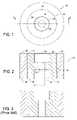
- FIG. 1is a top view of a portion of a double cavity heading die in accordance with the present invention.
- FIG. 2is a cross-sectional view of the heading die in accordance with the present invention, taken along the line 2 — 2 of FIG. 1 .
- FIG. 3is a cross-sectional view showing the construction of a heading die as taught by the prior art.
- the heading die 10comprises a tubular support ring 12 , preferably made from a hardened steel, such as H-13 tool steel, with a hardness of 45–50 Rc.
- a cylindrical insert 14 made of a suitable grade of tungsten carbideis received with the support ring 12 . More specifically, the insert 14 has an outer diameter of a size that will create a “press-fit” with the support ring 12 , ideally a class FH3 interference fit between the insert 14 and support ring 12 .
- the insert 14has opposing upper and lower end surfaces 16 , 18 that fit flush with the associated end surfaces 26 , 28 of the support ring 12 .
- the insert 14may have certain internal geometry preformed, as is known in the industry, to save on material costs and minimize subsequent machining, as described in the following paragraphs.
- the insert 14undergoes a suitable machining process to create an axial bore 20 that extends entirely through the length if the insert 14 .
- a first heading cavity 22is then machined in the upper end surface 16 of the insert 14 . As illustrated in the drawing, the first heading cavity 22 is concentric with the axial bore 20 , so that both the first cavity 22 and axial bore 20 are concentric with the outer diameter 30 of the insert 14 .
- the heading die 10is inverted in the during the machining process, so that the lower end surface 18 of the insert 14 is accessible for the final machining operation.
- a second heading cavity 24is machined in the lower end surface 18 of the insert 14 .
- the second heading cavity 24is concentric with the axial bore 20 and the outer diameter 30 of the insert 14 . It is generally desirable for the second heading cavity 24 to have the same geometry as the first heading cavity 22 to facilitate maximum utility during the manufacturing process, as described in more detail below.
- the heading die 10is suitable for use in a cold or hot forging metalworking process wherein a metal rod or sleeve used to form a part having an elongated body portion 32 and an enlarged head portion 34 , as shown in FIG. 2 .
- the heading die 10is simply inverted in the forging press to expose the lower end surface of the insert 14 , thereby making the second heading cavity 24 available for use.
- the heading die 10is capable of producing essentially twice as many parts as the prior art heading dies.
Landscapes
- Engineering & Computer Science (AREA)
- Mechanical Engineering (AREA)
- Forging (AREA)
Abstract
Description
Claims (5)
Priority Applications (1)
| Application Number | Priority Date | Filing Date | Title |
|---|---|---|---|
| US10/895,462US7104109B2 (en) | 2003-05-08 | 2003-05-08 | Double-cavity heading die |
Applications Claiming Priority (1)
| Application Number | Priority Date | Filing Date | Title |
|---|---|---|---|
| US10/895,462US7104109B2 (en) | 2003-05-08 | 2003-05-08 | Double-cavity heading die |
Publications (2)
| Publication Number | Publication Date |
|---|---|
| US20060123877A1 US20060123877A1 (en) | 2006-06-15 |
| US7104109B2true US7104109B2 (en) | 2006-09-12 |
Family
ID=36582249
Family Applications (1)
| Application Number | Title | Priority Date | Filing Date |
|---|---|---|---|
| US10/895,462Expired - Fee RelatedUS7104109B2 (en) | 2003-05-08 | 2003-05-08 | Double-cavity heading die |
Country Status (1)
| Country | Link |
|---|---|
| US (1) | US7104109B2 (en) |
Cited By (3)
| Publication number | Priority date | Publication date | Assignee | Title |
|---|---|---|---|---|
| US20070245799A1 (en)* | 2003-12-17 | 2007-10-25 | Showa Denko K.K. | Method for Producing Forging Die, Forging Die and Forged Article |
| US9126258B2 (en) | 2013-02-28 | 2015-09-08 | Robert Rottinghaus | Unitary connector pin formed by two-stage cold heading die |
| US11548193B2 (en)* | 2018-05-31 | 2023-01-10 | Silgan Dispensing Systems Le Treport S.A.S. | Method for producing a guiding rod for a pump |
Families Citing this family (4)
| Publication number | Priority date | Publication date | Assignee | Title |
|---|---|---|---|---|
| CN102699253B (en)* | 2012-05-19 | 2014-11-12 | 张家港市广大机械锻造有限公司 | Mould for forging shaft coupling |
| CN104043767A (en)* | 2013-03-11 | 2014-09-17 | 大进合紧固件(昆山)有限公司 | Cold heading mold for brake caliper guide pin |
| CN104741497A (en)* | 2014-07-18 | 2015-07-01 | 杨元清 | Combined die with chamfering function |
| CN110252926A (en)* | 2019-07-29 | 2019-09-20 | 浙江联大锻压有限公司 | Valve deck forging mold |
Citations (7)
| Publication number | Priority date | Publication date | Assignee | Title |
|---|---|---|---|---|
| US1449136A (en)* | 1922-06-27 | 1923-03-20 | Frederick C Yates | Punching tool |
| US2544302A (en)* | 1945-08-30 | 1951-03-06 | Carboloy Company Inc | Heading die and method of making it |
| US2568440A (en)* | 1948-09-09 | 1951-09-18 | Nat Machinery Co | Composite die for nut machines |
| US3169257A (en)* | 1957-08-12 | 1965-02-16 | Loos & Schmidt | Process for producing nuts |
| US3191204A (en)* | 1962-09-17 | 1965-06-29 | Nat Machinery Co | Method and apparatus for forming socket-head cap-screw blanks |
| US3937053A (en)* | 1974-08-27 | 1976-02-10 | Mototsugu Akamatsu | Forming die structure |
| US4094185A (en)* | 1977-07-05 | 1978-06-13 | Procor Limited | Double-ended heading punch |
- 2003
- 2003-05-08USUS10/895,462patent/US7104109B2/ennot_activeExpired - Fee Related
Patent Citations (7)
| Publication number | Priority date | Publication date | Assignee | Title |
|---|---|---|---|---|
| US1449136A (en)* | 1922-06-27 | 1923-03-20 | Frederick C Yates | Punching tool |
| US2544302A (en)* | 1945-08-30 | 1951-03-06 | Carboloy Company Inc | Heading die and method of making it |
| US2568440A (en)* | 1948-09-09 | 1951-09-18 | Nat Machinery Co | Composite die for nut machines |
| US3169257A (en)* | 1957-08-12 | 1965-02-16 | Loos & Schmidt | Process for producing nuts |
| US3191204A (en)* | 1962-09-17 | 1965-06-29 | Nat Machinery Co | Method and apparatus for forming socket-head cap-screw blanks |
| US3937053A (en)* | 1974-08-27 | 1976-02-10 | Mototsugu Akamatsu | Forming die structure |
| US4094185A (en)* | 1977-07-05 | 1978-06-13 | Procor Limited | Double-ended heading punch |
Cited By (4)
| Publication number | Priority date | Publication date | Assignee | Title |
|---|---|---|---|---|
| US20070245799A1 (en)* | 2003-12-17 | 2007-10-25 | Showa Denko K.K. | Method for Producing Forging Die, Forging Die and Forged Article |
| US7930954B2 (en)* | 2003-12-17 | 2011-04-26 | Showa Denko K.K. | Method for producing forging die, forging die and forged article |
| US9126258B2 (en) | 2013-02-28 | 2015-09-08 | Robert Rottinghaus | Unitary connector pin formed by two-stage cold heading die |
| US11548193B2 (en)* | 2018-05-31 | 2023-01-10 | Silgan Dispensing Systems Le Treport S.A.S. | Method for producing a guiding rod for a pump |
Also Published As
| Publication number | Publication date |
|---|---|
| US20060123877A1 (en) | 2006-06-15 |
Similar Documents
| Publication | Publication Date | Title |
|---|---|---|
| JP4147704B2 (en) | Manufacturing method of metal shell for spark plug | |
| US4061013A (en) | Method of forming socket wrenches | |
| EP1972395A2 (en) | Apparatus and method for reducing a hollow rack end diameter and hollow rack thus obtained | |
| JP4823367B2 (en) | Method for forming member having undercut portion | |
| US20070214639A1 (en) | Roller follower assembly | |
| US7588834B2 (en) | Trimless forged products and method | |
| US6151948A (en) | Methods and apparatuses for producing complex-shaped metal parts by forging | |
| US7104109B2 (en) | Double-cavity heading die | |
| US7284520B2 (en) | Valve lifter body and method of manufacture | |
| JP4005507B2 (en) | How to make a ball joint casing | |
| KR20030080982A (en) | Method of manufacturing a poppet valve | |
| US7207302B2 (en) | Valve lifter body | |
| US7069891B2 (en) | Valve operating assembly and method of manufacturing | |
| EP0786307A1 (en) | Spool valve and process for manufacturing the same | |
| US7273026B2 (en) | Roller follower body | |
| JPH0890135A (en) | Joint metal tool and manufacture of this half-made product | |
| RU2254199C1 (en) | Method for making self-locking nuts blanks with nylon ring and flange | |
| US6792786B2 (en) | Fabrication method of metal shell of spark plug | |
| RU2095185C1 (en) | Spherical finger manufacture method | |
| US7293540B2 (en) | Valve operating assembly and method of manufacturing | |
| US3897616A (en) | Method of manufacturing spherical bearings | |
| CN203390140U (en) | Cold-heading and hole-shrinkage mould | |
| JP2777997B2 (en) | Method for manufacturing shaft-shaped part having spherical head | |
| RU2185916C2 (en) | Method for making flanged sleeve | |
| US3503123A (en) | Method of making a fitting |
Legal Events
| Date | Code | Title | Description |
|---|---|---|---|
| AS | Assignment | Owner name:JP MORGAN CHASE BANK, NEW YORK Free format text:SUPPLEMENTAL PATENT SECURITY AGREEMENT;ASSIGNORS:UNILOY MILACRON INC.;D-M-E COMPANY;REEL/FRAME:016361/0605 Effective date:20050609 | |
| AS | Assignment | Owner name:U.S. BANK NATIONAL ASSOCIATION, OHIO Free format text:SECURITY AGREEMENT;ASSIGNOR:D-M-E COMPANY;REEL/FRAME:016294/0020 Effective date:20050718 | |
| AS | Assignment | Owner name:GENERAL ELECTRIC CAPITAL CORPORATION, AS AGENT, CO Free format text:SECURITY AGREEMENT;ASSIGNORS:MILACRON INC.;D-M-E U.S.A. INC.;MILACRON INDUSTRIAL PRODUCTS, INC.;AND OTHERS;REEL/FRAME:018688/0070 Effective date:20061219 Owner name:GENERAL ELECTRIC CAPITAL CORPORATION, AS AGENT,CON Free format text:SECURITY AGREEMENT;ASSIGNORS:MILACRON INC.;D-M-E U.S.A. INC.;MILACRON INDUSTRIAL PRODUCTS, INC.;AND OTHERS;REEL/FRAME:018688/0070 Effective date:20061219 Owner name:UNILOY MILACRON INC.,MICHIGAN Free format text:RELEASE BY SECURED PARTY;ASSIGNOR:JPMORGAN CHASE BANK, N.A.;REEL/FRAME:018688/0001 Effective date:20061219 Owner name:OAK INTERNATIONAL, INC.,MICHIGAN Free format text:RELEASE BY SECURED PARTY;ASSIGNOR:JPMORGAN CHASE BANK, N.A.;REEL/FRAME:018688/0001 Effective date:20061219 Owner name:MILACRON INDUSTRIAL PRODUCTS, INC.,MICHIGAN Free format text:RELEASE BY SECURED PARTY;ASSIGNOR:JPMORGAN CHASE BANK, N.A.;REEL/FRAME:018688/0001 Effective date:20061219 Owner name:D-M-E COMPANY,MICHIGAN Free format text:RELEASE BY SECURED PARTY;ASSIGNOR:JPMORGAN CHASE BANK, N.A.;REEL/FRAME:018688/0001 Effective date:20061219 Owner name:MILACRON INC.,OHIO Free format text:RELEASE BY SECURED PARTY;ASSIGNOR:JPMORGAN CHASE BANK, N.A.;REEL/FRAME:018688/0001 Effective date:20061219 Owner name:D-M-E U.S.A. INC,MICHIGAN Free format text:RELEASE BY SECURED PARTY;ASSIGNOR:JPMORGAN CHASE BANK, N.A.;REEL/FRAME:018688/0001 Effective date:20061219 Owner name:UNILOY MILACRON U.S.A. INC.,MICHIGAN Free format text:RELEASE BY SECURED PARTY;ASSIGNOR:JPMORGAN CHASE BANK, N.A.;REEL/FRAME:018688/0001 Effective date:20061219 Owner name:MILACRON INC., OHIO Free format text:RELEASE BY SECURED PARTY;ASSIGNOR:JPMORGAN CHASE BANK, N.A.;REEL/FRAME:018688/0001 Effective date:20061219 Owner name:D-M-E U.S.A. INC, MICHIGAN Free format text:RELEASE BY SECURED PARTY;ASSIGNOR:JPMORGAN CHASE BANK, N.A.;REEL/FRAME:018688/0001 Effective date:20061219 Owner name:OAK INTERNATIONAL, INC., MICHIGAN Free format text:RELEASE BY SECURED PARTY;ASSIGNOR:JPMORGAN CHASE BANK, N.A.;REEL/FRAME:018688/0001 Effective date:20061219 Owner name:MILACRON INDUSTRIAL PRODUCTS, INC., MICHIGAN Free format text:RELEASE BY SECURED PARTY;ASSIGNOR:JPMORGAN CHASE BANK, N.A.;REEL/FRAME:018688/0001 Effective date:20061219 Owner name:D-M-E COMPANY, MICHIGAN Free format text:RELEASE BY SECURED PARTY;ASSIGNOR:JPMORGAN CHASE BANK, N.A.;REEL/FRAME:018688/0001 Effective date:20061219 Owner name:UNILOY MILACRON U.S.A. INC., MICHIGAN Free format text:RELEASE BY SECURED PARTY;ASSIGNOR:JPMORGAN CHASE BANK, N.A.;REEL/FRAME:018688/0001 Effective date:20061219 Owner name:UNILOY MILACRON INC., MICHIGAN Free format text:RELEASE BY SECURED PARTY;ASSIGNOR:JPMORGAN CHASE BANK, N.A.;REEL/FRAME:018688/0001 Effective date:20061219 | |
| AS | Assignment | Owner name:GENERAL ELECTRIC CAPITAL CORPORATION, AS AGENT, CO Free format text:SECURITY AGREEMENT;ASSIGNORS:MILACRON INC;CIMCOOL INDUSTRIAL PRODUCTS INC.;MILACRON MARKETING COMPANY;AND OTHERS;REEL/FRAME:022427/0080 Effective date:20090311 Owner name:GENERAL ELECTRIC CAPITAL CORPORATION, AS AGENT,CON Free format text:SECURITY AGREEMENT;ASSIGNORS:MILACRON INC;CIMCOOL INDUSTRIAL PRODUCTS INC.;MILACRON MARKETING COMPANY;AND OTHERS;REEL/FRAME:022427/0080 Effective date:20090311 | |
| AS | Assignment | Owner name:D-M-E COMPANY, INC., MICHIGAN Free format text:RELEASE BY SECURED PARTY;ASSIGNOR:U.S. BANK NATIONAL ASSOCIATION, AS TRUSTEE AND COLLATERAL AGENT;REEL/FRAME:023134/0432 Effective date:20090821 Owner name:D-M-E U.S.A. INC., MICHIGAN Free format text:RELEASE BY SECURED PARTY;ASSIGNOR:U.S. BANK NATIONAL ASSOCIATION, AS TRUSTEE AND COLLATERAL AGENT;REEL/FRAME:023134/0432 Effective date:20090821 Owner name:MILACRON INC., OHIO Free format text:RELEASE BY SECURED PARTY;ASSIGNOR:U.S. BANK NATIONAL ASSOCIATION, AS TRUSTEE AND COLLATERAL AGENT;REEL/FRAME:023134/0432 Effective date:20090821 Owner name:MILACRON INDUSTRIAL PRODUCTS INC., MICHIGAN Free format text:RELEASE BY SECURED PARTY;ASSIGNOR:U.S. BANK NATIONAL ASSOCIATION, AS TRUSTEE AND COLLATERAL AGENT;REEL/FRAME:023134/0432 Effective date:20090821 Owner name:OAK INTERNATIONAL, INC., MICHIGAN Free format text:RELEASE BY SECURED PARTY;ASSIGNOR:U.S. BANK NATIONAL ASSOCIATION, AS TRUSTEE AND COLLATERAL AGENT;REEL/FRAME:023134/0432 Effective date:20090821 Owner name:UNILOY MILACRON INC., MICHIGAN Free format text:RELEASE BY SECURED PARTY;ASSIGNOR:U.S. BANK NATIONAL ASSOCIATION, AS TRUSTEE AND COLLATERAL AGENT;REEL/FRAME:023134/0432 Effective date:20090821 Owner name:UNILOY MILACRON U.S.A. INC., MICHIGAN Free format text:RELEASE BY SECURED PARTY;ASSIGNOR:U.S. BANK NATIONAL ASSOCIATION, AS TRUSTEE AND COLLATERAL AGENT;REEL/FRAME:023134/0432 Effective date:20090821 Owner name:D-M-E COMPANY, INC.,MICHIGAN Free format text:RELEASE BY SECURED PARTY;ASSIGNOR:U.S. BANK NATIONAL ASSOCIATION, AS TRUSTEE AND COLLATERAL AGENT;REEL/FRAME:023134/0432 Effective date:20090821 Owner name:D-M-E U.S.A. INC.,MICHIGAN Free format text:RELEASE BY SECURED PARTY;ASSIGNOR:U.S. BANK NATIONAL ASSOCIATION, AS TRUSTEE AND COLLATERAL AGENT;REEL/FRAME:023134/0432 Effective date:20090821 Owner name:MILACRON INC.,OHIO Free format text:RELEASE BY SECURED PARTY;ASSIGNOR:U.S. BANK NATIONAL ASSOCIATION, AS TRUSTEE AND COLLATERAL AGENT;REEL/FRAME:023134/0432 Effective date:20090821 Owner name:MILACRON INDUSTRIAL PRODUCTS INC.,MICHIGAN Free format text:RELEASE BY SECURED PARTY;ASSIGNOR:U.S. BANK NATIONAL ASSOCIATION, AS TRUSTEE AND COLLATERAL AGENT;REEL/FRAME:023134/0432 Effective date:20090821 Owner name:OAK INTERNATIONAL, INC.,MICHIGAN Free format text:RELEASE BY SECURED PARTY;ASSIGNOR:U.S. BANK NATIONAL ASSOCIATION, AS TRUSTEE AND COLLATERAL AGENT;REEL/FRAME:023134/0432 Effective date:20090821 Owner name:UNILOY MILACRON INC.,MICHIGAN Free format text:RELEASE BY SECURED PARTY;ASSIGNOR:U.S. BANK NATIONAL ASSOCIATION, AS TRUSTEE AND COLLATERAL AGENT;REEL/FRAME:023134/0432 Effective date:20090821 Owner name:UNILOY MILACRON U.S.A. INC.,MICHIGAN Free format text:RELEASE BY SECURED PARTY;ASSIGNOR:U.S. BANK NATIONAL ASSOCIATION, AS TRUSTEE AND COLLATERAL AGENT;REEL/FRAME:023134/0432 Effective date:20090821 | |
| AS | Assignment | Owner name:WELLS FARGO FOOTHILL, LLC, AS AGENT, GEORGIA Free format text:SECURITY AGREEMENT;ASSIGNORS:MILACRON LLC;DME COMPANY LLC;REEL/FRAME:023134/0669 Effective date:20090821 Owner name:WELLS FARGO FOOTHILL, LLC, AS AGENT,GEORGIA Free format text:SECURITY AGREEMENT;ASSIGNORS:MILACRON LLC;DME COMPANY LLC;REEL/FRAME:023134/0669 Effective date:20090821 | |
| AS | Assignment | Owner name:DME COMPANY LLC, MICHIGAN Free format text:ASSIGNMENT OF ASSIGNORS INTEREST;ASSIGNOR:D-M-E COMPANY;REEL/FRAME:023163/0620 Effective date:20090818 Owner name:DME COMPANY LLC,MICHIGAN Free format text:ASSIGNMENT OF ASSIGNORS INTEREST;ASSIGNOR:D-M-E COMPANY;REEL/FRAME:023163/0620 Effective date:20090818 | |
| AS | Assignment | Owner name:MILACRON INC., OHIO Free format text:RELEASE BY SECURED PARTY;ASSIGNOR:GENERAL ELECTRIC CAPITAL CORPORATION, AS AGENT;REEL/FRAME:023180/0690 Effective date:20090821 Owner name:MILACRON MARKETING COMPANY, OHIO Free format text:RELEASE BY SECURED PARTY;ASSIGNOR:GENERAL ELECTRIC CAPITAL CORPORATION, AS AGENT;REEL/FRAME:023180/0690 Effective date:20090821 Owner name:MILACRON PLASTICS TECHNOLOGIES GROUP INC., OHIO Free format text:RELEASE BY SECURED PARTY;ASSIGNOR:GENERAL ELECTRIC CAPITAL CORPORATION, AS AGENT;REEL/FRAME:023180/0690 Effective date:20090821 Owner name:D-M-E COMPANY, INC., MICHIGAN Free format text:RELEASE BY SECURED PARTY;ASSIGNOR:GENERAL ELECTRIC CAPITAL CORPORATION, AS AGENT;REEL/FRAME:023180/0690 Effective date:20090821 Owner name:CIMCOOL INDUSTRIAL PRODUCTS INC., OHIO Free format text:RELEASE BY SECURED PARTY;ASSIGNOR:GENERAL ELECTRIC CAPITAL CORPORATION, AS AGENT;REEL/FRAME:023180/0690 Effective date:20090821 Owner name:MILACRON INC.,OHIO Free format text:RELEASE BY SECURED PARTY;ASSIGNOR:GENERAL ELECTRIC CAPITAL CORPORATION, AS AGENT;REEL/FRAME:023180/0690 Effective date:20090821 Owner name:MILACRON MARKETING COMPANY,OHIO Free format text:RELEASE BY SECURED PARTY;ASSIGNOR:GENERAL ELECTRIC CAPITAL CORPORATION, AS AGENT;REEL/FRAME:023180/0690 Effective date:20090821 Owner name:MILACRON PLASTICS TECHNOLOGIES GROUP INC.,OHIO Free format text:RELEASE BY SECURED PARTY;ASSIGNOR:GENERAL ELECTRIC CAPITAL CORPORATION, AS AGENT;REEL/FRAME:023180/0690 Effective date:20090821 Owner name:D-M-E COMPANY, INC.,MICHIGAN Free format text:RELEASE BY SECURED PARTY;ASSIGNOR:GENERAL ELECTRIC CAPITAL CORPORATION, AS AGENT;REEL/FRAME:023180/0690 Effective date:20090821 Owner name:CIMCOOL INDUSTRIAL PRODUCTS INC.,OHIO Free format text:RELEASE BY SECURED PARTY;ASSIGNOR:GENERAL ELECTRIC CAPITAL CORPORATION, AS AGENT;REEL/FRAME:023180/0690 Effective date:20090821 | |
| AS | Assignment | Owner name:THE BANK OF NEW YORK MELLON, TEXAS Free format text:SECOND LIEN PATENT SECURITY AGREEMENT;ASSIGNORS:MILACRON LLC;DME COMPANY LLC;REEL/FRAME:023449/0926 Effective date:20091021 Owner name:THE BANK OF NEW YORK MELLON,TEXAS Free format text:SECOND LIEN PATENT SECURITY AGREEMENT;ASSIGNORS:MILACRON LLC;DME COMPANY LLC;REEL/FRAME:023449/0926 Effective date:20091021 | |
| REMI | Maintenance fee reminder mailed | ||
| LAPS | Lapse for failure to pay maintenance fees | ||
| STCH | Information on status: patent discontinuation | Free format text:PATENT EXPIRED DUE TO NONPAYMENT OF MAINTENANCE FEES UNDER 37 CFR 1.362 | |
| FP | Lapsed due to failure to pay maintenance fee | Effective date:20100912 | |
| AS | Assignment | Owner name:DME COMPANY LLC, MICHIGAN Free format text:SECURITY AGREEMENT;ASSIGNOR:THE BANK OF NEW YORK MELLON;REEL/FRAME:026346/0680 Effective date:20110506 | |
| AS | Assignment | Owner name:DME COMPANY LLC, MICHIGAN Free format text:RELEASE BY SECURED PARTY;ASSIGNOR:WELLS FARGO CAPITAL FINANCE LLC;REEL/FRAME:028129/0027 Effective date:20120430 | |
| AS | Assignment | Owner name:DME COMPANY LLC, MICHIGAN Free format text:PATENT RELEASE;ASSIGNOR:BANK OF AMERICA, N.A., AS ADMINISTRATIVE AGENT;REEL/FRAME:028153/0392 Effective date:20120430 |