US7103260B1 - Video editing system - Google Patents
Video editing systemDownload PDFInfo
- Publication number
- US7103260B1 US7103260B1US09/537,986US53798600AUS7103260B1US 7103260 B1US7103260 B1US 7103260B1US 53798600 AUS53798600 AUS 53798600AUS 7103260 B1US7103260 B1US 7103260B1
- Authority
- US
- United States
- Prior art keywords
- data
- frame
- rate
- output
- store
- Prior art date
- Legal status (The legal status is an assumption and is not a legal conclusion. Google has not performed a legal analysis and makes no representation as to the accuracy of the status listed.)
- Expired - Lifetime
Links
- 238000012545processingMethods0.000claimsabstractdescription9
- 239000000872bufferSubstances0.000claimsdescription18
- 238000003860storageMethods0.000claimsdescription10
- 230000004044responseEffects0.000claimsdescription8
- 238000000034methodMethods0.000claimsdescription6
- 238000004513sizingMethods0.000claimsdescription6
- 230000008569processEffects0.000claimsdescription4
- 238000013459approachMethods0.000description5
- 238000006243chemical reactionMethods0.000description4
- 230000000694effectsEffects0.000description3
- 238000005070samplingMethods0.000description3
- 241001422033ThestylusSpecies0.000description2
- 230000008859changeEffects0.000description2
- 238000013500data storageMethods0.000description2
- 238000010586diagramMethods0.000description2
- 238000009826distributionMethods0.000description2
- 238000004519manufacturing processMethods0.000description2
- 239000000463materialSubstances0.000description2
- 230000004048modificationEffects0.000description2
- 238000012986modificationMethods0.000description2
- 230000005236sound signalEffects0.000description2
- 230000001360synchronised effectEffects0.000description2
- 230000009471actionEffects0.000description1
- 235000014121butterNutrition0.000description1
- 230000001667episodic effectEffects0.000description1
- 238000007781pre-processingMethods0.000description1
- 230000009467reductionEffects0.000description1
- 238000012552reviewMethods0.000description1
- 238000000926separation methodMethods0.000description1
Images


Classifications
- H—ELECTRICITY
- H04—ELECTRIC COMMUNICATION TECHNIQUE
- H04N—PICTORIAL COMMUNICATION, e.g. TELEVISION
- H04N7/00—Television systems
- H04N7/01—Conversion of standards, e.g. involving analogue television standards or digital television standards processed at pixel level
- H04N7/0105—Conversion of standards, e.g. involving analogue television standards or digital television standards processed at pixel level using a storage device with different write and read speed
- H—ELECTRICITY
- H04—ELECTRIC COMMUNICATION TECHNIQUE
- H04N—PICTORIAL COMMUNICATION, e.g. TELEVISION
- H04N7/00—Television systems
- H04N7/01—Conversion of standards, e.g. involving analogue television standards or digital television standards processed at pixel level
- H04N7/0112—Conversion of standards, e.g. involving analogue television standards or digital television standards processed at pixel level one of the standards corresponding to a cinematograph film standard
Definitions
- each television framecomprises two interleaved fields.
- One fieldcomprises all the odd numbered lines in a frame and the other field comprises all the even numbered lines in a frame.
- the edited clipis output at 24 frames per second to circuitry which converts the 625 lines to 525 lines and converts the 24 frames per second into 30 frames per second using 3:2 pull down techniques.
- the resulting videois recorded on to standard 30/525 tape for subsequent playback on standard NTSC equipment.
- Using this approachalso requires the audio to be resampled.
- the audio signalis normally sampled at a rate of 48 KHz, but when the tape speed is reduced from 25 to 24 frames per second there is a corresponding reduction of the audio sampling rate to 46 KHz.
- the audio signalis therefore reclocked (without pitch change) from the incorrect 46 KHz sampling rate to the correct 48 KHz sampling rate.
- Off-line non-linear editing systemsare available which are capable of manipulating 30 frames per second video generated by way of 3:2 pull down.
- One such systemis arranged to remove the additional fields generated by the 3:2 pull down operation and to store only the two fields that make up each frame.
- the output of such a systemis put through an internal 3:2 conversion so that the user of the system views the output at 60 fields per second.
- the systemproduces a standard 30 frames per second edit decision list (EDL).
- Another approach to overcoming the aforementioned problemsis to carry out an edit using such an off-line non-linear editing system in order to make an EDL which is then conformed at either 24 frames per second or 25 frames per second. Either frame rate is acceptable, the important thing is that the edit occurs in the right place.
- a modified VTRis used to play back video rushes at 24 frames per second to enable 30 frame per second dubs to be produced (via 3:2 pull down).
- the 30 frame per second dubsare taken into an off-line non-linear editing system, as aforementioned. Editing decisions are made using the system and a standard 30 frames per second EDL is produced.
- the EDL thus producedis fettled to produce a 25 frames per second EDL which is then used to conform the high-quality 625 rushes in a tape based auto-conform suite to produce the 625 master tape, which is only correctly paced when played at 24 frames per second.
- the aforementioned modified VTRmay also be used to play back a 25/625 master at 24 frames per second in order to enable the production (via 3:2 pull down) of 30/525 distribution copies from the 25/625 master.
- the present inventionaims to overcome or at least reduce the above and related problems.
- an editing system for moving imagescomprising: a frame-random access store for storing image data representing a sequence of image frames which together form a moving image, the store storing data such that the frames can be accessed in a random order; an input circuit for receiving from a source data representing one or more sequences of image frames captured at a first frame rate, the data being received at an input data rate and representing each frame in a sequence as a first multiplicity of image lines which together form the image frame, and for transferring the data to the frame-random access store; an editing processor for editing data read from the store at a processed data rate to produce data representing an edited sequence of image frames; and an output circuit for outputting edited data representing an edited sequence of image frames at a second frame rate, the data being output at an output data rate and representing each frame in the edited sequence as a second multiplicity of image lines which together form the image frame.
- the inventionalso provides an editing system in which image data representing an initial moving image input in a first format at a corresponding rate is stored in a store and is manipulated to produce image data representing an edited moving image for output in a second format at a corresponding data rate, the system being arranged such that processing is effected at a data rate which is variable and determines the second data rate.
- FIG. 1is a schematic functional block diagram of a system embodying the invention
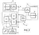
- FIG. 2is a schematic functional block diagram of another system embodying the invention.
- FIG. 1 of the accompanying drawingsthere is shown a video editing system 1 comprising a frame-random access data store (represented by the broken lines 2 ) connected to receive video data via an input butter 3 (suitably a FIFO buffer) from one or more video sources, for example a telecine 4 or a video tape recorder (VTR) 5 .
- a telecine 4 or the VTR 5are standard video data sources designed to supply data representing video frames at a predetermined frame rate, with each frame comprising a predetermined number of lines per frame.
- Movie camerasare designed to capture movie images on film at a rate of 24 frames per second.
- the telecine 4is designed to scan each frame of the film clip into a predetermined number of lines and to output that data in the format of 25 frames per second, 2 interleaved fields per frame and 625 lines per frame. Thus the telecine 4 generates video data representing image frames from a film clip 6 .
- the VTR 5is also designed to output video data in the format of 25 frames per second with two interleaved fields together comprising a total of 625 lines per frame. This will be referred to herein as the 25/625 format.
- Both the telecine 4 and the VCR 5are standard pieces of equipment and need not be described in any greater detail herein.
- FIG. 1shows the telecine 4 connected to the VTR 5 , because this is the normal route by which data would be supplied from a telecine to an editing system. There is however no technical reason why the telecine 4 should not be connected directly to the input buffer 3 to input data to the frame-random access data store 2 .
- the frame-random access store 2is a large data storage device capable of storing data representing video frames in frame-random access order. That is to say, the data representing any frame stored in the store can be accessed as quickly as the data representing any other frame in the store.
- the storecomprises a number of disk stores 7 connected to RAM or other buffers 8 and to data interfaces and highways which together enable video data to be output therefrom at a rate (for example the 25/625 rate) determined by a system clock 10 .
- the system clock 10is arranged to generate a clocking signal representing the frame rate (e.g. 25 per second) of the video data.
- the store 2may also comprise a sizing circuit 11 for changing the size of frames of data, for example, from 625 lines to 525 lines per frame.
- the sizing circuit 11comprises an interpolator and is connected to change the size of data output from the disk stores 7 before the data is input to the RAM buffers 8 .
- the store 2may be based on the data storage apparatus described in our British Patent Application No. 9226199.9 published as GB-A-2273584 and corresponding U.S. Pat. No. 5,765,186, the teachings of which are incorporated herein by reference.
- the system 1also comprises an edit and control processor 12 connected to the frame random access store 2 to enable editing and processing of the data stored therein. Operation of the edit and control processor 12 is controlled by a user by way of a stylus and touch tablet 13 or other user operable input device which generates control signals in response to manipulation thereof.
- the edit and control processor 12is in itself known and is described, for example, in British Patent Application No. 9205503.7 published as GB-A-2266037 and corresponding U.S. Pat. No. 5,808,628, the teachings of which are incorporated herein by reference. Together the store 2 and the processor 12 enable video data to be combined to produce data representing an edited and/or processed clip from the initial data input to the store 2 from the telecine 4 , the VTR 5 , or other video data sources (not shown).
- the store 2has associated with it an output buffer 14 which is arranged to receive video data from the store 2 at the rate determined by the system clock 10 .
- the buffer 4is connected to a monitor 15 to enable (among other things) an edited video clip to be previewed, and to a video tape recorder (VTR) 16 or other bulk storage device to enable an edited video clip to be stored off-line once the user is satisfied with the result of the editing performed using the system 1 .
- VTRvideo tape recorder
- the system 1is operable in a number of different modes including an input mode when the system clock 10 is set at one rate and a preview mode when the system clock is set at another rate.
- the system clock 10When operating in the input mode the system clock 10 is arranged to generate clocking signals appropriate to the 25/625 rate at which data is input from the VTR 5 .
- the dataAs data is input from the VTR to the store 2 , the data may also be output via the output buffer 14 for display of the image represented thereby on the monitor 15 .
- the dynamics of the imageare not correct when displayed in this mode because 25 frames are displayed in a period when only 24 frames should be displayed.
- the system clock 10is arranged to generate clocking signals appropriate to the display of data on the monitor 15 at a rate of 24 frames per second and 625 lines per frame (24/625). This corresponds to the frame rate at which the original images were captured on film and thus the dynamics of the scene are accurately represented.
- the monitor 15 shown in FIG. 1is a standard 25 frames per second monitor. Despite being designed for a frame rate of 25 frames per second, most, if not all, monitors currently available on the market can be adjusted (by varying the vertical sync signal) to display frames at a rate of 24 per second. Such an adjustment may be made manually by the operator or automatically by the system 1 depending on the particular monitor used.
- Editing operationsare effected at the 24 frames per second rate by the edit and control processor 12 in response to editor (user) manipulation of the stylus and touch tablet 13 with data movements within the system all occurring at a rate corresponding to the 24/625 rate.
- editoruser
- the editoris able to review the dynamics in the moving image at the correct speed. Audio is also adjusted to get proper synchronisation between movement and sound.
- the datamay be output at the 25/625 rate for storage directly on the VTR 16 or other bulk storage device in a form suitable to, for example, the European PAL format.
- the system clockwould be set to generate clocking signals appropriate to the 25/625 rate of the PAL standard.
- the system clockwould be set to generate clocking signals appropriate to the 24/625 rate.
- the store 2would be arranged so that data is transferred from the disks 7 to RAM 8 via the size circuit 11 .
- the size circuit 11would be arranged to convert the 625 lines to 525 lines.
- Data at a rate of 24/525would be output from the output buffer 14 to the VTR 16 or other bulk store via a 3:2 pull down circuit (not shown).
- the data stored in the VTRwould be stored at a 30/525 rate which corresponds to the rate for NTSC.
- Such an arrangement with a 3:2 pull down circuitcould also be used during editing to allow the editor to preview the effects of an edit at 60 fields per second.
- the 25/625 monitor 15would be replaced with a 30/525 monitor, thereby enabling the editor to see the edit as a 30/525 output.
- Such a conversioncould equally be applied to a 25 frames per second output or a 30 frames per second output.
- the inventionis not limited to the 24 frames per second of movies, the frames per second of PAL and the 30 frames per second of NTSC, or to the 625 lines of PAL and 525 lines of NTSC.
- Other standardscan be achieved using the system 1 shown in FIG. 1 by the appropriate modification of clocks and data rates.
- FIG. 1whilst able to receive, manipulate and output data at different rates, is nevertheless restricted in that at any given time only one clock is running. Thus data cannot simultaneously be input at one data rate and output at another different data rate.
- FIG. 2 of the accompanying drawingsrepresents a system which addresses this and related issues.
- FIG. 2there is shown a system 21 having in common with the system 1 shown in FIG. 1 many of the same elements.
- elements which are equivalent to those of FIG. 1have been given the same reference numeral.
- the elements of FIG. 2will only be described insofar as they differ from the equivalent elements of FIG. 1 .
- Video signalsare input to the system via an input decoder 22 .
- the signalsmay be supplied from any suitable source (not shown) including a VTR, a video camera, a frame random access store, etc. It follows that the video signals may represent video images in any one of the wide range of video standards that have now been defined. Thus, in addition to the aforementioned 25/625 PAL and 30/525 NTSC standards, the signals may represent video at a high definition (HD) standard, including the draft SMPTE standard of 1080 lines per frame and 24 frames per second (24/1080) and ITU-R 60/1125 and 50/1250 production standards.
- the decoder 22is arranged to remove sync signals and the like from the incoming signals and to convert the signals into data representing lines of pixels.
- the size of frames and the frame rateare not varied by the decoder 22 .
- Operation of the decoder 22is “genlocked” i.e. synchronised, to the rate of the incoming signals from the source.
- a RAM buffer 23is connected between the decoder 22 and an asynchronous system bus 24 . Since the bus 24 is asynchronous it is necessary to ensure that the RAM buffer 23 is large enough that none of the incoming data is lost before being transferred on to the system bus. Thus, the RAM buffer 23 provides an interface between the genlocked input operations within box 25 and the asynchronous transfers of data over the system bus 24 .
- the system 21may also comprise a processor 26 for pre-processing the data before it is transferred to the store 2 or to process the data as it is read from the store 2 , the processor 26 is shown as a separate unit but may in fact form part of the edit and control processor 12 and thus be responsive to editor (user) manipulation of the stylus and touch tablet device.
- An output RAM buffer 27is also connected to receive data from the system bus 24 .
- the output RAM buffer 27is connected to an encoder 28 which is genlocked to output data at an output data rate.
- the encoder 28may be connected to output signals to any suitable device (not shown) including a VTR, a monitor or a frame-random access store. It follows that the output data rate may be the same as the input data rate, or the frame and/or line rate may be different (larger or smaller) than the input rate.
- the aspect ratios of the images represented by the input and output datamay be the same or may differ from each other.
- the output RAM buffer 27 and the encoder 28work together so that operations within the box 29 are genlocked to the output device. Signals from the encoder 28 may be output to a monitor and/or bulk store (not shown) for display and/or storage thereat at the output data rate.
- the system 21 shown in FIG. 2thus enables input material to be stored “native” in the store 2 , i.e. at its original frame and line rates, to be freely edited with other material stored native in its own format, which may be different, and the result to be output at any desired standard by resizing each frame to the desired standard as it is output.
- This flexibilityis made possible in part by the separation of the genlocked input and output operations 25 , 29 , and in part by the provision of the sizing circuit 11 and processor 26 which are able to process data “on the fly” as it is transferred from, over and to the asynchronous system bus.
Landscapes
- Engineering & Computer Science (AREA)
- Multimedia (AREA)
- Signal Processing (AREA)
- Television Signal Processing For Recording (AREA)
- Television Systems (AREA)
- Studio Devices (AREA)
Abstract
Description
Claims (38)
Applications Claiming Priority (1)
| Application Number | Priority Date | Filing Date | Title |
|---|---|---|---|
| GB9908832AGB2349288B (en) | 1999-04-16 | 1999-04-16 | A video editing system |
Publications (1)
| Publication Number | Publication Date |
|---|---|
| US7103260B1true US7103260B1 (en) | 2006-09-05 |
Family
ID=10851750
Family Applications (1)
| Application Number | Title | Priority Date | Filing Date |
|---|---|---|---|
| US09/537,986Expired - LifetimeUS7103260B1 (en) | 1999-04-16 | 2000-03-29 | Video editing system |
Country Status (4)
| Country | Link |
|---|---|
| US (1) | US7103260B1 (en) |
| EP (1) | EP1052645A3 (en) |
| JP (1) | JP2000324453A (en) |
| GB (1) | GB2349288B (en) |
Cited By (16)
| Publication number | Priority date | Publication date | Assignee | Title |
|---|---|---|---|---|
| US20040119847A1 (en)* | 2002-08-16 | 2004-06-24 | Tsutomu Kume | Image processing apparatus, image processing method, recording medium, and program |
| US20090080509A1 (en)* | 2004-11-16 | 2009-03-26 | Masanori Itoh | Data processor |
| US20090147131A1 (en)* | 2007-12-07 | 2009-06-11 | Canon Kabushiki Kaisha | Image editing apparatus, image editing method, and storage medium storing image editing program |
| US20100195908A1 (en)* | 2009-02-02 | 2010-08-05 | Gentex Corporation | Digital image processing and systems incorporating the same |
| US20100303349A1 (en)* | 2009-05-28 | 2010-12-02 | Bechtel Jon H | Digital image processing and systems incorporating the same |
| US20110206352A1 (en)* | 2010-02-19 | 2011-08-25 | Canon Kabushiki Kaisha | Image editing apparatus and method for controlling the same, and storage medium storing program |
| US8775480B2 (en) | 2011-01-28 | 2014-07-08 | Apple Inc. | Media clip management |
| US8839110B2 (en) | 2011-02-16 | 2014-09-16 | Apple Inc. | Rate conform operation for a media-editing application |
| US9014544B2 (en) | 2012-12-19 | 2015-04-21 | Apple Inc. | User interface for retiming in a media authoring tool |
| US9041838B2 (en) | 2012-02-14 | 2015-05-26 | Gentex Corporation | High dynamic range imager system |
| US9116896B2 (en) | 2012-03-31 | 2015-08-25 | Bitcentral, Inc. | Nonlinear proxy-based editing system and method with improved media file ingestion and management |
| US9412414B2 (en) | 2011-02-16 | 2016-08-09 | Apple Inc. | Spatial conform operation for a media-editing application |
| US9769430B1 (en) | 2011-06-23 | 2017-09-19 | Gentex Corporation | Imager system with median filter and method thereof |
| US9997196B2 (en) | 2011-02-16 | 2018-06-12 | Apple Inc. | Retiming media presentations |
| US10324605B2 (en) | 2011-02-16 | 2019-06-18 | Apple Inc. | Media-editing application with novel editing tools |
| US11747972B2 (en) | 2011-02-16 | 2023-09-05 | Apple Inc. | Media-editing application with novel editing tools |
Families Citing this family (1)
| Publication number | Priority date | Publication date | Assignee | Title |
|---|---|---|---|---|
| GB2373118B (en)* | 2000-12-21 | 2005-01-19 | Quantel Ltd | Improvements in or relating to image processing systems |
Citations (13)
| Publication number | Priority date | Publication date | Assignee | Title |
|---|---|---|---|---|
| GB2220539A (en) | 1988-07-08 | 1990-01-10 | Mitsubishi Electric Corp | Scanning line converter |
| US4963995A (en)* | 1988-12-27 | 1990-10-16 | Explore Technology, Inc. | Audio/video transceiver apparatus including compression means |
| WO1991019379A1 (en) | 1990-06-01 | 1991-12-12 | Thomson Consumer Electronics, Inc. | Field synchronization system with write/read pointer control |
| GB2251755A (en) | 1991-01-08 | 1992-07-15 | Sony Broadcast & Communication | Video standards up-conversion |
| GB2255254A (en) | 1991-03-28 | 1992-10-28 | Matsushita Electric Industrial Co Ltd | Television standard conversion apparatus |
| GB2257591A (en) | 1991-07-08 | 1993-01-13 | Sony Broadcast & Communication | Video standards conversion |
| GB2260055A (en) | 1991-09-28 | 1993-03-31 | Samsung Electronics Co Ltd | Colour television signal scanning format converting apparatus |
| US5221966A (en)* | 1990-01-17 | 1993-06-22 | Avesco Plc | Video signal production from cinefilm originated material |
| WO1995009412A1 (en) | 1993-09-27 | 1995-04-06 | Honeywell Inc. | Simplified image reconstruction interface |
| US5418572A (en)* | 1992-04-29 | 1995-05-23 | Quantel Limited | Method of and apparatus for displaying images at different rates |
| GB2305801A (en) | 1995-09-29 | 1997-04-16 | Samsung Electronics Co Ltd | Image decoding apparatus having frame rate transformation function |
| US5808628A (en)* | 1992-03-13 | 1998-09-15 | Quantel Ltd. | Electronic video processing system |
| US5999220A (en)* | 1997-04-07 | 1999-12-07 | Washino; Kinya | Multi-format audio/video production system with frame-rate conversion |
Family Cites Families (2)
| Publication number | Priority date | Publication date | Assignee | Title |
|---|---|---|---|---|
| JPH0851600A (en)* | 1994-08-04 | 1996-02-20 | Sanyo Electric Co Ltd | Video signal converter |
| US6407775B1 (en)* | 1999-04-16 | 2002-06-18 | Avid Technology, Inc. | Image resizer and frame rate converter with pulldown controller |
- 1999
- 1999-04-16GBGB9908832Apatent/GB2349288B/ennot_activeExpired - Fee Related
- 2000
- 2000-03-29USUS09/537,986patent/US7103260B1/ennot_activeExpired - Lifetime
- 2000-04-14JPJP2000112833Apatent/JP2000324453A/enactivePending
- 2000-04-14EPEP00303181Apatent/EP1052645A3/ennot_activeWithdrawn
Patent Citations (13)
| Publication number | Priority date | Publication date | Assignee | Title |
|---|---|---|---|---|
| GB2220539A (en) | 1988-07-08 | 1990-01-10 | Mitsubishi Electric Corp | Scanning line converter |
| US4963995A (en)* | 1988-12-27 | 1990-10-16 | Explore Technology, Inc. | Audio/video transceiver apparatus including compression means |
| US5221966A (en)* | 1990-01-17 | 1993-06-22 | Avesco Plc | Video signal production from cinefilm originated material |
| WO1991019379A1 (en) | 1990-06-01 | 1991-12-12 | Thomson Consumer Electronics, Inc. | Field synchronization system with write/read pointer control |
| GB2251755A (en) | 1991-01-08 | 1992-07-15 | Sony Broadcast & Communication | Video standards up-conversion |
| GB2255254A (en) | 1991-03-28 | 1992-10-28 | Matsushita Electric Industrial Co Ltd | Television standard conversion apparatus |
| GB2257591A (en) | 1991-07-08 | 1993-01-13 | Sony Broadcast & Communication | Video standards conversion |
| GB2260055A (en) | 1991-09-28 | 1993-03-31 | Samsung Electronics Co Ltd | Colour television signal scanning format converting apparatus |
| US5808628A (en)* | 1992-03-13 | 1998-09-15 | Quantel Ltd. | Electronic video processing system |
| US5418572A (en)* | 1992-04-29 | 1995-05-23 | Quantel Limited | Method of and apparatus for displaying images at different rates |
| WO1995009412A1 (en) | 1993-09-27 | 1995-04-06 | Honeywell Inc. | Simplified image reconstruction interface |
| GB2305801A (en) | 1995-09-29 | 1997-04-16 | Samsung Electronics Co Ltd | Image decoding apparatus having frame rate transformation function |
| US5999220A (en)* | 1997-04-07 | 1999-12-07 | Washino; Kinya | Multi-format audio/video production system with frame-rate conversion |
Cited By (31)
| Publication number | Priority date | Publication date | Assignee | Title |
|---|---|---|---|---|
| US7411617B2 (en)* | 2002-08-16 | 2008-08-12 | Sony Corporation | Image processing apparatus, image processing method, recording medium, and program |
| US20040119847A1 (en)* | 2002-08-16 | 2004-06-24 | Tsutomu Kume | Image processing apparatus, image processing method, recording medium, and program |
| US20090080509A1 (en)* | 2004-11-16 | 2009-03-26 | Masanori Itoh | Data processor |
| US20090147131A1 (en)* | 2007-12-07 | 2009-06-11 | Canon Kabushiki Kaisha | Image editing apparatus, image editing method, and storage medium storing image editing program |
| US8866966B2 (en) | 2007-12-07 | 2014-10-21 | Canon Kabushiki Kaisha | Image editing apparatus, image editing method, and storage medium storing image editing program |
| US8577169B2 (en) | 2009-02-02 | 2013-11-05 | Gentex Corporation | Digital image processing and systems incorporating the same |
| US20100195908A1 (en)* | 2009-02-02 | 2010-08-05 | Gentex Corporation | Digital image processing and systems incorporating the same |
| US20100195901A1 (en)* | 2009-02-02 | 2010-08-05 | Andrus Jeremy C | Digital image processing and systems incorporating the same |
| WO2010088465A1 (en)* | 2009-02-02 | 2010-08-05 | Gentex Corporation | Improved digital image processing and systems incorporating the same |
| US9866805B2 (en) | 2009-02-02 | 2018-01-09 | Gentex Corporation | Digital image processing and systems incorporating the same |
| US20100303349A1 (en)* | 2009-05-28 | 2010-12-02 | Bechtel Jon H | Digital image processing and systems incorporating the same |
| US8463035B2 (en) | 2009-05-28 | 2013-06-11 | Gentex Corporation | Digital image processing for calculating a missing color value |
| US20110206352A1 (en)* | 2010-02-19 | 2011-08-25 | Canon Kabushiki Kaisha | Image editing apparatus and method for controlling the same, and storage medium storing program |
| US8630527B2 (en) | 2010-02-19 | 2014-01-14 | Canon Kabushiki Kaisha | Image editing apparatus and method for controlling the same, and storage medium storing program |
| US9251855B2 (en) | 2011-01-28 | 2016-02-02 | Apple Inc. | Efficient media processing |
| US8954477B2 (en) | 2011-01-28 | 2015-02-10 | Apple Inc. | Data structures for a media-editing application |
| US9099161B2 (en) | 2011-01-28 | 2015-08-04 | Apple Inc. | Media-editing application with multiple resolution modes |
| US8886015B2 (en) | 2011-01-28 | 2014-11-11 | Apple Inc. | Efficient media import |
| US8775480B2 (en) | 2011-01-28 | 2014-07-08 | Apple Inc. | Media clip management |
| US9870802B2 (en) | 2011-01-28 | 2018-01-16 | Apple Inc. | Media clip management |
| US9997196B2 (en) | 2011-02-16 | 2018-06-12 | Apple Inc. | Retiming media presentations |
| US11747972B2 (en) | 2011-02-16 | 2023-09-05 | Apple Inc. | Media-editing application with novel editing tools |
| US11157154B2 (en) | 2011-02-16 | 2021-10-26 | Apple Inc. | Media-editing application with novel editing tools |
| US10324605B2 (en) | 2011-02-16 | 2019-06-18 | Apple Inc. | Media-editing application with novel editing tools |
| US8839110B2 (en) | 2011-02-16 | 2014-09-16 | Apple Inc. | Rate conform operation for a media-editing application |
| US9412414B2 (en) | 2011-02-16 | 2016-08-09 | Apple Inc. | Spatial conform operation for a media-editing application |
| US9769430B1 (en) | 2011-06-23 | 2017-09-19 | Gentex Corporation | Imager system with median filter and method thereof |
| US10044991B2 (en) | 2011-06-23 | 2018-08-07 | Gentex Corporation | Imager system with median filter and method thereof |
| US9041838B2 (en) | 2012-02-14 | 2015-05-26 | Gentex Corporation | High dynamic range imager system |
| US9116896B2 (en) | 2012-03-31 | 2015-08-25 | Bitcentral, Inc. | Nonlinear proxy-based editing system and method with improved media file ingestion and management |
| US9014544B2 (en) | 2012-12-19 | 2015-04-21 | Apple Inc. | User interface for retiming in a media authoring tool |
Also Published As
| Publication number | Publication date |
|---|---|
| EP1052645A2 (en) | 2000-11-15 |
| GB9908832D0 (en) | 1999-06-16 |
| JP2000324453A (en) | 2000-11-24 |
| GB2349288A (en) | 2000-10-25 |
| EP1052645A3 (en) | 2002-12-04 |
| GB2349288B (en) | 2003-10-22 |
Similar Documents
| Publication | Publication Date | Title |
|---|---|---|
| US7103260B1 (en) | Video editing system | |
| US5831673A (en) | Method and apparatus for storing and displaying images provided by a video signal that emulates the look of motion picture film | |
| US5475425A (en) | Apparatus and method for creating video outputs that emulate the look of motion picture film | |
| JP4412744B2 (en) | Multi-format audio / video production system with frame rate conversion | |
| EP0622000B1 (en) | Method and apparatus for video camera image film simulation | |
| US5392071A (en) | Apparatus and method for processing image data | |
| JP2002320203A (en) | Video signal recording device and video signal reproducing device | |
| US5019908A (en) | Apparatus and method for reducing flickering in a still video frame in a digital image processing system | |
| US8249425B2 (en) | Method and apparatus for controlling image display | |
| JP2003299038A (en) | Frame converter and frame converting method | |
| JP2959413B2 (en) | Dubbing device | |
| US20050116880A1 (en) | System and method for processing frames of images at differing rates | |
| JP3320199B2 (en) | Image playback device | |
| JP4445592B2 (en) | Multi-format A / V production system with frame conversion | |
| JP2002185980A (en) | Multi-format recording and playback device | |
| Bancroft | Recent advances in the transfer and manipulation of film images in the data and HDTV domains | |
| JP3467998B2 (en) | Video signal recording and reproducing method, and video signal recording / reproducing device | |
| JPS60264176A (en) | Picture storage device | |
| KR200196618Y1 (en) | An automatic multi-partition editing system by image composition | |
| Bancroft | Pixels and Halide—A Natural Partnership? | |
| Wiswell | 24-Frame and Multiple Frame-rate Post Systems and Equipment Design Considerations | |
| JPH04252685A (en) | Slow motion recording and playback system | |
| Preston | Video Production in a Visualisation Environment | |
| JPS63309071A (en) | high speed video camera | |
| KR20010076966A (en) | An automatic multi-partition editing system by image composition |
Legal Events
| Date | Code | Title | Description |
|---|---|---|---|
| AS | Assignment | Owner name:QUANTEL, LTD., ENGLAND Free format text:ASSIGNMENT OF ASSIGNORS INTEREST;ASSIGNOR:HINSON, NEIL ROY;REEL/FRAME:010960/0373 Effective date:20000704 | |
| STCF | Information on status: patent grant | Free format text:PATENTED CASE | |
| FPAY | Fee payment | Year of fee payment:4 | |
| FPAY | Fee payment | Year of fee payment:8 | |
| MAFP | Maintenance fee payment | Free format text:PAYMENT OF MAINTENANCE FEE, 12TH YEAR, LARGE ENTITY (ORIGINAL EVENT CODE: M1553) Year of fee payment:12 | |
| AS | Assignment | Owner name:SNELL ADVANCED MEDIA LIMITED, GREAT BRITAIN Free format text:ASSIGNMENT OF ASSIGNORS INTEREST;ASSIGNOR:QUANTEL LIMITED;REEL/FRAME:052040/0198 Effective date:20170831 | |
| AS | Assignment | Owner name:GRASS VALLEY LIMITED, GREAT BRITAIN Free format text:CHANGE OF NAME;ASSIGNOR:SNELL ADVANCED MEDIA LIMITED;REEL/FRAME:052127/0795 Effective date:20181101 | |
| AS | Assignment | Owner name:MGG INVESTMENT GROUP LP, AS COLLATERAL AGENT, NEW YORK Free format text:GRANT OF SECURITY INTEREST - PATENTS;ASSIGNORS:GRASS VALLEY USA, LLC;GRASS VALLEY CANADA;GRASS VALLEY LIMITED;REEL/FRAME:053122/0666 Effective date:20200702 | |
| AS | Assignment | Owner name:GRASS VALLEY LIMITED, UNITED KINGDOM Free format text:TERMINATION AND RELEASE OF PATENT SECURITY AGREEMENT;ASSIGNOR:MGG INVESTMENT GROUP LP;REEL/FRAME:066867/0336 Effective date:20240320 Owner name:GRASS VALLEY CANADA, CANADA Free format text:TERMINATION AND RELEASE OF PATENT SECURITY AGREEMENT;ASSIGNOR:MGG INVESTMENT GROUP LP;REEL/FRAME:066867/0336 Effective date:20240320 Owner name:GRASS VALLEY USA, LLC, CALIFORNIA Free format text:TERMINATION AND RELEASE OF PATENT SECURITY AGREEMENT;ASSIGNOR:MGG INVESTMENT GROUP LP;REEL/FRAME:066867/0336 Effective date:20240320 |