US7103213B2 - Method and apparatus for classifying an object - Google Patents
Method and apparatus for classifying an objectDownload PDFInfo
- Publication number
- US7103213B2 US7103213B2US11/070,566US7056605AUS7103213B2US 7103213 B2US7103213 B2US 7103213B2US 7056605 AUS7056605 AUS 7056605AUS 7103213 B2US7103213 B2US 7103213B2
- Authority
- US
- United States
- Prior art keywords
- depth image
- image
- determining
- dimensional
- classifying
- Prior art date
- Legal status (The legal status is an assumption and is not a legal conclusion. Google has not performed a legal analysis and makes no representation as to the accuracy of the status listed.)
- Expired - Lifetime
Links
Images


Classifications
- G—PHYSICS
- G06—COMPUTING OR CALCULATING; COUNTING
- G06V—IMAGE OR VIDEO RECOGNITION OR UNDERSTANDING
- G06V20/00—Scenes; Scene-specific elements
- G06V20/60—Type of objects
- G06V20/64—Three-dimensional objects
- G06V20/653—Three-dimensional objects by matching three-dimensional models, e.g. conformal mapping of Riemann surfaces
- G—PHYSICS
- G06—COMPUTING OR CALCULATING; COUNTING
- G06V—IMAGE OR VIDEO RECOGNITION OR UNDERSTANDING
- G06V10/00—Arrangements for image or video recognition or understanding
- G06V10/20—Image preprocessing
- G06V10/255—Detecting or recognising potential candidate objects based on visual cues, e.g. shapes
Definitions
- the present inventionrelates to artificial or computer vision systems, e.g. vehicular vision systems.
- this inventionrelates to a method and apparatus for detecting automobiles and pedestrians in a manner that facilitates collision avoidance.
- Collision avoidance systemsutilize a sensor system for detecting objects in front of an automobile or other form of vehicle or platform.
- a platformcan be any of a wide range of bases, including a boat, a plane, an elevator, or even a stationary dock or floor.
- the sensor systemmay include radar, an infrared sensor, or another detector. In any event the sensor system generates a rudimentary image of the scene in front of the vehicle. By processing that imagery, objects can be detected.
- Collision avoidance systemsgenerally identify when an object is in front of a vehicle, but usually do not classify the object or provide any information regarding the movement of the object.
- the present inventiondescribes a method and apparatus for classifying an object in an image.
- a depth imageis provided. At least one area of the depth image unsatisfactory for object identification are identified. A plurality of two-dimensional projections of surface normals in the depth image is determined without considering the unsatisfactory at least one area. One or more objects are classified based on the plurality of two-dimensional projections of surface normals.
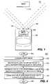
- FIG. 1depicts one embodiment of a schematic view of a vehicle utilizing the present invention
- FIG. 2depicts a block diagram of a vehicular vision system in accordance with one embodiment of the present invention
- FIG. 3depicts a block diagram of functional modules of the vision system of FIG. 2 in accordance with one embodiment of the present invention
- FIG. 4illustrates a flow diagram in accordance with a method of the present invention
- FIG. 5illustrates an example of information derived from a depth image in accordance with one embodiment of the present invention.
- FIG. 6illustrates an example of information derived from a depth image in accordance with one embodiment of the present invention.
- the present inventiondiscloses in one embodiment a method and apparatus for classifying an object in a region of interest based on one or more features of the object. Detection and classification of pedestrians, vehicles, and other objects are important, e.g., for automotive safety devices, since these devices may deploy in a particular fashion only if a target of the particular type (i.e., pedestrian or car) is about to be impacted. In particular, measures employed to mitigate the injury to a pedestrian may be very different from those employed to mitigate damage and injury from a vehicle-to-vehicle collision.
- FIG. 1depicts a schematic diagram of a host, e.g., vehicle 100 having a target differentiation system 102 that differentiates a pedestrian (or pedestrians) 110 within a scene 104 that is proximate the vehicle 100 .
- target differentiation system 102is operable to detect pedestrians, automobiles, or other objects. While in the illustrated embodiment scene 104 is in front of vehicle 100 , other object detection systems may image scenes that are behind or to the side of vehicle 100 .
- target differentiation system 102need not be related to a vehicle, but can be used with any type of platform, such as a boat, a plane, an elevator, or even stationary streets, docks, or floors.
- Target differentiation system 102comprises a sensor array 106 that is coupled to an image processor 108 . The sensors within the sensor array 106 have a field of view that includes one or more targets.
- the field of view in a practical object detection system 102may be ⁇ 12 meters horizontally in front of the vehicle 100 (e.g., approximately 3 traffic lanes), with a ⁇ 3 meter vertical area, and have a view depth of approximately 5–40 meters. (Other fields of view and ranges are possible, depending on camera optics and the particular application.) Therefore, it should be understood that the present invention can be used in a pedestrian detection system or as part of a collision avoidance system.
- FIG. 2depicts a block diagram of hardware used to implement the target differentiation system 102 .
- the sensor array 106comprises, for example, a pair of cameras 200 and 202 .
- an optional secondary sensor 204can be included.
- the secondary sensor 204may be radar, a light detection and ranging (LIDAR) sensor, an infrared range finder, a sound navigation and ranging (SONAR) senor, and the like.
- the cameras 200 and 202generally operate in the visible wavelengths, but may be augmented with infrared sensors, or the cameras may themselves operate in the infrared range.
- the camerashave a known, fixed relation to one another such that they can produce a stereo image of the scene 104 . Therefore, the cameras 200 and 202 will sometimes be referred to herein as stereo cameras.
- the image processor 108comprises an image preprocessor 206 , a central processing unit (CPU) 210 , support circuits 208 , and memory 212 .
- the image preprocessor 206generally comprises circuitry for capturing, digitizing and processing the imagery from the sensor array 106 .
- the image preprocessormay be a single chip video processor such as the processor manufactured under the model Acadia ITM by Pyramid Vision Technologies of Princeton, N.J.
- the processed images from the image preprocessor 206are coupled to the CPU 210 .
- the CPU 210may comprise any one of a number of presently available high speed microcontrollers or microprocessors.
- CPU 210is supported by support circuits 208 that are generally well known in the art. These circuits include cache, power supplies, clock circuits, input-output circuitry, and the like.
- Memory 212is also coupled to CPU 210 .
- Memory 212stores certain software routines that are retrieved from a storage medium, e.g., an optical disk, and the like, and that are executed by CPU 210 to facilitate operation of the present invention.
- Memory 212also stores certain databases 214 of information that are used by the present invention, and image processing software 216 that is used to process the imagery from the sensor array 106 .
- the present inventionis described in the context of a series of method steps, the method may be performed in hardware, software, or some combination of hardware and software (e.g., an ASIC). Additionally, the methods as disclosed can
- FIG. 3is a functional block diagram of modules that are used to implement the present invention.
- the stereo cameras 200 and 202provide stereo imagery to a stereo image preprocessor 300 .
- the stereo image preprocessoris coupled to a depth map generator 302 which is coupled to a target processor 304 .
- Depth map generator 302may be utilized to define a region of interest (ROI), i.e., an area of the image that potentially contains a target 110 . In some applications the depth map generator 302 is not used. In applications where depth map generator 302 is not used, ROIs would be determined using image-based methods. The following will describe the functional block diagrams under the assumption that a depth map generator 302 is used.
- ROIregion of interest
- the target processor 304receives information from a target template database 306 and from the optional secondary sensor 204 .
- the stereo image preprocessor 300calibrates the stereo cameras, captures and digitizes imagery, warps the images into alignment, performs pyramid wavelet decomposition, and performs stereo matching, which is generally well known in the art, to create disparity images at different resolutions.
- disparity images having different resolutionsare beneficial when detecting objects.
- Calibrationprovides for a reference point and direction from which all distances and angles are determined.
- Each of the disparity imagescontains the point-wise motion from the left image to the right image and each corresponds to a different image resolution. The greater the computed disparity of an imaged object, the closer the object is to the sensor array.
- the depth map generator 302processes the multi-resolution disparity images into a two-dimensional depth image.
- the depth image(also referred to as a depth map) contains image points or pixels in a two dimensional array, where each point represents the depth (z coordinate in the camera coordinate system) of a point within the scene.
- the depth imageis then processed by the target processor 304 wherein templates (models) of typical objects encountered by the vision system are compared to the information within the depth image.
- the template database 306comprises templates of objects (e.g., automobiles, pedestrians) located at various locations and poses with respect to the sensor array.
- the secondary sensor 204may provide additional information regarding the position of the object relative to the vehicle, velocity of the object, size or angular width of the object, etc., such that the target template search process can be limited to templates of objects at about the known position relative to the vehicle. If the secondary sensor is a radar sensor, the sensor can, for example, provide an estimate of both object location and velocity.
- the target processor 304produces a target list that is then used to identify target size and classification estimates that enable target tracking and the identification of each target's position, classification and velocity within the scene. That information may then be used to avoid collisions with each target or perform pre-crash alterations to the vehicle to mitigate or eliminate damage (e.g., lower or raise the vehicle, deploy air bags, and the like).
- FIG. 4depicts a flow diagram of a method 400 for classifying an object in an image.
- the method 400begins at step 405 and proceeds to step 410 .
- a depth imageis provided.
- Depth imagesmay be provided by depth map generator 302 .
- depth map generator 302processes multi-resolution disparity images into a two-dimensional depth image.
- the depth imagemay be represented in a three-dimensional “real-world” sense with three two-dimensional matrices representing the X, Y, and Z coordinates of each pixel in the left camera image, where X represents a three dimensional lateral coordinate, Y represents a three-dimensional vertical coordinate, and Z represents a three dimensional depth coordinate.
- the depth imagemay also be represented as a two-dimensional depth image (x, y), where x represents depth image column and y represents depth image row.
- the former representationcan be obtained given the latter representation and the associated camera calibration information.
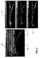
- FIG. 5illustrates an example of parameters derived using the above Cartesian coordinates and depth image coordinates.
- An original stereoscopic imageis shown in element 505 where a target 506 is misclassified as two pedestrians by a different classification algorithm.
- Parameter Zdyis a measure of how three-dimensional depth coordinate (Z) changes across a 1 ⁇ 3 meter vertical interval (projected into image rows (y)) and is shown in element 510 , in which luminance values are assigned in proportion with the magnitude of the Zdy output.
- Parameter Ydyis a measure of how three-dimensional vertical coordinate (Y) changes across a 1 ⁇ 3 meter vertical interval (projected into image rows (y)).
- Parameter Xdxis a measure of how three-dimensional lateral coordinate (X) changes across a 1 ⁇ 3 meter horizontal interval (projected into image columns (x)) and is shown in element 515 .
- Parameter Zdxis a measure of how three-dimensional depth coordinate (Z) changes across a 1 ⁇ 3 meter horizontal interval (projected into image columns (x)) and is shown in element 520 .
- the measurement interval of 1 ⁇ 3 meteris appropriate for the application of detecting and discriminating targets such as pedestrians and vehicles, but can vary depending on the application.
- step 415at least one area of the depth image that is unsatisfactory for object identification is identified.
- parameter Zdyis determined for the depth image.
- Zdyis a measure of how three-dimensional depth coordinate (Z) changes across a 1 ⁇ 3 meter vertical interval (projected into image rows (y)). If the row being measured is at ground level, a high Zdy value is expected since the difference between ground and the horizon represents a significant change in three-dimensional depth (Z). Areas of the depth image having a high Zdy value are eliminated from consideration.
- a thresholdis selected to determine high Zdy values based on knowledge of common road gradations and noise in the depth image. High Zdy values should correspond to flat regions in the scene.
- a threshold of 0.5is chosen, and all pixels whose local Zdy value is greater than 0.5 are labeled as road pixels and thereby eliminated from consideration.
- Zdymay be used in combination with Ydy, to estimate an actual road pitch or ground plane angle, where Ydy is a measure of how three-dimensional vertical coordinate (Y) changes across a 1 ⁇ 3 meter vertical interval (projected into image rows (y)).
- a thresholdis selected to determine low pitch values based on knowledge of common road gradations and noise in the depth image. Low pitch values should correspond to flat regions in the scene. In one embodiement a threshold of 0.3491 radians is chosen (20 degrees), and all pixels whose local pitch is less than 0.3491 are labeled as road pixels and thereby eliminated from consideration. High pitch values indicate the presence of an upright object on the road.
- a plurality of two-dimensional in-plane rotations (two-dimensional projections of surface normals) in the depth imageis determined without considering the unsatisfactory area(s).
- Parameter Xdxis determined for the depth image.
- Xdxis a measure of how three-dimensional lateral coordinate (X) changes across a 1 ⁇ 3 meter horizontal interval (projected into image columns (x)).
- Parameter xmay be incremented with respect to parameter X. For example, where a target 506 is in front of a host e.g., host 100 in an adjacent lane, an X value corresponding to the side of that target would change very little, if at all, when x is varied.
- Parameter Zdxis also determined for the depth image.
- Zdxis a measure of how three-dimensional depth coordinate (Z) changes across a 1 ⁇ 3 meter horizontal interval (projected into image columns (x)).
- Zthree-dimensional depth coordinate
- x1 ⁇ 3 meter horizontal interval
- a plurality of theta (yaw) valuese.g., two-dimensional projections of surface normals in the X-Z plane is determined in areas of the depth image deemed satisfactory for object identification, e.g., areas having a low Zdy or a high Psi.
- Subsets of the plurality of two-dimensional projections of surface normals that are close in proximity and exhibit similar theta valuesare regarded as surfaces of one or more objects, e.g., a vehicle, a person, a wall, and so forth.
- one or more objectsare classified based on the plurality of two-dimensional projections of surface normals.
- one or more objectsis classified as a side of a vehicle when a subset of the plurality of two-dimensional projections of surface normals is within 20 degrees of being orthogonal to the optical axis of a host, e.g., host 100 .
- an objectis classified using object width when over fifty percent of a subset of said plurality of two-dimensional projections of surface normals are within 20 degrees of being orthogonal to the camera's optical axis.
- FIG. 6illustrates an example of parameters derived using the above Cartesian coordinates and depth image coordinates.
- An original stereoscopic imageis shown in element 605 where a target 606 is misclassified as two pedestrians by a different classification algorithm.
- Element 610illustrates that the system correctly identifies target 611 as a car using the A tan 2 function.
- the A tan 2 functionreturns an angle of ⁇ 75° with respect to the camera's optical axis, which is very close to the expected orientation of the right side of a vehicle detected in front and off to the left of a host.
- Element 615illustrates a depth image displaying computed theta values.
Landscapes
- Engineering & Computer Science (AREA)
- Physics & Mathematics (AREA)
- General Physics & Mathematics (AREA)
- Multimedia (AREA)
- Theoretical Computer Science (AREA)
- Software Systems (AREA)
- Traffic Control Systems (AREA)
- Image Analysis (AREA)
- Image Processing (AREA)
Abstract
Description
ψ=Atan 2(Ydy, Zdy)
where A tan2 is a trigonometric function with two inputs, Ydy and Zdy. Areas of the depth image having a low pitch value (e.g., flat areas) are eliminated from consideration. A threshold is selected to determine low pitch values based on knowledge of common road gradations and noise in the depth image. Low pitch values should correspond to flat regions in the scene. In one embodiement a threshold of 0.3491 radians is chosen (20 degrees), and all pixels whose local pitch is less than 0.3491 are labeled as road pixels and thereby eliminated from consideration. High pitch values indicate the presence of an upright object on the road.
θ=Atan 2(Xdx, Zdx)
where A tan2 is a trigonometric function with two inputs, Xdx and Zdx.
Claims (20)
Priority Applications (1)
| Application Number | Priority Date | Filing Date | Title |
|---|---|---|---|
| US11/070,566US7103213B2 (en) | 2004-03-02 | 2005-03-02 | Method and apparatus for classifying an object |
Applications Claiming Priority (2)
| Application Number | Priority Date | Filing Date | Title |
|---|---|---|---|
| US54920304P | 2004-03-02 | 2004-03-02 | |
| US11/070,566US7103213B2 (en) | 2004-03-02 | 2005-03-02 | Method and apparatus for classifying an object |
Publications (2)
| Publication Number | Publication Date |
|---|---|
| US20050270286A1 US20050270286A1 (en) | 2005-12-08 |
| US7103213B2true US7103213B2 (en) | 2006-09-05 |
Family
ID=34919451
Family Applications (1)
| Application Number | Title | Priority Date | Filing Date |
|---|---|---|---|
| US11/070,566Expired - LifetimeUS7103213B2 (en) | 2004-03-02 | 2005-03-02 | Method and apparatus for classifying an object |
Country Status (2)
| Country | Link |
|---|---|
| US (1) | US7103213B2 (en) |
| WO (1) | WO2005086078A1 (en) |
Cited By (10)
| Publication number | Priority date | Publication date | Assignee | Title |
|---|---|---|---|---|
| US20060210117A1 (en)* | 2003-06-13 | 2006-09-21 | Peng Chang | Method and apparatus for ground detection and removal in vision systems |
| US20070237398A1 (en)* | 2004-08-27 | 2007-10-11 | Peng Chang | Method and apparatus for classifying an object |
| US7995055B1 (en) | 2007-05-25 | 2011-08-09 | Google Inc. | Classifying objects in a scene |
| US8274552B2 (en) | 2010-12-27 | 2012-09-25 | 3Dmedia Corporation | Primary and auxiliary image capture devices for image processing and related methods |
| US8436893B2 (en) | 2009-07-31 | 2013-05-07 | 3Dmedia Corporation | Methods, systems, and computer-readable storage media for selecting image capture positions to generate three-dimensional (3D) images |
| US8508580B2 (en) | 2009-07-31 | 2013-08-13 | 3Dmedia Corporation | Methods, systems, and computer-readable storage media for creating three-dimensional (3D) images of a scene |
| US9185388B2 (en) | 2010-11-03 | 2015-11-10 | 3Dmedia Corporation | Methods, systems, and computer program products for creating three-dimensional video sequences |
| US9344701B2 (en) | 2010-07-23 | 2016-05-17 | 3Dmedia Corporation | Methods, systems, and computer-readable storage media for identifying a rough depth map in a scene and for determining a stereo-base distance for three-dimensional (3D) content creation |
| US9380292B2 (en) | 2009-07-31 | 2016-06-28 | 3Dmedia Corporation | Methods, systems, and computer-readable storage media for generating three-dimensional (3D) images of a scene |
| US10200671B2 (en) | 2010-12-27 | 2019-02-05 | 3Dmedia Corporation | Primary and auxiliary image capture devices for image processing and related methods |
Families Citing this family (15)
| Publication number | Priority date | Publication date | Assignee | Title |
|---|---|---|---|---|
| DE102005024716B4 (en)* | 2005-05-30 | 2023-09-21 | Robert Bosch Gmbh | Method and device for recognizing and classifying objects |
| DE102008024308B4 (en)* | 2008-05-20 | 2010-12-09 | Eads Deutschland Gmbh | Method for detecting non-cooperative aviation on board an aircraft |
| JP5425897B2 (en)* | 2008-05-28 | 2014-02-26 | トムソン ライセンシング | Image depth extraction system and method with forward and backward depth prediction |
| EP2356818B1 (en)* | 2008-12-01 | 2016-04-13 | Imax Corporation | Methods and systems for presenting three-dimensional motion pictures with content adaptive information |
| EP2254091B1 (en)* | 2009-05-19 | 2020-03-25 | Veoneer Sweden AB | Vision system and method for a motor vehicle |
| WO2011114815A1 (en)* | 2010-03-17 | 2011-09-22 | 本田技研工業株式会社 | Vehicle surroundings monitoring device |
| US8395659B2 (en)* | 2010-08-26 | 2013-03-12 | Honda Motor Co., Ltd. | Moving obstacle detection using images |
| US9256961B2 (en)* | 2012-06-28 | 2016-02-09 | Here Global B.V. | Alternate viewpoint image enhancement |
| US9256983B2 (en) | 2012-06-28 | 2016-02-09 | Here Global B.V. | On demand image overlay |
| US9772281B2 (en) | 2014-10-25 | 2017-09-26 | Isle Management Co. | Air quality analyzing apparatus |
| US20170032676A1 (en)* | 2015-07-30 | 2017-02-02 | Illinois Institute Of Technology | System for detecting pedestrians by fusing color and depth information |
| US9887497B1 (en)* | 2016-06-10 | 2018-02-06 | Amazon Technologies, Inc. | Device connector with reduced electromagnetic noise |
| US10884409B2 (en)* | 2017-05-01 | 2021-01-05 | Mentor Graphics (Deutschland) Gmbh | Training of machine learning sensor data classification system |
| US10657666B2 (en)* | 2017-12-22 | 2020-05-19 | Symbol Technologies, Llc | Systems and methods for determining commercial trailer fullness |
| US11461915B2 (en)* | 2020-01-06 | 2022-10-04 | Qualcomm Incorporated | Object size estimation using camera map and/or radar information |
Citations (7)
| Publication number | Priority date | Publication date | Assignee | Title |
|---|---|---|---|---|
| US5283837A (en)* | 1991-08-27 | 1994-02-01 | Picker International, Inc. | Accurate estimation of surface normals in 3-D data sets |
| US5793375A (en)* | 1994-11-09 | 1998-08-11 | Kabushiki Kaisha Toshiba | Image processing apparatus for forming a surface display image |
| US5793900A (en)* | 1995-12-29 | 1998-08-11 | Stanford University | Generating categorical depth maps using passive defocus sensing |
| US5809161A (en)* | 1992-03-20 | 1998-09-15 | Commonwealth Scientific And Industrial Research Organisation | Vehicle monitoring system |
| US6396535B1 (en)* | 1999-02-16 | 2002-05-28 | Mitsubishi Electric Research Laboratories, Inc. | Situation awareness system |
| US20040075654A1 (en)* | 2002-10-16 | 2004-04-22 | Silicon Integrated Systems Corp. | 3-D digital image processor and method for visibility processing for use in the same |
| US6956469B2 (en)* | 2003-06-13 | 2005-10-18 | Sarnoff Corporation | Method and apparatus for pedestrian detection |
Family Cites Families (2)
| Publication number | Priority date | Publication date | Assignee | Title |
|---|---|---|---|---|
| US5542032A (en)* | 1993-10-04 | 1996-07-30 | Loral Federal Systems Company | Fast display of images of three-dimensional surfaces without aliasing |
| US6678394B1 (en)* | 1999-11-30 | 2004-01-13 | Cognex Technology And Investment Corporation | Obstacle detection system |
- 2005
- 2005-03-02WOPCT/US2005/006758patent/WO2005086078A1/enactiveApplication Filing
- 2005-03-02USUS11/070,566patent/US7103213B2/ennot_activeExpired - Lifetime
Patent Citations (7)
| Publication number | Priority date | Publication date | Assignee | Title |
|---|---|---|---|---|
| US5283837A (en)* | 1991-08-27 | 1994-02-01 | Picker International, Inc. | Accurate estimation of surface normals in 3-D data sets |
| US5809161A (en)* | 1992-03-20 | 1998-09-15 | Commonwealth Scientific And Industrial Research Organisation | Vehicle monitoring system |
| US5793375A (en)* | 1994-11-09 | 1998-08-11 | Kabushiki Kaisha Toshiba | Image processing apparatus for forming a surface display image |
| US5793900A (en)* | 1995-12-29 | 1998-08-11 | Stanford University | Generating categorical depth maps using passive defocus sensing |
| US6396535B1 (en)* | 1999-02-16 | 2002-05-28 | Mitsubishi Electric Research Laboratories, Inc. | Situation awareness system |
| US20040075654A1 (en)* | 2002-10-16 | 2004-04-22 | Silicon Integrated Systems Corp. | 3-D digital image processor and method for visibility processing for use in the same |
| US6956469B2 (en)* | 2003-06-13 | 2005-10-18 | Sarnoff Corporation | Method and apparatus for pedestrian detection |
Non-Patent Citations (2)
| Title |
|---|
| 3D Scene Reconstruction and Object Recognition for use with Autonomously Guided Vehicles, IEEE 0-7803-3026-9/95, pp. 1219-1224.* |
| Chang et al., Stero-Based Object Detection, Classification and Quantative Evaluation with Automotive Applications, IEEE 1063-6919/05, pp. 1-6.* |
Cited By (18)
| Publication number | Priority date | Publication date | Assignee | Title |
|---|---|---|---|---|
| US20060210117A1 (en)* | 2003-06-13 | 2006-09-21 | Peng Chang | Method and apparatus for ground detection and removal in vision systems |
| US7957562B2 (en)* | 2003-06-13 | 2011-06-07 | Sri International | Method and apparatus for ground detection and removal in vision systems |
| US20070237398A1 (en)* | 2004-08-27 | 2007-10-11 | Peng Chang | Method and apparatus for classifying an object |
| US7466860B2 (en)* | 2004-08-27 | 2008-12-16 | Sarnoff Corporation | Method and apparatus for classifying an object |
| US7995055B1 (en) | 2007-05-25 | 2011-08-09 | Google Inc. | Classifying objects in a scene |
| US8508580B2 (en) | 2009-07-31 | 2013-08-13 | 3Dmedia Corporation | Methods, systems, and computer-readable storage media for creating three-dimensional (3D) images of a scene |
| US8436893B2 (en) | 2009-07-31 | 2013-05-07 | 3Dmedia Corporation | Methods, systems, and computer-readable storage media for selecting image capture positions to generate three-dimensional (3D) images |
| US8810635B2 (en) | 2009-07-31 | 2014-08-19 | 3Dmedia Corporation | Methods, systems, and computer-readable storage media for selecting image capture positions to generate three-dimensional images |
| US9380292B2 (en) | 2009-07-31 | 2016-06-28 | 3Dmedia Corporation | Methods, systems, and computer-readable storage media for generating three-dimensional (3D) images of a scene |
| US11044458B2 (en) | 2009-07-31 | 2021-06-22 | 3Dmedia Corporation | Methods, systems, and computer-readable storage media for generating three-dimensional (3D) images of a scene |
| US12034906B2 (en) | 2009-07-31 | 2024-07-09 | 3Dmedia Corporation | Methods, systems, and computer-readable storage media for generating three-dimensional (3D) images of a scene |
| US9344701B2 (en) | 2010-07-23 | 2016-05-17 | 3Dmedia Corporation | Methods, systems, and computer-readable storage media for identifying a rough depth map in a scene and for determining a stereo-base distance for three-dimensional (3D) content creation |
| US9185388B2 (en) | 2010-11-03 | 2015-11-10 | 3Dmedia Corporation | Methods, systems, and computer program products for creating three-dimensional video sequences |
| US8441520B2 (en) | 2010-12-27 | 2013-05-14 | 3Dmedia Corporation | Primary and auxiliary image capture devcies for image processing and related methods |
| US8274552B2 (en) | 2010-12-27 | 2012-09-25 | 3Dmedia Corporation | Primary and auxiliary image capture devices for image processing and related methods |
| US10200671B2 (en) | 2010-12-27 | 2019-02-05 | 3Dmedia Corporation | Primary and auxiliary image capture devices for image processing and related methods |
| US10911737B2 (en) | 2010-12-27 | 2021-02-02 | 3Dmedia Corporation | Primary and auxiliary image capture devices for image processing and related methods |
| US11388385B2 (en) | 2010-12-27 | 2022-07-12 | 3Dmedia Corporation | Primary and auxiliary image capture devices for image processing and related methods |
Also Published As
| Publication number | Publication date |
|---|---|
| US20050270286A1 (en) | 2005-12-08 |
| WO2005086078A1 (en) | 2005-09-15 |
Similar Documents
| Publication | Publication Date | Title |
|---|---|---|
| US7103213B2 (en) | Method and apparatus for classifying an object | |
| US20050232463A1 (en) | Method and apparatus for detecting a presence prior to collision | |
| US6956469B2 (en) | Method and apparatus for pedestrian detection | |
| CN107272021B (en) | Object detection using radar and visually defined image detection areas | |
| US7068815B2 (en) | Method and apparatus for ground detection and removal in vision systems | |
| US7672514B2 (en) | Method and apparatus for differentiating pedestrians, vehicles, and other objects | |
| US7403659B2 (en) | Method and apparatus for differentiating pedestrians, vehicles, and other objects | |
| US7263209B2 (en) | Vehicular vision system | |
| US7660436B2 (en) | Stereo-vision based imminent collision detection | |
| US7697786B2 (en) | Method and apparatus for detecting edges of an object | |
| JP6151150B2 (en) | Object detection device and vehicle using the same | |
| JP3822515B2 (en) | Obstacle detection device and method | |
| US11087150B2 (en) | Detection and validation of objects from sequential images of a camera by using homographies | |
| US7466860B2 (en) | Method and apparatus for classifying an object | |
| Ma et al. | A real time object detection approach applied to reliable pedestrian detection | |
| Nedevschi et al. | Stereo image processing for adas and pre-crash systems |
Legal Events
| Date | Code | Title | Description |
|---|---|---|---|
| AS | Assignment | Owner name:SARNOFF CORPORATION, NEW JERSEY Free format text:ASSIGNMENT OF ASSIGNORS INTEREST;ASSIGNORS:HIRVONEN, DAVID;CAMUS, THEODORE ARMAND;REEL/FRAME:016601/0166 Effective date:20050506 | |
| STCF | Information on status: patent grant | Free format text:PATENTED CASE | |
| FPAY | Fee payment | Year of fee payment:4 | |
| AS | Assignment | Owner name:SRI INTERNATIONAL, CALIFORNIA Free format text:MERGER;ASSIGNOR:SARNOFF CORPORATION;REEL/FRAME:031043/0610 Effective date:20110204 | |
| FPAY | Fee payment | Year of fee payment:8 | |
| MAFP | Maintenance fee payment | Free format text:PAYMENT OF MAINTENANCE FEE, 12TH YEAR, LARGE ENTITY (ORIGINAL EVENT CODE: M1553) Year of fee payment:12 | |
| AS | Assignment | Owner name:IP3 2019, SERIES 400 OF ALLIED SECURITY TRUST I, C Free format text:ASSIGNMENT OF ASSIGNORS INTEREST;ASSIGNOR:SRI INTERNATIONAL;REEL/FRAME:051355/0223 Effective date:20191121 | |
| AS | Assignment | Owner name:ZAMA INNOVATIONS LLC, DELAWARE Free format text:ASSIGNMENT OF ASSIGNORS INTEREST;ASSIGNOR:IP3 2019, SERIES 400 OF ALLIED SECURITY TRUST I;REEL/FRAME:057407/0395 Effective date:20210825 |