US7103032B2 - Telephone controller for VoIP - Google Patents
Telephone controller for VoIPDownload PDFInfo
- Publication number
- US7103032B2 US7103032B2US09/738,981US73898100AUS7103032B2US 7103032 B2US7103032 B2US 7103032B2US 73898100 AUS73898100 AUS 73898100AUS 7103032 B2US7103032 B2US 7103032B2
- Authority
- US
- United States
- Prior art keywords
- telephone
- address
- internet
- private
- telephones
- Prior art date
- Legal status (The legal status is an assumption and is not a legal conclusion. Google has not performed a legal analysis and makes no representation as to the accuracy of the status listed.)
- Expired - Lifetime, expires
Links
- 238000004891communicationMethods0.000claimsabstractdescription18
- 230000004044responseEffects0.000claimsdescription12
- 238000012546transferMethods0.000claimsdescription7
- 239000000284extractSubstances0.000claimsdescription3
- 238000010586diagramMethods0.000description13
- 238000000034methodMethods0.000description13
- 230000006870functionEffects0.000description5
- 238000006243chemical reactionMethods0.000description3
- 230000005540biological transmissionEffects0.000description1
- 238000005516engineering processMethods0.000description1
- 238000012986modificationMethods0.000description1
- 230000004048modificationEffects0.000description1
- 238000012545processingMethods0.000description1
Images


Classifications
- H—ELECTRICITY
- H04—ELECTRIC COMMUNICATION TECHNIQUE
- H04M—TELEPHONIC COMMUNICATION
- H04M7/00—Arrangements for interconnection between switching centres
- H04M7/006—Networks other than PSTN/ISDN providing telephone service, e.g. Voice over Internet Protocol (VoIP), including next generation networks with a packet-switched transport layer
- H—ELECTRICITY
- H04—ELECTRIC COMMUNICATION TECHNIQUE
- H04L—TRANSMISSION OF DIGITAL INFORMATION, e.g. TELEGRAPHIC COMMUNICATION
- H04L61/00—Network arrangements, protocols or services for addressing or naming
- H04L61/45—Network directories; Name-to-address mapping
- H04L61/4557—Directories for hybrid networks, e.g. including telephone numbers
- H—ELECTRICITY
- H04—ELECTRIC COMMUNICATION TECHNIQUE
- H04L—TRANSMISSION OF DIGITAL INFORMATION, e.g. TELEGRAPHIC COMMUNICATION
- H04L61/00—Network arrangements, protocols or services for addressing or naming
- H04L61/50—Address allocation
- H04L61/5038—Address allocation for local use, e.g. in LAN or USB networks, or in a controller area network [CAN]
- H—ELECTRICITY
- H04—ELECTRIC COMMUNICATION TECHNIQUE
- H04L—TRANSMISSION OF DIGITAL INFORMATION, e.g. TELEGRAPHIC COMMUNICATION
- H04L65/00—Network arrangements, protocols or services for supporting real-time applications in data packet communication
- H04L65/10—Architectures or entities
- H04L65/1046—Call controllers; Call servers
- H—ELECTRICITY
- H04—ELECTRIC COMMUNICATION TECHNIQUE
- H04L—TRANSMISSION OF DIGITAL INFORMATION, e.g. TELEGRAPHIC COMMUNICATION
- H04L51/00—User-to-user messaging in packet-switching networks, transmitted according to store-and-forward or real-time protocols, e.g. e-mail
Definitions
- the present inventionrelates to a telephone controller for VoIP.
- VoIPVoice over IP
- TCP/IPTransmission Control Protocol/IP
- a telephonealso makes a call based on TCP/IP. That is, a calling telephone sends voice information, split into packets based on TCP/IP, to a receiving telephone.
- communication via VoIPrequires the management of global IP addresses allocated to the telephones. This is because a global IP address must be globally unique.
- a rapid increase in the number of Internet terminalsproduces some problems; for example, the available global IP addresses become insufficient, and an increased number of globally-registered IP addresses makes the management of global IP addresses more complex. For example, when a plurality of telephones are connected to the Internet via a LAN, it is difficult to allocate a globally-unique IP address to each telephone in the LAN.
- a private IP addressis assigned to each telephone in a LAN and the address is converted between the private IP address and the global IP address.
- This methodrequires a router with the network address translator (NAT) function to be installed between the LAN and the Internet to allow the NAT to translate the private IP address of each telephone to a global IP address.
- This routerprevents external units from directly accessing the terminals in the LAN to ensure security.
- This mechanismis called a firewall. Therefore, the NAT function, once installed, allows a telephone in the LAN to make a call to an external telephone over the Internet but prevents an external telephone connected to the Internet from directly making a call to a telephone in the LAN.
- a telephone controllercontrols a plurality of telephones connected to the Internet via a LAN, the telephone controller comprising:
- IP address allocating circuitwhich allocates a private IP address to each of the plurality of telephones
- a memoryin which a table indicating a correspondence between IDs of the plurality of telephones and the private IP addresses is stored;
- control circuitwhich controls communication between the plurality of telephones and the Internet using the private IP addresses
- the IDincludes a domain name of the telephone controller and identification information.
- FIG. 1is a block diagram showing a first embodiment of a telephone controller according to the present invention.
- FIG. 2is a diagram showing the contents of a table stored in the memory of the telephone controller shown in FIG. 1 .
- FIG. 3is a diagram showing a registration request IP packet created by the telephone in FIG. 1 .
- FIG. 4is a diagram showing the contents of a history information table stored in the memory of the telephone controller shown in FIG. 1 .
- FIG. 5is a block diagram showing an IP packet created by the telephone shown in FIG. 1 .
- FIG. 6is a diagram showing the configuration of the telephone shown in FIG. 1 .
- FIG. 7is a block diagram showing the embodiment in which external telephones and a name server are connected to the Internet shown in FIG. 1 .
- FIG. 8is a sequence diagram showing a communication operation between an external telephone and a telephone in a LAN.
- FIG. 9is a block diagram showing a second embodiment of the telephone controller according to the present invention.
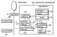
- FIG. 1is a block diagram showing an embodiment of the present invention.
- a telephone controller 100controls telephones 200 and 201 via a LAN interface circuit 120 .
- the telephone controller 100comprises a control circuit 110 executing TCP/IP, an IP address allocating circuit 122 allocating private IP addresses to the telephones 200 and 201 in response to an instruction from the control circuit 110 , a header analyzing circuit 121 analyzing the header of an IP packet received from LAN 1 , and a memory 130 storing therein a table 131 representing the correspondence among an ID, a private IP address, an extension telephone number, and a user name.
- the IDis represented in the form (user name) (extension telephone number)@(domain name), for example, kobayashi100@soho-ip.abc.co.jp.
- the user nameis the name of a user of the telephone 200 or 201
- the domain name “soho-ip.abc.co.jp”is the domain name of the telephone controller 100 on the Internet.
- the user name and the extension telephone numberare used to identify a telephone to be controlled by the telephone controller 100 .
- the ID, the extension telephone number, and the user nameare entered by the user using an input circuit 123 .
- LAN 1is a LAN built around a known technology such as 10BASE-T or 100BASE-TX. Although two telephones are used in FIG. 1 , three or more may also be used.
- the private IP address of the telephone 200 or 201is created according to the procedure described below.
- the LAN interface circuit 120informs the control circuit 110 that the telephone 200 may communicate with the telephone controller 100 .
- the control circuit 110outputs an IP address allocation instruction to the IP address allocating circuit 122 .
- the IP address allocating circuit 122creates a private IP address (“XXX.XXX.XXX.001” (X is any number)) for the telephone 200 made available for communication and sends the created address to the control circuit 110 .
- the private IP addressis created automatically by the IP address allocating circuit 122 each time the telephone moves from the inactive state to the active state.
- the created private IP address of the telephone 200is sent to the telephone 200 .
- the control circuit 110associates the private IP address allocated to the telephone 200 with the ID, extension telephone number, and user name and stores the created entry in the table 131 .
- the data structure of the table 131is shown in FIG. 2 .
- the private IP address of the telephone 201is also created in the same manner according to the procedure described above.
- An ID, extension telephone number, and user name stored in the table 131may be updated via the input circuit 123 of the telephone controller 100 . They may also be updated by an instruction from the telephone 200 or 201 . The following describes the method.
- the telephone 200sends an ID registration request message to the telephone controller 100 .
- the ID registration request messageis sent in the format of the packet shown in FIG. 3 .
- This packetcomprises an IP address 310 , a header 311 , and an ID 312 .
- the IP address 310is composed of the private IP address of the telephone 200 which is the source and the IP address of the telephone controller 100 which is the destination.
- the private IP addressis the IP address notified by the telephone controller 100 .
- the header 311contains control information such as the ID registration command and the data length.
- the ID 312contains the ID of the telephone 200 .
- the user of the telephone 200stores, in advance, his or her own ID into the memory of the telephone 200 .
- the telephone 200generates an ID registration request message, for example, when the user enters a request from the operation panel of the telephone, when the telephone controller 100 notifies an IP address, each time a predetermined time elapses, when the power is turned on, or when an ID is set.
- the LAN interface circuit 120receives a packet, shown in FIG. 3 , from the telephone 200 .
- the LAN interface circuit 120sends the received packet to the control circuit 110 via the header analyzing circuit 121 .
- the control circuit 110obtains the source IP address (private IP address of the telephone 200 ) and the ID from the packet.
- the control circuit 110obtains the user name and the extension telephone number from the obtained ID.
- the control circuit 110accesses the table in the memory 130 to update the ID, extension telephone number, and user name corresponding to the obtained private IP address.
- To update either the user name or the extension telephone number stored in the IDonly a user name 300 or an extension telephone number 301 may be stored in the ID 312 .
- FIG. 7shows a configuration in which a telephone 510 with the IP communication function is connected to the Internet 2 .
- the telephone 510is connected to the Internet 2 , either directly or via a LAN. Or, as in a dial-up connection configuration, the telephone 510 may dial up the Internet service provider to temporarily connect to the Internet.
- a name server 501is an IP address and domain name management server such as Domain Name Server System (DNS) or CHAT. This name server is connected to the Internet 2 . Except the telephone 510 and the name server 501 , the configuration shown in FIG. 7 is similar to that shown in FIG. 1 .
- DNSDomain Name Server System
- FIG. 8is a diagram showing the operation sequence in which the telephone 510 connected to the Internet makes a call to the telephone 200 in the LAN.
- the telephone 510extracts the domain name from the ID and sends an address request to the name server 501 .
- This domain nameis “soho-ip.abc.co.jp” which is the domain name of the telephone controller 100 controlling the telephone 200 .
- the name server 501sends the global IP address, corresponding to the domain name, to the telephone 510 .
- the telephone 510creates an IP packet with the received global IP address as the destination IP address and sends the packet to a router 3 .
- the IP packet that is sentis shown in FIG. 5 .
- the global IP address of the telephone controller 100is stored in an IP address 410 shown in FIG. 5 , while the ID “kobayashi100@soho-ip.abc.co.jp” of the telephone 200 is stored in an ID 412 .
- the router 3sends the IP packet received from the telephone 510 to the telephone controller 100 .
- This IP packetis sent to the header analyzing circuit 121 via the LAN interface circuit 120 .
- the header analyzing circuit 121analyzes the header of the IP packet and then sends the ID stored in the ID 412 to the control circuit 110 .
- the control circuit 110searches the table 131 with the user name or the extension telephone number contained in the ID to obtain the private IP address of the telephone 200 . Then, the control circuit creates a reception notification packet with the private IP address of the telephone 200 as the destination IP address and sends the created packet to the telephone 200 via the LAN interface circuit 120 . This causes a control circuit 220 (shown in FIG. 6 ) in the telephone 200 to ring the bell. When the user of the telephone 200 lifts the telephone receiver, the telephone 200 creates a response packet and sends the created response packet to the telephone controller 100 . The telephone controller 100 sends the response packet back to the telephone 510 via the Internet 2 .
- IP packets containing voiceis transferred between the telephone 510 and the telephone 200 .
- the telephone 510sends a disconnect command packet to the telephone controller 100 , and the line disconnection operation begins. If the user of the telephone 510 does not know the ID of the telephone 200 , only the domain name obtained from the name server 501 may be stored in the ID field of the packet shown in FIG. 5 . This causes the telephone controller 100 to send the packet to all telephones it controls. In this case, the call is executed between the telephone which answers the call first and the telephone 510 .
- FIG. 5shows the packet the telephone 200 is to send to the telephone controller 100 .
- the destination telephone 201is specified in one of the following three methods.
- the user name 300 , the extension telephone number 301 , and a domain name 302 of the telephone 201are stored in the ID 412 .
- the second methodonly the user name 300 of the telephone 201 is stored in the ID 412 .
- the third methodonly the extension telephone number is stored in the ID 412 .
- the IP address 410the global IP address of the telephone controller 100 and the private IP address of the telephone 201 are stored.
- the telephone controller 100sends to the control circuit 110 the ID when the ID 412 of the received packet is the pattern used in the first method, the user name when the ID 412 is the pattern used in the second method, and the extension telephone number when the ID 412 is the pattern used in the third method.
- the control circuit 110searches the table 131 with the ID 412 to obtain the private IP address of the telephone 201 .
- the control circuit 110obtains the plurality of private IP addresses. In this case, a plurality of telephones will be called.
- the control circuit 110creates a reception notification packet with the obtained private IP address as the destination IP address and sends the created packet to the LAN interface circuit 120 .
- the LAN interface circuit 120sends the packet to the telephone 201 and rings the telephone 201 .
- the telephone 201creates a response packet and sends it to the telephone controller 100 .
- the telephone controller 100sends the response packet to the telephone 200 .
- the telephone 200After receiving the response packet, the telephone 200 executes the call according to the RTP protocol (standard protocol for transferring voice and image data in real time) Once the call is started according to the RTP protocol, packets containing voice information are transferred, not via the telephone controller 100 , but directly between the telephone 200 and the telephone 201 .
- RTP protocolstandard protocol for transferring voice and image data in real time
- FIG. 6is a block diagram showing the configuration of the telephone 200 ( 201 ).
- the telephone 200 ( 201 )comprises a LAN interface circuit 210 connected to LAN 1 and executing the LAN communication protocol, a control circuit 220 executing TCP/IP for overall control, an RTP control circuit 221 controlling the RTP protocol described above, a voice packet conversion circuit 211 processing voice during communication, a voice sending circuit 212 , a voice receiving circuit 213 , a storage circuit 230 connected to the control circuit 220 , an operation circuit 240 , and a display circuit 250 .
- the voice packet conversion circuit 211encodes voice signals from the voice sending circuit 212 and converts the signals into packets for transmission to the control circuit 220 . In addition, the voice packet conversion circuit 211 decodes voice packets sent from the control circuit 220 and sends the decoded signals to the voice receiving circuit 213 .
- the control circuit 220converts information packets, such as voice packets, into packets according to the TCP/IP protocol and sends the created packets to the LAN interface circuit 210 .
- the control circuit 220analyzes packets sent from the LAN interface circuit 210 and, based on the analysis result, controls the components of the telephone. For example, the control circuit 220 receives a private IP address, an extension telephone number, and an ID allocated by the IP address allocating circuit 122 of the telephone controller 100 and stores them into the storage circuit 230 .
- the control circuit 220also stores table information transferred from the telephone controller 100 into the storage circuit 230 .
- the control circuit 220causes the display circuit 250 to display allocated private IP addresses and IDs.
- the control circuit 220When the user presses the buttons of the operation circuit 240 or uses the keyboard to create an ID, the control circuit 220 sends the ID to the telephone controller 100 . In this case, the control circuit 220 creates a packet shown in FIG. 3 or FIG. 5 and sends the created packet to the telephone controller 100 via the LAN interface circuit 210 . In addition, in response to a reception notification packet, the control circuit 220 rings the bell.
- the control circuit 110reads the table 131 , shown in FIG. 2 and prepared in the telephone controller 100 , and sends information stored therein to the telephone 200 via the LAN interface circuit 120 . This allows the telephone 200 to store therein information such as the ID and IP address of some other telephone, enabling the telephone 200 to make a call to that telephone.
- Telephone history informationis created by the control circuit 110 .
- a history information table 132 in the memory 130 shown in FIG. 1contains history information such as the party, call charge, call time for each call of each ID of the telephones 200 and 201 .
- FIG. 4shows the history information table containing such history information with history information stored for each ID. Even if the IP address allocating circuit 122 changes the private IP address of a telephone, the history information on the telephone is constantly kept managed by ID and stored in the history information table 132 to allow history to be kept track for each ID.
- the user name in the IDmay be the name of a division in which the telephone is installed.
- the user namemay be “general-affairs”.
- the IDis “general-affairs100@soho-ip.abc.co.jp”.
- the user namemay be a two-part name such as “division-name+user name”.
- the user name in the IDis “general-affairs kobayashi”, “sales kobayashi”, etc.
- the same extension telephone numbermay be used with a plurality of user names.
- the user namemay be “general-affairs kobayashi100@ . . . ”, “general-affairs tanaka100@ . . . ”, etc.
- one telephoneis shared by a plurality of persons.
- FIG. 9is a block diagram showing the second embodiment of the present invention.
- telephone controllers 300 and 400each can send or receive information in the table 131 via electronic mail. That is, the telephone controllers 300 and 400 comprise electronic mail circuits 310 and 410 , respectively, which execute the electronic mail protocol.
- the telephone controller 300is connected constantly to the Internet 2 via LAN 1 , while the telephone controller 400 connects to the Internet 2 via a dial-up connection.
- the telephone controlled by the telephone controller 400is not shown in FIG. 9 .
- the telephone controller 400which connects to the Internet 2 via a dial-up connection, cannot receive a call directly from the Internet 2 . Therefore, in this embodiment, the electronic mail function is used to transfer the information stored in the table 131 .
- the information stored in the table 131is sent from the telephone controller 300 to the telephone controller 400 as described below.
- the control circuit 110When the electronic mail circuit 310 in the telephone controller 300 sends a transfer instruction to the control circuit 110 , the control circuit 110 reads information from the table 131 and transfers it to the electronic mail circuit 310 .
- the electronic mail circuit 310sends, as electronic mail information, the information of the table 131 to a mail server 600 of the Internet 2 via the LAN interface circuit 120 , LAN 1 , and the router 3 .
- the mail server 600stores the received electronic mail information therein.
- the mail server 600sends the stored electronic mail information to the interface circuit 120 in the telephone controller 400 .
- the electronic mail informationis sent to, and stored in, the table 131 in the telephone controller 300 via the interface circuit 120 , electronic mail circuit 410 , and control circuit 110 .
- the user of a telephoneunder control of the telephone controller 400 can enter the ID of the telephone 200 or 201 from his or her telephone to make a request to connect to the telephone 200 or 201 .
- the connection operationis the same as when an external telephone makes a call.
- the control circuit 110When the electronic mail circuit 410 in the telephone controller 400 sends a transfer instruction to the control circuit 110 , the control circuit 110 requests the interface circuit 120 to make a dial-up connection to the Internet 2 .
- the control circuit 110When a dial-up connection to the Internet 2 is established, the control circuit 110 reads the table 131 and transfers the information to the electronic mail circuit 410 .
- the electronic mail circuit 410sends, as electronic mail information, the information of the table 131 to the mail server 600 of the Internet 2 via the interface circuit 120 .
- the mail server 600stores the received electronic mail information therein.
- the mail server 600sends the stored electronic mail information to the LAN interface circuit 120 in the telephone controller 300 via the router 3 and LAN 1 .
- the electronic informationis sent to, and stored in, the table 131 in the telephone controller 400 via the LAN interface circuit 120 , electronic mail circuit 310 , and control circuit 110 .
- a telephone under control of the telephone controller 300cannot send a connection request over the Internet to a telephone under control of the telephone controller 400 because the telephone controller 400 is connected to a dial-up line.
- the information stored in the tablemay be transferred using the Internet LDAP (Lightweight Directory Access Protocol defined by RFC 2251–2256) instead of the electronic mail protocol.
- LDAPLightweight Directory Access Protocol defined by RFC 2251–2256
- the ID of each telephoneincludes the global domain name assigned to the telephone controller, and the telephone controller manages the telephones by maintaining the correspondence between IDs, each including the domain name, and IP addresses.
- the present inventionsolves the problem of IP address insufficiency.
- Including the global domain name in the IDenables an external telephone to search for an address. This makes it easy to search for a telephone party when the user makes a call via the Internet.
- the telephone controllermanages the correspondence between the IP addresses of the telephones in the LAN and the IPs. Therefore, the present invention has the following effects:
- the user of a telephonemay be identified with his or her ID even if the telephone is turned on or off, the telephone is connected to or disconnected from the LAN, the seating is changed or the office is shifted from one floor to another, or a line error occurs.
- One extension telephone unitmay provide a plurality of persons with a unified service.
- the history or management informationmay be kept correctly even if the IP address of a telephone is changed.
Landscapes
- Engineering & Computer Science (AREA)
- Computer Networks & Wireless Communication (AREA)
- Signal Processing (AREA)
- Multimedia (AREA)
- Data Exchanges In Wide-Area Networks (AREA)
- Telephonic Communication Services (AREA)
- Small-Scale Networks (AREA)
Abstract
Description
1. Field of the Invention
The present invention relates to a telephone controller for VoIP.
2. Description of the Related Art
A conventional telephone service using a part or all of a communication line for packet communication, especially, a telephone service for packet communication over the Internet (IP network), is called VoIP (Voice over IP). Unlike a conventional line switching procedure for a line switched network, VoIP is based on TCP/IP. A telephone also makes a call based on TCP/IP. That is, a calling telephone sends voice information, split into packets based on TCP/IP, to a receiving telephone. On the other hand, communication via VoIP requires the management of global IP addresses allocated to the telephones. This is because a global IP address must be globally unique.
A rapid increase in the number of Internet terminals produces some problems; for example, the available global IP addresses become insufficient, and an increased number of globally-registered IP addresses makes the management of global IP addresses more complex. For example, when a plurality of telephones are connected to the Internet via a LAN, it is difficult to allocate a globally-unique IP address to each telephone in the LAN.
To solve this problem, a private IP address is assigned to each telephone in a LAN and the address is converted between the private IP address and the global IP address. This method requires a router with the network address translator (NAT) function to be installed between the LAN and the Internet to allow the NAT to translate the private IP address of each telephone to a global IP address. This router, however, prevents external units from directly accessing the terminals in the LAN to ensure security. This mechanism is called a firewall. Therefore, the NAT function, once installed, allows a telephone in the LAN to make a call to an external telephone over the Internet but prevents an external telephone connected to the Internet from directly making a call to a telephone in the LAN. That is, although some persons outside the LAN should be allowed to make a call to a telephone in the LAN, the conventional system does not allow it. In addition, an external person cannot make a call to a telephone in the LAN over the Internet even if he or she who knows its private IP address because the address is not registered with the Internet.
Object of the Invention
It is an object of the present invention to provide a telephone controller which allows an external telephone connected to the Internet to make a direct call to a telephone in a LAN.
A telephone controller according to the present invention controls a plurality of telephones connected to the Internet via a LAN, the telephone controller comprising:
an IP address allocating circuit which allocates a private IP address to each of the plurality of telephones;
a memory in which a table indicating a correspondence between IDs of the plurality of telephones and the private IP addresses is stored; and
a control circuit which controls communication between the plurality of telephones and the Internet using the private IP addresses,
wherein the ID includes a domain name of the telephone controller and identification information.
Some embodiments of the present invention will be described in detail by referring to the attached drawings.
Referring toFIG. 1 , atelephone controller 100controls telephones LAN interface circuit 120. Thetelephone controller 100 comprises acontrol circuit 110 executing TCP/IP, an IPaddress allocating circuit 122 allocating private IP addresses to thetelephones control circuit 110, a header analyzingcircuit 121 analyzing the header of an IP packet received from LAN1, and amemory 130 storing therein a table131 representing the correspondence among an ID, a private IP address, an extension telephone number, and a user name. The ID is represented in the form (user name) (extension telephone number)@(domain name), for example, kobayashi100@soho-ip.abc.co.jp. The user name is the name of a user of thetelephone telephone controller 100 on the Internet. The user name and the extension telephone number are used to identify a telephone to be controlled by thetelephone controller 100. The ID, the extension telephone number, and the user name are entered by the user using aninput circuit 123. LAN1 is a LAN built around a known technology such as 10BASE-T or 100BASE-TX. Although two telephones are used inFIG. 1 , three or more may also be used.
The private IP address of thetelephone
When thetelephone 200 connects to LAN1 and the synchronization between thetelephone 200 and thetelephone controller 100 is established according to the LAN communication protocol, theLAN interface circuit 120 informs thecontrol circuit 110 that thetelephone 200 may communicate with thetelephone controller 100. In response to this information, thecontrol circuit 110 outputs an IP address allocation instruction to the IPaddress allocating circuit 122. Upon receiving this instruction, the IPaddress allocating circuit 122 creates a private IP address (“XXX.XXX.XXX.001” (X is any number)) for thetelephone 200 made available for communication and sends the created address to thecontrol circuit 110. The private IP address is created automatically by the IPaddress allocating circuit 122 each time the telephone moves from the inactive state to the active state. The created private IP address of thetelephone 200 is sent to thetelephone 200. Thecontrol circuit 110 associates the private IP address allocated to thetelephone 200 with the ID, extension telephone number, and user name and stores the created entry in the table131. The data structure of the table131 is shown inFIG. 2 . The private IP address of thetelephone 201 is also created in the same manner according to the procedure described above.
Next, the procedure for updating the table131 will be described.
An ID, extension telephone number, and user name stored in the table131 may be updated via theinput circuit 123 of thetelephone controller 100. They may also be updated by an instruction from thetelephone
First, thetelephone 200 sends an ID registration request message to thetelephone controller 100. The ID registration request message is sent in the format of the packet shown inFIG. 3 . This packet comprises anIP address 310, aheader 311, and anID 312. TheIP address 310 is composed of the private IP address of thetelephone 200 which is the source and the IP address of thetelephone controller 100 which is the destination. The private IP address is the IP address notified by thetelephone controller 100. Theheader 311 contains control information such as the ID registration command and the data length. TheID 312 contains the ID of thetelephone 200. The user of thetelephone 200 stores, in advance, his or her own ID into the memory of thetelephone 200.
Thetelephone 200 generates an ID registration request message, for example, when the user enters a request from the operation panel of the telephone, when thetelephone controller 100 notifies an IP address, each time a predetermined time elapses, when the power is turned on, or when an ID is set.
TheLAN interface circuit 120 receives a packet, shown inFIG. 3 , from thetelephone 200. TheLAN interface circuit 120 sends the received packet to thecontrol circuit 110 via theheader analyzing circuit 121. Then, thecontrol circuit 110 obtains the source IP address (private IP address of the telephone200) and the ID from the packet. In addition, thecontrol circuit 110 obtains the user name and the extension telephone number from the obtained ID. Then, thecontrol circuit 110 accesses the table in thememory 130 to update the ID, extension telephone number, and user name corresponding to the obtained private IP address. To update either the user name or the extension telephone number stored in the ID, only auser name 300 or anextension telephone number 301 may be stored in theID 312.
Even when the office is rearranged and telephone user changes from one person to another, the function described above allows the new user to use the telephone to update the table in the telephone controller. Also, even when the telephone is replaced, the ID that was set in the old telephone may be set in the new telephone. This makes telephone replacement easy. Setting the same ID in a plurality of telephones enables one person to use the plurality of telephones.
Next, a telephone call between a telephone in a LAN and an external telephone will be described by referring toFIG. 7 .
Aname server 501 is an IP address and domain name management server such as Domain Name Server System (DNS) or CHAT. This name server is connected to theInternet 2. Except thetelephone 510 and thename server 501, the configuration shown inFIG. 7 is similar to that shown inFIG. 1 .
Thecontrol circuit 110 searches the table131 with the user name or the extension telephone number contained in the ID to obtain the private IP address of thetelephone 200. Then, the control circuit creates a reception notification packet with the private IP address of thetelephone 200 as the destination IP address and sends the created packet to thetelephone 200 via theLAN interface circuit 120. This causes a control circuit220 (shown inFIG. 6 ) in thetelephone 200 to ring the bell. When the user of thetelephone 200 lifts the telephone receiver, thetelephone 200 creates a response packet and sends the created response packet to thetelephone controller 100. Thetelephone controller 100 sends the response packet back to thetelephone 510 via theInternet 2.
After that, IP packets containing voice is transferred between thetelephone 510 and thetelephone 200. When the call is finished, thetelephone 510 sends a disconnect command packet to thetelephone controller 100, and the line disconnection operation begins. If the user of thetelephone 510 does not know the ID of thetelephone 200, only the domain name obtained from thename server 501 may be stored in the ID field of the packet shown inFIG. 5 . This causes thetelephone controller 100 to send the packet to all telephones it controls. In this case, the call is executed between the telephone which answers the call first and thetelephone 510.
Next, the following describes how thetelephone 200 makes a telephone call to thetelephone 201.FIG. 5 shows the packet thetelephone 200 is to send to thetelephone controller 100. In this case, thedestination telephone 201 is specified in one of the following three methods. In the first method, theuser name 300, theextension telephone number 301, and adomain name 302 of thetelephone 201 are stored in theID 412. In the second method, only theuser name 300 of thetelephone 201 is stored in theID 412. In the third method, only the extension telephone number is stored in theID 412. In theIP address 410, the global IP address of thetelephone controller 100 and the private IP address of thetelephone 201 are stored.
Thetelephone controller 100 sends to thecontrol circuit 110 the ID when theID 412 of the received packet is the pattern used in the first method, the user name when theID 412 is the pattern used in the second method, and the extension telephone number when theID 412 is the pattern used in the third method.
Thecontrol circuit 110 searches the table131 with theID 412 to obtain the private IP address of thetelephone 201. When the table131 stores a plurality of private IP addresses for one ID, thecontrol circuit 110 obtains the plurality of private IP addresses. In this case, a plurality of telephones will be called.
Thecontrol circuit 110 creates a reception notification packet with the obtained private IP address as the destination IP address and sends the created packet to theLAN interface circuit 120. TheLAN interface circuit 120 sends the packet to thetelephone 201 and rings thetelephone 201. When the user of thetelephone 201 lifts the receiver, thetelephone 201 creates a response packet and sends it to thetelephone controller 100. Thetelephone controller 100 sends the response packet to thetelephone 200.
After receiving the response packet, thetelephone 200 executes the call according to the RTP protocol (standard protocol for transferring voice and image data in real time) Once the call is started according to the RTP protocol, packets containing voice information are transferred, not via thetelephone controller 100, but directly between thetelephone 200 and thetelephone 201.
Next, the configuration of thetelephones FIG. 6 is a block diagram showing the configuration of the telephone200 (201). The telephone200 (201) comprises aLAN interface circuit 210 connected to LAN1 and executing the LAN communication protocol, acontrol circuit 220 executing TCP/IP for overall control, anRTP control circuit 221 controlling the RTP protocol described above, a voicepacket conversion circuit 211 processing voice during communication, avoice sending circuit 212, avoice receiving circuit 213, astorage circuit 230 connected to thecontrol circuit 220, anoperation circuit 240, and adisplay circuit 250.
The voicepacket conversion circuit 211 encodes voice signals from thevoice sending circuit 212 and converts the signals into packets for transmission to thecontrol circuit 220. In addition, the voicepacket conversion circuit 211 decodes voice packets sent from thecontrol circuit 220 and sends the decoded signals to thevoice receiving circuit 213.
Thecontrol circuit 220 converts information packets, such as voice packets, into packets according to the TCP/IP protocol and sends the created packets to theLAN interface circuit 210. In addition, thecontrol circuit 220 analyzes packets sent from theLAN interface circuit 210 and, based on the analysis result, controls the components of the telephone. For example, thecontrol circuit 220 receives a private IP address, an extension telephone number, and an ID allocated by the IPaddress allocating circuit 122 of thetelephone controller 100 and stores them into thestorage circuit 230. Thecontrol circuit 220 also stores table information transferred from thetelephone controller 100 into thestorage circuit 230. In addition, thecontrol circuit 220 causes thedisplay circuit 250 to display allocated private IP addresses and IDs. When the user presses the buttons of theoperation circuit 240 or uses the keyboard to create an ID, thecontrol circuit 220 sends the ID to thetelephone controller 100. In this case, thecontrol circuit 220 creates a packet shown inFIG. 3 orFIG. 5 and sends the created packet to thetelephone controller 100 via theLAN interface circuit 210. In addition, in response to a reception notification packet, thecontrol circuit 220 rings the bell.
Next, the following describes how information stored in the internal tables is transferred. Thecontrol circuit 110 reads the table131, shown inFIG. 2 and prepared in thetelephone controller 100, and sends information stored therein to thetelephone 200 via theLAN interface circuit 120. This allows thetelephone 200 to store therein information such as the ID and IP address of some other telephone, enabling thetelephone 200 to make a call to that telephone.
Next, the following describes how telephone call history information is stored in thememory 130 of thetelephone controller 100. Telephone history information is created by thecontrol circuit 110.
A history information table132 in thememory 130 shown inFIG. 1 contains history information such as the party, call charge, call time for each call of each ID of thetelephones FIG. 4 shows the history information table containing such history information with history information stored for each ID. Even if the IPaddress allocating circuit 122 changes the private IP address of a telephone, the history information on the telephone is constantly kept managed by ID and stored in the history information table132 to allow history to be kept track for each ID.
The user name in the ID, though a person's name in the description described above, may be the name of a division in which the telephone is installed. For example, the user name may be “general-affairs”. In this case, the ID is “general-affairs100@soho-ip.abc.co.jp”. In addition, the user name may be a two-part name such as “division-name+user name”. In this case, the user name in the ID is “general-affairs kobayashi”, “sales kobayashi”, etc. In addition, the same extension telephone number may be used with a plurality of user names. For example, the user name may be “general-affairs kobayashi100@ . . . ”, “general-affairs tanaka100@ . . . ”, etc. In this case, one telephone is shared by a plurality of persons.
Next, a second embodiment of the present invention will be described with reference to the attached drawings.
Thetelephone controller 300 is connected constantly to theInternet 2 via LAN1, while thetelephone controller 400 connects to theInternet 2 via a dial-up connection. The telephone controlled by thetelephone controller 400 is not shown inFIG. 9 .
Thetelephone controller 400, which connects to theInternet 2 via a dial-up connection, cannot receive a call directly from theInternet 2. Therefore, in this embodiment, the electronic mail function is used to transfer the information stored in the table131.
The information stored in the table131 is sent from thetelephone controller 300 to thetelephone controller 400 as described below.
When theelectronic mail circuit 310 in thetelephone controller 300 sends a transfer instruction to thecontrol circuit 110, thecontrol circuit 110 reads information from the table131 and transfers it to theelectronic mail circuit 310. Theelectronic mail circuit 310 sends, as electronic mail information, the information of the table131 to amail server 600 of theInternet 2 via theLAN interface circuit 120, LAN1, and therouter 3. Themail server 600 stores the received electronic mail information therein.
After that, if thetelephone controller 400 is ready to receive mail, themail server 600 sends the stored electronic mail information to theinterface circuit 120 in thetelephone controller 400.
The electronic mail information is sent to, and stored in, the table131 in thetelephone controller 300 via theinterface circuit 120,electronic mail circuit 410, andcontrol circuit 110.
Then, the user of a telephone (not shown) under control of thetelephone controller 400 can enter the ID of thetelephone telephone
Next, the following describes how the information stored in the table131 is sent from thetelephone controller 400 to thetelephone controller 300.
When theelectronic mail circuit 410 in thetelephone controller 400 sends a transfer instruction to thecontrol circuit 110, thecontrol circuit 110 requests theinterface circuit 120 to make a dial-up connection to theInternet 2.
When a dial-up connection to theInternet 2 is established, thecontrol circuit 110 reads the table131 and transfers the information to theelectronic mail circuit 410. Theelectronic mail circuit 410 sends, as electronic mail information, the information of the table131 to themail server 600 of theInternet 2 via theinterface circuit 120. Themail server 600 stores the received electronic mail information therein.
After that, themail server 600 sends the stored electronic mail information to theLAN interface circuit 120 in thetelephone controller 300 via therouter 3 and LAN1.
The electronic information is sent to, and stored in, the table131 in thetelephone controller 400 via theLAN interface circuit 120,electronic mail circuit 310, andcontrol circuit 110.
It should be noted that a telephone under control of thetelephone controller 300 cannot send a connection request over the Internet to a telephone under control of thetelephone controller 400 because thetelephone controller 400 is connected to a dial-up line.
As a modification of the second embodiment, the information stored in the table may be transferred using the Internet LDAP (Lightweight Directory Access Protocol defined by RFC 2251–2256) instead of the electronic mail protocol.
As described above, the ID of each telephone includes the global domain name assigned to the telephone controller, and the telephone controller manages the telephones by maintaining the correspondence between IDs, each including the domain name, and IP addresses. In this way, the present invention solves the problem of IP address insufficiency.
Including the global domain name in the ID enables an external telephone to search for an address. This makes it easy to search for a telephone party when the user makes a call via the Internet.
The telephone controller manages the correspondence between the IP addresses of the telephones in the LAN and the IPs. Therefore, the present invention has the following effects:
(1) The user of a telephone may be identified with his or her ID even if the telephone is turned on or off, the telephone is connected to or disconnected from the LAN, the seating is changed or the office is shifted from one floor to another, or a line error occurs.
(2) One extension telephone unit may provide a plurality of persons with a unified service.
(3) The history or management information may be kept correctly even if the IP address of a telephone is changed.
(4) With one ID allocated to one telephone, a telephone call may be given to the user of that telephone even if the location of the telephone changes.
While this invention has been described in conjunction with the preferred embodiments described above, it will now be possible for those skilled in the art to put this invention into practice in various other manners.
Claims (8)
1. A telephone controller controlling a plurality of telephones connected to the Internet via a LAN (Local Area Network), said telephone controller allowing an external telephone connected to the Internet to make a direct call to a telephone in the LAN comprising:
an IP (Internet Protocol) address allocating circuit which allocates a private IP address to each of the plurality of telephones;
a memory in which a table indicating a correspondence between IDs (Identifier) of the plurality of telephones and corresponding ones of the private IP addresses is stored; and
a control circuit which controls communication between the plurality of telephones and the Internet using the private IP addresses,
wherein each of the IDs includes a global domain name registered on the Internet of said telephone controller and identification information composed of a user name and an extension telephone number of the telephone, wherein said memory further stores therein a table indicating a correspondence among an ID, a private IP address, an extension telephone number, and a user name, and wherein said control circuit, in response to a registration request message including one of said IDs, extracts the identification information from said one of said IDs received via the Internet, searches said table with the identification information to obtain the private IP address, and executes communication between a telephone to which the private IP address is allocated and the Internet.
2. The telephone controller according toclaim 1 wherein said control circuit notifies the allocated IP address to the telephone.
3. The telephone controller according toclaim 1 wherein said memory further stores therein a table indicating communication history information for each ID.
4. The telephone controller according toclaim 1 wherein said table is updated in response to a request from the telephone.
5. The telephone controller according toclaim 1 , further comprising means for receiving the ID, wherein said control circuit stores the ID received from said means for receiving into said memory.
6. The telephone controller according toclaim 1 , further comprising a transfer circuit which transfers information stored in said table to some other telephone controller.
7. A telephone communication unit composed of a LAN (Local Area Network) connected to the Internet, telephone controllers communicating each other via the LAN, and a plurality of telephones, wherein
each of said telephone controllers allowing an external telephone connected to the Internet to make a direct call to a telephone in the LAN and comprises:
an IP (Internet Protocol) address allocating circuit which allocates a private IP address to each of said plurality of telephones;
a memory in which a table indicating a correspondence between IDs (Identifier) and identification information of said plurality of telephones and corresponding ones of said private IP addresses is stored; and
a control circuit which controls communication between said plurality of telephones and the Internet using the private IP addresses,
wherein each of the IDs includes a global domain name registered on the Internet of said telephone controller and the identification information is composed of a user name and an extension telephone number of the telephone and wherein said memory stores therein a table indicating a correspondence among an ID, a private IP address, an extension telephone number and a user name; and
each of said plurality of telephones includes an input circuit which receives an ID and identification information and sends the ID and the identification information received from said input circuit to said telephone controller, said control circuit, in response to a registration request message including one of said IDs, extracts the identification information from said one of said IDs received via the Internet, searches said table with the identification information to obtain the private IP address, and executes communication between a telephone to which the private IP address is allocated and the Internet.
8. A telephone controller comprising:
a storage section configured to store an IP address allocated by an IP address circuit together with an extension telephone number of each of a plurality of telephones for every ID corresponding to each telephone in said plurality of telephones;
a control section configured to manage said IP address and said extension telephone number for every said ID, and to inform said IP address to a telephone corresponding to said ID; and
a receiving section configured to receive a registration request message from said telephone,
wherein said ID for each telephone includes identification data and a global domain name registered on the Internet, and the identification data of said ID includes a user identification section and an extension telephone number identification section for said extension telephone number of said telephone,
said registration request message includes said ID, and
said control section stores said registration request message received by said receiving section and said extension telephone number included in said ID in said storage section.
Applications Claiming Priority (2)
| Application Number | Priority Date | Filing Date | Title |
|---|---|---|---|
| JP36285299AJP3576906B2 (en) | 1999-12-21 | 1999-12-21 | Telephone communication device connectable to the Internet network, main telephone control device, and method for managing IP address |
| JP362852/1999 | 1999-12-21 |
Publications (2)
| Publication Number | Publication Date |
|---|---|
| US20010004361A1 US20010004361A1 (en) | 2001-06-21 |
| US7103032B2true US7103032B2 (en) | 2006-09-05 |
Family
ID=18477898
Family Applications (1)
| Application Number | Title | Priority Date | Filing Date |
|---|---|---|---|
| US09/738,981Expired - LifetimeUS7103032B2 (en) | 1999-12-21 | 2000-12-20 | Telephone controller for VoIP |
Country Status (4)
| Country | Link |
|---|---|
| US (1) | US7103032B2 (en) |
| JP (1) | JP3576906B2 (en) |
| AU (1) | AU777233B2 (en) |
| CA (1) | CA2328840C (en) |
Cited By (5)
| Publication number | Priority date | Publication date | Assignee | Title |
|---|---|---|---|---|
| US20020181447A1 (en)* | 2000-10-05 | 2002-12-05 | Naoyoshi Hashizume | Usage-based charging device and usage-based charging method |
| US20030072315A1 (en)* | 2001-10-15 | 2003-04-17 | Shuji Karino | Server, commnication device, communication system and internet protocol address notification method |
| US8126017B1 (en)* | 2004-05-21 | 2012-02-28 | At&T Intellectual Property Ii, L.P. | Method for address translation in telecommunication features |
| US20150140540A1 (en)* | 2012-05-30 | 2015-05-21 | Nec Corporation | Information processing system, information processing method, information processing apparatus, portable terminal, and control method and control program thereof |
| US9860215B2 (en) | 2002-09-20 | 2018-01-02 | Fortinet, Inc. | Firewall interface configuration to enable bi-directional VoIP traversal communications |
Families Citing this family (29)
| Publication number | Priority date | Publication date | Assignee | Title |
|---|---|---|---|---|
| JP3420150B2 (en) | 1999-12-27 | 2003-06-23 | エヌイーシーインフロンティア株式会社 | Telephone communication device and main telephone control device capable of communication via the Internet |
| KR100402981B1 (en)* | 2000-09-29 | 2003-10-22 | 엘지전자 주식회사 | Apparatus and Method of Managing IP Address in the Exchange |
| CN1146270C (en) | 2001-06-27 | 2004-04-14 | 华为技术有限公司 | A method for a device to automatically obtain an IP address |
| JP4841767B2 (en)* | 2001-08-16 | 2011-12-21 | 株式会社アイペックス | Information supply system using communication line |
| US7221672B2 (en)* | 2001-08-24 | 2007-05-22 | General Instrument Corporation | Architecture for linking multiple internet protocol telephony devices having a common telephone number |
| KR100403725B1 (en)* | 2001-11-20 | 2003-10-30 | 삼성전자주식회사 | Method for controlling group terminating call in voice over internet protocol system |
| KR20030075607A (en)* | 2002-03-20 | 2003-09-26 | 주식회사 케이티 | Apparatus and Method for Web-Phone Service in DSL |
| CN101039335A (en)* | 2002-05-23 | 2007-09-19 | 松下电器产业株式会社 | Information processing system |
| JP4346869B2 (en)* | 2002-06-26 | 2009-10-21 | パナソニック株式会社 | Electronic device and information processing method |
| GB2391742B (en)* | 2002-08-07 | 2004-07-07 | Samsung Electronics Co Ltd | Network adress translation router for voice over internet protocol system |
| WO2004024278A2 (en)* | 2002-09-16 | 2004-03-25 | Triosyn Holding, Inc. | Electrostatically charged filter media incorporating an active agent |
| AU2003271065A1 (en)* | 2002-09-30 | 2004-04-19 | Matsushita Electric Industrial Co., Ltd. | Information processing apparatus and receiving apparatus |
| JP3761512B2 (en) | 2002-11-29 | 2006-03-29 | Necインフロンティア株式会社 | Voice data transmission / reception automatic selection system and method and IP terminal in IP network |
| US6996211B2 (en)* | 2002-12-23 | 2006-02-07 | Sbc Properties, L.P. | Voice over IP method of determining caller identification |
| US7564836B2 (en)* | 2003-03-27 | 2009-07-21 | Panasonic Corporation | Internet telephone apparatus, adapter and server for internet telephone communication, internet telephone system, and control method |
| WO2004093398A1 (en)* | 2003-04-16 | 2004-10-28 | Jp Tech Pte Ltd | An internet telephone |
| JP2005094695A (en)* | 2003-09-19 | 2005-04-07 | Hitachi Communication Technologies Ltd | Communication device |
| CN1930834A (en)* | 2004-01-30 | 2007-03-14 | 松下电器产业株式会社 | Communications system, information processing system, information processing apparatus, tunnel management apparatus, information processing method, tunnel management method, and program |
| JP4420832B2 (en)* | 2005-02-21 | 2010-02-24 | 株式会社日立コミュニケーションテクノロジー | VoIP gateway device |
| JP4619234B2 (en)* | 2005-08-08 | 2011-01-26 | 株式会社アイペックス | Information supply system using communication line |
| JP4619235B2 (en)* | 2005-08-08 | 2011-01-26 | 株式会社アイペックス | Information supply system using communication line |
| JP4860205B2 (en)* | 2005-08-08 | 2012-01-25 | 株式会社アイペックス | Information supply system using communication line |
| US8553678B2 (en)* | 2005-10-04 | 2013-10-08 | Cisco Technology, Inc. | Distributed codec for packet-based communications |
| JP2007282059A (en)* | 2006-04-10 | 2007-10-25 | Sony Corp | Video-phone terminal device and method for displaying address |
| JP4953802B2 (en)* | 2006-12-26 | 2012-06-13 | シャープ株式会社 | Communications system |
| US7920467B2 (en)* | 2008-10-27 | 2011-04-05 | Lexmark International, Inc. | System and method for monitoring a plurality of network devices |
| FR2983375A1 (en)* | 2011-11-30 | 2013-05-31 | France Telecom | METHOD AND SERVER FOR MANAGING A REQUEST MADE BY A DEVICE ON A VOIP NETWORK CORE FOR RECORDING A CURRENT CONTACT ADDRESS OF THIS DEVICE |
| JP5527831B2 (en)* | 2012-09-28 | 2014-06-25 | Necインフロンティア株式会社 | Attendance status display system, telephone device, presence status determination method, and presence status determination program |
| US10417447B2 (en)* | 2015-06-15 | 2019-09-17 | Arris Enterprises Llc | Selective display of private user information |
Citations (13)
| Publication number | Priority date | Publication date | Assignee | Title |
|---|---|---|---|---|
| JPH1013471A (en) | 1996-06-25 | 1998-01-16 | Nippon Telegr & Teleph Corp <Ntt> | Network connection method and domain name management method |
| US5825759A (en) | 1994-10-26 | 1998-10-20 | Telefonaktiebolaget Lm Ericsson | Distributing network services and resources in a mobile communications network |
| JPH11122285A (en) | 1997-10-16 | 1999-04-30 | Fujitsu Ltd | LAN telephone exchange device and system |
| US5901352A (en) | 1997-02-20 | 1999-05-04 | St-Pierre; Sylvain | System for controlling multiple networks and associated services |
| JPH11284667A (en) | 1998-01-28 | 1999-10-15 | Toshiba Corp | Multimedia communication network system and its router device and server device |
| US6128664A (en)* | 1997-10-20 | 2000-10-03 | Fujitsu Limited | Address-translating connection device |
| US6393017B1 (en)* | 1999-11-17 | 2002-05-21 | Worldcom, Inc. | Virtual PBX system |
| US6400719B1 (en)* | 1997-05-26 | 2002-06-04 | Oki Electric Industry Co., Ltd. | Telephone communication method capable of relating a telephone terminal and a speech channel IP address at the time of call connection |
| US6496867B1 (en)* | 1999-08-27 | 2002-12-17 | 3Com Corporation | System and method to negotiate private network addresses for initiating tunneling associations through private and/or public networks |
| US20020191576A1 (en)* | 1998-06-16 | 2002-12-19 | Kabushiki Kaisha Toshiba | Mobile computer communication scheme supporting moving among networks of different address systems |
| US6563824B1 (en)* | 1999-04-20 | 2003-05-13 | 3Com Corporation | Apparatus and methods for determining the correct workstation within a LAN for a LAN modem to route a packet |
| US6683871B1 (en)* | 1999-06-17 | 2004-01-27 | Lucent Technologies Inc. | Internet protocol telephony |
| US6731642B1 (en)* | 1999-05-03 | 2004-05-04 | 3Com Corporation | Internet telephony using network address translation |
- 1999
- 1999-12-21JPJP36285299Apatent/JP3576906B2/ennot_activeExpired - Lifetime
- 2000
- 2000-12-18AUAU72332/00Apatent/AU777233B2/ennot_activeExpired
- 2000-12-19CACA 2328840patent/CA2328840C/ennot_activeExpired - Lifetime
- 2000-12-20USUS09/738,981patent/US7103032B2/ennot_activeExpired - Lifetime
Patent Citations (13)
| Publication number | Priority date | Publication date | Assignee | Title |
|---|---|---|---|---|
| US5825759A (en) | 1994-10-26 | 1998-10-20 | Telefonaktiebolaget Lm Ericsson | Distributing network services and resources in a mobile communications network |
| JPH1013471A (en) | 1996-06-25 | 1998-01-16 | Nippon Telegr & Teleph Corp <Ntt> | Network connection method and domain name management method |
| US5901352A (en) | 1997-02-20 | 1999-05-04 | St-Pierre; Sylvain | System for controlling multiple networks and associated services |
| US6400719B1 (en)* | 1997-05-26 | 2002-06-04 | Oki Electric Industry Co., Ltd. | Telephone communication method capable of relating a telephone terminal and a speech channel IP address at the time of call connection |
| JPH11122285A (en) | 1997-10-16 | 1999-04-30 | Fujitsu Ltd | LAN telephone exchange device and system |
| US6128664A (en)* | 1997-10-20 | 2000-10-03 | Fujitsu Limited | Address-translating connection device |
| JPH11284667A (en) | 1998-01-28 | 1999-10-15 | Toshiba Corp | Multimedia communication network system and its router device and server device |
| US20020191576A1 (en)* | 1998-06-16 | 2002-12-19 | Kabushiki Kaisha Toshiba | Mobile computer communication scheme supporting moving among networks of different address systems |
| US6563824B1 (en)* | 1999-04-20 | 2003-05-13 | 3Com Corporation | Apparatus and methods for determining the correct workstation within a LAN for a LAN modem to route a packet |
| US6731642B1 (en)* | 1999-05-03 | 2004-05-04 | 3Com Corporation | Internet telephony using network address translation |
| US6683871B1 (en)* | 1999-06-17 | 2004-01-27 | Lucent Technologies Inc. | Internet protocol telephony |
| US6496867B1 (en)* | 1999-08-27 | 2002-12-17 | 3Com Corporation | System and method to negotiate private network addresses for initiating tunneling associations through private and/or public networks |
| US6393017B1 (en)* | 1999-11-17 | 2002-05-21 | Worldcom, Inc. | Virtual PBX system |
Non-Patent Citations (4)
| Title |
|---|
| Canadian Office Action dated Jan. 22, 2003. |
| Droms, R., "Dynamic Host Configuration Protocol", Oct. 1993, IETF, RFC 1531, pp. 1-41.* |
| Japanese Office Action dated Mar. 19, 2003 with English translation of pertinent portions. |
| Japanese Office Action dated Mar. 31, 2004 with English translation of pertinent portions. |
Cited By (8)
| Publication number | Priority date | Publication date | Assignee | Title |
|---|---|---|---|---|
| US20020181447A1 (en)* | 2000-10-05 | 2002-12-05 | Naoyoshi Hashizume | Usage-based charging device and usage-based charging method |
| US7505451B2 (en)* | 2000-10-05 | 2009-03-17 | Sony Corporation | Usage-based charging device and usage-based charging method |
| US20030072315A1 (en)* | 2001-10-15 | 2003-04-17 | Shuji Karino | Server, commnication device, communication system and internet protocol address notification method |
| US7269165B2 (en)* | 2001-10-15 | 2007-09-11 | Denso Corporation | Server, communication device, communication system and internet protocol address notification method |
| US9860215B2 (en) | 2002-09-20 | 2018-01-02 | Fortinet, Inc. | Firewall interface configuration to enable bi-directional VoIP traversal communications |
| US8126017B1 (en)* | 2004-05-21 | 2012-02-28 | At&T Intellectual Property Ii, L.P. | Method for address translation in telecommunication features |
| US20150140540A1 (en)* | 2012-05-30 | 2015-05-21 | Nec Corporation | Information processing system, information processing method, information processing apparatus, portable terminal, and control method and control program thereof |
| US10395547B2 (en)* | 2012-05-30 | 2019-08-27 | Nec Corporation | Supporting popularization of information and communications technology in the field of education |
Also Published As
| Publication number | Publication date |
|---|---|
| CA2328840C (en) | 2004-06-08 |
| CA2328840A1 (en) | 2001-06-21 |
| US20010004361A1 (en) | 2001-06-21 |
| JP2001177557A (en) | 2001-06-29 |
| AU7233200A (en) | 2001-06-28 |
| JP3576906B2 (en) | 2004-10-13 |
| AU777233B2 (en) | 2004-10-07 |
Similar Documents
| Publication | Publication Date | Title |
|---|---|---|
| US7103032B2 (en) | Telephone controller for VoIP | |
| US6400719B1 (en) | Telephone communication method capable of relating a telephone terminal and a speech channel IP address at the time of call connection | |
| JP3916542B2 (en) | Address assignment system | |
| US6718030B1 (en) | Virtual private network system and method using voice over internet protocol | |
| US7512116B2 (en) | Gateway for internet telephone | |
| US20070217408A1 (en) | Address Resolution Device, Address Resolution Method, And Communication System Including The Same | |
| JP2006109110A (en) | SIP server | |
| GB2444815A (en) | Providing a first identity recognisable in a first network and second identity recognisable in a second network for a calling entity | |
| US20070019630A1 (en) | Communication system, server apparatus and data terminal apparatus | |
| JPH11355302A (en) | Ip address converter and its conversion method | |
| US6801522B1 (en) | Method of communicating with subscriber devices through a global communication network | |
| CA2328763C (en) | Telephone controller for voip | |
| US8711841B2 (en) | Communication system | |
| JP3612054B2 (en) | Thin client server, call connection method, program thereof, and recording medium on which program is recorded | |
| US20050053222A1 (en) | Incoming and outgoing call system based on duplicate private network | |
| US7701924B1 (en) | System and method for performing signaling on behalf of a stateless client | |
| CN100525202C (en) | A method of registration for the private network terminal to the gatekeeper based on the H.323 protocol | |
| US20060159071A1 (en) | Method of starting an IP station, system, server and station implementing same and method of setting up a telephone call | |
| JP4670344B2 (en) | COMMUNICATION SYSTEM, COMMUNICATION METHOD, AND COMMUNICATION PROGRAM | |
| KR100542392B1 (en) | Keyphone System with Dynamic IP Address Assignment Structure and Networking Method Using the Same | |
| JP2001045050A (en) | CUG shared IP packet communication device | |
| JP2004080816A (en) | Outgoing / incoming / outgoing processing of an IP telephone gateway device, a recording medium on which the program is recorded, and an IP telephone system | |
| CN117676479A (en) | Route configuration method, device, equipment and storage medium | |
| KR20030062861A (en) | Internet Protocol Phone System and Internet Protocol Phone Device and Phone Number Assignment Method |
Legal Events
| Date | Code | Title | Description |
|---|---|---|---|
| AS | Assignment | Owner name:NEC CORPORATION, JAPAN Free format text:ASSIGNMENT OF ASSIGNORS INTEREST;ASSIGNOR:KOBAYASHI, YOSHIKAZU;REEL/FRAME:011387/0031 Effective date:20001208 | |
| AS | Assignment | Owner name:NEC INFRONTIA CORPORATION, JAPAN Free format text:ASSIGNMENT OF ASSIGNORS INTEREST;ASSIGNOR:NEC CORPORATION;REEL/FRAME:017580/0123 Effective date:20011002 | |
| STCF | Information on status: patent grant | Free format text:PATENTED CASE | |
| FPAY | Fee payment | Year of fee payment:4 | |
| FPAY | Fee payment | Year of fee payment:8 | |
| AS | Assignment | Owner name:NEC PLATFORMS, LTD., JAPAN Free format text:CHANGE OF NAME;ASSIGNOR:NEC INFRONTIA CORPORATION;REEL/FRAME:034881/0078 Effective date:20140701 | |
| MAFP | Maintenance fee payment | Free format text:PAYMENT OF MAINTENANCE FEE, 12TH YEAR, LARGE ENTITY (ORIGINAL EVENT CODE: M1553) Year of fee payment:12 |