US7103016B1 - System and method for providing transaction control on a data network - Google Patents
System and method for providing transaction control on a data networkDownload PDFInfo
- Publication number
- US7103016B1 US7103016B1US09/638,169US63816900AUS7103016B1US 7103016 B1US7103016 B1US 7103016B1US 63816900 AUS63816900 AUS 63816900AUS 7103016 B1US7103016 B1US 7103016B1
- Authority
- US
- United States
- Prior art keywords
- node
- proxy
- source node
- data packet
- nodes
- Prior art date
- Legal status (The legal status is an assumption and is not a legal conclusion. Google has not performed a legal analysis and makes no representation as to the accuracy of the status listed.)
- Expired - Lifetime, expires
Links
- 238000000034methodMethods0.000titleclaimsdescription30
- 230000009118appropriate responseEffects0.000claimsabstractdescription6
- 239000003795chemical substances by applicationSubstances0.000description54
- 230000004044responseEffects0.000description43
- 230000005540biological transmissionEffects0.000description17
- 238000004891communicationMethods0.000description12
- 230000006870functionEffects0.000description8
- 230000008569processEffects0.000description5
- 235000008694Humulus lupulusNutrition0.000description3
- 238000004458analytical methodMethods0.000description3
- 238000011144upstream manufacturingMethods0.000description3
- 230000003287optical effectEffects0.000description2
- 238000012545processingMethods0.000description2
- 230000008901benefitEffects0.000description1
- 239000000872bufferSubstances0.000description1
- 230000003139buffering effectEffects0.000description1
- 238000004422calculation algorithmMethods0.000description1
- 238000004364calculation methodMethods0.000description1
- 230000001413cellular effectEffects0.000description1
- 238000004590computer programMethods0.000description1
- 238000012790confirmationMethods0.000description1
- 238000010586diagramMethods0.000description1
- 238000004519manufacturing processMethods0.000description1
- 238000000691measurement methodMethods0.000description1
- 230000007246mechanismEffects0.000description1
- 238000010295mobile communicationMethods0.000description1
- 239000000523sampleSubstances0.000description1
- 230000035945sensitivityEffects0.000description1
- 238000012360testing methodMethods0.000description1
Images


Classifications
- H—ELECTRICITY
- H04—ELECTRIC COMMUNICATION TECHNIQUE
- H04L—TRANSMISSION OF DIGITAL INFORMATION, e.g. TELEGRAPHIC COMMUNICATION
- H04L1/00—Arrangements for detecting or preventing errors in the information received
- H04L1/12—Arrangements for detecting or preventing errors in the information received by using return channel
- H04L1/16—Arrangements for detecting or preventing errors in the information received by using return channel in which the return channel carries supervisory signals, e.g. repetition request signals
- H04L1/18—Automatic repetition systems, e.g. Van Duuren systems
- H04L1/1867—Arrangements specially adapted for the transmitter end
- H04L1/188—Time-out mechanisms
- H—ELECTRICITY
- H04—ELECTRIC COMMUNICATION TECHNIQUE
- H04L—TRANSMISSION OF DIGITAL INFORMATION, e.g. TELEGRAPHIC COMMUNICATION
- H04L1/00—Arrangements for detecting or preventing errors in the information received
- H04L1/12—Arrangements for detecting or preventing errors in the information received by using return channel
- H04L1/16—Arrangements for detecting or preventing errors in the information received by using return channel in which the return channel carries supervisory signals, e.g. repetition request signals
- H04L1/1607—Details of the supervisory signal
- H—ELECTRICITY
- H04—ELECTRIC COMMUNICATION TECHNIQUE
- H04L—TRANSMISSION OF DIGITAL INFORMATION, e.g. TELEGRAPHIC COMMUNICATION
- H04L1/00—Arrangements for detecting or preventing errors in the information received
- H04L1/12—Arrangements for detecting or preventing errors in the information received by using return channel
- H04L1/16—Arrangements for detecting or preventing errors in the information received by using return channel in which the return channel carries supervisory signals, e.g. repetition request signals
- H04L1/18—Automatic repetition systems, e.g. Van Duuren systems
- H04L1/1829—Arrangements specially adapted for the receiver end
- H04L1/1835—Buffer management
- H—ELECTRICITY
- H04—ELECTRIC COMMUNICATION TECHNIQUE
- H04L—TRANSMISSION OF DIGITAL INFORMATION, e.g. TELEGRAPHIC COMMUNICATION
- H04L1/00—Arrangements for detecting or preventing errors in the information received
- H04L1/12—Arrangements for detecting or preventing errors in the information received by using return channel
- H04L1/16—Arrangements for detecting or preventing errors in the information received by using return channel in which the return channel carries supervisory signals, e.g. repetition request signals
- H04L1/18—Automatic repetition systems, e.g. Van Duuren systems
- H04L1/1867—Arrangements specially adapted for the transmitter end
- H04L1/1887—Scheduling and prioritising arrangements
Definitions
- This inventionrelates generally to network configuration techniques. More particularly, the invention relates to an improved system and method for selecting repeaters in a data network.
- a “repeater”is a communications device that amplifies or regenerates a data signal in order to extend the transmission distance between two or more nodes. Repeaters are available for both analog and digital signals and are used extensively for long distance transmission.
- the determination as to where repeaters should be configured/positioned within a networkis typically based on the network topology. For example, the physical distance between nodes on the network may be used to determine whether a repeater is necessary. Factored into this calculation is the extent to which data signals will degrade through the physical medium interconnecting nodes on the network. Different types of physical media (e.g., twisted pair, coaxial cable, wireless, . . . etc) have different signal-loss characteristics.
- network topologymay be unknown at the time the network nodes are interconnected.
- distances between network nodesmay not be easily determined.
- repeater positioningmust be accomplished manually, through trial-and-error, by measuring signal strength at various points within the network and configuring repeaters as required.
- a systemcomprising: a source node configured to transmit a data packet to a target node across a data network, the source node having a first retry timer set to a first retry time period after which the source node will retransmit a data packet if it has not received an appropriate response to the data packet; and a first intermediate node electrically positioned between the source node and the target node, the first intermediate node having a second retry timer set to a second retry time period after which the first intermediate node will retransmit the data packet if it has not received an appropriate response to the data packet, wherein the first retry time period is longer than the second retry time period.
- FIG. 1illustrates a network architecture for implementing various embodiments of the invention.
- FIGS. 2 a and 2 billustrate one embodiment of a method for selecting repeaters on a network.
- FIG. 3illustrates signal strength between a plurality of nodes and a master node.
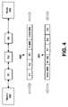
- FIG. 4illustrates packet addressing according to one embodiment of the invention.
- FIG. 5 aillustrates communication between a proxy source, a proxy repeater, a proxy agent and a proxy target according to one embodiment of the invention.
- FIG. 5 billustrates a transaction control between a proxy agent and a proxy target according to one embodiment of the invention.
- FIG. 5 cillustrates transaction control between a proxy repeater and a proxy agent according to one embodiment of the invention.
- FIG. 6illustrates one embodiment of a proxy protocol configured between a transaction/authentication layer (layers 4–5) and a plurality of network variables (layer 6).
- FIG. 1generally depicts a network over which a plurality of nodes 100 , 101 – 103 , 111 – 113 , 121 – 125 and 131 – 134 communicate.
- each of the nodesis comprised of a processor (e.g., a microcontroller or a micro-processor) and memory.
- each nodemay be configured to store, process and communicate (internally or with other nodes) code and data using machine-readable media such as magnetic disks, random access memory (“RAM”), read only memory (“ROM”), carrier wave signals, etc.
- RAMrandom access memory
- ROMread only memory
- carrier wave signalsetc.
- While particular embodiments of the inventionmay be implemented in software, alternative embodiments may implement the functions described herein using any combination of software, firmware and/or hardware.
- the nodes 100 , 101 – 103 , 111 – 113 , 121 – 125 and 131 – 134form a distributed control network such as the Lonworks® Network developed by Echelon® Corporation.
- each of the nodes 100 , 101 – 103 , 111 – 113 , 121 – 125 and 131 – 134may be programmed to perform a specific task.
- individual nodesmay be configured as proximity sensors, switches, motion detectors, relays, motor drives, and/or other types of instruments (e.g., utility meters).
- the individual nodes of this embodimentmay be programmed to work together as a whole to perform a complex control application such as running a manufacturing line or automating a building. It should be noted, however, that the underlying principles of the invention are not limited to any particular type of node or any particular network configuration or application.
- Certain embodiments of the inventionalso employ a proxy communication protocol to extend the communication range of a network channel when it is impractical to use conventional routers to do so. These embodiments may be particularly suited for network media where “breaking” a physical channel into multiple channels via routers is not practical or possible (e.g., radio frequency (RF), power lines, . . . etc).
- RFradio frequency
- certain nodesmay be configured/programmed to function as repeaters in addition to the other functions performed by those nodes (some examples of which are set forth above).
- a master node 100may be configured to automatically select surrounding nodes 101 – 103 , 111 – 113 , 121 – 125 and 131 – 134 to perform repeater functions based on the detected signal strength at those nodes.
- the master 100is programmed with device addresses of each of the nodes, which the master 100 uses to query each of the nodes 101 – 103 , 111 – 113 , 121 – 125 and 131 – 134 for signal strength data. After analyzing the signal strength data, the master 100 selects repeater candidates.
- FIGS. 2 a and 2 billustrate one embodiment of a method implemented by a master node to identify repeaters.
- the masterinitially attempts to communicate with all network nodes (e.g., by running through a list of node addresses stored in memory).
- the master node 100does not merely attempt to communicate but, rather, transmits “return signal strength” query to each of the surrounding nodes. Subsequently (at 215 ) the master node 100 receives a response from a subset of the nodes (i.e., from those nodes within the transmission range of the master 100 ). Each response includes an indication of signal quality when the “return signal strength” query was received at each of the nodes. In addition, in one particular embodiment, the master node 100 itself evaluates the signal quality of each node's response as it is received by the master 100 .
- two signal strength valuesare used by the master node 100 to evaluate the overall signal strength between it and each node on the network: an outgoing signal strength value (measured at the node); and an incoming signal strength value (measured at the master).
- the mastermay consider each value separately, may take the average of the two signal strength values or, alternatively, may weigh one value more heavily than the other.
- Various other techniques for evaluating the two signal strength valuesmay be employed while still complying with the underlying principles of the invention.
- Each of the nodes 101 – 103 , 111 – 113 , 121 – 125 and 131 – 134may measure “signal strength” using a variety of techniques. For example, in one embodiment, the overall carrier strength (e.g., amplitude) of the transmission is measured. Similarly, the signal-to-noise (S/N) ratio associated with the carrier signal may be calculated (i.e., by tracking the noise on the communication channel before and during the reception of the incoming signal). In addition, in one embodiment, the number of bit errors found in incoming data packet(s) may be calculated and used to provide an indication of the reliability of the communication channel between the node and the master.
- the overall carrier strengthe.g., amplitude
- S/Nsignal-to-noise
- S/Nsignal-to-noise
- the number of bit errors found in incoming data packet(s)may be calculated and used to provide an indication of the reliability of the communication channel between the node and the master.
- Certain techniques for measuring signal strengthmay be more appropriate than others depending on network conditions. For example, measuring overall carrier strength may be the most appropriate technique when the noise floor on the channel is below the receiver sensitivity. S/N Ratio may be more useful in cases where the noise on the channel is significant with respect to the signal level, and the number of errors corrected may be useful where other measures of signal strength are not available and/or there is an error correcting code available on the messages.
- the transmitter signal levelmay be purposely reduced to test the ability of a node to receive a signal.
- the transmitter signal levelcan be used as a measure of signal to noise ratio for the purposes of signal analysis. Use of this technique may require sending additional messages to probe for the level of reception.
- the masterperforms signal strength analysis (at 220 ) to determine which nodes in the subset are “first tier” repeater candidates (i.e., those repeaters which will be one transmission length or “hop” away from the master).
- the master's goalis not to select candidates with the highest measured signal strength but, rather, to select repeater candidates above some minimum (reliable) threshold value, T min , and below some maximum threshold value T max .
- both the outgoing signal strength value (measured at the node) and the incoming signal strength value (measured at the master)must be above the minimum and/or below the maximum threshold value for the particular node to be selected as a repeater.
- FIG. 3illustrates an exemplary signal strength relationship between the master 100 and the various nodes 101 – 103 , 111 – 113 , 121 – 125 and 131 – 134 shown in FIG. 1 .
- Nodes which are positioned further away from the master node 100 in FIG. 3have a relatively lower signal strength value in relation to the master 100 .
- nodes 101 , 121 , 122 , and 131all have relatively high signal strength values, above some maximum threshold 350 (as indicated). It would be inefficient for the master node 100 to select these nodes as repeater candidates, however, because they are not far enough away from the master node 100 to be useful as repeaters.
- nodes 103 , 112 – 113 , 124 – 125 and 132 – 134are electronically distant from the master node 100 and have signal strength values below some minimum threshold value 351 .
- the master 100will not initially select these nodes as repeaters because signal strength is so weak that they may prove to be unreliable. In fact, some or all may not even have received the master's 100 initial signal strength query.
- nodes 102 , 111 , and 123all have a signal strength value below the maximum threshold value 350 but above the minimum threshold value 351 . They are far enough away from the master 100 to make them efficient selections for repeater candidates, while—at the same time—their signal strength is high enough to indicate that they will be reliable as first tier repeaters. Accordingly, in the illustrated embodiment, the master node 100 initially selects nodes 102 , 111 , and 123 as first tier repeater candidates.
- the master 100transmits a “proxy return signal strength” command to each of the newly-selected first tier repeater candidates 102 , 111 , and 123 .
- the “proxy return signal strength” commandaccording to one embodiment is similar to the “return signal strength” command except that it instructs a node (e.g., nodes 102 , 111 , and 123 ) to collect signal strength data from other nodes (i.e., those nodes that did not respond when the master 100 initially attempted to communicate with all nodes at 210 ), and to communicate the results back to the master 100 .
- a nodee.g., nodes 102 , 111 , and 123
- it will be assumed that none of the nodes below the minimum threshold value 351 have respondedi.e., nodes 103 , 112 – 113 , 124 – 125 and 132 – 134 ).
- node 102queries node 103 for signal strength data. Subsequently, node 102 receives a response from node 103 which includes an indication of signal quality when the signal strength query was received at node 103 . In addition, in one embodiment, node 102 evaluates the signal quality of node 103 's response as it is received at node 102 . Accordingly, the “proxy return signal strength” command, like the “return signal strength” command, collects an incoming signal strength value (measured at node 102 ) as well as an outgoing signal strength value (measured at node 103 ), and transmits the result back to the master 100 .
- node 123collects proxy signal strength data from node 124 and node 111 collects proxy signal strength data from nodes 112 and/or 113 .
- a method variable ‘N,’which represents the particular tier of nodes under analysis is set equal to two. It should be noted, however, that this initialization is only used for the purpose of describing the underlying process set forth in FIGS. 2 a and 2 b . No such variable initialization is required for complying with the underlying principles of the invention.
- the master 100analyzes the proxy signal strength data to determine which (if any) of the newly-identified nodes should be configured as a second tier repeater. Once again, this decision may be based on where the signal strength values fall within predetermined minimum and maximum signal strength thresholds (as with selection of the first tier of repeaters described above). Thus, node 112 in the illustrated example may be too close to repeater candidate 111 to be properly selected as a repeater (i.e., signal strength may be above the maximum value) but node 113 may be a sufficient distance away to make it an ideal repeater candidate (i.e., within both the minimum and maximum threshold requirements).
- the master 100instructs each of the nodes in the second tier to collect proxy return signal strength data for nodes that have yet to be identified.
- the master 100receives the latest set of proxy return signal strength data and (if any new nodes have responded, determined at 255 ) analyzes the data to identify the next (e.g., the third) tier of repeater candidates.
- the master 100determines whether all nodes on the network have responded. If all nodes are accounted for, then the process is complete at 267 (i.e., all nodes are identified and all repeaters have been assigned). If, however, certain nodes have not responded, then the master 100 selects additional first tier repeater candidates in an effort to locate these nodes. Accordingly, the master 100 may select nodes which have signal strength values above the preset maximum 350 .
- the master 100may select any or all of nodes 101 , 121 – 122 , and 131 as new first tier candidates.
- the master 100selects nodes at a signal strength value in the vicinity of one half of the maximum threshold value 350 , to increase the likelihood of identifying additional nodes.
- the master 100instructs the new first tier repeater candidates to collect proxy return signal strength data from any nodes which have not yet responded. Thus, if node 131 is selected, it may attempt to collect signal strength data from nodes 132 – 134 ; and if node 121 is selected, it may attempt to collect signal strength data from node 125 . The master 100 continues to select new first tier candidates until new nodes have been identified (determined at 280 ).
- the process of searching through successive tiersbegins again at 230 , where the master 100 receives a new set of proxy return signal strength data from the new first tier repeater candidate(s). The master 100 then works its way through successive tiers as described above until no new nodes are responding (determined at 255 ). When all nodes have been identified (determined at 265 ) the process is complete (at 267 ).
- the master node 100is not initially programmed with device addresses of each of the nodes. Rather, in this embodiment, the master node 100 transmits a broadcast search message, requesting a response from any nodes within its transmission range. As nodes respond to the broadcast search message, the master node 100 stores their device addresses and selects certain nodes as repeaters as described above. Once selected by the master 100 , the various repeater candidates may also send broadcast messages to any nodes within their transmission range.
- the master node 100instructs the node not to respond to any subsequent broadcast search messages.
- the master node 100 or repeater candidatemay simply ignore subsequent responses to broadcast search message responses from nodes which have already responded.
- an address of each intermediate node through which a data packet will passis included in an address field in the data packet.
- a particular command 410e.g., a proxy return signal strength command
- the master 100transmits a data packet 400 containing a particular command 410 (e.g., a proxy return signal strength command)
- itincludes the addresses of each of the nodes, R 1 –R 3 , through which the packet will pass on its way to the destination node 405 .
- the destination node 405when the destination node 405 transmits data 420 (e.g., return signal strength or proxy return signal strength data) in response to the master's command 405 , it includes an address of each intermediate node, R 3 –R 1 , through which the data packet will pass on its way to the master 100 .
- data 420e.g., return signal strength or proxy return signal strength data
- each nodemay store a routing table in memory for routing data packets across the network.
- only the destination node address (and not the intermediate addresses)is incorporated in the data packet.
- Each node that receives the data packet in this embodimentchecks its routing table to determine the next node to which the packet should be routed (i.e., what the next intermediate node is).
- Embodiments of the system and method described hereinmay be configured to operate differently depending on the overall size of the network. For example, if the network is small enough so that probing all or most of the nodes does not require an unreasonable amount of time, then the best candidates for repeaters can be identified quickly by using the method set forth in FIGS. 2 a–b.
- one embodiment of the system and methodcan be used to quickly identify repeating nodes so that communications can be established with all nodes.
- the time/resource advantage of this embodimentis realized because fewer of the communicating nodes need to be probed to identify repeaters for the remaining nodes.
- additional available resourcescan be used to identify better repeater or alternate repeater candidates.
- repeatersdo not separate the physical medium over which they communicate into separate “channels.” Rather, in this particular embodiment, repeaters re-transmit data on the same channel on which they receive the data (hereinafter “disconnected channel”).
- disconnected channelthe same channel on which they receive the data
- nodesmay be configured as proxy sources 500 , proxy repeaters 510 , proxy agents 520 , and/or proxy targets 530 .
- a proxy source 500communicates with a proxy target 520 through a proxy repeater 510 and/or a proxy agent 520 .
- node designationsoccur automatically, after the nodes have been physically connected to the network (e.g., as described above with respect to repeater selection).
- a proxy source 500is any node originating a proxy transaction.
- the proxy source 500generates a proxy operation by attaching a proxy header to a standard (i.e., non-proxy) data/command packet.
- a standard data/command packetis a command requesting the value of a particular variable at a target node. If the target node is within transmission range of the source node (i.e., if no hops are required through intermediate nodes), then the source node simply transmits the packet directly to the target using the target's network address and waits for the response.
- the sourceattaches a proxy header to the packet, indicating one or more intermediate nodes (e.g., the proxy repeater 510 and the proxy agent 520 ) through which the data/command packet must pass to arrive at the target node (or in this case the “proxy” target node 530 ).
- one or more intermediate nodese.g., the proxy repeater 510 and the proxy agent 520
- Any nodes which are electrically positioned between the proxy source 500 and proxy agent 520may be configured as proxy repeaters 510 .
- a proxy repeater 510receives a data/command packet directed to the proxy target 530 it relays the message on to the next proxy repeater, or to the proxy agent 520 (if it is the last proxy repeater 510 in the chain).
- a proxy agent 520is any node which communicates directly with the proxy target 530 .
- the proxy agent 520transmits a standard data/command packet to the proxy target 530 , rather than a proxy packet (i.e., one with a “proxy” header).
- the commandOnce the command has been received and processed at the proxy target 530 , it generates a response packet addressed to the proxy agent 520 containing the data requested by the proxy source 500 .
- the proxy agent 520forwards the message to the proxy repeater 510 (by attaching the proxy repeater's address to the packet) which, in turn, forwards the message to the proxy source 500 .
- a packet transmitted by the proxy source 500includes an address header with an address of each node through which the packet must pass to arrive at the proxy target 530 .
- Each node in the transmission pathreceives the packet, strips its own address from the header and forwards the packet on to the next node in the path (identified by the next address in the header).
- Each noderemembers (i.e., stores in memory) the address of the node from which it received the packet.
- the proxy target 530After processing the packet (e.g., executing the command and collecting any requested data) the proxy target 530 transmits a response packet back to the proxy agent 520 .
- the response packetincludes only the proxy agent's 520 's address.
- the proxy agent 520which previously stored the address of the proxy repeater 510 in memory, uses this address to forward the packet back to the proxy repeater 510 ; which, in turn, transmits the packet to the proxy source 500 using the address of the proxy source 500 which the proxy repeater 510 previously stored in memory.
- addressesare not stripped from data packets as they pass from one node to the next. Rather, in this embodiment, a packet is transmitted from the proxy source 500 through to the proxy target 530 with an address of each node in the transmission path embedded in the packet's header.
- the packet's headeralso includes a counter/pointer value which points to the next address in the transmission path. Each node that receives the packet increments (or decrements, depending on the particular algorithm) the counter/pointer value so that it points the next address in the packet's header.
- the proxy target 530when the proxy target 530 receives the packet, it resets the counter and transmits a response packet containing each node address (e.g., in reverse order).
- a nodemay retransmit a data/command packet if it does not receive a response for a predetermined period of time.
- a message ( 3 ) between the proxy agent 520 and proxy target 530is blocked (e.g., due to interference on the network)
- the proxy agent 520will retransmit the message ( 4 ) if it does not receive a response from the proxy target 530 after a predefined period of time.
- the retry timing(i.e., the timing for retransmitting a lost message) employed at each of the nodes is highly configurable and can be programmed based on a variety of network variables (e.g., the number of hops between the node and the proxy source 500 and/or proxy target 530 ).
- the proxy agent 520may use conventional timer and retry values to communicate with the proxy target 530 (e.g., 3 retries spaced at 192 milliseconds on a contention-free channel), whereas the proxy repeater 510 may use different proxy timer and retry values to communicate with the proxy agent 520 and/or the proxy source 500 (e.g., 6 retries spaced at 960 milliseconds).
- the transaction control values to be used for retransmitting a particular messageare specified by the proxy source 500 in the data/control packet message header (e.g., the proxy portion of the header).
- the set of control values used at the proxy source 500 and/or proxy repeater 510specify an increased number of retries relative to the number of retries specified for the proxy agent 520 .
- the number of retriesmay be configured to increase with increasing distance from the proxy agent 520 .
- the proxy source 500provides the proxy repeaters with the number of retries for the last repeater to use. Each repeater prior to the last simply uses one more retry than the next. This value may be computed by adding the remaining repeater count to the retry count.
- each of the network nodesmay be configured with different retry timer values. In one embodiment, however, the same retry timer value is used for each of the proxy repeaters 510 .
- the timer value used in this embodimentmay be set to be longer than the entire transaction time of the agent/target transaction plus the round trip back to the source.
- Various data service levelsmay be defined to operate within the system described herein. These include, but are not limited to, an unacknowledged message service (“unackd”) where messages transmitted from a source node to a target node do not require a response from the target; an unacknowledged repeat message service (“unackd-rpt”) which is an unacknowledged message transmitted a specified number of times; an acknowledged message (“ackd”) wherein the source waits for a simple acknowledgement (or confirmation) transmitted from the target node after receipt of the message; and a request/response message (“request/response”) wherein the source waits for a response containing data related to the actual processing of the request in the target node.
- unackd message servicewhere messages transmitted from a source node to a target node do not require a response from the target
- unackd-rptwhich is an unacknowledged message transmitted a specified number of times
- an acknowledged message(“ackd”) wherein the source waits for
- FIG. 5 billustrates an exemplary message sequence when a transmission error occurs between the proxy agent 520 and the proxy target 530 . More particularly, message 3 is lost on its way from the proxy agent 520 to the proxy target 530 .
- the proxy agent 520after not receiving a response from the proxy target 530 for a predefined retry time period, retransmits the message (message 4 ) and receives a response (message 5 ).
- the proxy repeater 510 in this embodimentdoes not retransmit message 2 while waiting for message 6 because its retry timer is set to a longer period than the proxy agent's 520 's.
- FIG. 5 cillustrates an exemplary message sequence in when an intermediate response (message 5 ) transmitted from the proxy agent 520 to the proxy repeater 510 is lost.
- the proxy repeater 510transmits message 2 (e.g., a request/response message) to the proxy agent 520 and, after waiting for a response for the retry time period, retransmits the message (illustrated as message 7 ).
- the proxy agent 520then retransmits the response message (message 8 ) to the proxy repeater 510 .
- nodesmay be programmed to store messages and message responses in memory.
- the proxy repeater 510retransmits its message (message 7 )
- the proxy agent 520can immediately retransmit the response (message 8 ) which it previously stored in memory.
- message 6is superfluous, but harmless (i.e., the proxy repeater 510 may be configured to ignore it).
- the proxy source's 500 's retry timermay be set long enough to prevent this re-transmission.
- exponentially increasing retry timers in this mannermay become problematic in certain situations (e.g., with a large number of repeaters).
- the source address of the response received by the proxy source 500 from the first repeater 510will be that of the repeater, not the proxy target 530 .
- each proxy repeater/agentbuffers any responses it receives. This way, if a response is lost in transmission (e.g., message 5 of FIG. 5 c ), and a request retry is received, it will not be necessary to re-fetch the response from the downstream path.
- this buffering featureis accomplished at a proxy layer configured in the network protocol stack.
- the proxy layer 620resides between a transaction/authentication layer 630 and a network variables layer 610 . As indicated, these layers roughly correspond to the transport/session layers (L 4 – 5 ) and the presentation layer (L 6 ) of the Open System Interconnection (“OSI”) model.
- OSIOpen System Interconnection
- an agent/target transactionmay be a different type of transaction from the corresponding repeater/agent transaction.
- the repeater/agent transactionmay be a request/response message whereas the agent/target transaction may be a acknowledged message multicast to a group of nodes.
- the response transmitted from the agent to the repeatermay be a simple one-byte completion code conveying success or failure of the underlying transaction.
- the agentcould send an acknowledged multicast to a group and upon receiving all the acknowledgements, send a “success” response upstream.
- a “failure” responsemay be sent upstream along with the repeater index of the node detecting the failure.
- message prioritiesmay be defined.
- prioritymay be strictly inherited. For example, if a proxy source 500 defines a priority, then priority is used by all proxy repeaters 510 and the proxy agent 520 .
- authenticationlike priority, may be inherited.
- each hopmay be authenticated separately.
- the first proxy repeater 510may challenge the proxy source 500 and receive a successful reply before relaying the proxied message on to the next proxy repeater 510 or proxy agent 520 .
- an authentication keymay be embedded in a proxy message header for the proxy agent 520 to use when communicating with the proxy target 530 .
- This configurationhandles the case where the agent 520 and target 530 have different authentication keys (presumably only temporarily).
- the proxy source 500ensures that authentication keys are the same in the intermediate points of the proxy chain (e.g., the proxy repeaters 510 ) before using authentication.
- the proxy agent 520 of one embodimentis capable of using the authentication key only for that outgoing transaction rather than changing its own key.
- the authentication key passed down for such messagesmay be in the form of a key increment.
- the proxy agent 520will use its own key and add the key increment to it to derive the proxy target's 530 's key. This feature will provide secure authentication without the need for transmitting the authentication key over a non-secure channel.
- each proxy repeater 510may serve as both a proxy agent and a proxy repeater.
- a proxy repeater 510identifies an unacknowledged broadcast or group message as the message to be delivered by the proxy agent 520 (by peeking ahead to the end of the proxy header), it first sends the message as if it were a proxy agent 520 and then relays the message on to the next proxy repeater 510 or proxy agent 520 .
- any given nodemay receive such a multicast more than one time. Therefore, in one embodiment, it is necessary that such multicasts be idempotent.
- proxy repeaters 510 and proxy agent 520 of this embodimentmay use the same domain ID as the proxy source 500 . Accordingly, proxy repeaters 510 and proxy agents 520 may be commissioned with a domain ID topologically, closest to the proxy source 500 first.
- the proxy source 500uses unicast (e.g., subnet/node) addressing to communicate with the first proxy repeater 520 (although other addressing modes may be used as well).
- the proxy header used in this embodimentmay contain only unicast addresses so all repeater-to-repeater and repeater-to-agent downstream messages are unicast.
- the channelprovides two paths, a primary and alternate path, and the path to be used at each hop is encoded on a per-hop basis in the proxy header.
- the proxy source 500may be supplied with a routing table containing for each unicast address (subnet/node or node ID), a list of repeaters 510 and the agent 520 to use to reach that address (e.g., perhaps a null set), as well as a first choice path to use at each hop.
- the listmay contain the set of agents 520 to which the multicast is to be delivered.
- Embodiments of the inventioninclude various steps, which have been described above.
- the stepsmay be embodied in machine-executable instructions.
- the instructionscan be used to cause a general-purpose or special-purpose processor to perform certain steps.
- these stepsmay be performed by specific hardware components that contain hardwired logic for performing the steps, or by any combination of programmed computer components and custom hardware components.
- Embodiments of the inventionmay also be provided as a machine-readable medium for storing the machine-executable instructions.
- the machine-readable mediummay include, but is not limited to, floppy diskettes, optical disks, CD-ROMs, and magneto-optical disks, ROMs, RAMs, EPROMs, EEPROMs, magnet or optical cards, propagation media or other type of media/machine-readable medium suitable for storing electronic instructions.
- the present inventionmay be downloaded as a computer program which may be transferred from a remote computer (e.g., a server) to a requesting computer (e.g., a client) by way of data signals embodied in a carrier wave or other propagation medium via a communication link (e.g., a modem or network connection).
- a remote computere.g., a server
- a requesting computere.g., a client
- a communication linke.g., a modem or network connection
- FIG. 1illustrates a terrestrial network configuration
- various non-terrestrial configurationssuch as radio frequency broadcast, satellite broadcast, personal communication services (“PCS”), Global System for Mobile Communications (“GSM”), and cellular (including code division multiple access (“CDMA”) and time division multiple access (“TDMA”)) may be implemented while still complying with the underlying principles of the invention.
- PCSpersonal communication services
- GSMGlobal System for Mobile Communications
- CDMAcode division multiple access
- TDMAtime division multiple access
- one embodiment of the inventionemploys a heterogeneous network configuration, including both terrestrial and non-terrestrial components.
- proxy layeris illustrated in FIG. 6 between the transaction/authentication layer 630 and the network variables layer 610 , alternate embodiments may incorporate the same proxy functionality at other layers in the OSI model.
- the network functions described aboveare implemented at the network/addressing layer (i.e., OSI layer 3 ) 640 .
- transaction control and authenticationwould be implemented on an end-to-end basis (i.e., between the proxy source 500 and the proxy target 530 ) rather than on an individual node-to-node basis as described above.
Landscapes
- Engineering & Computer Science (AREA)
- Computer Networks & Wireless Communication (AREA)
- Signal Processing (AREA)
- Mobile Radio Communication Systems (AREA)
- Communication Control (AREA)
- Data Exchanges In Wide-Area Networks (AREA)
Abstract
Description
Claims (8)
Priority Applications (2)
| Application Number | Priority Date | Filing Date | Title |
|---|---|---|---|
| US09/638,169US7103016B1 (en) | 2000-08-11 | 2000-08-11 | System and method for providing transaction control on a data network |
| EP01303672.8AEP1179909B1 (en) | 2000-08-11 | 2001-04-20 | A system and method for providing transaction control on a data network |
Applications Claiming Priority (1)
| Application Number | Priority Date | Filing Date | Title |
|---|---|---|---|
| US09/638,169US7103016B1 (en) | 2000-08-11 | 2000-08-11 | System and method for providing transaction control on a data network |
Publications (1)
| Publication Number | Publication Date |
|---|---|
| US7103016B1true US7103016B1 (en) | 2006-09-05 |
Family
ID=24558922
Family Applications (1)
| Application Number | Title | Priority Date | Filing Date |
|---|---|---|---|
| US09/638,169Expired - LifetimeUS7103016B1 (en) | 2000-08-11 | 2000-08-11 | System and method for providing transaction control on a data network |
Country Status (2)
| Country | Link |
|---|---|
| US (1) | US7103016B1 (en) |
| EP (1) | EP1179909B1 (en) |
Cited By (64)
| Publication number | Priority date | Publication date | Assignee | Title |
|---|---|---|---|---|
| US20030061337A1 (en)* | 2001-09-27 | 2003-03-27 | Kabushiki Kaisha Toshiba | Data transfer scheme using caching technique for reducing network load |
| US20030126077A1 (en)* | 2001-08-16 | 2003-07-03 | Jiri Kantor | Message brokering |
| US20030126229A1 (en)* | 2001-08-16 | 2003-07-03 | Jiri Kantor | Message brokering |
| US20060244631A1 (en)* | 2001-09-13 | 2006-11-02 | M & Fc Holding, Llc | Modular wireless fixed network for wide-area metering data collection and meter module apparatus |
| US20070174485A1 (en)* | 2006-01-24 | 2007-07-26 | Novell, Inc. | Content distribution via keys |
| US20080071911A1 (en)* | 2006-08-31 | 2008-03-20 | Holbrook Kenneth J | Orchestration manager |
| US20080071930A1 (en)* | 2006-09-01 | 2008-03-20 | Holbrook Kenneth J | Native network transport |
| US20080074285A1 (en)* | 2006-08-31 | 2008-03-27 | Guthrie Kevin D | Interface between meter and application (IMA) |
| US20090104906A1 (en)* | 2007-10-19 | 2009-04-23 | Samsung Electronics Co., Ltd. | Logical connection establishment method for mobile terminal |
| US20110004801A1 (en)* | 2000-07-05 | 2011-01-06 | Darrell Duffy | System and method for selecting repeaters |
| USD648642S1 (en) | 2009-10-21 | 2011-11-15 | Lennox Industries Inc. | Thin cover plate for an electronic system controller |
| USD648641S1 (en) | 2009-10-21 | 2011-11-15 | Lennox Industries Inc. | Thin cover plate for an electronic system controller |
| US8239066B2 (en) | 2008-10-27 | 2012-08-07 | Lennox Industries Inc. | System and method of use for a user interface dashboard of a heating, ventilation and air conditioning network |
| US8255086B2 (en) | 2008-10-27 | 2012-08-28 | Lennox Industries Inc. | System recovery in a heating, ventilation and air conditioning network |
| US8260444B2 (en) | 2010-02-17 | 2012-09-04 | Lennox Industries Inc. | Auxiliary controller of a HVAC system |
| US8295981B2 (en) | 2008-10-27 | 2012-10-23 | Lennox Industries Inc. | Device commissioning in a heating, ventilation and air conditioning network |
| US8352081B2 (en) | 2008-10-27 | 2013-01-08 | Lennox Industries Inc. | Communication protocol system and method for a distributed-architecture heating, ventilation and air conditioning network |
| US8352080B2 (en) | 2008-10-27 | 2013-01-08 | Lennox Industries Inc. | Communication protocol system and method for a distributed-architecture heating, ventilation and air conditioning network |
| US8433446B2 (en) | 2008-10-27 | 2013-04-30 | Lennox Industries, Inc. | Alarm and diagnostics system and method for a distributed-architecture heating, ventilation and air conditioning network |
| US8437878B2 (en) | 2008-10-27 | 2013-05-07 | Lennox Industries Inc. | Alarm and diagnostics system and method for a distributed architecture heating, ventilation and air conditioning network |
| US8437877B2 (en) | 2008-10-27 | 2013-05-07 | Lennox Industries Inc. | System recovery in a heating, ventilation and air conditioning network |
| US8442693B2 (en) | 2008-10-27 | 2013-05-14 | Lennox Industries, Inc. | System and method of use for a user interface dashboard of a heating, ventilation and air conditioning network |
| US8452906B2 (en) | 2008-10-27 | 2013-05-28 | Lennox Industries, Inc. | Communication protocol system and method for a distributed-architecture heating, ventilation and air conditioning network |
| US8452456B2 (en) | 2008-10-27 | 2013-05-28 | Lennox Industries Inc. | System and method of use for a user interface dashboard of a heating, ventilation and air conditioning network |
| US8463442B2 (en) | 2008-10-27 | 2013-06-11 | Lennox Industries, Inc. | Alarm and diagnostics system and method for a distributed architecture heating, ventilation and air conditioning network |
| US8463443B2 (en) | 2008-10-27 | 2013-06-11 | Lennox Industries, Inc. | Memory recovery scheme and data structure in a heating, ventilation and air conditioning network |
| US8543243B2 (en) | 2008-10-27 | 2013-09-24 | Lennox Industries, Inc. | System and method of use for a user interface dashboard of a heating, ventilation and air conditioning network |
| US8548630B2 (en) | 2008-10-27 | 2013-10-01 | Lennox Industries, Inc. | Alarm and diagnostics system and method for a distributed-architecture heating, ventilation and air conditioning network |
| US20130265332A1 (en)* | 2012-04-10 | 2013-10-10 | Canon Kabushiki Kaisha | Information processing apparatus, control method of information processing apparatus, and storage medium storing program |
| US8560125B2 (en) | 2008-10-27 | 2013-10-15 | Lennox Industries | Communication protocol system and method for a distributed-architecture heating, ventilation and air conditioning network |
| US8564400B2 (en) | 2008-10-27 | 2013-10-22 | Lennox Industries, Inc. | Communication protocol system and method for a distributed-architecture heating, ventilation and air conditioning network |
| US8600559B2 (en) | 2008-10-27 | 2013-12-03 | Lennox Industries Inc. | Method of controlling equipment in a heating, ventilation and air conditioning network |
| US8600558B2 (en) | 2008-10-27 | 2013-12-03 | Lennox Industries Inc. | System recovery in a heating, ventilation and air conditioning network |
| US8615326B2 (en) | 2008-10-27 | 2013-12-24 | Lennox Industries Inc. | System and method of use for a user interface dashboard of a heating, ventilation and air conditioning network |
| US8655490B2 (en) | 2008-10-27 | 2014-02-18 | Lennox Industries, Inc. | System and method of use for a user interface dashboard of a heating, ventilation and air conditioning network |
| US8655491B2 (en) | 2008-10-27 | 2014-02-18 | Lennox Industries Inc. | Alarm and diagnostics system and method for a distributed architecture heating, ventilation and air conditioning network |
| US8661165B2 (en) | 2008-10-27 | 2014-02-25 | Lennox Industries, Inc. | Device abstraction system and method for a distributed architecture heating, ventilation and air conditioning system |
| US8694164B2 (en) | 2008-10-27 | 2014-04-08 | Lennox Industries, Inc. | Interactive user guidance interface for a heating, ventilation and air conditioning system |
| US8725298B2 (en) | 2008-10-27 | 2014-05-13 | Lennox Industries, Inc. | Alarm and diagnostics system and method for a distributed architecture heating, ventilation and conditioning network |
| US8744629B2 (en) | 2008-10-27 | 2014-06-03 | Lennox Industries Inc. | System and method of use for a user interface dashboard of a heating, ventilation and air conditioning network |
| US8762666B2 (en) | 2008-10-27 | 2014-06-24 | Lennox Industries, Inc. | Backup and restoration of operation control data in a heating, ventilation and air conditioning network |
| US8774210B2 (en) | 2008-10-27 | 2014-07-08 | Lennox Industries, Inc. | Communication protocol system and method for a distributed-architecture heating, ventilation and air conditioning network |
| US8788100B2 (en) | 2008-10-27 | 2014-07-22 | Lennox Industries Inc. | System and method for zoning a distributed-architecture heating, ventilation and air conditioning network |
| US8798796B2 (en) | 2008-10-27 | 2014-08-05 | Lennox Industries Inc. | General control techniques in a heating, ventilation and air conditioning network |
| US8802981B2 (en) | 2008-10-27 | 2014-08-12 | Lennox Industries Inc. | Flush wall mount thermostat and in-set mounting plate for a heating, ventilation and air conditioning system |
| US8855825B2 (en) | 2008-10-27 | 2014-10-07 | Lennox Industries Inc. | Device abstraction system and method for a distributed-architecture heating, ventilation and air conditioning system |
| US8874815B2 (en) | 2008-10-27 | 2014-10-28 | Lennox Industries, Inc. | Communication protocol system and method for a distributed architecture heating, ventilation and air conditioning network |
| US8892797B2 (en) | 2008-10-27 | 2014-11-18 | Lennox Industries Inc. | Communication protocol system and method for a distributed-architecture heating, ventilation and air conditioning network |
| US20150061892A1 (en)* | 2004-05-27 | 2015-03-05 | Google Inc. | Measuring quantitative environmental data within a wireless sensor system |
| US8977794B2 (en) | 2008-10-27 | 2015-03-10 | Lennox Industries, Inc. | Communication protocol system and method for a distributed-architecture heating, ventilation and air conditioning network |
| US8994539B2 (en) | 2008-10-27 | 2015-03-31 | Lennox Industries, Inc. | Alarm and diagnostics system and method for a distributed-architecture heating, ventilation and air conditioning network |
| US9152155B2 (en) | 2008-10-27 | 2015-10-06 | Lennox Industries Inc. | Device abstraction system and method for a distributed-architecture heating, ventilation and air conditioning system |
| US9261888B2 (en) | 2008-10-27 | 2016-02-16 | Lennox Industries Inc. | System and method of use for a user interface dashboard of a heating, ventilation and air conditioning network |
| US9268345B2 (en) | 2008-10-27 | 2016-02-23 | Lennox Industries Inc. | System and method of use for a user interface dashboard of a heating, ventilation and air conditioning network |
| US9325517B2 (en) | 2008-10-27 | 2016-04-26 | Lennox Industries Inc. | Device abstraction system and method for a distributed-architecture heating, ventilation and air conditioning system |
| US9377768B2 (en) | 2008-10-27 | 2016-06-28 | Lennox Industries Inc. | Memory recovery scheme and data structure in a heating, ventilation and air conditioning network |
| US9432208B2 (en) | 2008-10-27 | 2016-08-30 | Lennox Industries Inc. | Device abstraction system and method for a distributed architecture heating, ventilation and air conditioning system |
| US9632490B2 (en) | 2008-10-27 | 2017-04-25 | Lennox Industries Inc. | System and method for zoning a distributed architecture heating, ventilation and air conditioning network |
| US9651925B2 (en) | 2008-10-27 | 2017-05-16 | Lennox Industries Inc. | System and method for zoning a distributed-architecture heating, ventilation and air conditioning network |
| US9678486B2 (en) | 2008-10-27 | 2017-06-13 | Lennox Industries Inc. | Device abstraction system and method for a distributed-architecture heating, ventilation and air conditioning system |
| US10165488B2 (en)* | 2016-06-16 | 2018-12-25 | Yandex Europe Ag | Method of and system for processing a transaction request in distributed data processing systems |
| US10200476B2 (en) | 2011-10-18 | 2019-02-05 | Itron, Inc. | Traffic management and remote configuration in a gateway-based network |
| US10664792B2 (en) | 2008-05-16 | 2020-05-26 | Google Llc | Maintaining information facilitating deterministic network routing |
| US10813030B2 (en) | 2005-07-01 | 2020-10-20 | Google Llc | Maintaining information facilitating deterministic network routing |
Families Citing this family (3)
| Publication number | Priority date | Publication date | Assignee | Title |
|---|---|---|---|---|
| US9001921B1 (en) | 2004-02-18 | 2015-04-07 | Marvell International Ltd. | Circuits, architectures, methods, algorithms, software, and systems for improving the reliability of data communications having time-dependent fluctuations |
| WO2006024320A1 (en)* | 2004-08-31 | 2006-03-09 | Telefonaktiebolaget Lm Ericsson (Publ) | Data unit sender and data unit relay device |
| US8520648B2 (en)* | 2010-06-14 | 2013-08-27 | Intel Corporation | Beacon transmission techniques in directional wireless networks |
Citations (25)
| Publication number | Priority date | Publication date | Assignee | Title |
|---|---|---|---|---|
| US4270029A (en) | 1978-03-23 | 1981-05-26 | Kokusai Denshin Denwa Kabushiki Kaisha | Selection system for digital signal repeaters |
| US5341398A (en) | 1993-02-25 | 1994-08-23 | Motorola, Inc. | Method for repeaters to adaptively digitally code received analog information |
| US5422929A (en) | 1991-11-13 | 1995-06-06 | Txport, Inc. | Telephone line repeater and method of testing same |
| US5457687A (en)* | 1993-09-02 | 1995-10-10 | Network Equipment Technologies, Inc. | Method and apparatus for backward explicit congestion notification (BECN) in an ATM network |
| US5793842A (en) | 1995-02-27 | 1998-08-11 | Schloemer; Jerry R. | System and method of call routing and connection in a mobile (remote) radio telephone system |
| US5815667A (en)* | 1995-11-28 | 1998-09-29 | Ncr Corporation | Circuits and methods for intelligent acknowledgement based flow control in a processing system network |
| US5822523A (en)* | 1996-02-01 | 1998-10-13 | Mpath Interactive, Inc. | Server-group messaging system for interactive applications |
| US5850605A (en) | 1996-11-05 | 1998-12-15 | Motorola, Inc. | Method and apparatus for dynamically grouping transmitters for message transmission in a communication system |
| US5878352A (en) | 1996-12-20 | 1999-03-02 | Motorola, Inc. | Apparatus and method for selecting a transmitter for directed message delivery |
| US5883884A (en) | 1996-04-22 | 1999-03-16 | Roger F. Atkinson | Wireless digital communication system having hierarchical wireless repeaters with autonomous hand-off |
| US5905871A (en)* | 1996-10-10 | 1999-05-18 | Lucent Technologies Inc. | Method of multicasting |
| US5917820A (en)* | 1996-06-10 | 1999-06-29 | Cisco Technology, Inc. | Efficient packet forwarding arrangement for routing packets in an internetwork |
| US5919250A (en)* | 1995-05-12 | 1999-07-06 | Kabushiki Kaisha Toshiba | Data transmission system used for plant control and based on local area network |
| US5920818A (en) | 1996-12-03 | 1999-07-06 | Telefonaktiebolaget L M Ericsson (Publ) | Apparatus and method for controlling communications in a multi-network, wireless communication system |
| US6125279A (en) | 1998-01-07 | 2000-09-26 | Motorola, Inc. | Method and apparatus for extending coverage in a cellular communication system |
| US6269080B1 (en)* | 1999-04-13 | 2001-07-31 | Glenayre Electronics, Inc. | Method of multicast file distribution and synchronization |
| US6310892B1 (en)* | 1994-11-21 | 2001-10-30 | Oracle Corporation | Reliable connectionless network protocol |
| US6377805B1 (en) | 1999-08-04 | 2002-04-23 | International Business Machines Corporation | Maintaining data communication through neighboring mobile units during handoff |
| US20020065094A1 (en) | 1999-12-29 | 2002-05-30 | Schmutz Thomas R. | Backhaul power control system in a wireless repeater |
| US6459899B1 (en) | 1998-09-14 | 2002-10-01 | Jerry R. Schloemer | Cellular radio routing system |
| US6466905B1 (en) | 1999-11-30 | 2002-10-15 | Motorola, Inc. | Differentiation of error conditions in digital voice communication systems |
| US6507562B1 (en)* | 1998-06-30 | 2003-01-14 | Sun Microsystems, Inc. | Dynamic optimization for receivers using distance between a repair head and a member station in a repair group for receivers having a closely knit topological arrangement to locate repair heads near the member stations which they serve in tree based repair in reliable multicast protocol |
| US6515994B1 (en)* | 1998-07-30 | 2003-02-04 | Lucent Technologies Inc. | Method of communication in a communications network and apparatus therefor |
| US6587974B1 (en)* | 1999-11-19 | 2003-07-01 | Tyco Telecommunications (Us) Inc. | Method for fault detection and fast protection switching in transmission systems |
| US6621833B1 (en)* | 1999-12-17 | 2003-09-16 | World Com, Inc. | Method and system for efficiently passing the silence or unused status of a DSO channel through a DSO switch matrix and a data switch |
Family Cites Families (3)
| Publication number | Priority date | Publication date | Assignee | Title |
|---|---|---|---|---|
| GB9223890D0 (en)* | 1992-11-13 | 1993-01-06 | Ncr Int Inc | Wireless local area network system |
| US5699367A (en) | 1995-12-29 | 1997-12-16 | Telefonaktiebolaget Lm Ericsson | Concatenated error detection coding and packet numbering for hierarchical ARQ schemes |
| US6181704B1 (en)* | 1997-08-29 | 2001-01-30 | Intel Corporation | Method and apparatus for input/output link retry, failure and recovery in a computer network |
- 2000
- 2000-08-11USUS09/638,169patent/US7103016B1/ennot_activeExpired - Lifetime
- 2001
- 2001-04-20EPEP01303672.8Apatent/EP1179909B1/ennot_activeExpired - Lifetime
Patent Citations (25)
| Publication number | Priority date | Publication date | Assignee | Title |
|---|---|---|---|---|
| US4270029A (en) | 1978-03-23 | 1981-05-26 | Kokusai Denshin Denwa Kabushiki Kaisha | Selection system for digital signal repeaters |
| US5422929A (en) | 1991-11-13 | 1995-06-06 | Txport, Inc. | Telephone line repeater and method of testing same |
| US5341398A (en) | 1993-02-25 | 1994-08-23 | Motorola, Inc. | Method for repeaters to adaptively digitally code received analog information |
| US5457687A (en)* | 1993-09-02 | 1995-10-10 | Network Equipment Technologies, Inc. | Method and apparatus for backward explicit congestion notification (BECN) in an ATM network |
| US6310892B1 (en)* | 1994-11-21 | 2001-10-30 | Oracle Corporation | Reliable connectionless network protocol |
| US5793842A (en) | 1995-02-27 | 1998-08-11 | Schloemer; Jerry R. | System and method of call routing and connection in a mobile (remote) radio telephone system |
| US5919250A (en)* | 1995-05-12 | 1999-07-06 | Kabushiki Kaisha Toshiba | Data transmission system used for plant control and based on local area network |
| US5815667A (en)* | 1995-11-28 | 1998-09-29 | Ncr Corporation | Circuits and methods for intelligent acknowledgement based flow control in a processing system network |
| US5822523A (en)* | 1996-02-01 | 1998-10-13 | Mpath Interactive, Inc. | Server-group messaging system for interactive applications |
| US5883884A (en) | 1996-04-22 | 1999-03-16 | Roger F. Atkinson | Wireless digital communication system having hierarchical wireless repeaters with autonomous hand-off |
| US5917820A (en)* | 1996-06-10 | 1999-06-29 | Cisco Technology, Inc. | Efficient packet forwarding arrangement for routing packets in an internetwork |
| US5905871A (en)* | 1996-10-10 | 1999-05-18 | Lucent Technologies Inc. | Method of multicasting |
| US5850605A (en) | 1996-11-05 | 1998-12-15 | Motorola, Inc. | Method and apparatus for dynamically grouping transmitters for message transmission in a communication system |
| US5920818A (en) | 1996-12-03 | 1999-07-06 | Telefonaktiebolaget L M Ericsson (Publ) | Apparatus and method for controlling communications in a multi-network, wireless communication system |
| US5878352A (en) | 1996-12-20 | 1999-03-02 | Motorola, Inc. | Apparatus and method for selecting a transmitter for directed message delivery |
| US6125279A (en) | 1998-01-07 | 2000-09-26 | Motorola, Inc. | Method and apparatus for extending coverage in a cellular communication system |
| US6507562B1 (en)* | 1998-06-30 | 2003-01-14 | Sun Microsystems, Inc. | Dynamic optimization for receivers using distance between a repair head and a member station in a repair group for receivers having a closely knit topological arrangement to locate repair heads near the member stations which they serve in tree based repair in reliable multicast protocol |
| US6515994B1 (en)* | 1998-07-30 | 2003-02-04 | Lucent Technologies Inc. | Method of communication in a communications network and apparatus therefor |
| US6459899B1 (en) | 1998-09-14 | 2002-10-01 | Jerry R. Schloemer | Cellular radio routing system |
| US6269080B1 (en)* | 1999-04-13 | 2001-07-31 | Glenayre Electronics, Inc. | Method of multicast file distribution and synchronization |
| US6377805B1 (en) | 1999-08-04 | 2002-04-23 | International Business Machines Corporation | Maintaining data communication through neighboring mobile units during handoff |
| US6587974B1 (en)* | 1999-11-19 | 2003-07-01 | Tyco Telecommunications (Us) Inc. | Method for fault detection and fast protection switching in transmission systems |
| US6466905B1 (en) | 1999-11-30 | 2002-10-15 | Motorola, Inc. | Differentiation of error conditions in digital voice communication systems |
| US6621833B1 (en)* | 1999-12-17 | 2003-09-16 | World Com, Inc. | Method and system for efficiently passing the silence or unused status of a DSO channel through a DSO switch matrix and a data switch |
| US20020065094A1 (en) | 1999-12-29 | 2002-05-30 | Schmutz Thomas R. | Backhaul power control system in a wireless repeater |
Cited By (83)
| Publication number | Priority date | Publication date | Assignee | Title |
|---|---|---|---|---|
| US8340572B2 (en)* | 2000-07-05 | 2012-12-25 | Echelon Corporation | System and method for selecting repeaters |
| US20110004801A1 (en)* | 2000-07-05 | 2011-01-06 | Darrell Duffy | System and method for selecting repeaters |
| US7653679B2 (en) | 2001-08-16 | 2010-01-26 | Sun Microsystems, Inc. | Systems and methods for multi-stage message brokering |
| US20030126077A1 (en)* | 2001-08-16 | 2003-07-03 | Jiri Kantor | Message brokering |
| US20030126229A1 (en)* | 2001-08-16 | 2003-07-03 | Jiri Kantor | Message brokering |
| US7523164B2 (en)* | 2001-08-16 | 2009-04-21 | Sun Microsystems, Inc. | Systems and methods for transaction messaging brokering |
| US20060244631A1 (en)* | 2001-09-13 | 2006-11-02 | M & Fc Holding, Llc | Modular wireless fixed network for wide-area metering data collection and meter module apparatus |
| US8269651B2 (en)* | 2001-09-13 | 2012-09-18 | Sensus Usa Inc. | Modular wireless fixed network for wide-area metering data collection and meter module apparatus |
| US20030061337A1 (en)* | 2001-09-27 | 2003-03-27 | Kabushiki Kaisha Toshiba | Data transfer scheme using caching technique for reducing network load |
| US7441248B2 (en)* | 2001-09-27 | 2008-10-21 | Kabushiki Kaisha Toshiba | Data transfer scheme using caching technique for reducing network load |
| US10861316B2 (en) | 2004-05-27 | 2020-12-08 | Google Llc | Relaying communications in a wireless sensor system |
| US10229586B2 (en) | 2004-05-27 | 2019-03-12 | Google Llc | Relaying communications in a wireless sensor system |
| US20150061892A1 (en)* | 2004-05-27 | 2015-03-05 | Google Inc. | Measuring quantitative environmental data within a wireless sensor system |
| US10015743B2 (en) | 2004-05-27 | 2018-07-03 | Google Llc | Relaying communications in a wireless sensor system |
| US10395513B2 (en) | 2004-05-27 | 2019-08-27 | Google Llc | Relaying communications in a wireless sensor system |
| US10565858B2 (en) | 2004-05-27 | 2020-02-18 | Google Llc | Wireless transceiver |
| US10573166B2 (en) | 2004-05-27 | 2020-02-25 | Google Llc | Relaying communications in a wireless sensor system |
| US10813030B2 (en) | 2005-07-01 | 2020-10-20 | Google Llc | Maintaining information facilitating deterministic network routing |
| US20070174485A1 (en)* | 2006-01-24 | 2007-07-26 | Novell, Inc. | Content distribution via keys |
| US8688856B2 (en)* | 2006-01-24 | 2014-04-01 | Novell, Inc. | Techniques for managing a network delivery path of content via a key |
| US20080071911A1 (en)* | 2006-08-31 | 2008-03-20 | Holbrook Kenneth J | Orchestration manager |
| US8312103B2 (en) | 2006-08-31 | 2012-11-13 | Itron, Inc. | Periodic balanced communication node and server assignment |
| US20080074285A1 (en)* | 2006-08-31 | 2008-03-27 | Guthrie Kevin D | Interface between meter and application (IMA) |
| US20080071930A1 (en)* | 2006-09-01 | 2008-03-20 | Holbrook Kenneth J | Native network transport |
| US20090104906A1 (en)* | 2007-10-19 | 2009-04-23 | Samsung Electronics Co., Ltd. | Logical connection establishment method for mobile terminal |
| US8675618B2 (en)* | 2007-10-19 | 2014-03-18 | Samsung Electronics Co., Ltd. | Logical connection establishment method for mobile terminal |
| US10664792B2 (en) | 2008-05-16 | 2020-05-26 | Google Llc | Maintaining information facilitating deterministic network routing |
| US11308440B2 (en) | 2008-05-16 | 2022-04-19 | Google Llc | Maintaining information facilitating deterministic network routing |
| US8655490B2 (en) | 2008-10-27 | 2014-02-18 | Lennox Industries, Inc. | System and method of use for a user interface dashboard of a heating, ventilation and air conditioning network |
| US8855825B2 (en) | 2008-10-27 | 2014-10-07 | Lennox Industries Inc. | Device abstraction system and method for a distributed-architecture heating, ventilation and air conditioning system |
| US8463442B2 (en) | 2008-10-27 | 2013-06-11 | Lennox Industries, Inc. | Alarm and diagnostics system and method for a distributed architecture heating, ventilation and air conditioning network |
| US8463443B2 (en) | 2008-10-27 | 2013-06-11 | Lennox Industries, Inc. | Memory recovery scheme and data structure in a heating, ventilation and air conditioning network |
| US8543243B2 (en) | 2008-10-27 | 2013-09-24 | Lennox Industries, Inc. | System and method of use for a user interface dashboard of a heating, ventilation and air conditioning network |
| US8548630B2 (en) | 2008-10-27 | 2013-10-01 | Lennox Industries, Inc. | Alarm and diagnostics system and method for a distributed-architecture heating, ventilation and air conditioning network |
| US8239066B2 (en) | 2008-10-27 | 2012-08-07 | Lennox Industries Inc. | System and method of use for a user interface dashboard of a heating, ventilation and air conditioning network |
| US8560125B2 (en) | 2008-10-27 | 2013-10-15 | Lennox Industries | Communication protocol system and method for a distributed-architecture heating, ventilation and air conditioning network |
| US8564400B2 (en) | 2008-10-27 | 2013-10-22 | Lennox Industries, Inc. | Communication protocol system and method for a distributed-architecture heating, ventilation and air conditioning network |
| US8600559B2 (en) | 2008-10-27 | 2013-12-03 | Lennox Industries Inc. | Method of controlling equipment in a heating, ventilation and air conditioning network |
| US8600558B2 (en) | 2008-10-27 | 2013-12-03 | Lennox Industries Inc. | System recovery in a heating, ventilation and air conditioning network |
| US8615326B2 (en) | 2008-10-27 | 2013-12-24 | Lennox Industries Inc. | System and method of use for a user interface dashboard of a heating, ventilation and air conditioning network |
| US8452906B2 (en) | 2008-10-27 | 2013-05-28 | Lennox Industries, Inc. | Communication protocol system and method for a distributed-architecture heating, ventilation and air conditioning network |
| US8655491B2 (en) | 2008-10-27 | 2014-02-18 | Lennox Industries Inc. | Alarm and diagnostics system and method for a distributed architecture heating, ventilation and air conditioning network |
| US8661165B2 (en) | 2008-10-27 | 2014-02-25 | Lennox Industries, Inc. | Device abstraction system and method for a distributed architecture heating, ventilation and air conditioning system |
| US8442693B2 (en) | 2008-10-27 | 2013-05-14 | Lennox Industries, Inc. | System and method of use for a user interface dashboard of a heating, ventilation and air conditioning network |
| US8437877B2 (en) | 2008-10-27 | 2013-05-07 | Lennox Industries Inc. | System recovery in a heating, ventilation and air conditioning network |
| US8694164B2 (en) | 2008-10-27 | 2014-04-08 | Lennox Industries, Inc. | Interactive user guidance interface for a heating, ventilation and air conditioning system |
| US8725298B2 (en) | 2008-10-27 | 2014-05-13 | Lennox Industries, Inc. | Alarm and diagnostics system and method for a distributed architecture heating, ventilation and conditioning network |
| US8744629B2 (en) | 2008-10-27 | 2014-06-03 | Lennox Industries Inc. | System and method of use for a user interface dashboard of a heating, ventilation and air conditioning network |
| US8762666B2 (en) | 2008-10-27 | 2014-06-24 | Lennox Industries, Inc. | Backup and restoration of operation control data in a heating, ventilation and air conditioning network |
| US8761945B2 (en) | 2008-10-27 | 2014-06-24 | Lennox Industries Inc. | Device commissioning in a heating, ventilation and air conditioning network |
| US8774210B2 (en) | 2008-10-27 | 2014-07-08 | Lennox Industries, Inc. | Communication protocol system and method for a distributed-architecture heating, ventilation and air conditioning network |
| US8788100B2 (en) | 2008-10-27 | 2014-07-22 | Lennox Industries Inc. | System and method for zoning a distributed-architecture heating, ventilation and air conditioning network |
| US8255086B2 (en) | 2008-10-27 | 2012-08-28 | Lennox Industries Inc. | System recovery in a heating, ventilation and air conditioning network |
| US8798796B2 (en) | 2008-10-27 | 2014-08-05 | Lennox Industries Inc. | General control techniques in a heating, ventilation and air conditioning network |
| US8802981B2 (en) | 2008-10-27 | 2014-08-12 | Lennox Industries Inc. | Flush wall mount thermostat and in-set mounting plate for a heating, ventilation and air conditioning system |
| US8452456B2 (en) | 2008-10-27 | 2013-05-28 | Lennox Industries Inc. | System and method of use for a user interface dashboard of a heating, ventilation and air conditioning network |
| US8874815B2 (en) | 2008-10-27 | 2014-10-28 | Lennox Industries, Inc. | Communication protocol system and method for a distributed architecture heating, ventilation and air conditioning network |
| US8892797B2 (en) | 2008-10-27 | 2014-11-18 | Lennox Industries Inc. | Communication protocol system and method for a distributed-architecture heating, ventilation and air conditioning network |
| US8437878B2 (en) | 2008-10-27 | 2013-05-07 | Lennox Industries Inc. | Alarm and diagnostics system and method for a distributed architecture heating, ventilation and air conditioning network |
| US8977794B2 (en) | 2008-10-27 | 2015-03-10 | Lennox Industries, Inc. | Communication protocol system and method for a distributed-architecture heating, ventilation and air conditioning network |
| US8994539B2 (en) | 2008-10-27 | 2015-03-31 | Lennox Industries, Inc. | Alarm and diagnostics system and method for a distributed-architecture heating, ventilation and air conditioning network |
| US9152155B2 (en) | 2008-10-27 | 2015-10-06 | Lennox Industries Inc. | Device abstraction system and method for a distributed-architecture heating, ventilation and air conditioning system |
| US9261888B2 (en) | 2008-10-27 | 2016-02-16 | Lennox Industries Inc. | System and method of use for a user interface dashboard of a heating, ventilation and air conditioning network |
| US9268345B2 (en) | 2008-10-27 | 2016-02-23 | Lennox Industries Inc. | System and method of use for a user interface dashboard of a heating, ventilation and air conditioning network |
| US9325517B2 (en) | 2008-10-27 | 2016-04-26 | Lennox Industries Inc. | Device abstraction system and method for a distributed-architecture heating, ventilation and air conditioning system |
| US9377768B2 (en) | 2008-10-27 | 2016-06-28 | Lennox Industries Inc. | Memory recovery scheme and data structure in a heating, ventilation and air conditioning network |
| US9432208B2 (en) | 2008-10-27 | 2016-08-30 | Lennox Industries Inc. | Device abstraction system and method for a distributed architecture heating, ventilation and air conditioning system |
| US8295981B2 (en) | 2008-10-27 | 2012-10-23 | Lennox Industries Inc. | Device commissioning in a heating, ventilation and air conditioning network |
| US8352081B2 (en) | 2008-10-27 | 2013-01-08 | Lennox Industries Inc. | Communication protocol system and method for a distributed-architecture heating, ventilation and air conditioning network |
| US9632490B2 (en) | 2008-10-27 | 2017-04-25 | Lennox Industries Inc. | System and method for zoning a distributed architecture heating, ventilation and air conditioning network |
| US9651925B2 (en) | 2008-10-27 | 2017-05-16 | Lennox Industries Inc. | System and method for zoning a distributed-architecture heating, ventilation and air conditioning network |
| US9678486B2 (en) | 2008-10-27 | 2017-06-13 | Lennox Industries Inc. | Device abstraction system and method for a distributed-architecture heating, ventilation and air conditioning system |
| US8433446B2 (en) | 2008-10-27 | 2013-04-30 | Lennox Industries, Inc. | Alarm and diagnostics system and method for a distributed-architecture heating, ventilation and air conditioning network |
| US8352080B2 (en) | 2008-10-27 | 2013-01-08 | Lennox Industries Inc. | Communication protocol system and method for a distributed-architecture heating, ventilation and air conditioning network |
| USD648641S1 (en) | 2009-10-21 | 2011-11-15 | Lennox Industries Inc. | Thin cover plate for an electronic system controller |
| USD648642S1 (en) | 2009-10-21 | 2011-11-15 | Lennox Industries Inc. | Thin cover plate for an electronic system controller |
| US9599359B2 (en) | 2010-02-17 | 2017-03-21 | Lennox Industries Inc. | Integrated controller an HVAC system |
| US9574784B2 (en) | 2010-02-17 | 2017-02-21 | Lennox Industries Inc. | Method of starting a HVAC system having an auxiliary controller |
| US8260444B2 (en) | 2010-02-17 | 2012-09-04 | Lennox Industries Inc. | Auxiliary controller of a HVAC system |
| US8788104B2 (en) | 2010-02-17 | 2014-07-22 | Lennox Industries Inc. | Heating, ventilating and air conditioning (HVAC) system with an auxiliary controller |
| US10200476B2 (en) | 2011-10-18 | 2019-02-05 | Itron, Inc. | Traffic management and remote configuration in a gateway-based network |
| US20130265332A1 (en)* | 2012-04-10 | 2013-10-10 | Canon Kabushiki Kaisha | Information processing apparatus, control method of information processing apparatus, and storage medium storing program |
| US10165488B2 (en)* | 2016-06-16 | 2018-12-25 | Yandex Europe Ag | Method of and system for processing a transaction request in distributed data processing systems |
Also Published As
| Publication number | Publication date |
|---|---|
| EP1179909B1 (en) | 2018-02-14 |
| EP1179909A3 (en) | 2004-01-28 |
| EP1179909A2 (en) | 2002-02-13 |
Similar Documents
| Publication | Publication Date | Title |
|---|---|---|
| US7103016B1 (en) | System and method for providing transaction control on a data network | |
| US8340572B2 (en) | System and method for selecting repeaters | |
| US10813001B1 (en) | Multicast messaging based on distance estimation of network devices | |
| US6757263B1 (en) | Wireless repeating subscriber units | |
| US6788670B1 (en) | Method for forwarding in multi-hop networks | |
| US7359679B2 (en) | Multi-access system and method using multi-sectored antenna | |
| US10680899B1 (en) | Topology discovery through multicast transmission | |
| US20040165532A1 (en) | Ad hoc wireless network using gradient routing | |
| US20120003940A1 (en) | Communication device, recording medium for control program of communication device, communication system and communication method | |
| KR102022124B1 (en) | Method for assessing quality of a radio transmission channel, and residential gateway using the method | |
| US8547852B2 (en) | Communicating device and method of controlling communicating device | |
| EP1064760A2 (en) | Routing method for wireless and distributed systems | |
| CA2521450A1 (en) | Contention-based forwarding with integrated multi-user detection capability | |
| US9019873B2 (en) | Communication method and apparatus | |
| US8422957B2 (en) | Signal strength guided intra-cell upstream data forwarding | |
| US7706745B2 (en) | Method, system, apparatus, and computer program product for communications relay | |
| US8817693B2 (en) | Intelligent Wi-Fi packet relay protocol | |
| Lee et al. | A cooperative ARQ scheme for multi-hop underwater acoustic sensor networks | |
| KR20150042814A (en) | Method for providing automatic repeat request error control based on relaying terminals, and related terminal and arq control center | |
| KR100733403B1 (en) | Method and apparatus for broadcasting for mobile ad hoc network using GPS timing signal | |
| KR100862356B1 (en) | Adaptive communication method using path-diversity routing and communication node performing the same | |
| JP2006121207A (en) | Communication node and communication method | |
| JP2001237761A (en) | Wireless networks, center stations and wireless stations |
Legal Events
| Date | Code | Title | Description |
|---|---|---|---|
| AS | Assignment | Owner name:ECHELON CORPORATION, CALIFORNIA Free format text:ASSIGNMENT OF ASSIGNORS INTEREST;ASSIGNORS:DUFFY, DARRELL;RILEY, GLEN;REEL/FRAME:011012/0107 Effective date:20000803 | |
| STCF | Information on status: patent grant | Free format text:PATENTED CASE | |
| FPAY | Fee payment | Year of fee payment:4 | |
| FPAY | Fee payment | Year of fee payment:8 | |
| MAFP | Maintenance fee payment | Free format text:PAYMENT OF MAINTENANCE FEE, 12TH YEAR, LARGE ENTITY (ORIGINAL EVENT CODE: M1553) Year of fee payment:12 | |
| AS | Assignment | Owner name:OBSIDIAN AGENCY SERVICES, INC., AS COLLATERAL AGENT, CALIFORNIA Free format text:SECURITY INTEREST;ASSIGNOR:ECHELON CORPORATION;REEL/FRAME:047205/0018 Effective date:20181005 Owner name:OBSIDIAN AGENCY SERVICES, INC., AS COLLATERAL AGEN Free format text:SECURITY INTEREST;ASSIGNOR:ECHELON CORPORATION;REEL/FRAME:047205/0018 Effective date:20181005 | |
| AS | Assignment | Owner name:ECHELON CORPORATION, CALIFORNIA Free format text:RELEASE BY SECURED PARTY;ASSIGNOR:OBSIDIAN AGENCY SERVICES, INC., AS COLLATERAL AGENT;REEL/FRAME:050480/0865 Effective date:20190923 |