US7102845B2 - Servo methods and systems using existing data structures and medium edge position - Google Patents
Servo methods and systems using existing data structures and medium edge positionDownload PDFInfo
- Publication number
- US7102845B2 US7102845B2US10/942,658US94265804AUS7102845B2US 7102845 B2US7102845 B2US 7102845B2US 94265804 AUS94265804 AUS 94265804AUS 7102845 B2US7102845 B2US 7102845B2
- Authority
- US
- United States
- Prior art keywords
- mask
- read
- track
- storage medium
- edge
- Prior art date
- Legal status (The legal status is an assumption and is not a legal conclusion. Google has not performed a legal analysis and makes no representation as to the accuracy of the status listed.)
- Expired - Fee Related
Links
Images


Classifications
- G—PHYSICS
- G11—INFORMATION STORAGE
- G11B—INFORMATION STORAGE BASED ON RELATIVE MOVEMENT BETWEEN RECORD CARRIER AND TRANSDUCER
- G11B5/00—Recording by magnetisation or demagnetisation of a record carrier; Reproducing by magnetic means; Record carriers therefor
- G11B5/48—Disposition or mounting of heads or head supports relative to record carriers ; arrangements of heads, e.g. for scanning the record carrier to increase the relative speed
- G11B5/58—Disposition or mounting of heads or head supports relative to record carriers ; arrangements of heads, e.g. for scanning the record carrier to increase the relative speed with provision for moving the head for the purpose of maintaining alignment of the head relative to the record carrier during transducing operation, e.g. to compensate for surface irregularities of the latter or for track following
- G11B5/584—Disposition or mounting of heads or head supports relative to record carriers ; arrangements of heads, e.g. for scanning the record carrier to increase the relative speed with provision for moving the head for the purpose of maintaining alignment of the head relative to the record carrier during transducing operation, e.g. to compensate for surface irregularities of the latter or for track following for track following on tapes
Definitions
- the invention and its various aspectsrelate generally to magnetic tape storage devices and systems, and more particularly to methods and systems for head positioning servo systems.
- Digital tape-recordingremains a viable solution for storage of large amounts of data.
- at least two approachesare employed for recording digital information onto magnetic recording tape.
- One approachcalls for moving a magnetic tape past a rotating head structure that reads and writes user information from discontinuous transverse tracks.
- Interactive servo systemsare typically employed to synchronize rotation of the head structure with travel of the tape.
- Another approachis to draw the tape across a non-rotating head at a considerable linear velocity. This approach is sometimes referred to as linear “streaming” tape recording and playback.
- LTMmay be caused by many factors including, tape slitting variations, tension variations, imperfections in the guiding mechanism, friction variations mainly at the head, and environmental factors such as heat and humidity. These factors affect LTM in various ways. Some may cause abrupt momentary jumps while others may cause a static shift. Generally, LTM is unpredictable and unrepeatable.
- Various techniques for increasing the track density on magnetic tapeemploy recording servo information on the tape to provide positioning information to a tape drive system during writing and/or reading processes.
- Some systemsmagnetically record a continuous track of servo information which is then read and used as a position reference signal.
- a variety of techniqueshave been used including dedicated and embedded magnetic servo tracks, time and amplitude magnetic servo tracks, and the like.
- Other systemsmay intersperse or embed servo information with user data.
- Exemplary tape drive systems and methodsare described, for example, in U.S. Pat. Nos. 6,246,535, 6,108,159, and 5,371,638, and U.S. patent application Ser. No. 09/865,215, all of which are hereby incorporated by reference herein in their entirety.
- One aspect of the present inventionprovides servo systems and accompanying methods for determining the relative position of a transducer head to a magnetic storage tape utilizing existing data structures on the magnetic storage tape and the tape edge.
- the exemplary servo system and methodsmay be used alone or to assist or compliment other servo systems and methods, e.g., optical servo systems and the like as described herein.
- a method for positioning a transducer head relative to a magnetic storage mediumincludes sensing a read signal from a read element associated with a transducer head, the read signal in response to a reference data track stored on a magnetic storage medium. The method further includes optically sensing a position of an edge of the storage medium, and repositioning the transducer head relative to the storage medium in response to the read signal and the position of the edge of the storage medium.
- a characteristic of the read signalmay vary as a function of offset between the reference track and the read element thereby providing position information.
- the characteristic of the read signalmay include a quality parametric that varies as a function of the offset, and the transducer head can be repositioned based on the signal quality parametric.
- the characteristicmay include one or more of error signal values, noise signals, average amplitude, average energy, k-bit values, error rate values, and the like.
- the position of the edge of the storage mediummay be determined by illuminating a window formed by a transmissive portion of a mask and an edge of the storage medium, wherein the mask is in a fixed spatial relationship to the transducer head, and detecting an intensity of light passing through the window.
- the headmay be repositioned to keep the intensity of light passing through the window substantially constant.
- the position of the edge of the storage mediummay be determined by illuminating a first mask and a second mask and detecting an intensity of light passing through the first mask and second mask with a detector, where the first mask is stationary with respect to the transducer head, and the second mask is stationary with respect to the detector.
- the position of the edge of the storage mediummay be determined by illuminating an edge of the storage medium to create a diffraction pattern, imaging the diffraction pattern onto a mask, and detecting the diffraction pattern after passing through the mask.
- a characteristic of the diffraction patternmay provide relative positional information of the storage medium.
- a servo systemincludes a head assembly, a magnetic read element, a light source, a detector, and a controller.
- the light sourceilluminates an edge of a magnetic storage medium and the detector detects the light illuminating the edge of the magnetic storage medium.
- a controlleris configured to adjust the position of the transducer head relative to the storage medium based, at least in part, on the detected light associated with the position of the tape edge and a read signal from the read element associated with a reference data track stored on a magnetic storage medium.
- the controlleradjusts the position of the transducer head based on one or more characteristics of the read signal.
- the characteristicsmay include one or more quality parametrics that vary as a function of offset between the read element and the reference data track.
- the read elementis in a spatially fixed relationship to a write element such that alignment of the read element with at least a portion of the reference data track aligns the write element adjacent the reference data track.
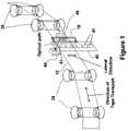
- FIG. 1illustrates an exemplary servo system including an optical servo system configured to sense the edge of a storage medium
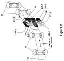
- FIG. 2illustrates another exemplary servo system including an optical servo system configured to sense the edge of a storage medium
- FIG. 3illustrates an exemplary feedback loop for a servo system
- FIGS. 4A , 4 B, and 4 Cillustrate various views of another exemplary servo system including an optical servo system configured to sense the edge of a storage medium;
- FIG. 5illustrates another exemplary servo system including an optical servo system configured to sense the edge of a storage medium
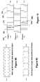
- FIG. 6illustrates an exemplary mask pattern for use in an optical servo system
- FIG. 7illustrates an exemplary signal detected from an optical servo system
- FIG. 8illustrates an exemplary magnetic head assembly relative to a magnetic storage medium and corresponding read signals during a servo process
- FIG. 9Aillustrates another exemplary magnetic head assembly relative to a magnetic storage medium and corresponding read signals during a servo process
- FIGS. 9B and 9Cillustrate exemplary read signals generated from adjacent data tracks
- FIG. 10illustrates another exemplary magnetic head assembly relative to a magnetic storage medium and corresponding read signals during a servo process
- FIG. 11illustrates an exemplary magnetic head assembly relative to a magnetic tape and associated signals generated during a servo process
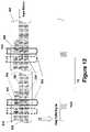
- FIG. 12illustrates another exemplary magnetic head assembly relative to a magnetic tape and associated signals generated during a servo process
- FIG. 13illustrates another exemplary magnetic head assembly relative to a magnetic tape and associated signals generated during a servo process
- FIGS. 14–18illustrate various exemplary magnetic head configurations
- FIG. 19illustrates one channel of an exemplary read-write multi-channel head
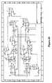
- FIG. 20illustrates an exemplary schematic diagram of circuitry for an optical servo system.
- a closed loop servo systemdeployed by the tape drive electromechanical system, utilizes an estimate of the head's position relative to the storage tape to align the transducer head to a data track position.
- Exemplary methods and systems described belowgather positional information for the positioning of a transducer head relative to data tracks by utilizing existing data structures on a magnetic storage tape and sensing an edge of the storage tape.
- the exemplary methods and systemsmay be used without servo data or separate servo systems including, e.g., mechanical structures to mount an optical system or the like for detecting servo positioning information. With reduced mechanical structure, there may be an increase in servo actuator response, enabling higher actuator band width and finer track width resolution.
- a drive systemmay advantageously write to and read from various format storage cartridges and data formats.
- Super Digital Linear Tape (“Super DLT” or “SDLT”) drives, and Linear Tape Open (“LTO”) drivesmay utilize exemplary servo systems that are compatible with both magnetic servo of LTO and optical servo of Super DLT.
- a servo systemdetects at least one previously written data track (referred to herein as a “reference track”) to provide positional information for a read/write head relative to a presently accessed track (referred to herein as an “active track”).
- an optical servo systemdetects at least one edge of the tape to provide relative positional information for the read/write head.
- the exemplary methods and systemsmay assist various additional servo system(s) or subsystem(s) of a tape drive to align the read/write head with data tracks during reading or writing processes.
- Exemplary tape drive systems and methodsthat may be used with the various exemplary systems and methods of the present invention are described, for example, in U.S. Pat. Nos. 6,246,535, 6,108,159, and 5,371,638, and U.S. patent application Ser. No. 09/865,215, all of which are hereby incorporated by reference as if fully set forth herein. It will be recognized by those of ordinary skill in the art that various other suitable tape drive and servo systems may be used with one or more of the exemplary systems and methods of the present invention.
- magnetic servo information associated with the relative position of a previously written data structuree.g., a previously written data track
- optical servo information associated with the relative position of an edge of the magnetic storage mediume.g., 0.5 inch storage tape
- the relative position of the read/write head with respect to a location of the track being accessed for writing or reading datacan be accurately estimated based on the relative position of the head with respect to the edge of the storage tape and the relative position of a previously written data track (a reference track).
- the servo systemmay use the positional information to adjust the relative position of the magnetic read/write head and the tape.
- the servo systemuses an optical servo method as a primary servo system and magnetic servo of an existing data structure to fine-position the read/write head.
- the following descriptiondetails exemplary optical servo methods and exemplary magnetic read servo methods.
- the relative position of a read/write head with respect to data track locationscan be accurately estimated if the relative position of the read/write head with respect to the edge of the storage medium or tape is known.
- the relative position of the edgemay be sensed relative to the head element with a suitable optical system.
- FIG. 1illustrates one exemplary optical servo system for sensing the relative position of an edge of a storage tape 10 .
- the optical servo systemincludes a light source 46 , stationary optical sensing device 44 , and a patterned mask 40 configured to sense the edge of storage tape 10 .
- Storage tape 10is guided by rollers 38 from a supply reel (e.g., within a cartridge), to a take-up reel (e.g., within a tape drive system) and adjacent read/write head 16 and the optical servo system (generally including light source 46 , sensing device 44 , mask 40 , and a suitable servo controller).
- sensing device 44includes an area or linear detector aligned along the lateral direction. Sensing device 44 detects light through a window blocked by the optical image of the edge of storage tape 10 on one side and an optically coded mask 40 attached or in a fixed spatial relationship to the read/write head 16 on the other side.
- Mask 40includes at least one area of varying transparency to light from light source 46 , e.g., aperture 41 , and mask 40 is coupled or in a fixed spatial relationship to head 16 .
- tape 10will at least partially obstruct the at least one aperture 41 to create at least one window defined by the area of aperture 41 less the area of tape 10 which overlaps aperture 41 along the optical path between light source 46 and sensing device 44 .
- the lateral length of the apertureis set less than the width of tape 100 .
- Light source 46illuminates, e.g., with incoherent light, the at least one window formed by tape 10 and aperture 41 .
- Sensing device 44detects light passing through the window and provides a measure of the relative position of the edge of tape 10 to the head 16 .
- a controllermay adjust the position of head 16 in response to signals from sensing device 44 associated with the detected light. For example, the controller may adjust the position of head 16 to maintain the intensity of the detected light at a particular value, thereby keeping the window at the same or similar size.
- sensing device 44includes a transmissive optical sensor.
- Transmissive optical sensorsare well established and characterized devices in the industry. They are also relatively inexpensive and readily available, however, various suitable sensors may be used, e.g., CCD or CMOS devices. Changes to the read/write head and tape path assembly in existing drive systems, such as the SDLT drive, are generally minor and inexpensive and will be easily recognized by those of ordinary skill in the art.
- an optical servo system including a transmissive optical sensing device similar to that shown in FIG. 1was attached to an SDLT220 drive, manufactured by Quantum Corporation.
- the sensing devicewas positioned such that it monitored the position of the top edge of the tape relative to the position of the read/write head.
- the gain and offset of the accompanying electronic circuitrywere set so that an analog signal was generated with a range of 0 to 3 volts that corresponded to approximately five 24-micron wide SDLT220 format data tracks.
- the analog signalwas used as an input to an A/D converter on the SDLT220 tape drive.
- Each 0.6 volt change in signal(44 out of 256 A/D bits) represented approximately 24 microns.
- FIG. 20is an exemplary schematic diagram of the circuitry used to maintain constant LED light level and to condition the signal for the input to the A/D converter; of course, other designs may be implemented to achieve similar results.
- the drivewas loaded and calibrated with a conventional SDLT220 tape and several data tracks were written in conventional SDLT220 servo mode, i.e., using the optical tracking servo in the drive. The data tracks were then read back by the drive using the optical tracking servo. As the drive was reading, a command sequence was sent to the drive via a diagnostic communication port that switched the drive from using the conventional optical tracking servo to a tape edge servo system (substantially as shown and described in FIG. 1 ). The drive continued reading the data track within reasonable data error rates using the tape edge servo system. Additionally, the drive was able to alternate between standard optical tracking servo and the tape edge servo system while continuing to read the data.
- the drivewas loaded and calibrated with a conventional SDLT220 tape, where the beginning of each forward data track was written using the conventional SDLT220 optical tracking servo. Part way along the track, a command sequence was sent to the drive via a diagnostic communication port that switched the drive from optical tracking servo to the tape edge servo, and the remainder of the track was written using the tape edge servo. The data tracks were read back using the optical tracking servo for the beginning of each track. Part way through each forward track, a command sequence was sent to the drive via a diagnostic communication port which switched the drive from using the conventional optical tracking servo to the tape edge servo. The drive was able to continue reading the tracks within reasonable data error rates.
- an optical sensor and an optically encoded mask attached to the read/write headare provided.
- the mask(or masks) includes at least two apertures or transparent portions.
- the tape, bounded by a first edgemay partially obstruct a first aperture to create a first window
- the tape, bounded by a second edge opposite the first edgemay partially obstruct a second aperture to create a second window. In this manner, if lateral tape motion enlarges the first window, it reduces the second window.
- a sensing devicemay include a first detector for detecting light from the first window, and a second detector for detecting light from the second window.
- the controlleris provided with information concerning relative position of the tape to the read/write head and the direction of motion of the tape with respect to the mask.
- a light sourcemay include a first light source for illuminating the first aperture, and a second light source for illuminating the second aperture.
- the controllermay control the first and second light sources to compensate for ambient effects on the determination of the relative position of the tape to the head, such as ambient light and temperature.
- the servo systemmay also include a third aperture in a mask disposed in the lateral direction, and third and fourth detectors.
- the third detectordetects light through the third aperture obstructed by the tape bounded by the first tape edge
- the fourth detectordetects light through the fourth aperture obstructed by the tape bounded by the second tape edge.
- the total light measured by the third and fourth detectorswill be substantially constant, assuming no ambient effects, if the tape width is constant. Thus, any change in the total light represents a variation in the tape width due to tape edge irregularities, for example.
- the controllermay compensate for tape edge irregularities.
- FIG. 2illustrates an exemplary system having one or more masks with first, second, and third apertures.
- optical paths of four optical sensing devices or sensors 244 - 1 , 244 - 2 , 244 - 3 , and 244 - 4are at least partially blocked from light sources 246 - 1 and 246 - 2 by images of the opposing edges of tape 10 ; two sensors 244 - 1 , 244 - 3 aligned with the top edge and two sensors aligned with the bottom edge 244 - 2 , 244 - 4 .
- An optically coded mask 240is attached or fixed in place relative to read/write head 16 .
- Sensors 244 - 1 , 244 - 2 , 244 - 3 , 244 - 4provide four signals, two of which (sensors 244 - 1 , 244 - 2 ) are proportional to the relative position of the head with respect to the edge of the tape 10 .
- the vertical portion of mask 40 corresponding to sensors 244 - 1 , 244 - 2includes a column of apertures 241 , where each aperture 241 may be shorter in the lateral direction than the width of tape 10 .
- sensors 244 - 3 , 244 - 4may provide signals proportional to the lateral motion of the tape as registered by the tape edge motion.
- the vertical mask portion corresponding to sensors 244 - 3 and 244 - 4includes a long vertical aperture 242 that may be longer in the lateral direction than the width of tape 10 and transparent throughout the expected range of LTM. In other example, two or more masks may be used in place of a single mask 240 .
- K nnrepresent the gain coefficient for each sensor, which depends on the light source intensity and dimensions of the mask apertures 241 , 242 .
- the output value of the sensorsalso varies as a function of ambient temperature and light intensity. This dependence on the ambient temperature and light should be minimized in order to achieve accurate scaling for the output of the sensors.
- the mean value of the LTMshould remain constant (because the tape is kept stationary with respect to the sensor location) such that the average values of b 3 and b 4 will remain substantially constant in the absence of ambient temperature and light variation. Therefore, two feedback control loops, e.g., as illustrated in FIG. 3 , which would modify the intensity of the light source and keep the average values of b 3 and b 4 to a nominal value (K 12 *LTM(nominal); K 22 *LTM(nominal)), are sufficient to minimize the sensitivity of K 12 and K 22 in the above equations to ambient temperature and light.
- Light source 246 - 1illuminates both sensors 244 - 1 and 244 - 3 .
- Light source 246 - 2illuminates both sensor 244 - 2 and 244 - 4 .
- the exemplary methodwill also minimize the sensitivity of K 11 and K 21 to these variations.
- the value of Ks in the linear region of the sensorcan be determined by the calibration techniques initiated by the servo subsystem.
- the sensor signals b 1 , b 2 , b 3 , and b 4individually, will not accurately register the relative head position with respect to the storage tape or data tracks.
- One exemplary method of improving the accuracy of the positioning signal, in the presence of tape edge damageis to determine the common and differential components of these signals as a means to distinguish between tape motion, e.g., LTM, and tape edge irregularities from tape edge damage and the like.
- Td 1 and Td 2represent the upper and lower tape edge irregularities respectively
- b 4Kr *(1 ⁇ LTM+Td 2)
- the Td signalcan be monitored in order to apply a filter (such as a low pass filter) to the signal Pr, thus reducing the sensitivity of Pr to Td.
- a filtersuch as a low pass filter
- the filtercould decrease its cutoff frequency in response to increasing Td, thereby reducing the sensitivity of the filtered Pr to the most recent values of Pr that are contaminated by Td.
- FIGS. 4A , 4 B, and 4 Cillustrate an exemplary optical servo system including two stationary transmissive optical sensors 444 - 1 , 444 - 3 and two optically encoded transparent masks 440 - 1 , 440 - 2 provided to determine positional information.
- One mask 440 - 1is coupled to the read/write head and a second mask 440 - 2 is attached or stationary with respect to the optical sensors 444 - 1 , 444 - 3 .
- the optical sensors 444 - 1 , 444 - 3may be located side-by-side in the longitudinal direction or direction of tape transport.
- the stationary mask 440 - 2includes two side-by-side sections (see FIG. 4B ), which may be (at least in part) spatially complementary to each other.
- Stationary mask 440 - 2may comprise rows, each row corresponding to a data track on a recording tape, which at least partially obstructs light to the optical sensing elements.
- each stationary mask sectionmay comprise a checkerboard pattern of alternating shapes, such as squares or rectangles.
- the moving mask 440 - 1 attached or in a fixed relationship relative to head 16may include a pattern, such as a checkerboard pattern, corresponding to the pattern on one section of stationary mask 440 - 2 .
- the moving mask 440 - 1may have a width in the longitudinal direction that is greater than or equal to the width of the stationary mask 440 - 1 .
- the moving mask 440 - 1overlays the stationary mask 440 - 2 between light source 46 and sensors 440 - 1 , 440 - 2 .
- the overlay of a moving mask 440 - 1 row over a stationary mask 440 - 2 rowis detected by the optical sensors 444 - 1 , 444 - 3 .
- Each row crossingmay correspond to a data track crossing, thereby providing an indication of lateral position of head 16 to sensors 444 - 1 , 444 - 3 .
- the lightis obstructed to sensors 444 - 1 , 444 - 3 .
- the total light reaching the sensors 444 - 1 , 444 - 3 through the masks 440 - 1 , 440 - 2corresponds to lateral tape motion, i.e., the total overlay of the tape 100 over the sensors 444 - 1 , 444 - 3 .
- a controller(not shown) of this example determines relative position of head 16 to tape 100 , allowing control of the position of head 16 with respect to tape 100 .
- the correspondence of the mask rows to data tracksprovides fine measurement and control of the relative position of head 16 to the data tracks.
- the optical paths between light source 46 and two stationary transmissive optical sensing devices 444 - 1 , 444 - 3are blocked by the image of the edge of tape 100 , and two pattern encoded mask bars 440 - 1 and 440 - 2 , one attached to the moving read/write head 16 and the other stationary with respect to the optical sensing devices.
- Sensing devices 444 - 1 , 444 - 3provide two position signals as the read/write head 16 moves laterally with respect to tape 100 .
- the two position signalsare complementary to each other (e.g., 180 degrees out of phase) and quantized in nature to provide direction and magnitude of an offset.
- FIGS. 4B and 4Cillustrate patterns included with both masks 440 - 1 and 440 - 2 in greater detail over varying offset positions.
- the stationary mask 440 - 2has two sections (a, b) positioned side-by-side along the direction of tape transport, each section having a checkerboard pattern with black (optical blocking) and white (optical transparent) blocks, sections a and b.
- Each section a, bis the mirror image of the other section about the y-axis.
- the size of the square or rectangular block of the checkerboard patterncan be associated with data track widths, e.g., a subdivision or multiple of the data track width.
- shapes other than squaresmay be employed such as rectangles, triangles, circles, and the like.
- the dimensions of the squaresare chosen to be 0.5 data track widths.
- Each section of the stationary mask 440 - 2blocks, at least partially, the optical path of one of the two sensors 444 - 1 , 444 - 3 (shown as circles in FIG. 4C ).
- the moving mask 440 - 1may have a homogeneous checkerboard pattern with the same square block dimensions as the stationary mask.
- mask 440 - 1is wider than mask 440 - 2 and head 16 , but in other examples mask 440 - 1 may have various sizes including equal to or smaller than mask 440 - 2 in the lateral direction.
- FIG. 4Cillustrates several alignments (shown as i, ii, iii, and iv) of masks 440 - 1 , 440 - 2 and the edge of tape 100 as head 16 (not shown in FIG. 4C ) and mask 440 - 1 move across the width of tape 100 .
- each optical sensing elementgoes through a cycle of being semi-blocked by the two masks 440 - 1 , 440 - 2 and tape 100 as the black and transparent squares line up to respective black and transparent squares, to being completely blocked as the black and the transparent squares of the moving mask 440 - 2 line up to respective transparent and black squares of the stationary mask 440 - 1 .
- the stationary mask 440 - 2 sectionsare complementary, one sensor experiences minimum light transmission while the other sensor experiences maximum light transmission. Since the optical path for both sensors experiences cycles of maximum light transmission to minimum light transmission for each track length's motion of the head, the resulting positioning signals generally have a wider dynamic range (and better signal-to-noise, ratio) than previous servo systems. With proper signal processing, as will be apparent to those of ordinary skill in the art, the system provides a null position signal for each row of squares shown in FIG. 4C .
- signals b 1 and b 3represent the outputs of sensors 444 - 1 and 444 - 3 , respectively, signal b 1 ⁇ b 3 represents a signal proportional to the position of the read/write head 16 , and signal b 1 +b 3 represents a signal proportional to the position of tape 100 (i.e., related to LTM).
- a servo controllermay use the sum and difference signals to determine and control the position of the read/write head 16 relative to the edge of tape 100 .
- an optical servo systemilluminates an edge of a storage tape and creates a diffraction pattern.
- the diffraction patternis imaged onto a suitable mask and the output of the mask is detected and used to determine the position of the edge of the storage tape.
- FIG. 5illustrates an exemplary optical servo system wherein an optical source 546 illuminates an edge of a storage tape 100 to create a diffraction pattern to provide servo information. Operation of the exemplary servo system may be described by following the light path from left to right in FIG. 5 .
- Light source 546e.g., a laser, provides illumination that diffracts over tape edge 100 , creating a diffraction pattern, which is imaged onto and passes through mask 540 creating an output mask diffraction pattern.
- the output diffraction patternis detected by sensor 544 and may be processed to provide relative positional information of tape 100 within the system.
- light source 546includes a coherent light source, e.g., a laser diode or the like.
- Sensor 544may include any suitable optical sensor array or line scanner such as a CCD or CMOS device.
- Light source 546 , sensor 544 , and mask 540may be mechanically fixed in a known physical relationship relative to tape 100 and a head actuator (not shown).
- mask pattern 540includes four bands of holes, one of which is illustrated in FIG. 6 .
- the maskincludes a hole or transmissive pattern having a pitch of 24 ⁇ m and a diameter of 12 ⁇ m.
- another mask pattern that may be usedincludes lines in the longitudinal direction with suitable spacing and dimensions to provide direction and relative motion information.
- the pattern on mask 540may be one dimensional, comprising elements such as lines with suitable width and spacing, or a grating line pattern for increased light transmission.
- a maskmay include a pattern of varying transmissive materials to the light source.
- two of the orders (0, 0) and (0, ⁇ 1)provide light levels that are out of phase with each other as a function of tape 100 or mask 540 lateral motion.
- the geometry of the systeme.g., the distance from the edge of tape 100 to mask 540 , and the distance from mask 540 to detector 544 , may be adjusted to provide varying amounts of phase difference between the two orders (0, 0) and (0, ⁇ 1).
- the phase difference of the servo systemis 90 degrees out of phase, e.g., as is the case with sine and cosine waveforms.
- FIG. 7illustrates scope traces displaying two orders in one example.
- This maximum intensity track crossingoccurs when the tape edge diffraction pattern is matched over the mask pattern. This signal is the reference point from which tracks can be determined. In the exemplary scope trace shown in FIG. 7 , the maximum intensity track occurs on track 17 .
- exemplary magnetic servo methods and systemsthat may be used in conjunction with optical servo methods and systems using the tape edge will now be described.
- methods and systemsare provided for sensing existing data structures on a magnetic storage tape to determine position information of the transducer head, e.g., using read signals from a reference data track.
- a first data trackis written to a magnetic storage medium based on the ability of the drive system to maintain track position, e.g., through “open loop” control or other servo control methods, e.g., optical servo systems, available to the drive system.
- Subsequent data tracksare referenced from one or more existing or previously written data tracks (referred to herein as a “reference” data track).
- the first data track, nbecomes a reference track for the next adjacent track, n+1.
- a sensore.g., a read element
- Signals that can be used to determine the tracking informationinclude, e.g., track average amplitude, average energy of the reference track, average energy of the read gate (or “rdgate”) signal, PLL-locked/unlocked, transition from readable to unreadable data, k-bit, error rate information, signal noise, and other suitable read/write parametrics that change as a function of track offset as discussed above.
- At least one data track n ⁇ 1is written to storage medium 100 and aligned on storage medium 100 based on the ability of the servo system of the drive.
- the position of a subsequently written data track nis referenced, at least in part, by positioning one or more servo read elements 120 in a known relationship to the previously written data track n ⁇ 1, e.g., aligned near a far edge of the adjacent data track n ⁇ 1.
- Write element 105 and data read element 110are adjusted or moved based on signals from servo read element 120 to reduce variations in the relative position of write element 105 and track n relative to track n ⁇ 1.
- Other servo systems available to the drive systemmay also be used in parallel or serial fashion to provide positional information.
- track n ⁇ 1can be successfully read by servo read element 120 (e.g., within desired error rates, etc.), then track n is correctly positioned with respect to track n ⁇ 1, i.e., track n is not overwriting track n ⁇ 1. If track n ⁇ 1 cannot be successfully read, then the head 110 is repositioned to move track n away from track n ⁇ 1. When track n ⁇ 1 is successfully read, write element 105 may be moved slightly closer to track n ⁇ 1 to reduce spacing between track n and track n ⁇ 1, which may be followed by another read to ensure that track n ⁇ 1 is not being written over.
- the process of reading track n ⁇ 1 with servo read element 120 and making adjustments of write element 105may be performed continuously or intermittently, attempting to keep track n and n ⁇ 1 to a desired width and spacing.
- the pitch of data tracksis in the range of approximately 1 ⁇ m and 44 ⁇ m. Track widths may vary depending on the particular application, desired storage density, error rates, and the like.
- a read elementis aligned with adjacent edges of two reference data tracks to obtain positional information.
- a write elementmay be adjusted based on signals from the read head corresponding to gap phases of the two reference data tracks.
- positional informationmay be acquired by monitoring the amplitude during the gap phase of two adjacent reference tracks and comparing the amplitude to the amplitude of random data.
- an active data track nis written with reference to previously written data tracks n ⁇ 1 and n ⁇ 2.
- servo read element 220straddles the border between the previous data tracks n ⁇ 1 and n ⁇ 2.
- the amplitude of the read signal from track n ⁇ 1 taken during gaps 160 between data blocks 170may be used to determine the relative position of track n compared to tracks n ⁇ 1 and n ⁇ 2.
- FIG. 9Billustrates a nominal read signal envelope of the signal from servo read element 220 .
- the read signalis at maximum amplitude.
- the servo read element 210is positioned over a gap 160 from either track n ⁇ 1 or n ⁇ 2, the read signal will be at half maximum amplitude because half of read element 210 is positioned over a gap 160 .
- FIG. 9Cillustrates the servo read signal when servo read element 210 is positioned off-track.
- the servo read signal envelopecontains alternating gap modulation depths because the amplitude is reduced by more than half of the maximum by gaps 160 associated with one of the tracks and by less than half of the maximum by gaps 160 associated with the other track.
- Write element 205may be adjusted such that the gap modulation depth from the read signal is consistent and equal for each encountered gap 160 .
- the amplitude of the signalsmay be monitored intermittently or continuously to provide information to a servo system to keep the head in a desired position with respect to track n ⁇ 1.
- FIG. 10illustrates another exemplary method, where two servo read elements 320 a and 320 b are aligned with and straddle adjacent edges of two reference data tracks n ⁇ 1 and n ⁇ 2.
- Write element 305may be adjusted based on read signals from the two servo read elements 320 a and 320 b .
- the amplitude of read signals from servo read element 320 a and 320 b during gaps 160indicates a magnitude and direction of the offset.
- the relative amplitudes of the signals from read heads 320 a and 320 b from gaps 160 in track n ⁇ 1 and track n ⁇ 2are compared. If the ratio of the signal amplitudes is 1, then the position of the active track n, is positioned correct.
- the headis repositioned in the appropriate direction. For example, greater amplitude for one read head indicates the direction of offset.
- the read signalsmay be sampled or measured continuously or intermittently, and used by the controller to position the write head in a desired position with respect to tracks n ⁇ 1 and n ⁇ 2.
- a systemmay include a first servo read element configured to read a reference data track and a second servo read element configured to straddle two adjacent reference tracks thereby providing a first signal that varies as a function of track offset and a second signal that detects gap amplitudes indicating track offset.
- a read/write headhalts a read/write process at a predetermined time and the head assembly is moved to locate an edge of a reference data track.
- the systemmay then register the location and boundaries (e.g., edges) of the reference data track relative to the active track and make adjustments to the position of the active track based on predetermined values or signals from the read head.
- the process of halting and checking the location of a reference data trackmay be periodically repeated as desired during writing a data track. For use in a magnetic tape drive, this example can be implemented to obtain accurate and repeatable positioning information.
- a drive servo systemcan read a previously written reference data track 420 and obtain information to fine adjust the position of head 402 over active track 410 (i.e., the track being accessed for either writing or reading data).
- the systemuses data integrity read signals such as Read Channel Data Validity Resources of the tape drive and signal quality metrics of read element 406 when positioned over reference track 420 .
- a read signal quality metricmay be monitored as head 402 including reference head 406 pass over reference track 420 .
- the relative layout of the central position and/or edges of reference track 420 with respect to the location of the active track 410may assist the drive servo system to adjust the position of head 402 over track 410 .
- the Read Channel Data Validity Resources(“RCDVR”) provide a relay type signal (ON/OFF), referred to as a “Data Valid” signal ( FIG. 11 “Data Valid Signal”), representative of the ability of the read element 406 to recover data based on any, or combination of any, of the following data validity indicators and signals:
- FIG. 11illustrates an exemplary read signal received from head 402 that may determine the relative position of head 402 during operation.
- the data valid signalchanges its state from “OFF” near the edge of reference track 420 where data is not valid to “ON” where the data become valid and back to OFF where the read element crosses the opposite edge of reference track 420 .
- the servo systemmay halt the read/write function over the active track 410 at specified time period (Track Layout Check period: Ts as shown in FIG. 11 ) and initiate a seek to and over the edges of reference track 420 .
- the servo systemBy monitoring the state of the data valid signal and instantaneous relative position of head 402 with respect to the active track 410 location provided by the servo position-sensing device, the servo system registers the location and boundaries of reference track 420 relative to active track 410 . This registered value referred to as “Reference Position” is compared to a nominal value. If there is no difference then track layout is correct and the servo system may initiate another seek back to active track 410 to resume read/write functions with no further action until the next Track Layout Check time Ts.
- the servo systemwill initiate another seek back to active track 410 and modify the reference position of the servo positioning loop to correct the track layout back to the nominal dimensions. The system then resumes read/write functions until the next Track Layout Check time Ts.
- the read/write processis halted and a dedicated read element is moved to locate an edge of a reference data track during a read/write process of an active track.
- the systemmay register the location and boundaries of the reference data track relative to the active track and make adjustments to the position of the active track based on predetermined values or signals from the read element as described above.
- the process of halting and checking the location of a reference data trackmay be periodically repeated as desired during writing a data track.
- FIG. 12is similar to the example of FIG. 11 except that a dedicated servo read element 508 is included with head assembly 502 .
- Servo read elementis positioned adjacent an edge of reference track 520 and therefore requires less movement of head 502 and time to reference one or more edges and/or the center position of reference track 520 .
- the method and systemuses RCDVR signals from dedicated servo read element 508 to determine the location of the active read element 506 and write element 504 with respect to the edge of reference track 520 . The positional information is then used to assist the servo system to adjust the read element 506 and write element 504 over active track 510 .
- a dedicated read headprovides a continuous read signal associated with the relative position of a reference data track with the location of the active track.
- the servo systemmay use the position information to adjust the position of the write head to a desired relative position with the reference data track.
- FIG. 13is similar to the example of FIG. 12 except that dedicated servo read element 608 provides a continuous signal associated with the position of servo read element 608 relative to reference track 620 . Accordingly, in this example, the servo system may make continuous position determinations and continuous adjustments to the position of head 602 .
- the read signal(or data valid signal) provides a linear signal proportional to the relative position of servo read element 608 to the edge of reference track 620 .
- the read signalis used as a feed back positioning signal to enforce the tracking of the edge of reference track 620 by the servo read element 608 .
- the design of head 602is such that, when servo read element 608 tracks the edge of reference track 620 the active read element 606 and write element 604 are positioned over active track 610 . Accordingly, the exemplary method supplies the servo system with a servo read signal for positioning head 602 over desired track positions, laid out alongside and parallel to a previously written or reference track.
- firmwarewas written for a SDLT220 tape drive manufactured by Quantum Corporation.
- the firmwareutilized the optical tracking servo system of the SDLT220 with “assistance” from reading the edge of an adjacent reference track.
- a Read Gate signalis generated by the SDLT220 read channel that indicates whether the read channel has read a good block of data. If the Read Gate signal is greater than a predetermined value, then the data block was good. Conversely, if the Read Gate signal is below the predetermined value, then the data block was bad.
- One exemplary head designincludes a center tapped head having two read elements where one read element includes a dedicated read element positioned to derive servo positioning information from an adjacent data track. For example, a first read element reads data on the currently active desired track while a second read head provides servo position information from the adjacent reference data track.
- FIG. 14illustrates an exemplary center tapped head 1400 with two effective read elements 32 and 36 .
- read element 32is configured to be positioned on the center of an active track and is approximately 0.50 track widths.
- Read element 36is approximately 0.8 track widths and separated 0.60 track widths away from read element 32 by recess 34 .
- Read element 36is configured to be positioned on the reference track center.
- the dimensions of the second read element 36in this example 0.8 track widths, are at the limits of track qualifiers, which are used for fine track positioning.
- the portion of head 1400 including read elements 32 and 36includes one magneto-resistive strip.
- the electrical connections of head 1400are such that the data read element lead 20 , and the servo read element lead 24 , are independent from the common lead 22 .
- FIG. 15illustrates an exemplary head 1500 .
- head 1500is center tapped with two read elements 32 and 36 , where read element 32 is 0.5 track widths and positioned at the center of the active track, and read element 36 is also 0.5 track widths and separated 0.25 track widths away from read element 32 by recess 34 .
- read element 36may be aligned with the reference track edge and sense track qualifiers or the like to provide positioning information for the servo system.
- FIG. 16illustrates an exemplary head 1600 .
- head 1600is center tapped with two read elements 32 and 36 .
- the configuration of head 1600is similar to FIG. 15 , except that recess 34 is 0.65 track widths such that read element 36 is configured to be aligned with the opposite edge of a reference track.
- FIG. 17illustrates an exemplary head 1700 with multiple taps and multiple read elements.
- Head 1700includes three read elements 32 , 36 , and 40 separated by recesses 34 and 38 .
- the first read element 32is for reading the active track and is positioned nominally at track center.
- the second read element 36is positioned near a reference track edge, e.g., on the edge of track n ⁇ 1 near edge n ⁇ 2.
- the third read element 40is positioned on a second reference track, e.g., on the edge of track n ⁇ 2 near n ⁇ 1.
- Head 1700may be used is a push-pull configuration with two read elements sensing servo qualifiers from the track edge at the n ⁇ 1 and n ⁇ 2 boundary.
- Head 1700further includes common lead 22 and read element lead 26 .
- FIG. 18illustrates another exemplary head 1800 .
- the data read element 32having a width of 0.5 track widths is positioned 1.5 track widths away from the center of servo read head 36 .
- the separation formed by recess 34 between the read element 32 and read element 36is 1.0 track width.
- the exemplary head 1800may form one magneto-resistive strip of a multi-head channel as described below.
- FIG. 19illustrates the relative geometry of a typical read-write multi-channel head using the center tapped data and servo read element.
- write elements 1905are shown in relation to data read elements 1932 and servo read elements 1936 for one channel.
Landscapes
- Adjustment Of The Magnetic Head Position Track Following On Tapes (AREA)
- Optical Recording Or Reproduction (AREA)
Abstract
Description
b1=K11*(hp−LTM)
b2=K21*(1−hp+LTM)
b3=K12*(1−LTM)
b4=K22*(LTM)
K12*LTM(nominal)=K22*LTM(nominal), whereK12=K22=Kr; K11=K21=Ks
Pr=b2−b1=Ks*(1−2hp+2LTM)
b3=Kr*(LTM+Td1)
b4=Kr*(1−LTM+Td2)
Td=b3+b4=Kr(1+Td1+Td2)
- 1. Data amplitude valid
- 2. Data frequency/Phase valid (phase lock loop valid)
- 3. Data Block's Pre-amble/Post-amble amplitude and or phase/frequency and or sync signal valid
- 4. Data pattern Valid
- 5. Data Block's Pre-amble/Post-amble pattern valid.
Claims (36)
Priority Applications (3)
| Application Number | Priority Date | Filing Date | Title |
|---|---|---|---|
| US10/942,658US7102845B2 (en) | 2003-10-20 | 2004-09-15 | Servo methods and systems using existing data structures and medium edge position |
| EP04256387AEP1538607A1 (en) | 2003-10-20 | 2004-10-18 | Servo methods and systems using existing data structures and medium edge position |
| JP2004304670AJP2005166235A (en) | 2003-10-20 | 2004-10-19 | Transducer head positioning method and head positioning servo system |
Applications Claiming Priority (2)
| Application Number | Priority Date | Filing Date | Title |
|---|---|---|---|
| US51315603P | 2003-10-20 | 2003-10-20 | |
| US10/942,658US7102845B2 (en) | 2003-10-20 | 2004-09-15 | Servo methods and systems using existing data structures and medium edge position |
Publications (2)
| Publication Number | Publication Date |
|---|---|
| US20050083602A1 US20050083602A1 (en) | 2005-04-21 |
| US7102845B2true US7102845B2 (en) | 2006-09-05 |
Family
ID=34468043
Family Applications (1)
| Application Number | Title | Priority Date | Filing Date |
|---|---|---|---|
| US10/942,658Expired - Fee RelatedUS7102845B2 (en) | 2003-10-20 | 2004-09-15 | Servo methods and systems using existing data structures and medium edge position |
Country Status (3)
| Country | Link |
|---|---|
| US (1) | US7102845B2 (en) |
| EP (1) | EP1538607A1 (en) |
| JP (1) | JP2005166235A (en) |
Cited By (8)
| Publication number | Priority date | Publication date | Assignee | Title |
|---|---|---|---|---|
| US20060209450A1 (en)* | 2005-03-18 | 2006-09-21 | Quantum Corporation | Auto-servo tape system and associated recording head |
| US20070064327A1 (en)* | 2004-05-24 | 2007-03-22 | Quantum Corporation | Servo track having periodic frames of tone field and embedded synchronization marks |
| US20070121240A1 (en)* | 2005-11-28 | 2007-05-31 | Duran Carlos A | LTM compensation methods and systems for magnetic servo writing |
| US20080266705A1 (en)* | 2007-04-25 | 2008-10-30 | Quantum Corporation | Servo error detection and compensation utilizing virtual data tracking servo methods |
| US20110013313A1 (en)* | 2009-07-17 | 2011-01-20 | International Business Machines Corporation | Method and apparatus to set a wrap angle of a read/write head |
| US20110102937A1 (en)* | 2009-11-04 | 2011-05-05 | International Business Machines Corporation | Positioning coarse servo actuator of tape servo system to allow fine servo actuator to follow tape shift excursions |
| US20110216440A1 (en)* | 2010-03-02 | 2011-09-08 | International Business Machines Corporation | Positioning a coarse actuator of compound actuator tape servo system at midpoint of maximum peaks of lateral tape movement |
| US8964319B1 (en)* | 2014-03-05 | 2015-02-24 | International Business Machines Corporation | Tape media kiss-contact read verification |
Families Citing this family (10)
| Publication number | Priority date | Publication date | Assignee | Title |
|---|---|---|---|---|
| US7136255B2 (en)* | 2003-10-20 | 2006-11-14 | Quantum Corporation | Servo methods and systems using masked medium edge position sensors |
| US7149050B2 (en)* | 2003-10-20 | 2006-12-12 | Quantum Corporation | Diffractive position sensors and control systems |
| US7139152B2 (en)* | 2003-10-20 | 2006-11-21 | Quantum Corporation | Servo methods and systems using existing data structures and optical masks |
| US7085095B2 (en)* | 2003-10-20 | 2006-08-01 | Quantum Corporation | Electromagnetic void-sensing probes and position control systems |
| US7116514B2 (en)* | 2003-10-20 | 2006-10-03 | Quantum Corporation | Methods and systems for magnetic recording |
| US7184233B2 (en)* | 2004-06-04 | 2007-02-27 | Quantum Corporation | Dual source tracking servo systems and associated methods |
| US8514675B2 (en) | 2011-05-11 | 2013-08-20 | Oracle International Corporation | Suspension system for an optical pickup assembly |
| GB2502579A (en) | 2012-05-31 | 2013-12-04 | Ibm | Tape head with movable read/write segments each having a further read element, and tape with servo patterns |
| US9336812B1 (en) | 2015-01-09 | 2016-05-10 | Oracle International Corporation | Adaptive control of tracking servo system of optical heads in optical storage devices |
| US9911458B1 (en)* | 2016-08-30 | 2018-03-06 | Oracle International Corporation | Apparatus for minimizing cross track interference for optical tape |
Citations (101)
| Publication number | Priority date | Publication date | Assignee | Title |
|---|---|---|---|---|
| US2937239A (en) | 1956-02-13 | 1960-05-17 | Gen Electric | Skew servo for multiple channel recording system |
| US3633038A (en)* | 1970-05-01 | 1972-01-04 | Newell Ind | Transducer-positioning system using radiation-sensitive means |
| US3829895A (en) | 1970-08-17 | 1974-08-13 | Matsushita Electric Industrial Co Ltd | Multi-channel magnetic head with offset gap lines |
| US3919697A (en) | 1974-06-26 | 1975-11-11 | Battelle Development Corp | Data record tracking using track identifying information in the gaps between recorded data groups |
| US3971002A (en) | 1973-06-29 | 1976-07-20 | Thomson-Brandt | Device for the optical read-out of a diffractive track belonging to a data carrier in the form of a disc or tape |
| US4056830A (en) | 1974-03-15 | 1977-11-01 | Burroughs Corporation | Utilizing data for transducer positioning |
| US4110799A (en) | 1976-01-17 | 1978-08-29 | U.S. Philips Corporation | Servo system for controlling the position of a magnetic head relative to a track to be followed using periodically interrupted long-wave positioning signals |
| US4149204A (en) | 1977-03-28 | 1979-04-10 | International Business Machines Corporation | Minor bit reduction on a magnetic head |
| US4176381A (en) | 1977-11-11 | 1979-11-27 | U.S. Philips Corporation | Recording and/or reproducing apparatus for a magnetic record carrier in the form of a tape, provided with a control system for the magnetic head position |
| US4321634A (en) | 1977-10-07 | 1982-03-23 | Thomson-Csf | Endless magnetic tape video recorder/player with head centering means |
| US4334252A (en) | 1979-03-20 | 1982-06-08 | Mitsubishi Denki Kabushiki Kaisha | Magnetic recording and reproducing head arrangement |
| US4392163A (en) | 1979-09-28 | 1983-07-05 | U.S. Philips Corporation | Magnetic tape recording and/or reproducing apparatus with automatic head positioning |
| US4422112A (en) | 1980-06-13 | 1983-12-20 | Tokyo Shibaura Denki Kabushiki Kaisha | Magnetic recording and reproducing apparatus |
| US4424541A (en) | 1980-02-29 | 1984-01-03 | Victor Company Of Japan, Limited | Apparatus and method for multi-track recording of a digital signal |
| US4439793A (en) | 1981-10-22 | 1984-03-27 | Fuji Photo Film Co., Ltd. | Thin film head array |
| US4449082A (en) | 1981-12-17 | 1984-05-15 | Webster Douglas G | Motor speed control system |
| US4472750A (en) | 1981-07-02 | 1984-09-18 | Irwin Magnetic Systems, Inc. | Data record with pre-recorded transducer positioning signals, and system for utilizing same |
| JPS59185020A (en) | 1982-12-10 | 1984-10-20 | Sony Corp | Tape recorder |
| US4479156A (en) | 1981-05-11 | 1984-10-23 | Mitsubishi Denki Kabushiki Kaisha | Magnetic disk recorder |
| US4502082A (en) | 1977-06-16 | 1985-02-26 | Burroughs Corporation | Spiral recording and associated system |
| US4539615A (en) | 1981-06-08 | 1985-09-03 | Hitachi, Ltd. | Azimuthal magnetic recording and reproducing apparatus |
| US4679104A (en) | 1985-02-08 | 1987-07-07 | Tandberg Data A/S | Method and arrangement for positioning a magnetic head to various tracks of a magnetic tape |
| US4685005A (en) | 1983-07-18 | 1987-08-04 | International Business Machines Corporation | Two-module-read, read-after-write, bi-directional tape drive |
| US4802030A (en) | 1986-06-25 | 1989-01-31 | Hewlett-Packard Company | Head-tape alignment apparatus with a tape edge find operation |
| US4816939A (en)* | 1986-08-21 | 1989-03-28 | Polaroid Corporation | Magnetic recording media and servo systems using light-transmitting optical gratings |
| US4866548A (en) | 1986-12-22 | 1989-09-12 | Tandberg Data A/S | Method and arrangement for precise positioning of a magnetic head to various tracks of a magnetic tape |
| US4975791A (en) | 1988-03-22 | 1990-12-04 | Carlisle Memory Products Group Incorporated | Recording system having head transducers with controlled skew |
| US4979051A (en) | 1988-03-22 | 1990-12-18 | Eggebeen James A | Bimodal multi-track magnetic head |
| US5050017A (en) | 1989-08-23 | 1991-09-17 | Eastman Kodak Company | Memory guided magnetic tape tracking |
| US5055959A (en) | 1990-01-09 | 1991-10-08 | Digital Equipment Corporation | Tape head with low spacing loss produced by narrow and wide wear regions |
| US5072319A (en) | 1988-07-11 | 1991-12-10 | Matsushita Electric Industrial Co., Ltd. | Magnetic recording/or reproducing apparatus |
| US5121270A (en) | 1989-09-19 | 1992-06-09 | Alcudia Ezra R | Multitransducer head positioning servo for use in a bi-directional magnetic tape system |
| US5126895A (en) | 1989-05-11 | 1992-06-30 | Teac Corporation | Shockproof data transducer position control system for rotating disk data storage apparatus |
| US5132861A (en) | 1989-10-02 | 1992-07-21 | Behr Michael I | Systems using superimposed, orthogonal buried servo signals |
| US5257148A (en) | 1989-05-30 | 1993-10-26 | Tandberg Data As | Method and apparatus for positioning a magnetic head in a magnetic layer memory system using tracking by reading a spaced pair of corresponding subtracks |
| US5262908A (en) | 1990-02-20 | 1993-11-16 | Sharp Kabushiki Kaisha | Tracking control device for magnetic recording/reproducing apparatus |
| US5285331A (en) | 1989-02-23 | 1994-02-08 | Wangtek Incorporated | System for aligning a read head gap over a track of magnetic data |
| US5289328A (en) | 1992-05-26 | 1994-02-22 | George Saliba | Method and apparatus for variable density read-after-writing on magnetic tape |
| US5294803A (en)* | 1991-12-30 | 1994-03-15 | Tandberg Data A/S | System and a method for optically detecting an edge of a tape |
| US5371638A (en) | 1992-06-24 | 1994-12-06 | Digital Equipment Corporation | Servo method and apparatus for very high track density magnetic recording by adjusting head position based on servo information read from adjacent track |
| US5426551A (en) | 1993-07-19 | 1995-06-20 | Quantum Corp. | Magnetic contact head having a composite wear surface |
| US5448430A (en) | 1993-08-05 | 1995-09-05 | International Business Machines Corporation | Track following servo demodulation |
| US5452152A (en) | 1990-08-28 | 1995-09-19 | Tandberg Data A/S | Tracking control on longitudinal azimuth tracks using an auxiliary read head |
| US5488519A (en) | 1990-04-06 | 1996-01-30 | Sony Corporation | Recording and reproducing device having conductive spindle |
| US5523904A (en) | 1992-06-24 | 1996-06-04 | Quantum Corporation | Linear tape write servo using embedded azimuth servo blocks |
| US5563868A (en) | 1990-06-18 | 1996-10-08 | Matsushita-Kotobuki Electronics Industries, Ltd. | Optical servo system for magnetic disk |
| US5588007A (en) | 1996-04-26 | 1996-12-24 | Iomega Corporation | Method for detecting transient write errors in a disk drive |
| US5600505A (en) | 1994-06-10 | 1997-02-04 | Exabyte Corporation | Skew correction in a multi-track tape recorder/player |
| US5600500A (en) | 1994-11-14 | 1997-02-04 | Seagate Technology, Inc. | Performance based write current optimization process |
| US5617269A (en) | 1991-12-23 | 1997-04-01 | Conner Peripherals, Inc. | System for recording track-centering servo signals on multi-track magnetic medium |
| US5757575A (en) | 1996-10-31 | 1998-05-26 | Ampex Corporation | Track-curvature detection using clock phase shift in azimuth recording |
| EP0854471A1 (en) | 1997-01-21 | 1998-07-22 | Tandberg Data ASA | Tape cartridge with integrated mirror tracking mechanism |
| US5796537A (en) | 1995-11-13 | 1998-08-18 | Seagate Technology, Inc. | Method and arrangement for servoing and formatting magnetic recording tape |
| US5815337A (en) | 1995-10-24 | 1998-09-29 | Seagate Technology, Inc. | Tape drive having an arcuate scanner and a method for calibrating the arcuate scanner |
| US5844814A (en) | 1996-09-27 | 1998-12-01 | International Business Machines Corporation | Optical position sensing device and method for sub-micron measurement |
| US5847892A (en) | 1995-11-13 | 1998-12-08 | Seagate Technology, Inc. | Servoing and formatting magnetic recording tape in an arcuate scanner system |
| US5862014A (en) | 1996-01-11 | 1999-01-19 | Quantum Corporation | Multi-channel magnetic tape head module including flex circuit |
| EP0919990A2 (en) | 1997-11-24 | 1999-06-02 | Hewlett-Packard Company | Backwards read/write capability in linear tape by track trimming |
| US5940238A (en) | 1996-06-07 | 1999-08-17 | Seagate Technology, Inc. | Mechanism to reduce adjacent track interference in a magnetic tape data storage system |
| US5949604A (en) | 1992-06-24 | 1999-09-07 | Quantum Corporation | Method of writing and reading servo on tracks having a longitudinal gap |
| US5973872A (en) | 1997-01-23 | 1999-10-26 | Quantum Corporation | Method and apparatus for a low cost multi-channel tape recording head |
| US5973874A (en) | 1996-01-11 | 1999-10-26 | Quantum Corporation | Four channel azimuth and two channel non-azimuth read-after-write longitudinal magnetic head |
| US5978188A (en) | 1996-06-28 | 1999-11-02 | Deutsche Thomson-Brandt | Multitrack tape device using a movable magnetic head with a planar surface and including a tape supporting device |
| US5982711A (en) | 1997-06-05 | 1999-11-09 | Hewlett-Packard Co. | Device for reading data from or writing data to magnetic storage media and a method of positioning a tape head relative to the magnetic storage media |
| US6005737A (en) | 1997-05-24 | 1999-12-21 | Seagate Technology, Inc. | Magnetic tape drive having improved servo control |
| US6018434A (en) | 1997-01-14 | 2000-01-25 | Quantum Corporation | Tape cartridge having written-in-defect servo patterns for rapid head position calibration |
| EP0996127A2 (en) | 1998-10-10 | 2000-04-26 | Deutsche Thomson-Brandt Gmbh | Method for tracking control |
| US6075678A (en) | 1998-03-24 | 2000-06-13 | Quantum Corporation | Pivoting lever cam guide tape head positioner |
| US6084740A (en) | 1997-12-01 | 2000-07-04 | Storage Technology Corporation | Optical servo system for a tape drive |
| US6088184A (en) | 1998-06-16 | 2000-07-11 | International Business Machines Corporation | Apparatus and method for the control and positioning of magnetic recording heads in an azimuth recording system |
| US6108159A (en) | 1997-07-14 | 2000-08-22 | Quantum Corporation | Data track edge follower servo method and apparatus |
| US6118605A (en) | 1997-11-25 | 2000-09-12 | Storage Technology Corporation | System for gap positioning optimization in a tape drive |
| US6128155A (en) | 1997-12-16 | 2000-10-03 | Mitsubishi Denki Kabushiki Kaisha | High density magnetic recording apparatus including a hologram type magnetic head positioning system |
| US6130792A (en) | 1995-11-13 | 2000-10-10 | Seagate Technology, Inc. | Flat servo bursts for arcuate track scanner |
| US6134072A (en) | 1997-03-26 | 2000-10-17 | Exabyte Corporation | Tracking of non-native stripes in helical scan tape drive |
| US6141174A (en) | 1998-08-14 | 2000-10-31 | Quantum Corporation | Method of reading recorded information from a magnetic tape that compensates for track pitch changes |
| US6188532B1 (en) | 1998-09-08 | 2001-02-13 | Quantum Corporation | Backward compatible head and head positioning assembly for a linear digital tape drive |
| US6222698B1 (en) | 1998-05-22 | 2001-04-24 | Hewlett-Packard Company | Magnetic tape dimensional instability compensation by varying recording head azimuth angle |
| US6246535B1 (en) | 1998-11-13 | 2001-06-12 | Quantum Corporation | Optical apparatus for tracking a magnetic tape |
| US6275350B1 (en) | 1998-04-03 | 2001-08-14 | Hewlett-Packard Company | Magnetic head and method for compensating for magnetic tape dimensional instability |
| US6275349B1 (en) | 1998-12-02 | 2001-08-14 | Storage Technology Corporation | Integrated optical tracking system for magnetic media |
| US6307718B1 (en) | 1995-11-13 | 2001-10-23 | Quantum Corporation | Tape head positioning device for adjusting azimuth head tilt |
| US6339522B1 (en) | 2000-05-11 | 2002-01-15 | Tandberg Data Asa | Magnetic data transfer system with dynamic head-to-tape alignment |
| US6366422B1 (en) | 1999-04-01 | 2002-04-02 | Storage Technology Corporation | Helical scan tape drive error recovery using track profile mapping |
| US6433951B1 (en)* | 1999-02-17 | 2002-08-13 | Imation Corp. | Magnetic data storage tape with etched servo pattern, method of manufacturing same, and method of servo positioning on same |
| US20020176200A1 (en) | 2001-05-24 | 2002-11-28 | Hitesh Trivedi | Magnetic track following servo algorithm using signal quality |
| US6493174B1 (en)* | 2000-02-17 | 2002-12-10 | Imation Corp. | Optical servo system for use with magnetic data storage tape having magnetic reference indicators |
| US6512651B1 (en) | 2000-07-11 | 2003-01-28 | Storage Technology Corporation | Helical scan tape track following |
| US20030043498A1 (en) | 2001-09-05 | 2003-03-06 | Robert Johnson | Magnetic servo of a recording head |
| US6545837B1 (en) | 1999-12-21 | 2003-04-08 | Imation Corp. | Method and apparatus for servo controlled azimuth data recording |
| US6570731B2 (en) | 2001-05-14 | 2003-05-27 | Quantum Corporation | System for detecting an edge of a moving data storage medium |
| US6700729B1 (en) | 2000-10-17 | 2004-03-02 | Hewlett-Packard Development Company | Alignment marks for tape head positioning |
| US20040042115A1 (en) | 2001-06-07 | 2004-03-04 | Saliba George A. | Optical apparatus for tracking a magnetic tape |
| US6768608B2 (en)* | 1998-03-24 | 2004-07-27 | Quantum Corporation | Multi-channel magnetic tape system having optical tracking servo |
| US6775092B2 (en) | 2001-12-07 | 2004-08-10 | Quantum Corporation | Lateral tape motion sensor |
| US6801383B2 (en) | 2002-04-04 | 2004-10-05 | Quantum Corporation | Method for calibrating a tape media using staggered calibration tracks |
| US20050083601A1 (en) | 2003-10-20 | 2005-04-21 | Faramarz Mahnad | Servo methods and systems using existing data structures and optical masks |
| US20050083600A1 (en) | 2003-10-20 | 2005-04-21 | Faramarz Mahnad | Methods and systems for magnetic recording |
| US20050088776A1 (en) | 2003-10-20 | 2005-04-28 | Saliba George A. | Diffractive position sensors and control systems |
| US20050088770A1 (en) | 2003-10-20 | 2005-04-28 | George A. Saliba | Electromagnetic void-sensing probes and position control systems |
| US20050094308A1 (en) | 2003-10-20 | 2005-05-05 | Faramarz Mahnad | Servo methods and systems using masked medium edge position sensors |
Family Cites Families (1)
| Publication number | Priority date | Publication date | Assignee | Title |
|---|---|---|---|---|
| US5940604A (en)* | 1996-11-19 | 1999-08-17 | Unisys Corporation | Method and apparatus for monitoring the performance of a circuit optimization tool |
- 2004
- 2004-09-15USUS10/942,658patent/US7102845B2/ennot_activeExpired - Fee Related
- 2004-10-18EPEP04256387Apatent/EP1538607A1/ennot_activeWithdrawn
- 2004-10-19JPJP2004304670Apatent/JP2005166235A/enactivePending
Patent Citations (111)
| Publication number | Priority date | Publication date | Assignee | Title |
|---|---|---|---|---|
| US2937239A (en) | 1956-02-13 | 1960-05-17 | Gen Electric | Skew servo for multiple channel recording system |
| US3633038A (en)* | 1970-05-01 | 1972-01-04 | Newell Ind | Transducer-positioning system using radiation-sensitive means |
| US3829895A (en) | 1970-08-17 | 1974-08-13 | Matsushita Electric Industrial Co Ltd | Multi-channel magnetic head with offset gap lines |
| US3971002A (en) | 1973-06-29 | 1976-07-20 | Thomson-Brandt | Device for the optical read-out of a diffractive track belonging to a data carrier in the form of a disc or tape |
| US4056830A (en) | 1974-03-15 | 1977-11-01 | Burroughs Corporation | Utilizing data for transducer positioning |
| US3919697A (en) | 1974-06-26 | 1975-11-11 | Battelle Development Corp | Data record tracking using track identifying information in the gaps between recorded data groups |
| US4110799A (en) | 1976-01-17 | 1978-08-29 | U.S. Philips Corporation | Servo system for controlling the position of a magnetic head relative to a track to be followed using periodically interrupted long-wave positioning signals |
| US4149204A (en) | 1977-03-28 | 1979-04-10 | International Business Machines Corporation | Minor bit reduction on a magnetic head |
| US4502082A (en) | 1977-06-16 | 1985-02-26 | Burroughs Corporation | Spiral recording and associated system |
| US4321634A (en) | 1977-10-07 | 1982-03-23 | Thomson-Csf | Endless magnetic tape video recorder/player with head centering means |
| US4176381A (en) | 1977-11-11 | 1979-11-27 | U.S. Philips Corporation | Recording and/or reproducing apparatus for a magnetic record carrier in the form of a tape, provided with a control system for the magnetic head position |
| US4334252A (en) | 1979-03-20 | 1982-06-08 | Mitsubishi Denki Kabushiki Kaisha | Magnetic recording and reproducing head arrangement |
| US4392163A (en) | 1979-09-28 | 1983-07-05 | U.S. Philips Corporation | Magnetic tape recording and/or reproducing apparatus with automatic head positioning |
| US4424541A (en) | 1980-02-29 | 1984-01-03 | Victor Company Of Japan, Limited | Apparatus and method for multi-track recording of a digital signal |
| US4422112A (en) | 1980-06-13 | 1983-12-20 | Tokyo Shibaura Denki Kabushiki Kaisha | Magnetic recording and reproducing apparatus |
| US4479156A (en) | 1981-05-11 | 1984-10-23 | Mitsubishi Denki Kabushiki Kaisha | Magnetic disk recorder |
| US4539615A (en) | 1981-06-08 | 1985-09-03 | Hitachi, Ltd. | Azimuthal magnetic recording and reproducing apparatus |
| US4472750A (en) | 1981-07-02 | 1984-09-18 | Irwin Magnetic Systems, Inc. | Data record with pre-recorded transducer positioning signals, and system for utilizing same |
| US4439793A (en) | 1981-10-22 | 1984-03-27 | Fuji Photo Film Co., Ltd. | Thin film head array |
| US4449082A (en) | 1981-12-17 | 1984-05-15 | Webster Douglas G | Motor speed control system |
| JPS59185020A (en) | 1982-12-10 | 1984-10-20 | Sony Corp | Tape recorder |
| US4685005A (en) | 1983-07-18 | 1987-08-04 | International Business Machines Corporation | Two-module-read, read-after-write, bi-directional tape drive |
| US4679104A (en) | 1985-02-08 | 1987-07-07 | Tandberg Data A/S | Method and arrangement for positioning a magnetic head to various tracks of a magnetic tape |
| US4802030A (en) | 1986-06-25 | 1989-01-31 | Hewlett-Packard Company | Head-tape alignment apparatus with a tape edge find operation |
| US4816939A (en)* | 1986-08-21 | 1989-03-28 | Polaroid Corporation | Magnetic recording media and servo systems using light-transmitting optical gratings |
| US4866548A (en) | 1986-12-22 | 1989-09-12 | Tandberg Data A/S | Method and arrangement for precise positioning of a magnetic head to various tracks of a magnetic tape |
| US4975791A (en) | 1988-03-22 | 1990-12-04 | Carlisle Memory Products Group Incorporated | Recording system having head transducers with controlled skew |
| US4979051A (en) | 1988-03-22 | 1990-12-18 | Eggebeen James A | Bimodal multi-track magnetic head |
| US5072319A (en) | 1988-07-11 | 1991-12-10 | Matsushita Electric Industrial Co., Ltd. | Magnetic recording/or reproducing apparatus |
| US5285331A (en) | 1989-02-23 | 1994-02-08 | Wangtek Incorporated | System for aligning a read head gap over a track of magnetic data |
| US5126895A (en) | 1989-05-11 | 1992-06-30 | Teac Corporation | Shockproof data transducer position control system for rotating disk data storage apparatus |
| US5257148A (en) | 1989-05-30 | 1993-10-26 | Tandberg Data As | Method and apparatus for positioning a magnetic head in a magnetic layer memory system using tracking by reading a spaced pair of corresponding subtracks |
| US5050017A (en) | 1989-08-23 | 1991-09-17 | Eastman Kodak Company | Memory guided magnetic tape tracking |
| US5121270A (en) | 1989-09-19 | 1992-06-09 | Alcudia Ezra R | Multitransducer head positioning servo for use in a bi-directional magnetic tape system |
| US5132861A (en) | 1989-10-02 | 1992-07-21 | Behr Michael I | Systems using superimposed, orthogonal buried servo signals |
| US5055959A (en) | 1990-01-09 | 1991-10-08 | Digital Equipment Corporation | Tape head with low spacing loss produced by narrow and wide wear regions |
| US5262908A (en) | 1990-02-20 | 1993-11-16 | Sharp Kabushiki Kaisha | Tracking control device for magnetic recording/reproducing apparatus |
| US5488519A (en) | 1990-04-06 | 1996-01-30 | Sony Corporation | Recording and reproducing device having conductive spindle |
| US5563868A (en) | 1990-06-18 | 1996-10-08 | Matsushita-Kotobuki Electronics Industries, Ltd. | Optical servo system for magnetic disk |
| US5452152A (en) | 1990-08-28 | 1995-09-19 | Tandberg Data A/S | Tracking control on longitudinal azimuth tracks using an auxiliary read head |
| US5617269A (en) | 1991-12-23 | 1997-04-01 | Conner Peripherals, Inc. | System for recording track-centering servo signals on multi-track magnetic medium |
| US5294791A (en)* | 1991-12-30 | 1994-03-15 | Tandberg Data A/S | System and a method for controlling position of a magnetic head relative to a servo track of a tape by optical detection of an edge of the tape |
| US5294803A (en)* | 1991-12-30 | 1994-03-15 | Tandberg Data A/S | System and a method for optically detecting an edge of a tape |
| US5289328A (en) | 1992-05-26 | 1994-02-22 | George Saliba | Method and apparatus for variable density read-after-writing on magnetic tape |
| US5371638A (en) | 1992-06-24 | 1994-12-06 | Digital Equipment Corporation | Servo method and apparatus for very high track density magnetic recording by adjusting head position based on servo information read from adjacent track |
| US5523904A (en) | 1992-06-24 | 1996-06-04 | Quantum Corporation | Linear tape write servo using embedded azimuth servo blocks |
| US5949604A (en) | 1992-06-24 | 1999-09-07 | Quantum Corporation | Method of writing and reading servo on tracks having a longitudinal gap |
| US5426551A (en) | 1993-07-19 | 1995-06-20 | Quantum Corp. | Magnetic contact head having a composite wear surface |
| US5448430A (en) | 1993-08-05 | 1995-09-05 | International Business Machines Corporation | Track following servo demodulation |
| US5600505A (en) | 1994-06-10 | 1997-02-04 | Exabyte Corporation | Skew correction in a multi-track tape recorder/player |
| US5600500A (en) | 1994-11-14 | 1997-02-04 | Seagate Technology, Inc. | Performance based write current optimization process |
| US5815337A (en) | 1995-10-24 | 1998-09-29 | Seagate Technology, Inc. | Tape drive having an arcuate scanner and a method for calibrating the arcuate scanner |
| US5796537A (en) | 1995-11-13 | 1998-08-18 | Seagate Technology, Inc. | Method and arrangement for servoing and formatting magnetic recording tape |
| US6285519B1 (en) | 1995-11-13 | 2001-09-04 | Seagate Removable Storage Solutions Llc | Flat servo bursts for arcuate track scanner |
| US6307718B1 (en) | 1995-11-13 | 2001-10-23 | Quantum Corporation | Tape head positioning device for adjusting azimuth head tilt |
| US5847892A (en) | 1995-11-13 | 1998-12-08 | Seagate Technology, Inc. | Servoing and formatting magnetic recording tape in an arcuate scanner system |
| US6130792A (en) | 1995-11-13 | 2000-10-10 | Seagate Technology, Inc. | Flat servo bursts for arcuate track scanner |
| US6061199A (en) | 1995-11-13 | 2000-05-09 | Seagate Technology, Inc. | Method and arrangement for servoing and formatting magnetic recording tape |
| US5973874A (en) | 1996-01-11 | 1999-10-26 | Quantum Corporation | Four channel azimuth and two channel non-azimuth read-after-write longitudinal magnetic head |
| US5862014A (en) | 1996-01-11 | 1999-01-19 | Quantum Corporation | Multi-channel magnetic tape head module including flex circuit |
| US5588007A (en) | 1996-04-26 | 1996-12-24 | Iomega Corporation | Method for detecting transient write errors in a disk drive |
| US5940238A (en) | 1996-06-07 | 1999-08-17 | Seagate Technology, Inc. | Mechanism to reduce adjacent track interference in a magnetic tape data storage system |
| US5978188A (en) | 1996-06-28 | 1999-11-02 | Deutsche Thomson-Brandt | Multitrack tape device using a movable magnetic head with a planar surface and including a tape supporting device |
| US5844814A (en) | 1996-09-27 | 1998-12-01 | International Business Machines Corporation | Optical position sensing device and method for sub-micron measurement |
| US5757575A (en) | 1996-10-31 | 1998-05-26 | Ampex Corporation | Track-curvature detection using clock phase shift in azimuth recording |
| US6018434A (en) | 1997-01-14 | 2000-01-25 | Quantum Corporation | Tape cartridge having written-in-defect servo patterns for rapid head position calibration |
| EP0854471B1 (en) | 1997-01-21 | 2000-03-08 | Tandberg Data ASA | Tape cartridge with integrated mirror tracking mechanism |
| EP0854471A1 (en) | 1997-01-21 | 1998-07-22 | Tandberg Data ASA | Tape cartridge with integrated mirror tracking mechanism |
| US5973872A (en) | 1997-01-23 | 1999-10-26 | Quantum Corporation | Method and apparatus for a low cost multi-channel tape recording head |
| US6134072A (en) | 1997-03-26 | 2000-10-17 | Exabyte Corporation | Tracking of non-native stripes in helical scan tape drive |
| US6005737A (en) | 1997-05-24 | 1999-12-21 | Seagate Technology, Inc. | Magnetic tape drive having improved servo control |
| US5982711A (en) | 1997-06-05 | 1999-11-09 | Hewlett-Packard Co. | Device for reading data from or writing data to magnetic storage media and a method of positioning a tape head relative to the magnetic storage media |
| US6108159A (en) | 1997-07-14 | 2000-08-22 | Quantum Corporation | Data track edge follower servo method and apparatus |
| EP0919990A2 (en) | 1997-11-24 | 1999-06-02 | Hewlett-Packard Company | Backwards read/write capability in linear tape by track trimming |
| EP0919990A3 (en) | 1997-11-24 | 1999-08-18 | Hewlett-Packard Company | Backwards read/write capability in linear tape by track trimming |
| US6118605A (en) | 1997-11-25 | 2000-09-12 | Storage Technology Corporation | System for gap positioning optimization in a tape drive |
| US6236529B1 (en) | 1997-12-01 | 2001-05-22 | Storage Technology Corporation | Optical servo system for a tape drive |
| US6084740A (en) | 1997-12-01 | 2000-07-04 | Storage Technology Corporation | Optical servo system for a tape drive |
| US6128155A (en) | 1997-12-16 | 2000-10-03 | Mitsubishi Denki Kabushiki Kaisha | High density magnetic recording apparatus including a hologram type magnetic head positioning system |
| US6768608B2 (en)* | 1998-03-24 | 2004-07-27 | Quantum Corporation | Multi-channel magnetic tape system having optical tracking servo |
| US6075678A (en) | 1998-03-24 | 2000-06-13 | Quantum Corporation | Pivoting lever cam guide tape head positioner |
| US6275350B1 (en) | 1998-04-03 | 2001-08-14 | Hewlett-Packard Company | Magnetic head and method for compensating for magnetic tape dimensional instability |
| US6222698B1 (en) | 1998-05-22 | 2001-04-24 | Hewlett-Packard Company | Magnetic tape dimensional instability compensation by varying recording head azimuth angle |
| US6088184A (en) | 1998-06-16 | 2000-07-11 | International Business Machines Corporation | Apparatus and method for the control and positioning of magnetic recording heads in an azimuth recording system |
| US6141174A (en) | 1998-08-14 | 2000-10-31 | Quantum Corporation | Method of reading recorded information from a magnetic tape that compensates for track pitch changes |
| US6188532B1 (en) | 1998-09-08 | 2001-02-13 | Quantum Corporation | Backward compatible head and head positioning assembly for a linear digital tape drive |
| US6331920B1 (en) | 1998-09-08 | 2001-12-18 | Quantum Corporation | Backward compatible head and head positioning assembly for a linear digital tape drive |
| EP0996127A3 (en) | 1998-10-10 | 2001-01-24 | Deutsche Thomson-Brandt Gmbh | Method for tracking control |
| EP0996127A2 (en) | 1998-10-10 | 2000-04-26 | Deutsche Thomson-Brandt Gmbh | Method for tracking control |
| US6246535B1 (en) | 1998-11-13 | 2001-06-12 | Quantum Corporation | Optical apparatus for tracking a magnetic tape |
| US20020021524A1 (en) | 1998-11-13 | 2002-02-21 | Quantum Corporation, A California Corporation | Optical apparatus for tracking a magnetic tape |
| US6275349B1 (en) | 1998-12-02 | 2001-08-14 | Storage Technology Corporation | Integrated optical tracking system for magnetic media |
| US6433951B1 (en)* | 1999-02-17 | 2002-08-13 | Imation Corp. | Magnetic data storage tape with etched servo pattern, method of manufacturing same, and method of servo positioning on same |
| US6366422B1 (en) | 1999-04-01 | 2002-04-02 | Storage Technology Corporation | Helical scan tape drive error recovery using track profile mapping |
| US6545837B1 (en) | 1999-12-21 | 2003-04-08 | Imation Corp. | Method and apparatus for servo controlled azimuth data recording |
| US6493174B1 (en)* | 2000-02-17 | 2002-12-10 | Imation Corp. | Optical servo system for use with magnetic data storage tape having magnetic reference indicators |
| US6339522B1 (en) | 2000-05-11 | 2002-01-15 | Tandberg Data Asa | Magnetic data transfer system with dynamic head-to-tape alignment |
| US6512651B1 (en) | 2000-07-11 | 2003-01-28 | Storage Technology Corporation | Helical scan tape track following |
| US6700729B1 (en) | 2000-10-17 | 2004-03-02 | Hewlett-Packard Development Company | Alignment marks for tape head positioning |
| US6570731B2 (en) | 2001-05-14 | 2003-05-27 | Quantum Corporation | System for detecting an edge of a moving data storage medium |
| US6839196B2 (en) | 2001-05-24 | 2005-01-04 | Quantum Corporation | Magnetic track following servo algorithm using signal quality |
| US20020176200A1 (en) | 2001-05-24 | 2002-11-28 | Hitesh Trivedi | Magnetic track following servo algorithm using signal quality |
| US20040042115A1 (en) | 2001-06-07 | 2004-03-04 | Saliba George A. | Optical apparatus for tracking a magnetic tape |
| US20030043498A1 (en) | 2001-09-05 | 2003-03-06 | Robert Johnson | Magnetic servo of a recording head |
| US6775092B2 (en) | 2001-12-07 | 2004-08-10 | Quantum Corporation | Lateral tape motion sensor |
| US6801383B2 (en) | 2002-04-04 | 2004-10-05 | Quantum Corporation | Method for calibrating a tape media using staggered calibration tracks |
| US20050083601A1 (en) | 2003-10-20 | 2005-04-21 | Faramarz Mahnad | Servo methods and systems using existing data structures and optical masks |
| US20050083600A1 (en) | 2003-10-20 | 2005-04-21 | Faramarz Mahnad | Methods and systems for magnetic recording |
| US20050088776A1 (en) | 2003-10-20 | 2005-04-28 | Saliba George A. | Diffractive position sensors and control systems |
| US20050088770A1 (en) | 2003-10-20 | 2005-04-28 | George A. Saliba | Electromagnetic void-sensing probes and position control systems |
| US20050094308A1 (en) | 2003-10-20 | 2005-05-05 | Faramarz Mahnad | Servo methods and systems using masked medium edge position sensors |
Non-Patent Citations (1)
| Title |
|---|
| European Search Report mailed on Mar. 10, 2005 for EP patent application No. 04256387.4, 3 pages. |
Cited By (23)
| Publication number | Priority date | Publication date | Assignee | Title |
|---|---|---|---|---|
| US20070064327A1 (en)* | 2004-05-24 | 2007-03-22 | Quantum Corporation | Servo track having periodic frames of tone field and embedded synchronization marks |
| US20070070545A1 (en)* | 2004-05-24 | 2007-03-29 | Quantum Corporation | Servo track having periodic frames of tone field and embedded synchronization marks |
| US7522371B2 (en) | 2004-05-24 | 2009-04-21 | Quantum Corporation | Servo track having periodic frames of tone field and embedded synchronization marks |
| US7522372B2 (en) | 2004-05-24 | 2009-04-21 | Quantum Corporation | Servo track having periodic frames of tone field and embedded synchronization marks |
| US7649707B2 (en) | 2005-03-18 | 2010-01-19 | Quantum Corporation | Auto-servo tape system and associated recording head |
| US20060209450A1 (en)* | 2005-03-18 | 2006-09-21 | Quantum Corporation | Auto-servo tape system and associated recording head |
| US7499235B2 (en) | 2005-03-18 | 2009-03-03 | Quantum Corporation | Auto-servo tape system and associated recording head |
| US20070121240A1 (en)* | 2005-11-28 | 2007-05-31 | Duran Carlos A | LTM compensation methods and systems for magnetic servo writing |
| US7428118B2 (en)* | 2005-11-28 | 2008-09-23 | Quantum Corporation | LTM compensation methods and systems for magnetic servo writing |
| US7826169B2 (en) | 2007-04-25 | 2010-11-02 | Quantum Corporation | Servo error detection and compensation utilizing virtual data tracking servo methods |
| US20080266705A1 (en)* | 2007-04-25 | 2008-10-30 | Quantum Corporation | Servo error detection and compensation utilizing virtual data tracking servo methods |
| US20110013313A1 (en)* | 2009-07-17 | 2011-01-20 | International Business Machines Corporation | Method and apparatus to set a wrap angle of a read/write head |
| US7990649B2 (en) | 2009-07-17 | 2011-08-02 | International Business Machines Corporation | Method and apparatus to set a wrap angle of a read/write head |
| US8027121B2 (en)* | 2009-11-04 | 2011-09-27 | International Business Machines Corporation | Positioning coarse servo actuator of tape servo system to allow fine servo actuator to follow tape shift excursions |
| US20110102937A1 (en)* | 2009-11-04 | 2011-05-05 | International Business Machines Corporation | Positioning coarse servo actuator of tape servo system to allow fine servo actuator to follow tape shift excursions |
| US8059362B2 (en)* | 2010-03-02 | 2011-11-15 | International Business Machines Corporation | Positioning a coarse actuator of compound actuator tape servo system at midpoint of maximum peaks of lateral tape movement |
| US20110216440A1 (en)* | 2010-03-02 | 2011-09-08 | International Business Machines Corporation | Positioning a coarse actuator of compound actuator tape servo system at midpoint of maximum peaks of lateral tape movement |
| US8964319B1 (en)* | 2014-03-05 | 2015-02-24 | International Business Machines Corporation | Tape media kiss-contact read verification |
| US20150255110A1 (en)* | 2014-03-05 | 2015-09-10 | International Business Machines Corporation | Tape media kiss-contact read verification |
| US9159359B2 (en)* | 2014-03-05 | 2015-10-13 | International Business Machines Corporation | Tape media kiss-contact read verification |
| US9330714B2 (en)* | 2014-03-05 | 2016-05-03 | International Business Machines Corporation | Tape media kiss-contact read verification |
| US20160210993A1 (en)* | 2014-03-05 | 2016-07-21 | International Business Machines Corporation | Tape media kiss-contact read verification |
| US9666219B2 (en)* | 2014-03-05 | 2017-05-30 | International Business Machines Corporation | Tape media kiss-contact read verification |
Also Published As
| Publication number | Publication date |
|---|---|
| EP1538607A1 (en) | 2005-06-08 |
| US20050083602A1 (en) | 2005-04-21 |
| JP2005166235A (en) | 2005-06-23 |
Similar Documents
| Publication | Publication Date | Title |
|---|---|---|
| US7139152B2 (en) | Servo methods and systems using existing data structures and optical masks | |
| US7102845B2 (en) | Servo methods and systems using existing data structures and medium edge position | |
| US7136255B2 (en) | Servo methods and systems using masked medium edge position sensors | |
| US7245453B2 (en) | Servo track having periodic frames of tone field and embedded synchronization marks | |
| US6873487B2 (en) | Hybrid servopositioning systems | |
| JP2008542969A (en) | Distributed servo pattern for data storage media | |
| US7116514B2 (en) | Methods and systems for magnetic recording | |
| US20140139944A1 (en) | Information storage using servo patterns | |
| US9218839B2 (en) | Operating a tape storage device | |
| US6563659B1 (en) | Method and apparatus for servo code based tape tension measurement | |
| US7199958B2 (en) | Servo head with varying write gap width | |
| US7149050B2 (en) | Diffractive position sensors and control systems | |
| US7495859B2 (en) | Interleaved servo pattern | |
| US7881008B2 (en) | Joint specification of servo format and servo reader parameters for tape drive systems | |
| US7184233B2 (en) | Dual source tracking servo systems and associated methods | |
| US7428118B2 (en) | LTM compensation methods and systems for magnetic servo writing | |
| US7099102B2 (en) | Multiple format magnetic storage media drive | |
| JP4072964B2 (en) | Linear data storage tape, separate servo band writing method, servo pattern writer, magnetic tape cartridge, servo tape, to identify transversely arranged servo bands that use servo pattern differentiation characteristics Reader and magnetic tape drive | |
| JP2006147034A (en) | Magnetic head apparatus and tape recording and reproducing apparatus |
Legal Events
| Date | Code | Title | Description |
|---|---|---|---|
| AS | Assignment | Owner name:QUANTUM CORPORATION, CALIFORNIA Free format text:ASSIGNMENT OF ASSIGNORS INTEREST;ASSIGNORS:SALIBA, GEORGE A.;CAPPABIANCA, LEO;STEINBERG, MITCHELL R.;AND OTHERS;REEL/FRAME:015486/0308 Effective date:20041130 | |
| AS | Assignment | Owner name:KEYBANK NATIONAL ASSOCIATION, AS ADMINISTRATIVE AG Free format text:INTELLECTUAL PROPERTY SECURITY AGREEMENT (SECOND LIEN);ASSIGNOR:QUANTUM CORPORATION;REEL/FRAME:018269/0005 Effective date:20060822 | |
| AS | Assignment | Owner name:KEYBANK NATIONAL ASSOCIATION, AS ADMINISTRATIVE AG Free format text:INTELLECTUAL PROPERTY SECURITY AGREEMENT (FIRST LIEN);ASSIGNOR:QUANTUM CORPORATION;REEL/FRAME:018307/0001 Effective date:20060822 | |
| AS | Assignment | Owner name:QUANTUM CORPORATION, CALIFORNIA Free format text:TERMINATION OF SECURITY INTEREST IN PATENTS REEL 018269 FRAME 0005 AND REEL 018268 FRAME 0475;ASSIGNOR:KEY BANK, NATIONAL ASSOCIATION;REEL/FRAME:019550/0659 Effective date:20070712 Owner name:QUANTUM CORPORATION,CALIFORNIA Free format text:TERMINATION OF SECURITY INTEREST IN PATENTS REEL 018269 FRAME 0005 AND REEL 018268 FRAME 0475;ASSIGNOR:KEY BANK, NATIONAL ASSOCIATION;REEL/FRAME:019550/0659 Effective date:20070712 | |
| AS | Assignment | Owner name:QUANTUM CORPORATION, CALIFORNIA Free format text:RELEASE OF INTELLECTUAL PROPERTY SECURITY AGREEMENT AT REEL 018307 FRAME 0001;ASSIGNOR:KEYBANK NATIONAL ASSOCIATION;REEL/FRAME:019562/0858 Effective date:20070712 Owner name:QUANTUM CORPORATION,CALIFORNIA Free format text:RELEASE OF INTELLECTUAL PROPERTY SECURITY AGREEMENT AT REEL 018307 FRAME 0001;ASSIGNOR:KEYBANK NATIONAL ASSOCIATION;REEL/FRAME:019562/0858 Effective date:20070712 | |
| AS | Assignment | Owner name:CREDIT SUISSE, NEW YORK Free format text:SECURITY AGREEMENT;ASSIGNORS:QUANTUM CORPORATION;ADVANCED DIGITAL INFORMATION CORPORATION;CERTANCE HOLDINGS CORPORATION;AND OTHERS;REEL/FRAME:019605/0159 Effective date:20070712 Owner name:CREDIT SUISSE,NEW YORK Free format text:SECURITY AGREEMENT;ASSIGNORS:QUANTUM CORPORATION;ADVANCED DIGITAL INFORMATION CORPORATION;CERTANCE HOLDINGS CORPORATION;AND OTHERS;REEL/FRAME:019605/0159 Effective date:20070712 | |
| FPAY | Fee payment | Year of fee payment:4 | |
| AS | Assignment | Owner name:WELLS FARGO CAPITAL FINANCE, LLC, AS AGENT, CALIFO Free format text:SECURITY AGREEMENT;ASSIGNOR:QUANTUM CORPORATION;REEL/FRAME:027967/0914 Effective date:20120329 Owner name:CERTANCE HOLDINGS CORPORATION, WASHINGTON Free format text:RELEASE BY SECURED PARTY;ASSIGNOR:CREDIT SUISSE, CAYMAN ISLANDS BRANCH (FORMERLY KNOWN AS CREDIT SUISSE), AS COLLATERAL AGENT;REEL/FRAME:027968/0007 Effective date:20120329 Owner name:ADVANCED DIGITAL INFORMATION CORPORATION, WASHINGT Free format text:RELEASE BY SECURED PARTY;ASSIGNOR:CREDIT SUISSE, CAYMAN ISLANDS BRANCH (FORMERLY KNOWN AS CREDIT SUISSE), AS COLLATERAL AGENT;REEL/FRAME:027968/0007 Effective date:20120329 Owner name:CERTANCE, LLC, WASHINGTON Free format text:RELEASE BY SECURED PARTY;ASSIGNOR:CREDIT SUISSE, CAYMAN ISLANDS BRANCH (FORMERLY KNOWN AS CREDIT SUISSE), AS COLLATERAL AGENT;REEL/FRAME:027968/0007 Effective date:20120329 Owner name:CERTANCE (US) HOLDINGS, INC., WASHINGTON Free format text:RELEASE BY SECURED PARTY;ASSIGNOR:CREDIT SUISSE, CAYMAN ISLANDS BRANCH (FORMERLY KNOWN AS CREDIT SUISSE), AS COLLATERAL AGENT;REEL/FRAME:027968/0007 Effective date:20120329 Owner name:QUANTUM INTERNATIONAL, INC., WASHINGTON Free format text:RELEASE BY SECURED PARTY;ASSIGNOR:CREDIT SUISSE, CAYMAN ISLANDS BRANCH (FORMERLY KNOWN AS CREDIT SUISSE), AS COLLATERAL AGENT;REEL/FRAME:027968/0007 Effective date:20120329 Owner name:QUANTUM CORPORATION, WASHINGTON Free format text:RELEASE BY SECURED PARTY;ASSIGNOR:CREDIT SUISSE, CAYMAN ISLANDS BRANCH (FORMERLY KNOWN AS CREDIT SUISSE), AS COLLATERAL AGENT;REEL/FRAME:027968/0007 Effective date:20120329 | |
| FPAY | Fee payment | Year of fee payment:8 | |
| FEPP | Fee payment procedure | Free format text:PAYOR NUMBER ASSIGNED (ORIGINAL EVENT CODE: ASPN); ENTITY STATUS OF PATENT OWNER: LARGE ENTITY | |
| AS | Assignment | Owner name:TCW ASSET MANAGEMENT COMPANY LLC, AS AGENT, MASSACHUSETTS Free format text:SECURITY INTEREST;ASSIGNOR:QUANTUM CORPORATION;REEL/FRAME:040451/0183 Effective date:20161021 Owner name:TCW ASSET MANAGEMENT COMPANY LLC, AS AGENT, MASSAC Free format text:SECURITY INTEREST;ASSIGNOR:QUANTUM CORPORATION;REEL/FRAME:040451/0183 Effective date:20161021 | |
| AS | Assignment | Owner name:PNC BANK, NATIONAL ASSOCIATION, PENNSYLVANIA Free format text:SECURITY INTEREST;ASSIGNOR:QUANTUM CORPORATION;REEL/FRAME:040473/0378 Effective date:20161021 Owner name:QUANTUM CORPORATION, CALIFORNIA Free format text:RELEASE BY SECURED PARTY;ASSIGNOR:WELLS FARGO CAPITAL FINANCE, LLC, AS AGENT;REEL/FRAME:040474/0079 Effective date:20161021 | |
| FEPP | Fee payment procedure | Free format text:MAINTENANCE FEE REMINDER MAILED (ORIGINAL EVENT CODE: REM.) | |
| LAPS | Lapse for failure to pay maintenance fees | Free format text:PATENT EXPIRED FOR FAILURE TO PAY MAINTENANCE FEES (ORIGINAL EVENT CODE: EXP.); ENTITY STATUS OF PATENT OWNER: LARGE ENTITY | |
| STCH | Information on status: patent discontinuation | Free format text:PATENT EXPIRED DUE TO NONPAYMENT OF MAINTENANCE FEES UNDER 37 CFR 1.362 | |
| FP | Lapsed due to failure to pay maintenance fee | Effective date:20180905 | |
| AS | Assignment | Owner name:QUANTUM CORPORATION, CALIFORNIA Free format text:RELEASE BY SECURED PARTY;ASSIGNOR:TCW ASSET MANAGEMENT COMPANY LLC, AS AGENT;REEL/FRAME:047988/0642 Effective date:20181227 |