US7102616B1 - Remote control device with pointing capacity - Google Patents
Remote control device with pointing capacityDownload PDFInfo
- Publication number
- US7102616B1 US7102616B1US09/263,374US26337499AUS7102616B1US 7102616 B1US7102616 B1US 7102616B1US 26337499 AUS26337499 AUS 26337499AUS 7102616 B1US7102616 B1US 7102616B1
- Authority
- US
- United States
- Prior art keywords
- remote control
- control device
- signal
- angular displacement
- cursor
- Prior art date
- Legal status (The legal status is an assumption and is not a legal conclusion. Google has not performed a legal analysis and makes no representation as to the accuracy of the status listed.)
- Expired - Fee Related
Links
Images


Classifications
- G—PHYSICS
- G06—COMPUTING OR CALCULATING; COUNTING
- G06F—ELECTRIC DIGITAL DATA PROCESSING
- G06F3/00—Input arrangements for transferring data to be processed into a form capable of being handled by the computer; Output arrangements for transferring data from processing unit to output unit, e.g. interface arrangements
- G06F3/01—Input arrangements or combined input and output arrangements for interaction between user and computer
- G06F3/03—Arrangements for converting the position or the displacement of a member into a coded form
- G06F3/033—Pointing devices displaced or positioned by the user, e.g. mice, trackballs, pens or joysticks; Accessories therefor
- G06F3/0354—Pointing devices displaced or positioned by the user, e.g. mice, trackballs, pens or joysticks; Accessories therefor with detection of 2D relative movements between the device, or an operating part thereof, and a plane or surface, e.g. 2D mice, trackballs, pens or pucks
- G06F3/03542—Light pens for emitting or receiving light
- G—PHYSICS
- G06—COMPUTING OR CALCULATING; COUNTING
- G06F—ELECTRIC DIGITAL DATA PROCESSING
- G06F3/00—Input arrangements for transferring data to be processed into a form capable of being handled by the computer; Output arrangements for transferring data from processing unit to output unit, e.g. interface arrangements
- G06F3/01—Input arrangements or combined input and output arrangements for interaction between user and computer
- G06F3/03—Arrangements for converting the position or the displacement of a member into a coded form
- G06F3/0304—Detection arrangements using opto-electronic means
- G06F3/0325—Detection arrangements using opto-electronic means using a plurality of light emitters or reflectors or a plurality of detectors forming a reference frame from which to derive the orientation of the object, e.g. by triangulation or on the basis of reference deformation in the picked up image
- G—PHYSICS
- G06—COMPUTING OR CALCULATING; COUNTING
- G06F—ELECTRIC DIGITAL DATA PROCESSING
- G06F3/00—Input arrangements for transferring data to be processed into a form capable of being handled by the computer; Output arrangements for transferring data from processing unit to output unit, e.g. interface arrangements
- G06F3/01—Input arrangements or combined input and output arrangements for interaction between user and computer
- G06F3/03—Arrangements for converting the position or the displacement of a member into a coded form
- G06F3/033—Pointing devices displaced or positioned by the user, e.g. mice, trackballs, pens or joysticks; Accessories therefor
- G06F3/0346—Pointing devices displaced or positioned by the user, e.g. mice, trackballs, pens or joysticks; Accessories therefor with detection of the device orientation or free movement in a 3D space, e.g. 3D mice, 6-DOF [six degrees of freedom] pointers using gyroscopes, accelerometers or tilt-sensors
- G—PHYSICS
- G06—COMPUTING OR CALCULATING; COUNTING
- G06F—ELECTRIC DIGITAL DATA PROCESSING
- G06F3/00—Input arrangements for transferring data to be processed into a form capable of being handled by the computer; Output arrangements for transferring data from processing unit to output unit, e.g. interface arrangements
- G06F3/01—Input arrangements or combined input and output arrangements for interaction between user and computer
- G06F3/03—Arrangements for converting the position or the displacement of a member into a coded form
- G06F3/033—Pointing devices displaced or positioned by the user, e.g. mice, trackballs, pens or joysticks; Accessories therefor
- G06F3/038—Control and interface arrangements therefor, e.g. drivers or device-embedded control circuitry
- H—ELECTRICITY
- H04—ELECTRIC COMMUNICATION TECHNIQUE
- H04N—PICTORIAL COMMUNICATION, e.g. TELEVISION
- H04N21/00—Selective content distribution, e.g. interactive television or video on demand [VOD]
- H04N21/40—Client devices specifically adapted for the reception of or interaction with content, e.g. set-top-box [STB]; Operations thereof
- H04N21/41—Structure of client; Structure of client peripherals
- H04N21/422—Input-only peripherals, i.e. input devices connected to specially adapted client devices, e.g. global positioning system [GPS]
- H04N21/42204—User interfaces specially adapted for controlling a client device through a remote control device; Remote control devices therefor
- H04N21/42206—User interfaces specially adapted for controlling a client device through a remote control device; Remote control devices therefor characterized by hardware details
- H04N21/42222—Additional components integrated in the remote control device, e.g. timer, speaker, sensors for detecting position, direction or movement of the remote control, microphone or battery charging device
- G—PHYSICS
- G08—SIGNALLING
- G08C—TRANSMISSION SYSTEMS FOR MEASURED VALUES, CONTROL OR SIMILAR SIGNALS
- G08C2201/00—Transmission systems of control signals via wireless link
- G08C2201/30—User interface
- G08C2201/32—Remote control based on movements, attitude of remote control device
- H—ELECTRICITY
- H04—ELECTRIC COMMUNICATION TECHNIQUE
- H04N—PICTORIAL COMMUNICATION, e.g. TELEVISION
- H04N21/00—Selective content distribution, e.g. interactive television or video on demand [VOD]
- H04N21/40—Client devices specifically adapted for the reception of or interaction with content, e.g. set-top-box [STB]; Operations thereof
- H04N21/47—End-user applications
- H04N21/478—Supplemental services, e.g. displaying phone caller identification, shopping application
- H04N21/4782—Web browsing, e.g. WebTV
Definitions
- the present inventionrelates to input devices for controlling the position of a cursor or the selection of information on a display screen.
- the present inventionrelates to a hand held remote control device that transmits data corresponding to its angular orientation to a processor, which in turn controls the position of a cursor in response to the transmitted data.
- a computer mouseis one example of an input device that has found widespread acceptance for positioning a cursor on a computer display screen.
- a mousetypically includes a freely rotatable ball partially encased in a housing so that the ball may be rolled over a flat surface. Sensors in the housing detect the rotation of the ball and transmit rotation information to the computer processor where it is converted into corresponding movement of the cursor.
- Computer micehave the advantage of allowing a user to precisely and easily position a cursor at a desired location on a computer display screen. Moreover, the relationship between movement of a mouse and corresponding movement of a cursor is relatively intuitive so that use of a mouse is easily learned.
- joysticksare another type of commonly used input devices in computer systems.
- a joysticktypically includes a shaft-like handle that protrudes from a base and that may be easily gripped by the user. Force is applied onto the handle in one of any number of possible directions that are generally parallel to the horizontal plane. Sensors in the base of the joystick detect a direction and, optionally, the magnitude of the applied force, and transform this information into a corresponding response on the display screen.
- Joysticksare most widely used in computer applications where selection of direction is desired. For example, joysticks are especially useful in many computer games in order to select a direction of movement and, optionally, velocity of a computer generated object.
- trackballsinclude a rotatable ball that is directly exposed so that it may be directly manipulated by the fingers or hands of a user.
- a touchpadincludes a planar surface having sensors for detecting the positioning of a pointing device thereon and for transmitting this information to a computer processor.
- some computer input deviceshave been developed for representing three dimensional translation and/or rotational motion. In general, computer input devices convert physical displacement or applied forces to corresponding direction, position, or velocity of a computer generated object.
- interactive information systems displayed on a television screenare used in physical environments that are significantly different from the typical setting in which personal computers are used.
- interactive information systemsare often used in a living room setting where the user may be located on an opposite side of the room from the television screen.
- the useris ordinarily not seated at a table or a desk as is common for personal computer users.
- the conventional practice of using a desktop keyboard and mouse for personal computersis not readily transferable to television-based interactive information systems. It can be easily understood that without an available flat surface, the use of a computer mouse is difficult or inappropriate in a living room setting.
- the directional arrow modeladapts to HTML maps by reverting to an arrow key driven cursor mode, which is functional but slow and cumbersome.
- the directional arrow modelbreaks down. For example, orthogonal move instructions are ambiguous when adjacent active areas on a Web page are positioned diagonally one with another.
- this modelis not readily adaptable to other common and potential desirable activities and input modes.
- directional arrow buttonsare not adequate for real time interaction required for many computer games. Likewise, they are entirely impractical for drawing. In some cases, the directional arrow model is basically sound, but the vast number of locations to be traversed limit its practicability
- a primary reason why television-based Internet systems have become well accepted by consumersis the cost advantages they provide over personal computers.
- a typical television-based Internet systemis primarily dedicated to providing interactive information on a television screen, thereby allowing the elimination or the reduction in size and cost of many of the components found in conventional personal computers.
- television-based Internet systemsmay not be intended for use with a wide number of computer applications, their hard drive requirements may be much less than those of personal computers.
- the processing requirementsare often different, which may allow television-based Internet systems to use processors that are less expensive than those of personal computers.
- users of television-based Internet systemsusually do not purchase a dedicated monitor, but instead use an existing television screen.
- an input devicethat can suitably allow a user to select a position of cursor on a conventional television screen.
- the present inventionrelates to input devices for controlling the position of a cursor or the selection of information on a display screen.
- the present inventionrelates to a hand held remote control device that transmits data corresponding to its angular orientation to a processor, which in turn controls the position of a cursor in response to the transmitted data.
- a userpositions a cursor on a display screen by manually moving or rotating the remote control device.
- the remote control devicemoves, data is transmitted to a control box that generates proportional movement of the cursor.
- Moving the remote control device to move a cursoris conceptually similar to a simple pointing gesture or to the manner in which a laser-pointing device projects a point of light on a wall.
- the remote control deviceis used in combination with a conventional television screen or another display screen and a set top control box that includes a processor for controlling the display of information on the television screen.
- the remote control deviceis preferably used with a beacon that emits a signal consisting of electromagnetic radiation selected, for example, from the infrared or radio frequency regions of the spectrum.
- the angular orientation of the remote control deviceis determined by sensors in the remote control device that detect information relating to the incident direction of the signal that is removed by the remote control device. In effect, the sensors measure the angular displacement between a selected axis of the remote control device and the incident direction of the signal.
- the inventionextends to any input device that receives an electromagnetic signal from a distant source, determines angular orientation information from the electromagnetic signal, and makes this information available for the generation of a selected function on a display screen.
- the remote control devicecontinually receives the signal from the beacon and measures, about two non-parallel axes, the angular displacement between the incident direction of the signal and the selected axis of the remote control device.
- the methodmay include, for example, projecting the signal through two cylindrical lenses each having a cylindrical axis parallel to the one of the two axes about which the angular displacement is measured.
- the remote control devicetransmits information corresponding to the measured angular displacement to the television-based Internet system.
- the transmitted informationmay include raw data generated by the detectors or may include data that has already been processed by the remote control device. In either case, the angular displacement information may be used to determine the movement of a cursor on the display screen.
- the first stepgenerally includes activating the remote control device. This may be done by the user depressing a button on the remote control device, by pointing the remote control device at the beacon or another preselected region, or by any other suitable means.
- the processor in the television-based Internet systemselects an initial position of the cursor in one of at least two possible ways. First, the cursor may be automatically set to the center of the screen or any other predetermined position. Alternatively, the cursor may be set at its last position on the display screen before the remote control device was previously deactivated. The initial position sets a baseline from which subsequent movement of the remote control device is measured. Second, the initial cursor position may be specified by the initial angular orientation of the remote control device. In this case, the remote control device makes an initial angular orientation measurement and relays the associated information to the control box.
- the processor in the control boxcan move the cursor according to one of at least two methods.
- the initial orientation of the remote control deviceis stored in the memory of the processor. Any subsequent displacement of the remote control device is compared to the original angular orientation, and the cursor is moved from its original position proportionally or according to any other desired mapping function.
- each successive set of angular orientation information received by the control boxis stored in the memory, and forms the baseline to which the following angular measurement is compared. For example, each time angular orientation information is related to the processor, the information is compared to the immediately preceding set of data. After the successive sets of data are compared, the cursor is moved from its then-current position to a new position according to the mapping function.
- the movement of the remote control device and the corresponding angular orientation informationunavoidably includes irregularities caused by shakiness, jittering, and the inherent inability to manually hold and move an object through a precisely predetermined path.
- Various filtering and sampling techniquesmay be used to at least partially reduce or prevent the irregular movement from translating into jumpy or shaky movement of the cursor.
- the electromagnetic signal generated by the beaconmay be amplitude modulated so that the remote control device may distinguish the signal from background sources.
- informationmay be encoded in the signal and may be extracted by a demodulator in the remote control device.
- the remote control device and the accompanying system of the present inventionovercome the limitations of the prior art.
- the remote control deviceis a pointing input device that can be used to specify the position of a cursor on a display screen.
- the present inventionmay be used to easily position a cursor on a television screen in a living room environment or in other situations where using a conventional computer mouse is impractical.
- the sensors of the input deviceare relatively simple and may be incorporated in a standard remote control device at minimal additional cost, thereby making the invention cost effective in many situations.
- FIG. 1is a schematic diagram of selected components of a wide-area network that may be used in conjunction with the invention.
- FIG. 2is a schematic diagram of selected components of a control box of an interactive information system that may be used in conjunction with the invention.
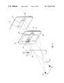
- FIG. 3Ais a perspective view of a visual display system including a display screen, a control box, a signal beacon, and a hand held remote control device.
- FIG. 3Bdepicts an example of a coordinate reference frame that may be used to describe the operation of the remote control devices of the invention.
- FIG. 4is an exploded perspective view of selected components of a remote control device, including a cylindrical lens, a gradient density filter, and a detector.
- FIG. 5is an exploded perspective view of the selected components of FIG. 4 and additionally depicts a second cylindrical lens with its accompanying gradient density filter and detector.
- FIG. 6is an exploded perspective view of selected components of the remote control device, including a first gradient density filter and a second gradient density filter rotated 180° with respect to each other.
- FIG. 7Ais an exploded perspective view of a tapered opening that selectively permits a signal to reach a detector.
- FIG. 7Bis an exploded perspective view of selected components of a remote control device depicting a tapered mask that selectively permits a signal to reach a detector.
- FIG. 8is an exploded perspective view of selected components of a further embodiment of a remote control device according to the invention.
- the cylindrical lenses of FIG. 5are replaced with elongated openings.
- FIG. 9Ais a flow diagram illustrating a method for positioning and moving a cursor according to the invention.
- FIG. 9Bis a flow diagram depicting an alternative method for positioning and moving the cursor.
- FIG. 10is a schematic diagram of components of a visual display system according to the invention.
- FIG. 11is a schematic diagram of a control box used to position a cursor according to the invention.
- FIG. 12Ais a perspective view of the visual display system of FIG. 3A , depicting the response of the cursor when the remote control device is rotated about its central axis.
- FIG. 12Bis a perspective view of an embodiment of a visual display system using two beacons, and further shows the response of the cursor when the remote control device is rotated about its central axis.
- the present inventionis directed to input devices used to select the position of a cursor or to select another function on a display screen by manually pointing, rotating, and moving the input device in three-dimensional space.
- an electromagnetic signalis emitted from a distant location and is received by the remote control device.
- the signalhas an incident direction as it is received by the remote control device. Changes in the angular displacement between a selected axis of the remote control device and the incident direction are detected and transmitted to a processor in a control box.
- the transmitted informationis used to select and move the position of a cursor on the display screen or to generate another selected function.
- the remote control device of the present inventionmay be used in connection with a wide variety of display screens and visual display systems, including interactive information systems.
- the remote control devicemay be used with personal computers, multimedia presentations, video and computer games, and the like. It has been found that the remote control devices of the present invention are particularly useful in interactive information systems using a conventional television screen.
- the remote control devicemay be used to select the position of a cursor on a Web page or another Internet application that is displayed on a television screen. It should be understood that the specific embodiments disclosed herein directed to interactive information systems using a conventional television screen are presented by way of example and not by limitation.
- the remote control devicesare used in a system known as WebTVTM (WebTV), which uses a conventional television screen for displaying information and browsing the Web, and which uses standard telephone lines, Integrated Services Digital Network (ISDN) lines, or the like to connect to the Internet or other wide area networks.
- WebTVTMWebTV
- ISDNIntegrated Services Digital Network
- FIG. 1illustrates a configuration of a WebTV network according to one embodiment.
- Multiple WebTV clients 1communicate with a modem pool 2 by means of direct-dial, bi-directional data connections 120 , which may be telephone lines, ISDN connections, or any other suitable communications channel.
- Modem pool 2may be any conventional modem pool, such as those that are currently used for providing access to the Internet and other wide area networks.
- modem pool 2may be provided by a local Internet Service Provider (ISP).
- ISPInternet Service Provider
- modem pool 2may be coupled to a number of remote servers 4 via a conventional network infrastructure 3 , such as the Internet.
- a WebTV systemmay be also supported by a WebTV server 5 , which is dedicated to providing information specifically to WebTV clients 1 . Accordingly, a WebTV client 1 may use telephone or ISDN connections to communicate with either modem pool 2 or WebTV server 5 .
- Control box 10may be either a self-contained unit or built into a television set. Control box 10 uses hardware and software for providing the user with a graphical user interface, by which the user can access the WebTV network services, browse the Internet, send and receive e-mail, and otherwise access the Internet.
- Operation of the WebTV client systemis controlled by a Central Processing Unit (CPU) 124 , which is coupled to an Application-Specific Integrated Circuit (ASIC) 122 .
- CPU 124executes software designed to implement features of the WebTV client system, including some of the features of the present invention.
- ASIC 122contains circuitry which is used to implement certain functions of the WebTV client system.
- ASIC 122is coupled to an audio digital-to-analog converter 132 and to a video encoder 134 , which provide audio and video output, respectively, to display screen 12 (seen in FIG. 3A ).
- An IR interface 24detects IR signals transmitted by remote control device 14 (seen in FIG. 3A ) and, in response, provides corresponding electrical signals to ASIC 122 .
- the signals transmitted by remote control device 14may be selected from another suitable region of the spectrum.
- a standard telephone modem 136 and an ISDN modem 140are coupled to ASIC 122 to provide connections 120 a and 120 b , respectively, to modem pool 2 and, via the Internet 3 , to remote servers 4 . While the system illustrated in FIG. 2 includes both a telephone modem and an ISDN modem, either one of these devices is sufficient to support a WebTV client system.
- modems 136 and 140may be supplemented or replaced with a cable television modem or another suitable communications device.
- communication with server 5may instead be established using a token ring or Ethernet connection.
- ROMRead-Only Memory
- flash memory 126 bFlash memory 126 b
- RAMRandom Access Memory
- Mask ROM 126 ais non-programmable and provides storage of program instructions and data.
- Flash memory 126 bmay be a conventional flash memory device that can be programmed and erased electronically. Flash memory 126 b provides storage of the browser software as well as data.
- a mass storage device 138is included in control box 10 and coupled to ASIC 122 . The mass storage device 138 may be used to input software or data to the client or to download software or data received over network connection 120 a or 120 b .
- Mass storage device 138may included any suitable medium for storing computer-executable code, such as magnetic disks, optical disks, and the like.
- control box 10is but one example of processing means for receiving data from the remote control devices of the invention and for generating a cursor in response to the data.
- the application software and associated operating system softwareare stored in flash memory 126 b , or instead may be stored in any other suitable memory device, such as mask ROM 126 a or mass storage device 138 .
- the computer-executable instructions that, according to one embodiment of the invention, are used to control a cursor on a display screen and to otherwise display informationare executed by CPU 124 .
- CPU 124executes sequences of instructions contained in one or more of mask ROM 126 a , flash memory 126 b , and RAM 128 to perform certain steps of the present invention that will be more specifically disclosed hereinafter.
- FIG. 3Adepicts but one example of the physical configuration of the elements of a client portion of a WebTV system or another preferred interactive information system and the general manner in which movement of a remote control device is linked to corresponding movement of a cursor.
- Control box 10may include the components illustrated in FIG. 2 and is ordinarily positioned in the line of sight of a user 16 .
- Control box 10is often placed on or near a television set that includes display screen 12 so that the action of pointing remote control device 14 at control box 10 is at least roughly equivalent to pointing remote control device 14 at display screen 12 .
- control box 10may instead positioned at a separate location from display screen 12 .
- Remote control device 14allows user 16 to communicate information to control box 10 from a remote location.
- remote control device 14may allow a user 16 to be seated at an opposite side of a room from display screen 12 .
- Remote control device 14may be a device specifically dedicated for the cursor-positioning functions disclosed herein or instead may be a multifunction device that supplies other information to control box 10 .
- remote control device 14may be a conventional remote control device that has been adapted to perform the cursor-positioning functions disclosed herein.
- the angular orientation and the angular movement of remote control device 14are used to position and move a cursor 18 on display screen 12 or to generate any other selected function on display screen 12 .
- Examples of other selected functionsinclude drawing, scrolling a computer-generated page, and identifying a menu selection, among any number of alternatives.
- the angular orientation and movement of remote control device 14are determined by using a signal 20 generated by a beacon 22 .
- Signal 20may consist of electromagnetic radiation primarily from the infrared region of the spectrum. Alternatively, the electromagnetic radiation of signal 20 may be selected from the radio frequency or any other suitable region of the spectrum.
- FIG. 3Adepicts signal 20 traveling from beacon 22 to remote control device 14 .
- beacon 22emits signal 20 in all directions that are within the line of sight of beacon 22 .
- signal 20may need to be distinguished by remote control device 14 from background sources of radiation. Accordingly, signal 20 may be amplitude modulated by methods known in the art.
- Remote control device 14communicates with control box 10 by means of electromagnetic signals selected from the infrared region of the spectrum or alternatively from the radio frequency or other suitable region of the spectrum.
- Control box 10includes a receiver 24 that detects the transmitted data 26 sent from remote control device 14 .
- Methods of transmitting data from a remote control device to a set top box using infrared or other electromagnetic signalsare well known in the art.
- FIG. 3Aalso depicts an example coordinate reference frame for remote control device 14 in order that the coordination of movement between remote control device 14 and cursor 18 may be further described and understood.
- the origin of the coordinate frameis defined to be at a known location with respect to remote control device 14 . Such known location may be, for example, within or near remote control device 14 . As another example, the origin may be at or near a location that detects signal 20 .
- the X axisis herein defined to be coaxial with the central axis of remote control device 14 . Furthermore, the Y axis and the Z axis each extends from the origin at right angles relative to the other axes.
- the foregoing coordinate reference frameis herein defined to be fixed with reference to remote control device 14 . In particular, rotation or translation of remote control device 14 is accompanied by corresponding rotation or translation of the coordinate reference frame. Other coordinate reference frames may be used and the coordinate reference frame of FIG. 3A is provided simply by way of example.
- FIG. 3Adepicts an X axis that passes through beacon 22 , a horizontal Y axis, and a vertical Z axis. It should be understood, however, that the coordinate reference frame and the directions of the respective axes are arbitrary, and that the operation of the remote control device could be equally described with respect to other coordinate reference frames.
- the X axisdoes not need to be aligned with the central axis of remote control device 14 , but instead may be any other selected axis of remote control device 14 .
- non-orthogonal coordinate framesmay also be used.
- Cursor 18is positioned on display screen 12 , which is defined herein to include a secondary coordinate system.
- the Y′ axisis defined as being horizontal and the Z′ axis is defined as being vertical as depicted in FIG. 3A .
- this coordinate frameis presented by way of example, and not by limitation.
- Signal 20is received by remote control device 14 at or near the origin of the coordinate reference frame. Accordingly, signal 20 has an incident direction at remote control device 14 that may be defined relative to the coordinate reference frame. In the example illustrated in FIG. 3A , the incident direction of signal 20 is substantially parallel to the X axis, and is but one example of the incident directions that are possible.
- remote control device 14As remote control device 14 is rotated or translated, the incident direction of signal 20 generally changes with respect to the coordinate reference frame.
- Remote control device 14detects the angular displacement between a selected axis of remote control device 14 , which in this example is collinear with the X axis, and the incident direction of signal 20 .
- angular displacementmay have a value of zero if the incident direction of signal 20 is parallel to the selected axis. It should also be noted that the measurements made by the remote control device could be accurately and interchangeably described as specifying the “incident direction” of signal 20 , the “angular displacement” between the selected axis of the remote control device and the incident direction of signal 20 , or the “angular orientation” of remote control device 14 .
- a mapping functionmay include a scale factor of a selected value that proportionally links rotation of the remote control device through a certain angle to corresponding movement of the cursor through a specified distance.
- control box 10translates the foregoing rotation into movement of cursor 18 in the Y′ axis.
- rotation of remote control device 14 in the XZ plane and about the Y axismay result in movement of the cursor 18 in the Z′ direction.
- the mapping functionmay instead translate movement of remote control device 14 into movement of cursor 18 according to any other desired relationship.
- the mapping functionmay be advantageously adjusted as desired such that rotation of remote control device 14 through a given amount may result in either a relatively small or relatively large displacement of cursor 18 .
- the scale factor that correlates the relative movement of remote control device 14 and cursor 18may be selected by the user after experimentation so that cursor 18 responds in a comfortable manner.
- mapping functions used with the inventionmay have any desired level of complexity.
- the mapping functionmay be dynamically modified according to the particular task a user is performing or the particular region of the display screen at which the cursor is located. For example, in a text-editing window, it is sometimes difficult to extend a text selection within a horizontal line without unintentionally slipping the cursor into an adjacent line above or below. This difficulty can be reduced by modifying the vertical scaling independent of the horizontal scaling when a user enters a text editing mode. Of course, other modifications of the mapping functions may be desirable, and are encompassed by the invention.
- the remote control devices 14 of the inventionare generally capable of detecting the incident direction of signal 20 about two nonparallel axes.
- the apparent position of beacon 22may be uniquely specified by defining a coordinate reference frame and by identifying components of the incident direction of signal 20 about two nonparallel axes. It should be noted that the apparent position of beacon 22 includes not only the incident angle ⁇ , but also the declination ⁇ of beacon 22 as measured about the X axis. An apparent position of beacon 22 that is specified by ⁇ and ⁇ is also uniquely specified by angle ⁇ Y measured about the Y axis and angle ⁇ Z measured about the Z axis.
- angle ⁇ Ymay be identified by performing a normal projection of beacon 22 and signal 20 onto the XZ plane and measuring the resulting angle ⁇ Y .
- angle ⁇ Zmay be identified by performing a normal projection of beacon 22 and signal 20 onto the XY plane and by measuring the resulting angle ⁇ Z .
- Other coordinate framescan be used with the invention, and may use different metrics to describe the incident angle.
- an embodiment of the remote control devices of the inventionincludes means for selectively projecting and/or focusing a portion of signal 20 onto a surface of the remote control device so that rotation about the Y and the Z axes may be measured.
- Such meansmay be optical in nature when signal 20 is an infrared or other optical signal.
- RF signalswill require different means.
- FIG. 12Ashows remote control device 14 and the system of FIG. 3A from the perspective of a user of the system.
- remote control device 14has been rotated about it central axis, thereby offsetting the Z axis and the Y axis from the vertical and horizontal planes, respectively.
- the resulting motion 21 of cursor 18is generally diagonal across display screen 12 .
- vertical motion of remote control device 14results in diagonal movement of cursor 18 .
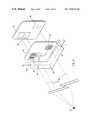
- FIG. 12BRemote control device 14 of FIG. 12B and the associated system are modified such that the coordinate reference frame may be described as being fixed with respect to display screen 12 .
- two (or more) beaconsare positioned in a known spatial relationship one with another.
- beacons 22 a and 22 bwhich emit signals 20 a and 20 b , respectively, are positioned near display screen 12 .
- the remote control device 14separately monitors the apparent position of beacons 22 a and 22 b by differentiating between the signals that are emitted from each of the beacons. The differentiation may be accomplished, for example, by alternatingly activating beacon 22 a and beacon 22 b or by modulating the beacon signals at different frequencies or at offset frequencies.
- the system of the inventionidentifies the horizontal plane or any other reference plane that is fixed with respect to the two beacons.
- the system of this embodimentis able to continue to monitor the relative position of the horizontal plane or the other reference plane.
- the systemcompensates for rotation of remote control device about its central axis as desired.
- the embodiment of FIG. 12Ballows the cursor to respond to motion of remote control device 14 in the manner illustrated.
- motion 23 of remote control device 14 in the horizontal planemay be translated into horizontal movement 25 of cursor 18 .
- the dual beacon system of FIG. 12Bis also capable of controlling motion of the cursor as depicted in FIG. 12A .
- beacons 22 a and 22 bdo not need to be positioned in the same elevation, but instead may be positioned relative one to another in substantially any axis or plane. Moreover, this embodiment supports another optional feature, in which the system monitors the angle subtended, from the point of view of remote control device 14 , by beacons 22 a and 22 b . Because beacons 22 a and 22 b are positioned in a known relationship with respect to display screen 12 , the angle subtended by the two beacons can be used to calculate the angle subtended by the display screen. This information may then be used to adjust the mapping function that translates motion of remote control device 14 into movement of cursor 18 .
- the scale factor that is used according to one implementation of the invention to convert a given angular motion of remote control device 14 into a linear motion of cursor 18 of a particular distancemay be adjusted based on the angle subtended by the display screen 12 .
- cursor 18responds to motion of remote control device 14 in a comfortable manner, without requiring excessive hand or arm motion by the user.
- Such automatic adjustment of the scale factoreliminates a calibration operation, used in other implementations of the invention, which requires the user to adjust the response of the cursor to a comfortable level, depending on the distance of the user from the display screen.
- a cylindrical lensis one example of the means for selectively projecting and/or focusing the signal, and may be used to focus a portion of signal 20 in a generally linear region 30 of a filter panel 32 in the remote control device.
- Cylindrical lens 28is a suitable optical device according to the invention because a properly positioned cylindrical lens 28 focuses substantially parallel rays in a generally linear region that has a longitudinal axis parallel to the cylindrical axis of the cylindrical lens 28 . It is recognized that cylindrical lenses generally do not tightly focus all light passing therethrough to a very narrow linear region. For example, light passing through the far left or the far right region of cylindrical lens 28 of FIG. 4 may be refracted and projected outside of the generally linear region 30 . However, cylindrical lens 28 focuses light passing therethrough at a significantly higher intensity on linear region 30 than the adjacent regions.
- FIG. 4also illustrates the manner in which the projected image generated by cylindrical lens 28 at the generally linear region 30 is translated across filter panel 32 as the remote control device is rotated about the Z axis.
- the imageshifts to a second generally linear region 30 ′ and retains a longitudinal axis parallel with the cylindrical axis of cylindrical lens 28 .
- this embodiment of the remote control devices of the inventionfurther includes an optical filtering structure that selectively removes a portion of the electromagnetic radiation from projected signal 20 depending on the angular position of the remote control device about the Z axis.
- filtering structureis intended to extend to any structure that permits a varying amount of electromagnetic radiation from a signal to reach a detector, depending on the angular position of the remote control device.
- the physical processes used by “filtering structures”include, but are not limited to, projection, absorption, focusing, reflection, refraction, and combinations of the foregoing.
- a filtering structuremay also include a selected shape, dimension, or configuration of a detector itself, such that the detector receives varying amounts of a signal as the remote control device is rotated.
- Any of the filtering structures disclosed hereinare to be understood as examples of filtering means for selectively reducing the amount of electromagnetic radiation within signal 20 in response to the angular orientation of the remote control device.
- gradient density filter 34which may be positioned on filter panel 32 such that the gradient axis thereof is oriented perpendicular to the cylindrical axis of cylindrical lens 28 .
- Gradient density filter 34progressively permits more of signal 20 to pass therethrough as the generally linear region 30 shifts along the gradient axis. For example, at a first end 35 of gradient density filter 34 , little or none of signal 20 is permitted to pass therethrough. At the opposite second end 37 of gradient density filter 34 , most or all of signal 20 is allowed to pass therethrough. In the segment between first end 37 and second end 38 , gradient density filter 34 progressively allows a greater portion of signal 20 to pass therethrough.
- receiving means for receiving signal 20is positioned therebehind.
- An example of the receiving meansis a photosensitive detector 36 that outputs an electrical signal in response to a measured amount of electromagnetic radiation.
- detector 36is shown displaced from filter panel 32 . In practice, however, detector 36 and filter panel 32 are often much closer together, and may be in direct contact.
- detector 36When detector 36 is used in connection with gradient density filter 34 , it measures varying amounts of electromagnetic radiation depending on the angular position of the remote control device about the Z axis and the corresponding position of generally linear region 30 . For example, in FIG.
- detector 36measures a lesser amount of electromagnetic radiation when signal 20 falls upon a first region 40 than when it falls upon a second region 40 ′. In this manner, the amount of radiation measured by detector 36 is a function of the angular position of the remote control device about Z axis in the sense that the measured amount of radiation predictably changes during rotation of the remote control device.
- a cylindrical lens 28 and the associated gradient density filter 34 and detector 36 of FIG. 4are an example of means for measuring a first component of the incident direction of signal 20 about one axis, which corresponds, for example, to ⁇ Z of FIG. 3A .
- Other examples of such meansmay include linear or planar detector arrays that include a plurality of discrete detectors and are adapted to measure angular displacement based on the relative amount of incident energy falling on each of the detectors in the array. When detector arrays are used, gradient filters and/or lenses may not be necessary, depending on the particular configuration.
- FIG. 5depicts one system for measuring the incident direction about two axes.
- FIG. 5illustrates a first cylindrical lens 28 with its associated first gradient density filter and a first detector.
- the remote control devicealso includes a second cylindrical lens 42 , second gradient density filter 44 and a second detector 46 , which thereby constitute one example of means for measuring a second component of the incident direction of signal 20 about the Y axis.
- the foregoing lenses, filters and detectorsare but one example of orientation means for establishing an initial angular orientation of the remote control device upon activation thereof.
- the detectors disclosed hereinconstitute but one example of detecting means for receiving and detecting an amount of electromagnetic radiation within signal 20 .
- the amount of electromagnetic radiation measured by detectors 36 and 46depends on the incident direction of signal 20 with respect to the Z and the Y axes. It can also be understood that the amount of radiation detected by detectors 36 and 46 is generally proportional to the apparent intensity of beacon 22 . Thus, rotating the remote control device and changing the apparent intensity of beacon 22 may each have the same effect on detectors 36 and 46 .
- One way in which the apparent intensity of beacon 22 may change, perhaps unintentionally,is increasing or decreasing the distance between the remote control device and beacon 22 .
- the remote control devices of the inventionmay include at least one intensity detector 48 .
- intensity detector 48is accompanied by an optical filter 50 that permits a uniform proportion of signal 20 to pass therethrough regardless of the incident direction of signal 20 .
- the output of detector 48may be used to normalize the outputs of detectors 36 and 46 in order to eliminate the variability introduced by changes of the apparent intensity of beacon 22 .
- the output of detector 36may be divided by the output of detector 48 in order to yield a ratio that uniquely defines the incident direction of signal 20 measured about the Z axis, regardless of the apparent intensity of beacon 22 .
- first cylindrical lens 28is accompanied by a first gradient density filter 34 and an opposing second gradient density filter 52 .
- the gradient density filtersare opposing in the sense that the gradient axis of second gradient density filter 52 is rotated about 180° from the gradient axis of filter 34 .
- This configuration of filtersprovides that, regardless of the apparent intensity of beacon 22 , the ratio of the output of detector 36 to the output of detector 54 uniquely specifies the incident direction of signal 20 measured about the Z axis.
- each cylindrical lens of FIG. 5may be accompanied by one intensity detector 48 .
- other combinations of the optical structures disclosed hereincan be used to identify the apparent intensity of beacon 22 and to normalize the output of the detectors with respect thereto.
- FIGS. 7A and 7Billustrate alternative structures that correspond to the filtering means of the invention.
- a wedge shaped opening 56is formed in a mask 57 that otherwise covers detector 36 .
- a varying amount of signal 20is measured by detector 36 .
- FIG. 7Bdepicts a wedge shaped masking structure 58 that overlies a portion of detector 36 in order to selectively absorb a portion of signal 20 depending on the incident direction thereof.
- other filtering structuressuch as reflective or refractive devices may be used to selectively remove radiation from signal 20 .
- a tapered reflective surfacemay be positioned to selectively reflect signal 20 onto an associated detector.
- the means for measuring the first component of the angular displacement of the remote control device and the means for measuring the second component of the angular displacementmay alternatively use structures other than the filtering structures disclosed herein.
- the filtering structuresmay be replaced with a mask or grating that is striped or otherwise patterned so as to produce a countable pulse as the remote control device is rotated.
- Another optionincludes using a binary-encoded mask and a number of detectors, one per bit, that allows digital detection of the angular orientation of the remote control device to a finite precision.
- the foregoing alternativesare typically more expensive and difficult to implement than embodiments using filtering structures.
- the cylindrical lenses of FIGS. 4 and 5are replaced with other structures for selectively projecting signal 20 onto a surface.
- the means for selectively projecting and/or focusing a portion of signal 20may include a first elongated opening 58 and a second non-parallel elongated opening 60 .
- Such elongated openingsmay be used to project a portion of signal 20 onto generally linear regions 62 and 64 .
- the configuration of FIG. 8generates a region of maximum intensity within generally linear regions 62 and 64 that is sufficiently predictable to be used with the invention.
- components of the incident direction of signal 20 about the Y axis and the Z axismay be uniquely identified by using detectors positioned behind gradient density filters 34 and 44 .
- the output of the detectorsmay need to be normalized with respect to the apparent intensity of beacon 22 in much the same manner as illustrated in FIG. 5 or 6 .
- the elongated openings, gradient density filters, and detectors of FIG. 8are presented as alternative examples of means to measure a first component and a second component of the angular displacement of the remote control device about the Y and the Z axes, respectively. Furthermore, the entire structure illustrated in FIG. 8 is another example of orientation means for establishing an initial angular orientation of the remote control device upon activation thereof.
- FIGS. 9A and 9Bare flow diagrams that set forth the manner in which the visual display system of the invention may generate and position a cursor in response to the angular orientation measurement of the remote control device.
- angle detectionis initiated in a first step 66 by setting the remote control device to an active state by one of any number of events. For example, a user may depress a button to indicate that a cursor is to be generated on the display screen.
- the remote control devicemay be automatically activated upon being moved or pointed. This may be performed by including motion sensors within the remote control device or by other suitable means.
- the remote control devicemay continually remain in an active state. This may be less preferable than other options, however, because a continually active state may require greater power requirements than are available. Because the remote control devices of the invention may be self contained units powered by batteries, it may be preferable to limit the amount of time that the remote control device is actively monitoring angular orientation in order to conserve energy resources.
- the remote control devicemay detect, in step 68 , the initial angular orientation according to the methods disclosed herein.
- the information corresponding to the initial angular orientationis transmitted to the control box, which, in step 70 , sets a cursor at an initial position on the display screen. Accordingly, under the method depicted in FIG. 9A , the initial cursor position is determined by the initial angular orientation of the remote control device.
- step 72is conducted, in which the user moves the remote control device as desired in order to move the cursor.
- the remote control devicedetects the new orientation according to methods disclosed herein, as shown in step 74 .
- the raw angular orientation informationmay be used in step 76 to calculate the angular displacement of the remote control device in one of at least two possible ways.
- the angular displacementmay be calculated with respect to the initial angular orientation of the remote control device.
- the angular displacementmay be calculated with respect to the immediately preceding angular orientation measurement. The foregoing calculation of angular displacement may be conducted in the remote control device before information is relayed to the control box or may be performed in the control box after raw data has been transmitted from the remote control device.
- the angular displacement informationis used to move or reposition the cursor in step 78 according to a predetermined set of mapping rules.
- the usercontinues to move the remote control device and angular orientation information is repeatedly gathered, transmitted, and calculated in order to repeatedly move the cursor position.
- the visual display system of the inventionuses discrete samples of the angular orientation information to move the cursor at a predetermined frequency.
- the usermay discontinue movement of the remote control device after the cursor has been moved to a desired location on the display screen or may deactivate the remote control device, thereby terminating the process of moving the cursor.
- FIG. 9Bsets forth a variation of the method described in FIG. 9A .
- step 66is followed by step 70 ′, in which the initial position of the cursor is set.
- step 70 ′ of FIG. 9Binvolves setting the cursor position independent of the initial angular orientation of the remote control device.
- the cursormay be positioned on the display screen at a predetermined location, such as the center of the screen, any other location on the screen, or the position at which the cursor was located at the time the remote control device was last deactivated.
- the cursormay be set to any predetermined active region of a computer-generated display on the display screen independent of the initial position of the remote control device.
- the process of FIG. 9Bfurther includes, in step 68 ′, detecting the initial angular orientation of the remote control device after the initial cursor position is set.
- the initial remote control orientationmay then be associated with the already-selected initial cursor position. Subsequent motion of the remote control device and measurement of the resultant angular orientation may be referenced to the initial angular orientation and initial cursor position in steps 72 , 74 , 76 , and 78 in the same manner as has been described above in reference to FIG. 9A .
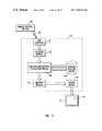
- FIG. 10illustrates the movement and processing of information and electrical and electromagnetic signals within a remote control device and an associated visual display system of the invention. It should be understood that the system and method of FIG. 10 are presented by way of example, and that other systems and methods, including alternatives disclosed herein, may be used according to the invention.
- beacon 22emits signal 20 which is received by remote control device 14 .
- signal 20passes through an optical bandpass filter 80 that selectively permits signal 20 to pass therethrough.
- Optical bandpass filter 80may include a coating on a surface substantially transparent to the desired wavelengths. The surface may be on remote control device 14 or may instead be positioned directly on substantially cylindrical lens 28 .
- signal 20After passing through optical bandpass filter 80 , signal 20 passes through substantially cylindrical lens 28 and is projected onto a first gradient density filter 34 and an opposing second gradient density filter 52 as depicted in FIG. 6 .
- the filtered signalfalls upon detectors 36 , which convert incident energy into an electrical current according to methods known in the art.
- detectors 36any other suitable configuration of lenses, filters, detectors, or other suitable structures may be used, including those of FIGS. 5 , 7 A, 7 B and 8 .
- Cylindrical lens 28 , gradient density filters 34 and 52 , and detectors 36are sufficient to provide data relating to the angular orientation of the remote control device about one axis.
- FIG. 10depicts the foregoing elements as they relate to only to one measurement channel, or one of the two non-parallel axes of measurement.
- the remote control devicemay further include a second cylindrical lens, one or more additional gradient density filters, and one or more additional detectors in a second measurement channel.
- the foregoing additional elementsare not depicted in FIG. 10 , but are used in order to measure the angular orientation of the remote control device about a second non-parallel axis.
- Beacon 22may amplitude modulate signal 20 at a selected frequency in order to further distinguish signal 20 from background sources of radiation.
- the modulation of signal 20typically causes electrical signals 82 produced by detectors 36 to have a corresponding frequency.
- Electrical signals 82are passed through a bandpass filter 84 selected to further reduce interference caused by background sources of radiation by suppressing frequencies other than the frequency of electrical signals 82 .
- informationis encoded in signal 20 in order to allow instructions 86 to be transmitted from processor 88 of control box 10 to remote control device 14 .
- Instructions 86may be used in any desired manner to modify or control selected functions of remote control device 14 .
- a suitable method of decoding the informationincludes combining and amplifying the filtered signals passing through bandpass filters 82 using a summing amplifier 90 according to known methods. Summing and amplifying the filtered electrical signals ensures that sufficiently strong signals are available regardless of the portion of gradient density filters 34 and 52 that are used.
- the amplified signal 92is then transmitted to a demodulator 94 to decode instructions 86 .
- instructions 86 ′may be used by a processor 96 in remote control device 14 or in any other desired manner.
- Normalizing module 102receives the integrated signals 100 and performs a division operation therebetween. The quotient generated by normalizing module 102 uniquely specifies the incident direction of signal 20 with respect to the cylindrical axis of substantially cylindrical lens 28 .
- normalization moduleis but one example of normalization means for adjusting the output of the detectors to substantially compensate for changes in the apparent intensity of signal 20 .
- Normalization module 102may be used whether the system for detecting the apparent intensity involves using opposing gradient density filters as shown in FIG. 10 , one or more apparent intensity detectors 48 of FIG. 5 , or suitable equivalent methods.
- An analog-to-digital converter 104receives the output of normalization module 102 and converts the output to a digital signal.
- Emitter 106converts the digital signal to a corresponding electromagnetic signal that is preferably selected from the infrared region of the spectrum or, alternatively, from the radio frequency or another suitable region.
- emitter 106is but one example of transmitting means for sending data to control box 10 .
- the transmitting meansmay include a cable that electronically connects remote control device 14 with control box 10 .
- the operations performed by the normalization module 102may be alternatively conducted within processor 88 of control box 10 . This could be accomplished by transmitting the raw data generated by detectors 36 from emitter 106 to control box 10 without any intermediate processing steps, or only with an analog-to-digital conversion at converter 104 .
- conducting the normalization process in processor 88reduces the required processing capabilities of remote control device 14 , thereby possibly reducing its energy requirements.
- transmitting raw data from remote control device 14may require more data streams, one per detector 36 , to be sent to the control box 10 than would be necessary if normalization had been already conducted.
- the optimal methodmay depend on the particular configuration of remote control device 14 and control box 10 , and the relative distribution of resources therebetween.
- Data 26 that is sent from remote control device 14is received by a receiver 24 on control box 10 .
- Data 26is then relayed to processor 88 which includes circuitry and/or executable code that translates data 26 into movement of cursor 18 on display screen 12 .
- processor 88includes circuitry and/or executable code that translates data 26 into movement of cursor 18 on display screen 12 .
- a user 16is able to view the position and movement of cursor 18 and to rotate or otherwise move remote control device 14 in order to cause cursor 18 to move to a desired position.
- the hand-eye feedback loop employed by user 16 in order to selectively position cursor 18is relatively intuitive when using the input devices according to the invention.
- the pointing actions and gestures used to manipulate remote control 14are universally understood and are easily adapted by a person learning to use the remote control devices.
- FIG. 11illustrates in greater detail but one example of the functional components of a control box 10 according to the invention.
- the functions of control box 10 depicted in FIG. 11may be executed using the architecture of control box 10 depicted in FIG. 2 , or by means of any other suitable circuitry and/or executable code. It should be recognized that the functional components of control box 10 depicted in FIG. 11 are primarily conceptual, and represent separate functions that may be performed by using hardware and/or software.
- the dataAfter data 26 is transmitted from emitter 106 to receiver 24 , the data optionally passes through a filtering module 107 , which may be advantageously included in control box 10 in order to at least partially eliminate the effects of unintended jitter or other small motion noise that would otherwise prevent smooth motion of the cursor.
- a remote control deviceunavoidably experiences unintended motion while being manually pointed and moved. For example, a user is unlikely to be able to hold a remote control device in a precisely fixed position or to rotate the remote control device through a perfectly smooth path. As a result, small deviations from the desired position of the remote control device are likely to be continually introduced into the system, and the data transmitted from the remote control device exhibits the equivalent of noise which represents the unintended movement.
- the noiseis generally at a high frequency compared to the movement of the cursor.
- filtering modulemay include devices that provide spatial and/or temporal filtering of the motion of the remote control device.
- a temporal low-pass filtermay be used to suppress high-frequency components of the signals, thereby at least partially compensating for natural motor jitter.
- Such filtersare well known in the art and include the so-called alpha filter and the alpha-beta filter. Other filtering algorithms may also be used.
- a spatial low-pass filtercan be used to improve the smoothness of motion represented on the display screen. For example, if the invention is used in a drawing application on the display screen, a spatial low-pass filter may enhance the smoothness of the lines and curves made by the user. It can be understood that the filtering devices are more effective when directed to unintended motion that is relatively small, or that has a magnitude less than a preselected threshold value.
- the filtering modulemay be used to replace the normalization module 102 of FIG. 10 .
- changes in the apparent intensity of signal 20are equivalent, from the standpoint of detectors 34 and 52 , to rotation of the remote control device. If the changes in apparent intensity are sufficiently small, however, such changes may be perceived by detectors 34 and 52 in the same way that motion jitter is perceived. For example, moving the remote control device slightly closer to or further away from beacon 22 introduces noise into the transmitted signals in much the same way as unintentional rotation.
- the resulting irregularities in the transmitted datamay be effectively reduced or eliminated using filtering module 107 .
- angular displacement module 108may be adapted to move cursor 18 only when the angular displacement of remote control device 14 has changed more than a minimum value.
- the minimal changeis considered to be caused by unintentional movement, and the cursor is not moved.
- the angular displacementchanges by a larger amount, which is unlikely to be the result of unintentional movement, the cursor is repositioned. This also has the effect of suppressing jitter on the signal.
- the angular displacement calculation module 108successively receives discrete sets of data corresponding to the angular orientation measured by the remote control device. Module 108 then compares the most recent set of data with previous angular position data stored in angular position buffer 110 .
- the angular position data stored in buffer 110may be updated with each new set of data received by control box 10 or may instead include the initial angular orientation of the remote control device that was detected upon activation of the system.
- angular position buffer 110is but one example of means for storing data relating to a reference angular orientation of the remote control device, and module 108 is but one example of means for comparing the reference angular orientation to the new angular orientation.
- mapping module 112is but one example of means for selecting a cursor position on the display screen in response to the angular movement of the remote control device.
- a predetermined set of mapping rulesmay be accessible to mapping module 112 and may be used to translate the angular displacement information into a corresponding position of cursor 18 .
- the mapping informationis sent to a cursor driver 114 that, in combination with display screen 12 , generates an updated position of cursor 18 according to methods that may be well-understood in the art.
- control box 10Much of the processing of data 26 that is hereby depicted in control box 10 may be instead conducted in the remote control device. However, it may be preferable to conduct a large proportion of the data processing in control box 10 so as to conserve energy resources of the remote control device.
- two beacons 22may be used in order to emit two signals 20 to the remote control device 14 . It can be understood that using two beacons 22 and one remote control device 14 is conceptually equivalent to defining three non-collinear points, which is sufficient to define a plane. In this manner, the defined plane may be detected by remote control device 14 and may be used as a fixed reference such that rotation of remote control device 14 in a horizontal plane corresponds to movement of cursor 18 in the Y′ direction, regardless of the angular position of the remote control device with respect to the X axis.
- the principles disclosed hereinmay be readily used to support two or more simultaneously-used remote control devices. This may allow two or more users to concurrently provide input to control box 10 and to generate concurrent selected functions on display screen 12 . This may be desirable in order to support interactive computer games on a television screen or any other computer applications in which concurrent users may be desired.
Landscapes
- Engineering & Computer Science (AREA)
- General Engineering & Computer Science (AREA)
- Theoretical Computer Science (AREA)
- Human Computer Interaction (AREA)
- Physics & Mathematics (AREA)
- General Physics & Mathematics (AREA)
- Multimedia (AREA)
- Signal Processing (AREA)
- Position Input By Displaying (AREA)
Abstract
Description
1. The Field of the Invention
The present invention relates to input devices for controlling the position of a cursor or the selection of information on a display screen. In particular, the present invention relates to a hand held remote control device that transmits data corresponding to its angular orientation to a processor, which in turn controls the position of a cursor in response to the transmitted data.
2. The Prior State of the Art
There have been developed many devices for allowing a user to interactively control the position of a cursor and to otherwise manipulate the display of information on computer display screens and the like. In general, these input devices function by transmitting data from the input device to a computer processor where the data is used to position a cursor on a display screen. Typically, input devices detect changes in their physical positioning or forces applied thereto by a user, which is then translated into changes in the position or velocity of a computer generated object on a display screen. Such manipulable input devices provide advantages over buttons such as those found in keyboards, in that the input devices frequently allow the user greater freedom to easily select information on a display screen.
A computer mouse is one example of an input device that has found widespread acceptance for positioning a cursor on a computer display screen. A mouse typically includes a freely rotatable ball partially encased in a housing so that the ball may be rolled over a flat surface. Sensors in the housing detect the rotation of the ball and transmit rotation information to the computer processor where it is converted into corresponding movement of the cursor. Computer mice have the advantage of allowing a user to precisely and easily position a cursor at a desired location on a computer display screen. Moreover, the relationship between movement of a mouse and corresponding movement of a cursor is relatively intuitive so that use of a mouse is easily learned.
Joysticks are another type of commonly used input devices in computer systems. A joystick typically includes a shaft-like handle that protrudes from a base and that may be easily gripped by the user. Force is applied onto the handle in one of any number of possible directions that are generally parallel to the horizontal plane. Sensors in the base of the joystick detect a direction and, optionally, the magnitude of the applied force, and transform this information into a corresponding response on the display screen. Joysticks are most widely used in computer applications where selection of direction is desired. For example, joysticks are especially useful in many computer games in order to select a direction of movement and, optionally, velocity of a computer generated object.
There have been developed many other computer input devices, including variations on computer mice and joysticks. For example, trackballs include a rotatable ball that is directly exposed so that it may be directly manipulated by the fingers or hands of a user. A touchpad includes a planar surface having sensors for detecting the positioning of a pointing device thereon and for transmitting this information to a computer processor. Furthermore, some computer input devices have been developed for representing three dimensional translation and/or rotational motion. In general, computer input devices convert physical displacement or applied forces to corresponding direction, position, or velocity of a computer generated object.
In recent years, interactive systems that use conventional television screens to display computer-generated or processed information have become increasingly common. For example, there are computer systems having Internet browsers that are adapted for use with conventional television screens. Moreover, one clear trend in the industry is the increasing integration of cable television, the Internet, other computer applications, and other information systems, whereby vast amounts of information may be instantaneously made available to a user. These systems require interaction between the user and a visual display, such as selection from among various menu options displayed on the television screen.
Frequently, interactive information systems displayed on a television screen are used in physical environments that are significantly different from the typical setting in which personal computers are used. For example, interactive information systems are often used in a living room setting where the user may be located on an opposite side of the room from the television screen. In addition, the user is ordinarily not seated at a table or a desk as is common for personal computer users. For this reason, the conventional practice of using a desktop keyboard and mouse for personal computers is not readily transferable to television-based interactive information systems. It can be easily understood that without an available flat surface, the use of a computer mouse is difficult or inappropriate in a living room setting.
As previously mentioned, one of the most promising uses for television-based interactive information systems is to provide Internet access on a conventional television screen. Perhaps the most common method for selecting information on the Internet is to control the position of the cursor with relation to a World Wide Web (Web) page. Because the use of a computer mouse is awkward, one solution has been to replace the cursor with a selection box that can be moved from one active are of a Web page to another by using directional arrow buttons. Under ideal conditions, directional arrow buttons work well and provide some benefits. In particular, the hardware is very simple and inexpensive and the directional arrow model is easily understandable even by very computer naive users. However, the directional arrow model fails when the Web page contains a Hypertext Markup Language (HTML) map which generally requires an actual pointing operation. In the past, the directional arrow model adapts to HTML maps by reverting to an arrow key driven cursor mode, which is functional but slow and cumbersome. There are also many cases where the directional arrow model breaks down. For example, orthogonal move instructions are ambiguous when adjacent active areas on a Web page are positioned diagonally one with another.
In addition to the foregoing difficulties that arise in basic Web page navigation using the directional arrow model, this model is not readily adaptable to other common and potential desirable activities and input modes. For example, directional arrow buttons are not adequate for real time interaction required for many computer games. Likewise, they are entirely impractical for drawing. In some cases, the directional arrow model is basically sound, but the vast number of locations to be traversed limit its practicability
Another factor that limits the types of input devices that can be practically used in television-based interactive systems is cost constraints. A primary reason why television-based Internet systems have become well accepted by consumers is the cost advantages they provide over personal computers. A typical television-based Internet system is primarily dedicated to providing interactive information on a television screen, thereby allowing the elimination or the reduction in size and cost of many of the components found in conventional personal computers. For example, because television-based Internet systems may not be intended for use with a wide number of computer applications, their hard drive requirements may be much less than those of personal computers. Moreover, the processing requirements are often different, which may allow television-based Internet systems to use processors that are less expensive than those of personal computers. Furthermore, users of television-based Internet systems usually do not purchase a dedicated monitor, but instead use an existing television screen.
It has been found that many consumers readily accept the Internet-dedicated nature of television-based Internet systems because of the vast cost savings compared to conventional personal computers. If a very expensive input device were to be sold with television-based Internet systems, a portion of the foregoing savings could be lost.
In view of the foregoing, it would be desirable to have an input device that can suitably allow a user to select a position of cursor on a conventional television screen. For example, it would be advantageous to provide an input device that allows a user to accurately position a cursor on a display screen in a living room environment. It would also be desirable to have an input device for positioning a cursor that is also relatively inexpensive.
The present invention relates to input devices for controlling the position of a cursor or the selection of information on a display screen. In particular, the present invention relates to a hand held remote control device that transmits data corresponding to its angular orientation to a processor, which in turn controls the position of a cursor in response to the transmitted data.
A user positions a cursor on a display screen by manually moving or rotating the remote control device. As the remote control device moves, data is transmitted to a control box that generates proportional movement of the cursor. Moving the remote control device to move a cursor is conceptually similar to a simple pointing gesture or to the manner in which a laser-pointing device projects a point of light on a wall.
In one application of the present invention, the remote control device is used in combination with a conventional television screen or another display screen and a set top control box that includes a processor for controlling the display of information on the television screen. In addition, the remote control device is preferably used with a beacon that emits a signal consisting of electromagnetic radiation selected, for example, from the infrared or radio frequency regions of the spectrum. The angular orientation of the remote control device is determined by sensors in the remote control device that detect information relating to the incident direction of the signal that is removed by the remote control device. In effect, the sensors measure the angular displacement between a selected axis of the remote control device and the incident direction of the signal. Accordingly, the invention extends to any input device that receives an electromagnetic signal from a distant source, determines angular orientation information from the electromagnetic signal, and makes this information available for the generation of a selected function on a display screen. In one method of measuring the angular displacement, the remote control device continually receives the signal from the beacon and measures, about two non-parallel axes, the angular displacement between the incident direction of the signal and the selected axis of the remote control device. The method may include, for example, projecting the signal through two cylindrical lenses each having a cylindrical axis parallel to the one of the two axes about which the angular displacement is measured.
The remote control device transmits information corresponding to the measured angular displacement to the television-based Internet system. The transmitted information may include raw data generated by the detectors or may include data that has already been processed by the remote control device. In either case, the angular displacement information may be used to determine the movement of a cursor on the display screen.
There may be several suitable methods for using the hand held remote control device to move the cursor. The first step generally includes activating the remote control device. This may be done by the user depressing a button on the remote control device, by pointing the remote control device at the beacon or another preselected region, or by any other suitable means. When the active state is selected, the processor in the television-based Internet system selects an initial position of the cursor in one of at least two possible ways. First, the cursor may be automatically set to the center of the screen or any other predetermined position. Alternatively, the cursor may be set at its last position on the display screen before the remote control device was previously deactivated. The initial position sets a baseline from which subsequent movement of the remote control device is measured. Second, the initial cursor position may be specified by the initial angular orientation of the remote control device. In this case, the remote control device makes an initial angular orientation measurement and relays the associated information to the control box.
After the initial postion of the cursor is set, the processor in the control box can move the cursor according to one of at least two methods. In the first method, the initial orientation of the remote control device is stored in the memory of the processor. Any subsequent displacement of the remote control device is compared to the original angular orientation, and the cursor is moved from its original position proportionally or according to any other desired mapping function. In the second method, each successive set of angular orientation information received by the control box is stored in the memory, and forms the baseline to which the following angular measurement is compared. For example, each time angular orientation information is related to the processor, the information is compared to the immediately preceding set of data. After the successive sets of data are compared, the cursor is moved from its then-current position to a new position according to the mapping function.
Because the remote control devices of the invention are often held in a user's hand and moved manually by the user, the movement of the remote control device and the corresponding angular orientation information unavoidably includes irregularities caused by shakiness, jittering, and the inherent inability to manually hold and move an object through a precisely predetermined path. Various filtering and sampling techniques may be used to at least partially reduce or prevent the irregular movement from translating into jumpy or shaky movement of the cursor.
The electromagnetic signal generated by the beacon may be amplitude modulated so that the remote control device may distinguish the signal from background sources. In addition, information may be encoded in the signal and may be extracted by a demodulator in the remote control device.
It can be appreciated that the remote control device and the accompanying system of the present invention overcome the limitations of the prior art. In particular, the remote control device is a pointing input device that can be used to specify the position of a cursor on a display screen. The present invention may be used to easily position a cursor on a television screen in a living room environment or in other situations where using a conventional computer mouse is impractical. Moreover, the sensors of the input device are relatively simple and may be incorporated in a standard remote control device at minimal additional cost, thereby making the invention cost effective in many situations.
Additional objects and advantages of the invention will be set forth in the description which follows, and in part will be obvious from the description, or may be learned by the practice of the invention. The objects and advantages of the invention may be realized and obtained by means of the instruments and combinations particularly pointed out in the appended claims. These and other objects and features of the present invention will become more fully apparent from the following description and appended claims, or may be learned by the practice of the invention as set forth hereinafter.
In order that the manner in which the above-recited and other advantages and objects of the invention are obtained, a more particular description of the invention briefly described above will be rendered by reference to specific embodiments thereof which are illustrated in the appended drawings. Understanding that these drawings depict only typical embodiments of the invention and are not therefore to be considered limiting of its scope, the invention will be described and explained with additional specificity and detail through the use of the accompanying drawings in which:
The invention is described below by using diagrams to illustrate either the structure or processing of embodiments used to implement the system and method of the present invention. Using the diagrams in this manner to present the invention should not be construed as limiting of its scope.
The present invention is directed to input devices used to select the position of a cursor or to select another function on a display screen by manually pointing, rotating, and moving the input device in three-dimensional space. In one embodiment of the invention, an electromagnetic signal is emitted from a distant location and is received by the remote control device. The signal has an incident direction as it is received by the remote control device. Changes in the angular displacement between a selected axis of the remote control device and the incident direction are detected and transmitted to a processor in a control box. The transmitted information is used to select and move the position of a cursor on the display screen or to generate another selected function.
It will be understood that the remote control device of the present invention may be used in connection with a wide variety of display screens and visual display systems, including interactive information systems. For example, the remote control device may be used with personal computers, multimedia presentations, video and computer games, and the like. It has been found that the remote control devices of the present invention are particularly useful in interactive information systems using a conventional television screen. For example, the remote control device may be used to select the position of a cursor on a Web page or another Internet application that is displayed on a television screen. It should be understood that the specific embodiments disclosed herein directed to interactive information systems using a conventional television screen are presented by way of example and not by limitation.
In one embodiment of the invention, the remote control devices are used in a system known as WebTV™ (WebTV), which uses a conventional television screen for displaying information and browsing the Web, and which uses standard telephone lines, Integrated Services Digital Network (ISDN) lines, or the like to connect to the Internet or other wide area networks.
The architecture of a control box of a WebTV client is illustrated inFIG. 2 .Control box 10 may be either a self-contained unit or built into a television set.Control box 10 uses hardware and software for providing the user with a graphical user interface, by which the user can access the WebTV network services, browse the Internet, send and receive e-mail, and otherwise access the Internet.
Operation of the WebTV client system is controlled by a Central Processing Unit (CPU)124, which is coupled to an Application-Specific Integrated Circuit (ASIC)122.CPU 124 executes software designed to implement features of the WebTV client system, including some of the features of the present invention.ASIC 122 contains circuitry which is used to implement certain functions of the WebTV client system.ASIC 122 is coupled to an audio digital-to-analog converter 132 and to avideo encoder 134, which provide audio and video output, respectively, to display screen12 (seen inFIG. 3A ). AnIR interface 24 detects IR signals transmitted by remote control device14 (seen inFIG. 3A ) and, in response, provides corresponding electrical signals toASIC 122. Alternatively, the signals transmitted byremote control device 14 may be selected from another suitable region of the spectrum. Astandard telephone modem 136 and anISDN modem 140 are coupled toASIC 122 to provideconnections modem pool 2 and, via theInternet 3, toremote servers 4. While the system illustrated inFIG. 2 includes both a telephone modem and an ISDN modem, either one of these devices is sufficient to support a WebTV client system. Furthermore, in other embodiments of a WebTV client system, modems136 and140 may be supplemented or replaced with a cable television modem or another suitable communications device. In addition, communication withserver 5 may instead be established using a token ring or Ethernet connection.
Also coupled toASIC 122 is a mask Read-Only Memory (ROM)126a, aflash memory 126b, and a Random Access Memory (RAM)128.Mask ROM 126ais non-programmable and provides storage of program instructions and data.Flash memory 126bmay be a conventional flash memory device that can be programmed and erased electronically.Flash memory 126bprovides storage of the browser software as well as data. In one embodiment, amass storage device 138 is included incontrol box 10 and coupled toASIC 122. Themass storage device 138 may be used to input software or data to the client or to download software or data received overnetwork connection Mass storage device 138 may included any suitable medium for storing computer-executable code, such as magnetic disks, optical disks, and the like.
One use for the above-described components ofcontrol box 10 is to support and execute applications software including a Web browser. In particular, the applications software typically includes computer-executable code for responding to data received from the remote control device and for generating and moving a cursor on the display screen. Thus,control box 10 is but one example of processing means for receiving data from the remote control devices of the invention and for generating a cursor in response to the data.
The application software and associated operating system software are stored inflash memory 126b, or instead may be stored in any other suitable memory device, such asmask ROM 126aormass storage device 138. The computer-executable instructions that, according to one embodiment of the invention, are used to control a cursor on a display screen and to otherwise display information are executed byCPU 124. In particular,CPU 124 executes sequences of instructions contained in one or more ofmask ROM 126a,flash memory 126b, andRAM 128 to perform certain steps of the present invention that will be more specifically disclosed hereinafter.
The angular orientation and the angular movement ofremote control device 14 are used to position and move acursor 18 ondisplay screen 12 or to generate any other selected function ondisplay screen 12. Examples of other selected functions include drawing, scrolling a computer-generated page, and identifying a menu selection, among any number of alternatives.
According to one embodiment of the invention, the angular orientation and movement ofremote control device 14 are determined by using asignal 20 generated by abeacon 22.Signal 20 may consist of electromagnetic radiation primarily from the infrared region of the spectrum. Alternatively, the electromagnetic radiation ofsignal 20 may be selected from the radio frequency or any other suitable region of the spectrum. For purposes of illustration,FIG. 3A depictssignal 20 traveling frombeacon 22 toremote control device 14. However, it is to be understood thatbeacon 22 emits signal20 in all directions that are within the line of sight ofbeacon 22. Depending on the environment, in order to detect the angular orientation ofremote control device 14 with respect tobeacon 22, signal20 may need to be distinguished byremote control device 14 from background sources of radiation. Accordingly, signal20 may be amplitude modulated by methods known in the art.
Asremote control device 14 is rotated or translated, the incident direction ofsignal 20 generally changes with respect to the coordinate reference frame.Remote control device 14 detects the angular displacement between a selected axis ofremote control device 14, which in this example is collinear with the X axis, and the incident direction ofsignal 20. As used herein, “angular displacement” may have a value of zero if the incident direction ofsignal 20 is parallel to the selected axis. It should also be noted that the measurements made by the remote control device could be accurately and interchangeably described as specifying the “incident direction” ofsignal 20, the “angular displacement” between the selected axis of the remote control device and the incident direction ofsignal 20, or the “angular orientation” ofremote control device 14.
Data corresponding to the detected angular displacement is transmitted to controlbox 10, where it is translated into movement ofcursor 18 according to a preselected mapping function. For example, a mapping function may include a scale factor of a selected value that proportionally links rotation of the remote control device through a certain angle to corresponding movement of the cursor through a specified distance.
As seen inFIG. 3A , rotation ofremote control device 14 in the XY plane and about the Z axis produces an angular displacement of the incident direction ofsignal 20 about the Z axis. In one example of a mapping function that may be used according to the invention,control box 10 translates the foregoing rotation into movement ofcursor 18 in the Y′ axis. Likewise, rotation ofremote control device 14 in the XZ plane and about the Y axis may result in movement of thecursor 18 in the Z′ direction. However, the mapping function may instead translate movement ofremote control device 14 into movement ofcursor 18 according to any other desired relationship.
The mapping function may be advantageously adjusted as desired such that rotation ofremote control device 14 through a given amount may result in either a relatively small or relatively large displacement ofcursor 18. For example, the scale factor that correlates the relative movement ofremote control device 14 andcursor 18 may be selected by the user after experimentation so thatcursor 18 responds in a comfortable manner.
The mapping functions used with the invention may have any desired level of complexity. The mapping function may be dynamically modified according to the particular task a user is performing or the particular region of the display screen at which the cursor is located. For example, in a text-editing window, it is sometimes difficult to extend a text selection within a horizontal line without unintentionally slipping the cursor into an adjacent line above or below. This difficulty can be reduced by modifying the vertical scaling independent of the horizontal scaling when a user enters a text editing mode. Of course, other modifications of the mapping functions may be desirable, and are encompassed by the invention.
Theremote control devices 14 of the invention are generally capable of detecting the incident direction ofsignal 20 about two nonparallel axes. As shown inFIG. 3B , the apparent position ofbeacon 22 may be uniquely specified by defining a coordinate reference frame and by identifying components of the incident direction ofsignal 20 about two nonparallel axes. It should be noted that the apparent position ofbeacon 22 includes not only the incident angle φ, but also the declination γ ofbeacon 22 as measured about the X axis. An apparent position ofbeacon 22 that is specified by φ and γ is also uniquely specified by angle θYmeasured about the Y axis and angle θZmeasured about the Z axis. To further illustrate, angle θYmay be identified by performing a normal projection ofbeacon 22 and signal20 onto the XZ plane and measuring the resulting angle θY. Likewise, angle θZmay be identified by performing a normal projection ofbeacon 22 and signal20 onto the XY plane and by measuring the resulting angle θZ. Other coordinate frames can be used with the invention, and may use different metrics to describe the incident angle.
The foregoing observation is important because these principles may be used to position and configure the sensors in remote control devices according to one embodiment of the invention. It should also be noted that while the X, Y, and Z axes ofFIG. 3B are mutually orthogonal, an apparent position ofbeacon 22 can be uniquely specified so long as the axes about which angles θYand θZare measured are nonparallel one to another.
In order to detect angles θYand θZofFIG. 3B , an embodiment of the remote control devices of the invention includes means for selectively projecting and/or focusing a portion ofsignal 20 onto a surface of the remote control device so that rotation about the Y and the Z axes may be measured. Such means may be optical in nature whensignal 20 is an infrared or other optical signal. RF signals will require different means. Although the example given below uses infrared or other optical signals to illustrate the operation of the invention, similar principles apply to other types of signals.
In view of the foregoing discussion and the embodiment depicted inFIGS. 3A and 3B , it can it can be understood that if a user were to rotate theremote control device 14 ofFIG. 3A about its central axis, or equivalently about the X axis, subsequent movement of the remote control device in the horizontal plane generally would not result in horizontal movement ofcursor 18. This feature of one embodiment of the invention is further illustrated inFIG. 12A , which showsremote control device 14 and the system ofFIG. 3A from the perspective of a user of the system. In particular,remote control device 14 has been rotated about it central axis, thereby offsetting the Z axis and the Y axis from the vertical and horizontal planes, respectively. Whenremote control device 14 is rotated in the horizontal plane as shown atreference number 19 inFIG. 12A , the resultingmotion 21 ofcursor 18 is generally diagonal acrossdisplay screen 12. Likewise, vertical motion ofremote control device 14 results in diagonal movement ofcursor 18.
While the above-described response of the remote control device to rotation about its central axis is entirely acceptable, and often preferable, some users in some situations may prefer an alternative embodiment, illustrated inFIG. 12B .Remote control device 14 ofFIG. 12B and the associated system are modified such that the coordinate reference frame may be described as being fixed with respect to displayscreen 12. In this embodiment, two (or more) beacons are positioned in a known spatial relationship one with another. For example,beacons display screen 12. Theremote control device 14 separately monitors the apparent position ofbeacons beacon 22aandbeacon 22bor by modulating the beacon signals at different frequencies or at offset frequencies.
By specifying and comparing the apparent position ofbeacons remote control device 14 undergoes rotation about its central axis, the system of this embodiment is able to continue to monitor the relative position of the horizontal plane or the other reference plane. Using the positional information relating tobeacons FIG. 12B allows the cursor to respond to motion ofremote control device 14 in the manner illustrated. In particular,motion 23 ofremote control device 14 in the horizontal plane may be translated intohorizontal movement 25 ofcursor 18. Of course, in the alternative, the dual beacon system ofFIG. 12B is also capable of controlling motion of the cursor as depicted inFIG. 12A .
In the embodiment illustrated inFIG. 12B ,beacons remote control device 14, bybeacons beacons screen 12, the angle subtended by the two beacons can be used to calculate the angle subtended by the display screen. This information may then be used to adjust the mapping function that translates motion ofremote control device 14 into movement ofcursor 18. For example, the scale factor that is used according to one implementation of the invention to convert a given angular motion ofremote control device 14 into a linear motion ofcursor 18 of a particular distance may be adjusted based on the angle subtended by thedisplay screen 12. As a result, regardless of the distance of the user fromdisplay screen 12,cursor 18 responds to motion ofremote control device 14 in a comfortable manner, without requiring excessive hand or arm motion by the user. Such automatic adjustment of the scale factor eliminates a calibration operation, used in other implementations of the invention, which requires the user to adjust the response of the cursor to a comfortable level, depending on the distance of the user from the display screen.
As illustrated inFIG. 4 , a cylindrical lens is one example of the means for selectively projecting and/or focusing the signal, and may be used to focus a portion ofsignal 20 in a generallylinear region 30 of a filter panel32 in the remote control device.Cylindrical lens 28 is a suitable optical device according to the invention because a properly positionedcylindrical lens 28 focuses substantially parallel rays in a generally linear region that has a longitudinal axis parallel to the cylindrical axis of thecylindrical lens 28. It is recognized that cylindrical lenses generally do not tightly focus all light passing therethrough to a very narrow linear region. For example, light passing through the far left or the far right region ofcylindrical lens 28 ofFIG. 4 may be refracted and projected outside of the generallylinear region 30. However,cylindrical lens 28 focuses light passing therethrough at a significantly higher intensity onlinear region 30 than the adjacent regions.
As seen inFIG. 4 , this embodiment of the remote control devices of the invention further includes an optical filtering structure that selectively removes a portion of the electromagnetic radiation from projectedsignal 20 depending on the angular position of the remote control device about the Z axis. As used herein, “filtering structure” is intended to extend to any structure that permits a varying amount of electromagnetic radiation from a signal to reach a detector, depending on the angular position of the remote control device. The physical processes used by “filtering structures” include, but are not limited to, projection, absorption, focusing, reflection, refraction, and combinations of the foregoing. Moreover, a filtering structure may also include a selected shape, dimension, or configuration of a detector itself, such that the detector receives varying amounts of a signal as the remote control device is rotated. Any of the filtering structures disclosed herein are to be understood as examples of filtering means for selectively reducing the amount of electromagnetic radiation withinsignal 20 in response to the angular orientation of the remote control device.
One example of a filtering structure isgradient density filter 34, which may be positioned on filter panel32 such that the gradient axis thereof is oriented perpendicular to the cylindrical axis ofcylindrical lens 28.Gradient density filter 34 progressively permits more ofsignal 20 to pass therethrough as the generallylinear region 30 shifts along the gradient axis. For example, at afirst end 35 ofgradient density filter 34, little or none ofsignal 20 is permitted to pass therethrough. At the oppositesecond end 37 ofgradient density filter 34, most or all ofsignal 20 is allowed to pass therethrough. In the segment betweenfirst end 37 and second end38,gradient density filter 34 progressively allows a greater portion ofsignal 20 to pass therethrough.
In order to detect the amount ofsignal 20 that passes throughgradient density filter 34, receiving means for receivingsignal 20 is positioned therebehind. An example of the receiving means is aphotosensitive detector 36 that outputs an electrical signal in response to a measured amount of electromagnetic radiation. For illustrative purposes,detector 36 is shown displaced from filter panel32. In practice, however,detector 36 and filter panel32 are often much closer together, and may be in direct contact. Whendetector 36 is used in connection withgradient density filter 34, it measures varying amounts of electromagnetic radiation depending on the angular position of the remote control device about the Z axis and the corresponding position of generallylinear region 30. For example, inFIG. 4 detector 36 measures a lesser amount of electromagnetic radiation whensignal 20 falls upon afirst region 40 than when it falls upon asecond region 40′. In this manner, the amount of radiation measured bydetector 36 is a function of the angular position of the remote control device about Z axis in the sense that the measured amount of radiation predictably changes during rotation of the remote control device.
Acylindrical lens 28 and the associatedgradient density filter 34 anddetector 36 ofFIG. 4 are an example of means for measuring a first component of the incident direction ofsignal 20 about one axis, which corresponds, for example, to θZofFIG. 3A . Other examples of such means may include linear or planar detector arrays that include a plurality of discrete detectors and are adapted to measure angular displacement based on the relative amount of incident energy falling on each of the detectors in the array. When detector arrays are used, gradient filters and/or lenses may not be necessary, depending on the particular configuration.
In order to uniquely specify the incident direction ofsignal 20, a second component is measured around a second nonparallel axis.FIG. 5 depicts one system for measuring the incident direction about two axes. In particular,FIG. 5 illustrates a firstcylindrical lens 28 with its associated first gradient density filter and a first detector. The remote control device also includes a secondcylindrical lens 42, secondgradient density filter 44 and a second detector46, which thereby constitute one example of means for measuring a second component of the incident direction ofsignal 20 about the Y axis. It is also to be understood that the foregoing lenses, filters and detectors are but one example of orientation means for establishing an initial angular orientation of the remote control device upon activation thereof. Moreover, the detectors disclosed herein constitute but one example of detecting means for receiving and detecting an amount of electromagnetic radiation withinsignal 20.
As shown inFIGS. 4 and 5 , the amount of electromagnetic radiation measured bydetectors 36 and46 depends on the incident direction ofsignal 20 with respect to the Z and the Y axes. It can also be understood that the amount of radiation detected bydetectors 36 and46 is generally proportional to the apparent intensity ofbeacon 22. Thus, rotating the remote control device and changing the apparent intensity ofbeacon 22 may each have the same effect ondetectors 36 and46. One way in which the apparent intensity ofbeacon 22 may change, perhaps unintentionally, is increasing or decreasing the distance between the remote control device andbeacon 22.
In order to compensate for the effects of a possible change in the apparent intensity ofbeacon 22, the remote control devices of the invention may include at least oneintensity detector 48. InFIG. 5 ,intensity detector 48 is accompanied by anoptical filter 50 that permits a uniform proportion ofsignal 20 to pass therethrough regardless of the incident direction ofsignal 20. The output ofdetector 48 may be used to normalize the outputs ofdetectors 36 and46 in order to eliminate the variability introduced by changes of the apparent intensity ofbeacon 22. For example, the output ofdetector 36 may be divided by the output ofdetector 48 in order to yield a ratio that uniquely defines the incident direction ofsignal 20 measured about the Z axis, regardless of the apparent intensity ofbeacon 22.
There are other ways to normalize the signals generated bydetectors 36 and46 or to otherwise eliminate the variability caused by changes in the apparent intensity ofbeacon 22. For example, inFIG. 6 , firstcylindrical lens 28 is accompanied by a firstgradient density filter 34 and an opposing secondgradient density filter 52. The gradient density filters are opposing in the sense that the gradient axis of secondgradient density filter 52 is rotated about 180° from the gradient axis offilter 34. This configuration of filters provides that, regardless of the apparent intensity ofbeacon 22, the ratio of the output ofdetector 36 to the output ofdetector 54 uniquely specifies the incident direction ofsignal 20 measured about the Z axis.
In a further alternative method of normalizing the detector output, each cylindrical lens ofFIG. 5 may be accompanied by oneintensity detector 48. Moreover, other combinations of the optical structures disclosed herein can be used to identify the apparent intensity ofbeacon 22 and to normalize the output of the detectors with respect thereto.
The means for measuring the first component of the angular displacement of the remote control device and the means for measuring the second component of the angular displacement may alternatively use structures other than the filtering structures disclosed herein. For example, the filtering structures may be replaced with a mask or grating that is striped or otherwise patterned so as to produce a countable pulse as the remote control device is rotated. Another option includes using a binary-encoded mask and a number of detectors, one per bit, that allows digital detection of the angular orientation of the remote control device to a finite precision. However, the foregoing alternatives are typically more expensive and difficult to implement than embodiments using filtering structures.
In another embodiment of the invention, the cylindrical lenses ofFIGS. 4 and 5 are replaced with other structures for selectively projectingsignal 20 onto a surface. For example, the means for selectively projecting and/or focusing a portion ofsignal 20 may include a firstelongated opening 58 and a second non-parallel elongated opening60. Such elongated openings may be used to project a portion ofsignal 20 onto generallylinear regions signal 20 is usually diffracted while passing throughelongated openings 58 and60 and is thereby projected onfilter panel 34 outside of the generallylinear regions FIG. 8 generates a region of maximum intensity within generallylinear regions signal 20 about the Y axis and the Z axis may be uniquely identified by using detectors positioned behind gradient density filters34 and44. Of course, the output of the detectors may need to be normalized with respect to the apparent intensity ofbeacon 22 in much the same manner as illustrated inFIG. 5 or6.
The elongated openings, gradient density filters, and detectors ofFIG. 8 are presented as alternative examples of means to measure a first component and a second component of the angular displacement of the remote control device about the Y and the Z axes, respectively. Furthermore, the entire structure illustrated inFIG. 8 is another example of orientation means for establishing an initial angular orientation of the remote control device upon activation thereof.
Alternatively, the remote control device may be automatically activated upon being moved or pointed. This may be performed by including motion sensors within the remote control device or by other suitable means. In yet another variation, the remote control device may continually remain in an active state. This may be less preferable than other options, however, because a continually active state may require greater power requirements than are available. Because the remote control devices of the invention may be self contained units powered by batteries, it may be preferable to limit the amount of time that the remote control device is actively monitoring angular orientation in order to conserve energy resources.
After angle detection is initiated, the remote control device may detect, instep 68, the initial angular orientation according to the methods disclosed herein. The information corresponding to the initial angular orientation is transmitted to the control box, which, instep 70, sets a cursor at an initial position on the display screen. Accordingly, under the method depicted inFIG. 9A , the initial cursor position is determined by the initial angular orientation of the remote control device.
After initially positioning the cursor and detecting the angular orientation,step 72 is conducted, in which the user moves the remote control device as desired in order to move the cursor. During or after being moved, the remote control device detects the new orientation according to methods disclosed herein, as shown instep 74. The raw angular orientation information may be used instep 76 to calculate the angular displacement of the remote control device in one of at least two possible ways. First, the angular displacement may be calculated with respect to the initial angular orientation of the remote control device. Second, the angular displacement may be calculated with respect to the immediately preceding angular orientation measurement. The foregoing calculation of angular displacement may be conducted in the remote control device before information is relayed to the control box or may be performed in the control box after raw data has been transmitted from the remote control device.
The angular displacement information is used to move or reposition the cursor instep 78 according to a predetermined set of mapping rules. The user continues to move the remote control device and angular orientation information is repeatedly gathered, transmitted, and calculated in order to repeatedly move the cursor position. Typically, the visual display system of the invention uses discrete samples of the angular orientation information to move the cursor at a predetermined frequency. Finally, the user may discontinue movement of the remote control device after the cursor has been moved to a desired location on the display screen or may deactivate the remote control device, thereby terminating the process of moving the cursor.
The process ofFIG. 9B further includes, instep 68′, detecting the initial angular orientation of the remote control device after the initial cursor position is set. The initial remote control orientation may then be associated with the already-selected initial cursor position. Subsequent motion of the remote control device and measurement of the resultant angular orientation may be referenced to the initial angular orientation and initial cursor position insteps FIG. 9A .
After passing throughoptical bandpass filter 80, signal20 passes through substantiallycylindrical lens 28 and is projected onto a firstgradient density filter 34 and an opposing secondgradient density filter 52 as depicted inFIG. 6 . Next, the filtered signal falls upondetectors 36, which convert incident energy into an electrical current according to methods known in the art. Alternatively, any other suitable configuration of lenses, filters, detectors, or other suitable structures may be used, including those ofFIGS. 5 ,7A,7B and8.
Optionally, information is encoded insignal 20 in order to allowinstructions 86 to be transmitted fromprocessor 88 ofcontrol box 10 toremote control device 14.Instructions 86 may be used in any desired manner to modify or control selected functions ofremote control device 14. If information is encoded insignal 20, a suitable method of decoding the information includes combining and amplifying the filtered signals passing throughbandpass filters 82 using a summingamplifier 90 according to known methods. Summing and amplifying the filtered electrical signals ensures that sufficiently strong signals are available regardless of the portion of gradient density filters34 and52 that are used. The amplifiedsignal 92 is then transmitted to ademodulator 94 to decodeinstructions 86. In this manner,instructions 86′ may be used by aprocessor 96 inremote control device 14 or in any other desired manner.
The filtered signals that have passed throughbandpass filters 84 are also directed tointegrators 98 that generateintegrated signals 100. Normalizingmodule 102 receives theintegrated signals 100 and performs a division operation therebetween. The quotient generated by normalizingmodule 102 uniquely specifies the incident direction ofsignal 20 with respect to the cylindrical axis of substantiallycylindrical lens 28. Thus, normalization module is but one example of normalization means for adjusting the output of the detectors to substantially compensate for changes in the apparent intensity ofsignal 20.Normalization module 102 may be used whether the system for detecting the apparent intensity involves using opposing gradient density filters as shown inFIG. 10 , one or moreapparent intensity detectors 48 ofFIG. 5 , or suitable equivalent methods.
An analog-to-digital converter 104 receives the output ofnormalization module 102 and converts the output to a digital signal.Emitter 106 converts the digital signal to a corresponding electromagnetic signal that is preferably selected from the infrared region of the spectrum or, alternatively, from the radio frequency or another suitable region. Thus,emitter 106 is but one example of transmitting means for sending data to controlbox 10. Alternatively, the transmitting means may include a cable that electronically connectsremote control device 14 withcontrol box 10.
The operations performed by thenormalization module 102 may be alternatively conducted withinprocessor 88 ofcontrol box 10. This could be accomplished by transmitting the raw data generated bydetectors 36 fromemitter 106 to controlbox 10 without any intermediate processing steps, or only with an analog-to-digital conversion atconverter 104. Of course, conducting the normalization process inprocessor 88 reduces the required processing capabilities ofremote control device 14, thereby possibly reducing its energy requirements. At the same time, however, transmitting raw data fromremote control device 14 may require more data streams, one perdetector 36, to be sent to thecontrol box 10 than would be necessary if normalization had been already conducted. The optimal method may depend on the particular configuration ofremote control device 14 andcontrol box 10, and the relative distribution of resources therebetween.
Using the foregoing methods, auser 16 is able to view the position and movement ofcursor 18 and to rotate or otherwise moveremote control device 14 in order to causecursor 18 to move to a desired position. The hand-eye feedback loop employed byuser 16 in order to selectively positioncursor 18 is relatively intuitive when using the input devices according to the invention. In particular, the pointing actions and gestures used to manipulateremote control 14 are universally understood and are easily adapted by a person learning to use the remote control devices.
Afterdata 26 is transmitted fromemitter 106 toreceiver 24, the data optionally passes through afiltering module 107, which may be advantageously included incontrol box 10 in order to at least partially eliminate the effects of unintended jitter or other small motion noise that would otherwise prevent smooth motion of the cursor. It can be understood that a remote control device unavoidably experiences unintended motion while being manually pointed and moved. For example, a user is unlikely to be able to hold a remote control device in a precisely fixed position or to rotate the remote control device through a perfectly smooth path. As a result, small deviations from the desired position of the remote control device are likely to be continually introduced into the system, and the data transmitted from the remote control device exhibits the equivalent of noise which represents the unintended movement. The noise is generally at a high frequency compared to the movement of the cursor.
To at least partially eliminate the noise introduced into the transmitted data, filtering module may include devices that provide spatial and/or temporal filtering of the motion of the remote control device. A temporal low-pass filter may be used to suppress high-frequency components of the signals, thereby at least partially compensating for natural motor jitter. Such filters are well known in the art and include the so-called alpha filter and the alpha-beta filter. Other filtering algorithms may also be used. Moreover, a spatial low-pass filter can be used to improve the smoothness of motion represented on the display screen. For example, if the invention is used in a drawing application on the display screen, a spatial low-pass filter may enhance the smoothness of the lines and curves made by the user. It can be understood that the filtering devices are more effective when directed to unintended motion that is relatively small, or that has a magnitude less than a preselected threshold value.
In certain circumstances, the filtering module may be used to replace thenormalization module 102 ofFIG. 10 . As previously disclosed, in the absence of anormalization module 102, changes in the apparent intensity ofsignal 20 are equivalent, from the standpoint ofdetectors detectors beacon 22 introduces noise into the transmitted signals in much the same way as unintentional rotation. Depending on the magnitude of the changes of the apparent intensity and the configuration of the filtering devices, the resulting irregularities in the transmitted data may be effectively reduced or eliminated usingfiltering module 107.
An alternative solution for at least partially eliminating the effects of unintended movement does not require filtering devices. Instead,angular displacement module 108,mapping module 112, or another suitable element ofcontrol box 10 may be adapted to movecursor 18 only when the angular displacement ofremote control device 14 has changed more than a minimum value. Thus, if a first sample and a second sample of the angular displacement differ one from another by less than a minimum value, the minimal change is considered to be caused by unintentional movement, and the cursor is not moved. On the other hand, when the angular displacement changes by a larger amount, which is unlikely to be the result of unintentional movement, the cursor is repositioned. This also has the effect of suppressing jitter on the signal.
After the optional step of filtering, the angulardisplacement calculation module 108 successively receives discrete sets of data corresponding to the angular orientation measured by the remote control device.Module 108 then compares the most recent set of data with previous angular position data stored inangular position buffer 110. The angular position data stored inbuffer 110 may be updated with each new set of data received bycontrol box 10 or may instead include the initial angular orientation of the remote control device that was detected upon activation of the system. In this manner,angular position buffer 110 is but one example of means for storing data relating to a reference angular orientation of the remote control device, andmodule 108 is but one example of means for comparing the reference angular orientation to the new angular orientation.
Aftermodule 108 determines the most recent angular displacement, this information is transmitted to amapping module 112, which is but one example of means for selecting a cursor position on the display screen in response to the angular movement of the remote control device. For example, a predetermined set of mapping rules may be accessible tomapping module 112 and may be used to translate the angular displacement information into a corresponding position ofcursor 18. The mapping information is sent to acursor driver 114 that, in combination withdisplay screen 12, generates an updated position ofcursor 18 according to methods that may be well-understood in the art.
Alternatively, much of the processing ofdata 26 that is hereby depicted incontrol box 10 may be instead conducted in the remote control device. However, it may be preferable to conduct a large proportion of the data processing incontrol box 10 so as to conserve energy resources of the remote control device.
In order to overcome the foregoing feature of the remote control devices, twobeacons 22 may be used in order to emit twosignals 20 to theremote control device 14. It can be understood that using twobeacons 22 and oneremote control device 14 is conceptually equivalent to defining three non-collinear points, which is sufficient to define a plane. In this manner, the defined plane may be detected byremote control device 14 and may be used as a fixed reference such that rotation ofremote control device 14 in a horizontal plane corresponds to movement ofcursor 18 in the Y′ direction, regardless of the angular position of the remote control device with respect to the X axis.
The principles disclosed herein may be readily used to support two or more simultaneously-used remote control devices. This may allow two or more users to concurrently provide input to controlbox 10 and to generate concurrent selected functions ondisplay screen 12. This may be desirable in order to support interactive computer games on a television screen or any other computer applications in which concurrent users may be desired.
The present invention may be embodied in other specific forms without departing from its spirit or essential characteristics. The described embodiments are to be considered in all respect only as illustrative and not restrictive. The scope of the invention is, therefore, indicated by the appended claims rather than by the foregoing description. All changes which come within the meaning and range of equivalency of the claims are to be embraced within their scope.
Claims (42)
1. In a display system that comprises a display screen, a processor for controlling use of the display screen to display information, and a hand held remote control device for communicating user input to the processor, a method of positioning a cursor on the display screen, the method comprising:
emitting a signal from a first location to a remote control device at a second location, wherein the signal has an incident direction at the second location;
receiving from the remote control device, data corresponding to an angular displacement between the incident direction of the emitted signal and at least one selected axis of the remote control device;
using one or more mapping functions or rules to map the received data corresponding to angular displacement of the remote control device into movement of the cursor, wherein said mapping functions or rules are dynamically modified or selected based on (i) a particular computing task a user is performing, or (ii) a particular region of the display screen to which user input is directed; and
positioning the cursor on the display screen in response to the mapped data.
2. A method as defined inclaim 1 , further comprising filtering the transmitted data to at least partially prevent the cursor from being position on the display screen in response to unintentional movement of the remote control device, wherein the unintentional movement has a magnitude less than a preselected threshold value.
3. A method as defined inclaim 1 , further comprising selecting a scale factor such that movement of the cursor is selectively proportional to a unit change of the angular displacement.
4. A method as defined inclaim 3 , wherein selecting a scale factor comprises detecting an angle subtended by the display screen from the point of view of the remote control device, and adjusting the scale factor proportionally to the subtended angle.
5. A method as defined inclaim 1 , further comprising the remote control device:
receiving the emitted signal;
detecting an angular displacement between the incident direction of the signal and the at least one selected axis of the remote control device; and
transmitting the data corresponding to the angular displacement.
6. A method as defined inclaim 2 , wherein the filtering is part of a mapping function.
7. A method as defined inclaim 3 , wherein selecting a scale factor is part of a mapping function.
8. A method as defined inclaim 5 , further comprising repeatedly:
moving the remote control device to establish a new angular displacement between the incident direction of the signal and the at least one selected axis of the remote control device;
detecting the new angular displacement;
transmitting data corresponding to the new angular displacement to the processor;
using the one or more mapping functions or rules to map the data received from the remote control device; and
positioning the cursor on the display screen in response to the mapped data.
9. A method as defined inclaim 5 , wherein the step of detecting the angular displacement between the incident direction of the signal and the at least one selected axis of the remote control device comprises detecting a first component of the angular displacement about a first axis and further detecting a second component of the angular displacement about a second axis that is non-parallel to the first axis.
10. A method as defined inclaim 5 , wherein receiving the signal with the remote control device comprises projecting the signal through at least one lens.
11. A method as defined inclaim 5 , wherein receiving the signal with the remote control device comprises projecting the signal through at least one elongated opening in the remote control device.
12. A method as defined inclaim 1 , wherein positioning the cursor on the display screen is independent of the angular position of the remote control device about its central axis.
13. A method as defined inclaim 1 , wherein emitting the signal comprises at least one of modulating the signal and encoding data into the signal.
14. A method as defined inclaim 1 , wherein the signal is emitted from the first location to a plurality of remote control devices, the method further comprising:
receiving from each of the plurality of remote control devices, data corresponding to the angular displacement between the incident direction of the emitted signal and at least one selected axis of each remote control device; and
generating one or more user input functions on the display screen in response to the data received from each of the plurality of remote control devices.
15. A moveable remote control device for use in a display system that includes a display screen and a processor electronically connected to the display screen, the moveable remote control device transmitting to the processor angular orientation information of the moveable remote control device so that a selected user input function may be generated on the display screen, the remote control device comprising:
receiving means for receiving an electromagnetic signal emitted from a remote location;
orientation means for establishing an initial angular orientation of the remote control device, data corresponding to the initial angular orientation being transmitted from the remote control device to the processor;
first means for measuring a first component of an angular displacement of the remote control device about a first axis and relative to the initial angular orientation;
second means for measuring a second component of the angular displacement of the remote control device about a second axis and with respect to the initial angular orientation, the second axis being non-parallel with the first axis;
mapping means for translating movement data for the remote control device corresponding to the first component and the second component of the angular displacement into at least cursor movement data, wherein said mapping means are dynamically modified or selected based on either (i) a particular computing task a user is performing, or (ii) a particular region of the display screen to which user input is directed; and
transmitting means for sending the cursor positioning data to the processor.
16. A remote control device as defined inclaim 15 , wherein the receiving means comprises means for selectively projecting a portion of the electromagnetic signal onto a surface of the remote control device.
17. A remote control device as defined inclaim 16 , wherein the means for selectively projecting a portion of the electromagnetic signal comprises a first substantially cylindrical lens having a first longitudinal axis and a second substantially cylindrical lens having a second longitudinal axis that is non-parallel with the first longitudinal axis.
18. A remote control device as defined inclaim 15 , wherein the first means and the second means each comprises filtering means for selectively reducing the amount of electromagnetic radiation within the signal in response to the angular orientation of the remote control device.
19. A remote control device as defined inclaim 18 , wherein the filtering means comprises a gradient density filter.
20. A remote control device as defined inclaim 18 , wherein the filtering means comprises a first gradient density filter and a second gradient density filter oriented at about 180° with respect to the first gradient density filter.
21. A remote control device as defined inclaim 18 , wherein the filtering means operates using one or more of the physical processes selected from the group consisting of projection, absorption, focusing, reflection, refraction, and combinations of the foregoing.
22. A remote control device as defined inclaim 16 , wherein the means for selectively projecting a portion of the electromagnetic signal comprises an elongated opening in the remote control device.
23. A remote control device as defined inclaim 15 , wherein the first means and the second means each comprises detecting means for receiving and detecting an amount of electromagnetic radiation within the electromagnetic signal.
24. A remote control device as defined inclaim 15 , further comprising means for decoding instructions that are encoded in the electromagnetic signal.
25. A remote control device as defined inclaim 24 , wherein the means for decoding instructions comprises a summing amplifier and a demodulator.
26. A remote control device as defined inclaim 24 , further comprising processor means for executing decoded instructions.
27. A remote control device as defined inclaim 15 , further comprising means for setting the remote control to an active state.
28. A remote control device as defined inclaim 15 , further comprising normalization means to compensate for changes in the apparent intensity of the signal.
29. A computer input system for generating a selected user input function on a display screen based on user interaction with a remote control device, the computer input system comprising:
emitter means for emitting a signal from a first location to a remote control device at a second location, wherein the signal has an incident direction at the second location;
receiver means for receiving from the remote control device, data corresponding to an angular displacement between the incident direction of the emitted signal and at least one selected axis of the remote control device;
mapping means for translating the received data corresponding to angular displacement into cursor movement data, wherein said mapping means are dynamically modified or selected based on either (i) a particular computing task a user is performing, or (ii) a particular region of the display screen to which user input is directed; and
processor means for generating the selected user input function on the display screen in response to the mapped data.
30. A computer input system as defined inclaim 29 , comprising:
means for storing data relating to a reference angular displacement of the remote control device; and
means for comparing the reference angular displacement to the received angular displacement data, whereby an angular movement of the remote control device is determined.
31. A computer input system as defined inclaim 29 , wherein the mapping means includes means for applying a scale factor to the received data such that movement of the cursor is selectively proportional to a unit change of the angular displacement.
32. A computer input system as defined inclaim 29 , further comprising means for filtering the transmitted data to at least partially prevent the selected user input function from being generated on the display screen in response to unintentional movement of the remote control device.
33. A computer input system as defined inclaim 32 , wherein the means for filtering is within the mapping means.
34. A computer input system as defined inclaim 32 , wherein the means for filtering performs at least one of temporal and spatial filtering.
35. A computer input system as defined inclaim 29 , wherein the computer input system includes one or more remote control devices, and wherein each individual remote control device comprises:
receiver means for receiving the emitted signal;
orientation means for establishing an initial angular orientation of the individual remote control device;
first means for repeatedly detecting a variable first component of the angular displacement of the individual remote control device relative to the initial angular orientation by detecting the incident direction of the emitted signal, wherein the first component of the angular displacement is measured about a first axis;
second means for repeatedly detecting a variable second component of the angular displacement of the individual remote control device by detecting the incident direction of the emitted signal, wherein the second component is measured about a second axis that is non-parallel with the first axis; and
transmitting means for sending data corresponding to the first component and the second component of the angular displacement.
36. A computer input system for generating a selected user input function on a display screen based on user interaction with a remote control device, the computer input system comprising:
an emitter that emits a signal from a first location to a remote control device at a second location, wherein the signal has an incident direction at the second location;
a receiver that detects data transmitted by the remote control device, wherein the received data corresponds to an angular displacement between the incident direction of the signal and at least one selected axis of the remote control device;
a mapping module that comprises one or more mapping functions or rules applied to the received angular displacement data when translating the received angular displacement data into cursor positioning data, wherein the mapping functions or rules are dynamically selected based on (i) a particular computing task a user is performing, or (ii) a particular region of the display screen to which user input is directed; and
a processor that generates the selected user input function on the display screen in response to the mapped data.
37. A computer input system as defined inclaim 36 , further comprising:
an angular position buffer that stores a reference angular displacement of the remote control device; and
an angular displacement calculation module that compares the reference angular displacement to the received angular displacement data, whereby an angular movement of the remote control device is determined.
38. A computer input system as defined inclaim 37 , wherein the selected user input function comprises a cursor positioning function, and wherein a cursor position on the display screen is determined by the angular movement of the remote control device.
39. A computer input system as defined inclaim 38 , wherein the mapping module includes a scale factor that is applied to the received data such that movement of the cursor is selectively proportional to a unit change of the angular displacement.
40. A computer input system as defined inclaim 36 , further comprising a filtering module that filters the transmitted data to at least partially prevent the selected user input function from being generated on the display screen in response to unintentional movement of the remote control device.
41. A computer input system as defined inclaim 40 , wherein the filtering module performs at least one of temporal and spatial filtering.
42. A computer input system as defined inclaim 36 , wherein the computer input system includes one or more remote control devices, and wherein each individual remote control device comprises:
a first detector that repeatedly detects a variable first component of the angular displacement of the individual remote control device relative to an initial angular orientation by detecting the incident direction of the emitted signal, wherein the first component of the angular displacement is measured about a first axis;
a second detector that repeatedly detects a variable second component of the angular displacement of the individual remote control device by detecting the incident direction of the emitted signal, wherein the second component is measured about a second axis that is non-parallel with the first axis; and
a remote control device emitter that sends data corresponding to the first component and the second component of the angular displacement to the receiver.
Priority Applications (1)
| Application Number | Priority Date | Filing Date | Title |
|---|---|---|---|
| US09/263,374US7102616B1 (en) | 1999-03-05 | 1999-03-05 | Remote control device with pointing capacity |
Applications Claiming Priority (1)
| Application Number | Priority Date | Filing Date | Title |
|---|---|---|---|
| US09/263,374US7102616B1 (en) | 1999-03-05 | 1999-03-05 | Remote control device with pointing capacity |
Publications (1)
| Publication Number | Publication Date |
|---|---|
| US7102616B1true US7102616B1 (en) | 2006-09-05 |
Family
ID=36939481
Family Applications (1)
| Application Number | Title | Priority Date | Filing Date |
|---|---|---|---|
| US09/263,374Expired - Fee RelatedUS7102616B1 (en) | 1999-03-05 | 1999-03-05 | Remote control device with pointing capacity |
Country Status (1)
| Country | Link |
|---|---|
| US (1) | US7102616B1 (en) |
Cited By (89)
| Publication number | Priority date | Publication date | Assignee | Title |
|---|---|---|---|---|
| US20060092866A1 (en)* | 2004-11-02 | 2006-05-04 | Samsung Electronics Co., Ltd. | Apparatus and method for processing information using wireless communication terminal |
| US20060152489A1 (en)* | 2005-01-12 | 2006-07-13 | John Sweetser | Handheld vision based absolute pointing system |
| US20070139172A1 (en)* | 2005-11-16 | 2007-06-21 | Junichiro Watanabe | Remote control device |
| US20070176851A1 (en)* | 2005-12-06 | 2007-08-02 | Willey Stephen R | Projection display with motion compensation |
| US20070195060A1 (en)* | 2006-01-31 | 2007-08-23 | Jerry Moscovitch | Cursor Management System |
| US20070282564A1 (en)* | 2005-12-06 | 2007-12-06 | Microvision, Inc. | Spatially aware mobile projection |
| WO2008010950A3 (en)* | 2006-07-17 | 2008-04-10 | Thinkoptics Inc | Free-space multi-dimensional absolute pointer using a projection marker system |
| US20080106517A1 (en)* | 2006-11-07 | 2008-05-08 | Apple Computer, Inc. | 3D remote control system employing absolute and relative position detection |
| US7379078B1 (en)* | 2005-10-26 | 2008-05-27 | Hewlett-Packard Development Company, L.P. | Controlling text symbol display size on a display using a remote control device |
| US20080153593A1 (en)* | 2005-08-22 | 2008-06-26 | Nintendo Co., Ltd. | Game operating device |
| US20080158436A1 (en)* | 2006-12-28 | 2008-07-03 | Pixart Imaging Inc. | Cursor control method and apparatus |
| US20080158153A1 (en)* | 2006-12-28 | 2008-07-03 | Samsung Electronics Co., Ltd | Apparatus, method and medium converting motion signals |
| US20080174702A1 (en)* | 2007-01-23 | 2008-07-24 | Pixart Imaging Inc. | Quasi analog knob control method and appartus using the same |
| US20080192070A1 (en)* | 2002-02-07 | 2008-08-14 | Microsoft Corporation | Manipulating objects displayed on a display screen |
| US20080244467A1 (en)* | 2007-04-02 | 2008-10-02 | Samsung Electronics Co., Ltd. | Method for executing user command according to spatial movement of user input device and image apparatus thereof |
| US20080265802A1 (en)* | 2005-12-22 | 2008-10-30 | Koninklijke Philips Electronics, N.V. | System and Method for Controlling Lighting Systems |
| US20080266251A1 (en)* | 2007-04-24 | 2008-10-30 | Pixart Imaging Inc. | Cursor control device and method for an image display, and image system |
| US20080284724A1 (en)* | 2007-05-14 | 2008-11-20 | Apple Inc. | Remote control systems that can distinguish stray light sources |
| US20080316103A1 (en)* | 2007-06-22 | 2008-12-25 | Broadcom Corporation | Apparatus for position detection using multiple antennas |
| US20090051651A1 (en)* | 2006-01-05 | 2009-02-26 | Han Sang-Hyun | Apparatus for remote pointing using image sensor and method of the same |
| US20090167555A1 (en)* | 2007-12-31 | 2009-07-02 | Universal Electronics Inc. | System and method for interactive appliance control |
| US20090187371A1 (en)* | 2008-01-21 | 2009-07-23 | Nintendo Co., Ltd. | Storage medium storing information processing program and information processing apparatus |
| US7596466B2 (en) | 2006-03-28 | 2009-09-29 | Nintendo Co., Ltd. | Inclination calculation apparatus and inclination calculation program, and game apparatus and game program |
| US20090259432A1 (en)* | 2008-04-15 | 2009-10-15 | Liberty Matthew G | Tracking determination based on intensity angular gradient of a wave |
| US20100001665A1 (en)* | 2008-07-02 | 2010-01-07 | Thomas Brockmann | Lighting Control Console For Controlling A Lighting System And Method For Operating A Lighting Control Console |
| US20100013695A1 (en)* | 2008-07-16 | 2010-01-21 | Samsung Electronics Co. Ltd. | Universal remote controller and remote control method thereof |
| US20100073289A1 (en)* | 2006-11-27 | 2010-03-25 | Koninklijke Philips Electronics N.V. | 3d control of data processing through handheld pointing device |
| US20100094585A1 (en)* | 2006-11-07 | 2010-04-15 | Apple Inc. | Remote control systems that can distinguish stray light sources |
| US7716008B2 (en) | 2007-01-19 | 2010-05-11 | Nintendo Co., Ltd. | Acceleration data processing program, and storage medium, and acceleration data processing apparatus for use with the same |
| US20100188429A1 (en)* | 2009-01-29 | 2010-07-29 | At&T Intellectual Property I, L.P. | System and Method to Navigate and Present Image Libraries and Images |
| US7774155B2 (en) | 2006-03-10 | 2010-08-10 | Nintendo Co., Ltd. | Accelerometer-based controller |
| GB2467951A (en)* | 2009-02-20 | 2010-08-25 | Sony Comp Entertainment Europe | Detecting orientation of a controller from an image of the controller captured with a camera |
| US7786976B2 (en) | 2006-03-09 | 2010-08-31 | Nintendo Co., Ltd. | Coordinate calculating apparatus and coordinate calculating program |
| US20100253622A1 (en)* | 2005-09-27 | 2010-10-07 | Norikazu Makita | Position information detection device, position information detection method, and position information detection program |
| US7850527B2 (en) | 2000-02-22 | 2010-12-14 | Creative Kingdoms, Llc | Magic-themed adventure game |
| US7896742B2 (en) | 2000-02-22 | 2011-03-01 | Creative Kingdoms, Llc | Apparatus and methods for providing interactive entertainment |
| US20110050477A1 (en)* | 2009-09-03 | 2011-03-03 | Samsung Electronics Co., Ltd. | Electronic apparatus, control method thereof, remote control apparatus, and control method thereof |
| US20110055865A1 (en)* | 2009-08-31 | 2011-03-03 | Dae Young Jung | Digital broadcast receiver controlled by screen remote controller and space remote controller and controlling method thereof |
| US20110067057A1 (en)* | 2009-09-14 | 2011-03-17 | Jeyhan Karaoguz | System and method in a television system for responding to user-selection of an object in a television program utilizing an alternative communication network |
| US7927216B2 (en) | 2005-09-15 | 2011-04-19 | Nintendo Co., Ltd. | Video game system with wireless modular handheld controller |
| US20110111849A1 (en)* | 2005-12-06 | 2011-05-12 | Microvision, Inc. | Spatially Aware Mobile Projection |
| US7942745B2 (en) | 2005-08-22 | 2011-05-17 | Nintendo Co., Ltd. | Game operating device |
| US20110188674A1 (en)* | 2010-02-01 | 2011-08-04 | Hon Hai Precision Industry Co., Ltd. | Television system and channel selecting method and volume control method |
| US20110205445A1 (en)* | 2010-02-24 | 2011-08-25 | Hon Hai Precision Industry Co., Ltd. | Television control system and method thereof |
| US20110261270A1 (en)* | 2010-04-26 | 2011-10-27 | Korea Advanced Institute Of Science And Technology | System and method for estimating position and direction |
| US8089458B2 (en) | 2000-02-22 | 2012-01-03 | Creative Kingdoms, Llc | Toy devices and methods for providing an interactive play experience |
| US8157651B2 (en) | 2005-09-12 | 2012-04-17 | Nintendo Co., Ltd. | Information processing program |
| US20120174164A1 (en)* | 2010-07-23 | 2012-07-05 | Mukesh Patel | Determining commands based on detected movements of a remote control device |
| US8226493B2 (en) | 2002-08-01 | 2012-07-24 | Creative Kingdoms, Llc | Interactive play devices for water play attractions |
| US8228293B2 (en) | 2005-09-14 | 2012-07-24 | Nintendo Co., Ltd. | Remote control and system and method using the remote control |
| US20120206350A1 (en)* | 2011-02-13 | 2012-08-16 | PNI Sensor Corporation | Device Control of Display Content of a Display |
| US20120208639A1 (en)* | 2006-07-14 | 2012-08-16 | Ailive Inc. | Remote control with motion sensitive devices |
| US8267786B2 (en) | 2005-08-24 | 2012-09-18 | Nintendo Co., Ltd. | Game controller and game system |
| US20120262370A1 (en)* | 2011-04-12 | 2012-10-18 | Lg Electronics Inc. | Mobile terminal performing remote control function for display device |
| US8308563B2 (en) | 2005-08-30 | 2012-11-13 | Nintendo Co., Ltd. | Game system and storage medium having game program stored thereon |
| US8313379B2 (en) | 2005-08-22 | 2012-11-20 | Nintendo Co., Ltd. | Video game system with wireless modular handheld controller |
| EP2124133A4 (en)* | 2007-01-12 | 2013-01-09 | Capcom Co | Display control device, program for implementing the display control device, and recording medium containing the program |
| WO2013034529A1 (en)* | 2011-09-09 | 2013-03-14 | Movea | Method of controlling a cursor by measurements of the attitude of a pointer and pointer implementing said method |
| US8409003B2 (en) | 2005-08-24 | 2013-04-02 | Nintendo Co., Ltd. | Game controller and game system |
| WO2013067526A1 (en)* | 2011-11-04 | 2013-05-10 | Remote TelePointer, LLC | Method and system for user interface for interactive devices using a mobile device |
| US8508472B1 (en) | 2006-11-28 | 2013-08-13 | James W. Wieder | Wearable remote control with a single control button |
| US20130222125A1 (en)* | 2000-12-29 | 2013-08-29 | At&T Intellectual Property I, L.P. | Remote Control Device with Directional Mode Indicator |
| US8553935B2 (en) | 2006-03-08 | 2013-10-08 | Electronic Scripting Products, Inc. | Computer interface employing a manipulated object with absolute pose detection component and a display |
| US20130332833A1 (en)* | 2007-10-30 | 2013-12-12 | Samsung Electronics Co., Ltd. | Broadcast receiving apparatus and control method thereof |
| US8608535B2 (en) | 2002-04-05 | 2013-12-17 | Mq Gaming, Llc | Systems and methods for providing an interactive game |
| US8702515B2 (en) | 2002-04-05 | 2014-04-22 | Mq Gaming, Llc | Multi-platform gaming system using RFID-tagged toys |
| US8723803B2 (en) | 2004-05-28 | 2014-05-13 | Ultimatepointer, Llc | Easily deployable interactive direct-pointing system and presentation control system and calibration method therefor |
| US8753165B2 (en) | 2000-10-20 | 2014-06-17 | Mq Gaming, Llc | Wireless toy systems and methods for interactive entertainment |
| US8758136B2 (en) | 1999-02-26 | 2014-06-24 | Mq Gaming, Llc | Multi-platform gaming systems and methods |
| US8913003B2 (en) | 2006-07-17 | 2014-12-16 | Thinkoptics, Inc. | Free-space multi-dimensional absolute pointer using a projection marker system |
| KR20150039579A (en)* | 2013-10-02 | 2015-04-10 | 삼성전자주식회사 | Image display apparatus and pointing method of the same |
| JP2015072582A (en)* | 2013-10-02 | 2015-04-16 | 三星電子株式会社Samsung Electronics Co.,Ltd. | Pointing device, pointing method, and program for pointing device |
| JP2015122053A (en)* | 2013-10-25 | 2015-07-02 | 三星電子株式会社Samsung Electronics Co.,Ltd. | Pointing device, pointing method, program and image display device |
| US20150209663A1 (en)* | 2014-01-29 | 2015-07-30 | Nintendo Co., Ltd. | Computer-readable non-transitory storage medium having stored thereon information processing program, information processing apparatus, information processing system, and information processing method |
| US9176598B2 (en) | 2007-05-08 | 2015-11-03 | Thinkoptics, Inc. | Free-space multi-dimensional absolute pointer with improved performance |
| US9229540B2 (en) | 2004-01-30 | 2016-01-05 | Electronic Scripting Products, Inc. | Deriving input from six degrees of freedom interfaces |
| EP2993560A1 (en)* | 2014-09-02 | 2016-03-09 | STMicroelectronics International N.V. | Instrument interface for reducing effects of erratic motion |
| US9285897B2 (en) | 2005-07-13 | 2016-03-15 | Ultimate Pointer, L.L.C. | Easily deployable interactive direct-pointing system and calibration method therefor |
| US9310887B2 (en) | 2010-05-06 | 2016-04-12 | James W. Wieder | Handheld and wearable remote-controllers |
| US20160124606A1 (en)* | 2014-10-31 | 2016-05-05 | Samsung Electronics Co., Ltd. | Display apparatus, system, and controlling method thereof |
| US9355557B2 (en) | 2008-07-16 | 2016-05-31 | Samsung Electronics Co., Ltd. | Universal remote controller and remote control method thereof |
| US9364755B1 (en) | 2006-05-08 | 2016-06-14 | Nintendo Co., Ltd. | Methods and apparatus for using illumination marks for spatial pointing |
| US9446319B2 (en) | 2003-03-25 | 2016-09-20 | Mq Gaming, Llc | Interactive gaming toy |
| EP3054693A4 (en)* | 2013-10-02 | 2017-08-02 | Samsung Electronics Co., Ltd. | Image display apparatus and pointing method for same |
| US9740307B2 (en)* | 2016-01-08 | 2017-08-22 | Movea | Processing unit, computer program amd method to control a cursor on a screen according to an orientation of a pointing device |
| US11209913B2 (en)* | 2008-03-19 | 2021-12-28 | Computime Ltd. | User action remote control |
| US11273367B1 (en)* | 2019-09-24 | 2022-03-15 | Wayne Hughes Beckett | Non-CRT pointing device |
| US20220413629A1 (en)* | 2019-03-13 | 2022-12-29 | Citrix Systems, Inc. | Controlling from a mobile device a graphical pointer displayed at a local computing device |
| US11577159B2 (en) | 2016-05-26 | 2023-02-14 | Electronic Scripting Products Inc. | Realistic virtual/augmented/mixed reality viewing and interactions |
Citations (7)
| Publication number | Priority date | Publication date | Assignee | Title |
|---|---|---|---|---|
| US5280275A (en)* | 1992-01-24 | 1994-01-18 | International Business Machines Corporation | Graphical interface control buttons with scalar values |
| US5574479A (en)* | 1994-01-07 | 1996-11-12 | Selectech, Ltd. | Optical system for determining the roll orientation of a remote unit relative to a base unit |
| US5694153A (en) | 1995-07-31 | 1997-12-02 | Microsoft Corporation | Input device for providing multi-dimensional position coordinate signals to a computer |
| US5892501A (en)* | 1996-01-17 | 1999-04-06 | Lg Electronics Inc, | Three dimensional wireless pointing device |
| US5926168A (en)* | 1994-09-30 | 1999-07-20 | Fan; Nong-Qiang | Remote pointers for interactive televisions |
| US5929444A (en)* | 1995-01-31 | 1999-07-27 | Hewlett-Packard Company | Aiming device using radiated energy |
| US6014129A (en)* | 1993-11-25 | 2000-01-11 | Alps Electric Co., Ltd. | Coordinate position of moving light source by using separated groups of detectors each group having an iris |
- 1999
- 1999-03-05USUS09/263,374patent/US7102616B1/ennot_activeExpired - Fee Related
Patent Citations (7)
| Publication number | Priority date | Publication date | Assignee | Title |
|---|---|---|---|---|
| US5280275A (en)* | 1992-01-24 | 1994-01-18 | International Business Machines Corporation | Graphical interface control buttons with scalar values |
| US6014129A (en)* | 1993-11-25 | 2000-01-11 | Alps Electric Co., Ltd. | Coordinate position of moving light source by using separated groups of detectors each group having an iris |
| US5574479A (en)* | 1994-01-07 | 1996-11-12 | Selectech, Ltd. | Optical system for determining the roll orientation of a remote unit relative to a base unit |
| US5926168A (en)* | 1994-09-30 | 1999-07-20 | Fan; Nong-Qiang | Remote pointers for interactive televisions |
| US5929444A (en)* | 1995-01-31 | 1999-07-27 | Hewlett-Packard Company | Aiming device using radiated energy |
| US5694153A (en) | 1995-07-31 | 1997-12-02 | Microsoft Corporation | Input device for providing multi-dimensional position coordinate signals to a computer |
| US5892501A (en)* | 1996-01-17 | 1999-04-06 | Lg Electronics Inc, | Three dimensional wireless pointing device |
Cited By (295)
| Publication number | Priority date | Publication date | Assignee | Title |
|---|---|---|---|---|
| US9186585B2 (en) | 1999-02-26 | 2015-11-17 | Mq Gaming, Llc | Multi-platform gaming systems and methods |
| US10300374B2 (en)* | 1999-02-26 | 2019-05-28 | Mq Gaming, Llc | Multi-platform gaming systems and methods |
| US9731194B2 (en)* | 1999-02-26 | 2017-08-15 | Mq Gaming, Llc | Multi-platform gaming systems and methods |
| US8888576B2 (en) | 1999-02-26 | 2014-11-18 | Mq Gaming, Llc | Multi-media interactive play system |
| US9861887B1 (en)* | 1999-02-26 | 2018-01-09 | Mq Gaming, Llc | Multi-platform gaming systems and methods |
| US8758136B2 (en) | 1999-02-26 | 2014-06-24 | Mq Gaming, Llc | Multi-platform gaming systems and methods |
| US9468854B2 (en) | 1999-02-26 | 2016-10-18 | Mq Gaming, Llc | Multi-platform gaming systems and methods |
| US10188953B2 (en) | 2000-02-22 | 2019-01-29 | Mq Gaming, Llc | Dual-range wireless interactive entertainment device |
| US8368648B2 (en) | 2000-02-22 | 2013-02-05 | Creative Kingdoms, Llc | Portable interactive toy with radio frequency tracking device |
| US20190366204A1 (en)* | 2000-02-22 | 2019-12-05 | Mq Gaming, Llc | Interactive entertainment system |
| US9149717B2 (en) | 2000-02-22 | 2015-10-06 | Mq Gaming, Llc | Dual-range wireless interactive entertainment device |
| US7896742B2 (en) | 2000-02-22 | 2011-03-01 | Creative Kingdoms, Llc | Apparatus and methods for providing interactive entertainment |
| US8686579B2 (en) | 2000-02-22 | 2014-04-01 | Creative Kingdoms, Llc | Dual-range wireless controller |
| US10307671B2 (en) | 2000-02-22 | 2019-06-04 | Mq Gaming, Llc | Interactive entertainment system |
| US8708821B2 (en) | 2000-02-22 | 2014-04-29 | Creative Kingdoms, Llc | Systems and methods for providing interactive game play |
| US7850527B2 (en) | 2000-02-22 | 2010-12-14 | Creative Kingdoms, Llc | Magic-themed adventure game |
| US8915785B2 (en) | 2000-02-22 | 2014-12-23 | Creative Kingdoms, Llc | Interactive entertainment system |
| US8475275B2 (en) | 2000-02-22 | 2013-07-02 | Creative Kingdoms, Llc | Interactive toys and games connecting physical and virtual play environments |
| US9474962B2 (en)* | 2000-02-22 | 2016-10-25 | Mq Gaming, Llc | Interactive entertainment system |
| US9713766B2 (en) | 2000-02-22 | 2017-07-25 | Mq Gaming, Llc | Dual-range wireless interactive entertainment device |
| US8491389B2 (en) | 2000-02-22 | 2013-07-23 | Creative Kingdoms, Llc. | Motion-sensitive input device and interactive gaming system |
| US8184097B1 (en) | 2000-02-22 | 2012-05-22 | Creative Kingdoms, Llc | Interactive gaming system and method using motion-sensitive input device |
| US8790180B2 (en) | 2000-02-22 | 2014-07-29 | Creative Kingdoms, Llc | Interactive game and associated wireless toy |
| US9579568B2 (en) | 2000-02-22 | 2017-02-28 | Mq Gaming, Llc | Dual-range wireless interactive entertainment device |
| US8169406B2 (en) | 2000-02-22 | 2012-05-01 | Creative Kingdoms, Llc | Motion-sensitive wand controller for a game |
| US8089458B2 (en) | 2000-02-22 | 2012-01-03 | Creative Kingdoms, Llc | Toy devices and methods for providing an interactive play experience |
| US8164567B1 (en) | 2000-02-22 | 2012-04-24 | Creative Kingdoms, Llc | Motion-sensitive game controller with optional display screen |
| US20150094140A1 (en)* | 2000-02-22 | 2015-04-02 | Creative Kingdoms, Llc | Interactive entertainment system |
| US8814688B2 (en) | 2000-02-22 | 2014-08-26 | Creative Kingdoms, Llc | Customizable toy for playing a wireless interactive game having both physical and virtual elements |
| US9814973B2 (en) | 2000-02-22 | 2017-11-14 | Mq Gaming, Llc | Interactive entertainment system |
| US8753165B2 (en) | 2000-10-20 | 2014-06-17 | Mq Gaming, Llc | Wireless toy systems and methods for interactive entertainment |
| US8961260B2 (en) | 2000-10-20 | 2015-02-24 | Mq Gaming, Llc | Toy incorporating RFID tracking device |
| US9320976B2 (en) | 2000-10-20 | 2016-04-26 | Mq Gaming, Llc | Wireless toy systems and methods for interactive entertainment |
| US9480929B2 (en) | 2000-10-20 | 2016-11-01 | Mq Gaming, Llc | Toy incorporating RFID tag |
| US9931578B2 (en) | 2000-10-20 | 2018-04-03 | Mq Gaming, Llc | Toy incorporating RFID tag |
| US10307683B2 (en) | 2000-10-20 | 2019-06-04 | Mq Gaming, Llc | Toy incorporating RFID tag |
| US9767657B2 (en)* | 2000-12-29 | 2017-09-19 | At&T Intellectual Property I, L.P. | Remote control device with directional mode indicator |
| US20130222125A1 (en)* | 2000-12-29 | 2013-08-29 | At&T Intellectual Property I, L.P. | Remote Control Device with Directional Mode Indicator |
| US8913011B2 (en) | 2001-02-22 | 2014-12-16 | Creative Kingdoms, Llc | Wireless entertainment device, system, and method |
| US10179283B2 (en) | 2001-02-22 | 2019-01-15 | Mq Gaming, Llc | Wireless entertainment device, system, and method |
| US8711094B2 (en) | 2001-02-22 | 2014-04-29 | Creative Kingdoms, Llc | Portable gaming device and gaming system combining both physical and virtual play elements |
| US8384668B2 (en) | 2001-02-22 | 2013-02-26 | Creative Kingdoms, Llc | Portable gaming device and gaming system combining both physical and virtual play elements |
| US8248367B1 (en) | 2001-02-22 | 2012-08-21 | Creative Kingdoms, Llc | Wireless gaming system combining both physical and virtual play elements |
| US9737797B2 (en) | 2001-02-22 | 2017-08-22 | Mq Gaming, Llc | Wireless entertainment device, system, and method |
| US9393491B2 (en) | 2001-02-22 | 2016-07-19 | Mq Gaming, Llc | Wireless entertainment device, system, and method |
| US9162148B2 (en) | 2001-02-22 | 2015-10-20 | Mq Gaming, Llc | Wireless entertainment device, system, and method |
| US10758818B2 (en) | 2001-02-22 | 2020-09-01 | Mq Gaming, Llc | Wireless entertainment device, system, and method |
| US10488950B2 (en) | 2002-02-07 | 2019-11-26 | Microsoft Technology Licensing, Llc | Manipulating an object utilizing a pointing device |
| US20080192070A1 (en)* | 2002-02-07 | 2008-08-14 | Microsoft Corporation | Manipulating objects displayed on a display screen |
| US8707216B2 (en) | 2002-02-07 | 2014-04-22 | Microsoft Corporation | Controlling objects via gesturing |
| US20110001696A1 (en)* | 2002-02-07 | 2011-01-06 | Microsoft Corporation | Manipulating objects displayed on a display screen |
| US10331228B2 (en) | 2002-02-07 | 2019-06-25 | Microsoft Technology Licensing, Llc | System and method for determining 3D orientation of a pointing device |
| US8456419B2 (en) | 2002-02-07 | 2013-06-04 | Microsoft Corporation | Determining a position of a pointing device |
| US7823089B2 (en) | 2002-02-07 | 2010-10-26 | Microsoft Corporation | Manipulating objects displayed on a display screen |
| US9454244B2 (en) | 2002-02-07 | 2016-09-27 | Microsoft Technology Licensing, Llc | Recognizing a movement of a pointing device |
| US10478719B2 (en) | 2002-04-05 | 2019-11-19 | Mq Gaming, Llc | Methods and systems for providing personalized interactive entertainment |
| US9616334B2 (en) | 2002-04-05 | 2017-04-11 | Mq Gaming, Llc | Multi-platform gaming system using RFID-tagged toys |
| US10507387B2 (en) | 2002-04-05 | 2019-12-17 | Mq Gaming, Llc | System and method for playing an interactive game |
| US8702515B2 (en) | 2002-04-05 | 2014-04-22 | Mq Gaming, Llc | Multi-platform gaming system using RFID-tagged toys |
| US9272206B2 (en) | 2002-04-05 | 2016-03-01 | Mq Gaming, Llc | System and method for playing an interactive game |
| US11278796B2 (en) | 2002-04-05 | 2022-03-22 | Mq Gaming, Llc | Methods and systems for providing personalized interactive entertainment |
| US10010790B2 (en) | 2002-04-05 | 2018-07-03 | Mq Gaming, Llc | System and method for playing an interactive game |
| US8827810B2 (en) | 2002-04-05 | 2014-09-09 | Mq Gaming, Llc | Methods for providing interactive entertainment |
| US9463380B2 (en) | 2002-04-05 | 2016-10-11 | Mq Gaming, Llc | System and method for playing an interactive game |
| US8608535B2 (en) | 2002-04-05 | 2013-12-17 | Mq Gaming, Llc | Systems and methods for providing an interactive game |
| US8226493B2 (en) | 2002-08-01 | 2012-07-24 | Creative Kingdoms, Llc | Interactive play devices for water play attractions |
| US9770652B2 (en) | 2003-03-25 | 2017-09-26 | Mq Gaming, Llc | Wireless interactive game having both physical and virtual elements |
| US11052309B2 (en) | 2003-03-25 | 2021-07-06 | Mq Gaming, Llc | Wireless interactive game having both physical and virtual elements |
| US9393500B2 (en) | 2003-03-25 | 2016-07-19 | Mq Gaming, Llc | Wireless interactive game having both physical and virtual elements |
| US9039533B2 (en) | 2003-03-25 | 2015-05-26 | Creative Kingdoms, Llc | Wireless interactive game having both physical and virtual elements |
| US10583357B2 (en) | 2003-03-25 | 2020-03-10 | Mq Gaming, Llc | Interactive gaming toy |
| US9446319B2 (en) | 2003-03-25 | 2016-09-20 | Mq Gaming, Llc | Interactive gaming toy |
| US9993724B2 (en) | 2003-03-25 | 2018-06-12 | Mq Gaming, Llc | Interactive gaming toy |
| US9707478B2 (en) | 2003-03-25 | 2017-07-18 | Mq Gaming, Llc | Motion-sensitive controller and associated gaming applications |
| US8373659B2 (en) | 2003-03-25 | 2013-02-12 | Creative Kingdoms, Llc | Wirelessly-powered toy for gaming |
| US8961312B2 (en) | 2003-03-25 | 2015-02-24 | Creative Kingdoms, Llc | Motion-sensitive controller and associated gaming applications |
| US10022624B2 (en) | 2003-03-25 | 2018-07-17 | Mq Gaming, Llc | Wireless interactive game having both physical and virtual elements |
| US10369463B2 (en) | 2003-03-25 | 2019-08-06 | Mq Gaming, Llc | Wireless interactive game having both physical and virtual elements |
| US9939911B2 (en) | 2004-01-30 | 2018-04-10 | Electronic Scripting Products, Inc. | Computer interface for remotely controlled objects and wearable articles with absolute pose detection component |
| US10191559B2 (en) | 2004-01-30 | 2019-01-29 | Electronic Scripting Products, Inc. | Computer interface for manipulated objects with an absolute pose detection component |
| US9235934B2 (en) | 2004-01-30 | 2016-01-12 | Electronic Scripting Products, Inc. | Computer interface employing a wearable article with an absolute pose detection component |
| US9229540B2 (en) | 2004-01-30 | 2016-01-05 | Electronic Scripting Products, Inc. | Deriving input from six degrees of freedom interfaces |
| US11416084B2 (en) | 2004-05-28 | 2022-08-16 | UltimatePointer, L.L.C. | Multi-sensor device with an accelerometer for enabling user interaction through sound or image |
| US8723803B2 (en) | 2004-05-28 | 2014-05-13 | Ultimatepointer, Llc | Easily deployable interactive direct-pointing system and presentation control system and calibration method therefor |
| US11073919B2 (en) | 2004-05-28 | 2021-07-27 | UltimatePointer, L.L.C. | Multi-sensor device with an accelerometer for enabling user interaction through sound or image |
| US11755127B2 (en) | 2004-05-28 | 2023-09-12 | UltimatePointer, L.L.C. | Multi-sensor device with an accelerometer for enabling user interaction through sound or image |
| US11409376B2 (en) | 2004-05-28 | 2022-08-09 | UltimatePointer, L.L.C. | Multi-sensor device with an accelerometer for enabling user interaction through sound or image |
| US11402927B2 (en) | 2004-05-28 | 2022-08-02 | UltimatePointer, L.L.C. | Pointing device |
| US9785255B2 (en) | 2004-05-28 | 2017-10-10 | UltimatePointer, L.L.C. | Apparatus for controlling contents of a computer-generated image using three dimensional measurements |
| US9411437B2 (en) | 2004-05-28 | 2016-08-09 | UltimatePointer, L.L.C. | Easily deployable interactive direct-pointing system and presentation control system and calibration method therefor |
| US8866742B2 (en) | 2004-05-28 | 2014-10-21 | Ultimatepointer, Llc | Easily deployable interactive direct-pointing system and presentation control system and calibration method therefor |
| US9063586B2 (en) | 2004-05-28 | 2015-06-23 | Ultimatepointer, Llc | Easily deployable interactive direct-pointing system and presentation control system and calibration method therefor |
| US9675878B2 (en) | 2004-09-29 | 2017-06-13 | Mq Gaming, Llc | System and method for playing a virtual game by sensing physical movements |
| US20060092866A1 (en)* | 2004-11-02 | 2006-05-04 | Samsung Electronics Co., Ltd. | Apparatus and method for processing information using wireless communication terminal |
| US7796116B2 (en) | 2005-01-12 | 2010-09-14 | Thinkoptics, Inc. | Electronic equipment for handheld vision based absolute pointing system |
| US8907889B2 (en) | 2005-01-12 | 2014-12-09 | Thinkoptics, Inc. | Handheld vision based absolute pointing system |
| US20110095980A1 (en)* | 2005-01-12 | 2011-04-28 | John Sweetser | Handheld vision based absolute pointing system |
| US7852317B2 (en) | 2005-01-12 | 2010-12-14 | Thinkoptics, Inc. | Handheld device for handheld vision based absolute pointing system |
| US7864159B2 (en) | 2005-01-12 | 2011-01-04 | Thinkoptics, Inc. | Handheld vision based absolute pointing system |
| US20060152488A1 (en)* | 2005-01-12 | 2006-07-13 | Kenneth Salsman | Electronic equipment for handheld vision based absolute pointing system |
| US20060152489A1 (en)* | 2005-01-12 | 2006-07-13 | John Sweetser | Handheld vision based absolute pointing system |
| US10372237B2 (en) | 2005-07-13 | 2019-08-06 | UltimatePointer, L.L.C. | Apparatus for controlling contents of a computer-generated image using 3D measurements |
| US11841997B2 (en) | 2005-07-13 | 2023-12-12 | UltimatePointer, L.L.C. | Apparatus for controlling contents of a computer-generated image using 3D measurements |
| US9285897B2 (en) | 2005-07-13 | 2016-03-15 | Ultimate Pointer, L.L.C. | Easily deployable interactive direct-pointing system and calibration method therefor |
| US10661183B2 (en) | 2005-08-22 | 2020-05-26 | Nintendo Co., Ltd. | Game operating device |
| US10238978B2 (en) | 2005-08-22 | 2019-03-26 | Nintendo Co., Ltd. | Game operating device |
| US10155170B2 (en) | 2005-08-22 | 2018-12-18 | Nintendo Co., Ltd. | Game operating device with holding portion detachably holding an electronic device |
| US20080153593A1 (en)* | 2005-08-22 | 2008-06-26 | Nintendo Co., Ltd. | Game operating device |
| US8313379B2 (en) | 2005-08-22 | 2012-11-20 | Nintendo Co., Ltd. | Video game system with wireless modular handheld controller |
| US20110172016A1 (en)* | 2005-08-22 | 2011-07-14 | Nintendo Co., Ltd. | Game operating device |
| US7942745B2 (en) | 2005-08-22 | 2011-05-17 | Nintendo Co., Ltd. | Game operating device |
| US9498728B2 (en) | 2005-08-22 | 2016-11-22 | Nintendo Co., Ltd. | Game operating device |
| US9011248B2 (en)* | 2005-08-22 | 2015-04-21 | Nintendo Co., Ltd. | Game operating device |
| US9700806B2 (en) | 2005-08-22 | 2017-07-11 | Nintendo Co., Ltd. | Game operating device |
| US7931535B2 (en) | 2005-08-22 | 2011-04-26 | Nintendo Co., Ltd. | Game operating device |
| US8870655B2 (en) | 2005-08-24 | 2014-10-28 | Nintendo Co., Ltd. | Wireless game controllers |
| US9044671B2 (en) | 2005-08-24 | 2015-06-02 | Nintendo Co., Ltd. | Game controller and game system |
| US9498709B2 (en) | 2005-08-24 | 2016-11-22 | Nintendo Co., Ltd. | Game controller and game system |
| US8409003B2 (en) | 2005-08-24 | 2013-04-02 | Nintendo Co., Ltd. | Game controller and game system |
| US10137365B2 (en) | 2005-08-24 | 2018-11-27 | Nintendo Co., Ltd. | Game controller and game system |
| US11027190B2 (en) | 2005-08-24 | 2021-06-08 | Nintendo Co., Ltd. | Game controller and game system |
| US8834271B2 (en) | 2005-08-24 | 2014-09-16 | Nintendo Co., Ltd. | Game controller and game system |
| US9227138B2 (en) | 2005-08-24 | 2016-01-05 | Nintendo Co., Ltd. | Game controller and game system |
| US8267786B2 (en) | 2005-08-24 | 2012-09-18 | Nintendo Co., Ltd. | Game controller and game system |
| US8308563B2 (en) | 2005-08-30 | 2012-11-13 | Nintendo Co., Ltd. | Game system and storage medium having game program stored thereon |
| US8157651B2 (en) | 2005-09-12 | 2012-04-17 | Nintendo Co., Ltd. | Information processing program |
| US8708824B2 (en) | 2005-09-12 | 2014-04-29 | Nintendo Co., Ltd. | Information processing program |
| US8228293B2 (en) | 2005-09-14 | 2012-07-24 | Nintendo Co., Ltd. | Remote control and system and method using the remote control |
| US7927216B2 (en) | 2005-09-15 | 2011-04-19 | Nintendo Co., Ltd. | Video game system with wireless modular handheld controller |
| US8430753B2 (en) | 2005-09-15 | 2013-04-30 | Nintendo Co., Ltd. | Video game system with wireless modular handheld controller |
| USRE45905E1 (en) | 2005-09-15 | 2016-03-01 | Nintendo Co., Ltd. | Video game system with wireless modular handheld controller |
| US20100253622A1 (en)* | 2005-09-27 | 2010-10-07 | Norikazu Makita | Position information detection device, position information detection method, and position information detection program |
| US8441440B2 (en)* | 2005-09-27 | 2013-05-14 | Tamura Corporation | Position information detection device, position information detection method, and position information detection program |
| US7379078B1 (en)* | 2005-10-26 | 2008-05-27 | Hewlett-Packard Development Company, L.P. | Controlling text symbol display size on a display using a remote control device |
| US20070139172A1 (en)* | 2005-11-16 | 2007-06-21 | Junichiro Watanabe | Remote control device |
| US20110111849A1 (en)* | 2005-12-06 | 2011-05-12 | Microvision, Inc. | Spatially Aware Mobile Projection |
| US20070176851A1 (en)* | 2005-12-06 | 2007-08-02 | Willey Stephen R | Projection display with motion compensation |
| US20070282564A1 (en)* | 2005-12-06 | 2007-12-06 | Microvision, Inc. | Spatially aware mobile projection |
| US8189011B2 (en)* | 2005-12-22 | 2012-05-29 | Koninklijke Philips Electronics N.V. | System and method for controlling lighting systems |
| US20080265802A1 (en)* | 2005-12-22 | 2008-10-30 | Koninklijke Philips Electronics, N.V. | System and Method for Controlling Lighting Systems |
| US20090051651A1 (en)* | 2006-01-05 | 2009-02-26 | Han Sang-Hyun | Apparatus for remote pointing using image sensor and method of the same |
| US20070195060A1 (en)* | 2006-01-31 | 2007-08-23 | Jerry Moscovitch | Cursor Management System |
| US8508470B2 (en)* | 2006-01-31 | 2013-08-13 | Jerry Moscovitch | Cursor management system |
| US8553935B2 (en) | 2006-03-08 | 2013-10-08 | Electronic Scripting Products, Inc. | Computer interface employing a manipulated object with absolute pose detection component and a display |
| US7786976B2 (en) | 2006-03-09 | 2010-08-31 | Nintendo Co., Ltd. | Coordinate calculating apparatus and coordinate calculating program |
| US7774155B2 (en) | 2006-03-10 | 2010-08-10 | Nintendo Co., Ltd. | Accelerometer-based controller |
| US8473245B2 (en) | 2006-03-28 | 2013-06-25 | Nintendo Co., Ltd. | Inclination calculation apparatus and inclination calculation program, and game apparatus and game program |
| US8041536B2 (en) | 2006-03-28 | 2011-10-18 | Nintendo Co., Ltd. | Inclination calculation apparatus and inclination calculation program, and game apparatus and game program |
| US7596466B2 (en) | 2006-03-28 | 2009-09-29 | Nintendo Co., Ltd. | Inclination calculation apparatus and inclination calculation program, and game apparatus and game program |
| US7877224B2 (en) | 2006-03-28 | 2011-01-25 | Nintendo Co, Ltd. | Inclination calculation apparatus and inclination calculation program, and game apparatus and game program |
| US9364755B1 (en) | 2006-05-08 | 2016-06-14 | Nintendo Co., Ltd. | Methods and apparatus for using illumination marks for spatial pointing |
| US9694278B2 (en) | 2006-05-08 | 2017-07-04 | Nintendo Co., Ltd. | Methods and apparatus for using illumination marks for spatial pointing |
| US10022621B2 (en) | 2006-05-08 | 2018-07-17 | Nintendo Co., Ltd. | Methods and apparatus for using illumination marks for spatial pointing |
| US20120208639A1 (en)* | 2006-07-14 | 2012-08-16 | Ailive Inc. | Remote control with motion sensitive devices |
| US8913003B2 (en) | 2006-07-17 | 2014-12-16 | Thinkoptics, Inc. | Free-space multi-dimensional absolute pointer using a projection marker system |
| WO2008010950A3 (en)* | 2006-07-17 | 2008-04-10 | Thinkoptics Inc | Free-space multi-dimensional absolute pointer using a projection marker system |
| US20100094585A1 (en)* | 2006-11-07 | 2010-04-15 | Apple Inc. | Remote control systems that can distinguish stray light sources |
| US8658995B2 (en) | 2006-11-07 | 2014-02-25 | Apple Inc. | Remote control systems that can distinguish stray light sources |
| US8291346B2 (en)* | 2006-11-07 | 2012-10-16 | Apple Inc. | 3D remote control system employing absolute and relative position detection |
| US20130027297A1 (en)* | 2006-11-07 | 2013-01-31 | Apple Inc. | 3d remote control system employing absolute and relative position detection |
| US8689145B2 (en)* | 2006-11-07 | 2014-04-01 | Apple Inc. | 3D remote control system employing absolute and relative position detection |
| US9316535B2 (en) | 2006-11-07 | 2016-04-19 | Apple Inc. | Remote control systems that can distinguish stray light sources |
| US9970812B2 (en) | 2006-11-07 | 2018-05-15 | Apple Inc. | Remote control systems that can distinguish stray light sources |
| US20080106517A1 (en)* | 2006-11-07 | 2008-05-08 | Apple Computer, Inc. | 3D remote control system employing absolute and relative position detection |
| US20100073289A1 (en)* | 2006-11-27 | 2010-03-25 | Koninklijke Philips Electronics N.V. | 3d control of data processing through handheld pointing device |
| US8508472B1 (en) | 2006-11-28 | 2013-08-13 | James W. Wieder | Wearable remote control with a single control button |
| US8638398B2 (en) | 2006-12-28 | 2014-01-28 | Pixart Imaging, Inc. | Cursor control method and apparatus |
| US20080158153A1 (en)* | 2006-12-28 | 2008-07-03 | Samsung Electronics Co., Ltd | Apparatus, method and medium converting motion signals |
| US8436809B2 (en)* | 2006-12-28 | 2013-05-07 | Samsung Electronics Co., Ltd. | Apparatus, method and medium converting motion signals |
| JP2012133808A (en)* | 2006-12-28 | 2012-07-12 | Pixart Imaging Inc | Cursor control method and device |
| US8169550B2 (en)* | 2006-12-28 | 2012-05-01 | Pixart Imaging Inc. | Cursor control method and apparatus |
| US20080158436A1 (en)* | 2006-12-28 | 2008-07-03 | Pixart Imaging Inc. | Cursor control method and apparatus |
| EP2124133A4 (en)* | 2007-01-12 | 2013-01-09 | Capcom Co | Display control device, program for implementing the display control device, and recording medium containing the program |
| US7716008B2 (en) | 2007-01-19 | 2010-05-11 | Nintendo Co., Ltd. | Acceleration data processing program, and storage medium, and acceleration data processing apparatus for use with the same |
| US8184211B2 (en)* | 2007-01-23 | 2012-05-22 | Pixart Imaging Inc. | Quasi analog knob control method and appartus using the same |
| US20080174702A1 (en)* | 2007-01-23 | 2008-07-24 | Pixart Imaging Inc. | Quasi analog knob control method and appartus using the same |
| US8826186B2 (en) | 2007-04-02 | 2014-09-02 | Samsung Electronics Co., Ltd. | Method for executing user command according to spatial movement of user input device and image apparatus thereof |
| US9131259B2 (en) | 2007-04-02 | 2015-09-08 | Samsung Electronics Co., Ltd. | Method for executing user command according to spatial movement of user input device and image apparatus thereof |
| US20080244467A1 (en)* | 2007-04-02 | 2008-10-02 | Samsung Electronics Co., Ltd. | Method for executing user command according to spatial movement of user input device and image apparatus thereof |
| US8015508B2 (en)* | 2007-04-02 | 2011-09-06 | Samsung Electronics Co., Ltd. | Method for executing user command according to spatial movement of user input device and image apparatus thereof |
| US9386337B2 (en) | 2007-04-02 | 2016-07-05 | Samsung Electronics Co., Ltd. | Method for executing user command according to spatial movement of user input device and image apparatus thereof |
| US8819595B2 (en) | 2007-04-02 | 2014-08-26 | Samsung Electronics Co., Ltd. | Method for executing user command according to spatial movement of user input device and image apparatus thereof |
| US20080266251A1 (en)* | 2007-04-24 | 2008-10-30 | Pixart Imaging Inc. | Cursor control device and method for an image display, and image system |
| US9176598B2 (en) | 2007-05-08 | 2015-11-03 | Thinkoptics, Inc. | Free-space multi-dimensional absolute pointer with improved performance |
| US8102365B2 (en) | 2007-05-14 | 2012-01-24 | Apple Inc. | Remote control systems that can distinguish stray light sources |
| US20080284724A1 (en)* | 2007-05-14 | 2008-11-20 | Apple Inc. | Remote control systems that can distinguish stray light sources |
| US8031121B2 (en)* | 2007-06-22 | 2011-10-04 | Broadcom Corporation | Apparatus for position detection using multiple antennas |
| US20080316103A1 (en)* | 2007-06-22 | 2008-12-25 | Broadcom Corporation | Apparatus for position detection using multiple antennas |
| US10044967B2 (en)* | 2007-10-30 | 2018-08-07 | Samsung Electronics Co., Ltd. | Broadcast receiving apparatus and control method thereof |
| US12149774B2 (en) | 2007-10-30 | 2024-11-19 | Samsung Electronics Co., Ltd. | Broadcast receiving apparatus and control method thereof |
| US11778260B2 (en) | 2007-10-30 | 2023-10-03 | Samsung Electronics Co., Ltd. | Broadcast receiving apparatus and control method thereof |
| US11516528B2 (en) | 2007-10-30 | 2022-11-29 | Samsung Electronics Co., Ltd. | Broadcast receiving apparatus and control method thereof |
| US20130332833A1 (en)* | 2007-10-30 | 2013-12-12 | Samsung Electronics Co., Ltd. | Broadcast receiving apparatus and control method thereof |
| US8896412B2 (en)* | 2007-12-31 | 2014-11-25 | Universal Electronics Inc. | System and method for interactive appliance control |
| CN101910960A (en)* | 2007-12-31 | 2010-12-08 | 环球电子有限公司 | System and method for interactive device control |
| US20090167555A1 (en)* | 2007-12-31 | 2009-07-02 | Universal Electronics Inc. | System and method for interactive appliance control |
| US20150049254A1 (en)* | 2007-12-31 | 2015-02-19 | Universal Electronics Inc. | System and method for interactive appliance control |
| US8896413B2 (en)* | 2007-12-31 | 2014-11-25 | Universal Electronics Inc. | System and method for interactive appliance control |
| US20140022062A1 (en)* | 2007-12-31 | 2014-01-23 | Universal Electronics Inc. | System and method for interactive appliance control |
| US20140022049A1 (en)* | 2007-12-31 | 2014-01-23 | Universal Electronics Inc. | System and method for interactive appliance control |
| US9357252B2 (en)* | 2007-12-31 | 2016-05-31 | Universal Electronics Inc. | System and method for interactive appliance control |
| US9357253B2 (en)* | 2007-12-31 | 2016-05-31 | Universal Electronics Inc. | System and method for interactive appliance control |
| US8552832B2 (en) | 2007-12-31 | 2013-10-08 | Universal Electronics Inc. | System and method for interactive appliance control |
| US8154381B2 (en)* | 2007-12-31 | 2012-04-10 | Universal Electronics Inc. | System and method for interactive appliance control |
| US20150048931A1 (en)* | 2007-12-31 | 2015-02-19 | Universal Electronics Inc. | System and method for interactive appliance control |
| US20090187371A1 (en)* | 2008-01-21 | 2009-07-23 | Nintendo Co., Ltd. | Storage medium storing information processing program and information processing apparatus |
| US7698096B2 (en)* | 2008-01-21 | 2010-04-13 | Nintendo Co., Ltd. | Information processing apparatus, storage medium, and methodology for calculating an output value based on a tilt angle of an input device |
| US11209913B2 (en)* | 2008-03-19 | 2021-12-28 | Computime Ltd. | User action remote control |
| US20090259432A1 (en)* | 2008-04-15 | 2009-10-15 | Liberty Matthew G | Tracking determination based on intensity angular gradient of a wave |
| US8053993B2 (en)* | 2008-07-02 | 2011-11-08 | Ma Lighting Technology Gmbh | Lighting control console for controlling a lighting system and method for operating a lighting control console |
| US20100001665A1 (en)* | 2008-07-02 | 2010-01-07 | Thomas Brockmann | Lighting Control Console For Controlling A Lighting System And Method For Operating A Lighting Control Console |
| US9978262B2 (en) | 2008-07-16 | 2018-05-22 | Samsung Electronics Co., Ltd. | Universal remote controller and remote control method thereof |
| US20100013695A1 (en)* | 2008-07-16 | 2010-01-21 | Samsung Electronics Co. Ltd. | Universal remote controller and remote control method thereof |
| US9230426B2 (en)* | 2008-07-16 | 2016-01-05 | Samsung Electronics Co., Ltd. | Universal remote controller and remote control method thereof |
| US9355557B2 (en) | 2008-07-16 | 2016-05-31 | Samsung Electronics Co., Ltd. | Universal remote controller and remote control method thereof |
| US20100188429A1 (en)* | 2009-01-29 | 2010-07-29 | At&T Intellectual Property I, L.P. | System and Method to Navigate and Present Image Libraries and Images |
| GB2467951A (en)* | 2009-02-20 | 2010-08-25 | Sony Comp Entertainment Europe | Detecting orientation of a controller from an image of the controller captured with a camera |
| US20110055865A1 (en)* | 2009-08-31 | 2011-03-03 | Dae Young Jung | Digital broadcast receiver controlled by screen remote controller and space remote controller and controlling method thereof |
| US8826341B2 (en)* | 2009-08-31 | 2014-09-02 | Lg Electronics Inc. | Digital broadcast receiver controlled by screen remote controller and space remote controller and controlling method thereof |
| US9529453B2 (en) | 2009-08-31 | 2016-12-27 | Lg Electronics Inc. | Digital broadcast receiver controlled by screen remote controller and space remote controller and controlling method thereof |
| US9124918B2 (en) | 2009-08-31 | 2015-09-01 | Lg Electronics Inc. | Digital broadcast receiver controlled by screen remote controller and space remote controller and controlling method thereof |
| US9594437B2 (en) | 2009-08-31 | 2017-03-14 | Lg Electronics Inc. | Digital broadcast receiver controlled by screen remote controller and space remote controller and controlling method thereof |
| US9542838B2 (en) | 2009-09-03 | 2017-01-10 | Samsung Electronics Co., Ltd. | Electronic apparatus, control method thereof, remote control apparatus, and control method thereof |
| US8941530B2 (en) | 2009-09-03 | 2015-01-27 | Samsung Electronics Co., Ltd. | Electronic apparatus, control method thereof, remote control apparatus, and control method thereof |
| US8432305B2 (en)* | 2009-09-03 | 2013-04-30 | Samsung Electronics Co., Ltd. | Electronic apparatus, control method thereof, remote control apparatus, and control method thereof |
| US11830355B2 (en) | 2009-09-03 | 2023-11-28 | Samsung Electronics Co., Ltd. | Electronic apparatus, control method thereof, remote control apparatus, and control method thereof |
| US10902717B2 (en) | 2009-09-03 | 2021-01-26 | Samsung Electronics Co., Ltd. | Electronic apparatus, control method thereof, remote control apparatus, and control method thereof |
| US8988271B2 (en) | 2009-09-03 | 2015-03-24 | Samsung Electronics Co., Ltd. | Electronic apparatus, control method thereof, remote control apparatus, and control method thereof |
| US9911322B2 (en) | 2009-09-03 | 2018-03-06 | Samsung Electronics Co., Ltd. | Electronic apparatus, control method thereof, remote control apparatus, and control method thereof |
| US11423769B2 (en) | 2009-09-03 | 2022-08-23 | Samsung Electronics Co., Ltd. | Electronic apparatus, control method thereof, remote control apparatus, and control method thereof |
| US20110050477A1 (en)* | 2009-09-03 | 2011-03-03 | Samsung Electronics Co., Ltd. | Electronic apparatus, control method thereof, remote control apparatus, and control method thereof |
| US8947350B2 (en) | 2009-09-14 | 2015-02-03 | Broadcom Corporation | System and method for generating screen pointing information in a television control device |
| US9081422B2 (en) | 2009-09-14 | 2015-07-14 | Broadcom Corporation | System and method in a television controller for providing user-selection of objects in a television program |
| US9197941B2 (en) | 2009-09-14 | 2015-11-24 | Broadcom Corporation | System and method in a television controller for providing user-selection of objects in a television program |
| US9137577B2 (en) | 2009-09-14 | 2015-09-15 | Broadcom Coporation | System and method of a television for providing information associated with a user-selected information element in a television program |
| US8931015B2 (en) | 2009-09-14 | 2015-01-06 | Broadcom Corporation | System and method for providing information of selectable objects in a television program in an information stream independent of the television program |
| US9110517B2 (en) | 2009-09-14 | 2015-08-18 | Broadcom Corporation | System and method for generating screen pointing information in a television |
| US9110518B2 (en) | 2009-09-14 | 2015-08-18 | Broadcom Corporation | System and method in a television system for responding to user-selection of an object in a television program utilizing an alternative communication network |
| US8832747B2 (en) | 2009-09-14 | 2014-09-09 | Broadcom Corporation | System and method in a television system for responding to user-selection of an object in a television program based on user location |
| US9043833B2 (en) | 2009-09-14 | 2015-05-26 | Broadcom Corporation | System and method in a television system for presenting information associated with a user-selected object in a television program |
| US8819732B2 (en) | 2009-09-14 | 2014-08-26 | Broadcom Corporation | System and method in a television system for providing information associated with a user-selected person in a television program |
| US20150135217A1 (en)* | 2009-09-14 | 2015-05-14 | Broadcom Corporation | System And Method In A Television For Providing User-Selection Of Objects In A Television Program |
| US20110067057A1 (en)* | 2009-09-14 | 2011-03-17 | Jeyhan Karaoguz | System and method in a television system for responding to user-selection of an object in a television program utilizing an alternative communication network |
| US8990854B2 (en)* | 2009-09-14 | 2015-03-24 | Broadcom Corporation | System and method in a television for providing user-selection of objects in a television program |
| US9258617B2 (en) | 2009-09-14 | 2016-02-09 | Broadcom Corporation | System and method in a television system for presenting information associated with a user-selected object in a television program |
| US20110067064A1 (en)* | 2009-09-14 | 2011-03-17 | Jeyhan Karaoguz | System and method in a television system for presenting information associated with a user-selected object in a television program |
| US20110067071A1 (en)* | 2009-09-14 | 2011-03-17 | Jeyhan Karaoguz | System and method in a television system for responding to user-selection of an object in a television program based on user location |
| US20110067062A1 (en)* | 2009-09-14 | 2011-03-17 | Jeyhan Karaoguz | System and method for providing information of selectable objects in a television program |
| US20110067047A1 (en)* | 2009-09-14 | 2011-03-17 | Jeyhan Karaoguz | System and method in a distributed system for providing user-selection of objects in a television program |
| US9271044B2 (en) | 2009-09-14 | 2016-02-23 | Broadcom Corporation | System and method for providing information of selectable objects in a television program |
| US20110063206A1 (en)* | 2009-09-14 | 2011-03-17 | Jeyhan Karaoguz | System and method for generating screen pointing information in a television control device |
| US20110067051A1 (en)* | 2009-09-14 | 2011-03-17 | Jeyhan Karaoguz | System and method in a television system for providing advertising information associated with a user-selected object in a television program |
| US20110067061A1 (en)* | 2009-09-14 | 2011-03-17 | Jeyhan Karaoguz | System and method in a television system for providing for user-selection of an object in a television program |
| US20110067052A1 (en)* | 2009-09-14 | 2011-03-17 | Jeyhan Karaoguz | System and method for providing information of selectable objects in a television program in an information stream independent of the television program |
| US20110067060A1 (en)* | 2009-09-14 | 2011-03-17 | Jeyhan Karaoguz | System and method in a television for providing user-selection of objects in a television program |
| US20110067056A1 (en)* | 2009-09-14 | 2011-03-17 | Jeyhan Karaoguz | System and method in a local television system for responding to user-selection of an object in a television program |
| US20110063522A1 (en)* | 2009-09-14 | 2011-03-17 | Jeyhan Karaoguz | System and method for generating television screen pointing information using an external receiver |
| US9098128B2 (en) | 2009-09-14 | 2015-08-04 | Broadcom Corporation | System and method in a television receiver for providing user-selection of objects in a television program |
| US9462345B2 (en) | 2009-09-14 | 2016-10-04 | Broadcom Corporation | System and method in a television system for providing for user-selection of an object in a television program |
| US20110063523A1 (en)* | 2009-09-14 | 2011-03-17 | Jeyhan Karaoguz | System and method in a television controller for providing user-selection of objects in a television program |
| US20110188674A1 (en)* | 2010-02-01 | 2011-08-04 | Hon Hai Precision Industry Co., Ltd. | Television system and channel selecting method and volume control method |
| US20110205445A1 (en)* | 2010-02-24 | 2011-08-25 | Hon Hai Precision Industry Co., Ltd. | Television control system and method thereof |
| US20110261270A1 (en)* | 2010-04-26 | 2011-10-27 | Korea Advanced Institute Of Science And Technology | System and method for estimating position and direction |
| US9310887B2 (en) | 2010-05-06 | 2016-04-12 | James W. Wieder | Handheld and wearable remote-controllers |
| US9076322B2 (en)* | 2010-07-23 | 2015-07-07 | Tivo Inc. | Determining commands based on detected movements of a remote control device |
| US20120174164A1 (en)* | 2010-07-23 | 2012-07-05 | Mukesh Patel | Determining commands based on detected movements of a remote control device |
| US9685072B2 (en) | 2010-07-23 | 2017-06-20 | Tivo Solutions Inc. | Privacy level indicator |
| US9691273B2 (en) | 2010-07-23 | 2017-06-27 | Tivo Solutions Inc. | Automatic updates to a remote control device |
| US9424738B2 (en) | 2010-07-23 | 2016-08-23 | Tivo Inc. | Automatic updates to a remote control device |
| US9786159B2 (en) | 2010-07-23 | 2017-10-10 | Tivo Solutions Inc. | Multi-function remote control device |
| US20120206350A1 (en)* | 2011-02-13 | 2012-08-16 | PNI Sensor Corporation | Device Control of Display Content of a Display |
| US20120262370A1 (en)* | 2011-04-12 | 2012-10-18 | Lg Electronics Inc. | Mobile terminal performing remote control function for display device |
| US9201513B2 (en) | 2011-09-09 | 2015-12-01 | Movea | Method of controlling a cursor by measurements of the attitude of a pointer and pointer implementing said method |
| WO2013034529A1 (en)* | 2011-09-09 | 2013-03-14 | Movea | Method of controlling a cursor by measurements of the attitude of a pointer and pointer implementing said method |
| US10093280B2 (en) | 2011-09-09 | 2018-10-09 | Movea | Method of controlling a cursor by measurements of the attitude of a pointer and pointer implementing said method |
| FR2980005A1 (en)* | 2011-09-09 | 2013-03-15 | Movea | METHOD FOR CONTROLLING A CURSOR BY ATTITUDE MEASUREMENTS OF A POINTER AND POINTER USING THE SAME |
| US10158750B2 (en) | 2011-11-04 | 2018-12-18 | Remote TelePointer, LLC | Method and system for user interface for interactive devices using a mobile device |
| US10757243B2 (en) | 2011-11-04 | 2020-08-25 | Remote Telepointer Llc | Method and system for user interface for interactive devices using a mobile device |
| US9462210B2 (en) | 2011-11-04 | 2016-10-04 | Remote TelePointer, LLC | Method and system for user interface for interactive devices using a mobile device |
| WO2013067526A1 (en)* | 2011-11-04 | 2013-05-10 | Remote TelePointer, LLC | Method and system for user interface for interactive devices using a mobile device |
| JP2015072582A (en)* | 2013-10-02 | 2015-04-16 | 三星電子株式会社Samsung Electronics Co.,Ltd. | Pointing device, pointing method, and program for pointing device |
| US9910507B2 (en) | 2013-10-02 | 2018-03-06 | Samsung Electronics Co., Ltd. | Image display apparatus and pointing method for same |
| EP3054693A4 (en)* | 2013-10-02 | 2017-08-02 | Samsung Electronics Co., Ltd. | Image display apparatus and pointing method for same |
| KR20150039579A (en)* | 2013-10-02 | 2015-04-10 | 삼성전자주식회사 | Image display apparatus and pointing method of the same |
| JP2015122053A (en)* | 2013-10-25 | 2015-07-02 | 三星電子株式会社Samsung Electronics Co.,Ltd. | Pointing device, pointing method, program and image display device |
| US9662568B2 (en)* | 2014-01-29 | 2017-05-30 | Nintendo Co., Ltd. | Computer-readable non-transitory storage medium having stored thereon information processing program, information processing apparatus, information processing system, and information processing method |
| US20150209663A1 (en)* | 2014-01-29 | 2015-07-30 | Nintendo Co., Ltd. | Computer-readable non-transitory storage medium having stored thereon information processing program, information processing apparatus, information processing system, and information processing method |
| EP2993560A1 (en)* | 2014-09-02 | 2016-03-09 | STMicroelectronics International N.V. | Instrument interface for reducing effects of erratic motion |
| US9880631B2 (en) | 2014-09-02 | 2018-01-30 | Stmicroelectronics International N.V. | Instrument interface for reducing effects of erratic motion |
| US20160124606A1 (en)* | 2014-10-31 | 2016-05-05 | Samsung Electronics Co., Ltd. | Display apparatus, system, and controlling method thereof |
| US9740307B2 (en)* | 2016-01-08 | 2017-08-22 | Movea | Processing unit, computer program amd method to control a cursor on a screen according to an orientation of a pointing device |
| US11577159B2 (en) | 2016-05-26 | 2023-02-14 | Electronic Scripting Products Inc. | Realistic virtual/augmented/mixed reality viewing and interactions |
| US11703957B2 (en)* | 2019-03-13 | 2023-07-18 | Citrix Systems, Inc. | Controlling from a mobile device a graphical pointer displayed at a local computing device |
| US20220413629A1 (en)* | 2019-03-13 | 2022-12-29 | Citrix Systems, Inc. | Controlling from a mobile device a graphical pointer displayed at a local computing device |
| US11273367B1 (en)* | 2019-09-24 | 2022-03-15 | Wayne Hughes Beckett | Non-CRT pointing device |
Similar Documents
| Publication | Publication Date | Title |
|---|---|---|
| US7102616B1 (en) | Remote control device with pointing capacity | |
| US10528154B2 (en) | System for projecting content to a display surface having user-controlled size, shape and location/direction and apparatus and methods useful in conjunction therewith | |
| US9880619B2 (en) | Virtual reality system with a finger-wearable control | |
| US5936612A (en) | Computer input device and method for 3-D direct manipulation of graphic objects | |
| JP4745667B2 (en) | Cursor control device | |
| US5686942A (en) | Remote computer input system which detects point source on operator | |
| US7545362B2 (en) | Multi-modal navigation in a graphical user interface computing system | |
| US7460106B2 (en) | Method and apparatus for computer input using six degrees of freedom | |
| CN101351766B (en) | Directionless UI | |
| JP3769381B2 (en) | Direct pointing system, online document display system using direct pointing system, cursor control sensor, cursor control device | |
| US7038664B2 (en) | Input device for scrolling a computer display | |
| US7310085B2 (en) | User interactive computer controlled display system enabling a user remote from a display screen to make interactive selections on the display screen with a laser beam projected onto the display screen | |
| US6307535B1 (en) | Pointing device for use in a computer system | |
| JP2000105671A (en) | Coordinate input / detection device and electronic blackboard system | |
| JP3193605B2 (en) | Position pointing device and system | |
| CN116974373A (en) | Man-machine interaction method and device, storage medium and electronic equipment | |
| CN102106099B (en) | Mapping detected movement of the interference pattern of coherent beams to cursor movement for user interface navigation | |
| US20090184922A1 (en) | Display indicator controlled by changing an angular orientation of a remote wireless-display controller | |
| US20070236457A1 (en) | Trackball systems and methods for rotating a three-dimensional image on a computer display | |
| WO1998018100A1 (en) | Pointing device for a computer | |
| JP3087345B2 (en) | Input device | |
| US20040200955A1 (en) | Position detection of a light source | |
| JP2002342022A (en) | Mouse device | |
| JPH0330913Y2 (en) | ||
| JPH07261919A (en) | Information input method, its apparatus and information providing system |
Legal Events
| Date | Code | Title | Description |
|---|---|---|---|
| AS | Assignment | Owner name:WEBTV NETWORKS, INC., CALIFORNIA Free format text:ASSIGNMENT OF ASSIGNORS INTEREST;ASSIGNOR:SLEATOR, MICHAEL G.;REEL/FRAME:009985/0336 Effective date:19990511 | |
| FPAY | Fee payment | Year of fee payment:4 | |
| REMI | Maintenance fee reminder mailed | ||
| AS | Assignment | Owner name:MICROSOFT CORPORATION, WASHINGTON Free format text:MERGER;ASSIGNOR:WEBTV NETWORKS, INC.;REEL/FRAME:032956/0577 Effective date:20020628 | |
| LAPS | Lapse for failure to pay maintenance fees | ||
| STCH | Information on status: patent discontinuation | Free format text:PATENT EXPIRED DUE TO NONPAYMENT OF MAINTENANCE FEES UNDER 37 CFR 1.362 | |
| FP | Expired due to failure to pay maintenance fee | Effective date:20140905 | |
| AS | Assignment | Owner name:MICROSOFT TECHNOLOGY LICENSING, LLC, WASHINGTON Free format text:ASSIGNMENT OF ASSIGNORS INTEREST;ASSIGNOR:MICROSOFT CORPORATION;REEL/FRAME:034541/0001 Effective date:20141014 |