US7102556B2 - Method and apparatus for obtaining power computation parameters - Google Patents
Method and apparatus for obtaining power computation parametersDownload PDFInfo
- Publication number
- US7102556B2 US7102556B2US11/084,713US8471305AUS7102556B2US 7102556 B2US7102556 B2US 7102556B2US 8471305 AUS8471305 AUS 8471305AUS 7102556 B2US7102556 B2US 7102556B2
- Authority
- US
- United States
- Prior art keywords
- digital
- signal
- signals
- phase
- current
- Prior art date
- Legal status (The legal status is an assumption and is not a legal conclusion. Google has not performed a legal analysis and makes no representation as to the accuracy of the status listed.)
- Expired - Lifetime
Links
Images


Classifications
- G—PHYSICS
- G01—MEASURING; TESTING
- G01R—MEASURING ELECTRIC VARIABLES; MEASURING MAGNETIC VARIABLES
- G01R21/00—Arrangements for measuring electric power or power factor
- G01R21/133—Arrangements for measuring electric power or power factor by using digital technique
Definitions
- This inventionrelates to the field of power measurement. More specifically, this invention relates to efficient and accurate measurement of electrical power consumption.
- Watthour metersmay be single-phase or multi-phase systems. Single-phase systems measure the power from a single incoming voltage and current. Multi-phase systems are used to measure power from a multi-wave power source.
- a multi-phase power sourceis an electrical system with multiple waveforms of power superimposed upon one another with a phase shift between waveforms. Typical electrical systems are one phase, two phases, or three phases. Note that power meters and watthour meters are used interchangeably throughout this specification to represent power measurement devices.
- power companiestypically maintain watthour meters of the old mechanical kind in every household. These meters are intended to provide a power company a measure of how much electrical power a household uses during a specified period for billing and statistical purposes. Historical knowledge of how much power all customers of a utility uses helps determine power generation requirements. Thus, a utility company with accurate measure of historical power usage of its customers is able to bill accurately and build new power infrastructures in anticipation of increasing demands. Accurate measure of power is important to a utility to avoid waste due to excess power generating capacity.
- Poweris measured at instants of time, however determination of total power consumption requires integration of power used over a specified period of time.
- Electrical poweris the product of voltage (V) and current (I).
- Vvoltage
- Icurrent
- watthour metersgenerate the product of voltage and current and accumulate (i.e., integrate) the product over time.
- the power equationvaries depending on the desired combination of current and voltages from the different phases.
- new watthour metersperform the power computation digitally thus the desired power equation may be programmed in a microcomputer.
- the voltage and currentwhich are typically analog, are sampled and converted to their digital representation before the product is computed.
- V*Ivoltage and current products
- Watthour metershave current transformers, or their equivalent, and voltage dividers, or their equivalent, for each phase of the electrical system to be measured. In digital systems, it is important that the voltage and current for each phase are sampled at the same time so as to accurately preserve their relative phase.
- prior art watthour metershave at least two Analog to Digital Converters (ADCs)—one for voltage and the other for current.
- ADCsAnalog to Digital Converters
- Multi-phase meterstypically have multiplexers at the input of the ADCs to permit simultaneous conversion of the voltage and current inputs from each phase.
- FIG. 1is an illustration of an in-phase digital current and voltage generation system for use in power computation in a single-phase system, in accordance with an embodiment of the present invention.
- FIG. 2is an illustration of in-phase conversion of voltage and current in a multi-phase system in accordance with an embodiment of the present invention.
- FIG. 3is a simplified schematic of an example demultiplexer.
- FIG. 4is an illustration of a first order interpolation filter in accordance with an embodiment of the present invention.
- FIG. 5is an illustration of a first order all-pass filter, in accordance with an embodiment of the present invention.
- FIG. 6is general schematic diagram illustrating an embodiment of the present invention for a three-phase electrical system.
- FIG. 7is an illustration of a delta-sigma A to D conversion process.
- FIG. 8is an illustration of a compensation scheme in accordance with an embodiment of the present invention.
- FIG. 9is an illustration of an offset compensation scheme in accordance with an embodiment of the present invention.
- FIG. 10is an illustration of computation of the standard power equations.
- FIG. 11is an illustration of a 90 degree phase shifter in accordance with an embodiment of the present invention.
- FIG. 12lists the six standard power equations that may be implemented in the compute engine.
- FIG. 13is a time-history illustrating the desired effect of phase delay compensation.
- the inventioncomprises a method and apparatus for obtaining power computation parameters.
- Accurate measurement of powerrequires the multiplication of voltage and current. Typically, voltage and current are converted to their digital representations before multiplying. Accurate computation of power usage requires multiplying voltage and current at the same instant of time and integrating the results over time. Instruments used for measuring power usage are known as watthour meters.
- Watthour metersmay be single-phase or multi-phase systems.
- Single-phase systemsmeasure the power from a single incoming voltage and current.
- Multi-phase systemsare used to measure power from a multi-wave power source.
- Typical electrical systemsare one phase, two phases, or three phases.
- a method of using a single Analog to Digital Converter to convert both voltage and current signals for all the phases of any electrical system and then digitally compensating for the phase error caused by the non-simultaneous sampling of the current and voltage signalsis provided.
- One or more embodiments of the present inventionuse various compensating filter techniques. Some simple implementations such as an interpolator, an all-pass filter, or a combination of both are presented.
- a compensation filter of the present inventioncomputes the value of the later sampled variable (e.g., voltage) at the same sample interval of the previously sampled signal (e.g., current) with precision accuracy.
- An embodiment of the compensation filterallows accurate computation of the value of a signal at any sample interval of the multiplexer. Thus, although in a three-phase system a signal may be sampled every sixth time, the value of the signal may be computed at one of the other sample times.
- the compensation filtercan employ phase lead to compute the value of the earlier sampled variable at the same sample interval of the later-sampled variable.
- a single multiplexeris used to select which signal is processed by the single Analog to Digital Converter.
- a demultiplexeris used to reverse the multiplexing process.
- the demultiplexeris implemented in digital circuit.
- the present inventiondiscloses a method and apparatus for obtaining power computation parameters.
- numerous specific detailsare set forth to provide a more thorough description of the present invention. It will be apparent, however, to one skilled in the art, that the present invention may be practiced without these specific details. In other instances, well known features have not been described in detail so as not to obscure the present invention.
- a single Analog to Digital Converteris used for sampling both Voltage (V) and Current (I).
- ADCAnalog to Digital Converter
- VVoltage
- ICurrent
- a single convertercan only sample the signals one after the other, embodiments of the present invention add compensation circuitry to remove the excess phase delay caused by the non-simultaneous sampling.
- the use of a single converterresults in power and space savings (e.g., die area in ICs) in the circuitry needed for conversion of the analog voltage and current signals to their digital representations. Additionally, since the voltage and current are not being converted at the same time, the potential for crosstalk is significantly reduced.
- FIG. 1is an illustration of an in-phase digital current and voltage generation system for use in power computation in a single-phase system, in accordance with an embodiment of the present invention.
- input waveform IA 101 and IB 102proportional to analog current IA and analog voltage VA, are to be converted to their digital representations for power computation.
- Currentcan range in value anywhere from a few milliamps to over one hundred amps.
- Voltageon the other hand depends mostly on the country of interest. For instance, in the United States, the household voltage is nominally 110 Volts while in a majority of countries in the rest of the world the nominal voltage is approximately 240 Volts. Additionally, electrical power supply to most households is in the form of Alternating Current (AC) at 50 Hz or 60 Hz.
- ACAlternating Current
- ADCAnalog to Digital Converter
- ADC 110can only convert one signal at a time.
- multiplexer MUX 100is used to schedule current IA 101 and voltage VA 102 for conversion at different times.
- MUX 100must hold the same signal at its output long enough for the conversion process to complete.
- Input clock CLK 132is the clock for the Analog to Digital Converter process block 110 , which depends on the type of converter in use. Typically, clock CLK 132 is an integer multiple of clock CLK 131 .
- Analog to Digital Converter 110After each conversion process, Analog to Digital Converter 110 generates an N-bits wide digital representation of the input analog signal. Assuming the N-bits represent a digital word then block DEMUX 120 acts to reverse the multiplexing process of block 100 . Therefore, block DEMUX 120 could function as a digital demultiplexer, for example. It will be apparent to those of skill in the arts that MUX block 100 and DEMUX block 120 could be implemented in various ways. For example, MUX 100 and/or DEMUX 120 could be represented with a combination of logic gates such as switches, tri-statable devices, registers, etc. Thus, multiplexer and demultiplexer are used herein for illustrative purposes only to show scheduling of the input analog signals to the converter and obtaining of the correct digital representation of the scheduled signal.
- phase shift caused by non-simultaneous sampling of the signalsmay be corrected for in block 130 , for example.
- Various correction methodsmay be used. For example, an implementation may choose to advance the phase of the previously sampled signal by using a phase lead network that would provide the needed and known phase advance. Another implementation may choose to delay the phase of the later sampled signal to coincide with the phase of the previously sampled signal, or to delay it a full multiplexer cycle plus an ADC sample time. In this later case, the delayed voltage would be multiplied by a current waveform delayed by a multiplexer cycle.
- the voltage signal, VA 102is sampled after the current is sampled, thus voltage VA 102 is the later sampled signal and would be used to illustrate the phase delay compensation process of block 130 .
- the purpose of the delay compensationis to compensate for the non-simultaneous sampling between current and voltage.
- Phase Delay Compensation 130uses the demultiplexed output voltage V 0 _RAW 122 to generate the digital voltage signal V 0 112 , which corresponds in phase with the digital current signal I 0 111 .
- Phase delay compensation 130produces a voltage signal, V 0 112 , which represents the voltage at the time the current (i.e., I 0 111 ) was sampled.
- Phase Delay Compensation 130will be discussed in the section entitled “Phase Delay Compensation”.
- FIG. 13is a time-history illustrating the desired effect of phase delay compensation.
- line 1310represents the clock signal CLK 131 of FIG. 1 ;
- line 1320represents analog voltage signal VA 102 of FIG. 1 ;
- line 1330represents analog current IA 101 of FIG. 1 , for example.
- the Analog to Digital Converter 110is converting current signal, IA 1330 , to its digital representation, I 0 1331 .
- the ADCAt the end of the conversion period, represented by the clock rising edge 1313 , the ADC generates the digital representation of the current.
- the digital current I 0 1331is generated as output of the ADC.
- the ADCstarts sampling the voltage during clock period 1314 .
- the digital representation of voltage V 0 _RAW 1323is generated.
- this voltagecannot be multiplied together with the current from the previous ADC sample, IO 1331 , to generate an accurate representation of power at any discrete sample instant.
- To generate the correct power at time 1313requires multiplying the current I 0 1331 by voltage V 0 1322 .
- voltage V 0 1322is not a sample available as an ADC output. Therefore, it is desirable to estimate the digital representation of voltage, V 0 1322 , at time 1313 .
- the voltage V 0 _RAW at point 1323is higher than the voltage V 0 at point 1322 thus if a pure delay (such as a buffer, shift register, etc.) is used, the power computed may be erroneous.
- a pure delaysuch as a buffer, shift register, etc.
- One method of reducing the power computation erroris to reduce the conversion time so that the time between samples will be greatly reduced.
- the frequency content of the input analog signalmay compromise accuracy. For instance, as the input signal frequency increases, the rate of change of the signals to be sampled increases and the delta between samples increases.
- a desirable approach for reducing the error caused by non-simultaneous samplingis to remove any effect sampling may have on power accuracy.
- One way of achieving the desired resultis by interpolating between the present voltage sample VO_RAW 1323 and previous voltage samples, for example, the sample VN- 1 1321 , which occurred at time 1311 .
- the magnitude of the errori.e., the difference between the computed value of V 0 and the actual value of V 0 , will depend on the type of and order (i.e., number of states) of interpolation chosen.
- the desired correctionis applied on the digital signal thus only requires programming of the desired algorithm. Since this phase correction is performed in digital logic, the power-measuring device requires little additional real estate and any additional power consumption is minimal.
- Prior art systemsmay use different A/D (Analog to Digital) Converters for current and voltage of the different phases. Some prior art systems use two A/D converters: one for current, and the other for voltage. The current signals from all the phases are multiplexed in one multiplexer while the voltage signals from all the phases are multiplexed in a second multiplexer. Conversions of current and voltage to their digital representation are performed simultaneously thereby creating an environment conducive to crosstalk.
- A/DAnalog to Digital
- FIG. 2is an illustration of in-phase conversion of voltage and current in a multi-phase system in accordance with an embodiment of the present invention.
- analog signals IA 201 , IB 203 , and IC 205represent currents from three phases, A, B, and C, of a three-phase electrical system.
- Analog signals VA 202 , VB 204 , and VC 206represent voltages from the three phases (A, B, and C) of the same three-phase electrical system.
- These signals, 201 – 206are to be converted to their digital representation for power computation in a digital processor.
- Currentcan range anywhere from a few milliamps to over one hundred amps. Voltage on the other hand depends mostly on the country of interest. In most households, electrical power feeds are Alternating Current (AC) at 50 Hz or 60 Hz. In the United States, the household voltage is nominally 110 Volts while in the rest of the world the nominal voltage is approximately 240 Volts in a majority of countries.
- ACAlternating Current
- Analog to Digital Converter (ADC) 110can only convert one signal at a time.
- multiplexer MUX 200is used to schedule the signals IA 201 , VA 202 , IB 203 , VB 204 , IC 205 , and VC 206 for conversion.
- MUX 200must hold the same signal in position at the input of the ADC long enough for the conversion process to complete.
- Input signal CKADC 232is the clock for the Analog to Digital Converter. The clock frequency depends on the type of converter in use. Typically, clock CKADC 232 is an integer multiple of clock CLK 231 .
- Analog to Digital Converter 110After each conversion process, Analog to Digital Converter 110 generates an N-bits wide digital representation of the input analog signal. Assuming the N-bits represent a digital word then block DEMUX 220 acts to reverse the multiplexing process of block 200 . Therefore, block DEMUX 220 could function as a digital demultiplexer, for example. It will be apparent to those of skill in the arts that MUX block 200 and DEMUX block 220 could be implemented in various ways. For example, MUX 200 and/or DEMUX 220 could be represented with a combination of logic gates such as switches, tri-statable devices, registers, etc.
- multiplexer and demultiplexerare used herein for illustrative purposes only to show scheduling of the input analog signals to the converter and obtaining of the correct digital representation of the scheduled signal.
- a simplified schematic of an example demultiplexeris shown in FIG. 3 .
- the N-bits output of the A/D Converter(i.e., ADC Output) is connected to the data input (D 1-N ) of six registers 301 – 306 .
- the registersare then clocked by the output of a switch 310 .
- the switchuses the same clock signal used to clock the multiplexer (e.g., CLK 231 of FIG. 2 ).
- Switch 310may be implemented using a counter, for example, because all that is required is that one of the six outputs of switch 310 be enabled (true) at every clock cycle.
- the digital data from the A/D converteris stored in the appropriate register when its CLK signal is enabled.
- the demultiplexed digital datais available as I 0 _RAW, V 0 _RAW, I 1 _RAW, V 1 _RAW, I 2 _RAW, and V 2 _RAW.
- the phase shift caused by non-simultaneous sampling of signals in each phasemust be corrected for using an appropriate correction method.
- the digital output signals I 0 211 , and V 0 _RAWare from the same electrical phase (IA and VA) thus appropriate correction may be added to the voltage (e.g., V 0 _RAW) to generate the corrected voltage, V 0 212 , at the sample time of I 0 211 .
- Similar correctionsneed be applied to generate signal pairs I 1 213 and V 1 214 , and I 2 215 and V 2 216 .
- phase delaymay be used to correct the phase error caused by non-simultaneous sampling. For example, an implementation may choose to advance the phase of the first sampled of the two signals in a signal pair by using a phase lead network that would provide the needed and known phase advance. Another implementation may choose to delay the phase of the later sampled signal to coincide with the phase of the previously sampled signal of the same electrical system phase, or to delay it a full multiplexer cycle plus an ADC sample time. These later approaches (phase delay) are discussed in more detail below. However, it should be apparent that the present invention is not limited to a phase delay approach.
- phase shiftoccurs because, in one or more embodiments of the present invention, voltage (V) and current (I) samples are not taken at the same time.
- any phase shift (i.e., delay) caused by non-simultaneous samplingshould be removed before the VI product is calculated.
- the magnitude of the phase delay caused by non-simultaneous samplingis known precisely since it is the difference between the two sample times.
- One method of removing the phase delayis by passing the second signal sample through a filter that has the same delay as the sample difference. There are many suitable filters. Two simple forms are discussed herein: the interpolator and a single-pole all-pass filter.
- phase delay caused by non-simultaneous samplingAs an example of the phase delay caused by non-simultaneous sampling, consider the embodiment discussed in FIG. 2 , i.e., a three-phase system with a single A/D converter.
- the three system phasesare labeled A, B, and C.
- the converter samplesare in the following order: IA, VA, IB, VB, IC, and VC.
- the convertersamples at a 15 KHz rate or once every 67 usecs (67 microseconds). Since proper calculation of power requires VA*IA, VB*IB, and VC*IC, each voltage waveform must be delayed 67 usecs to align with its current waveform. This phase delay compensation may be done with any suitable digital correction filter.
- Some correction filtersbehave better if their delay is at least a full multiplexer cycle plus the conversion cycle (e.g., 67 usecs).
- the filter outputwould be multiplied by the current sample in the corresponding multiplexer cycle. For instance, if the filter delay is one multiplexer cycle plus ADC conversion time, then the corresponding current sample is the sample immediately before the most recent one.
- An appropriate correction filtershould have a flat frequency response while providing the appropriate delay. For instance, for a 50 Hz to 60 Hz system, the filter should provide a delay approximating the sample time for signals in the 50 Hz to 60 Hz region. As the frequency of the input signal rises, and particularly as it approaches one half of the sample frequency, the magnitude response and/or delay of the filter may deviate.
- an appropriate filtershould be chosen to comply with any given specification requirements. For instance, many watthour meters have accuracy specifications for harmonics up to twenty-three times the input frequency. The deviations of the chosen filter must be compatible with specifications such as these.
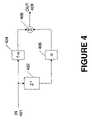
- FIG. 4is an illustration of a first order interpolation filter in accordance with an embodiment of the present invention.
- the present value, IN 401of the signal to be interpolated (e.g., voltage V 0 _RAW) is multiplied by a coefficient 1- ⁇ and then passed to summer 408 .
- the input signalis also passed through digital delay block 402 to generate a signal which represents the past sample of the signal IN 401 (e.g., VN- 1 ).
- This past sample of the input signalis then multiplied by a coefficient ⁇ in block 406 before being summed at block 408 with the signal from block 404 .
- the interpolation filter output signal, OUT 409is the output of summer block 408 and should approximate the output of the signal at the desired sample time.
- ⁇is substantially equivalent to the desired number of sample (e.g., multiplexer samples) delays of the sampler divided by the total number of elements being sampled by the sampler. For instance, in the embodiment of FIG. 2 six variables are being sampled. To correct for the phase introduced by non-simultaneous sampling, the value of the voltage (V 0 ) need be computed at the sampling point of the current (I 0 ), which is one sample back, as illustrated in FIG. 13 . Thus, the desire is to go one sample back of the multiplexer and since the total number of variables being sampled is 6, the coefficient ⁇ is approximately 1 ⁇ 6 for this one-sample delay interpolation.
- the best value of amay deviate slightly from 1 ⁇ 6 as a function of the input frequency, phase delays caused by hardware components in the path of the signals to be converted, and the ADC sample frequency.
- the interpolatorworks well when the waveform's sample frequency is high compared to its input frequency. As the input frequency approaches the sample rate, the magnitude and delay of the interpolator output both deviate from their nominal values (e.g., values at 50 Hz or 60 Hz). In the 50 Hz to 60 Hz region, the phase error of this interpolation filter is less than 0.0008 degrees and the magnitude error is less than 0.06% for a 2.5 KHz multiplexer sampling frequency. For two-sample delay interpolation, a may be set to 2/6. In this configuration, the phase error is less than 0.0006 degrees and the magnitude error is less than 0.1% at the 50 Hz to 60 Hz region.
- interpolatorsmay be used. This may be accomplished by simply adding successive delay states and coefficients to the circuit of FIG. 4 . For instance, a second order simply requires passing the output of block 402 through a second delay block and multiplying the output of the second delay by a second coefficient before summing at junction 408 . Of course, the coefficients in blocks 404 and 406 may need to be adjusted appropriately.
- FIG. 5is an illustration of a first order all-pass filter, in accordance with an embodiment of the present invention.
- Summer 502generates an error, using negative feedback, between the input signal, IN 501 , and the output of block 506 , which is the feedback signal.
- Gain block 506receives its input from block 504 , which is a digital delay block.
- Block 504 and gain block 508receive their inputs from the output of summing block 502 .
- the outputs of block 508 and block 504are summed in block 510 to generate the output signal, OUT 511 .
- This filter mechanizationproduces a constant amplitude response at all frequencies in embodiments where K 1 (block 506 ) is equal to K 2 (block 508 ).
- the all-pass filtermay be designed with a delay of 1 ⁇ 6 or 7/6 of the waveform sample rate.
- the later frequencymay provide better performance for high frequency harmonics of the input.
- the resulting voltage samplewould be multiplied by the current sample before the most recent one.
- delays of (n+1 ⁇ 6)Tmay be chosen, where 1/T is the waveform sample rate and n is the number of multiplexer cycles.
- the delay value of the all-pass filtermay be perturbed slightly to compensate for minor phase shifts occurring elsewhere in the system (e.g., watthour meter).
- K 1 and K 2will depend on the type of transformation used to implement the desired all-pass filter and any desired additional phase adjustments.
- K 1 and K 2will depend on the type of transformation used to implement the desired all-pass filter and any desired additional phase adjustments.
- first order all-pass filteris described herein, the present invention is not so limited to such implementation. Higher order filters may be used depending on application and accuracy requirements.
- FIG. 6is general schematic diagram illustrating an embodiment of the present invention for a three-phase electrical system.
- block 600may represent an Integrated Circuit device with only portions relevant to the present invention shown.
- the three phases of current and voltage: IA and VA; IB and VB; and IC and VC,are provided as inputs to MUX 200 via signal paths 641 through 646 .
- MUX 200uses clock from signal path 231 , MUX 200 generates a single output signal which it provides to A to D Converter block 602 via path 601 .
- a to D Converter block 602uses Delta-Sigma (also known as Sigma-Delta) conversion methods for generating a one-bit digital output stream at path 603 .
- Delta-Sigma converter block 602uses a high precision voltage source, VREF 607 , for power. Voltage VREF is generated by bandgap device 606 which receives a bias voltage from pin RBIAS.
- the 1-bit digital output stream of the delta-sigma converterfeeds into a decimation filter of the Finite Impulse Response type, FIR 604 .
- the decimation filterconverts the 1-bit stream input data to an N-bits digital output data.
- MUX 200 , A/D converter 602 , and FIR 604run on clock cycles originating from PLL 612 .
- the complete A to D converter processcomprises both the delta-sigma converter block 602 and the FIR block 604 . An embodiment of this converter process is discussed in more detail using FIG. 7 .
- the system clockis generated in Phase Lock Loop (PLL) 612 .
- PLL 612receives input reference clock either from Oscillator 614 or from an external source via pin CKIN and path 615 .
- the phase lock loop, 612generates the clock CKADC at output 232 using a type of voltage controlled oscillator.
- PLL 612also receives feedback from its output clock CKADC divided by a predetermined constant in block ADC DIV 610 .
- the dividerreduces the feedback frequency back to the input reference frequency (e.g., OSC 614 ).
- the PLL feedback signalis labeled CKREF in path 611 .
- ADC clock signal CKADCis an “ADC DIV” multiple of the reference oscillator clock.
- Multiplexer clock 231depends on the conversion time of the ADC. Therefore, the converter clock CKADC 232 must be scaled to generate the MUX clock, 231 .
- MUX clock 231must be less than or equal to the converter clock frequency, CKADC, divide by the number of signals being converted (i.e., 6) and divide by the number of taps in the decimation filter, FIR 604 .
- MUX DIVdivides the clock CKREF to generate the MUX clock signal 231 .
- “MUX DIV”should have a value approximately equal to the number of signals being converted (i.e., 6), multiplied by the number of taps in FIR 604 , and divided by the value of “ADC DIV”.
- FIG. 7is an illustration of a multi-bit delta-sigma A to D conversion process abstracted from FIG. 6 .
- Block 700represents the entire delta sigma ADC.
- This implementation of a delta-sigma ADCcomprises delta-sigma modulator block 702 and Sinc 3 decimator filter block 704 .
- ADC input 601 and ADC output 605represent the same signals in FIG. 6 .
- the delta-sigma modulatormay be of any desired order or type depending on the accuracy requirements, stability requirements, and other factors like space and power.
- Delta-Sigma modulator 702uses power from a precision voltage source, such as a bandgap device, to power its conversion circuits.
- the modulator and the decimatoruse the same clock signal CKADC 232 .
- the conversion clock of a delta-sigma modulatorwill depend on loop stability of the chosen delta-sigma configuration. Thus, a user's ability to set the conversion time is limited mostly by stability considerations for any given delta-sigma configuration.
- the various clock frequencies in this embodimentmay be as follows.
- Each of the IA, VA . . . VC waveformsare sampled at 2.520 KHz. This is also the system sample rate and is the value used in calculating the z ⁇ 1 terms in FIGS. 8 , 9 , and 11 .
- ADC Sinc 3 filterhas 288 taps.
- each of the six ADC conversionsmay be allocated 300 conversion clocks (the extra 12 clocks are used for ADC initialization). Assuming that 1 ⁇ 2 conversion time is needed for offset correction in the bandgap reference. Then there should be enough time for 6.5 ADC conversion cycles during each MUX cycle. Therefore, the ADC clock frequency is 4.91 MHz.
- the time between ADC samplesis 2/13 of the waveform sample rate. This is the value that should be compensated in the correction filter.
- the ADC DIV 610 ratiois 150, and the MUX DIV 608 ratio is 13.
- Compute engine 620After processing, output 605 of the ADC process (blocks 602 and 604 ) is stored in shared memory 624 .
- Compute engine 620obtains the converted signals from shared memory 624 , and depending on the desired power equation selected (see FIG. 12 ), computes the phase delay compensation and power values.
- Compute Engine 620is a digital microcomputer running at clock frequency CKCE 617 .
- Clock CKCEis generated from CKADC by dividing the later by CE DIV 616 .
- CKCEis the same frequency as the MUX frequency 231 .
- Compute Engine 620may be programmable via port DIO and bus 627 .
- Compute Engine's program memoryis located in block 626 and its RAM memory is located in block 622 .
- Block 600receives power from regulator VOLT REG 628 .
- Regulator 628regulates power from the input source V 3 P 3 D (3.3 Volts source) to digital components in device 600 .
- Regulator 628may also receive battery input VBAT for backup in case of power failure.
- Voltage pin V 3 P 3 Ais the voltage source for powering analog components in device 600 .
- pins V 3 P 3 A and V 3 P 3 Dmay be connected externally to a single power source.
- Pins GNDA and GNDDare analog and digital grounds respectively. Performance of device 600 may be monitored in real-time via pin labeled RTM.
- compute engine 620includes algorithms for compensating for DC offset in the converted signal, for calibrating the current and voltage signals, compensation for phase delay caused by non-simultaneous sampling, and for power computation based on the desired equation.
- Device 600may be fully programmable.
- MUX 200 and the clock signalsmay be programmed depending in the desired power equation.
- FIG. 8is an illustration of a compensation scheme in accordance with an embodiment of the present invention.
- the signalsare compensated for any DC (steady state) offset introduced by the A/D converter and any other pre-process involved in signal conversion.
- the compute enginesubsequently applies calibration compensation in blocks 811 – 816 .
- the voltage signalsi.e., in this instance the later sampled signal of each phase
- Each delay in the current path, blocks 831 – 833compensates for the extra cycle delay in the all-pass networks.
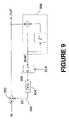
- FIG. 9One embodiment of offset compensation is shown in FIG. 9 .
- the circuit shown in FIG. 9behaves like a high-pass filter thus rejecting any DC offsets from the input signal.
- DC offset 903is computed and subtracted from the input signal, IN, in block 902 to generate the output signal, OUT.
- Block 908represents a digital integrator operating on the output signal.
- the output of block 908 , SUMis stored in register 906 .
- Output of register 906is multiplied by a gain “DCG” in block 904 to generate DC offset signal 903 .
- FIG. 12lists the six power equations that may be implemented in the compute engine. These power equations are implemented in FIG. 10 . Note that these are standard power equations and are only included herein for convenience.
- blocks 1001 and 1002represent all-pass filters with delays set to 17/13 for equations EQU 3 through EQU 5. This is because the current (I) of the next phase is sampled two ADC conversion times later than the current of the previous phase. For instance, I 1 is sampled two conversion cycles after 10 is sampled. Therefore, I 1 must be corrected to the sample time of I 0 (i.e., two samples prior) if power is to be computed accurately. Note that the transfer functions in blocks 1001 and 1002 should be zero for equations EQU 0 through EQU 2.
- the coefficients [K 0 , K 1 , K 2 ] of the desired equationare applied to generate power elements WO, W 1 , and W 2 .
- Each coefficientmay have a value of 0, 1 ⁇ 2, or 1.
- the coefficientsshould be [1,0,0] because only power from one phase is desired.
- the coefficient for equation EQU 2should be [1,1,1] because the powers from all three phases are summed together.
- VAR 0 –VAR 2blocks 1003 through 1005 applies a 90 degrees phase shift to each voltage signal before multiplying by the current to calculate power.
- An embodiment of a 90-degree phase shifter in accordance with an embodiment of the present inventionis illustrated in FIG. 11 .
- An optimum value for the variable VAR_SCALEshould be greater than 3000/FREQ/KVAR; where FREQ is the electrical system frequency, i.e., 50 Hz or 60 Hz.
- the value of 48.0134 u(i.e., 48.0134 ⁇ 10 6 ) shown for KVAR gives approximately 0.03% unity gain error between 50 Hz and 60 Hz at a MUX sampling frequency (also system clock) of 2.5 KHz.
- the value for KVARshould be 48.0279 u at 60 Hz and 48.0001 u at 50 Hz.
- the optimum value of KVARis weakly dependent on system clock frequency. For instance, the optimum value of KVAR at clock frequency of 5 KHz is 47.95599 u, which is a shift of 0.12% from the value shown for 2.5 KHz. It should be noted that the angular error is zero and is independent of the value of KVAR.
- summer 1020integrates all the power over time to generate the total power consumption.
Landscapes
- Engineering & Computer Science (AREA)
- Power Engineering (AREA)
- Physics & Mathematics (AREA)
- General Physics & Mathematics (AREA)
- Analogue/Digital Conversion (AREA)
Abstract
Description
Claims (17)
Priority Applications (1)
| Application Number | Priority Date | Filing Date | Title |
|---|---|---|---|
| US11/084,713US7102556B2 (en) | 2002-08-19 | 2005-03-18 | Method and apparatus for obtaining power computation parameters |
Applications Claiming Priority (3)
| Application Number | Priority Date | Filing Date | Title |
|---|---|---|---|
| US40455402P | 2002-08-19 | 2002-08-19 | |
| US10/637,969US6943714B2 (en) | 2002-08-19 | 2003-08-07 | Method and apparatus of obtaining power computation parameters |
| US11/084,713US7102556B2 (en) | 2002-08-19 | 2005-03-18 | Method and apparatus for obtaining power computation parameters |
Related Parent Applications (1)
| Application Number | Title | Priority Date | Filing Date |
|---|---|---|---|
| US10/637,969ContinuationUS6943714B2 (en) | 2002-08-19 | 2003-08-07 | Method and apparatus of obtaining power computation parameters |
Publications (2)
| Publication Number | Publication Date |
|---|---|
| US20050225469A1 US20050225469A1 (en) | 2005-10-13 |
| US7102556B2true US7102556B2 (en) | 2006-09-05 |
Family
ID=31888376
Family Applications (2)
| Application Number | Title | Priority Date | Filing Date |
|---|---|---|---|
| US10/637,969Expired - LifetimeUS6943714B2 (en) | 2002-08-19 | 2003-08-07 | Method and apparatus of obtaining power computation parameters |
| US11/084,713Expired - LifetimeUS7102556B2 (en) | 2002-08-19 | 2005-03-18 | Method and apparatus for obtaining power computation parameters |
Family Applications Before (1)
| Application Number | Title | Priority Date | Filing Date |
|---|---|---|---|
| US10/637,969Expired - LifetimeUS6943714B2 (en) | 2002-08-19 | 2003-08-07 | Method and apparatus of obtaining power computation parameters |
Country Status (7)
| Country | Link |
|---|---|
| US (2) | US6943714B2 (en) |
| EP (1) | EP1540357A2 (en) |
| JP (1) | JP2005536722A (en) |
| CN (1) | CN1682119A (en) |
| AU (1) | AU2003265492A1 (en) |
| WO (1) | WO2004017079A2 (en) |
| ZA (1) | ZA200501459B (en) |
Cited By (60)
| Publication number | Priority date | Publication date | Assignee | Title |
|---|---|---|---|---|
| US20080316752A1 (en)* | 2006-12-12 | 2008-12-25 | David Richard Kostuch | Clarifying filter |
| US20090024266A1 (en)* | 2007-07-17 | 2009-01-22 | Bertness Kevin I | Battery tester for electric vehicle |
| US20100013489A1 (en)* | 1999-11-01 | 2010-01-21 | Vonderhaar J David | Electronic battery tester |
| US20110218747A1 (en)* | 2010-03-03 | 2011-09-08 | Bertness Kevin I | Monitor for front terminal batteries |
| US8164343B2 (en) | 2003-09-05 | 2012-04-24 | Midtronics, Inc. | Method and apparatus for measuring a parameter of a vehicle electrical system |
| US8198900B2 (en) | 1996-07-29 | 2012-06-12 | Midtronics, Inc. | Automotive battery charging system tester |
| US8203345B2 (en) | 2007-12-06 | 2012-06-19 | Midtronics, Inc. | Storage battery and battery tester |
| US8237448B2 (en) | 2000-03-27 | 2012-08-07 | Midtronics, Inc. | Battery testers with secondary functionality |
| US8344685B2 (en) | 2004-08-20 | 2013-01-01 | Midtronics, Inc. | System for automatically gathering battery information |
| US8436619B2 (en) | 2004-08-20 | 2013-05-07 | Midtronics, Inc. | Integrated tag reader and environment sensor |
| US8442877B2 (en) | 2004-08-20 | 2013-05-14 | Midtronics, Inc. | Simplification of inventory management |
| US8478550B2 (en) | 2010-07-23 | 2013-07-02 | Caterpillar Inc. | Generator set calibration controller |
| US8493022B2 (en) | 1997-11-03 | 2013-07-23 | Midtronics, Inc. | Automotive vehicle electrical system diagnostic device |
| US8513949B2 (en) | 2000-03-27 | 2013-08-20 | Midtronics, Inc. | Electronic battery tester or charger with databus connection |
| US8674711B2 (en) | 2003-09-05 | 2014-03-18 | Midtronics, Inc. | Method and apparatus for measuring a parameter of a vehicle electrical system |
| US8674654B2 (en) | 1997-11-03 | 2014-03-18 | Midtronics, Inc. | In-vehicle battery monitor |
| US8738309B2 (en) | 2010-09-30 | 2014-05-27 | Midtronics, Inc. | Battery pack maintenance for electric vehicles |
| US8872517B2 (en) | 1996-07-29 | 2014-10-28 | Midtronics, Inc. | Electronic battery tester with battery age input |
| US8872516B2 (en) | 2000-03-27 | 2014-10-28 | Midtronics, Inc. | Electronic battery tester mounted in a vehicle |
| US8942942B2 (en) | 2010-07-23 | 2015-01-27 | Caterpillar Inc. | Generator set calibration controller |
| US8958998B2 (en) | 1997-11-03 | 2015-02-17 | Midtronics, Inc. | Electronic battery tester with network communication |
| US9018958B2 (en) | 2003-09-05 | 2015-04-28 | Midtronics, Inc. | Method and apparatus for measuring a parameter of a vehicle electrical system |
| US9201120B2 (en) | 2010-08-12 | 2015-12-01 | Midtronics, Inc. | Electronic battery tester for testing storage battery |
| US9229062B2 (en) | 2010-05-27 | 2016-01-05 | Midtronics, Inc. | Electronic storage battery diagnostic system |
| US9244100B2 (en) | 2013-03-15 | 2016-01-26 | Midtronics, Inc. | Current clamp with jaw closure detection |
| US9255955B2 (en) | 2003-09-05 | 2016-02-09 | Midtronics, Inc. | Method and apparatus for measuring a parameter of a vehicle electrical system |
| US9274157B2 (en) | 2007-07-17 | 2016-03-01 | Midtronics, Inc. | Battery tester for electric vehicle |
| US9312575B2 (en) | 2013-05-16 | 2016-04-12 | Midtronics, Inc. | Battery testing system and method |
| US20160187944A1 (en)* | 2014-12-26 | 2016-06-30 | Intel Corporation | Dynamic hierarchical performance balancing of computational resources |
| US9419311B2 (en) | 2010-06-18 | 2016-08-16 | Midtronics, Inc. | Battery maintenance device with thermal buffer |
| US20160282391A1 (en)* | 2015-03-26 | 2016-09-29 | Microchip Technology Incorporated | System and method for ripple-free ac power determination |
| US9496720B2 (en) | 2004-08-20 | 2016-11-15 | Midtronics, Inc. | System for automatically gathering battery information |
| US9588185B2 (en) | 2010-02-25 | 2017-03-07 | Keith S. Champlin | Method and apparatus for detecting cell deterioration in an electrochemical cell or battery |
| US20170187385A1 (en)* | 2015-12-29 | 2017-06-29 | Schweitzer Engineering Laboratories, Inc. | Supervision of Input Signal Channels |
| US9851411B2 (en) | 2012-06-28 | 2017-12-26 | Keith S. Champlin | Suppressing HF cable oscillations during dynamic measurements of cells and batteries |
| US9923289B2 (en) | 2014-01-16 | 2018-03-20 | Midtronics, Inc. | Battery clamp with endoskeleton design |
| US9966676B2 (en) | 2015-09-28 | 2018-05-08 | Midtronics, Inc. | Kelvin connector adapter for storage battery |
| US10046649B2 (en) | 2012-06-28 | 2018-08-14 | Midtronics, Inc. | Hybrid and electric vehicle battery pack maintenance device |
| US10101786B2 (en) | 2014-12-22 | 2018-10-16 | Intel Corporation | Holistic global performance and power management |
| US10222397B2 (en) | 2014-09-26 | 2019-03-05 | Midtronics, Inc. | Cable connector for electronic battery tester |
| US10317468B2 (en) | 2015-01-26 | 2019-06-11 | Midtronics, Inc. | Alternator tester |
| US10429449B2 (en) | 2011-11-10 | 2019-10-01 | Midtronics, Inc. | Battery pack tester |
| US10473555B2 (en) | 2014-07-14 | 2019-11-12 | Midtronics, Inc. | Automotive maintenance system |
| US10608353B2 (en) | 2016-06-28 | 2020-03-31 | Midtronics, Inc. | Battery clamp |
| US10843574B2 (en) | 2013-12-12 | 2020-11-24 | Midtronics, Inc. | Calibration and programming of in-vehicle battery sensors |
| US11054480B2 (en) | 2016-10-25 | 2021-07-06 | Midtronics, Inc. | Electrical load for electronic battery tester and electronic battery tester including such electrical load |
| US11325479B2 (en) | 2012-06-28 | 2022-05-10 | Midtronics, Inc. | Hybrid and electric vehicle battery maintenance device |
| US11474153B2 (en) | 2019-11-12 | 2022-10-18 | Midtronics, Inc. | Battery pack maintenance system |
| US11486930B2 (en) | 2020-01-23 | 2022-11-01 | Midtronics, Inc. | Electronic battery tester with battery clamp storage holsters |
| US11513160B2 (en) | 2018-11-29 | 2022-11-29 | Midtronics, Inc. | Vehicle battery maintenance device |
| US11545839B2 (en) | 2019-11-05 | 2023-01-03 | Midtronics, Inc. | System for charging a series of connected batteries |
| US11566972B2 (en) | 2019-07-31 | 2023-01-31 | Midtronics, Inc. | Tire tread gauge using visual indicator |
| US11650259B2 (en) | 2010-06-03 | 2023-05-16 | Midtronics, Inc. | Battery pack maintenance for electric vehicle |
| US11668779B2 (en) | 2019-11-11 | 2023-06-06 | Midtronics, Inc. | Hybrid and electric vehicle battery pack maintenance device |
| US11740294B2 (en) | 2010-06-03 | 2023-08-29 | Midtronics, Inc. | High use battery pack maintenance |
| US11973202B2 (en) | 2019-12-31 | 2024-04-30 | Midtronics, Inc. | Intelligent module interface for battery maintenance device |
| US12237482B2 (en) | 2019-12-31 | 2025-02-25 | Midtronics, Inc. | Intelligent module interface for battery maintenance device |
| US12320857B2 (en) | 2016-10-25 | 2025-06-03 | Midtronics, Inc. | Electrical load for electronic battery tester and electronic battery tester including such electrical load |
| US12330513B2 (en) | 2022-02-14 | 2025-06-17 | Midtronics, Inc. | Battery maintenance device with high voltage connector |
| US12392833B2 (en) | 2022-05-09 | 2025-08-19 | Midtronics, Inc. | Electronic battery tester |
Families Citing this family (38)
| Publication number | Priority date | Publication date | Assignee | Title |
|---|---|---|---|---|
| AU2002351313A1 (en)* | 2001-12-11 | 2003-07-09 | Thomson Licensing S.A. | Multiplexed analog-to-digital converter arrangement |
| US6922164B1 (en)* | 2004-03-31 | 2005-07-26 | Silicon Labs Cp. Inc. | SAR analog-to-digital converter with abort function |
| JP3950165B2 (en)* | 2004-05-19 | 2007-07-25 | 三菱電機株式会社 | Signal processing device |
| US6975951B1 (en)* | 2004-06-10 | 2005-12-13 | Raton Corporation | Meter apparatus and method for phase angle compensation employing linear interpolation of digital signals |
| US20060068897A1 (en)* | 2004-09-29 | 2006-03-30 | Sanford Kirk E | Purchase of slot vouchers with electronic funds (improved method and apparatus) |
| US7053804B1 (en)* | 2004-11-18 | 2006-05-30 | Analog Devices, Inc. | Phase-error reduction methods and controllers for time-interleaved analog-to-digital systems |
| US20060227910A1 (en)* | 2005-03-11 | 2006-10-12 | Nangavalli Ramasubramanian | Receiver DC offset correction |
| DE102007003010B4 (en)* | 2006-01-31 | 2017-02-09 | Sew-Eurodrive Gmbh & Co Kg | Plant, device and method |
| US7411533B2 (en)* | 2006-10-05 | 2008-08-12 | Intel Corporation | ADC for simultaneous multiple analog inputs |
| US7589516B2 (en) | 2007-01-05 | 2009-09-15 | Texas Instruments Incorporated | Poly-phase electric energy meter |
| DE102007001221B4 (en)* | 2007-01-05 | 2011-09-22 | Texas Instruments Deutschland Gmbh | Polyphase electric energy meter |
| ITVA20070011A1 (en)* | 2007-01-17 | 2008-07-18 | St Microelectronics Srl | METHOD AND ESTIMATION DEVICE OF THE VALUES OF TWO CIRCULATING CURRENTS IN THE SAME INSTANT IN THEIR PHASES OF A POLYPHASE LOAD PILOTED IN SWM MODE |
| ITVA20070008A1 (en)* | 2007-01-17 | 2008-07-18 | St Microelectronics Srl | METHOD AND RELATIVE DEVICE TO ESTIMATE VALUES ASSUMED IN A CERTAIN INSTANT FROM A CIRCULATING CURRENT IN A WINDING OF A POLIFASE ELECTRIC LOAD |
| DE102007021079A1 (en)* | 2007-05-03 | 2008-11-13 | Voith Patent Gmbh | Method for determining work / performance |
| CN101339210B (en)* | 2007-07-06 | 2011-07-06 | 西门子电力自动化有限公司 | Method and device for correcting phase error in power grid measurement and control equipment |
| US8165835B1 (en) | 2007-10-26 | 2012-04-24 | Cirrus Logic, Inc. | Complex wavelet filter based power measurement and calibration system |
| US7710299B2 (en)* | 2007-11-01 | 2010-05-04 | Conexant Systems, Inc. | System and method providing channel multiplexing for analog-to-digital conversion |
| US7746057B2 (en)* | 2008-03-28 | 2010-06-29 | Cirrus Logic, Inc. | Power meter having complex quadrature output current and voltage filters |
| TWI448084B (en)* | 2009-02-13 | 2014-08-01 | Silego Technology Inc | An integrated circuit frequency generator |
| KR101153504B1 (en)* | 2010-09-30 | 2012-06-12 | 한국전력공사 | Electronic watt-hour meter managing multiple input signal and method of calculating watt-hour |
| US9157940B2 (en)* | 2011-02-09 | 2015-10-13 | Smart Energy Instruments, Inc. | Power measurement device |
| US9194897B2 (en)* | 2011-03-10 | 2015-11-24 | Samsung Electro-Mechanics Co., Ltd. | Electronic watt-hour meter and electronic watt-hour measuring method |
| CN102890189A (en)* | 2011-07-21 | 2013-01-23 | 中兴通讯股份有限公司 | Electric quantity automatic statistical method and system for base station equipment |
| US9217766B2 (en)* | 2011-08-17 | 2015-12-22 | Analog Devices, Inc. | Apparatus and method for measuring active/reactive powers |
| KR101234879B1 (en)* | 2011-09-27 | 2013-02-19 | 한국전력공사 | Apparatus and method for power computation |
| KR101234944B1 (en)* | 2011-09-29 | 2013-02-19 | 삼성전기주식회사 | Apparatus and method for power computation |
| US9081043B2 (en)* | 2012-02-10 | 2015-07-14 | Sharp Laboratories Of America, Inc. | System and method for calculating power using contactless voltage waveform shape sensor |
| CN103777069B (en)* | 2012-10-26 | 2016-08-10 | 神讯电脑(昆山)有限公司 | Multi-group power supply power measurement system and its operation method |
| CN103063910B (en)* | 2012-12-28 | 2015-01-14 | 上海贝岭股份有限公司 | Inter-phase crosstalk compensation method for measurement of polyphase power of chip |
| US10372842B2 (en)* | 2013-03-14 | 2019-08-06 | Xerox Corporation | Method and device for calibrating and updating a power model |
| JP2015129657A (en)* | 2014-01-07 | 2015-07-16 | 横河電機株式会社 | measuring device |
| CN104360166B (en)* | 2014-12-02 | 2020-01-07 | 思澜科技(成都)有限公司 | Digital demodulation system phase error elimination method for bioimpedance measurement |
| EP3272083A4 (en)* | 2015-05-27 | 2018-12-05 | Hewlett-Packard Development Company, L.P. | Recovering independent waveforms from input bitstream data |
| JP6589836B2 (en)* | 2016-11-25 | 2019-10-16 | 株式会社デンソー | Motor control device and motor drive system |
| US11002771B2 (en)* | 2018-03-20 | 2021-05-11 | Renesas Electronics America Inc. | Predictive sample queueing for time-shared ADC in a multiphase PWM controller |
| US10911270B2 (en)* | 2018-10-03 | 2021-02-02 | Maxim Integrated Products, Inc. | Systems and methods for on-chip filtering |
| CN113848380B (en)* | 2021-10-22 | 2023-10-20 | 深圳市兆驰数码科技股份有限公司 | Power detection circuit and method, and direct current and phase detection system and method |
| TWI831150B (en) | 2022-03-17 | 2024-02-01 | 瑞昱半導體股份有限公司 | Sigma delta modulator |
Citations (13)
| Publication number | Priority date | Publication date | Assignee | Title |
|---|---|---|---|---|
| GB1575289A (en) | 1977-05-09 | 1980-09-17 | Heliowatt Werke | Compensating for time errors in measuring devices employing analog-stochastic converters |
| GB1575148A (en) | 1976-07-07 | 1980-09-17 | Heliowatt Werke | Electrical energy meters |
| US4672555A (en) | 1984-10-18 | 1987-06-09 | Massachusetts Institute Of Technology | Digital ac monitor |
| EP0591942A1 (en) | 1992-10-08 | 1994-04-13 | Gossen- Metrawatt GmbH | Electronic device for measuring such variables as active and reactive power and power factor |
| US5544089A (en) | 1992-02-21 | 1996-08-06 | Abb Power T&D Company Inc. | Programmable electrical energy meter using multiplexed analog-to-digital converters |
| US5561425A (en)* | 1992-12-16 | 1996-10-01 | U.S. Philips Corporation | Multiplexed delta-sigma analog-to-digital converter |
| US5870047A (en)* | 1997-07-07 | 1999-02-09 | Sicom, Inc. | Signal converter using multiple data streams and method therefor |
| US6058354A (en) | 1997-08-25 | 2000-05-02 | Electrowatt Technology Innovation Ag | Electricity meter to measure electrical physical magnitudes which are parameters or functions of measured voltages and/or currents |
| US6239589B1 (en)* | 1996-09-25 | 2001-05-29 | Siemens Aktiengesellschaft | Method and device for compensating for angle errors when measuring electrical power |
| US6341135B1 (en) | 1998-02-26 | 2002-01-22 | 3Com Corporation | Low power buffer system for network communications |
| US6373415B1 (en)* | 1999-09-24 | 2002-04-16 | Cirrus Logic, Inc. | Digital phase compensation methods and systems for a dual-channel analog-to-digital converter |
| US6466615B1 (en)* | 1999-12-30 | 2002-10-15 | Intel Corporation | Delay locked loop based circuit for data communication |
| US6759837B2 (en)* | 2001-08-28 | 2004-07-06 | Analog Devices, Inc. | Methods and apparatus for phase compensation in electronic energy meters |
Family Cites Families (5)
| Publication number | Priority date | Publication date | Assignee | Title |
|---|---|---|---|---|
| US6081215A (en)* | 1998-07-06 | 2000-06-27 | Motorola, Inc. | High speed interlaced analog interface |
| US6238589B1 (en) | 1998-08-21 | 2001-05-29 | International Business Machines Corporation | Methods for monitoring components in the TiW etching bath used in the fabrication of C4s |
| DE19842241A1 (en) | 1998-09-15 | 2000-04-06 | Siemens Metering Ag | Electricity meter and input module for an electricity meter |
| US6255973B1 (en)* | 1999-08-26 | 2001-07-03 | Analog Devices, Inc. | Address selection circuitry and method using single analog input line |
| US6522282B1 (en)* | 2001-11-07 | 2003-02-18 | Telefonaktiebolaget Lm Ericsson (Publ) | Estimation of timing offsets in parallel A/D converters |
- 2003
- 2003-08-07USUS10/637,969patent/US6943714B2/ennot_activeExpired - Lifetime
- 2003-08-19JPJP2004529118Apatent/JP2005536722A/enactivePending
- 2003-08-19EPEP03788633Apatent/EP1540357A2/ennot_activeWithdrawn
- 2003-08-19AUAU2003265492Apatent/AU2003265492A1/ennot_activeAbandoned
- 2003-08-19CNCN03821702.3Apatent/CN1682119A/enactivePending
- 2003-08-19WOPCT/US2003/025908patent/WO2004017079A2/enactiveApplication Filing
- 2005
- 2005-02-18ZAZA200501459Apatent/ZA200501459B/enunknown
- 2005-03-18USUS11/084,713patent/US7102556B2/ennot_activeExpired - Lifetime
Patent Citations (13)
| Publication number | Priority date | Publication date | Assignee | Title |
|---|---|---|---|---|
| GB1575148A (en) | 1976-07-07 | 1980-09-17 | Heliowatt Werke | Electrical energy meters |
| GB1575289A (en) | 1977-05-09 | 1980-09-17 | Heliowatt Werke | Compensating for time errors in measuring devices employing analog-stochastic converters |
| US4672555A (en) | 1984-10-18 | 1987-06-09 | Massachusetts Institute Of Technology | Digital ac monitor |
| US5544089A (en) | 1992-02-21 | 1996-08-06 | Abb Power T&D Company Inc. | Programmable electrical energy meter using multiplexed analog-to-digital converters |
| EP0591942A1 (en) | 1992-10-08 | 1994-04-13 | Gossen- Metrawatt GmbH | Electronic device for measuring such variables as active and reactive power and power factor |
| US5561425A (en)* | 1992-12-16 | 1996-10-01 | U.S. Philips Corporation | Multiplexed delta-sigma analog-to-digital converter |
| US6239589B1 (en)* | 1996-09-25 | 2001-05-29 | Siemens Aktiengesellschaft | Method and device for compensating for angle errors when measuring electrical power |
| US5870047A (en)* | 1997-07-07 | 1999-02-09 | Sicom, Inc. | Signal converter using multiple data streams and method therefor |
| US6058354A (en) | 1997-08-25 | 2000-05-02 | Electrowatt Technology Innovation Ag | Electricity meter to measure electrical physical magnitudes which are parameters or functions of measured voltages and/or currents |
| US6341135B1 (en) | 1998-02-26 | 2002-01-22 | 3Com Corporation | Low power buffer system for network communications |
| US6373415B1 (en)* | 1999-09-24 | 2002-04-16 | Cirrus Logic, Inc. | Digital phase compensation methods and systems for a dual-channel analog-to-digital converter |
| US6466615B1 (en)* | 1999-12-30 | 2002-10-15 | Intel Corporation | Delay locked loop based circuit for data communication |
| US6759837B2 (en)* | 2001-08-28 | 2004-07-06 | Analog Devices, Inc. | Methods and apparatus for phase compensation in electronic energy meters |
Non-Patent Citations (3)
| Title |
|---|
| International Search Report by EPO dated Feb. 20, 2004. |
| XP 002269086, 1999, Iwansson et al., p. 160,164,186. |
| XP-002269086-Iwansson et al.: Measuring Current Voltage and Power 1999, Elsevier Science, Amsterdam, pp. 160-164, pp. 186, no month. |
Cited By (77)
| Publication number | Priority date | Publication date | Assignee | Title |
|---|---|---|---|---|
| US8198900B2 (en) | 1996-07-29 | 2012-06-12 | Midtronics, Inc. | Automotive battery charging system tester |
| US8872517B2 (en) | 1996-07-29 | 2014-10-28 | Midtronics, Inc. | Electronic battery tester with battery age input |
| US8493022B2 (en) | 1997-11-03 | 2013-07-23 | Midtronics, Inc. | Automotive vehicle electrical system diagnostic device |
| US8958998B2 (en) | 1997-11-03 | 2015-02-17 | Midtronics, Inc. | Electronic battery tester with network communication |
| US8674654B2 (en) | 1997-11-03 | 2014-03-18 | Midtronics, Inc. | In-vehicle battery monitor |
| US20100013489A1 (en)* | 1999-11-01 | 2010-01-21 | Vonderhaar J David | Electronic battery tester |
| US8754653B2 (en) | 1999-11-01 | 2014-06-17 | Midtronics, Inc. | Electronic battery tester |
| US9052366B2 (en) | 2000-03-27 | 2015-06-09 | Midtronics, Inc. | Battery testers with secondary functionality |
| US8237448B2 (en) | 2000-03-27 | 2012-08-07 | Midtronics, Inc. | Battery testers with secondary functionality |
| US8513949B2 (en) | 2000-03-27 | 2013-08-20 | Midtronics, Inc. | Electronic battery tester or charger with databus connection |
| US8872516B2 (en) | 2000-03-27 | 2014-10-28 | Midtronics, Inc. | Electronic battery tester mounted in a vehicle |
| US9018958B2 (en) | 2003-09-05 | 2015-04-28 | Midtronics, Inc. | Method and apparatus for measuring a parameter of a vehicle electrical system |
| US8164343B2 (en) | 2003-09-05 | 2012-04-24 | Midtronics, Inc. | Method and apparatus for measuring a parameter of a vehicle electrical system |
| US9255955B2 (en) | 2003-09-05 | 2016-02-09 | Midtronics, Inc. | Method and apparatus for measuring a parameter of a vehicle electrical system |
| US8674711B2 (en) | 2003-09-05 | 2014-03-18 | Midtronics, Inc. | Method and apparatus for measuring a parameter of a vehicle electrical system |
| US8344685B2 (en) | 2004-08-20 | 2013-01-01 | Midtronics, Inc. | System for automatically gathering battery information |
| US8963550B2 (en) | 2004-08-20 | 2015-02-24 | Midtronics, Inc. | System for automatically gathering battery information |
| US9496720B2 (en) | 2004-08-20 | 2016-11-15 | Midtronics, Inc. | System for automatically gathering battery information |
| US8704483B2 (en) | 2004-08-20 | 2014-04-22 | Midtronics, Inc. | System for automatically gathering battery information |
| US8436619B2 (en) | 2004-08-20 | 2013-05-07 | Midtronics, Inc. | Integrated tag reader and environment sensor |
| US8442877B2 (en) | 2004-08-20 | 2013-05-14 | Midtronics, Inc. | Simplification of inventory management |
| US20080316752A1 (en)* | 2006-12-12 | 2008-12-25 | David Richard Kostuch | Clarifying filter |
| US20090024266A1 (en)* | 2007-07-17 | 2009-01-22 | Bertness Kevin I | Battery tester for electric vehicle |
| US20130158782A1 (en)* | 2007-07-17 | 2013-06-20 | Midtronics, Inc. | Battery tester for electric vehicle |
| US9335362B2 (en)* | 2007-07-17 | 2016-05-10 | Midtronics, Inc. | Battery tester for electric vehicle |
| US8306690B2 (en)* | 2007-07-17 | 2012-11-06 | Midtronics, Inc. | Battery tester for electric vehicle |
| US9274157B2 (en) | 2007-07-17 | 2016-03-01 | Midtronics, Inc. | Battery tester for electric vehicle |
| US8203345B2 (en) | 2007-12-06 | 2012-06-19 | Midtronics, Inc. | Storage battery and battery tester |
| US9588185B2 (en) | 2010-02-25 | 2017-03-07 | Keith S. Champlin | Method and apparatus for detecting cell deterioration in an electrochemical cell or battery |
| US9425487B2 (en) | 2010-03-03 | 2016-08-23 | Midtronics, Inc. | Monitor for front terminal batteries |
| US20110218747A1 (en)* | 2010-03-03 | 2011-09-08 | Bertness Kevin I | Monitor for front terminal batteries |
| US9229062B2 (en) | 2010-05-27 | 2016-01-05 | Midtronics, Inc. | Electronic storage battery diagnostic system |
| US11650259B2 (en) | 2010-06-03 | 2023-05-16 | Midtronics, Inc. | Battery pack maintenance for electric vehicle |
| US12196813B2 (en) | 2010-06-03 | 2025-01-14 | Midtronics, Inc. | High use battery pack maintenance |
| US11740294B2 (en) | 2010-06-03 | 2023-08-29 | Midtronics, Inc. | High use battery pack maintenance |
| US9419311B2 (en) | 2010-06-18 | 2016-08-16 | Midtronics, Inc. | Battery maintenance device with thermal buffer |
| US8942942B2 (en) | 2010-07-23 | 2015-01-27 | Caterpillar Inc. | Generator set calibration controller |
| US8478550B2 (en) | 2010-07-23 | 2013-07-02 | Caterpillar Inc. | Generator set calibration controller |
| US9201120B2 (en) | 2010-08-12 | 2015-12-01 | Midtronics, Inc. | Electronic battery tester for testing storage battery |
| US8738309B2 (en) | 2010-09-30 | 2014-05-27 | Midtronics, Inc. | Battery pack maintenance for electric vehicles |
| US10429449B2 (en) | 2011-11-10 | 2019-10-01 | Midtronics, Inc. | Battery pack tester |
| US11926224B2 (en) | 2012-06-28 | 2024-03-12 | Midtronics, Inc. | Hybrid and electric vehicle battery pack maintenance device |
| US11325479B2 (en) | 2012-06-28 | 2022-05-10 | Midtronics, Inc. | Hybrid and electric vehicle battery maintenance device |
| US10046649B2 (en) | 2012-06-28 | 2018-08-14 | Midtronics, Inc. | Hybrid and electric vehicle battery pack maintenance device |
| US11548404B2 (en) | 2012-06-28 | 2023-01-10 | Midtronics, Inc. | Hybrid and electric vehicle battery pack maintenance device |
| US9851411B2 (en) | 2012-06-28 | 2017-12-26 | Keith S. Champlin | Suppressing HF cable oscillations during dynamic measurements of cells and batteries |
| US9244100B2 (en) | 2013-03-15 | 2016-01-26 | Midtronics, Inc. | Current clamp with jaw closure detection |
| US9312575B2 (en) | 2013-05-16 | 2016-04-12 | Midtronics, Inc. | Battery testing system and method |
| US10843574B2 (en) | 2013-12-12 | 2020-11-24 | Midtronics, Inc. | Calibration and programming of in-vehicle battery sensors |
| US9923289B2 (en) | 2014-01-16 | 2018-03-20 | Midtronics, Inc. | Battery clamp with endoskeleton design |
| US10473555B2 (en) | 2014-07-14 | 2019-11-12 | Midtronics, Inc. | Automotive maintenance system |
| US10222397B2 (en) | 2014-09-26 | 2019-03-05 | Midtronics, Inc. | Cable connector for electronic battery tester |
| US10101786B2 (en) | 2014-12-22 | 2018-10-16 | Intel Corporation | Holistic global performance and power management |
| US11740673B2 (en) | 2014-12-22 | 2023-08-29 | Intel Corporation | Holistic global performance and power management |
| US10884471B2 (en) | 2014-12-22 | 2021-01-05 | Intel Corporation | Holistic global performance and power management |
| US12093104B1 (en) | 2014-12-22 | 2024-09-17 | Intel Corporation | Holistic global performance and power management |
| US10466754B2 (en)* | 2014-12-26 | 2019-11-05 | Intel Corporation | Dynamic hierarchical performance balancing of computational resources |
| US20160187944A1 (en)* | 2014-12-26 | 2016-06-30 | Intel Corporation | Dynamic hierarchical performance balancing of computational resources |
| US10317468B2 (en) | 2015-01-26 | 2019-06-11 | Midtronics, Inc. | Alternator tester |
| US20160282391A1 (en)* | 2015-03-26 | 2016-09-29 | Microchip Technology Incorporated | System and method for ripple-free ac power determination |
| US10197605B2 (en)* | 2015-03-26 | 2019-02-05 | Microchip Technology Incorporated | System and method for ripple-free AC power determination |
| US9966676B2 (en) | 2015-09-28 | 2018-05-08 | Midtronics, Inc. | Kelvin connector adapter for storage battery |
| US9843335B2 (en)* | 2015-12-29 | 2017-12-12 | Schweitzer Engineering Laboratories, Inc. | Supervision of input signal channels |
| US20170187385A1 (en)* | 2015-12-29 | 2017-06-29 | Schweitzer Engineering Laboratories, Inc. | Supervision of Input Signal Channels |
| US10608353B2 (en) | 2016-06-28 | 2020-03-31 | Midtronics, Inc. | Battery clamp |
| US12320857B2 (en) | 2016-10-25 | 2025-06-03 | Midtronics, Inc. | Electrical load for electronic battery tester and electronic battery tester including such electrical load |
| US11054480B2 (en) | 2016-10-25 | 2021-07-06 | Midtronics, Inc. | Electrical load for electronic battery tester and electronic battery tester including such electrical load |
| US11513160B2 (en) | 2018-11-29 | 2022-11-29 | Midtronics, Inc. | Vehicle battery maintenance device |
| US11566972B2 (en) | 2019-07-31 | 2023-01-31 | Midtronics, Inc. | Tire tread gauge using visual indicator |
| US11545839B2 (en) | 2019-11-05 | 2023-01-03 | Midtronics, Inc. | System for charging a series of connected batteries |
| US11668779B2 (en) | 2019-11-11 | 2023-06-06 | Midtronics, Inc. | Hybrid and electric vehicle battery pack maintenance device |
| US11474153B2 (en) | 2019-11-12 | 2022-10-18 | Midtronics, Inc. | Battery pack maintenance system |
| US11973202B2 (en) | 2019-12-31 | 2024-04-30 | Midtronics, Inc. | Intelligent module interface for battery maintenance device |
| US12237482B2 (en) | 2019-12-31 | 2025-02-25 | Midtronics, Inc. | Intelligent module interface for battery maintenance device |
| US11486930B2 (en) | 2020-01-23 | 2022-11-01 | Midtronics, Inc. | Electronic battery tester with battery clamp storage holsters |
| US12330513B2 (en) | 2022-02-14 | 2025-06-17 | Midtronics, Inc. | Battery maintenance device with high voltage connector |
| US12392833B2 (en) | 2022-05-09 | 2025-08-19 | Midtronics, Inc. | Electronic battery tester |
Also Published As
| Publication number | Publication date |
|---|---|
| US20040032357A1 (en) | 2004-02-19 |
| US6943714B2 (en) | 2005-09-13 |
| WO2004017079A3 (en) | 2004-04-29 |
| WO2004017079A2 (en) | 2004-02-26 |
| CN1682119A (en) | 2005-10-12 |
| US20050225469A1 (en) | 2005-10-13 |
| JP2005536722A (en) | 2005-12-02 |
| AU2003265492A1 (en) | 2004-03-03 |
| AU2003265492A8 (en) | 2004-03-03 |
| ZA200501459B (en) | 2005-09-07 |
| EP1540357A2 (en) | 2005-06-15 |
Similar Documents
| Publication | Publication Date | Title |
|---|---|---|
| US7102556B2 (en) | Method and apparatus for obtaining power computation parameters | |
| US10205460B2 (en) | Fractional-N frequency synthesizer and method thereof | |
| US5017860A (en) | Electronic meter digital phase compensation | |
| JP4727514B2 (en) | Electricity meter | |
| US6396313B1 (en) | Noise-shaped digital frequency synthesis | |
| EP0575071A2 (en) | A/D converter | |
| CN110244116A (en) | The metering circuit of direct current instantaneous power and its plesiochronous calculation method | |
| WO2023086268A1 (en) | Sampling rate converter with line frequency and phase locked loops for energy metering | |
| US11621624B2 (en) | Phase tracking in AC power systems using coherent sampling | |
| EP0815461B1 (en) | Timing generator with multiple coherent synchronized clocks | |
| US6373415B1 (en) | Digital phase compensation methods and systems for a dual-channel analog-to-digital converter | |
| JPH07105762B2 (en) | Analog-to-digital converter using decimation filter of sigma-delta converter and the same | |
| EP1605275B1 (en) | Electronic meter digital phase compensation | |
| JP4844882B2 (en) | Power measurement unit IC circuit | |
| WO2017143425A1 (en) | Methods and devices for time synchronized power measurement | |
| KR101153504B1 (en) | Electronic watt-hour meter managing multiple input signal and method of calculating watt-hour | |
| US7917797B2 (en) | Clock generation using a fractional phase detector | |
| US6304202B1 (en) | Delay correction system and method for a voltage channel in a sampled data measurement system | |
| JP2813508B2 (en) | Electronic watt-hour meter | |
| EP0377282B1 (en) | Electronic meter digital phase compensation | |
| US20120161750A1 (en) | Electronic watt-hour meter and method of calculating watt-hours | |
| JP2023093327A (en) | System and method for calibrating analog-to-digital converter using rational sampling frequency calibration digital-to-analog converter | |
| US7764758B2 (en) | Apparatus and/or method for variable data rate conversion | |
| EP1038380B1 (en) | Phase digitizer for radio communications | |
| JPH06207955A (en) | π / 2 phase shift circuit, and reactive energy meter and composite meter using the same |
Legal Events
| Date | Code | Title | Description |
|---|---|---|---|
| STCF | Information on status: patent grant | Free format text:PATENTED CASE | |
| FEPP | Fee payment procedure | Free format text:PAYOR NUMBER ASSIGNED (ORIGINAL EVENT CODE: ASPN); ENTITY STATUS OF PATENT OWNER: LARGE ENTITY | |
| AS | Assignment | Owner name:TERIDIAN SEMICONDUCTOR CORP.,CALIFORNIA Free format text:CHANGE OF NAME;ASSIGNOR:TDK SEMICONDUCTOR CORP.;REEL/FRAME:024079/0005 Effective date:20050623 | |
| REMI | Maintenance fee reminder mailed | ||
| FPAY | Fee payment | Year of fee payment:4 | |
| SULP | Surcharge for late payment | ||
| AS | Assignment | Owner name:MAXIM INTEGRATED PRODUCTS, INC.,CALIFORNIA Free format text:MERGER;ASSIGNOR:TERIDIAN SEMICONDUCTOR CORPORATION;REEL/FRAME:024474/0569 Effective date:20100409 Owner name:MAXIM INTEGRATED PRODUCTS, INC., CALIFORNIA Free format text:MERGER;ASSIGNOR:TERIDIAN SEMICONDUCTOR CORPORATION;REEL/FRAME:024474/0569 Effective date:20100409 | |
| AS | Assignment | Owner name:MAXIM INTEGRATED PRODUCTS, INC.,CALIFORNIA Free format text:CORRECTIVE ASSIGNMENT TO CORRECT THE ASSIGNOR ON THE NOTICE OF RECORDATION PREVIOUSLY RECORDED ON REEL 024474 FRAME 0569. ASSIGNOR(S) HEREBY CONFIRMS THE CORRECT ASSIGNOR IS TERIDIAN SEMICONDUCTOR HOLDINGS CORPORATION;ASSIGNOR:TERIDIAN SEMICONDUCTOR HOLDINGS CORPORATION;REEL/FRAME:024588/0146 Effective date:20100409 Owner name:MAXIM INTEGRATED PRODUCTS, INC., CALIFORNIA Free format text:CORRECTIVE ASSIGNMENT TO CORRECT THE ASSIGNOR ON THE NOTICE OF RECORDATION PREVIOUSLY RECORDED ON REEL 024474 FRAME 0569. ASSIGNOR(S) HEREBY CONFIRMS THE CORRECT ASSIGNOR IS TERIDIAN SEMICONDUCTOR HOLDINGS CORPORATION;ASSIGNOR:TERIDIAN SEMICONDUCTOR HOLDINGS CORPORATION;REEL/FRAME:024588/0146 Effective date:20100409 | |
| AS | Assignment | Owner name:TERIDIAN SEMICONDUCTOR HOLDINGS CORPORATION,CALIFO Free format text:CORRECTIVE ASSIGNMENT TO CORRECT THE ASSIGNOR AND ASSIGNEE PREVIOUSLY RECORDED ON REEL 024474 FRAME 0569. ASSIGNOR(S) HEREBY CONFIRMS THE ASSIGNOR IS TERIDIAN SEMICONDUCTOR CORPORATION AND ASSIGNEE IS TERIDIAN SEMICONDUCTOR HOLDINGS CORPORATION;ASSIGNOR:TERIDIAN SEMICONDUCTOR CORPORATION;REEL/FRAME:024588/0664 Effective date:20100409 Owner name:TERIDIAN SEMICONDUCTOR HOLDINGS CORPORATION, CALIF Free format text:CORRECTIVE ASSIGNMENT TO CORRECT THE ASSIGNOR AND ASSIGNEE PREVIOUSLY RECORDED ON REEL 024474 FRAME 0569. ASSIGNOR(S) HEREBY CONFIRMS THE ASSIGNOR IS TERIDIAN SEMICONDUCTOR CORPORATION AND ASSIGNEE IS TERIDIAN SEMICONDUCTOR HOLDINGS CORPORATION;ASSIGNOR:TERIDIAN SEMICONDUCTOR CORPORATION;REEL/FRAME:024588/0664 Effective date:20100409 | |
| AS | Assignment | Owner name:MAXIM INTEGRATED PRODUCTS, INC., CALIFORNIA Free format text:ASSIGNMENT OF ASSIGNORS INTEREST;ASSIGNOR:TERIDIAN SEMICONDUCTOR HOLDINGS CORPORATION;REEL/FRAME:024630/0640 Effective date:20100629 | |
| FPAY | Fee payment | Year of fee payment:8 | |
| AS | Assignment | Owner name:SILERGY CORP., UNITED KINGDOM Free format text:ASSIGNMENT OF ASSIGNORS INTEREST;ASSIGNOR:MAXIM INTEGRATED PRODUCTS, INC.;REEL/FRAME:038414/0417 Effective date:20151230 | |
| MAFP | Maintenance fee payment | Free format text:PAYMENT OF MAINTENANCE FEE, 12TH YEAR, LARGE ENTITY (ORIGINAL EVENT CODE: M1553) Year of fee payment:12 | |
| AS | Assignment | Owner name:SILERGY SEMICONDUCTOR (HONG KONG) LTD., HONG KONG Free format text:ASSIGNMENT OF ASSIGNORS INTEREST;ASSIGNOR:SILERGY CORP.;REEL/FRAME:054791/0134 Effective date:20201203 |