US7101330B2 - Proprioceptive/kinesthetic apparatus and method - Google Patents
Proprioceptive/kinesthetic apparatus and methodDownload PDFInfo
- Publication number
- US7101330B2 US7101330B2US10/397,419US39741903AUS7101330B2US 7101330 B2US7101330 B2US 7101330B2US 39741903 AUS39741903 AUS 39741903AUS 7101330 B2US7101330 B2US 7101330B2
- Authority
- US
- United States
- Prior art keywords
- support member
- protuberances
- exercise
- foot
- proprioceptive
- Prior art date
- Legal status (The legal status is an assumption and is not a legal conclusion. Google has not performed a legal analysis and makes no representation as to the accuracy of the status listed.)
- Expired - Lifetime, expires
Links
- 230000000272proprioceptive effectEffects0.000titleclaimsabstractdescription21
- 230000003155kinesthetic effectEffects0.000titleclaimsabstractdescription14
- 238000000034methodMethods0.000titleclaimsabstractdescription9
- 210000002683footAnatomy0.000claimsdescription22
- 230000002232neuromuscularEffects0.000claimsdescription12
- 210000000459calcaneusAnatomy0.000claimsdescription3
- 210000001872metatarsal boneAnatomy0.000claimsdescription2
- 230000033001locomotionEffects0.000description24
- 230000007246mechanismEffects0.000description20
- 210000003205muscleAnatomy0.000description15
- 230000009023proprioceptive sensationEffects0.000description8
- 239000000463materialSubstances0.000description7
- 210000001624hipAnatomy0.000description5
- 230000024159perception of rate of movementEffects0.000description5
- 208000027418Wounds and injuryDiseases0.000description4
- 210000003423ankleAnatomy0.000description4
- 210000000412mechanoreceptorAnatomy0.000description4
- 108091008704mechanoreceptorsProteins0.000description4
- 206010049816Muscle tightnessDiseases0.000description3
- 230000009471actionEffects0.000description3
- 210000003169central nervous systemAnatomy0.000description3
- 230000006378damageEffects0.000description3
- 208000014674injuryDiseases0.000description3
- 210000002414legAnatomy0.000description3
- 210000004699muscle spindleAnatomy0.000description3
- 108091008709muscle spindlesProteins0.000description3
- 239000011435rockSubstances0.000description3
- 230000035807sensationEffects0.000description3
- 230000001133accelerationEffects0.000description2
- 210000004556brainAnatomy0.000description2
- -1but not limited toSubstances0.000description2
- 229920001971elastomerPolymers0.000description2
- 239000000806elastomerSubstances0.000description2
- 239000000835fiberSubstances0.000description2
- 210000000474heelAnatomy0.000description2
- 210000003127kneeAnatomy0.000description2
- 239000007788liquidSubstances0.000description2
- 239000002184metalSubstances0.000description2
- 210000002346musculoskeletal systemAnatomy0.000description2
- 230000002093peripheral effectEffects0.000description2
- 230000001144postural effectEffects0.000description2
- 230000004044responseEffects0.000description2
- 210000001044sensory neuronAnatomy0.000description2
- 210000000278spinal cordAnatomy0.000description2
- 210000002435tendonAnatomy0.000description2
- XLYOFNOQVPJJNP-UHFFFAOYSA-NwaterSubstancesOXLYOFNOQVPJJNP-UHFFFAOYSA-N0.000description2
- 208000008035Back PainDiseases0.000description1
- 208000025940Back injuryDiseases0.000description1
- 208000018152Cerebral diseaseDiseases0.000description1
- 208000023803Hip injuryDiseases0.000description1
- 208000016593Knee injuryDiseases0.000description1
- 208000012902Nervous system diseaseDiseases0.000description1
- 208000025966Neurological diseaseDiseases0.000description1
- 208000003443UnconsciousnessDiseases0.000description1
- 210000003484anatomyAnatomy0.000description1
- 208000022542ankle injuryDiseases0.000description1
- 230000000454anti-cipatory effectEffects0.000description1
- 210000000617armAnatomy0.000description1
- 230000002490cerebral effectEffects0.000description1
- 230000009194climbingEffects0.000description1
- 230000006835compressionEffects0.000description1
- 238000007906compressionMethods0.000description1
- 210000002808connective tissueAnatomy0.000description1
- 238000010276constructionMethods0.000description1
- 230000000694effectsEffects0.000description1
- 230000002708enhancing effectEffects0.000description1
- 210000003811fingerAnatomy0.000description1
- 239000012530fluidSubstances0.000description1
- 230000006870functionEffects0.000description1
- 210000004247handAnatomy0.000description1
- 230000001771impaired effectEffects0.000description1
- 210000000281joint capsuleAnatomy0.000description1
- 210000003041ligamentAnatomy0.000description1
- 239000011159matrix materialSubstances0.000description1
- 238000012986modificationMethods0.000description1
- 230000004048modificationEffects0.000description1
- 230000003387muscularEffects0.000description1
- 210000001640nerve endingAnatomy0.000description1
- 210000004126nerve fiberAnatomy0.000description1
- 210000000056organAnatomy0.000description1
- 210000004197pelvisAnatomy0.000description1
- 210000000578peripheral nerveAnatomy0.000description1
- 230000008569processEffects0.000description1
- 230000001681protective effectEffects0.000description1
- 210000002265sensory receptor cellAnatomy0.000description1
- 108091008691sensory receptorsProteins0.000description1
- 102000027509sensory receptorsHuman genes0.000description1
- 210000002027skeletal muscleAnatomy0.000description1
- 210000004872soft tissueAnatomy0.000description1
- 230000000087stabilizing effectEffects0.000description1
- 238000005728strengtheningMethods0.000description1
- 239000013589supplementSubstances0.000description1
- 210000001519tissueAnatomy0.000description1
- 210000003371toeAnatomy0.000description1
Images


Classifications
- A—HUMAN NECESSITIES
- A43—FOOTWEAR
- A43B—CHARACTERISTIC FEATURES OF FOOTWEAR; PARTS OF FOOTWEAR
- A43B5/00—Footwear for sporting purposes
- A43B5/18—Attachable overshoes for sporting purposes
- A—HUMAN NECESSITIES
- A43—FOOTWEAR
- A43B—CHARACTERISTIC FEATURES OF FOOTWEAR; PARTS OF FOOTWEAR
- A43B13/00—Soles; Sole-and-heel integral units
- A43B13/14—Soles; Sole-and-heel integral units characterised by the constructive form
- A43B13/143—Soles; Sole-and-heel integral units characterised by the constructive form provided with wedged, concave or convex end portions, e.g. for improving roll-off of the foot
- A43B13/145—Convex portions, e.g. with a bump or projection, e.g. 'Masai' type shoes
- A—HUMAN NECESSITIES
- A43—FOOTWEAR
- A43B—CHARACTERISTIC FEATURES OF FOOTWEAR; PARTS OF FOOTWEAR
- A43B7/00—Footwear with health or hygienic arrangements
- A43B7/14—Footwear with health or hygienic arrangements with foot-supporting parts
- A43B7/1405—Footwear with health or hygienic arrangements with foot-supporting parts with pads or holes on one or more locations, or having an anatomical or curved form
- A43B7/1415—Footwear with health or hygienic arrangements with foot-supporting parts with pads or holes on one or more locations, or having an anatomical or curved form characterised by the location under the foot
- A43B7/144—Footwear with health or hygienic arrangements with foot-supporting parts with pads or holes on one or more locations, or having an anatomical or curved form characterised by the location under the foot situated under the heel, i.e. the calcaneus bone
- A—HUMAN NECESSITIES
- A43—FOOTWEAR
- A43B—CHARACTERISTIC FEATURES OF FOOTWEAR; PARTS OF FOOTWEAR
- A43B7/00—Footwear with health or hygienic arrangements
- A43B7/14—Footwear with health or hygienic arrangements with foot-supporting parts
- A43B7/1405—Footwear with health or hygienic arrangements with foot-supporting parts with pads or holes on one or more locations, or having an anatomical or curved form
- A43B7/1415—Footwear with health or hygienic arrangements with foot-supporting parts with pads or holes on one or more locations, or having an anatomical or curved form characterised by the location under the foot
- A43B7/1445—Footwear with health or hygienic arrangements with foot-supporting parts with pads or holes on one or more locations, or having an anatomical or curved form characterised by the location under the foot situated under the midfoot, i.e. the second, third or fourth metatarsal
- A—HUMAN NECESSITIES
- A63—SPORTS; GAMES; AMUSEMENTS
- A63B—APPARATUS FOR PHYSICAL TRAINING, GYMNASTICS, SWIMMING, CLIMBING, OR FENCING; BALL GAMES; TRAINING EQUIPMENT
- A63B21/00—Exercising apparatus for developing or strengthening the muscles or joints of the body by working against a counterforce, with or without measuring devices
- A63B21/0004—Exercising devices moving as a whole during exercise
- A—HUMAN NECESSITIES
- A63—SPORTS; GAMES; AMUSEMENTS
- A63B—APPARATUS FOR PHYSICAL TRAINING, GYMNASTICS, SWIMMING, CLIMBING, OR FENCING; BALL GAMES; TRAINING EQUIPMENT
- A63B22/00—Exercising apparatus specially adapted for conditioning the cardio-vascular system, for training agility or co-ordination of movements
- A63B22/16—Platforms for rocking motion about a horizontal axis, e.g. axis through the middle of the platform; Balancing drums; Balancing boards or the like
- A—HUMAN NECESSITIES
- A63—SPORTS; GAMES; AMUSEMENTS
- A63B—APPARATUS FOR PHYSICAL TRAINING, GYMNASTICS, SWIMMING, CLIMBING, OR FENCING; BALL GAMES; TRAINING EQUIPMENT
- A63B23/00—Exercising apparatus specially adapted for particular parts of the body
- A63B23/035—Exercising apparatus specially adapted for particular parts of the body for limbs, i.e. upper or lower limbs, e.g. simultaneously
- A63B23/04—Exercising apparatus specially adapted for particular parts of the body for limbs, i.e. upper or lower limbs, e.g. simultaneously for lower limbs
- A—HUMAN NECESSITIES
- A63—SPORTS; GAMES; AMUSEMENTS
- A63B—APPARATUS FOR PHYSICAL TRAINING, GYMNASTICS, SWIMMING, CLIMBING, OR FENCING; BALL GAMES; TRAINING EQUIPMENT
- A63B26/00—Exercising apparatus not covered by groups A63B1/00 - A63B25/00
- A63B26/003—Exercising apparatus not covered by groups A63B1/00 - A63B25/00 for improving balance or equilibrium
- A—HUMAN NECESSITIES
- A63—SPORTS; GAMES; AMUSEMENTS
- A63B—APPARATUS FOR PHYSICAL TRAINING, GYMNASTICS, SWIMMING, CLIMBING, OR FENCING; BALL GAMES; TRAINING EQUIPMENT
- A63B22/00—Exercising apparatus specially adapted for conditioning the cardio-vascular system, for training agility or co-ordination of movements
- A63B22/0025—Particular aspects relating to the orientation of movement paths of the limbs relative to the body; Relative relationship between the movements of the limbs
- A63B2022/0028—Particular aspects relating to the orientation of movement paths of the limbs relative to the body; Relative relationship between the movements of the limbs the movement path being non-parallel to the body-symmetrical-plane, e.g. support elements moving at an angle to the body-symmetrical-plane
- A—HUMAN NECESSITIES
- A63—SPORTS; GAMES; AMUSEMENTS
- A63B—APPARATUS FOR PHYSICAL TRAINING, GYMNASTICS, SWIMMING, CLIMBING, OR FENCING; BALL GAMES; TRAINING EQUIPMENT
- A63B22/00—Exercising apparatus specially adapted for conditioning the cardio-vascular system, for training agility or co-ordination of movements
- A63B22/0025—Particular aspects relating to the orientation of movement paths of the limbs relative to the body; Relative relationship between the movements of the limbs
- A63B2022/0038—One foot moving independently from the other, i.e. there is no link between the movements of the feet
- A—HUMAN NECESSITIES
- A63—SPORTS; GAMES; AMUSEMENTS
- A63B—APPARATUS FOR PHYSICAL TRAINING, GYMNASTICS, SWIMMING, CLIMBING, OR FENCING; BALL GAMES; TRAINING EQUIPMENT
- A63B22/00—Exercising apparatus specially adapted for conditioning the cardio-vascular system, for training agility or co-ordination of movements
- A63B22/06—Exercising apparatus specially adapted for conditioning the cardio-vascular system, for training agility or co-ordination of movements with support elements performing a rotating cycling movement, i.e. a closed path movement
- A63B22/0605—Exercising apparatus specially adapted for conditioning the cardio-vascular system, for training agility or co-ordination of movements with support elements performing a rotating cycling movement, i.e. a closed path movement performing a circular movement, e.g. ergometers
- A63B2022/0635—Exercising apparatus specially adapted for conditioning the cardio-vascular system, for training agility or co-ordination of movements with support elements performing a rotating cycling movement, i.e. a closed path movement performing a circular movement, e.g. ergometers specially adapted for a particular use
- A63B2022/0641—Exercising apparatus specially adapted for conditioning the cardio-vascular system, for training agility or co-ordination of movements with support elements performing a rotating cycling movement, i.e. a closed path movement performing a circular movement, e.g. ergometers specially adapted for a particular use enabling a lateral movement of the exercising apparatus, e.g. for simulating movement on a bicycle
- A—HUMAN NECESSITIES
- A63—SPORTS; GAMES; AMUSEMENTS
- A63B—APPARATUS FOR PHYSICAL TRAINING, GYMNASTICS, SWIMMING, CLIMBING, OR FENCING; BALL GAMES; TRAINING EQUIPMENT
- A63B22/00—Exercising apparatus specially adapted for conditioning the cardio-vascular system, for training agility or co-ordination of movements
- A63B22/06—Exercising apparatus specially adapted for conditioning the cardio-vascular system, for training agility or co-ordination of movements with support elements performing a rotating cycling movement, i.e. a closed path movement
- A63B22/0664—Exercising apparatus specially adapted for conditioning the cardio-vascular system, for training agility or co-ordination of movements with support elements performing a rotating cycling movement, i.e. a closed path movement performing an elliptic movement
- A63B2022/067—Exercising apparatus specially adapted for conditioning the cardio-vascular system, for training agility or co-ordination of movements with support elements performing a rotating cycling movement, i.e. a closed path movement performing an elliptic movement with crank and handles being on opposite sides of the exercising apparatus with respect to the frontal body-plane of the user, e.g. the crank is behind and handles are in front of the user
- A—HUMAN NECESSITIES
- A63—SPORTS; GAMES; AMUSEMENTS
- A63B—APPARATUS FOR PHYSICAL TRAINING, GYMNASTICS, SWIMMING, CLIMBING, OR FENCING; BALL GAMES; TRAINING EQUIPMENT
- A63B22/00—Exercising apparatus specially adapted for conditioning the cardio-vascular system, for training agility or co-ordination of movements
- A63B22/18—Exercising apparatus specially adapted for conditioning the cardio-vascular system, for training agility or co-ordination of movements with elements, i.e. platforms, having a circulating, nutating or rotating movement, generated by oscillating movement of the user, e.g. platforms wobbling on a centrally arranged spherical support
- A63B2022/185—Exercising apparatus specially adapted for conditioning the cardio-vascular system, for training agility or co-ordination of movements with elements, i.e. platforms, having a circulating, nutating or rotating movement, generated by oscillating movement of the user, e.g. platforms wobbling on a centrally arranged spherical support specially adapted for using with a single foot or hand
- A—HUMAN NECESSITIES
- A63—SPORTS; GAMES; AMUSEMENTS
- A63B—APPARATUS FOR PHYSICAL TRAINING, GYMNASTICS, SWIMMING, CLIMBING, OR FENCING; BALL GAMES; TRAINING EQUIPMENT
- A63B69/00—Training appliances or apparatus for special sports
- A63B69/06—Training appliances or apparatus for special sports for rowing or sculling
- A63B2069/062—Training appliances or apparatus for special sports for rowing or sculling by pulling on a cable
- A—HUMAN NECESSITIES
- A63—SPORTS; GAMES; AMUSEMENTS
- A63B—APPARATUS FOR PHYSICAL TRAINING, GYMNASTICS, SWIMMING, CLIMBING, OR FENCING; BALL GAMES; TRAINING EQUIPMENT
- A63B22/00—Exercising apparatus specially adapted for conditioning the cardio-vascular system, for training agility or co-ordination of movements
- A63B22/0002—Exercising apparatus specially adapted for conditioning the cardio-vascular system, for training agility or co-ordination of movements involving an exercising of arms
- A63B22/001—Exercising apparatus specially adapted for conditioning the cardio-vascular system, for training agility or co-ordination of movements involving an exercising of arms by simultaneously exercising arms and legs, e.g. diagonally in anti-phase
- A63B22/0012—Exercising apparatus specially adapted for conditioning the cardio-vascular system, for training agility or co-ordination of movements involving an exercising of arms by simultaneously exercising arms and legs, e.g. diagonally in anti-phase the exercises for arms and legs being functionally independent
- A—HUMAN NECESSITIES
- A63—SPORTS; GAMES; AMUSEMENTS
- A63B—APPARATUS FOR PHYSICAL TRAINING, GYMNASTICS, SWIMMING, CLIMBING, OR FENCING; BALL GAMES; TRAINING EQUIPMENT
- A63B22/00—Exercising apparatus specially adapted for conditioning the cardio-vascular system, for training agility or co-ordination of movements
- A63B22/02—Exercising apparatus specially adapted for conditioning the cardio-vascular system, for training agility or co-ordination of movements with movable endless bands, e.g. treadmills
- A—HUMAN NECESSITIES
- A63—SPORTS; GAMES; AMUSEMENTS
- A63B—APPARATUS FOR PHYSICAL TRAINING, GYMNASTICS, SWIMMING, CLIMBING, OR FENCING; BALL GAMES; TRAINING EQUIPMENT
- A63B22/00—Exercising apparatus specially adapted for conditioning the cardio-vascular system, for training agility or co-ordination of movements
- A63B22/06—Exercising apparatus specially adapted for conditioning the cardio-vascular system, for training agility or co-ordination of movements with support elements performing a rotating cycling movement, i.e. a closed path movement
- A63B22/0605—Exercising apparatus specially adapted for conditioning the cardio-vascular system, for training agility or co-ordination of movements with support elements performing a rotating cycling movement, i.e. a closed path movement performing a circular movement, e.g. ergometers
- A—HUMAN NECESSITIES
- A63—SPORTS; GAMES; AMUSEMENTS
- A63B—APPARATUS FOR PHYSICAL TRAINING, GYMNASTICS, SWIMMING, CLIMBING, OR FENCING; BALL GAMES; TRAINING EQUIPMENT
- A63B22/00—Exercising apparatus specially adapted for conditioning the cardio-vascular system, for training agility or co-ordination of movements
- A63B22/06—Exercising apparatus specially adapted for conditioning the cardio-vascular system, for training agility or co-ordination of movements with support elements performing a rotating cycling movement, i.e. a closed path movement
- A63B22/0664—Exercising apparatus specially adapted for conditioning the cardio-vascular system, for training agility or co-ordination of movements with support elements performing a rotating cycling movement, i.e. a closed path movement performing an elliptic movement
- A—HUMAN NECESSITIES
- A63—SPORTS; GAMES; AMUSEMENTS
- A63B—APPARATUS FOR PHYSICAL TRAINING, GYMNASTICS, SWIMMING, CLIMBING, OR FENCING; BALL GAMES; TRAINING EQUIPMENT
- A63B22/00—Exercising apparatus specially adapted for conditioning the cardio-vascular system, for training agility or co-ordination of movements
- A63B22/14—Platforms for reciprocating rotating motion about a vertical axis, e.g. axis through the middle of the platform
- A—HUMAN NECESSITIES
- A63—SPORTS; GAMES; AMUSEMENTS
- A63B—APPARATUS FOR PHYSICAL TRAINING, GYMNASTICS, SWIMMING, CLIMBING, OR FENCING; BALL GAMES; TRAINING EQUIPMENT
- A63B22/00—Exercising apparatus specially adapted for conditioning the cardio-vascular system, for training agility or co-ordination of movements
- A63B22/18—Exercising apparatus specially adapted for conditioning the cardio-vascular system, for training agility or co-ordination of movements with elements, i.e. platforms, having a circulating, nutating or rotating movement, generated by oscillating movement of the user, e.g. platforms wobbling on a centrally arranged spherical support
- A—HUMAN NECESSITIES
- A63—SPORTS; GAMES; AMUSEMENTS
- A63B—APPARATUS FOR PHYSICAL TRAINING, GYMNASTICS, SWIMMING, CLIMBING, OR FENCING; BALL GAMES; TRAINING EQUIPMENT
- A63B22/00—Exercising apparatus specially adapted for conditioning the cardio-vascular system, for training agility or co-ordination of movements
- A63B22/20—Exercising apparatus specially adapted for conditioning the cardio-vascular system, for training agility or co-ordination of movements using rollers, wheels, castors or the like, e.g. gliding means, to be moved over the floor or other surface, e.g. guide tracks, during exercising
- A63B22/201—Exercising apparatus specially adapted for conditioning the cardio-vascular system, for training agility or co-ordination of movements using rollers, wheels, castors or the like, e.g. gliding means, to be moved over the floor or other surface, e.g. guide tracks, during exercising for moving a support element in reciprocating translation, i.e. for sliding back and forth on a guide track
- A63B22/203—Exercising apparatus specially adapted for conditioning the cardio-vascular system, for training agility or co-ordination of movements using rollers, wheels, castors or the like, e.g. gliding means, to be moved over the floor or other surface, e.g. guide tracks, during exercising for moving a support element in reciprocating translation, i.e. for sliding back and forth on a guide track in a horizontal plane
- A—HUMAN NECESSITIES
- A63—SPORTS; GAMES; AMUSEMENTS
- A63B—APPARATUS FOR PHYSICAL TRAINING, GYMNASTICS, SWIMMING, CLIMBING, OR FENCING; BALL GAMES; TRAINING EQUIPMENT
- A63B2208/00—Characteristics or parameters related to the user or player
- A63B2208/02—Characteristics or parameters related to the user or player posture
- A63B2208/0204—Standing on the feet
- A63B2208/0209—Standing on the feet on a single foot
- A—HUMAN NECESSITIES
- A63—SPORTS; GAMES; AMUSEMENTS
- A63B—APPARATUS FOR PHYSICAL TRAINING, GYMNASTICS, SWIMMING, CLIMBING, OR FENCING; BALL GAMES; TRAINING EQUIPMENT
- A63B2208/00—Characteristics or parameters related to the user or player
- A63B2208/12—Characteristics or parameters related to the user or player specially adapted for children
- A—HUMAN NECESSITIES
- A63—SPORTS; GAMES; AMUSEMENTS
- A63B—APPARATUS FOR PHYSICAL TRAINING, GYMNASTICS, SWIMMING, CLIMBING, OR FENCING; BALL GAMES; TRAINING EQUIPMENT
- A63B2220/00—Measuring of physical parameters relating to sporting activity
- A63B2220/30—Speed
- A—HUMAN NECESSITIES
- A63—SPORTS; GAMES; AMUSEMENTS
- A63B—APPARATUS FOR PHYSICAL TRAINING, GYMNASTICS, SWIMMING, CLIMBING, OR FENCING; BALL GAMES; TRAINING EQUIPMENT
- A63B2225/00—Miscellaneous features of sport apparatus, devices or equipment
- A63B2225/62—Inflatable
- A—HUMAN NECESSITIES
- A63—SPORTS; GAMES; AMUSEMENTS
- A63B—APPARATUS FOR PHYSICAL TRAINING, GYMNASTICS, SWIMMING, CLIMBING, OR FENCING; BALL GAMES; TRAINING EQUIPMENT
- A63B23/00—Exercising apparatus specially adapted for particular parts of the body
- A63B23/035—Exercising apparatus specially adapted for particular parts of the body for limbs, i.e. upper or lower limbs, e.g. simultaneously
- A63B23/04—Exercising apparatus specially adapted for particular parts of the body for limbs, i.e. upper or lower limbs, e.g. simultaneously for lower limbs
- A63B23/08—Exercising apparatus specially adapted for particular parts of the body for limbs, i.e. upper or lower limbs, e.g. simultaneously for lower limbs for ankle joints
- A—HUMAN NECESSITIES
- A63—SPORTS; GAMES; AMUSEMENTS
- A63B—APPARATUS FOR PHYSICAL TRAINING, GYMNASTICS, SWIMMING, CLIMBING, OR FENCING; BALL GAMES; TRAINING EQUIPMENT
- A63B69/00—Training appliances or apparatus for special sports
- A63B69/16—Training appliances or apparatus for special sports for cycling, i.e. arrangements on or for real bicycles
- A—HUMAN NECESSITIES
- A63—SPORTS; GAMES; AMUSEMENTS
- A63B—APPARATUS FOR PHYSICAL TRAINING, GYMNASTICS, SWIMMING, CLIMBING, OR FENCING; BALL GAMES; TRAINING EQUIPMENT
- A63B71/00—Games or sports accessories not covered in groups A63B1/00 - A63B69/00
- A63B71/0009—Games or sports accessories not covered in groups A63B1/00 - A63B69/00 for handicapped persons
Definitions
- the present inventionrelates generally to apparatus for training, developing and enhancing proprioceptive and kinesthetic skills, neuromuscular control and core stability.
- Proprioceptionrefers to the ability to know where a body part is located in space and to recognize movements of body parts (such as fingers and toes, feet and hands, legs and arms).
- Kinesthesiais a related term, and refers to the sensation by which position, weight, muscle tension and movement are perceived.
- proprioceptionrefers to the conscious and unconscious appreciation of joint position
- kinesthesiarefers to the sensation of joint velocity and acceleration.
- Proprioceptionis often used interchangeably with kinesthesia, and herein as well, the terms will be used interchangeably. (Throughout the specification and claims, the term “proprioception” will be used to encompass proprioception, kinesthesia, core stability and the like.)
- the neuromuscular control system of the bodyintegrates peripheral sensations relative to joint loads and processes these signals into coordinated motor responses. This muscle activity serves to protect joint structures from excessive strain.
- mechanoreceptorsare present throughout the soft tissues of the musculoskeletal system which interact with the central nervous system and coordinate body movements, postural alignment, and balance.
- Mechanoreceptorsare located in the muscles, tendons, ligaments, joint capsules and the skin. These nerve fibers provide information to the brain regarding the status and function of the musculoskeletal system.
- the mechanoreceptorssend electrical signals along peripheral nerves to the spinal cord. The electrical signals travel via the spinal cord to the brain where the signals are interpreted to recognize movements of body parts, muscle tension, movement and the like.
- muscle spindlesare found interspersed within the contractile fibers of skeletal muscles, with the highest concentration in the central portion of each muscle. Muscle spindle fibers respond to changes in the length of muscles. These nerve endings provide the central nervous system information used to maintain muscle tone and the correct muscle tension on opposite sides of each joint.
- Fibrous tissues that surround and protect most jointsgenerally contain a variety of sensory nerve endings for proprioception and kinesthesia.
- the input from these sensory nerve endingsprovides the central nervous system information regarding the location, stretch, compression, tension, acceleration, and rotation of the joint.
- the footis the anatomical region that contains the second largest number of proprioceptive or kinesthetic sensory receptors in the body (the spine has the most).
- Proprioceptive and kinesthetic exercises and exercise devicesare well known for improving agility, balance and coordination, and for rehabilitation of persons whose proprioceptive ability has been impaired, such as after accidents or illness.
- One such class of exercise devicesincludes tilt boards, wherein a patient stands on a board or similar platform that has a ball mounted underneath. The board does not lie horizontal due to the presence of the ball, and this challenges the ability of the patient to balance and perform maneuvers on the platform.
- Repeated exercises on the tilt boardmay be used to develop or rehabilitate the proprioception and neuromuscular control of the patient, as well as strengthen muscles, tendons and connective tissues in the foot area.
- proprioceptive and kinesthetic exercise devicesinclude a shoe with a single ball mounted underneath the sole of the shoe.
- the shoe with the ballis used similar to the tilt board.
- Another kind of shoehas a rod mounted underneath the sole of the shoe, used for strengthening dorsiflexor muscles.
- U.S. Pat. No. 6,283,897 to PattonThis device consists of one or more pegs protruding upwards from a baseboard.
- the pegshave a rounded top and sit in concave depressions (divots) in the bottom of an overshoe shaped like a sandal.
- the bottom of the shoe's solehas three concave, hemisphere-shaped divots, with one located within the heel portion, one directly underneath the ball of the foot, and one located in the center.
- Elastomeric bandsmay support the user's foot as the user turns his foot and/or hips to develop the strength, range of motion, and proprioception of the ankle and hips.
- the present inventionseeks to provide novel proprioceptive and kinesthetic exercise apparatus, which provides significant advantages over prior art apparatus, such as tilt boards or shoes with a single protrusion.
- footwearis provided that includes two bulbous protrusions protruding from the underside thereof, instead of the single ball of the prior art boards and shoes.
- the extra protrusionmay significantly increase the possibilities and enable walking, and accelerate and improve the results of proprioceptive and kinesthetic treatment plans.
- Other proprioceptive and kinesthetic exercise devicesare provided, such as novel treadmills, exercise surfaces, exercise bicycles, exercise steppers, ski machines or elliptic exercise machines, as is described more in detail hereinbelow.
- the apparatus of the present inventionmay be used in proprioceptive, neuromuscular control and coordinative exercises and training for children and athletes alike, for developing and improving proprioceptive and kinesthetic ability.
- the inventionmay be used to perform exercises and training to prevent injuries in athletes and non-athletes alike.
- the inventionmay be used to work on core stability for stabilizing the back and hips area, to prevent, stop or reduce back pain.
- the inventionmay be used in exercising and training persons who have had ankle, knee, hip and back injuries in the past (or other injuries) in order to prevent future recurrences of such injuries.
- the inventionmay be used in exercising and training persons with physical handicaps (e.g., cerebral or neurological diseases or other disabilities).
- a user of the exercise devices of the inventionmay move in six degrees of freedom (translation in three mutually orthogonal directions (x, y, z) and rotation about these axes (azimuth, elevation and roll)). All of the exercises and training sessions involve causing instability to the person while in motion, particularly translational motion—walking, running or other movement.
- an exercise apparatuscomprising a foot-contact surface adapted to support a user's foot thereon, an actuator adapted to move the foot-contact surface during an exercise plan, and a bumping mechanism operative to disrupt a balance of a user on the foot-contact surface.
- the bumping mechanismis operative to move the user in six degrees of freedom, comprising translation in three mutually orthogonal directions and rotation about these axes.
- a methodcomprising performing a proprioceptive exercise comprising overcoming a balance-disruptive force while moving in translational motion.
- a methodcomprising performing an exercise on an exercise machine that is initially devoid of balance-disruptive forces, and deliberately applying a balance-disruptive force while exercise on the exercise machine.
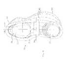
- FIG. 1is a simplified pictorial illustration of footwear constructed and operative in accordance with an embodiment of the present invention
- FIGS. 2 and 3are simplified side-view and rear-view illustrations, respectively, of the footwear of FIG. 1 ;
- FIG. 4is a simplified top-view illustration of the footwear of FIG. 1 , showing further features of other embodiments of the present invention
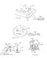
- FIG. 5is a simplified pictorial illustration of a treadmill constructed and operative in accordance with an embodiment of the present invention
- FIG. 6is a simplified pictorial illustration of an exercise surface constructed and operative in accordance with an embodiment of the present invention.
- FIG. 7is a simplified pictorial illustration of an exercise bicycle constructed and operative in accordance with an embodiment of the present invention.
- FIG. 8is a simplified pictorial illustration of an exercise stepper constructed and operative in accordance with an embodiment of the present invention.
- FIG. 9is a simplified pictorial illustration of a ski machine constructed and operative in accordance with an embodiment of the present invention.
- FIG. 10is a simplified pictorial illustration of an elliptic exercise machine constructed and operative in accordance with an embodiment of the present invention.
- FIG. 11is a simplified pictorial illustration of a rowing machine constructed and operative in accordance with an embodiment of the present invention.
- FIGS. 1–4illustrate footwear 10 constructed and operative in accordance with an embodiment of the present invention.
- Footwear 10may be supplied as one or more pairs of shoe-like devices, or alternatively, as just one of the shoe-like devices.
- Footwear 10preferably comprises a support member 12 having a periphery in a shape of a shoe sole with an upper surface 14 .
- the upper surface 14is indented with a peripheral ridge 16 , but it is appreciated that other configurations of upper surface 14 are within the scope of the invention.
- Footwear 10may be attached to a foot of a user (not shown) by means of a boot 18 and/or fasteners 20 , such as but not limited to, VELCRO straps, buckles, shoe laces, and the like.
- Boot 18may be fashioned for attachment to the user's foot with or without fasteners 20 .
- fasteners 20may be used to attach footwear 10 to the user's foot without boot 18 .
- Two bulbous protuberances 22may protrude from a lower surface 24 of support member 12 .
- bulbous protuberances 22may protrude from the upper surface 14 of support member 12 .
- Each protuberance 22may have a curved outer contour 26 .
- the cross-section of the contour 26that is, either the cross-section taken with respect to a longitudinal axis 28 ( FIG. 4 ) of support member 12 (corresponding to the shape seen in FIG. 2 ) or the cross-section taken with respect to a latitudinal axis 30 ( FIG. 4 ) of support member 12 (corresponding to the shape seen in FIG. 3 ), or any other cross-section, may have any curvilinear shape.
- the contours 26may have the shape of a conic section, that is, the shape of a circle, ellipse, parabola or hyperbola.
- the various cross-sections of the contours 26 of protuberance 22may be shaped identically or differently.
- one protuberance 22may be positioned more posteriorly than the other protuberance 22 .
- the protuberancesmay be positioned on a common longitudinal axis of support member 12 , such as the centerline 28 of support member 12 , and on opposite sides of the latitudinal midline 30 .
- the rearward protuberance 22may be positioned generally underneath a calcaneus (heel, ankle) support portion 23 of support member 12
- the forward protuberance 22may be positioned generally underneath a metatarsals support portion 25 and/or phalanges support portion 27 of support member 12 .
- one of the protuberances 22may be aligned on a longitudinal axis 34 offset from centerline 28 , and the rearward protuberance 22 may be positioned offset from axis 34 , such as on the centerline 28 . It is appreciated that the above are just some examples of positioning the protuberances 22 , and many other possibilities exist within the scope of the invention.
- the protuberances 22may be constructed of any suitable material, such as but not limited to, elastomers or metal or a combination of materials, and may have different properties.
- the protuberancesmay have different resilience or hardness, such as having different elasticity properties or Shore hardness.
- the protuberances 22may protrude by different amounts from the lower surface 24 of support member 12 .
- one or more protuberances 22may be slidingly mounted on support member 12 .
- protuberance 22may be mounted on a track 36 ( FIG. 2 ) formed in the lower surface 24 of support member 12 , and may be selectively positioned anywhere along the track and fastened thereto.
- Track 36may extend along a portion of the shoe sole or all along the length of the shoe sole.
- the amount of protrusion of protuberance 22may be adjusted, such as by mounting protuberance 22 with a threaded fastener 38 ( FIG. 3 ) to support member 12 and tightening or releasing threaded fastener 38 .
- Protuberances 39may be formed in the shape of a peg, stud, bolt, pin, dowel and the like, although the invention is not limited to these shapes. Protuberances 39 may be rigid or flexible. As with protuberances 22 , the protuberances 39 may have different resilience or hardness, such as having different elasticity properties or Shore hardness, and they may protrude by different amounts from the lower surface 24 of support member 12 . As above, the amount of protrusion of protuberances 39 may be adjusted. Protuberances 39 may be mounted at any place on the lower surface 24 of support member 12 .
- footwear 10may have a normal outer sole and have a sliding/shifting mechanism for the protuberances 22 inside the sole of footwear 10 .
- the sliding/shifting mechanismmay comprise, without limitation, a mechanism that floats in a viscous matrix (e.g., fluid in a chamber formed in the sole) or that is suspended by inner cables.
- footwear 10may comprise a flange 40 that extends outwards from the periphery of support member 12 .
- flange 40extends sideways outwards from the periphery of support member 12 , but it is appreciated that flange 40 may extend forwards or rearwards or in any other direction as well.
- Flange 40may be provided on one side of footwear 10 , as illustrated, or may be provided on both sides.
- Flange 40may supplement the range of proprioceptive exercises possible with footwear 10 , by providing an additional support surface during tilting and maneuvering with footwear 10 .
- Flange 40may be constructed of any suitable material, such as but not limited to, elastomers or metal or a combination of materials, and may have portions 42 with different properties.
- portions 42may have different resilience or hardness, such as having different elasticity properties or Shore hardness.
- the portions 42 of flange 40may have differently curved contours. Flange 40 may be adjustably attached to support member 12 such that the amount that flange 40 extends from support member 12 is adjustable.
- footwear 10may be used to reestablish neuromuscular control during rehabilitation of joints, to restore the mechanical and functional stability of the neuromuscular system, to improve or rehabilitate anticipatory (feed-forward) and reflexive (feed-back) neuromuscular control mechanism, and to regain and improve balance, postural equilibrium and core stability.
- FIG. 5illustrates a treadmill 50 constructed and operative in accordance with an embodiment of the present invention.
- Treadmill 50may comprise a foot-contact running surface 52 that rotates about a pair of spaced pulleys 54 .
- Running surface 52may comprise one or more protuberances 56 protruding upwards from running surface 52 .
- Protuberances 56may be of different or similar configuration (e.g., height, size, shape and/or slope).
- Protuberances 56may have a fixed size/shape, or alternatively, may have a variable size/shape.
- the variable size/shapemay be achieved by constructing protuberance 56 from an inflatable element, which may be inflated pneumatically with air or hydraulically with a liquid (e.g., water or oil).
- a controller 58may be provided that controls inflation and deflation of protuberances 56 .
- Protuberances 56 and/or running surface 52may have different or similar material properties. For example, they may have different or similar resilience or viscosity (in the inflatable version) and may be made of different or similar materials.
- Protuberances 56may be movable.
- one or more of the protuberances 56may be translatable such as in a track 57 (e.g., forwards, backwards, sideways or diagonally) and/or rotatable about its own or other axis, or a combination of such motions.
- a protective strap(not shown) may be provided to maintain the user in an upright position and help prevent accidental falls.
- Exercise surface 60may comprise one or more protuberances 62 protruding upwards from the upper (foot-contacting) face and/or lower (floor-contacting) face of exercise surface 60 .
- Protuberances 62may be of different or similar configuration (e.g., height, size, shape and/or slope).
- Protuberances 62may have a fixed size/shape, or alternatively, may have a variable size/shape.
- the variable size/shapemay be achieved by constructing protuberance 62 from an inflatable element, which may be inflated pneumatically with air or hydraulically with a liquid (e.g., water or oil).
- a controller 64may be provided that controls inflation and deflation of protuberances 62 .
- Protuberances 62may have different or similar resilience or viscosity (in the inflatable version), and may be made of different or similar materials.
- Protuberances 62may be movable.
- one or more of the protuberances 62may be translatable such as in a track 66 (e.g., forwards, backwards, sideways, radially or diagonally) and/or rotatable about its own or other axis, or a combination of such motions.
- a user of the exercise surface 60may thus move in six degrees of freedom (translating in three mutually orthogonal directions (x, y, z) and rotating about these axes (azimuth, elevation and roll)).
- FIG. 7illustrates a stationary exercise bicycle 70 constructed and operative in accordance with an embodiment of the present invention.
- Exercise bicycle 70may comprise apparatus with its own pedals, wheel and sensors (e.g., speedometer, odometer, etc.) or may comprise an indoor bicycle trainer, wherein a user mounts a bicycle to a stand, which permits pedaling the bicycle while the bicycle remains stationary.
- Exercise bicycle 70may comprise a bumping mechanism 72 connected to a front axle 74 or rear support 75 of bicycle 70 and/or a bumping mechanism 76 connected to a seat 78 of bicycle 70 .
- the bumping mechanismsmay oscillate, rock, bump and otherwise disrupt the balance of the user of the exercise bicycle 70 (as indicated by arrows in FIG. 7 ).
- the bumping mechanismsmay move the rider in six degrees of freedom (translation in three mutually orthogonal directions (x, y, z) and rotation about these axes (azimuth, elevation and roll)).
- the bumping mechanisms in this embodimentmay comprise a plate on which exercise bicycle 70 is mounted, wherein the plate provides the bumping action in six degrees of freedom.
- Exercise bicycle 70may be used to exercise the neuromuscular control in the back, hip, pelvis, ankle, knee and other parts of the body by means of bumps during riding, which may simulate riding on bumpy roads.
- a controller 77may be provided to control operation of bumping mechanism 72 .
- Exercise stepper 80may comprise a controller 82 that varies the resistive force offered by pedals 84 of the stepper 80 . Controller 82 may also vary the angle of the pedals 84 , such as to create eversion and inversion, as indicated by arrows in FIG. 8 . Here too, controller 82 may move the pedals 84 in six degrees of freedom (translation in three mutually orthogonal directions (x, y, z) and rotation about these axes (azimuth, elevation and roll)).
- Ski machine 90may comprise a controller 92 that varies the resistive force offered by ski platforms 94 of the ski 90 . Controller 92 may also vary the angle of ski platforms 94 , such as to create eversion and inversion, as indicated by arrows in FIG. 9 . Controller 92 may move the ski platforms 94 in six degrees of freedom (translation in three mutually orthogonal directions (x, y, z) and rotation about these axes (azimuth, elevation and roll)).
- stationary exercise bicyclesmay utilize only a relatively small number of muscles, throughout a fairly limited range of motion.
- Cross-country skiing devicesmay exercise more muscles than a stationary bicycle, however, the substantially flat shuffling foot motion of the device may limit the range of motion of some of the muscles being exercised.
- Stair climbing devicesmay exercise more muscles than stationary bicycles, however, the limited range of up-and-down motion may not exercise the leg muscles through a large range of motion.
- elliptic exercise machineshave been developed that simulate natural walking and running motions and exercise a large number of muscles through a large range of motion.
- the machinesprovide variable, flexibly coordinated elliptical motion of the leg muscles.
- An example of one of the many elliptic exercise machines in the prior artis described in U.S. Pat. No. 5,848,954.
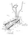
- FIG. 10illustrates an elliptic exercise machine 100 , constructed and operative in accordance with an embodiment of the present invention.
- Elliptic exercise machine 100is shown for convenience with some elements similar to that of U.S. Pat. No. 5,848,954, but it is emphasized that the invention is not limited to this construction. In any case, the proprioceptive features of the invention are not found in U.S. Pat. No. 5,848,954 or any of the prior art.
- Elliptic exercise machine 100may comprise a frame 102 and a linkage assembly 104 movably mounted on frame 102 .
- Linkage assembly 104may generally move relative to frame 102 in a manner that links rotation of a flywheel 106 to generally elliptical motion of a force receiving member or “skate” 108 .
- Frame 102may include a base 110 , a forward stanchion or upright 112 , and a rearward stanchion or upright 114 .
- elliptical motionis intended in a broad sense to describe a closed path of motion having a relatively longer first axis and a relatively shorter second axis (which extends perpendicular to the first axis). It is further noted that in the illustrated embodiment, there is left-right symmetry about a longitudinal axis, and the “right-hand” components are 180° out of phase relative to the “left-hand” components. However, like reference numerals are used to designate both the “right-hand” and “left-hand” parts on elliptic exercise machine 100 , and when reference is made to one or more parts on only one side of the machine, it is to be understood that corresponding part(s) are disposed on the opposite side of the machine.
- the forward stanchion 112may extend perpendicularly upward from base 110 and support a telescoping tube or post 116 .
- a pair of handles 118may be pivotally mounted to post 116 at a pivot 119 .
- Handles 118may have gripping portions 120 .
- a display 122may be disposed on post 116 .
- Skates 108may slide on rails 124 .
- a usermay place his/her foot on a foot-contacting surface 126 of skate 108 .
- elliptic exercise machine 100may comprise one or more bumping mechanisms 130 connected to a front support 132 and/or a rear support 134 of rails 124 .
- the bumping mechanisms 130may oscillate, rock, bump and otherwise disrupt the balance of the user of elliptic exercise machine 100 .
- the bumping mechanisms 130may move the user in six degrees of freedom (translation in three mutually orthogonal directions (x, y, z) and rotation about these axes (azimuth, elevation and roll)).
- a controller 136may be provided to control operation of bumping mechanism 130 .
- Rowing machine 150may comprise a rail 152 on which a seat 154 is slidingly mounted.
- Rail 152may have a rear support 155 .
- Rail 152may extend from a forward-mounted tension drum 156 , which may be mounted on a front support 157 .
- a cord 158may be wound around tension drum 156 .
- Cord 158may be provided with a handle 159 .
- Footrests 160may be mounted on rail 152 .
- a usermay sit on seat 154 , place feet against the footrests 160 , grasp handle 159 and pull cord 158 towards the rear of rowing machine 150 , outwards from tension drum 156 .
- This motionsimulates the action of pulling oars in a rowboat.
- the seat 154may slide back and forth on rail 152 during the rowing motion.
- Tension drum 156resists the pulling action on cord 158 , thereby exercising muscles used in rowing.
- the tension in tension drum 156may be adjusted to suit the desired level of exercise.
- a controller 162may be provided that varies the resistive force offered by tension drum 156 .
- rowing machine 150may comprise one or more bumping mechanisms 164 connected to front support 157 and/or rear support 155 of rail 152 , or to seat 154 .
- the bumping mechanisms 164may oscillate, rock, bump and otherwise disrupt the balance of the user of rowing machine 150 .
- the bumping mechanisms 164may move the user in six degrees of freedom (translation in three mutually orthogonal directions (x, y, z) and rotation about these axes (azimuth, elevation and roll)).
- Controller 162may control operation of bumping mechanisms 164 .
Landscapes
- Health & Medical Sciences (AREA)
- General Health & Medical Sciences (AREA)
- Physical Education & Sports Medicine (AREA)
- Orthopedic Medicine & Surgery (AREA)
- Epidemiology (AREA)
- Public Health (AREA)
- Life Sciences & Earth Sciences (AREA)
- Biophysics (AREA)
- Cardiology (AREA)
- Vascular Medicine (AREA)
- Footwear And Its Accessory, Manufacturing Method And Apparatuses (AREA)
- Rehabilitation Tools (AREA)
Abstract
Description
Claims (3)
Priority Applications (22)
| Application Number | Priority Date | Filing Date | Title |
|---|---|---|---|
| US10/397,419US7101330B2 (en) | 2002-08-19 | 2003-03-27 | Proprioceptive/kinesthetic apparatus and method |
| CNB03819774XACN100467006C (en) | 2002-08-19 | 2003-08-12 | Proprioceptive/kinesthetic device |
| PT80101041TPT1964485E (en) | 2002-08-19 | 2003-08-12 | Proprioceptive/kinesthetic footwear |
| DK08010104.1TDK1964485T3 (en) | 2002-08-19 | 2003-08-12 | Proprioceptive / kinesthetic footwear |
| BRPI0313615-9ABRPI0313615B1 (en) | 2002-08-19 | 2003-08-12 | shoe |
| EP08010104AEP1964485B1 (en) | 2002-08-19 | 2003-08-12 | Proprioceptive/kinesthetic footwear |
| BRPI0313615ABRPI0313615A2 (en) | 2002-08-19 | 2003-08-12 | shoe |
| RU2005106354/12ARU2343946C2 (en) | 2002-08-19 | 2003-08-12 | Proprioceptive/kinesthetic device and method |
| JP2004528791AJP2005536247A (en) | 2002-08-19 | 2003-08-12 | Body position sense / motor sense device and method |
| CA2495723ACA2495723C (en) | 2002-08-19 | 2003-08-12 | Proprioceptive/kinesthetic apparatus and method |
| KR1020057002735AKR101189471B1 (en) | 2002-08-19 | 2003-08-12 | Proprioceptive and kinesthetic footwear |
| PCT/IL2003/000668WO2004016321A2 (en) | 2002-08-19 | 2003-08-12 | Proprioceptive/kinesthetic apparatus and method |
| EP10010992.5AEP2277607A3 (en) | 2002-08-19 | 2003-08-12 | Proprioceptive/kinesthetic apparatus and method |
| EP03787989AEP1530495A2 (en) | 2002-08-19 | 2003-08-12 | Proprioceptive/kinesthetic apparatus and method |
| SI200332229TSI1964485T1 (en) | 2002-08-19 | 2003-08-12 | Proprioceptive/kinesthetic footwear |
| ES08010104TES2397161T3 (en) | 2002-08-19 | 2003-08-12 | Proprioceptive / Kinetic Footwear |
| NZ538361ANZ538361A (en) | 2002-08-19 | 2003-08-12 | Proprioceptive/kinesthetic footwear |
| AU2003250510AAU2003250510B2 (en) | 2002-08-19 | 2003-08-12 | Proprioceptive/kinesthetic apparatus and method |
| UAA200501681AUA87443C2 (en) | 2002-08-19 | 2003-08-12 | Proprioceptive or kinesthetic exercise apparatus |
| MXPA05001955AMXPA05001955A (en) | 2002-08-19 | 2003-08-12 | Proprioceptive/kinesthetic apparatus and method. |
| NO20051396ANO325642B1 (en) | 2002-08-19 | 2005-03-17 | Footwear for increasing proprioceptive and kinesthetic skills. |
| US11/515,383US20080242518A1 (en) | 2002-08-19 | 2006-09-05 | Proprioceptive/kinesthetic apparatus and method |
Applications Claiming Priority (2)
| Application Number | Priority Date | Filing Date | Title |
|---|---|---|---|
| US10/222,992US6979287B2 (en) | 2002-08-19 | 2002-08-19 | Proprioceptive and kinesthetic footwear |
| US10/397,419US7101330B2 (en) | 2002-08-19 | 2003-03-27 | Proprioceptive/kinesthetic apparatus and method |
Related Parent Applications (1)
| Application Number | Title | Priority Date | Filing Date |
|---|---|---|---|
| US10/222,992Continuation-In-PartUS6979287B2 (en) | 2002-08-19 | 2002-08-19 | Proprioceptive and kinesthetic footwear |
Related Child Applications (1)
| Application Number | Title | Priority Date | Filing Date |
|---|---|---|---|
| US11/515,383ContinuationUS20080242518A1 (en) | 2002-08-19 | 2006-09-05 | Proprioceptive/kinesthetic apparatus and method |
Publications (2)
| Publication Number | Publication Date |
|---|---|
| US20040033864A1 US20040033864A1 (en) | 2004-02-19 |
| US7101330B2true US7101330B2 (en) | 2006-09-05 |
Family
ID=31715096
Family Applications (4)
| Application Number | Title | Priority Date | Filing Date |
|---|---|---|---|
| US10/222,992Expired - LifetimeUS6979287B2 (en) | 2002-08-19 | 2002-08-19 | Proprioceptive and kinesthetic footwear |
| US10/397,419Expired - LifetimeUS7101330B2 (en) | 2002-08-19 | 2003-03-27 | Proprioceptive/kinesthetic apparatus and method |
| US11/515,383AbandonedUS20080242518A1 (en) | 2002-08-19 | 2006-09-05 | Proprioceptive/kinesthetic apparatus and method |
| US12/636,800AbandonedUS20100093500A1 (en) | 2002-08-19 | 2009-12-14 | Proprioceptive/kinesthetic apparatus and method |
Family Applications Before (1)
| Application Number | Title | Priority Date | Filing Date |
|---|---|---|---|
| US10/222,992Expired - LifetimeUS6979287B2 (en) | 2002-08-19 | 2002-08-19 | Proprioceptive and kinesthetic footwear |
Family Applications After (2)
| Application Number | Title | Priority Date | Filing Date |
|---|---|---|---|
| US11/515,383AbandonedUS20080242518A1 (en) | 2002-08-19 | 2006-09-05 | Proprioceptive/kinesthetic apparatus and method |
| US12/636,800AbandonedUS20100093500A1 (en) | 2002-08-19 | 2009-12-14 | Proprioceptive/kinesthetic apparatus and method |
Country Status (9)
| Country | Link |
|---|---|
| US (4) | US6979287B2 (en) |
| EP (2) | EP2277607A3 (en) |
| BR (2) | BRPI0313615B1 (en) |
| DK (1) | DK1964485T3 (en) |
| ES (1) | ES2397161T3 (en) |
| PT (1) | PT1964485E (en) |
| SI (1) | SI1964485T1 (en) |
| UA (1) | UA87443C2 (en) |
| ZA (1) | ZA200501726B (en) |
Cited By (51)
| Publication number | Priority date | Publication date | Assignee | Title |
|---|---|---|---|---|
| US20090165333A1 (en)* | 1994-01-26 | 2009-07-02 | Reebok International Ltd. | Support and Cushioning System for an Article of Footwear |
| US20090197744A1 (en)* | 2006-06-26 | 2009-08-06 | Iwao Yamazaki | Exercise machine |
| US20090318274A1 (en)* | 2008-06-18 | 2009-12-24 | Christopher Welsh | Balance trainer |
| US20100093500A1 (en)* | 2002-08-19 | 2010-04-15 | Avi Elbaz | Proprioceptive/kinesthetic apparatus and method |
| US20100145233A1 (en)* | 2007-03-22 | 2010-06-10 | Rehabtek Llc | System and method for training human subjects to improve off-axis neuromuscular control of the lower limbs |
| US20100251565A1 (en)* | 2009-04-01 | 2010-10-07 | Reebok International Ltd. | Training Footwear |
| US20100251567A1 (en)* | 2009-04-01 | 2010-10-07 | Reebok International Ltd. | Training Footwear |
| US20100325919A1 (en)* | 2002-08-19 | 2010-12-30 | Avi Elbaz | Proprioceptive/kinesthetic apparatus and method |
| USD648517S1 (en) | 2008-09-26 | 2011-11-15 | Reebok International Ltd. | Portion of a shoe sole |
| US20120260419A1 (en)* | 2011-04-13 | 2012-10-18 | Matthew James Mangiacopra | Patient transfer apparatus and method |
| USD671304S1 (en) | 2009-09-28 | 2012-11-27 | Reebok International Limited | Shoe sole |
| USD677040S1 (en) | 2010-11-17 | 2013-03-05 | Reebok International Limited | Shoe |
| USD677041S1 (en) | 2010-09-20 | 2013-03-05 | The Rockport Company, Llc | Heel of a shoe sole |
| USD677866S1 (en) | 2010-09-24 | 2013-03-19 | Reebok International Limited | Shoe |
| USD683118S1 (en) | 2011-03-10 | 2013-05-28 | New Balance Athletic Shoe, Inc. | Shoe sole |
| USD719331S1 (en) | 2012-03-23 | 2014-12-16 | Reebok International Limited | Shoe |
| USD722750S1 (en) | 2012-09-07 | 2015-02-24 | Reebok International Limited | Shoe |
| US20150119767A1 (en)* | 2011-12-08 | 2015-04-30 | Apos-Medical And Sports Technologies Ltd. | Device and methods fo treating neurological disorders |
| US9357812B2 (en) | 2002-08-19 | 2016-06-07 | APOS—Medical and Sports Technologies Ltd. | Proprioceptive/kinesthetic apparatus and method |
| US9861509B2 (en) | 2010-06-29 | 2018-01-09 | APOS—Medical and Sports Technologies Ltd. | Device and methods for treating a lower limb joint pathology and lower limb pain |
| US10010743B2 (en) | 2010-07-02 | 2018-07-03 | APOS—Medical and Sports Technology Ltd. | Device and methods for tuning a skeletal muscle |
| US10188890B2 (en) | 2013-12-26 | 2019-01-29 | Icon Health & Fitness, Inc. | Magnetic resistance mechanism in a cable machine |
| US10252109B2 (en) | 2016-05-13 | 2019-04-09 | Icon Health & Fitness, Inc. | Weight platform treadmill |
| US10258828B2 (en) | 2015-01-16 | 2019-04-16 | Icon Health & Fitness, Inc. | Controls for an exercise device |
| US10272317B2 (en) | 2016-03-18 | 2019-04-30 | Icon Health & Fitness, Inc. | Lighted pace feature in a treadmill |
| US10279212B2 (en) | 2013-03-14 | 2019-05-07 | Icon Health & Fitness, Inc. | Strength training apparatus with flywheel and related methods |
| US10293211B2 (en) | 2016-03-18 | 2019-05-21 | Icon Health & Fitness, Inc. | Coordinated weight selection |
| US10343017B2 (en) | 2016-11-01 | 2019-07-09 | Icon Health & Fitness, Inc. | Distance sensor for console positioning |
| US10376736B2 (en) | 2016-10-12 | 2019-08-13 | Icon Health & Fitness, Inc. | Cooling an exercise device during a dive motor runway condition |
| US10426989B2 (en) | 2014-06-09 | 2019-10-01 | Icon Health & Fitness, Inc. | Cable system incorporated into a treadmill |
| US10433612B2 (en) | 2014-03-10 | 2019-10-08 | Icon Health & Fitness, Inc. | Pressure sensor to quantify work |
| US10441844B2 (en) | 2016-07-01 | 2019-10-15 | Icon Health & Fitness, Inc. | Cooling systems and methods for exercise equipment |
| US10471299B2 (en) | 2016-07-01 | 2019-11-12 | Icon Health & Fitness, Inc. | Systems and methods for cooling internal exercise equipment components |
| US10493349B2 (en) | 2016-03-18 | 2019-12-03 | Icon Health & Fitness, Inc. | Display on exercise device |
| US10500473B2 (en) | 2016-10-10 | 2019-12-10 | Icon Health & Fitness, Inc. | Console positioning |
| US10537764B2 (en) | 2015-08-07 | 2020-01-21 | Icon Health & Fitness, Inc. | Emergency stop with magnetic brake for an exercise device |
| US10543395B2 (en) | 2016-12-05 | 2020-01-28 | Icon Health & Fitness, Inc. | Offsetting treadmill deck weight during operation |
| US10561877B2 (en) | 2016-11-01 | 2020-02-18 | Icon Health & Fitness, Inc. | Drop-in pivot configuration for stationary bike |
| US10561894B2 (en) | 2016-03-18 | 2020-02-18 | Icon Health & Fitness, Inc. | Treadmill with removable supports |
| US10625114B2 (en) | 2016-11-01 | 2020-04-21 | Icon Health & Fitness, Inc. | Elliptical and stationary bicycle apparatus including row functionality |
| US10625137B2 (en) | 2016-03-18 | 2020-04-21 | Icon Health & Fitness, Inc. | Coordinated displays in an exercise device |
| US10661114B2 (en) | 2016-11-01 | 2020-05-26 | Icon Health & Fitness, Inc. | Body weight lift mechanism on treadmill |
| US10702736B2 (en) | 2017-01-14 | 2020-07-07 | Icon Health & Fitness, Inc. | Exercise cycle |
| US10729965B2 (en) | 2017-12-22 | 2020-08-04 | Icon Health & Fitness, Inc. | Audible belt guide in a treadmill |
| US10750812B2 (en) | 2015-06-11 | 2020-08-25 | Apos Medical Assets Ltd. | Modular footwear protuberance assembly |
| US10953305B2 (en) | 2015-08-26 | 2021-03-23 | Icon Health & Fitness, Inc. | Strength exercise mechanisms |
| USD963302S1 (en) | 2020-07-20 | 2022-09-13 | Apos Medical Assets Ltd. | Shoe |
| US11451108B2 (en) | 2017-08-16 | 2022-09-20 | Ifit Inc. | Systems and methods for axial impact resistance in electric motors |
| US11896078B2 (en) | 2021-07-29 | 2024-02-13 | Apos Medical Assets Ltd. | Footwear having an outsole for reducing limb or back pain |
| USD1025570S1 (en) | 2020-07-15 | 2024-05-07 | Apos Medical Assets Ltd. | Pair of attachments to shoe soles for the purposes of mapping the shape of a foot for footwear |
| US12133574B2 (en) | 2018-12-13 | 2024-11-05 | Apos Medical Assets Ltd. | Footwear with a movable protuberance and an outsole map for protuberance positioning |
Families Citing this family (34)
| Publication number | Priority date | Publication date | Assignee | Title |
|---|---|---|---|---|
| US7621850B2 (en)* | 2003-02-28 | 2009-11-24 | Nautilus, Inc. | Dual deck exercise device |
| US7553260B2 (en) | 2003-02-28 | 2009-06-30 | Nautilus, Inc. | Exercise device with treadles |
| US7166528B2 (en) | 2003-10-10 | 2007-01-23 | Applied Materials, Inc. | Methods of selective deposition of heavily doped epitaxial SiGe |
| US7462158B2 (en)* | 2004-05-07 | 2008-12-09 | Amit Mor | Bone-growth stimulator |
| US7312128B2 (en)* | 2004-12-01 | 2007-12-25 | Applied Materials, Inc. | Selective epitaxy process with alternating gas supply |
| US20070032359A1 (en)* | 2005-08-02 | 2007-02-08 | Brian Toronto | Proprioception enhancement bands |
| US20070060451A1 (en)* | 2005-09-12 | 2007-03-15 | Scott Lucas | Treadmill with uneven nonuniform surface |
| US20090029831A1 (en) | 2007-03-30 | 2009-01-29 | Nautilus, Inc. | Device and method for limiting travel in an exercise device, and an exercise device including such a limiting device |
| EP2254671A1 (en) | 2008-01-31 | 2010-12-01 | Jeffrey David Stewart | Exercise apparatuses and methods of using the same |
| US7918811B2 (en)* | 2008-08-05 | 2011-04-05 | Adidas International Marketing B.V. | Support device for a joint |
| US8533980B2 (en)* | 2008-08-31 | 2013-09-17 | APOS—Medical and Sports Technologies Ltd. | Map for footwear |
| US20110126422A1 (en)* | 2009-12-02 | 2011-06-02 | Brown Shoe Company, Inc. | Shoe sole with compressible protruding element |
| KR101924349B1 (en)* | 2010-07-21 | 2018-12-03 | 아포스-메디컬 앤드 스포츠 테크놀로지즈 엘티디. | Medical footwear |
| FR2972103A1 (en)* | 2011-03-03 | 2012-09-07 | Thierry Maurice Marie Buand | Device for forming heel that is utilized for sole of sports shoe for balancing purpose in three planes of space, has damping pad located under heel, where pad overcomes imbalances in promontory and provides protection to ankle articulations |
| US10863791B2 (en) | 2011-04-07 | 2020-12-15 | Ovation Medical | Removable leg walker |
| US20150321051A1 (en)* | 2011-10-10 | 2015-11-12 | Jeffrey Olson | Stability Platform |
| US9247784B2 (en) | 2012-06-22 | 2016-02-02 | Jeffrey David Stewart | Wearable exercise apparatuses |
| US9248042B2 (en) | 2012-09-12 | 2016-02-02 | Yessenia Lopez | Dorsal foot splint |
| US9220944B2 (en)* | 2013-02-12 | 2015-12-29 | Balance Designs, Inc. | Apparatus for exercise and balance training |
| WO2014144517A1 (en) | 2013-03-15 | 2014-09-18 | Ovation Medical | Orthopedic walking boot with heel cushion |
| US10449078B2 (en) | 2013-03-15 | 2019-10-22 | Ovation Medical | Modular system for an orthopedic walking boot |
| US10085871B2 (en) | 2013-03-15 | 2018-10-02 | Ovation Systems | Overmolding for an orthopedic walking boot |
| US20150208760A1 (en)* | 2014-01-24 | 2015-07-30 | Tung-Cheng Chen | Sole for rehabilitation footwear |
| US9510965B2 (en) | 2014-07-01 | 2016-12-06 | Ortho Systems | Adjustable walking apparatus |
| CN104146850B (en)* | 2014-07-31 | 2016-05-04 | 上海交通大学 | A kind of rehabilitation air mattrens shoes that imitates walking dynamic mode |
| WO2017069732A1 (en)* | 2015-10-19 | 2017-04-27 | Racestl | Therapy device and method of manufacturing the same |
| US10449403B2 (en) | 2016-03-31 | 2019-10-22 | Accessportamerica, Inc. | Gait pattern training device |
| WO2019058380A1 (en) | 2017-09-24 | 2019-03-28 | Technion Research And Development Foundation Limited | A robotic shoe for diagnosis and rehabilitation of gait anomalies |
| USD846130S1 (en) | 2018-01-31 | 2019-04-16 | Ortho Systems | Knee brace |
| WO2020086792A1 (en)* | 2018-10-25 | 2020-04-30 | University Of Florida Research Foundation, Incorporated | Gait modification apparatuses, systems and methods |
| EP4093231A4 (en)* | 2020-01-23 | 2024-01-31 | APOS Medical Assets Ltd. | Footwear with protuberances and construction thereof |
| US12005306B2 (en)* | 2021-06-28 | 2024-06-11 | Brendan Hogan | Swing trainer balance block apparatus |
| CN113491619B (en)* | 2021-07-14 | 2023-06-02 | 嘉应学院 | A multifunctional aerobics body training teaching device |
| CN113519964B (en)* | 2021-07-20 | 2022-10-11 | 中国人民解放军陆军军医大学第二附属医院 | Tumble early warning system based on neural network signals |
Citations (1)
| Publication number | Priority date | Publication date | Assignee | Title |
|---|---|---|---|---|
| US20020026730A1 (en)* | 1997-01-22 | 2002-03-07 | Whatley Ian H. | Exercise sole |
Family Cites Families (63)
| Publication number | Priority date | Publication date | Assignee | Title |
|---|---|---|---|---|
| US1021142A (en)* | 1911-04-25 | 1912-03-26 | Malcolm W Freeman | Pneumatic walking attachment. |
| US1529421A (en)* | 1923-06-19 | 1925-03-10 | Eugenie M Dowdell | Amusement device |
| US1736576A (en)* | 1928-12-13 | 1929-11-19 | George W Cable | Elastic shoe sole |
| US2303744A (en)* | 1941-09-11 | 1942-12-01 | Jacobs Maurice | Footgear |
| FR1128009A (en) | 1955-06-17 | 1957-01-02 | Improved sole and footwear or the like provided therewith | |
| DE1907894U (en)* | 1964-07-13 | 1965-01-07 | Wolfgang Jatho | EXERCISE DEVICE FOR ANKLE AND LOWER LEG MUSCLE ACTIVATION. |
| US3402485A (en)* | 1966-05-13 | 1968-09-24 | United Shoe Machinery Corp | Animal track footwear soles |
| IL31581A0 (en) | 1968-02-23 | 1969-04-30 | Hoffmann La Roche | Silyl ethers of steroids and process for their preparation |
| US3859736A (en)* | 1970-04-20 | 1975-01-14 | Nasa | Kinesthetic control simulator |
| US3782011A (en)* | 1972-10-05 | 1974-01-01 | R Fisher | Safety sole for sport shoe |
| US3940128A (en)* | 1975-01-06 | 1976-02-24 | Vitamaster Industries, Inc. | Exercising apparatus |
| US3916538A (en)* | 1975-02-20 | 1975-11-04 | Herbert S Loseff | Walking heel |
| JPS5421142Y2 (en)* | 1976-04-14 | 1979-07-27 | ||
| USRE31173E (en)* | 1976-09-30 | 1983-03-15 | Sporting shoe | |
| US4030213A (en)* | 1976-09-30 | 1977-06-21 | Daswick Alexander C | Sporting shoe |
| US4241523A (en)* | 1978-09-25 | 1980-12-30 | Daswick Alexander C | Shoe sole structure |
| US4348821A (en)* | 1980-06-02 | 1982-09-14 | Daswick Alexander C | Shoe sole structure |
| US4653748A (en)* | 1982-09-30 | 1987-03-31 | Seel Jerry E | Biomechanical ankle platform |
| US4629181A (en)* | 1983-07-21 | 1986-12-16 | Krive Irwin M | Multi-directional movement leg exerciser |
| US4586706A (en)* | 1985-03-13 | 1986-05-06 | Wen-Kuei Lee | Two-stage exercise bike |
| US4660826A (en)* | 1985-09-16 | 1987-04-28 | Lee Wen Kuei | Folding exercise bike |
| NL8502659A (en)* | 1985-09-30 | 1987-04-16 | Matheus Hubertus Gerardus Kier | Spring shoe sole component - comprises non-metallic distorting elastic body e.g. strapped to shoe |
| US4739986A (en)* | 1987-06-05 | 1988-04-26 | Kucharik Edward J | Foot, ankle and lower leg exerciser |
| US4821432A (en)* | 1988-03-25 | 1989-04-18 | Reiber M Andrew | Walking adapter for postsurgical shoes |
| DE68905707T2 (en)* | 1988-08-10 | 1993-08-19 | Tokyo Sintered Metals Corp | BIKE-LIKE TRAINING DEVICE. |
| US5203321A (en)* | 1990-12-11 | 1993-04-20 | Sutter Corporation | Passive anatomic ankle-foot exerciser |
| US5337494A (en)* | 1993-04-28 | 1994-08-16 | Ricker Thomas H | Shoe with retractable cleats |
| JP2824500B2 (en)* | 1994-02-17 | 1998-11-11 | 株式会社アシックス | Hardboard of spike shoes for athletics |
| US5603334A (en)* | 1994-07-25 | 1997-02-18 | Sharp; Gregory M. | Apparatus for measuring and developing proprioceptive ability |
| US5518476A (en)* | 1994-08-22 | 1996-05-21 | Mcleon; Max O. | Triplane foot and biplane ankle exercise apparatus |
| US5897464A (en)* | 1994-08-22 | 1999-04-27 | Mcleod; Max O. | Method and apparatus for ankle exercise |
| US5685807A (en)* | 1995-10-31 | 1997-11-11 | Tong; Kui Kwong | Bouncing boot |
| US5549527A (en)* | 1995-11-08 | 1996-08-27 | Yu; Hui-Nan | Stationary bike |
| US5682690A (en)* | 1996-07-02 | 1997-11-04 | Chang; Shyh-Chye | Footwear with adjustable massage units |
| JP3170638B2 (en)* | 1996-08-08 | 2001-05-28 | 谷 白糸 | Virtual reality experience device |
| JP2917128B2 (en)* | 1996-08-08 | 1999-07-12 | 谷 白糸 | Walking experience device |
| US5915820A (en)* | 1996-08-20 | 1999-06-29 | Adidas A G | Shoe having an internal chassis |
| US5643145A (en)* | 1996-09-18 | 1997-07-01 | Lo; Chung-Yen | Exercise bike |
| AU5506698A (en)* | 1996-12-23 | 1998-07-17 | Svante Berggren | Device for a shoe |
| DE29701013U1 (en)* | 1997-01-22 | 1997-03-20 | Brenner, Raimund, 47119 Duisburg | Side tip shoe with a trained side tip sole for the treatment and avoidance of varicose veins by palpable activation of the leg muscles, for people in sedentary and / or standing work |
| US6063046A (en)* | 1997-04-11 | 2000-05-16 | Allum; John H. | Method and apparatus for the diagnosis and rehabilitation of balance disorders |
| US5848954A (en) | 1997-04-15 | 1998-12-15 | Stearns; Kenneth W. | Exercise methods and apparatus |
| USD448920S1 (en)* | 1998-08-06 | 2001-10-09 | Reebok International Ltd. | Portion of a shoe sole |
| US6126577A (en)* | 1998-09-04 | 2000-10-03 | Chang; Jeffery | Exercise stationary bicycle |
| US6019712A (en)* | 1998-12-30 | 2000-02-01 | Duncan; James Eugene | Dynamic variable resistance balance board |
| US6283897B1 (en) | 1999-04-23 | 2001-09-04 | Blair R. Patton | Ankle and hip strengthening apparatus |
| US6315786B1 (en)* | 1999-07-20 | 2001-11-13 | Partnership Of Arthur H. Smuckler, James Grimes, Niko Efstathiou And Charles A. Sarris | Device for treating heel pain |
| US6176817B1 (en)* | 1999-08-24 | 2001-01-23 | Anthony B. Carey | Exercise and therapy device and method of making same |
| US6311416B1 (en)* | 1999-11-26 | 2001-11-06 | Shimi-Shoe Walking Technologies Ltd. | Therapeutic shoe |
| US6551225B1 (en)* | 2000-01-24 | 2003-04-22 | Ron Richard Romero | Flexible hemispherical exercise |
| US6277057B1 (en)* | 2000-02-28 | 2001-08-21 | Craig Hayden | Ankle rehabilitation device |
| DE10017542A1 (en) | 2000-04-08 | 2001-10-11 | Bosch Gmbh Robert | Device for position and / or speed detection of a rotating part |
| US6811523B1 (en)* | 2000-06-26 | 2004-11-02 | Kirk Timmer | Lower extremity rehabilitation and exercise device |
| WO2002037995A1 (en) | 2000-11-09 | 2002-05-16 | Charles Ogilvie Wood | A shock absorbing device for a shoe |
| US6511404B2 (en)* | 2001-04-04 | 2003-01-28 | Hsueh-Ho Tu | Exercise machine capable of training and soothing muscles |
| US6652432B2 (en)* | 2001-08-15 | 2003-11-25 | Robert S. Smith | Balance therapy platform |
| US6692419B2 (en)* | 2002-01-24 | 2004-02-17 | Ping Chen | Exerciser |
| US20030148865A1 (en)* | 2002-02-07 | 2003-08-07 | Handshoe Ron P. | Apparatus and method for muscle strengthening and rehabilitation |
| EP1494762B1 (en)* | 2002-04-17 | 2012-09-26 | Perry Dynamics, Inc. | Proprioception machine |
| US6979287B2 (en)* | 2002-08-19 | 2005-12-27 | Avi Elbaz | Proprioceptive and kinesthetic footwear |
| US20040053751A1 (en)* | 2002-09-16 | 2004-03-18 | Pizolato Jesse Albert | Bicycle trainer allowing laterial rocking motion |
| US6793609B1 (en)* | 2003-03-04 | 2004-09-21 | Jeeng-Neng Fan | Stationary exercise cycle |
| US7081070B1 (en)* | 2004-06-30 | 2006-07-25 | Kenneth R. Washington | Articulating exercise bicycle platform |
- 2002
- 2002-08-19USUS10/222,992patent/US6979287B2/ennot_activeExpired - Lifetime
- 2003
- 2003-03-27USUS10/397,419patent/US7101330B2/ennot_activeExpired - Lifetime
- 2003-08-12EPEP10010992.5Apatent/EP2277607A3/ennot_activeWithdrawn
- 2003-08-12UAUAA200501681Apatent/UA87443C2/enunknown
- 2003-08-12DKDK08010104.1Tpatent/DK1964485T3/enactive
- 2003-08-12SISI200332229Tpatent/SI1964485T1/enunknown
- 2003-08-12PTPT80101041Tpatent/PT1964485E/enunknown
- 2003-08-12BRBRPI0313615-9Apatent/BRPI0313615B1/enunknown
- 2003-08-12ESES08010104Tpatent/ES2397161T3/ennot_activeExpired - Lifetime
- 2003-08-12BRBRPI0313615Apatent/BRPI0313615A2/enactiveIP Right Grant
- 2003-08-12EPEP08010104Apatent/EP1964485B1/ennot_activeExpired - Lifetime
- 2005
- 2005-02-28ZAZA200501726Apatent/ZA200501726B/enunknown
- 2006
- 2006-09-05USUS11/515,383patent/US20080242518A1/ennot_activeAbandoned
- 2009
- 2009-12-14USUS12/636,800patent/US20100093500A1/ennot_activeAbandoned
Patent Citations (1)
| Publication number | Priority date | Publication date | Assignee | Title |
|---|---|---|---|---|
| US20020026730A1 (en)* | 1997-01-22 | 2002-03-07 | Whatley Ian H. | Exercise sole |
Cited By (77)
| Publication number | Priority date | Publication date | Assignee | Title |
|---|---|---|---|---|
| US8434244B2 (en) | 1994-01-26 | 2013-05-07 | Reebok International Limited | Support and cushioning system for an article of footwear |
| US20090165333A1 (en)* | 1994-01-26 | 2009-07-02 | Reebok International Ltd. | Support and Cushioning System for an Article of Footwear |
| US20100093500A1 (en)* | 2002-08-19 | 2010-04-15 | Avi Elbaz | Proprioceptive/kinesthetic apparatus and method |
| US9357812B2 (en) | 2002-08-19 | 2016-06-07 | APOS—Medical and Sports Technologies Ltd. | Proprioceptive/kinesthetic apparatus and method |
| US9055788B2 (en) | 2002-08-19 | 2015-06-16 | APOS—Medical and Sports Technologies Ltd. | Proprioceptive/kinesthetic apparatus and method |
| US20100325919A1 (en)* | 2002-08-19 | 2010-12-30 | Avi Elbaz | Proprioceptive/kinesthetic apparatus and method |
| US9788597B2 (en) | 2002-08-19 | 2017-10-17 | APOS—Medical and Sports Technologies Ltd. | Proprioceptive/kinesthetic apparatus and method |
| US8758207B2 (en) | 2002-08-19 | 2014-06-24 | APOS—Medical and Sports Technologies Ltd. | Proprioceptive/kinesthetic apparatus and method |
| US20090197744A1 (en)* | 2006-06-26 | 2009-08-06 | Iwao Yamazaki | Exercise machine |
| US20100145233A1 (en)* | 2007-03-22 | 2010-06-10 | Rehabtek Llc | System and method for training human subjects to improve off-axis neuromuscular control of the lower limbs |
| US8636627B2 (en) | 2007-03-22 | 2014-01-28 | Rehabtek Llc | System and method for training human subjects to improve off-axis neuromuscular control of the lower limbs |
| US20090318274A1 (en)* | 2008-06-18 | 2009-12-24 | Christopher Welsh | Balance trainer |
| USD648517S1 (en) | 2008-09-26 | 2011-11-15 | Reebok International Ltd. | Portion of a shoe sole |
| USD807623S1 (en) | 2008-09-26 | 2018-01-16 | Reebok International Limited | Shoe sole |
| USD682518S1 (en) | 2008-09-26 | 2013-05-21 | Reebok International Limited | Shoe sole |
| USD747596S1 (en) | 2008-09-26 | 2016-01-19 | Reebok International Limited | Shoe sole |
| USD697704S1 (en)* | 2008-09-26 | 2014-01-21 | Reebok International Limited | Shoe sole |
| US9462846B2 (en) | 2009-04-01 | 2016-10-11 | Reebok International Limited | Training footwear |
| US8424221B2 (en) | 2009-04-01 | 2013-04-23 | Reebok International Limited | Training footwear |
| US20100251565A1 (en)* | 2009-04-01 | 2010-10-07 | Reebok International Ltd. | Training Footwear |
| US20100251567A1 (en)* | 2009-04-01 | 2010-10-07 | Reebok International Ltd. | Training Footwear |
| US8307569B2 (en) | 2009-04-01 | 2012-11-13 | Reebok International Limited | Training footwear |
| US8713817B2 (en) | 2009-04-01 | 2014-05-06 | Reebok International Limited | Training Footwear |
| USD671304S1 (en) | 2009-09-28 | 2012-11-27 | Reebok International Limited | Shoe sole |
| US10632006B2 (en) | 2010-06-29 | 2020-04-28 | Apos Medical Assets Ltd. | Device and methods for treating a lower limb joint pathology and lower limb pain |
| US9861509B2 (en) | 2010-06-29 | 2018-01-09 | APOS—Medical and Sports Technologies Ltd. | Device and methods for treating a lower limb joint pathology and lower limb pain |
| US11504571B2 (en) | 2010-07-02 | 2022-11-22 | Apos Medical Assets Ltd. | Device and methods for tuning a skeletal muscle |
| US10744368B2 (en) | 2010-07-02 | 2020-08-18 | Apos Medical And Sports Technologies Ltd. | Device and methods for tuning a skeletal muscle |
| US10010743B2 (en) | 2010-07-02 | 2018-07-03 | APOS—Medical and Sports Technology Ltd. | Device and methods for tuning a skeletal muscle |
| USD677041S1 (en) | 2010-09-20 | 2013-03-05 | The Rockport Company, Llc | Heel of a shoe sole |
| USD697293S1 (en)* | 2010-09-24 | 2014-01-14 | Reebok International Limited | Shoe |
| USD762365S1 (en) | 2010-09-24 | 2016-08-02 | Reebok International Limited | Shoe |
| USD677866S1 (en) | 2010-09-24 | 2013-03-19 | Reebok International Limited | Shoe |
| USD677040S1 (en) | 2010-11-17 | 2013-03-05 | Reebok International Limited | Shoe |
| USD683118S1 (en) | 2011-03-10 | 2013-05-28 | New Balance Athletic Shoe, Inc. | Shoe sole |
| US20120260419A1 (en)* | 2011-04-13 | 2012-10-18 | Matthew James Mangiacopra | Patient transfer apparatus and method |
| US9693927B2 (en)* | 2011-12-08 | 2017-07-04 | APOS—Medical and Sports Technologies Ltd. | Device and methods of treating neurological disorders |
| US20150119767A1 (en)* | 2011-12-08 | 2015-04-30 | Apos-Medical And Sports Technologies Ltd. | Device and methods fo treating neurological disorders |
| USD838452S1 (en) | 2012-03-23 | 2019-01-22 | Reebok International Limited | Shoe |
| USD719331S1 (en) | 2012-03-23 | 2014-12-16 | Reebok International Limited | Shoe |
| USD906655S1 (en) | 2012-03-23 | 2021-01-05 | Reebok International Limited | Shoe |
| USD779179S1 (en) | 2012-03-23 | 2017-02-21 | Reebok International Limited | Shoe |
| USD1036836S1 (en) | 2012-03-23 | 2024-07-30 | Reebok International Limited | Shoe |
| USD722750S1 (en) | 2012-09-07 | 2015-02-24 | Reebok International Limited | Shoe |
| US10279212B2 (en) | 2013-03-14 | 2019-05-07 | Icon Health & Fitness, Inc. | Strength training apparatus with flywheel and related methods |
| US10188890B2 (en) | 2013-12-26 | 2019-01-29 | Icon Health & Fitness, Inc. | Magnetic resistance mechanism in a cable machine |
| US10433612B2 (en) | 2014-03-10 | 2019-10-08 | Icon Health & Fitness, Inc. | Pressure sensor to quantify work |
| US10426989B2 (en) | 2014-06-09 | 2019-10-01 | Icon Health & Fitness, Inc. | Cable system incorporated into a treadmill |
| US10258828B2 (en) | 2015-01-16 | 2019-04-16 | Icon Health & Fitness, Inc. | Controls for an exercise device |
| US12029278B2 (en) | 2015-06-11 | 2024-07-09 | Apos Medical Assets Ltd. | Modular footwear protuberance assembly |
| US11363852B2 (en) | 2015-06-11 | 2022-06-21 | Apos Medical Assets Ltd. | Modular footwear protuberance assembly |
| US12290145B2 (en) | 2015-06-11 | 2025-05-06 | Apos Medical Assets Ltd. | Modular footwear protuberance assembly |
| US10750812B2 (en) | 2015-06-11 | 2020-08-25 | Apos Medical Assets Ltd. | Modular footwear protuberance assembly |
| US10537764B2 (en) | 2015-08-07 | 2020-01-21 | Icon Health & Fitness, Inc. | Emergency stop with magnetic brake for an exercise device |
| US10953305B2 (en) | 2015-08-26 | 2021-03-23 | Icon Health & Fitness, Inc. | Strength exercise mechanisms |
| US10561894B2 (en) | 2016-03-18 | 2020-02-18 | Icon Health & Fitness, Inc. | Treadmill with removable supports |
| US10625137B2 (en) | 2016-03-18 | 2020-04-21 | Icon Health & Fitness, Inc. | Coordinated displays in an exercise device |
| US10272317B2 (en) | 2016-03-18 | 2019-04-30 | Icon Health & Fitness, Inc. | Lighted pace feature in a treadmill |
| US10293211B2 (en) | 2016-03-18 | 2019-05-21 | Icon Health & Fitness, Inc. | Coordinated weight selection |
| US10493349B2 (en) | 2016-03-18 | 2019-12-03 | Icon Health & Fitness, Inc. | Display on exercise device |
| US10252109B2 (en) | 2016-05-13 | 2019-04-09 | Icon Health & Fitness, Inc. | Weight platform treadmill |
| US10471299B2 (en) | 2016-07-01 | 2019-11-12 | Icon Health & Fitness, Inc. | Systems and methods for cooling internal exercise equipment components |
| US10441844B2 (en) | 2016-07-01 | 2019-10-15 | Icon Health & Fitness, Inc. | Cooling systems and methods for exercise equipment |
| US10500473B2 (en) | 2016-10-10 | 2019-12-10 | Icon Health & Fitness, Inc. | Console positioning |
| US10376736B2 (en) | 2016-10-12 | 2019-08-13 | Icon Health & Fitness, Inc. | Cooling an exercise device during a dive motor runway condition |
| US10661114B2 (en) | 2016-11-01 | 2020-05-26 | Icon Health & Fitness, Inc. | Body weight lift mechanism on treadmill |
| US10343017B2 (en) | 2016-11-01 | 2019-07-09 | Icon Health & Fitness, Inc. | Distance sensor for console positioning |
| US10561877B2 (en) | 2016-11-01 | 2020-02-18 | Icon Health & Fitness, Inc. | Drop-in pivot configuration for stationary bike |
| US10625114B2 (en) | 2016-11-01 | 2020-04-21 | Icon Health & Fitness, Inc. | Elliptical and stationary bicycle apparatus including row functionality |
| US10543395B2 (en) | 2016-12-05 | 2020-01-28 | Icon Health & Fitness, Inc. | Offsetting treadmill deck weight during operation |
| US10702736B2 (en) | 2017-01-14 | 2020-07-07 | Icon Health & Fitness, Inc. | Exercise cycle |
| US11451108B2 (en) | 2017-08-16 | 2022-09-20 | Ifit Inc. | Systems and methods for axial impact resistance in electric motors |
| US10729965B2 (en) | 2017-12-22 | 2020-08-04 | Icon Health & Fitness, Inc. | Audible belt guide in a treadmill |
| US12133574B2 (en) | 2018-12-13 | 2024-11-05 | Apos Medical Assets Ltd. | Footwear with a movable protuberance and an outsole map for protuberance positioning |
| USD1025570S1 (en) | 2020-07-15 | 2024-05-07 | Apos Medical Assets Ltd. | Pair of attachments to shoe soles for the purposes of mapping the shape of a foot for footwear |
| USD963302S1 (en) | 2020-07-20 | 2022-09-13 | Apos Medical Assets Ltd. | Shoe |
| US11896078B2 (en) | 2021-07-29 | 2024-02-13 | Apos Medical Assets Ltd. | Footwear having an outsole for reducing limb or back pain |
Also Published As
| Publication number | Publication date |
|---|---|
| US20100093500A1 (en) | 2010-04-15 |
| EP2277607A3 (en) | 2014-10-15 |
| BRPI0313615A2 (en) | 2016-06-28 |
| US20080242518A1 (en) | 2008-10-02 |
| EP1964485B1 (en) | 2012-10-10 |
| US20040033874A1 (en) | 2004-02-19 |
| SI1964485T1 (en) | 2013-02-28 |
| BRPI0313615B1 (en) | 2020-11-10 |
| US20040033864A1 (en) | 2004-02-19 |
| ZA200501726B (en) | 2006-05-31 |
| US6979287B2 (en) | 2005-12-27 |
| DK1964485T3 (en) | 2013-01-28 |
| EP1964485A1 (en) | 2008-09-03 |
| UA87443C2 (en) | 2009-07-27 |
| PT1964485E (en) | 2013-01-23 |
| ES2397161T3 (en) | 2013-03-05 |
| EP2277607A2 (en) | 2011-01-26 |
Similar Documents
| Publication | Publication Date | Title |
|---|---|---|
| US7101330B2 (en) | Proprioceptive/kinesthetic apparatus and method | |
| CA2495723C (en) | Proprioceptive/kinesthetic apparatus and method | |
| US9055788B2 (en) | Proprioceptive/kinesthetic apparatus and method | |
| EP1938869B1 (en) | Supplemental resistance assembly for resisting motion of an exercise device | |
| US6283897B1 (en) | Ankle and hip strengthening apparatus | |
| US5879275A (en) | Leg exerciser and method | |
| US4867443A (en) | Cross-country skiing simulator | |
| US7780577B2 (en) | Pendulous exercise device | |
| US9788597B2 (en) | Proprioceptive/kinesthetic apparatus and method | |
| US6063013A (en) | Resistive ankle exercise device | |
| US5490823A (en) | Water therapy and fitness device | |
| IL166971A (en) | Proprioceptive/kinesthetic apparatus and method | |
| JP2004181195A (en) | Sporting apparatus for indoor training such as running/walking | |
| RU2841558C1 (en) | Walking and running exerciser | |
| WO2025181640A1 (en) | Dual sensory balance board and methods of use thereof | |
| WO2025186596A1 (en) | Integrated suspension training equipment | |
| EA008717B1 (en) | Sports trainer for athletes | |
| JP2005169039A (en) | Toe/heel pedal trainer |
Legal Events
| Date | Code | Title | Description |
|---|---|---|---|
| STCF | Information on status: patent grant | Free format text:PATENTED CASE | |
| AS | Assignment | Owner name:APOS - MEDICAL AND SPORTS TECHNOLOGIES LTD., ISRAE Free format text:ASSIGNMENT OF ASSIGNORS INTEREST;ASSIGNORS:ELBAZ, AVI;MOR, AMIT;REEL/FRAME:020431/0937 Effective date:20080124 | |
| FPAY | Fee payment | Year of fee payment:4 | |
| SULP | Surcharge for late payment | ||
| AS | Assignment | Owner name:PLENUS III (D.C.M), LIMITED PARTNERSHIP, ISRAEL Free format text:SECURITY AGREEMENT;ASSIGNOR:APOS - MEDICAL AND SPORTS TECHNOLOGIES LTD.;REEL/FRAME:031106/0085 Effective date:20130828 Owner name:PLENUS III, LIMITED PARTNERSHIP, ISRAEL Free format text:SECURITY AGREEMENT;ASSIGNOR:APOS - MEDICAL AND SPORTS TECHNOLOGIES LTD.;REEL/FRAME:031106/0085 Effective date:20130828 Owner name:PLENUS III (C.I), L.P, ISRAEL Free format text:SECURITY AGREEMENT;ASSIGNOR:APOS - MEDICAL AND SPORTS TECHNOLOGIES LTD.;REEL/FRAME:031106/0085 Effective date:20130828 Owner name:PLENUS MANAGEMENT III 2007 LTD., ISRAEL Free format text:SECURITY AGREEMENT;ASSIGNOR:APOS - MEDICAL AND SPORTS TECHNOLOGIES LTD.;REEL/FRAME:031106/0085 Effective date:20130828 Owner name:PLENUS III (2), LIMITED PARTNERSHIP, ISRAEL Free format text:SECURITY AGREEMENT;ASSIGNOR:APOS - MEDICAL AND SPORTS TECHNOLOGIES LTD.;REEL/FRAME:031106/0085 Effective date:20130828 | |
| FEPP | Fee payment procedure | Free format text:PAYOR NUMBER ASSIGNED (ORIGINAL EVENT CODE: ASPN); ENTITY STATUS OF PATENT OWNER: SMALL ENTITY | |
| FPAY | Fee payment | Year of fee payment:8 | |
| AS | Assignment | Owner name:APOS - MEDICAL AND SPORTS TECHNOLOGIES LTD., ISRAE Free format text:RELEASE BY SECURED PARTY;ASSIGNORS:PLENUS MANAGEMENT III 2007 LTD.;PLENUS III, LIMITED PARTNERSHIP;PLENUS III (D.C.M), LIMITED PARTNERSHIP;AND OTHERS;REEL/FRAME:042701/0969 Effective date:20170606 | |
| MAFP | Maintenance fee payment | Free format text:PAYMENT OF MAINTENANCE FEE, 12TH YR, SMALL ENTITY (ORIGINAL EVENT CODE: M2553) Year of fee payment:12 | |
| AS | Assignment | Owner name:APOS MEDICAL ASSETS LTD., ISRAEL Free format text:ASSIGNMENT OF ASSIGNORS INTEREST;ASSIGNOR:APOS - MEDICAL AND SPORTS TECHNOLOGIES LTD.;REEL/FRAME:046359/0062 Effective date:20180625 |