US7100483B2 - Firing subsystem for use in a fast-acting safety system - Google Patents
Firing subsystem for use in a fast-acting safety systemDownload PDFInfo
- Publication number
- US7100483B2 US7100483B2US09/929,240US92924001AUS7100483B2US 7100483 B2US7100483 B2US 7100483B2US 92924001 AUS92924001 AUS 92924001AUS 7100483 B2US7100483 B2US 7100483B2
- Authority
- US
- United States
- Prior art keywords
- machine
- fusible member
- detection
- brake
- blade
- Prior art date
- Legal status (The legal status is an assumption and is not a legal conclusion. Google has not performed a legal analysis and makes no representation as to the accuracy of the status listed.)
- Expired - Lifetime, expires
Links
Images


Classifications
- F—MECHANICAL ENGINEERING; LIGHTING; HEATING; WEAPONS; BLASTING
- F16—ENGINEERING ELEMENTS AND UNITS; GENERAL MEASURES FOR PRODUCING AND MAINTAINING EFFECTIVE FUNCTIONING OF MACHINES OR INSTALLATIONS; THERMAL INSULATION IN GENERAL
- F16P—SAFETY DEVICES IN GENERAL; SAFETY DEVICES FOR PRESSES
- F16P3/00—Safety devices acting in conjunction with the control or operation of a machine; Control arrangements requiring the simultaneous use of two or more parts of the body
- F16P3/12—Safety devices acting in conjunction with the control or operation of a machine; Control arrangements requiring the simultaneous use of two or more parts of the body with means, e.g. feelers, which in case of the presence of a body part of a person in or near the danger zone influence the control or operation of the machine
- B—PERFORMING OPERATIONS; TRANSPORTING
- B23—MACHINE TOOLS; METAL-WORKING NOT OTHERWISE PROVIDED FOR
- B23D—PLANING; SLOTTING; SHEARING; BROACHING; SAWING; FILING; SCRAPING; LIKE OPERATIONS FOR WORKING METAL BY REMOVING MATERIAL, NOT OTHERWISE PROVIDED FOR
- B23D59/00—Accessories specially designed for sawing machines or sawing devices
- B23D59/001—Measuring or control devices, e.g. for automatic control of work feed pressure on band saw blade
- B—PERFORMING OPERATIONS; TRANSPORTING
- B27—WORKING OR PRESERVING WOOD OR SIMILAR MATERIAL; NAILING OR STAPLING MACHINES IN GENERAL
- B27B—SAWS FOR WOOD OR SIMILAR MATERIAL; COMPONENTS OR ACCESSORIES THEREFOR
- B27B13/00—Band or strap sawing machines; Components or equipment therefor
- B27B13/14—Braking devices specially designed for band sawing machines, e.g. acting after damage of the band saw blade
- B—PERFORMING OPERATIONS; TRANSPORTING
- B27—WORKING OR PRESERVING WOOD OR SIMILAR MATERIAL; NAILING OR STAPLING MACHINES IN GENERAL
- B27B—SAWS FOR WOOD OR SIMILAR MATERIAL; COMPONENTS OR ACCESSORIES THEREFOR
- B27B5/00—Sawing machines working with circular or cylindrical saw blades; Components or equipment therefor
- B27B5/29—Details; Component parts; Accessories
- B27B5/38—Devices for braking the circular saw blade or the saw spindle; Devices for damping vibrations of the circular saw blade, e.g. silencing
- B—PERFORMING OPERATIONS; TRANSPORTING
- B27—WORKING OR PRESERVING WOOD OR SIMILAR MATERIAL; NAILING OR STAPLING MACHINES IN GENERAL
- B27G—ACCESSORY MACHINES OR APPARATUS FOR WORKING WOOD OR SIMILAR MATERIALS; TOOLS FOR WORKING WOOD OR SIMILAR MATERIALS; SAFETY DEVICES FOR WOOD WORKING MACHINES OR TOOLS
- B27G19/00—Safety guards or devices specially adapted for wood saws; Auxiliary devices facilitating proper operation of wood saws
- B27G19/02—Safety guards or devices specially adapted for wood saws; Auxiliary devices facilitating proper operation of wood saws for circular saws
- F—MECHANICAL ENGINEERING; LIGHTING; HEATING; WEAPONS; BLASTING
- F16—ENGINEERING ELEMENTS AND UNITS; GENERAL MEASURES FOR PRODUCING AND MAINTAINING EFFECTIVE FUNCTIONING OF MACHINES OR INSTALLATIONS; THERMAL INSULATION IN GENERAL
- F16P—SAFETY DEVICES IN GENERAL; SAFETY DEVICES FOR PRESSES
- F16P3/00—Safety devices acting in conjunction with the control or operation of a machine; Control arrangements requiring the simultaneous use of two or more parts of the body
- F16P3/12—Safety devices acting in conjunction with the control or operation of a machine; Control arrangements requiring the simultaneous use of two or more parts of the body with means, e.g. feelers, which in case of the presence of a body part of a person in or near the danger zone influence the control or operation of the machine
- F16P3/14—Safety devices acting in conjunction with the control or operation of a machine; Control arrangements requiring the simultaneous use of two or more parts of the body with means, e.g. feelers, which in case of the presence of a body part of a person in or near the danger zone influence the control or operation of the machine the means being photocells or other devices sensitive without mechanical contact
- F16P3/148—Safety devices acting in conjunction with the control or operation of a machine; Control arrangements requiring the simultaneous use of two or more parts of the body with means, e.g. feelers, which in case of the presence of a body part of a person in or near the danger zone influence the control or operation of the machine the means being photocells or other devices sensitive without mechanical contact using capacitive technology
- Y—GENERAL TAGGING OF NEW TECHNOLOGICAL DEVELOPMENTS; GENERAL TAGGING OF CROSS-SECTIONAL TECHNOLOGIES SPANNING OVER SEVERAL SECTIONS OF THE IPC; TECHNICAL SUBJECTS COVERED BY FORMER USPC CROSS-REFERENCE ART COLLECTIONS [XRACs] AND DIGESTS
- Y10—TECHNICAL SUBJECTS COVERED BY FORMER USPC
- Y10S—TECHNICAL SUBJECTS COVERED BY FORMER USPC CROSS-REFERENCE ART COLLECTIONS [XRACs] AND DIGESTS
- Y10S83/00—Cutting
- Y10S83/01—Safety devices
- Y—GENERAL TAGGING OF NEW TECHNOLOGICAL DEVELOPMENTS; GENERAL TAGGING OF CROSS-SECTIONAL TECHNOLOGIES SPANNING OVER SEVERAL SECTIONS OF THE IPC; TECHNICAL SUBJECTS COVERED BY FORMER USPC CROSS-REFERENCE ART COLLECTIONS [XRACs] AND DIGESTS
- Y10—TECHNICAL SUBJECTS COVERED BY FORMER USPC
- Y10T—TECHNICAL SUBJECTS COVERED BY FORMER US CLASSIFICATION
- Y10T83/00—Cutting
- Y10T83/081—With randomly actuated stopping means
- Y—GENERAL TAGGING OF NEW TECHNOLOGICAL DEVELOPMENTS; GENERAL TAGGING OF CROSS-SECTIONAL TECHNOLOGIES SPANNING OVER SEVERAL SECTIONS OF THE IPC; TECHNICAL SUBJECTS COVERED BY FORMER USPC CROSS-REFERENCE ART COLLECTIONS [XRACs] AND DIGESTS
- Y10—TECHNICAL SUBJECTS COVERED BY FORMER USPC
- Y10T—TECHNICAL SUBJECTS COVERED BY FORMER US CLASSIFICATION
- Y10T83/00—Cutting
- Y10T83/849—With signal, scale, or indicator
- Y10T83/85—Signal; e.g., alarm
Definitions
- the inventionrelates to safety systems and more particularly to firing subsystems used in high-speed safety systems on power equipment.
- Safety systemsare often employed with power equipment such as table saws, miter saws and other woodworking machinery, to minimize the risk of injury when using the equipment.
- a guardthat physically blocks an operator from making contact with dangerous components of machinery, such as belts, shafts or blades.
- guardseffectively reduce the risk of injury, however, there are many instances where the nature of the operations to be performed precludes using a guard that completely blocks access to hazardous machine parts.
- the systemuses the blade as an antenna in an electromagnetic proximity detector to detect the approach of a user's hand prior to actual contact with the blade. Upon detection of a user's hand, the system engages a brake using a standard solenoid. Unfortunately, such a system is prone to false triggers and is relatively slow acting because of the solenoid.
- U.S. Pat. No. 4,117,752which is herein incorporated by reference, discloses a braking system for use with a band saw, where the brake is triggered by actual contact between the user's hand and the blade.
- the system described for detecting blade contactdoes not appear to be functional to accurately and reliably detect contact.
- the systemrelies on standard electromagnetic brakes operating off of line voltage to stop the blade and pulleys of the band saw. It is believed that such brakes would take 50 ms to 1 s to stop the blade. Therefore, the system is too slow to stop the blade quickly enough to avoid serious injury.
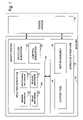
- FIG. 1is a schematic block diagram of a machine with a fast-acting safety system.
- FIG. 2is a schematic diagram of an exemplary safety system in the context of a machine having a circular blade.
- FIG. 3shows a possible configuration of a fusible member.
- FIG. 4shows various embodiments of fusible members.
- FIG. 5shows an embodiment of a firing subsystem used with a machine having a fast-acting safety system.
- FIG. 6shows another embodiment of a firing subsystem.
- FIG. 7shows still another embodiment of a firing subsystem.
- FIG. 8shows a firing subsystem mounted on a printed circuit board.
- FIG. 9shows a sectional view of electrodes used in a firing subsystem.
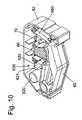
- FIG. 10shows a firing subsystem in a cartridge used with a machine having a fast-acting safety system.
- FIG. 11shows two electrodes contacting a fusible member.
- FIG. 12shows a graph of data concerning the time to burn a wire under various conditions.
- FIG. 13also shows a graph of data concerning the time to burn a wire under various conditions.
- FIG. 14also shows a graph of data concerning the time to burn a wire under various conditions.
- FIG. 15also shows a graph of data concerning the time to burn a wire under various conditions.
- FIG. 16shows an explosive charge that can be triggered by a firing subsystem.
- Machine 10may be any of a variety of different machines adapted for cutting workpieces, such as wood, including a table saw, miter saw (chop saw), radial arm saw, circular saw, band saw, jointer, planer, etc.
- Machine 10includes an operative structure 12 having a cutting tool 14 and a motor assembly 16 adapted to drive the cutting tool.
- Machine 10also includes a safety system 18 configured to minimize the potential of a serious injury to a person using machine 10 .
- Safety system 18is adapted to detect the occurrence of one or more dangerous conditions during use of machine 10 . If such a dangerous condition is detected, safety system 18 is adapted to engage operative structure 12 to limit any injury to the user caused by the dangerous condition.
- Machine 10also includes a suitable power source 20 to provide power to operative structure 12 and safety system 18 .
- Power source 20may be an external power source such as line current, or an internal power source such as a battery.
- power source 20may include a combination of both external and internal power sources.
- power source 20may include two or more separate power sources, each adapted to power different portions of machine 10 .
- operative structure 12may take any one of many different forms, depending on the type of machine 10 .
- operative structure 12may include a stationary housing configured to support motor assembly 16 in driving engagement with cutting tool 14 .
- operative structure 12may include a movable structure configured to carry cutting tool 14 between multiple operating positions.
- operative structure 12may include one or more transport mechanisms adapted to convey a workpiece toward and/or away from cutting tool 14 .
- Motor assembly 16includes one or more motors adapted to drive cutting tool 14 .
- the motorsmay be either directly or indirectly coupled to the cutting tool, and may also be adapted to drive workpiece transport mechanisms.
- Cutting tool 14typically includes one or more blades or other suitable cutting implements that are adapted to cut or remove portions from the workpieces.
- the particular form of cutting tool 14will vary depending upon the various embodiments of machine 10 .
- cutting tool 14will typically include one or more circular rotating blades having a plurality of teeth disposed along the perimetrical edge of the blade.
- the cutting tooltypically includes a plurality of radially spaced-apart blades.
- the cutting toolincludes an elongate, circuitous tooth-edged band.
- Safety system 18includes a detection subsystem 22 , a reaction subsystem 24 and a control subsystem 26 .
- Control subsystem 26may be adapted to receive inputs from a variety of sources including detection subsystem 22 , reaction subsystem 24 , operative structure 12 and motor assembly 16 .
- the control subsystemmay also include one or more sensors adapted to monitor selected parameters of machine 10 .
- control subsystem 26typically includes one or more instruments operable by a user to control the machine.
- the control subsystemis configured to control machine 10 in response to the inputs it receives.
- Detection subsystem 22is configured to detect one or more dangerous, or So triggering, conditions during use of machine 10 .
- the detection subsystemmay be configured to detect that a portion of the user's body is dangerously close to, or in contact with, a portion of cutting tool 14 .
- the detection subsystemmay be configured to detect the rapid movement of a workpiece due to kickback by the cutting tool, as is described in U.S. Provisional Patent Application Ser. No. 60/182,866, entitled “Fast-Acting Safety Stop,” filed Feb. 16, 2000 by SD3, LLC, the disclosure of which is herein incorporated by reference.
- detection subsystem 22may inform control subsystem 26 of the dangerous condition, which then activates reaction subsystem 24 .
- the detection subsystemmay be adapted to activate the reaction subsystem directly.
- reaction subsystem 24is configured to engage operative structure 12 quickly to prevent serious injury to the user. It will be appreciated that the particular action to be taken by reaction subsystem 24 will vary depending on the type of machine 10 and/or the dangerous condition that is detected. For example, reaction subsystem 24 may be configured to do one or more of the following: stop the movement of cutting tool 14 , disconnect motor assembly 16 from power source 20 , place a barrier between the cutting tool and the user, or retract the cutting tool from its operating position, etc. The reaction subsystem may be configured to take a combination of steps to protect the user from serious injury. Placement of a barrier between the cutting tool and teeth is described in more detail in U.S. Provisional Patent Application Ser. No.
- 60/225,206entitled “Cutting Tool Safety System,” filed Aug. 14, 2000 by SD3, LLC, the disclosure of which is herein incorporated by reference. Retraction of the cutting tool from its operating position is described in more detail in U.S. Provisional Patent Application Ser. No. 60/225,089, entitled “Retraction System For Use In Power Equipment,” also filed Aug. 14, 2000 by SD3, LLC., the disclosure of which is herein incorporated by reference.
- reaction subsystem 24typically will vary depending on which action(s) are taken.
- reaction subsystem 24is configured to stop the movement of cutting tool 14 and includes a brake mechanism 28 , a biasing mechanism 30 , a restraining mechanism 32 , and a release mechanism 34 .
- Brake mechanism 28is adapted to engage operative structure 12 under the urging of biasing mechanism 30 .
- restraining mechanism 32holds the brake mechanism out of engagement with the operative structure.
- the brake mechanismupon receipt of an activation signal by reaction subsystem 24 , the brake mechanism is released from the restraining mechanism by release mechanism 34 , whereupon, the brake mechanism quickly engages at least a portion of the operative structure to bring the cutting tool to a stop.
- FIG. 2one example of the many possible implementations of safety system 18 is shown.
- System 18is configured to engage an operative structure having a cutting tool in the form of a circular blade 40 mounted on a rotating shaft or arbor 42 .
- Blade 40includes a plurality of cutting teeth (not shown) disposed around the outer edge of the blade.
- braking mechanism 28is adapted to engage the teeth of blade 40 and stop the rotation of the blade.
- detection subsystem 22is adapted to detect the dangerous condition of the user coming into contact with blade 40 .
- the detection subsystemincludes a sensor assembly, such as contact detection plates 44 and 46 , capacitively coupled to blade 40 to detect any contact between the user's body and the blade.
- the blade, or some larger portion of cutting tool 14is electrically isolated from the remainder of machine 10 .
- detection subsystem 22may include a different sensor assembly configured to detect contact in other ways, such as optically, resistively, etc.
- the detection subsystemis adapted to transmit a signal to control subsystem 26 when contact between the user and the blade is detected.
- Various exemplary embodiments and implementations of detection subsystem 22are described in more detail in U.S. Provisional Patent Application Ser. No.
- 60/225,200entitled “Contact Detection System For Power Equipment,” filed Aug. 14, 2000 by SD3, LLC, and U.S. Provisional Patent Application Ser. No. 60/225,211, entitled “Apparatus And Method For Detecting Dangerous Conditions In Power Equipment,” filed Aug. 14, 2000 by SD3, LLC, the disclosures of which are herein incorporated by reference.
- Control subsystemincludes one or more instruments 48 that are operable by a user to control the motion of blade 40 .
- Instruments 48may include start/stop switches, speed controls, direction controls, etc.
- Control subsystem 26also includes a logic controller 50 connected to receive the user's inputs via instruments 48 .
- Logic controller 50is also connected to receive a contact detection signal from detection subsystem 22 . Further, the logic controller may be configured to receive inputs from other sources (not shown) such as blade motion sensors, workpiece sensors, etc. In any event, the logic controller is configured to control operative structure 12 in response to the user's inputs through instruments 48 .
- control subsystem 26Various exemplary embodiments and implementations of control subsystem 26 are described in more detail in U.S. Provisional Patent Application Ser. No. 60/225,059, entitled “Logic Control For Fast Acting Safety System,” filed Aug. 14, 2000 by SD3, LLC, and U.S. Provisional Patent Application Ser. No. 60/225,094, entitled “Motion Detecting System For Use In Safety System For Power Equipment,” filed Aug. 14, 2000 by SD3, LLC, the disclosures of which are herein incorporated by reference.
- brake mechanism 28includes a pawl 60 mounted adjacent the edge of blade 40 and selectively moveable to engage and grip the teeth of the blade.
- Pawl 60may be constructed of any suitable material adapted to engage and stop the blade.
- the pawlmay be constructed of a relatively high strength thermoplastic material such as polycarbonate, ultrahigh molecular weight polyethylene (UHMW) or Acrylonitrile Butadiene Styrene (ABS), etc., or a metal such as aluminum, etc. It will be appreciated that the construction of pawl 60 will vary depending on the configuration of blade 40 . In any event, the pawl is urged into the blade by a biasing mechanism in the form of a spring 66 .
- pawl 60is pivoted into the teeth of blade 40 . It should be understood that sliding or rotary movement of pawl 60 may also be used.
- the springis adapted to urge pawl 60 into the teeth of the blade with sufficient force to grip the blade and quickly bring it to a stop.
- a restraining memberin the form of a fusible member 70 , holds the pawl away from the edge of the blade.
- the fusible memberis constructed of a suitable material adapted to restrain the pawl against the bias of spring 66 , and also adapted to melt under a determined electrical current density. Examples of suitable materials for fusible member 70 include NiChrome wire, stainless steel wire, etc.
- the fusible memberis connected between the pawl and a contact mount 72 .
- Preferably member 70holds the pawl relatively close to the edge of the blade to reduce the distance pawl 60 must travel to engage blade 40 . Positioning the pawl relatively close to the edge of the blade reduces the time required for the pawl to engage and stop the blade.
- the pawlis held approximately 1/32-inch to 1 ⁇ 4-inch from the edge of the blade by fusible member 70 , however other pawl-to-blade spacings may also be used within the scope of the invention.
- Pawl 60is released from its unactuated, or cocked, position to engage blade 40 by a release mechanism in the form of a firing subsystem 76 .
- the firing subsystemis coupled to contact mount 72 , and is configured to melt fusible member 70 by passing a surge of electrical current through the fusible member.
- Firing subsystem 76is coupled to logic controller 50 and activated by a signal from the logic controller. When the logic controller receives a contact detection signal from detection subsystem 22 , the logic controller sends an activation signal to firing subsystem 76 , which melts fusible member 70 , thereby releasing the pawl to stop the blade.
- reaction subsystem 24are described in more detail in U.S. Provisional Patent Application Ser. No.
- safety system 18includes a replaceable cartridge 80 having a housing 82 .
- Pawl 60 , spring 66 , fusible member 70 and contact mount 72are all mounted within housing 82 .
- other portions of safety system 18may be mounted within the housing.
- safety system 18may be replaced separately or reused as appropriate.
- Various exemplary embodiments and implementations of a safety system using a replaceable cartridgeare described in more detail in U.S. Provisional Patent Application Ser. No. 60/225,201, entitled “Replaceable Brake Mechanism For Power Equipment,” filed Aug. 14, 2000 by SD3, LLC, and U.S. Provisional Patent Application Ser. No. 60/225,212, entitled “Brake Positioning System,” filed Aug. 14, 2000 by SD3, LLC, the disclosures of which are herein incorporated by reference.
- a fusible membersuch as member 70 shown in FIG. 2
- a fusible memberwill be used to restrain some element or action, such as to hold a brake or pawl away from a blade, as explained above.
- a fusible membermay take different forms, but typically is a wire that will melt when a given amount of electrical current is passed through the wire, also as explained above. Once the wire melts, the brake or pawl is released to stop the blade.
- the fusible memberWhen a pawl is used as a brake, the fusible member may be attached between the pawl and an anchor or mount, such as contact mount 72 shown in FIG. 2 , to prevent the pawl from moving into the blade.
- the pawlis biased by a spring toward the blade, so the pawl constantly pulls against the fusible member. Therefore, the fusible member should have a high tensile strength to bear the constant pull of the pawl and to prevent the fusible member from accidentally breaking. Additionally, the fusible member should have a high tensile strength so that the strength is maximized relative to the heat that is required to melt the member. Fusible members with high resistance are also preferred because of the more rapid heat build up for a given current.
- the size of the fusible memberwill depend, at least partially on the force required to restrain the spring. In general, greater spring forces are desirable to increase the speed and force with which the pawl contacts the blade. Where more pressure is required, a larger diameter fusible member may be needed, thereby requiring a larger amount of current to melt the fusible member. A greater amount of current, in turn, may require a firing system with more expensive electronic components. Thus, a safety system using a fusible member to release a brake or pawl must consider factors such as the amount of force applied to the fusible member and the size of the fusible member.
- fusible member 70is wire that has a tensile strength sufficient hold the pawl against the force of the spring.
- the fusible membermay be a 0.010-inch nichrome wire or a steel strand, and the spring may have a spring force of between approximately 5 and 25 pounds.
- the fusible memberis generally less than about 1 to 3 inches in length, and is wrapped around contact mount 72 .
- Contact mount 72is often generally circular in cross-section so that it does not present any edges that would concentrate stress to a specific section of the fusible member.
- a contact mountmay include an edge to focus stress at a desired section of the fusible member.
- the contact mountmay take many forms. It may be a stud or projection around which a fusible member is wrapped, it may be a screw with a radial hole through which the fusible member is threaded so that the screw can be turned to wrap the fusible member around the screw, it may be clamps, or it may be some other structure.
- mount 72includes a break region or gap of about 0.010 to 0.5-inch (or less) between halves of the mount. Current flows from one half of the mount, through the fusible member, to the other half of the mount and then to ground.
- the short break regionis beneficial to focus the power to a small region to help melt the fusible member.
- the two halves of the mountmay be thought of as two closely spaced electrodes, where the electrodes also serve as mounts for the fusible member. When electrodes also act as mounts, they must be strong enough to support the load of the fusible member.
- contact mount 72may be an anchor, and electrodes may be positioned against fusible member 70 between mount 72 and pawl 60 .
- the fusible membercan be arranged in many alternative ways within the scope of the invention.
- one loop of wirecan be attached to a contact stud and the opposite loop attached to a grounded stud. If the middle of the wire is placed over the end of the spring adjacent the pawl, the spring will be released when the wire is melted. In this arrangement, the current to melt the fusible member travels only from the contact stud, through the fusible member and into the grounded stud.
- a wire with a relatively low tensile strengthmay be used to hold a pawl against a large spring force by looping the wire so that different portions of the wire work together to hold the pawl.
- a wiremay be looped in the configuration of the letter “M” or “W”, as shown in FIG. 3 .
- fusible member 70is fastened at one end to anchor 600 . From there the fusible member wraps around a first post 601 on one side of pawl 60 , then around mount 602 , then around a second post 603 on the opposite side of the pawl, after which the fusible member is fastened to second anchor 604 .
- the sections of the fusible member between anchor 600 and post 601 , between post 601 and mount 602 , between mount 602 and post 603 , and between post 603 and anchor 604act like four separate strands that together hold the pawl away from the blade.
- a fusible member with tensile load strength of 30 poundsmay hold a pawl biased toward the blade with a force of up to 120 pounds.
- mount 602is configured to pass a surge of electrical current through a portion of the fusible member to melt the member. The fusible member then breaks apart at mount 602 and releases the pawl. This embodiment allows for the use of a fusible member with a relatively small diameter that may be melted with less current.
- a fusible memberwill be used to hold a two-stage linkage, trap or compound release.
- the linkage or compound releasewould restrain some action or hold some element such as a pawl.
- the fusible membereffectively restrains an action or holds an element.
- Using a linkage or a compound releaseprovides a mechanical advantage that allows the system to use a fusible member with a smaller diameter and lesser tensile strength to hold forces up to hundreds of pounds or more. This may allow use of a smaller fusible wire that can be melted more quickly and/or with a smaller current surge.
- Various linkages and compound releasesare described in more detail in U.S. Provisional Patent Application Ser. No. 60/225,170, titled “Spring-Biased Brake Mechanism for Power Equipment,” filed Aug. 14, 2000 by SD3, LLC, the disclosure of which is herein incorporated by reference.
- the fusible memberalso may be formed from a wire overmolded with end caps or crimp blocks to establish a given length. Overmolding the ends of a wire with caps or crimp blocks provides an effective way to grip and hold the wire.
- FIG. 4shows three such fusible members.
- a wire 605is doubled back, and both ends of the wire are secured in loop 606 .
- Loop 606is a molded plastic element, and wire 605 is crimped or kinked at its ends 607 to keep the wire from breaking free of the loop. Loop 606 would typically be molded or pressed over the ends of the wire.
- Wire 605may extend around electrodes, and loop 606 may extend over a pin on a pawl or a pin in a compound release.
- the second fusible member shown in FIG. 4is similar to the one just described, except that it has two loops, one at each end of the wire. As mentioned, the ends of the wire are crimped or kinked to secure the wire to the loops and to prevent the wire from being pulled away from loops.
- Another wire 608is also shown in FIG. 4 , having caps 609 molded over the ends of the wire.
- the capsmay be used to secure the wire in some embodiments.
- Fusible members like those shown in FIG. 4would be advantageous in a system employing cartridge 82 because the cartridge could simply be reloaded with a new fusible member after firing, and the fusible member would fit in the cartridge because it is of a given length and construction.
- fusible membersmay be configured in numerous ways to hold a pawl or brake, and that the specific embodiments described simply illustrate possible ways.
- the fusible membersthemselves also may take different forms, such as a wire or a foil sheet.
- the fusible memberis connected to a firing system 76 that produces a sudden current surge to melt the fusible member in response to an output signal from the contact detection system.
- a firing system 76that produces a sudden current surge to melt the fusible member in response to an output signal from the contact detection system.
- approximately 20–100 Ampsare required to ensure complete and rapid melting.
- firing system 76is illustrated in FIG. 5 .
- That exemplary embodimentincludes one or more charge storage devices that are discharged through the fusible member in response to an output signal from the control subsystem.
- the output signal from the control subsystemis dependant on detection of contact between the user and a blade, as explained above.
- the use of charge storage devicesobviates the need for a large current supply to melt the fusible member. It will be appreciated, however, that a current supply may be used instead of charge storage devices. Alternatively, other devices may be used to supply the necessary current, including a silicon-controlled rectifier or triac connected to a power supply line.
- the firing system shown in FIG. 5includes a pair of relatively high-current transistors 610 coupled to pass the current stored in the storage devices to fusible member 70 .
- Transistors 610are switched on by the output signal from control subsystem 26 . As illustrated in FIG. 5 , the output signal from control subsystem 26 is connected to the gates of transistors 610 . Any suitable transistors may be used, such as IRFZ40 MOSFET transistors, which are well known in the art.
- the transistorsare connected in parallel between charge storage devices 611 and fusible member 70 .
- charge storage devices 611are in the form of a 75,000 ⁇ F capacitor bank.
- a 100-ohm resistor 612 connected to a 24-volt supply voltageestablishes and maintains the charge on the capacitor bank.
- transistors 610allow the charge stored in the capacitor bank to pass through the fusible member.
- the sudden release of the charge stored in the capacitor bankheats the fusible member to its melting point in approximately 1 to 5 ms.
- one or more of the transistorsmay be replaced by other switching devices such as SCR's.
- One advantage of using stored charge to fuse the fusible memberis that the firing system does not rely on the capacity of line power or the phase of the line voltage.
- FIG. 6shows an alternative embodiment of firing system 76 .
- the alternative firing circuitincludes fusible member 70 connected between a high voltage supply HV and an SCR 613 , such as an NTE 5552 SCR.
- the gate terminal of the SCRis connected to control subsystem 26 .
- Control subsystem 26turns on SCR 613 by supplying approximately 40 mA of current, thereby allowing the high voltage supply HV to discharge to ground through fusible member 70 .
- the SCROnce the SCR is switched on, it will continue to conduct as long as the current through fusible member 70 remains above the holding current of approximately 40 mA, even if the current to the gate terminal is removed. Thus, the SCR will conduct current through the fusible member until the fusible member is melted or the high voltage source is removed.
- HVhigh voltage
- FIG. 7shows yet another embodiment of firing system 76 .
- This embodimentincludes a fusible member 70 connected between a 390 ⁇ F capacitor, identified by reference number 620 , and a TYN410 SCR, identified by reference number 621 .
- the capacitor 620may range in value from approximately 100 ⁇ F to 5000 ⁇ F.
- Capacitor 620is connected between a high voltage charging line 622 (from a buck-boost charger, for example), which charges the capacitor to approximately 180–200 volts, and ground.
- the gate terminal of the SCRis connected to the control subsystem at 623 .
- a signal from the control subsystem at 623turns on SCR 621 , allowing the capacitor to discharge to ground through fusible member 70 .
- the capacitoris believed to provide a pulse of approximately 1000 to 1500 amps.
- Firing system 76also includes a 1 k resistor 624 connected between the gate of the SCR and ground to hold the signal at 623 to ground until a signal from the control subsystem draws it up so that the firing system is not triggered by noise.
- a sense line 625is connected between SCR 621 and fusible member 70 so that the control system can monitor the charge on capacitor 620 to insure that the capacitor is charged and functioning. Connecting sense line 625 downstream from fusible member 70 relative to capacitor 620 allows the control system to check the capacitor through the fusible member, which means that the control system also checks that fusible member 70 is intact and functioning. It should be noted that the sense line could also be used to charge the capacitor.
- FIG. 8shows a firing system 76 assembled on a printed circuit board 630 .
- the firing systemis similar to the circuit shown in FIG. 7 , and includes capacitor 620 and SCR 621 .
- a socket 631is associated with the printed circuit board so that the circuit can be connected to the control system, sensor line and power supply.
- a contact mount 632made from spaced apart electrodes 634 and 636 , is mounted on the printed circuit board.
- a fusible memberextends around the contact mount in use.
- FIG. 9A top, sectional view of contact mount 632 and electrodes 634 and 636 is shown in FIG. 9 , and fusible member 70 is wrapped over the electrodes.
- the electrodesare constructed with a small gap 640 , as described above, and it is at that gap that the fusible member breaks or burns when current passes from one electrode to the other through the fusible member.
- Contact mount 632is configured to fit over a supporting plug, and flanges 642 help hold the mount on the plug.
- FIG. 10shows printed circuit board 630 , including capacitor 620 and SCR 621 , mounted in cartridge 82 .
- the cartridgehouses pawl 60 , spring 66 , and fusible member 70 .
- Fusible member 70restrains pawl 60 from moving outwardly by restraining the motion of compound linkage 650 .
- Fusible member 70extends around contact mount 632 .
- Contact mount 632fits over a supporting plug that is part of the cartridge housing. Fusible member 70 bums when firing system 76 on printed circuit board 630 sends a surge of current through the fusible member. Compound linkage 650 and pawl 60 are then free to move, and spring 66 quickly forces pawl 60 outwardly.
- Cartridge 82can be configured to fit into various types of power equipment, such as table saws, jointers, etc. Additionally, cartridge 82 can be “re-loaded,” or replenished with a new pawl and fusible member, and reused after the firing system has fired.
- FIG. 11shows an embodiment in which a fusible member 70 is mounted between an anchor 652 and a pawl 60 .
- Two electrodes 653 and 654contact the fusible member between the anchor and pawl, but do not support the fusible member.
- Electrodes 653 and 654may take the form of conductive traces on a printed circuit board 656 .
- the conductive tracesare formed on the surface of the printed circuit board and extend slightly above that surface, so that fusible member 70 can contact them by extending across them.
- the printed circuit boardcan be positioned so that electrodes 653 and 654 apply some pressure against fusible member 70 to insure contact with the fusible member.
- Electrodes 653 and 654are connected to a firing subsystem, as described. Of course, the configuration and orientation of electrodes 653 and 654 can vary.
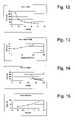
- FIGS. 12 through 15show data concerning the time it takes for a firing subsystem to burn a wire given varying factors, such as the firing system, the wire size, the load on the fusible member, etc.
- FIG. 11shows the approximate time it takes to burn a wire as the load on the wire varies.
- the wire testedwas stainless steel, ASTM 302/304, spring tempered, with a diameter of 0.010 inches and was wrapped over brass electrodes with a 0.044 inch gap.
- the firing systemused a 390 ⁇ F capacitor charged to 163 volts to burn the wire.
- This datashow that the time to burn a fusible member decreases as the load on the member increases.
- FIG. 13shows the approximate time it takes to burn a wire as the spacing between electrodes varies.
- the wire testedwas stainless steel, ASTM 302/304, spring tempered, with a diameter of 0.010-inches and was wrapped over brass electrodes.
- the firing systemused a 390 ⁇ F capacitor charged to 163 volts to burn the wire.
- the wirehad a load of 20 pounds.
- the wireburned in approximately the following times for the specified gaps: 70 ⁇ s with a 0.1 inch gap, 47 ⁇ s with a 0.044 inch gap, and 37 ⁇ s with a 0.013 inch gap. This data shows that the time to burn a fusible member decreases as the gap between electrodes decreases.
- FIG. 14shows the approximate time it takes to burn a wire as the voltage on the capacitor in the firing system varies.
- the wire testedwas stainless steel, ASTM 302/304, spring tempered, with a diameter of 0.010 inches and was wrapped over brass electrodes with a 0.044 inch gap.
- the firing systemused a 390 ⁇ F capacitor.
- the wireburned in approximately the following times for the specified voltages: 296 ⁇ s with 123 volts, 103 ⁇ s with 133 volts, 81 ⁇ s with 143 volts, 57 ⁇ s with 153 volts, 47 ⁇ s with 163 volts, 40 ⁇ s with 173 volts, and 39 ⁇ s with 183 volts.
- the wiredid not burn with voltages of only 103 ⁇ s or 113 volts. This data show that the time to burn a fusible member decreases as the voltage increases.
- FIG. 15shows the approximate time it takes to burn wires of varying sizes.
- the wires testedwere all stainless steel, ASTM 302/304, spring tempered, wires.
- the wireswere wrapped over brass electrodes with a 0.044 inch gap.
- the firing systemused a 390 ⁇ F capacitor with 163 volts.
- the wirehad a load of 40 pounds.
- the wireburned in approximately the following times for the specified diameter sizes: 18 ⁇ s with a 0.010 inch diameter, 39 ⁇ s with a 0.011 inch diameter, and 81 ⁇ s with a 0.012 inch diameter.
- a wire with a 0.013 inch diameterdid not burn. This data show that the time to burn a wire decreases as the diameter of the wire decreases.
- Firing system 76may also be used to trigger some action other than burning a fusible member.
- firing system 76can fire a small explosive charge to move a pawl.
- FIG. 16shows a relatively small, self-contained explosive charge 660 in the form of a squib or detonator that can be used to drive pawl 60 against a blade.
- An example of a suitable explosive chargeis an M-100 detonator available, for example, from Stresau Laboratory, Inc., of Spooner, Wis.
- the self-contained charge or squibfocuses the force of the explosion along the direction of movement of the pawl.
- a trigger line 662extends from the charge, at it may be connected to firing system 76 to trigger detonation.
- Explosive charge 660can be used to move pawl 60 by inserting the charge between the pawl and a stationary block 664 adjacent the charge. When the charge detonates, the pawl is pushed away from the block. A compression spring 66 is placed between the block and pawl to ensure the pawl does not bounce back from the blade when the charge is detonated. Prior to detonation, the pawl is held away from the blade by the friction-fit of the charge in both the block and pawl. However, the force created upon detonation of the charge is more than sufficient to overcome the friction fit. Alternatively, the pawl may be held away from the blade by other mechanisms such as a frangible member, gravity, a spring between the pawl and block, etc.
- Firing system 76may also trigger a DC solenoid, which can be over-driven with a current surge to create a rapid displacement, a pressurized air or gas cylinder to supply the pressure in place of the spring or charge, or an electromagnet to either repel the pawl against the blade or to release a spring-loaded pawl toward the blade.
- a DC solenoidwhich can be over-driven with a current surge to create a rapid displacement
- a pressurized air or gas cylinderto supply the pressure in place of the spring or charge
- an electromagnetto either repel the pawl against the blade or to release a spring-loaded pawl toward the blade.
- the present inventionis applicable to power equipment, and specifically to firing subsystems used in power equipment to trigger or release some action.
- the inventionis particularly applicable to woodworking equipment such as table saws, miter saws, band saws, circular saws, jointers, etc.
- the firing subsystems described aboveprovide effective systems to rapidly trigger or release an action upon the occurrence and detection of a predetermined event.
- the systemscan be used to restrain some element or action until the occurrence and detection of the predetermined event.
- the systemsare manufacturable, and can be implemented with standard components.
Landscapes
- Engineering & Computer Science (AREA)
- Life Sciences & Earth Sciences (AREA)
- Mechanical Engineering (AREA)
- General Engineering & Computer Science (AREA)
- Wood Science & Technology (AREA)
- Forests & Forestry (AREA)
- Emergency Protection Circuit Devices (AREA)
Abstract
Description
Claims (18)
Priority Applications (31)
| Application Number | Priority Date | Filing Date | Title |
|---|---|---|---|
| US09/929,240US7100483B2 (en) | 2000-08-14 | 2001-08-13 | Firing subsystem for use in a fast-acting safety system |
| US10/047,066US6945148B2 (en) | 2000-09-29 | 2002-01-14 | Miter saw with improved safety system |
| US10/050,085US20020056349A1 (en) | 2000-09-29 | 2002-01-14 | Miter saw with improved safety system |
| US10/051,782US6877410B2 (en) | 2000-09-29 | 2002-01-15 | Miter saw with improved safety system |
| US10/053,390US7377199B2 (en) | 2000-09-29 | 2002-01-16 | Contact detection system for power equipment |
| US10/052,274US6826988B2 (en) | 2000-09-29 | 2002-01-16 | Miter saw with improved safety system |
| US10/052,806US6880440B2 (en) | 2000-09-29 | 2002-01-16 | Miter saw with improved safety system |
| US10/052,273US6813983B2 (en) | 2000-09-29 | 2002-01-16 | Power saw with improved safety system |
| US10/052,705US6994004B2 (en) | 2000-09-29 | 2002-01-16 | Table saw with improved safety system |
| US10/984,643US8061245B2 (en) | 2000-09-29 | 2004-11-08 | Safety methods for use in power equipment |
| US11/190,111US7357056B2 (en) | 2000-09-29 | 2005-07-25 | Cutting tool safety system |
| US11/218,356US7621205B2 (en) | 1999-10-01 | 2005-09-02 | Band saw with safety system |
| US11/348,580US20060123964A1 (en) | 2000-09-29 | 2006-02-06 | Table saw with improved safety system |
| US11/401,050US7788999B2 (en) | 1999-10-01 | 2006-04-10 | Brake mechanism for power equipment |
| US11/401,774US7525055B2 (en) | 1999-10-01 | 2006-04-11 | Switch box for power tools with safety systems |
| US11/445,548US7347131B2 (en) | 1999-10-01 | 2006-06-02 | Miter saw with improved safety system |
| US11/542,938US20070028733A1 (en) | 1999-10-01 | 2006-10-02 | Safety methods for use in power equipment |
| US12/154,675US7617752B2 (en) | 2000-09-29 | 2008-05-23 | Contact detection system for power equipment |
| US12/313,162US7789002B2 (en) | 2000-09-29 | 2008-11-17 | Table saw with improved safety system |
| US12/590,924US8186255B2 (en) | 2000-09-29 | 2009-11-16 | Contact detection system for power equipment |
| US12/800,607US7895927B2 (en) | 1999-10-01 | 2010-05-19 | Power equipment with detection and reaction systems |
| US12/806,836US8196499B2 (en) | 1999-10-01 | 2010-08-20 | Power equipment with detection and reaction systems |
| US12/806,830US8191450B2 (en) | 2000-08-14 | 2010-08-20 | Power equipment with detection and reaction systems |
| US12/806,829US9522476B2 (en) | 1999-10-01 | 2010-08-20 | Power equipment with detection and reaction systems |
| US12/807,146US8291797B2 (en) | 1999-10-01 | 2010-08-27 | Table saw with improved safety system |
| US12/807,147US8402869B2 (en) | 1999-10-01 | 2010-08-27 | Brake mechanism for power equipment |
| US13/442,290US8408106B2 (en) | 1999-10-01 | 2012-04-09 | Method of operating power equipment with detection and reaction systems |
| US13/854,270US20170190012A9 (en) | 1999-10-01 | 2013-04-01 | Power equipment with detection and reaction systems |
| US15/357,928US9969014B2 (en) | 1999-10-01 | 2016-11-21 | Power equipment with detection and reaction systems |
| US15/362,388US9878380B2 (en) | 1999-10-01 | 2016-11-28 | Table saw throat plates and table saws including the same |
| US15/935,395US10335972B2 (en) | 1999-10-01 | 2018-03-26 | Table Saws |
Applications Claiming Priority (15)
| Application Number | Priority Date | Filing Date | Title |
|---|---|---|---|
| US22520000P | 2000-08-14 | 2000-08-14 | |
| US22505900P | 2000-08-14 | 2000-08-14 | |
| US22508900P | 2000-08-14 | 2000-08-14 | |
| US22505700P | 2000-08-14 | 2000-08-14 | |
| US22521000P | 2000-08-14 | 2000-08-14 | |
| US22521200P | 2000-08-14 | 2000-08-14 | |
| US22509400P | 2000-08-14 | 2000-08-14 | |
| US22521100P | 2000-08-14 | 2000-08-14 | |
| US22505800P | 2000-08-14 | 2000-08-14 | |
| US22517000P | 2000-08-14 | 2000-08-14 | |
| US22520600P | 2000-08-14 | 2000-08-14 | |
| US22516900P | 2000-08-14 | 2000-08-14 | |
| US22520100P | 2000-08-14 | 2000-08-14 | |
| US22505600P | 2000-08-14 | 2000-08-14 | |
| US09/929,240US7100483B2 (en) | 2000-08-14 | 2001-08-13 | Firing subsystem for use in a fast-acting safety system |
Related Parent Applications (7)
| Application Number | Title | Priority Date | Filing Date |
|---|---|---|---|
| US09/929,242ContinuationUS7509899B2 (en) | 1999-10-01 | 2001-08-13 | Retraction system for use in power equipment |
| US09/929,241Continuation-In-PartUS7024975B2 (en) | 1999-10-01 | 2001-08-13 | Brake mechanism for power equipment |
| US09/929,241ContinuationUS7024975B2 (en) | 1999-10-01 | 2001-08-13 | Brake mechanism for power equipment |
| US09/929,227ContinuationUS7308843B2 (en) | 1999-10-01 | 2001-08-13 | Spring-biased brake mechanism for power equipment |
| US09/929,425ContinuationUS7137326B2 (en) | 1999-10-01 | 2001-08-13 | Translation stop for use in power equipment |
| US09/929,238Continuation-In-PartUS20020017179A1 (en) | 1999-10-01 | 2001-08-13 | Miter saw with improved safety system |
| US09/929,238ContinuationUS20020017179A1 (en) | 1999-10-01 | 2001-08-13 | Miter saw with improved safety system |
Related Child Applications (22)
| Application Number | Title | Priority Date | Filing Date |
|---|---|---|---|
| US09/929,221ContinuationUS7284467B2 (en) | 1999-10-01 | 2001-08-13 | Apparatus and method for detecting dangerous conditions in power equipment |
| US09/929,241Continuation-In-PartUS7024975B2 (en) | 1999-10-01 | 2001-08-13 | Brake mechanism for power equipment |
| US09/929,241ContinuationUS7024975B2 (en) | 1999-10-01 | 2001-08-13 | Brake mechanism for power equipment |
| US09/929,238Continuation-In-PartUS20020017179A1 (en) | 1999-10-01 | 2001-08-13 | Miter saw with improved safety system |
| US09/929,238ContinuationUS20020017179A1 (en) | 1999-10-01 | 2001-08-13 | Miter saw with improved safety system |
| US09/929,226ContinuationUS6920814B2 (en) | 1999-10-01 | 2001-08-13 | Cutting tool safety system |
| US10/050,085Continuation-In-PartUS20020056349A1 (en) | 1999-10-01 | 2002-01-14 | Miter saw with improved safety system |
| US10/047,066Continuation-In-PartUS6945148B2 (en) | 1999-10-01 | 2002-01-14 | Miter saw with improved safety system |
| US10/051,782Continuation-In-PartUS6877410B2 (en) | 1999-10-01 | 2002-01-15 | Miter saw with improved safety system |
| US10/052,273Continuation-In-PartUS6813983B2 (en) | 2000-09-29 | 2002-01-16 | Power saw with improved safety system |
| US10/052,806Continuation-In-PartUS6880440B2 (en) | 1999-10-01 | 2002-01-16 | Miter saw with improved safety system |
| US10/052,274Continuation-In-PartUS6826988B2 (en) | 2000-09-29 | 2002-01-16 | Miter saw with improved safety system |
| US10/053,390Continuation-In-PartUS7377199B2 (en) | 1999-10-01 | 2002-01-16 | Contact detection system for power equipment |
| US10/052,705Continuation-In-PartUS6994004B2 (en) | 1999-10-01 | 2002-01-16 | Table saw with improved safety system |
| US10/984,643ContinuationUS8061245B2 (en) | 1999-10-01 | 2004-11-08 | Safety methods for use in power equipment |
| US11/190,111ContinuationUS7357056B2 (en) | 1999-10-01 | 2005-07-25 | Cutting tool safety system |
| US11/218,356ContinuationUS7621205B2 (en) | 1999-10-01 | 2005-09-02 | Band saw with safety system |
| US11/401,050ContinuationUS7788999B2 (en) | 1999-10-01 | 2006-04-10 | Brake mechanism for power equipment |
| US11/401,774ContinuationUS7525055B2 (en) | 1999-10-01 | 2006-04-11 | Switch box for power tools with safety systems |
| US11/445,548ContinuationUS7347131B2 (en) | 1999-10-01 | 2006-06-02 | Miter saw with improved safety system |
| US12/800,607ContinuationUS7895927B2 (en) | 1999-10-01 | 2010-05-19 | Power equipment with detection and reaction systems |
| US12/806,830ContinuationUS8191450B2 (en) | 1999-10-01 | 2010-08-20 | Power equipment with detection and reaction systems |
Publications (2)
| Publication Number | Publication Date |
|---|---|
| US20020020263A1 US20020020263A1 (en) | 2002-02-21 |
| US7100483B2true US7100483B2 (en) | 2006-09-05 |
Family
ID=27585535
Family Applications (1)
| Application Number | Title | Priority Date | Filing Date |
|---|---|---|---|
| US09/929,240Expired - LifetimeUS7100483B2 (en) | 1999-10-01 | 2001-08-13 | Firing subsystem for use in a fast-acting safety system |
Country Status (1)
| Country | Link |
|---|---|
| US (1) | US7100483B2 (en) |
Cited By (63)
| Publication number | Priority date | Publication date | Assignee | Title |
|---|---|---|---|---|
| US20020017176A1 (en)* | 2000-08-14 | 2002-02-14 | Gass Stephen F. | Detection system for power equipment |
| US7359174B2 (en) | 2000-08-14 | 2008-04-15 | Sd3, Llc | Motion detecting system for use in a safety system for power equipment |
| US20080203716A1 (en)* | 2007-02-27 | 2008-08-28 | Autoliv Asp, Inc. | Occupant restraint system |
| US7421315B2 (en) | 2001-11-13 | 2008-09-02 | Sd3, Llc | Detection system for power equipment |
| US20090065225A1 (en)* | 2007-09-07 | 2009-03-12 | Black & Decker Inc. | Switchable anti-lock control |
| US7525055B2 (en) | 1999-10-01 | 2009-04-28 | Sd3, Llc | Switch box for power tools with safety systems |
| US7591210B2 (en) | 2001-07-02 | 2009-09-22 | Sd3, Llc | Discrete proximity detection system |
| US7628101B1 (en) | 2006-03-13 | 2009-12-08 | Power Tool Institute | Pyrotechnic drop mechanism for power tools |
| US7712403B2 (en) | 2001-07-03 | 2010-05-11 | Sd3, Llc | Actuators for use in fast-acting safety systems |
| US7788999B2 (en) | 1999-10-01 | 2010-09-07 | Sd3, Llc | Brake mechanism for power equipment |
| US7827893B2 (en) | 2003-12-31 | 2010-11-09 | Sd3, Llc | Elevation mechanism for table saws |
| US7836804B2 (en) | 2003-08-20 | 2010-11-23 | Sd3, Llc | Woodworking machines with overmolded arbors |
| US7866239B2 (en) | 2003-12-31 | 2011-01-11 | Sd3, Llc | Elevation mechanism for table saws |
| US20110048196A1 (en)* | 2009-08-26 | 2011-03-03 | Credo Technology Corporation | Table saw with dropping blade |
| US20110048207A1 (en)* | 2009-08-26 | 2011-03-03 | Credo Technology Corporation | Table saw with linkage drop system |
| US20110048189A1 (en)* | 2009-08-26 | 2011-03-03 | Credo Technology Corporation | Table saw with positive locking mechanism |
| US20110048193A1 (en)* | 2009-08-26 | 2011-03-03 | Credo Technology Corporation | Table saw with pressure operated actuator |
| US20110048206A1 (en)* | 2009-08-26 | 2011-03-03 | Credo Technology Corporation | Table saw with alignment plate |
| US20110048190A1 (en)* | 2009-08-26 | 2011-03-03 | Credo Technology Corporation | Table saw with belt stop |
| US20110048205A1 (en)* | 2009-08-26 | 2011-03-03 | Credo Technology Corporation | Table saw with dust shield |
| US20110048194A1 (en)* | 2009-08-26 | 2011-03-03 | Credo Technology Corporation | Table saw with reset mechanism |
| US20110048191A1 (en)* | 2009-08-26 | 2011-03-03 | Credo Technology Corporation | Table saw with swing arm support |
| US20110048188A1 (en)* | 2009-08-26 | 2011-03-03 | Credo Technology Corporation | Table saw with actuator module |
| US20110048192A1 (en)* | 2009-08-26 | 2011-03-03 | Credo Technology Corporation | Table saw with mechanical fuse |
| US20110048204A1 (en)* | 2009-08-26 | 2011-03-03 | Credo Technology Corporation | Table saw with actuator reset mechanism |
| US20110048195A1 (en)* | 2009-08-26 | 2011-03-03 | Credo Technology Corporation | Table saw with ratchet mechanism |
| US8008812B2 (en) | 2006-07-14 | 2011-08-30 | Aurora Office Equipment Co., Ltd. | Paper shredder control system responsive to touch-sensitive element |
| US8018099B2 (en) | 2006-07-14 | 2011-09-13 | Aurora Office Equipment Co., Ltd. | Touch-sensitive paper shredder control system |
| US8061245B2 (en) | 2000-09-29 | 2011-11-22 | Sd3, Llc | Safety methods for use in power equipment |
| US8087599B2 (en) | 2009-05-07 | 2012-01-03 | Aurora Office Equipment Co., Ltd. | Anti-paper jam protection device for shredders |
| US8146845B2 (en) | 2008-08-06 | 2012-04-03 | Aurora Office Equipment Co., Ltd. Shanghai | Automatic shredder without choosing the number of paper to be shredded |
| US8201766B2 (en) | 2008-08-19 | 2012-06-19 | Aurora Office Equipment Co., Ltd. | Pins or staples removable structure of automatic shredders |
| US8534174B2 (en) | 2010-09-27 | 2013-09-17 | Power Tool Institute | Pyrotechnic actuator and power cutting tool with safety reaction system having such pyrotechnic actuator |
| US8708260B2 (en) | 2011-08-08 | 2014-04-29 | Aurora Office Equipment Co., Ltd. | Depowered standby paper shredder and method |
| US8723468B2 (en) | 2011-04-28 | 2014-05-13 | Aurora Office Equipment Co., Ltd. | Cooled motor |
| US8919231B2 (en) | 2008-11-19 | 2014-12-30 | Power Tool Institute | Safety mechanisms for power tools |
| US9511429B2 (en) | 2013-03-15 | 2016-12-06 | Robert BoschTool Corporation | Blade drop for power device and method of manufacturing thereof |
| US9517516B2 (en) | 2013-03-14 | 2016-12-13 | Robert Bosch Tool Corporation | Blade drop power tool with dust management |
| US9687922B2 (en) | 2015-03-12 | 2017-06-27 | Robert Bosch Tool Corporation | Power tool with cammed throat plate |
| US9724840B2 (en) | 1999-10-01 | 2017-08-08 | Sd3, Llc | Safety systems for power equipment |
| US9849527B2 (en) | 2015-03-12 | 2017-12-26 | Robert Bosch Tool Corporation | Power tool with lightweight actuator housing |
| US9868166B2 (en) | 2015-03-12 | 2018-01-16 | Robert Bosch Tool Corporation | Power tool with pyrotechnic lockout |
| US9868167B2 (en) | 2015-03-12 | 2018-01-16 | Robert Bosch Tool Corporation | Power tool with drop arm orbit bracket |
| US9914239B2 (en) | 2015-03-12 | 2018-03-13 | Robert Bosch Tool Corporation | User interface system in a table saw |
| US9927796B2 (en) | 2001-05-17 | 2018-03-27 | Sawstop Holding Llc | Band saw with improved safety system |
| US9969015B2 (en) | 2015-03-12 | 2018-05-15 | Robert Bosch Tool Corporation | Power tool with protected coupling plate |
| US10071432B2 (en) | 2015-03-12 | 2018-09-11 | Robert Bosch Tool Corporation | Power tool with arbor lock |
| US10099399B2 (en) | 2015-03-12 | 2018-10-16 | Robert Bosch Tool Corporation | Object proximity detection in a saw |
| US10105863B2 (en) | 2015-03-12 | 2018-10-23 | Robert Bosch Tool Corporation | System and method for object and operator profiling in an object detection system in a saw |
| US10189098B2 (en) | 2015-03-12 | 2019-01-29 | Robert Bosch Tool Corporation | Diagnostic and maintenance operation for a saw |
| US10213853B2 (en) | 2015-03-12 | 2019-02-26 | Robert Bosch Tool Corporation | Power tool drop arm with offset ribbing |
| US10322522B2 (en) | 2015-03-12 | 2019-06-18 | Robert Bosch Tool Corporation | Electrical configuration for object detection system in a saw |
| US10369642B2 (en) | 2015-03-12 | 2019-08-06 | Robert Bosch Tool Corporation | Power tool with protected circuit board orientation |
| US10427227B2 (en) | 2015-03-12 | 2019-10-01 | Robert Bosch Tool Corporation | Drop arm reset method |
| US10493543B2 (en) | 2015-03-12 | 2019-12-03 | Robert Bosch Tool Corporation | Power tool motor with reduced electrical noise |
| US10758989B2 (en) | 2015-03-12 | 2020-09-01 | Robert Bosch Tool Corporation | System and method for sensing cable fault detection in a saw |
| US10786854B2 (en) | 2015-03-12 | 2020-09-29 | Robert Bosch Tool Corporation | Table saw with electrically isolated arbor shaft |
| US10799964B2 (en) | 2015-03-12 | 2020-10-13 | Robert Bosch Tool Corporation | Table saw with pulley alignment mechanism |
| US10821529B2 (en) | 2015-03-12 | 2020-11-03 | Robert Bosch Tool Corporation | Power tool with improved belt tensioning |
| US10981238B2 (en) | 2009-10-02 | 2021-04-20 | Sawstop Holding Llc | Actuators for power tool safety systems |
| US11085582B2 (en) | 2017-08-30 | 2021-08-10 | Milwaukee Electric Tool Corporation | Power tool having object detection |
| EP4338908A2 (en) | 2016-05-31 | 2024-03-20 | SawStop Holding LLC | Detection systems for power tools with active injury mitigation technology |
| US20240116204A1 (en)* | 2022-10-05 | 2024-04-11 | Yu-Tzu Liu | Biaxial type sawing device |
Families Citing this family (47)
| Publication number | Priority date | Publication date | Assignee | Title |
|---|---|---|---|---|
| US20030056853A1 (en) | 2001-09-21 | 2003-03-27 | Gass Stephen F. | Router with improved safety system |
| US8065943B2 (en) | 2000-09-18 | 2011-11-29 | Sd3, Llc | Translation stop for use in power equipment |
| US7231856B2 (en) | 2001-06-13 | 2007-06-19 | Sd3, Llc | Apparatus and method for detecting dangerous conditions in power equipment |
| US6877410B2 (en) | 2000-09-29 | 2005-04-12 | Sd3, Llc | Miter saw with improved safety system |
| US6994004B2 (en) | 2000-09-29 | 2006-02-07 | Sd3, Llc | Table saw with improved safety system |
| US7290472B2 (en) | 2002-01-14 | 2007-11-06 | Sd3, Llc | Miter saw with improved safety system |
| US7308843B2 (en)* | 2000-08-14 | 2007-12-18 | Sd3, Llc | Spring-biased brake mechanism for power equipment |
| US7350445B2 (en) | 2003-08-20 | 2008-04-01 | Sd3, Llc | Brake cartridge for power equipment |
| US7481140B2 (en) | 2005-04-15 | 2009-01-27 | Sd3, Llc | Detection systems for power equipment |
| US6857345B2 (en) | 2000-08-14 | 2005-02-22 | Sd3, Llc | Brake positioning system |
| US6957601B2 (en) | 2000-08-14 | 2005-10-25 | Sd3, Llc | Translation stop for use in power equipment |
| US7000514B2 (en) | 2001-07-27 | 2006-02-21 | Sd3, Llc | Safety systems for band saws |
| US6945149B2 (en) | 2001-07-25 | 2005-09-20 | Sd3, Llc | Actuators for use in fast-acting safety systems |
| US20030037651A1 (en) | 2001-08-13 | 2003-02-27 | Gass Stephen F. | Safety systems for power equipment |
| US7536238B2 (en) | 2003-12-31 | 2009-05-19 | Sd3, Llc | Detection systems for power equipment |
| US6945148B2 (en) | 2000-09-29 | 2005-09-20 | Sd3, Llc | Miter saw with improved safety system |
| US8459157B2 (en) | 2003-12-31 | 2013-06-11 | Sd3, Llc | Brake cartridges and mounting systems for brake cartridges |
| US7472634B2 (en) | 2003-08-20 | 2009-01-06 | Sd3, Llc | Woodworking machines with overmolded arbors |
| US6880440B2 (en) | 2000-09-29 | 2005-04-19 | Sd3, Llc | Miter saw with improved safety system |
| US7353737B2 (en) | 2001-08-13 | 2008-04-08 | Sd3, Llc | Miter saw with improved safety system |
| US7197969B2 (en) | 2001-09-24 | 2007-04-03 | Sd3, Llc | Logic control with test mode for fast-acting safety system |
| US7610836B2 (en)* | 2000-08-14 | 2009-11-03 | Sd3, Llc | Replaceable brake mechanism for power equipment |
| US7377199B2 (en) | 2000-09-29 | 2008-05-27 | Sd3, Llc | Contact detection system for power equipment |
| US6813983B2 (en) | 2000-09-29 | 2004-11-09 | Sd3, Llc | Power saw with improved safety system |
| US6826988B2 (en) | 2000-09-29 | 2004-12-07 | Sd3, Llc | Miter saw with improved safety system |
| CN1547521A (en)* | 2001-07-11 | 2004-11-17 | �����˺ʹ��˹�˾ | Power Tool Safety Agency |
| US6900728B2 (en)* | 2002-07-29 | 2005-05-31 | Home Depot U.S.A., Inc. | System to detect user entry into a defined danger zone |
| US20040060404A1 (en)* | 2002-09-30 | 2004-04-01 | Emerson Electric Co. | Breakaway hub for saw |
| CA2448479C (en)* | 2002-11-12 | 2009-05-05 | Makita Corporation | Power tools |
| US20040123709A1 (en)* | 2002-12-30 | 2004-07-01 | Emerson Electric Co. | System for sensing user contact with a saw blade |
| US20040194594A1 (en)* | 2003-01-31 | 2004-10-07 | Dils Jeffrey M. | Machine safety protection system |
| US7698975B2 (en)* | 2003-01-31 | 2010-04-20 | Techtronic Power Tools Technology Limited | Table saw with cutting tool retraction system |
| US6922153B2 (en) | 2003-05-13 | 2005-07-26 | Credo Technology Corporation | Safety detection and protection system for power tools |
| JP2005088248A (en)* | 2003-09-12 | 2005-04-07 | Makita Corp | Power tool |
| US7347851B1 (en) | 2004-03-09 | 2008-03-25 | Leo B Kriksunov | Needleless hypodermic jet injector apparatus and method |
| US7631822B2 (en) | 2004-09-10 | 2009-12-15 | Fellowes Inc. | Shredder with thickness detector |
| US7661614B2 (en)* | 2004-09-10 | 2010-02-16 | Fellowes Inc. | Shredder throat safety system |
| US7311276B2 (en)* | 2004-09-10 | 2007-12-25 | Fellowes Inc. | Shredder with proximity sensing system |
| WO2007009172A1 (en)* | 2005-07-18 | 2007-01-25 | Bladestop Pty Limited | Electric saw with operator protection system |
| GB2437594B (en)* | 2006-04-24 | 2010-08-11 | Acco Uk Ltd | A shredding machine |
| US20080053994A1 (en)* | 2006-08-30 | 2008-03-06 | Aurora Office Equipment Co., Ltd. Shanghai | Paper-Breaker Wastebin Structure |
| US7757982B2 (en)* | 2006-09-28 | 2010-07-20 | Fellowes, Inc. | Shredder with intelligent activation switch |
| DE102006052017B4 (en)* | 2006-11-03 | 2009-03-05 | Homag Holzbearbeitungssysteme Ag | processing machine |
| GB2451513B (en) | 2007-08-02 | 2012-04-18 | Acco Uk Ltd | A shredding machine |
| CN101543799B (en)* | 2009-04-28 | 2012-10-10 | 上海震旦办公设备有限公司 | Novel protector for paper crusher |
| ES2709072T3 (en)* | 2009-10-02 | 2019-04-15 | Sawstop Holding Llc | Electrical tool comprising a safety actuator |
| US20140331833A1 (en)* | 2013-05-13 | 2014-11-13 | Stephen F. Gass | Detection system for power equipment |
Citations (449)
| Publication number | Priority date | Publication date | Assignee | Title |
|---|---|---|---|---|
| US146886A (en) | 1874-01-27 | Improvement in sawing-machines | ||
| US162814A (en) | 1875-05-04 | Improvement in saw-guards | ||
| US261090A (en) | 1882-07-11 | Circular-saw guard | ||
| US264412A (en) | 1882-09-12 | Half to john h | ||
| US299480A (en) | 1884-05-27 | Saw-guard | ||
| US302041A (en) | 1884-07-15 | Saw-guard | ||
| US307112A (en) | 1884-10-28 | Saw-guard | ||
| US509253A (en) | 1893-11-21 | Safety-guard for rip-saws | ||
| US545504A (en) | 1895-09-03 | Saw-guard | ||
| US869513A (en) | 1907-06-17 | 1907-10-29 | Frederick C Pfeil | Saw-guard. |
| US941726A (en) | 1907-10-15 | 1909-11-30 | Charles F Pfalzgraf | Safety trip device for power-operated machines. |
| US997720A (en) | 1909-08-07 | 1911-07-11 | Othon Troupenat | Safety device for saws. |
| US1037843A (en) | 1911-10-30 | 1912-09-10 | David S Ackley | Saw-guard |
| US1050649A (en) | 1910-05-28 | 1913-01-14 | Crescent Machine Company | Saw-guard. |
| US1054558A (en) | 1912-07-29 | 1913-02-25 | Nye Company | Self-adjusting support for circular-saw and shaper guards. |
| US1074198A (en) | 1913-03-21 | 1913-09-30 | Francis Vosburgh Phillips | Saw-guard. |
| US1082870A (en) | 1912-11-20 | 1913-12-30 | John W Humason | Saw-guard. |
| US1101515A (en) | 1913-06-27 | 1914-06-30 | George H Adam | Safety saw-guard. |
| US1126970A (en) | 1913-02-10 | 1915-02-02 | Eastman Kodak Co | Saw-guard. |
| US1132129A (en) | 1914-06-15 | 1915-03-16 | Fred M Stevens | Safety-grip for circular saws. |
| US1148169A (en) | 1913-01-06 | 1915-07-27 | Andrew F Howe | Saw-guard. |
| US1154209A (en) | 1914-08-11 | 1915-09-21 | John L Rushton | Saw-guard. |
| US1205246A (en) | 1913-10-27 | 1916-11-21 | Int Harvester Canada | Shipping-package. |
| US1228047A (en) | 1916-12-18 | 1917-05-29 | Darwin O Reinhold | Self-adjusting spreader for saws. |
| US1240430A (en) | 1916-07-22 | 1917-09-18 | Peter Erickson | Cutter-guard. |
| US1244187A (en) | 1917-02-17 | 1917-10-23 | Warren M Frisbie | Circular-saw guard. |
| US1255886A (en) | 1915-11-23 | 1918-02-12 | Emerald E Jones | Saw-guard. |
| US1258961A (en) | 1916-03-09 | 1918-03-12 | James G Tattersall | Saw-guard and splitter. |
| US1311508A (en) | 1919-07-29 | Planooraph co | ||
| US1324136A (en) | 1919-12-09 | Tool-operating machine | ||
| US1381612A (en) | 1919-10-24 | 1921-06-14 | George A Anderson | Saw-guard |
| US1397606A (en) | 1918-07-29 | 1921-11-22 | Christian N Smith | Safety-shield for circular saws |
| US1427005A (en) | 1919-12-26 | 1922-08-22 | James D Mcmichael | Saw guard |
| US1430983A (en) | 1921-10-05 | 1922-10-03 | Granberg Wilhelm | Guard for sawing machines |
| US1464924A (en) | 1922-06-20 | 1923-08-14 | William D Drummond | Saw guard |
| US1465224A (en) | 1921-07-22 | 1923-08-14 | Lantz Joseph Edward | Automatic shield for circular saws |
| US1496212A (en) | 1923-02-06 | 1924-06-03 | James F Sullivan | Circular-saw guard |
| US1511797A (en) | 1924-02-15 | 1924-10-14 | Frank E Berghold | Saw guard |
| US1526128A (en) | 1923-10-20 | 1925-02-10 | Flohr Andrew | Saw guard |
| US1527587A (en) | 1923-12-07 | 1925-02-24 | Hutchinson Frank | Saw guard |
| US1551900A (en) | 1924-12-05 | 1925-09-01 | Robert L Morrow | Safety device |
| US1553996A (en) | 1924-04-19 | 1925-09-15 | Federer Joseph | Safety saw guard |
| US1582483A (en) | 1925-01-13 | 1926-04-27 | Geniah B Runyan | Meat cutter |
| US1600604A (en) | 1926-03-06 | 1926-09-21 | Sorlien Andrew | Board holder for sawing machines |
| US1616478A (en) | 1926-01-19 | 1927-02-08 | Julius C Reiche | Guard for circular saws |
| US1640517A (en) | 1924-04-17 | 1927-08-30 | Paine Lumber Company Ltd | Saw guard |
| US1662372A (en) | 1926-04-26 | 1928-03-13 | Abraham D Ward | Saw guard |
| US1701948A (en) | 1925-04-02 | 1929-02-12 | Crowe Mfg Corp | Portable saw |
| US1711490A (en) | 1927-09-12 | 1929-05-07 | William D Drummond | Saw guard |
| US1712828A (en) | 1927-02-14 | 1929-05-14 | Henry J Klehm | Saw guard |
| US1774521A (en) | 1928-10-31 | 1930-09-02 | Wilbur S Neighbour | Saw guard |
| US1807120A (en) | 1929-03-11 | 1931-05-26 | Hall & Brown Wood Working Mach | Saw |
| US1811066A (en) | 1929-02-23 | 1931-06-23 | Carl E Tannewitz | Sawing machine |
| US1879280A (en) | 1930-08-30 | 1932-09-27 | George V James | Guard for circular saws |
| US1896924A (en) | 1933-02-07 | Table fob saws ob the like | ||
| US1902270A (en) | 1932-06-02 | 1933-03-21 | Delta Mfg Co | Miter gauge |
| US1904005A (en) | 1932-02-03 | 1933-04-18 | Masset Edward | Saw guard |
| US1910651A (en) | 1932-12-05 | 1933-05-23 | Delta Mfg Co | Trunnion table mounting |
| US1938548A (en) | 1933-02-04 | 1933-12-05 | Delts Mfg Company | Machine table extension |
| US1938549A (en) | 1933-07-22 | 1933-12-05 | Delta Mfg Co | Machine table |
| US1963688A (en) | 1933-02-15 | 1934-06-19 | Delta Mfg Co | Hollow fence bar and process of making the same |
| US1988102A (en) | 1932-04-02 | 1935-01-15 | William H Woodward | Circular saw machine |
| US1993219A (en) | 1933-07-12 | 1935-03-05 | Herberts Machinery Company Ltd | Circular saw |
| US2007887A (en) | 1933-09-20 | 1935-07-09 | Delta Mfg Co | Saw guard |
| US2010851A (en) | 1934-07-02 | 1935-08-13 | William D Drummond | Automatic hood guard |
| US2020222A (en) | 1935-04-08 | 1935-11-05 | Delta Mfg Co | Machine table insert |
| US2038810A (en) | 1934-09-06 | 1936-04-28 | Delta Mfg Co | Circular-saw machine |
| US2075282A (en) | 1935-05-27 | 1937-03-30 | Duro Metal Prod Co | Bench saw |
| US2095330A (en) | 1936-07-25 | 1937-10-12 | Duro Metal Prod Co | Bench saw |
| US2106321A (en) | 1937-02-16 | 1938-01-25 | Guertin Gilles | Saw guard |
| US2106288A (en) | 1934-09-27 | 1938-01-25 | Herbert E Tautz | Circular saw apparatus |
| US2121069A (en) | 1937-06-14 | 1938-06-21 | Atlas Press Company | Circular saw |
| US2131492A (en) | 1936-11-28 | 1938-09-27 | Walker Turner Company Inc | Tilting arbor table saw |
| US2163320A (en) | 1937-05-01 | 1939-06-20 | William P Morgan | Sawing appliance |
| US2168282A (en) | 1936-12-18 | 1939-08-01 | Delta Mfg Co | Circular saw |
| US2241556A (en) | 1938-06-20 | 1941-05-13 | Hydraulic Dev Corp Inc | Photoelectrically controlled press |
| US2261696A (en) | 1939-03-15 | 1941-11-04 | Walker Turner Co Inc | Tilting saw |
| US2265407A (en) | 1939-01-25 | 1941-12-09 | Delta Mfg Co | Tilting arbor saw |
| US2286589A (en) | 1940-10-28 | 1942-06-16 | Carl E Tannewitz | Blade grabber for band saws |
| US2292872A (en) | 1940-07-10 | 1942-08-11 | Elwyn A Eastman | Double hinge tilting arbor saw |
| US2299262A (en) | 1940-04-29 | 1942-10-20 | Uremovich Mark | Power-driven bench saw |
| US2312118A (en) | 1940-07-31 | 1943-02-23 | Ray H Neisewander | Adjustable woodworking machine |
| US2313686A (en) | 1941-03-17 | 1943-03-09 | Uremovich Mark | Saw guard |
| US2328244A (en) | 1941-02-24 | 1943-08-31 | William H Woodward | Circular saw machine |
| US2352235A (en) | 1941-09-10 | 1944-06-27 | Delta Mfg Co | Saw guard |
| US2377265A (en) | 1942-01-09 | 1945-05-29 | Gen Motors Corp | Sealed-in regulator |
| US2402232A (en) | 1942-04-20 | 1946-06-18 | Automatic Elect Lab | Automatic telephone system |
| US2425331A (en) | 1945-12-13 | 1947-08-12 | Linzie F Kramer | Guard device for circular-saw table sawing machines |
| US2434174A (en) | 1944-06-19 | 1948-01-06 | Joseph P Morgan | Safety brake for band-saw blades |
| GB598204A (en) | 1943-03-25 | 1948-02-12 | Citroen Sa Andre | Improvements in the protective control of the operations of machine tools |
| US2452589A (en) | 1943-01-22 | 1948-11-02 | Standard Telephones Cables Ltd | Electric remote control and indication system |
| US2466325A (en) | 1945-07-18 | 1949-04-05 | Kearney & Trecker Corp | Saw guard for adjustable-saw saw tables |
| US2496613A (en) | 1944-05-30 | 1950-02-07 | William H Woodward | Guard for rotary disks |
| US2509813A (en) | 1947-09-29 | 1950-05-30 | Stratos Corp | Emergency disconnect means for auxiliaries |
| US2517649A (en) | 1949-04-09 | 1950-08-08 | Frechtmann Jean | Blade guard |
| US2518684A (en) | 1949-04-21 | 1950-08-15 | Hyman M Harris | Duplex bench saw |
| US2530290A (en) | 1946-12-12 | 1950-11-14 | Atlas Press Company | Table saw with tiltable and vertically adjustable arbor |
| US2554124A (en) | 1946-03-05 | 1951-05-22 | Zita Wallace Salmont | Means for automatic control of machinery or other devices |
| US2562396A (en) | 1947-03-15 | 1951-07-31 | Walt Inc De | Safety device for saws |
| US2572326A (en) | 1948-07-12 | 1951-10-23 | Evans Mervyn Camille | Circular saw guard |
| US2590035A (en) | 1947-09-10 | 1952-03-18 | Pollak Abraham | Tilting-arbor saw and cradle suspension therefor |
| US2593596A (en) | 1949-03-24 | 1952-04-22 | George V Olson | Circular saw guard |
| US2601878A (en) | 1946-03-08 | 1952-07-01 | St Paul Foundry & Mfg Co | Table saw with part of the table swingably and laterally adjustable |
| US2623555A (en) | 1948-07-14 | 1952-12-30 | Rockwell Mfg Co | Saw guard |
| US2625966A (en) | 1951-06-01 | 1953-01-20 | Callender Foundry & Mfg Compan | Motor and belt drive for tilt arbor saws |
| US2626639A (en) | 1950-11-04 | 1953-01-27 | Duro Metal Products Co | Belt and pulley drive means for tiltable saws and the like |
| US2661780A (en) | 1950-08-02 | 1953-12-08 | Harry Crisci | Automatic magnetic brake for band saws |
| US2661777A (en) | 1952-09-15 | 1953-12-08 | Edgar J Hitchcock | Self-adjusting motor mounting for vertically adjusted saws |
| CH297525A (en) | 1950-05-02 | 1954-03-31 | Gardette Gabriel | Working machine provided with a safety device. |
| US2675707A (en) | 1954-04-20 | brown | ||
| US2678071A (en) | 1953-02-06 | 1954-05-11 | Duro Metal Products Co | Motor mounting and drive means for power tools |
| US2690084A (en) | 1950-08-01 | 1954-09-28 | Atlas Press Company | Spring belt tension equalizer for machine tools |
| US2695638A (en) | 1949-02-17 | 1954-11-30 | King Seeley Corp | Tilting arbor circular wood saw |
| US2704560A (en) | 1953-02-12 | 1955-03-22 | Gibraltar Mfg Co Inc | Tilt arbor bench saw |
| US2711762A (en) | 1951-12-08 | 1955-06-28 | King Seeley Corp | Arbor saw |
| US2722246A (en) | 1953-05-22 | 1955-11-01 | Arnoldy Leo | Safety guards for power saws |
| US2731049A (en) | 1954-06-10 | 1956-01-17 | Orville C Akin | Saw guard assembly for rotary table saws |
| US2736348A (en) | 1954-04-23 | 1956-02-28 | Kropp Forge Company | Band saw blade trap |
| US2737213A (en) | 1950-02-02 | 1956-03-06 | Syntron Co | Belt-driven hand saw with increased belt friction |
| US2758615A (en) | 1954-03-11 | 1956-08-14 | Hampden Brass And Aluminum Com | Mounting for tilting arbor rotary miter saws |
| US2785710A (en) | 1954-05-03 | 1957-03-19 | Walt Inc De | Automatic brake for power tools |
| US2786496A (en) | 1955-12-06 | 1957-03-26 | Yates American Machine Co | Safety guard for circular saw |
| US2810408A (en) | 1954-06-11 | 1957-10-22 | Boice Crane Company | Adjustable mounting and drive mechanism for table saws |
| US2844173A (en) | 1954-09-13 | 1958-07-22 | King Seely Corp | Arbor saw with single handle control of tilt and elevation |
| US2850054A (en) | 1956-07-09 | 1958-09-02 | Yates American Machine Co | Tilting arbor saw |
| US2852047A (en) | 1956-04-16 | 1958-09-16 | Duro Metal Products Co | Tilting and elevating mechanism for a disc type table saw |
| US2873773A (en) | 1954-06-14 | 1959-02-17 | King Seeley Corp | Shiftable motor drive for tilting arbor saw |
| US2883486A (en) | 1954-03-09 | 1959-04-21 | Bell Telephone Labor Inc | Piezoelectric switching device |
| US2894546A (en) | 1955-11-23 | 1959-07-14 | Yates American Machine Co | Combination saw, jointer, and sander tool |
| US2945516A (en) | 1956-12-31 | 1960-07-19 | Yuba Cons Ind Inc | Tilting arbor table saw with coaxial control of elevation and tilt |
| US2954118A (en) | 1958-06-23 | 1960-09-27 | Doall Co | Guard for protecting the cutting edges of saw blades |
| US2957166A (en) | 1956-12-28 | 1960-10-18 | Burroughs Corp | Signal pulse converter |
| US2978084A (en) | 1958-10-21 | 1961-04-04 | Safeguard Mfg Company | Safety interlock |
| US2984268A (en) | 1958-07-07 | 1961-05-16 | George E Vuichard | Manually-actuated saw brake |
| US2991593A (en) | 1959-08-17 | 1961-07-11 | Cohen Murray | Abrading and cutting tool |
| US3005477A (en) | 1957-12-23 | 1961-10-24 | Horstmann & Sherwen Ltd | Rotary tool wood working machines |
| US3011610A (en) | 1959-10-09 | 1961-12-05 | Rockwell Standard Co | Safety device for power presses |
| US3011529A (en) | 1959-09-08 | 1961-12-05 | Rockwell Mfg Co | Tilt and elevating mechanism for tilting arbor saws |
| US3013592A (en) | 1959-03-23 | 1961-12-19 | Theodore G Ambrosio | Tilting table saw |
| US3021881A (en) | 1956-12-31 | 1962-02-20 | Yuba Cons Ind Inc | Power saw |
| US3035995A (en) | 1958-08-11 | 1962-05-22 | North American Aviation Inc | Electronic reactor safety control device |
| US3047116A (en) | 1958-08-27 | 1962-07-31 | Rockwell Standard Co | Safety device for power presses |
| US3085602A (en) | 1954-06-14 | 1963-04-16 | King Seeley Thermos Co | Tilting arbor saw |
| US3105530A (en) | 1961-10-23 | 1963-10-01 | Russell E Peterson | Guard for a circular table saw |
| US3129731A (en) | 1960-10-17 | 1964-04-21 | Mc Culloch Corp | Chain saw protector |
| US3163732A (en) | 1961-11-20 | 1964-12-29 | Gray & Huleguard Inc | Electrically fused spring package |
| US3184001A (en) | 1962-08-16 | 1965-05-18 | Gen Motors Corp | Brake drum and lining |
| US3186256A (en) | 1963-07-22 | 1965-06-01 | Reznick Louis | Safety guards for brakes, punch presses and similar machines |
| US3207273A (en) | 1962-07-20 | 1965-09-21 | Garcy Corp | Closure release device |
| US3224474A (en) | 1964-12-17 | 1965-12-21 | Black & Decker Mfg Co | Automatically-applied friction braking means for a portable electric tool |
| US3232326A (en) | 1962-10-04 | 1966-02-01 | Rockwell Mfg Co | Blade guard and splitter assembly for table saws |
| US3246205A (en) | 1962-07-19 | 1966-04-12 | Imrich M Miller | Capacitor protective device |
| US3249134A (en) | 1964-01-30 | 1966-05-03 | Wilton Corp | Saw and dado guard |
| US3306149A (en) | 1964-02-12 | 1967-02-28 | Dienes Werke | Rotary cutter |
| US3313185A (en) | 1962-10-29 | 1967-04-11 | Drake Corp | Automatic grinders |
| US3315715A (en) | 1965-05-17 | 1967-04-25 | Moak Machine And Foundry Compa | Tilting arbor saw |
| US3323814A (en) | 1964-12-24 | 1967-06-06 | Gray & Huleguard Inc | Electromechanical actuator package |
| US3337008A (en) | 1964-05-02 | 1967-08-22 | Daimler Benz Ag | Disk brake construction |
| US3356111A (en) | 1961-10-31 | 1967-12-05 | Rockwell Mfg Co | Power tool improvements |
| US3386322A (en) | 1966-03-21 | 1968-06-04 | Stone Machinery Company Inc | Cut-off machine |
| US3439183A (en) | 1966-03-16 | 1969-04-15 | Intern Electric Fence Co Inc | Solid state fence controller |
| US3454286A (en) | 1967-03-01 | 1969-07-08 | Us Navy | Thermally operated release mechanism |
| US3538964A (en) | 1967-11-20 | 1970-11-10 | Rockwell Mfg Co | Motor driven table saw |
| US3540338A (en) | 1968-11-21 | 1970-11-17 | James Mcewan Inc | Cutoff machine |
| US3554067A (en) | 1969-02-26 | 1971-01-12 | Joseph Scutella | Fail-safe double-action safety guard |
| US3566996A (en) | 1969-03-21 | 1971-03-02 | Richard L Crossman | Automatic brake adjuster |
| US3580376A (en) | 1969-01-02 | 1971-05-25 | Reliance Electric Co | Escalator system having fault indicator |
| US3581784A (en) | 1969-11-21 | 1971-06-01 | Rockwell Mfg Co | Saw table insert |
| US3613748A (en) | 1969-09-11 | 1971-10-19 | Dolen A De Pue | Safety guard arrangement for circular saw |
| US3670788A (en) | 1970-05-22 | 1972-06-20 | Henry M Pollak | Arbor saw |
| US3675444A (en) | 1970-11-03 | 1972-07-11 | Gen Electric | High speed shaft disconnect utilizing a fusible element |
| US3680609A (en) | 1970-12-28 | 1972-08-01 | Troy Steel Corp | Cutting apparatus |
| US3688815A (en) | 1971-04-30 | 1972-09-05 | Charles A Ridenour | Radial arm saw depth gauge |
| US3695116A (en) | 1970-09-30 | 1972-10-03 | Bunker Ramo | Non-explosive electrically initiated heat-ignitable actuator |
| US3696844A (en) | 1968-11-05 | 1972-10-10 | Adolf Oswald Bernatschek | Braking shuttle box |
| US3745546A (en)* | 1971-06-07 | 1973-07-10 | Allen Bradley Co | Controller output circuit |
| US3749933A (en)* | 1971-12-02 | 1973-07-31 | W Davidson | Underwater release device |
| US3754493A (en) | 1971-12-10 | 1973-08-28 | Rockwell Mfg Co | Circular saw blade guard |
| US3772590A (en)* | 1972-05-24 | 1973-11-13 | Mc Graw Edison Co | Method of production testing fuses and circuit for accomplishing such testing |
| US3785230A (en) | 1972-11-08 | 1974-01-15 | Lokey Tool Inc | Automatic safety brake for rotary blade equipment |
| US3805658A (en) | 1972-07-24 | 1974-04-23 | Whitney Corp W | Punch press with safety door |
| US3805639A (en) | 1972-11-21 | 1974-04-23 | Best & Donovan | Safety guard for a breaking saw |
| US3808932A (en) | 1973-02-23 | 1974-05-07 | Stanley Fixture Mfg Co Inc | Saw guard |
| US3829850A (en) | 1971-12-17 | 1974-08-13 | Tyco Laboratories Inc | Proximity detector |
| US3858095A (en) | 1973-08-28 | 1974-12-31 | Riedl Ohg Adolf | Protective circuit arrangement for band cutter machines |
| US3861016A (en) | 1973-11-19 | 1975-01-21 | Usm Corp | Electric safety control mechanism |
| US3863208A (en) | 1973-02-14 | 1975-01-28 | Eaton Corp | Vehicle safety system control circuit having a malfunction indicator |
| US3880032A (en) | 1973-08-22 | 1975-04-29 | Dwight C Green | Feeler operated saw guard |
| US3882744A (en) | 1973-08-24 | 1975-05-13 | Xerox Corp | Electrostatographic web feeding apparatus |
| US3886413A (en) | 1973-01-29 | 1975-05-27 | Xenex Corp | Presence sensing and self-checking control system |
| US3889567A (en) | 1971-07-06 | 1975-06-17 | Amada Co Ltd | Horizontal band saw machine |
| US3922785A (en) | 1973-11-15 | 1975-12-02 | Makita Electric Works Ltd | Safety devices for electric circular saws |
| US3924688A (en)* | 1974-04-05 | 1975-12-09 | G & H Technology | Fire fighting system |
| US3931727A (en) | 1974-09-09 | 1976-01-13 | Verson Allsteel Press Company | Method and system for detecting brake wear in a metal forming machine |
| US3935777A (en) | 1974-06-13 | 1976-02-03 | Alvin Lee Bassett | Portable cutting device |
| US3945286A (en) | 1974-11-08 | 1976-03-23 | Smith Roger W | Portable radial arm saw |
| US3947734A (en) | 1974-09-06 | 1976-03-30 | The Stanley Works | Electronic personnel safety sensor |
| US3946631A (en) | 1974-03-04 | 1976-03-30 | Malm John A | Undercut saw |
| US3949636A (en) | 1975-02-21 | 1976-04-13 | Armstrong Cork Company | Saw guard |
| US3953770A (en) | 1974-07-11 | 1976-04-27 | Jinnosuke Hayashi | Safety equipment for machinery used in processing plates, etc. |
| US3967161A (en) | 1972-06-14 | 1976-06-29 | Lichtblau G J | A multi-frequency resonant tag circuit for use with an electronic security system having improved noise discrimination |
| US3975600A (en) | 1975-06-06 | 1976-08-17 | Marston Harvey J | Telephone line splicing apparatus |
| US3974565A (en) | 1975-02-07 | 1976-08-17 | Simplex Cutting Machine Company, Inc. | Adjustable cutting machine |
| US3994192A (en) | 1974-06-14 | 1976-11-30 | Chr. Eisele Maschinenfabrik | Circular saw apparatus including safety locking means |
| US4007679A (en) | 1975-09-22 | 1977-02-15 | Cincinnati Milacron, Inc. | Press and safety latch therefor |
| US4016490A (en) | 1974-12-19 | 1977-04-05 | Robert Bosch G.M.B.H. | Capacitative proximity sensing system |
| US4026174A (en) | 1974-12-18 | 1977-05-31 | Justo Vidaller Fierro | Guard for circular saw |
| US4026177A (en) | 1976-07-21 | 1977-05-31 | Lokey Tool, Inc. | Rotary insulated saw blade |
| US4029159A (en) | 1974-06-05 | 1977-06-14 | Svend Nymann | Brake control for rotary electric tools |
| US4047156A (en) | 1976-04-12 | 1977-09-06 | Wagner Electric Corporation | Reactively decoupled dual channel keying circuit for wide-band frequency modulated keyable control circuit |
| US4048886A (en) | 1976-09-16 | 1977-09-20 | Xenex Corporation | Brake monitor with self-checking |
| US4060160A (en) | 1975-11-17 | 1977-11-29 | Raymond Stanley Lieber | Safety guard for power operated machine |
| US4070940A (en) | 1977-02-01 | 1978-01-31 | Caterpillar Tractor Co. | Machine tool with protective light curtain and work stock holding mechanism |
| US4075961A (en) | 1976-05-07 | 1978-02-28 | Burlington Industries, Inc. | Injury protection device for machinery |
| US4077161A (en) | 1976-07-23 | 1978-03-07 | Wyle Laboratories | Cut-off machine |
| US4085303A (en) | 1976-03-08 | 1978-04-18 | Ametek, Inc. | Safety double protection device for machines having plural circuit breaker assemblies associated with doffer roller and hand guard |
| US4090345A (en) | 1976-03-17 | 1978-05-23 | Briggs & Stratton Corporation | Brake safety system for a power driven rotary mower |
| US4091698A (en) | 1975-09-08 | 1978-05-30 | Western Gear Corporation | Rotary cutting blade control system |
| US4106378A (en) | 1976-09-15 | 1978-08-15 | Gustav Wagner Maschinenfabrik | Apparatus for avoiding play in the drive of a circular saw |
| US4117752A (en) | 1976-05-25 | 1978-10-03 | Kichi Yoneda | Emergency system for stopping a band blade of a cutting apparatus |
| US4145940A (en) | 1978-01-26 | 1979-03-27 | Woloveke Eugene L | Brake apparatus for a motor driven saw blade |
| US4152833A (en) | 1977-06-22 | 1979-05-08 | Crow, Lytle, Gilwee, Donoghue, Adler And Weineger | Chain saw braking mechanism |
| US4161649A (en) | 1977-12-21 | 1979-07-17 | American Motors Corporation | Multimode electronic brake monitor system |
| DE2800403A1 (en) | 1978-01-05 | 1979-07-19 | Bosch Gmbh Robert | Operator protection on press or drilling machine tool - has probe which, on operator contact, causes tool feed to reverse |
| US4175452A (en) | 1976-03-30 | 1979-11-27 | Mukachevsky Stankostroitelny Zavod Imeni S.M. Kirova | Machine for the mechanical working of band saws |
| US4190000A (en) | 1962-10-23 | 1980-02-26 | The United States Of America As Represented By The Secretary Of The Army | Mine proximity fuse |
| US4195722A (en) | 1978-04-19 | 1980-04-01 | Outboard Marine Corporation | Circuit for a power operated machine |
| US4199930A (en) | 1978-01-19 | 1980-04-29 | The Gillette Company | Alarm switch for an alarm circuit in a horological device |
| US4249117A (en) | 1979-05-01 | 1981-02-03 | Black And Decker, Inc. | Anti-kickback power tool control |
| US4249442A (en) | 1979-07-25 | 1981-02-10 | Black & Decker Inc. | Elevation setting mechanism for a table saw and the like |
| US4262278A (en) | 1979-10-10 | 1981-04-14 | The Bendix Corporation | Diagnostic brake system warning circuit |
| US4267914A (en) | 1979-04-26 | 1981-05-19 | Black & Decker Inc. | Anti-kickback power tool control |
| US4270427A (en) | 1980-02-04 | 1981-06-02 | Black & Decker Inc. | Bevel angle setting means for a power tool apparatus |
| US4276799A (en) | 1979-04-18 | 1981-07-07 | Black & Decker Inc. | Power tool apparatus |
| US4291794A (en) | 1979-10-10 | 1981-09-29 | The B. F. Goodrich Company | Power transmission and energy absorbing systems |
| US4305442A (en) | 1979-03-29 | 1981-12-15 | Bruce Currie | Saw including resiliently mounted flexible guard means |
| US4321841A (en) | 1980-04-10 | 1982-03-30 | Steelcase Inc. | Press safety device |
| GB2096844A (en)* | 1981-04-10 | 1982-10-20 | Beswick Kenneth E Ltd | Electrical fuse |
| US4372202A (en) | 1980-11-20 | 1983-02-08 | Ross Operating Valve Company | Emergency brake for presses |
| US4391358A (en) | 1980-11-05 | 1983-07-05 | Haeger Virgil J | Hardware press and punch apparatus |
| US4418597A (en) | 1982-01-18 | 1983-12-06 | Emerson Electric Co. | Anti-kickback device |
| US4466233A (en) | 1982-09-30 | 1984-08-21 | Thesman Industries, Inc. | Mower drive assembly |
| US4470046A (en) | 1982-02-02 | 1984-09-04 | E. I. Du Pont De Nemours And Company | Capacitively coupled machine tool safety system having a digital quantizer |
| US4510489A (en) | 1982-04-29 | 1985-04-09 | Allied Corporation | Surveillance system having magnetomechanical marker |
| US4512224A (en) | 1982-04-01 | 1985-04-23 | Kabushiki Kaisha Kindai | Slitter device |
| US4518043A (en) | 1982-08-09 | 1985-05-21 | Jack F. Anderson | Tool apparatus with control to move tool when object approached |
| FR2556643A1 (en) | 1983-12-20 | 1985-06-21 | Stempniakowski Tonny | Safety electronic contact detector |
| US4532501A (en) | 1982-02-02 | 1985-07-30 | E. I. Du Pont De Nemours And Company | Capacitively coupled machine tool safety system |
| US4532844A (en) | 1983-09-16 | 1985-08-06 | Chang Jen W | Device for supporting a circular saw of sawing machine |
| US4557168A (en) | 1982-03-30 | 1985-12-10 | Amada Company, Limited | Method and apparatus for detecting the cutting resistance in bandsaw machines |
| US4560033A (en) | 1980-01-21 | 1985-12-24 | Julian C. Renfro | Multifunction wheelchair handbrake especially adapted for ramp climbing |
| US4566512A (en) | 1985-03-11 | 1986-01-28 | Wilson Basil L R | Router attachment |
| US4573556A (en) | 1983-05-20 | 1986-03-04 | Aktiebolaget Electrolux | Actuator for the release of an automatic emergency brake of a hand-operated powered tool |
| FR2570017A2 (en) | 1983-12-20 | 1986-03-14 | Tony Stempniakowski | Electronic safety contact detector |
| US4576073A (en) | 1983-07-01 | 1986-03-18 | Stinson Robert J | Saw blade guard |
| US4589047A (en)* | 1982-03-06 | 1986-05-13 | Gaues Harry | Protective mechanism in electrically operated devices |
| US4589860A (en) | 1983-06-25 | 1986-05-20 | Skf Kugellagerfabriken Gmbh | Gear and method for making the same |
| US4599597A (en) | 1983-10-20 | 1986-07-08 | Societe d'Exploitation Soremec-Chess | Circuit protection devices |
| US4599927A (en) | 1985-05-08 | 1986-07-15 | Emerson Electric Co. | Tool elevation and bevel adjustment for direct drive power tool |
| US4606251A (en) | 1985-07-31 | 1986-08-19 | Cae Machinery Ltd. | Adjustable sawdust shear for bandmills |
| US4615247A (en) | 1985-09-13 | 1986-10-07 | Shopsmith, Inc. | Anti-kickback system |
| US4621300A (en) | 1984-07-05 | 1986-11-04 | Summerer Ray E | Safety monitoring system for punch press operators |
| US4625604A (en) | 1985-06-10 | 1986-12-02 | Hirsh Company | Splitter and blade guard assembly |
| US4637188A (en) | 1986-02-28 | 1987-01-20 | Owens-Corning Fiberglas Corporation | Splicing means for faced insulation batts |
| US4637289A (en) | 1984-11-02 | 1987-01-20 | Whirlwind, Inc. | Work presence controller |
| US4644832A (en) | 1985-03-21 | 1987-02-24 | Smith H Reid | Method for monitoring saw blade stability and controlling work feed rate on circular saw and bandsaw machines |
| US4653189A (en) | 1984-06-19 | 1987-03-31 | Ab Electrolux | Arrangement in a motor saw |
| US4657428A (en) | 1985-09-10 | 1987-04-14 | Wiley Edward R | Quick change mechanism for circular saw blades and other spinning disc devices |
| US4672500A (en) | 1983-09-14 | 1987-06-09 | Sames S.A. | Protective device for electrostatic sprayer equipment |
| US4679719A (en) | 1985-12-27 | 1987-07-14 | Senco Products, Inc. | Electronic control for a pneumatic fastener driving tool |
| US4722021A (en) | 1982-09-23 | 1988-01-26 | Robert Bosch Gmbh | Safety circuit for hand tools, and method for safe operation thereof |
| US4751603A (en) | 1986-07-07 | 1988-06-14 | Simatelex Manufactory Company Limited | Safety devices |
| US4756220A (en) | 1985-12-18 | 1988-07-12 | Engineering Consulting Services | Safety mechanism for saws |
| US4757881A (en) | 1985-05-31 | 1988-07-19 | Aktiebolaget Electrolux | Motor saw brake |
| EP0146460B1 (en) | 1983-12-06 | 1988-11-09 | Agence SYRTIS | Method and device for protecting a sheet metal working machine by means of a laser beam |
| US4792965A (en) | 1987-01-29 | 1988-12-20 | Morgan Harvey L | Oscillator system for detecting a selected one of a plurality of tuned circuits |
| US4805504A (en) | 1986-12-29 | 1989-02-21 | Makita Electric Works, Ltd. | Safety cover for miter saw |
| US4840135A (en) | 1985-12-03 | 1989-06-20 | Mitsubishi Denki Kabushiki Kaisha | Sewing machine controller inhibiting sewing in unsafe conditions |
| US4864455A (en)* | 1988-02-16 | 1989-09-05 | Mitsubishi Denki Kabushiki Kaisha | Arrester disconnecting device |
| US4875398A (en) | 1988-01-15 | 1989-10-24 | Atlantic Richfield Company | Retractable dust control hood and guard for rotary table saw |
| US4896607A (en)* | 1987-10-01 | 1990-01-30 | Hall James C | Boosted kinetic energy penetrator fuze |
| US4906962A (en) | 1989-01-05 | 1990-03-06 | Babcock, Inc. | Fuse wire switch |
| EP0362937A2 (en) | 1988-10-04 | 1990-04-11 | Giorgio Grasselli | Safety control system for power operated equipment |
| US4934233A (en) | 1988-06-29 | 1990-06-19 | Emerson Electric Co. | Compound miter saw |
| US4936876A (en) | 1986-11-19 | 1990-06-26 | F. L. Smidth & Co. A/S | Method and apparatus for detecting back corona in an electrostatic filter with ordinary or intermittent DC-voltage supply |
| US4937554A (en) | 1989-05-22 | 1990-06-26 | Paccar Inc. | Electronic brake monitoring system and method |
| US4965909A (en) | 1988-10-04 | 1990-10-30 | Mccullough Timothy J | Safety control for power operated equipment |
| US4975798A (en)* | 1989-09-05 | 1990-12-04 | Motorola Inc. | Voltage-clamped integrated circuit |
| US5020406A (en) | 1989-07-07 | 1991-06-04 | Makita Electric Works, Ltd. | Miter saw |
| US5025175A (en) | 1989-10-10 | 1991-06-18 | Townsend Engineering Company | Safety means for powered machinery |
| US5046426A (en) | 1989-10-31 | 1991-09-10 | The Boeing Company | Sequential structural separation system |
| US5052255A (en) | 1989-06-12 | 1991-10-01 | Gaines Robert C | Speed brake |
| US5074047A (en) | 1990-09-10 | 1991-12-24 | Tuscarora Designs, Inc. | Anti-pinch device for chain saw |
| US5081406A (en) | 1990-06-26 | 1992-01-14 | Saf-T-Margin, Inc. | Proximity responsive capacitance sensitive method, system, and associated electrical circuitry for use in controlling mechanical and electro-mechanical equipment |
| US5082316A (en) | 1989-12-01 | 1992-01-21 | The Cookson Company | Release mechanism and method with alarm circuit |
| US5083973A (en) | 1989-10-26 | 1992-01-28 | Townsend Engineering Company | Safety method and means for stopping meat skinning machines |
| US5086890A (en) | 1990-03-14 | 1992-02-11 | Briggs & Stratton Corporation | Engine braking system |
| US5094000A (en) | 1990-03-02 | 1992-03-10 | Black & Decker Inc. | Hand-held power tool with a rotary driven tool |
| US5119555A (en)* | 1988-09-19 | 1992-06-09 | Tini Alloy Company | Non-explosive separation device |
| US5122091A (en) | 1990-09-20 | 1992-06-16 | Townsend Engineering Company | Safety mechanism for meat skinning machines |
| US5174349A (en) | 1991-08-09 | 1992-12-29 | Skil Corporation | Power table saw assemblies having integral spare part storage |
| US5184534A (en) | 1990-11-16 | 1993-02-09 | Samsung Electronics Co., Ltd. | Operation safety device for a portable power tool |
| US5198702A (en) | 1990-03-07 | 1993-03-30 | Mccullough Timothy J | Control and safety system for electrically operated devices |
| US5199343A (en) | 1991-10-09 | 1993-04-06 | Black & Decker Inc. | Power saw with louvered blade guard |
| US5201684A (en) | 1989-10-10 | 1993-04-13 | Townsend Engineering Company | Safety means for powered machinery |
| US5207253A (en) | 1992-03-20 | 1993-05-04 | Ryobi Motor Products, Corp | Plunge router |
| US5212621A (en) | 1990-04-26 | 1993-05-18 | Cnc Retrofits, Inc. | Proximity switched machine control method and apparatus |
| DE4235161A1 (en) | 1991-11-25 | 1993-05-27 | Intecma Konstruktions Und Hand | DEVICE FOR SECURING A LIMITED WORKING AREA |
| US5218189A (en) | 1991-09-09 | 1993-06-08 | Checkpoint Systems, Inc. | Binary encoded multiple frequency rf indentification tag |
| US5231359A (en) | 1989-05-19 | 1993-07-27 | Murata Mfg. Co., Ltd. | Ceramic resonance type electrostatic sensor apparatus |
| US5231906A (en) | 1992-09-30 | 1993-08-03 | Julien Kogej | Table saw guard |
| US5239978A (en) | 1992-09-30 | 1993-08-31 | The United States Of America As Represented By The Secretary Of The Navy | Oscillatory abrasive cable power saw |
| US5245879A (en) | 1992-05-07 | 1993-09-21 | Mckeon Rolling Steel Door Co., Inc. | Fail-safe fire door release mechanism having automatic reset |
| US5257570A (en) | 1990-07-16 | 1993-11-02 | Ryobi Limited | Circular saw unit |
| US5265510A (en) | 1992-01-13 | 1993-11-30 | Hoyer Ellefsen Sigurd | Material working and tool control system |
| US5272946A (en) | 1992-03-20 | 1993-12-28 | Food Industry Equipment International, Inc. | Safety control system for power operated equipment |
| US5276431A (en) | 1992-04-29 | 1994-01-04 | Checkpoint Systems, Inc. | Security tag for use with article having inherent capacitance |
| US5285708A (en) | 1992-05-18 | 1994-02-15 | Porter-Cable Corporation | Miter saw alignment system |
| US5321230A (en)* | 1993-06-02 | 1994-06-14 | Shanklin Corporation | Seal wire heat control system |
| US5320382A (en)* | 1991-05-31 | 1994-06-14 | Gt-Devices | Pulsed pressure source particularly adapted for vehicle occupant air bag restraint systems |
| US5331875A (en) | 1990-06-28 | 1994-07-26 | Ryobi America Corporation | Anti-kick forward device for power driven saws |
| US5353670A (en) | 1993-03-15 | 1994-10-11 | Emerson Electric Co. | Independently and jointly operable radial saw guards |
| US5377571A (en) | 1993-10-19 | 1995-01-03 | Josephs; Harold | Safety guard system for band saws and similar equipment |
| US5377554A (en) | 1989-09-16 | 1995-01-03 | Autoflug Gmbh & Co. Fahrzeugtechnik | Release device for a mechanical energy storage means |
| DE4326313A1 (en) | 1993-08-05 | 1995-02-09 | Rolf Neusel | Method and arrangement for the electrical release of mechanically stored power for unlocking |
| US5392678A (en) | 1992-08-27 | 1995-02-28 | Makita Corporation | Miter saw |
| US5401928A (en) | 1993-06-07 | 1995-03-28 | Kelley; William J. | Safety control for power tool |
| US5411221A (en) | 1993-05-24 | 1995-05-02 | Allied-Signal Inc. | Seat belt retractor with tension relief mechanism |
| US5451750A (en) | 1992-02-14 | 1995-09-19 | Samsung Electronics Co., Ltd. | Microwave output stabilizing apparatus of a microwave oven and a method thereof |
| US5453903A (en) | 1993-08-18 | 1995-09-26 | Abb Power T&D Company, Inc. | Sub-cycle digital distance relay |
| US5471888A (en)* | 1994-04-12 | 1995-12-05 | G & H Technology, Inc. | Motion initiator |
| US5480009A (en) | 1993-09-11 | 1996-01-02 | Andreas Stihl | Brake system with two independent mechanical brakes |
| US5503059A (en) | 1995-01-03 | 1996-04-02 | Pacholok; David R. | Vehicle disabling device and method |
| US5510685A (en) | 1993-07-29 | 1996-04-23 | Grasselli; Giorgio | Electric motor control based on conductive contact of machine component with operator for injury prevention |
| US5513548A (en) | 1993-07-08 | 1996-05-07 | Black & Decker Inc. | Chop/table saw with parallelogram arrangement |
| US5534836A (en) | 1994-11-28 | 1996-07-09 | Sensormatic Electronics Corporation | Deactivator for theft-deterrent markers |
| US5572916A (en) | 1994-10-20 | 1996-11-12 | Hitachi Koki Haramachi Co., Ltd. | Desk-top cutting machine |
| US5587618A (en) | 1993-04-15 | 1996-12-24 | Hathaway; George D. | Direct current homopolar machine |
| US5592353A (en)* | 1994-04-18 | 1997-01-07 | Fujitsu Limited | Power supply system |
| US5606889A (en) | 1995-09-19 | 1997-03-04 | G & H Technology, Inc. | Reusable initiator for use in triggering high-load actuators |
| US5623860A (en) | 1994-12-15 | 1997-04-29 | Emerson Electric Co. | Adjustable/bypassable bevel stop for compound miter saw |
| US5648644A (en) | 1993-10-18 | 1997-07-15 | Inventio Ag | Brake regulating apparatus for an elevator car |
| US5659454A (en)* | 1993-12-01 | 1997-08-19 | Neopost Industrie | Thermal protection apparatus for a secure electronic appliance, in particular a postage meter |
| US5667152A (en) | 1995-05-30 | 1997-09-16 | Mooring; Jonathan E. | Safety system for a wood chipper |
| US5671633A (en) | 1996-02-12 | 1997-09-30 | Wagner Electronic Products, Inc. | Plate array for moisture sensor with reduced sensitivity to loading effects |
| US5695306A (en) | 1996-05-08 | 1997-12-09 | Lockheed Martin Corp. | Fusible member connection apparatus and method |
| US5700165A (en)* | 1995-12-11 | 1997-12-23 | General Motors Corporation | Fused high ampacity electrical quick disconnect |
| US5724875A (en) | 1995-10-10 | 1998-03-10 | Black & Decker Inc. | Guard and control apparatuses for sliding compound miter saw |
| US5730165A (en) | 1995-12-26 | 1998-03-24 | Philipp; Harald | Time domain capacitive field detector |
| US5741048A (en) | 1989-08-07 | 1998-04-21 | Tekonsha Engineering Company | Controller for electric braking system |
| US5755148A (en) | 1995-07-07 | 1998-05-26 | Black & Decker Inc. | Adjustable fence for a compound miter saw |
| DE19609771A1 (en) | 1996-03-13 | 1998-06-04 | Jan Nieberle | Active safety device for table-mounted circular saws |
| US5771742A (en) | 1995-09-11 | 1998-06-30 | Tini Alloy Company | Release device for retaining pin |
| US5782001A (en) | 1996-08-27 | 1998-07-21 | Gray; John W. | Circular saw guard hold and release device |
| US5787779A (en) | 1993-07-08 | 1998-08-04 | Black & Decker Inc. | Chop/table saw arrangement |
| US5791224A (en) | 1994-03-24 | 1998-08-11 | Ryobi Limited | Circular sawing machine |
| US5791223A (en) | 1995-07-13 | 1998-08-11 | Midwest Rail Inc. | Angled power saw for railroad rails |
| US5791441A (en) | 1996-11-25 | 1998-08-11 | Matos; Anthony | Brake failure monitoring system |
| US5791057A (en) | 1995-09-04 | 1998-08-11 | Makita Corporation | Electromotive chain saw |
| US5819619A (en) | 1991-10-09 | 1998-10-13 | Black & Decker Inc. | Dust collection system for compound miter saw |
| US5852951A (en) | 1994-10-04 | 1998-12-29 | Briggs & Stratton Corporation | Composite gear and method of making same |
| US5861809A (en) | 1997-09-22 | 1999-01-19 | Checkpoint Systems, Inc. | Deactivateable resonant circuit |
| US5875698A (en) | 1996-06-17 | 1999-03-02 | Black & Decker Inc. | Blade and motor carrier with height/angle adjustment mechanism |
| US5921367A (en) | 1996-03-01 | 1999-07-13 | Mitsubishi Cable Industries, Ltd. | Safety device for a kneading machine using rolls |
| US5930096A (en)* | 1997-06-03 | 1999-07-27 | Samsung Electronics Co., Ltd. | Overvoltage and surge protection circuit in a hard disk drive |
| US5937720A (en) | 1995-08-10 | 1999-08-17 | Milwaukee Electric Tool Corporation | Lower blade guard actuating mechanism for a slide compound miter saw |
| US5942975A (en) | 1995-09-25 | 1999-08-24 | Soerensen; Joern | Method and a device for sensing the distance between a first object and a second object |
| US5943932A (en) | 1994-12-12 | 1999-08-31 | Black & Decker, Inc. | Bevel table saw adjustment |
| US5950514A (en) | 1997-02-28 | 1999-09-14 | Benedict Engineering Company | Miter saw blade guards |
| US5963173A (en) | 1997-12-05 | 1999-10-05 | Sensormatic Electronics Corporation | Antenna and transmitter arrangement for EAS system |
| US5974927A (en) | 1996-07-12 | 1999-11-02 | Tsune Seiki Co., Ltd. | Circular saw cutting machine |
| US5989116A (en) | 1998-02-03 | 1999-11-23 | Swift & Company, Inc. | High-speed bone-in loin slicer |
| US6018284A (en) | 1998-07-29 | 2000-01-25 | Schneider Electric Industries Sa | Circuit breaker with high electrodynamic strength and breaking capacity |
| US6037729A (en) | 1997-02-06 | 2000-03-14 | Black & Decker Inc. | Apparatus and method for braking electric motors |
| US6052884A (en) | 1997-06-30 | 2000-04-25 | National Railroad Passenger Corporation | Conveyorized system for rebuilding tread and disc brake actuator units for use in railway cars |
| US6095092A (en) | 1999-02-18 | 2000-08-01 | Chou; Wayne W. | Apparatus and method for confining an animal within a boundary |
| US6119984A (en) | 1999-07-16 | 2000-09-19 | Swales Aerospace | Low shock anti-friction release device |
| US6133818A (en) | 1999-08-11 | 2000-10-17 | Space Systems/Loral, Inc. | Redundant fuse wire release device |
| US6141192A (en)* | 1997-11-19 | 2000-10-31 | Square D Company | Arcing fault protection system for a switchgear enclosure |
| US6148504A (en) | 1996-12-23 | 2000-11-21 | Eastlex Machine Corporation | Operator safety device for attaching apparatus |
| US6150826A (en) | 1997-12-26 | 2000-11-21 | Mitsubishi Denki Kabushiki Kaisha | Distance detector for focus control in laser beam machine |
| US6170370B1 (en) | 1998-08-19 | 2001-01-09 | Sommerville Design & Manufacturing Inc. | Circular saw splitter device with integral anti-kick back |
| US6257061B1 (en) | 1998-06-30 | 2001-07-10 | Denso Corporation | Capacitive physical-quantity detection apparatus |
| ES2152184B1 (en) | 1999-04-26 | 2001-08-16 | Sanchez Jose Maria Martinez | PREVENTIVE APPLIANCE FOR LABOR, HOME AND CIRCULATION ACCIDENTS. |
| US20010032534A1 (en) | 1996-06-17 | 2001-10-25 | Warren A. Ceroll | Table saw with switched reluctance motor |
| US6352137B1 (en) | 2000-03-22 | 2002-03-05 | Indian Head Industries, Inc. | Brake monitoring system |
| US6366099B1 (en) | 1999-12-21 | 2002-04-02 | Conrad Technologies, Inc. | Differential capacitance sampler |
| US6376939B1 (en) | 1999-04-02 | 2002-04-23 | Sumitomo Chemical Company, Limited | Sensor apparatus and safety apparatus for protecting approach to machines |
| US6404098B1 (en) | 1999-04-15 | 2002-06-11 | Sony Corporation | Drive unit using shape memory alloy |
| US6405624B2 (en) | 1998-07-08 | 2002-06-18 | Delta International Machinery Corp. | Splitter and cutting member guard assembly |
| US6420814B1 (en) | 1999-05-18 | 2002-07-16 | Stephen M. Bobbio | Spiral wound transducer |
| US6418829B1 (en) | 1994-05-06 | 2002-07-16 | Thomas Stanley Pilchowski | Power tool safety device |
| US20020096030A1 (en) | 2001-01-25 | 2002-07-25 | Wang Tian Wang | Saw blade adjusting device for table saw |
| US6430007B1 (en) | 1999-07-15 | 2002-08-06 | International Business Machines Corporation | Air-activated spindle/disk pack locking system |
| US6427570B1 (en) | 1991-10-09 | 2002-08-06 | Black & Decker Inc. | Dust collection system for compound miter saw |
| US6431425B1 (en) | 1994-10-21 | 2002-08-13 | Senco Products, Inc. | Pneumatic fastener driving tool and an electronic control system therefore |
| US20020109036A1 (en) | 2001-02-09 | 2002-08-15 | Denen Dennis Joseph | Minimizing paper waste carousel-style dispenser apparatus, sensor, method and system with proximity sensor |
| US6450077B1 (en) | 1995-10-10 | 2002-09-17 | Black & Decker Inc. | Movable fence for a machine tool |
| US6460442B2 (en) | 1999-06-09 | 2002-10-08 | S-B Power Tool Company | Rip fence with dual locking mechanism |
| US6471106B1 (en) | 2001-11-15 | 2002-10-29 | Intellectual Property Llc | Apparatus and method for restricting the discharge of fasteners from a tool |
| US6479958B1 (en) | 1995-01-06 | 2002-11-12 | Black & Decker Inc. | Anti-kickback and breakthrough torque control for power tool |
| US6492802B1 (en) | 2000-07-14 | 2002-12-10 | Ge Medical Technology Services, Inc. | Apparatus and method for detecting defects in a multi-channel scan driver |
| USD466913S1 (en) | 1996-03-01 | 2002-12-10 | Black & Decker Inc. | Base portions of a table saw |
| US6502493B1 (en) | 2001-06-27 | 2003-01-07 | Emerson Electric Co. | Table saw blade heel adjuster |
| US20030005588A1 (en) | 2001-07-03 | 2003-01-09 | Gass Stephen F. | Actuators for use in fast-acting safety systems |
| USD469354S1 (en) | 2001-12-14 | 2003-01-28 | Black & Decker Inc. | Shrink ring protector for circular saw blades |
| US20030019341A1 (en) | 2001-07-27 | 2003-01-30 | Gass Stephen F. | Safety systems for band saws |
| US20030020336A1 (en) | 2001-07-25 | 2003-01-30 | Gass Stephen F. | Actuators for use in fast-acting safety systems |
| US20030037651A1 (en) | 2001-08-13 | 2003-02-27 | Gass Stephen F. | Safety systems for power equipment |
| US20030037655A1 (en) | 2001-08-21 | 2003-02-27 | Chang Chin-Chin | Catch structure of rotary cover plate of circular sawing machine |
| US6536536B1 (en) | 1999-04-29 | 2003-03-25 | Stephen F. Gass | Power tools |
| US20030056853A1 (en) | 2001-09-21 | 2003-03-27 | Gass Stephen F. | Router with improved safety system |
| US6543324B2 (en) | 1999-02-12 | 2003-04-08 | One World Technologies, Inc. | Table saw throat plate with blade height scale |
| US20030074873A1 (en) | 2001-09-19 | 2003-04-24 | Freiberg Scott E. | Brush cutter emergency stop system |
| US20030089212A1 (en) | 1999-06-10 | 2003-05-15 | Parks James R. | Table saw |
| US20030101857A1 (en) | 2001-12-05 | 2003-06-05 | Chuang Bor Yann | Transmission device of a table saw |
| US6575067B2 (en) | 1998-02-13 | 2003-06-10 | Black & Decker Inc. | Table saw |
| US20030109798A1 (en) | 2001-12-12 | 2003-06-12 | Kermani Mahyar Zardoshti | Biosensor apparatus and method with sample type and volume detection |
| US6578460B2 (en) | 2000-12-26 | 2003-06-17 | James A. Sartori | Blade guard assembly |
| US6578856B2 (en) | 2000-01-10 | 2003-06-17 | W. Scott Kahle | Collapsible portable saw stand |
| US6601493B1 (en) | 2000-10-19 | 2003-08-05 | Grizzly Industrial, Inc. | Band saw fence systems and methods |
| US6607015B1 (en) | 2002-05-09 | 2003-08-19 | Rexon Industrial Corp., Ltd. | Foldable worktable |
| US6617720B1 (en) | 1998-04-08 | 2003-09-09 | Kadant Black Clawson Inc. | Integrated paper pulp and process machinery having integrated drive and control and methods of use thereof |
| USD479538S1 (en) | 1999-04-13 | 2003-09-09 | Black & Decker Inc. | Portions of table saw |
| US6619348B2 (en) | 2002-01-25 | 2003-09-16 | Tian Wang Wang | Adjustable and extendible platform for working table |
| US6640683B2 (en) | 2001-10-25 | 2003-11-04 | P&F Brother Industrial Corporation | Apparatus for clamping a workpiece-blocking plate of a table saw |
| US6644157B2 (en) | 2001-10-11 | 2003-11-11 | Durq Machinery Corp. | Table saw having adjustable worktable |
| US6647847B2 (en) | 2001-02-15 | 2003-11-18 | Htc Products, Inc. | Fence |
| US6659233B2 (en) | 2001-12-04 | 2003-12-09 | Hydro-Aire, Inc. | System and method for aircraft braking system usage monitoring |
| US20040011177A1 (en) | 2002-07-17 | 2004-01-22 | Durq Machinery Corp. | Quick-detachable blade guard mounting structure |
| US20040060404A1 (en) | 2002-09-30 | 2004-04-01 | Emerson Electric Co. | Breakaway hub for saw |
| US6736042B2 (en) | 2001-03-01 | 2004-05-18 | Porter-Cable Corporation | Work piece guiding system for a table saw |
| US6742430B2 (en) | 2002-03-18 | 2004-06-01 | Rexon Co., Ltd. | Circular sawing machine having a hidden-type infrared guide device |
| US20040104085A1 (en) | 1999-03-02 | 2004-06-03 | Lang Joseph A. | Golf car having disk brakes and single point latching brake |
| US20040159198A1 (en) | 2003-01-31 | 2004-08-19 | Peot David G. | Table saw with cutting tool retraction system |
| US20040194594A1 (en) | 2003-01-31 | 2004-10-07 | Dils Jeffrey M. | Machine safety protection system |
| US20040200329A1 (en) | 2002-11-12 | 2004-10-14 | Makita Corporation | Power tools |
| US20040226424A1 (en)* | 2001-07-11 | 2004-11-18 | O'banion Michael | Power tool safety mechanisms |
| US20040226800A1 (en) | 2003-05-13 | 2004-11-18 | Credo Technology Corporation. | Safety detection and protection system for power tools |
| US6826988B2 (en) | 2000-09-29 | 2004-12-07 | Sd3, Llc | Miter saw with improved safety system |
| US6857345B2 (en) | 2000-08-14 | 2005-02-22 | Sd3, Llc | Brake positioning system |
| US20050057206A1 (en) | 2003-09-12 | 2005-03-17 | Makita Corporation | Power tool |
| US6874397B2 (en) | 2003-05-08 | 2005-04-05 | P&F Brother Industrial Corporation | Circular cutter with a friction-provided plate |
| US6874399B2 (en) | 2002-09-18 | 2005-04-05 | Wy Peron Lee | Cutting machine with built-in miter cutting feature |
| US20050092149A1 (en) | 2000-08-17 | 2005-05-05 | Hilti Aktiengesellschaft | Electric power tool with locking mechanism |
| US20050139058A1 (en) | 2003-12-31 | 2005-06-30 | Gass Stephen F. | Brake cartridges and mounting systems for brake cartridges |
| US20050139056A1 (en) | 2003-12-31 | 2005-06-30 | Gass Stephen F. | Fences for table saws |
| US20050139459A1 (en) | 2003-12-31 | 2005-06-30 | Gass Stephen F. | Switch box for power tools with safety systems |
| US20050139057A1 (en) | 2003-12-31 | 2005-06-30 | Gass Stephen F. | Table saws with safety systems |
- 2001
- 2001-08-13USUS09/929,240patent/US7100483B2/ennot_activeExpired - Lifetime
Patent Citations (458)
| Publication number | Priority date | Publication date | Assignee | Title |
|---|---|---|---|---|
| US545504A (en) | 1895-09-03 | Saw-guard | ||
| US509253A (en) | 1893-11-21 | Safety-guard for rip-saws | ||
| US261090A (en) | 1882-07-11 | Circular-saw guard | ||
| US264412A (en) | 1882-09-12 | Half to john h | ||
| US299480A (en) | 1884-05-27 | Saw-guard | ||
| US302041A (en) | 1884-07-15 | Saw-guard | ||
| US307112A (en) | 1884-10-28 | Saw-guard | ||
| US2675707A (en) | 1954-04-20 | brown | ||
| US162814A (en) | 1875-05-04 | Improvement in saw-guards | ||
| US1311508A (en) | 1919-07-29 | Planooraph co | ||
| US146886A (en) | 1874-01-27 | Improvement in sawing-machines | ||
| US1324136A (en) | 1919-12-09 | Tool-operating machine | ||
| US1896924A (en) | 1933-02-07 | Table fob saws ob the like | ||
| US869513A (en) | 1907-06-17 | 1907-10-29 | Frederick C Pfeil | Saw-guard. |
| US941726A (en) | 1907-10-15 | 1909-11-30 | Charles F Pfalzgraf | Safety trip device for power-operated machines. |
| US997720A (en) | 1909-08-07 | 1911-07-11 | Othon Troupenat | Safety device for saws. |
| US1050649A (en) | 1910-05-28 | 1913-01-14 | Crescent Machine Company | Saw-guard. |
| US1037843A (en) | 1911-10-30 | 1912-09-10 | David S Ackley | Saw-guard |
| US1054558A (en) | 1912-07-29 | 1913-02-25 | Nye Company | Self-adjusting support for circular-saw and shaper guards. |
| US1082870A (en) | 1912-11-20 | 1913-12-30 | John W Humason | Saw-guard. |
| US1148169A (en) | 1913-01-06 | 1915-07-27 | Andrew F Howe | Saw-guard. |
| US1126970A (en) | 1913-02-10 | 1915-02-02 | Eastman Kodak Co | Saw-guard. |
| US1074198A (en) | 1913-03-21 | 1913-09-30 | Francis Vosburgh Phillips | Saw-guard. |
| US1101515A (en) | 1913-06-27 | 1914-06-30 | George H Adam | Safety saw-guard. |
| US1205246A (en) | 1913-10-27 | 1916-11-21 | Int Harvester Canada | Shipping-package. |
| US1132129A (en) | 1914-06-15 | 1915-03-16 | Fred M Stevens | Safety-grip for circular saws. |
| US1154209A (en) | 1914-08-11 | 1915-09-21 | John L Rushton | Saw-guard. |
| US1255886A (en) | 1915-11-23 | 1918-02-12 | Emerald E Jones | Saw-guard. |
| US1258961A (en) | 1916-03-09 | 1918-03-12 | James G Tattersall | Saw-guard and splitter. |
| US1240430A (en) | 1916-07-22 | 1917-09-18 | Peter Erickson | Cutter-guard. |
| US1228047A (en) | 1916-12-18 | 1917-05-29 | Darwin O Reinhold | Self-adjusting spreader for saws. |
| US1244187A (en) | 1917-02-17 | 1917-10-23 | Warren M Frisbie | Circular-saw guard. |
| US1397606A (en) | 1918-07-29 | 1921-11-22 | Christian N Smith | Safety-shield for circular saws |
| US1381612A (en) | 1919-10-24 | 1921-06-14 | George A Anderson | Saw-guard |
| US1427005A (en) | 1919-12-26 | 1922-08-22 | James D Mcmichael | Saw guard |
| US1465224A (en) | 1921-07-22 | 1923-08-14 | Lantz Joseph Edward | Automatic shield for circular saws |
| US1430983A (en) | 1921-10-05 | 1922-10-03 | Granberg Wilhelm | Guard for sawing machines |
| US1464924A (en) | 1922-06-20 | 1923-08-14 | William D Drummond | Saw guard |
| US1496212A (en) | 1923-02-06 | 1924-06-03 | James F Sullivan | Circular-saw guard |
| US1526128A (en) | 1923-10-20 | 1925-02-10 | Flohr Andrew | Saw guard |
| US1527587A (en) | 1923-12-07 | 1925-02-24 | Hutchinson Frank | Saw guard |
| US1511797A (en) | 1924-02-15 | 1924-10-14 | Frank E Berghold | Saw guard |
| US1640517A (en) | 1924-04-17 | 1927-08-30 | Paine Lumber Company Ltd | Saw guard |
| US1553996A (en) | 1924-04-19 | 1925-09-15 | Federer Joseph | Safety saw guard |
| US1551900A (en) | 1924-12-05 | 1925-09-01 | Robert L Morrow | Safety device |
| US1582483A (en) | 1925-01-13 | 1926-04-27 | Geniah B Runyan | Meat cutter |
| US1701948A (en) | 1925-04-02 | 1929-02-12 | Crowe Mfg Corp | Portable saw |
| US1616478A (en) | 1926-01-19 | 1927-02-08 | Julius C Reiche | Guard for circular saws |
| US1600604A (en) | 1926-03-06 | 1926-09-21 | Sorlien Andrew | Board holder for sawing machines |
| US1662372A (en) | 1926-04-26 | 1928-03-13 | Abraham D Ward | Saw guard |
| US1712828A (en) | 1927-02-14 | 1929-05-14 | Henry J Klehm | Saw guard |
| US1711490A (en) | 1927-09-12 | 1929-05-07 | William D Drummond | Saw guard |
| US1774521A (en) | 1928-10-31 | 1930-09-02 | Wilbur S Neighbour | Saw guard |
| US1811066A (en) | 1929-02-23 | 1931-06-23 | Carl E Tannewitz | Sawing machine |
| US1807120A (en) | 1929-03-11 | 1931-05-26 | Hall & Brown Wood Working Mach | Saw |
| US1879280A (en) | 1930-08-30 | 1932-09-27 | George V James | Guard for circular saws |
| US1904005A (en) | 1932-02-03 | 1933-04-18 | Masset Edward | Saw guard |
| US1988102A (en) | 1932-04-02 | 1935-01-15 | William H Woodward | Circular saw machine |
| US1902270A (en) | 1932-06-02 | 1933-03-21 | Delta Mfg Co | Miter gauge |
| US1910651A (en) | 1932-12-05 | 1933-05-23 | Delta Mfg Co | Trunnion table mounting |
| US1938548A (en) | 1933-02-04 | 1933-12-05 | Delts Mfg Company | Machine table extension |
| US1963688A (en) | 1933-02-15 | 1934-06-19 | Delta Mfg Co | Hollow fence bar and process of making the same |
| US1993219A (en) | 1933-07-12 | 1935-03-05 | Herberts Machinery Company Ltd | Circular saw |
| US1938549A (en) | 1933-07-22 | 1933-12-05 | Delta Mfg Co | Machine table |
| US2007887A (en) | 1933-09-20 | 1935-07-09 | Delta Mfg Co | Saw guard |
| US2010851A (en) | 1934-07-02 | 1935-08-13 | William D Drummond | Automatic hood guard |
| US2038810A (en) | 1934-09-06 | 1936-04-28 | Delta Mfg Co | Circular-saw machine |
| US2106288A (en) | 1934-09-27 | 1938-01-25 | Herbert E Tautz | Circular saw apparatus |
| US2020222A (en) | 1935-04-08 | 1935-11-05 | Delta Mfg Co | Machine table insert |
| US2075282A (en) | 1935-05-27 | 1937-03-30 | Duro Metal Prod Co | Bench saw |
| US2095330A (en) | 1936-07-25 | 1937-10-12 | Duro Metal Prod Co | Bench saw |
| US2131492A (en) | 1936-11-28 | 1938-09-27 | Walker Turner Company Inc | Tilting arbor table saw |
| US2168282A (en) | 1936-12-18 | 1939-08-01 | Delta Mfg Co | Circular saw |
| US2106321A (en) | 1937-02-16 | 1938-01-25 | Guertin Gilles | Saw guard |
| US2163320A (en) | 1937-05-01 | 1939-06-20 | William P Morgan | Sawing appliance |
| US2121069A (en) | 1937-06-14 | 1938-06-21 | Atlas Press Company | Circular saw |
| US2241556A (en) | 1938-06-20 | 1941-05-13 | Hydraulic Dev Corp Inc | Photoelectrically controlled press |
| US2265407A (en) | 1939-01-25 | 1941-12-09 | Delta Mfg Co | Tilting arbor saw |
| US2261696A (en) | 1939-03-15 | 1941-11-04 | Walker Turner Co Inc | Tilting saw |
| US2299262A (en) | 1940-04-29 | 1942-10-20 | Uremovich Mark | Power-driven bench saw |
| US2292872A (en) | 1940-07-10 | 1942-08-11 | Elwyn A Eastman | Double hinge tilting arbor saw |
| US2312118A (en) | 1940-07-31 | 1943-02-23 | Ray H Neisewander | Adjustable woodworking machine |
| US2286589A (en) | 1940-10-28 | 1942-06-16 | Carl E Tannewitz | Blade grabber for band saws |
| US2328244A (en) | 1941-02-24 | 1943-08-31 | William H Woodward | Circular saw machine |
| US2313686A (en) | 1941-03-17 | 1943-03-09 | Uremovich Mark | Saw guard |
| US2352235A (en) | 1941-09-10 | 1944-06-27 | Delta Mfg Co | Saw guard |
| US2377265A (en) | 1942-01-09 | 1945-05-29 | Gen Motors Corp | Sealed-in regulator |
| US2402232A (en) | 1942-04-20 | 1946-06-18 | Automatic Elect Lab | Automatic telephone system |
| US2452589A (en) | 1943-01-22 | 1948-11-02 | Standard Telephones Cables Ltd | Electric remote control and indication system |
| GB598204A (en) | 1943-03-25 | 1948-02-12 | Citroen Sa Andre | Improvements in the protective control of the operations of machine tools |
| US2496613A (en) | 1944-05-30 | 1950-02-07 | William H Woodward | Guard for rotary disks |
| US2434174A (en) | 1944-06-19 | 1948-01-06 | Joseph P Morgan | Safety brake for band-saw blades |
| US2466325A (en) | 1945-07-18 | 1949-04-05 | Kearney & Trecker Corp | Saw guard for adjustable-saw saw tables |
| US2425331A (en) | 1945-12-13 | 1947-08-12 | Linzie F Kramer | Guard device for circular-saw table sawing machines |
| US2554124A (en) | 1946-03-05 | 1951-05-22 | Zita Wallace Salmont | Means for automatic control of machinery or other devices |
| US2601878A (en) | 1946-03-08 | 1952-07-01 | St Paul Foundry & Mfg Co | Table saw with part of the table swingably and laterally adjustable |
| US2530290A (en) | 1946-12-12 | 1950-11-14 | Atlas Press Company | Table saw with tiltable and vertically adjustable arbor |
| US2562396A (en) | 1947-03-15 | 1951-07-31 | Walt Inc De | Safety device for saws |
| US2590035A (en) | 1947-09-10 | 1952-03-18 | Pollak Abraham | Tilting-arbor saw and cradle suspension therefor |
| US2509813A (en) | 1947-09-29 | 1950-05-30 | Stratos Corp | Emergency disconnect means for auxiliaries |
| US2572326A (en) | 1948-07-12 | 1951-10-23 | Evans Mervyn Camille | Circular saw guard |
| US2623555A (en) | 1948-07-14 | 1952-12-30 | Rockwell Mfg Co | Saw guard |
| US2695638A (en) | 1949-02-17 | 1954-11-30 | King Seeley Corp | Tilting arbor circular wood saw |
| US2593596A (en) | 1949-03-24 | 1952-04-22 | George V Olson | Circular saw guard |
| US2517649A (en) | 1949-04-09 | 1950-08-08 | Frechtmann Jean | Blade guard |
| US2518684A (en) | 1949-04-21 | 1950-08-15 | Hyman M Harris | Duplex bench saw |
| US2737213A (en) | 1950-02-02 | 1956-03-06 | Syntron Co | Belt-driven hand saw with increased belt friction |
| CH297525A (en) | 1950-05-02 | 1954-03-31 | Gardette Gabriel | Working machine provided with a safety device. |
| US2690084A (en) | 1950-08-01 | 1954-09-28 | Atlas Press Company | Spring belt tension equalizer for machine tools |
| US2661780A (en) | 1950-08-02 | 1953-12-08 | Harry Crisci | Automatic magnetic brake for band saws |
| US2626639A (en) | 1950-11-04 | 1953-01-27 | Duro Metal Products Co | Belt and pulley drive means for tiltable saws and the like |
| US2625966A (en) | 1951-06-01 | 1953-01-20 | Callender Foundry & Mfg Compan | Motor and belt drive for tilt arbor saws |
| US2711762A (en) | 1951-12-08 | 1955-06-28 | King Seeley Corp | Arbor saw |
| US2661777A (en) | 1952-09-15 | 1953-12-08 | Edgar J Hitchcock | Self-adjusting motor mounting for vertically adjusted saws |
| US2678071A (en) | 1953-02-06 | 1954-05-11 | Duro Metal Products Co | Motor mounting and drive means for power tools |
| US2704560A (en) | 1953-02-12 | 1955-03-22 | Gibraltar Mfg Co Inc | Tilt arbor bench saw |
| US2722246A (en) | 1953-05-22 | 1955-11-01 | Arnoldy Leo | Safety guards for power saws |
| US2883486A (en) | 1954-03-09 | 1959-04-21 | Bell Telephone Labor Inc | Piezoelectric switching device |
| US2758615A (en) | 1954-03-11 | 1956-08-14 | Hampden Brass And Aluminum Com | Mounting for tilting arbor rotary miter saws |
| US2736348A (en) | 1954-04-23 | 1956-02-28 | Kropp Forge Company | Band saw blade trap |
| US2785710A (en) | 1954-05-03 | 1957-03-19 | Walt Inc De | Automatic brake for power tools |
| US2731049A (en) | 1954-06-10 | 1956-01-17 | Orville C Akin | Saw guard assembly for rotary table saws |
| US2810408A (en) | 1954-06-11 | 1957-10-22 | Boice Crane Company | Adjustable mounting and drive mechanism for table saws |
| US2873773A (en) | 1954-06-14 | 1959-02-17 | King Seeley Corp | Shiftable motor drive for tilting arbor saw |
| US3085602A (en) | 1954-06-14 | 1963-04-16 | King Seeley Thermos Co | Tilting arbor saw |
| US2844173A (en) | 1954-09-13 | 1958-07-22 | King Seely Corp | Arbor saw with single handle control of tilt and elevation |
| US2894546A (en) | 1955-11-23 | 1959-07-14 | Yates American Machine Co | Combination saw, jointer, and sander tool |
| US2913025A (en) | 1955-11-23 | 1959-11-17 | Yates American Machine Co | Combination saw, jointer and sander tool |
| US2786496A (en) | 1955-12-06 | 1957-03-26 | Yates American Machine Co | Safety guard for circular saw |
| US2852047A (en) | 1956-04-16 | 1958-09-16 | Duro Metal Products Co | Tilting and elevating mechanism for a disc type table saw |
| US2850054A (en) | 1956-07-09 | 1958-09-02 | Yates American Machine Co | Tilting arbor saw |
| US2957166A (en) | 1956-12-28 | 1960-10-18 | Burroughs Corp | Signal pulse converter |
| US2945516A (en) | 1956-12-31 | 1960-07-19 | Yuba Cons Ind Inc | Tilting arbor table saw with coaxial control of elevation and tilt |
| US3021881A (en) | 1956-12-31 | 1962-02-20 | Yuba Cons Ind Inc | Power saw |
| US3005477A (en) | 1957-12-23 | 1961-10-24 | Horstmann & Sherwen Ltd | Rotary tool wood working machines |
| US2954118A (en) | 1958-06-23 | 1960-09-27 | Doall Co | Guard for protecting the cutting edges of saw blades |
| US2984268A (en) | 1958-07-07 | 1961-05-16 | George E Vuichard | Manually-actuated saw brake |
| US3035995A (en) | 1958-08-11 | 1962-05-22 | North American Aviation Inc | Electronic reactor safety control device |
| US3047116A (en) | 1958-08-27 | 1962-07-31 | Rockwell Standard Co | Safety device for power presses |
| US2978084A (en) | 1958-10-21 | 1961-04-04 | Safeguard Mfg Company | Safety interlock |
| US3013592A (en) | 1959-03-23 | 1961-12-19 | Theodore G Ambrosio | Tilting table saw |
| US2991593A (en) | 1959-08-17 | 1961-07-11 | Cohen Murray | Abrading and cutting tool |
| US3011529A (en) | 1959-09-08 | 1961-12-05 | Rockwell Mfg Co | Tilt and elevating mechanism for tilting arbor saws |
| US3011610A (en) | 1959-10-09 | 1961-12-05 | Rockwell Standard Co | Safety device for power presses |
| US3129731A (en) | 1960-10-17 | 1964-04-21 | Mc Culloch Corp | Chain saw protector |
| US3105530A (en) | 1961-10-23 | 1963-10-01 | Russell E Peterson | Guard for a circular table saw |
| US3356111A (en) | 1961-10-31 | 1967-12-05 | Rockwell Mfg Co | Power tool improvements |
| US3163732A (en) | 1961-11-20 | 1964-12-29 | Gray & Huleguard Inc | Electrically fused spring package |
| US3246205A (en) | 1962-07-19 | 1966-04-12 | Imrich M Miller | Capacitor protective device |
| US3207273A (en) | 1962-07-20 | 1965-09-21 | Garcy Corp | Closure release device |
| US3184001A (en) | 1962-08-16 | 1965-05-18 | Gen Motors Corp | Brake drum and lining |
| US3232326A (en) | 1962-10-04 | 1966-02-01 | Rockwell Mfg Co | Blade guard and splitter assembly for table saws |
| US4190000A (en) | 1962-10-23 | 1980-02-26 | The United States Of America As Represented By The Secretary Of The Army | Mine proximity fuse |
| US3313185A (en) | 1962-10-29 | 1967-04-11 | Drake Corp | Automatic grinders |
| US3186256A (en) | 1963-07-22 | 1965-06-01 | Reznick Louis | Safety guards for brakes, punch presses and similar machines |
| US3249134A (en) | 1964-01-30 | 1966-05-03 | Wilton Corp | Saw and dado guard |
| US3306149A (en) | 1964-02-12 | 1967-02-28 | Dienes Werke | Rotary cutter |
| US3337008A (en) | 1964-05-02 | 1967-08-22 | Daimler Benz Ag | Disk brake construction |
| US3224474A (en) | 1964-12-17 | 1965-12-21 | Black & Decker Mfg Co | Automatically-applied friction braking means for a portable electric tool |
| US3323814A (en) | 1964-12-24 | 1967-06-06 | Gray & Huleguard Inc | Electromechanical actuator package |
| US3315715A (en) | 1965-05-17 | 1967-04-25 | Moak Machine And Foundry Compa | Tilting arbor saw |
| US3439183A (en) | 1966-03-16 | 1969-04-15 | Intern Electric Fence Co Inc | Solid state fence controller |
| US3386322A (en) | 1966-03-21 | 1968-06-04 | Stone Machinery Company Inc | Cut-off machine |
| US3454286A (en) | 1967-03-01 | 1969-07-08 | Us Navy | Thermally operated release mechanism |
| US3538964A (en) | 1967-11-20 | 1970-11-10 | Rockwell Mfg Co | Motor driven table saw |
| US3696844A (en) | 1968-11-05 | 1972-10-10 | Adolf Oswald Bernatschek | Braking shuttle box |
| US3540338A (en) | 1968-11-21 | 1970-11-17 | James Mcewan Inc | Cutoff machine |
| US3580376A (en) | 1969-01-02 | 1971-05-25 | Reliance Electric Co | Escalator system having fault indicator |
| US3554067A (en) | 1969-02-26 | 1971-01-12 | Joseph Scutella | Fail-safe double-action safety guard |
| US3566996A (en) | 1969-03-21 | 1971-03-02 | Richard L Crossman | Automatic brake adjuster |
| US3613748A (en) | 1969-09-11 | 1971-10-19 | Dolen A De Pue | Safety guard arrangement for circular saw |
| US3581784A (en) | 1969-11-21 | 1971-06-01 | Rockwell Mfg Co | Saw table insert |
| US3670788A (en) | 1970-05-22 | 1972-06-20 | Henry M Pollak | Arbor saw |
| US3695116A (en) | 1970-09-30 | 1972-10-03 | Bunker Ramo | Non-explosive electrically initiated heat-ignitable actuator |
| US3675444A (en) | 1970-11-03 | 1972-07-11 | Gen Electric | High speed shaft disconnect utilizing a fusible element |
| US3680609A (en) | 1970-12-28 | 1972-08-01 | Troy Steel Corp | Cutting apparatus |
| US3688815A (en) | 1971-04-30 | 1972-09-05 | Charles A Ridenour | Radial arm saw depth gauge |
| US3745546A (en)* | 1971-06-07 | 1973-07-10 | Allen Bradley Co | Controller output circuit |
| US3889567A (en) | 1971-07-06 | 1975-06-17 | Amada Co Ltd | Horizontal band saw machine |
| US3749933A (en)* | 1971-12-02 | 1973-07-31 | W Davidson | Underwater release device |
| US3754493A (en) | 1971-12-10 | 1973-08-28 | Rockwell Mfg Co | Circular saw blade guard |
| US3829850A (en) | 1971-12-17 | 1974-08-13 | Tyco Laboratories Inc | Proximity detector |
| US3772590A (en)* | 1972-05-24 | 1973-11-13 | Mc Graw Edison Co | Method of production testing fuses and circuit for accomplishing such testing |
| US3967161A (en) | 1972-06-14 | 1976-06-29 | Lichtblau G J | A multi-frequency resonant tag circuit for use with an electronic security system having improved noise discrimination |
| US3805658A (en) | 1972-07-24 | 1974-04-23 | Whitney Corp W | Punch press with safety door |
| US3785230A (en) | 1972-11-08 | 1974-01-15 | Lokey Tool Inc | Automatic safety brake for rotary blade equipment |
| US3805639A (en) | 1972-11-21 | 1974-04-23 | Best & Donovan | Safety guard for a breaking saw |
| US3886413A (en) | 1973-01-29 | 1975-05-27 | Xenex Corp | Presence sensing and self-checking control system |
| US3863208A (en) | 1973-02-14 | 1975-01-28 | Eaton Corp | Vehicle safety system control circuit having a malfunction indicator |
| US3808932A (en) | 1973-02-23 | 1974-05-07 | Stanley Fixture Mfg Co Inc | Saw guard |
| US3880032A (en) | 1973-08-22 | 1975-04-29 | Dwight C Green | Feeler operated saw guard |
| US3882744A (en) | 1973-08-24 | 1975-05-13 | Xerox Corp | Electrostatographic web feeding apparatus |
| US3858095A (en) | 1973-08-28 | 1974-12-31 | Riedl Ohg Adolf | Protective circuit arrangement for band cutter machines |
| US3922785A (en) | 1973-11-15 | 1975-12-02 | Makita Electric Works Ltd | Safety devices for electric circular saws |
| US3861016A (en) | 1973-11-19 | 1975-01-21 | Usm Corp | Electric safety control mechanism |
| US3946631A (en) | 1974-03-04 | 1976-03-30 | Malm John A | Undercut saw |
| US3924688A (en)* | 1974-04-05 | 1975-12-09 | G & H Technology | Fire fighting system |
| US4029159A (en) | 1974-06-05 | 1977-06-14 | Svend Nymann | Brake control for rotary electric tools |
| US3935777A (en) | 1974-06-13 | 1976-02-03 | Alvin Lee Bassett | Portable cutting device |
| US3994192A (en) | 1974-06-14 | 1976-11-30 | Chr. Eisele Maschinenfabrik | Circular saw apparatus including safety locking means |
| US3953770A (en) | 1974-07-11 | 1976-04-27 | Jinnosuke Hayashi | Safety equipment for machinery used in processing plates, etc. |
| US3947734A (en) | 1974-09-06 | 1976-03-30 | The Stanley Works | Electronic personnel safety sensor |
| US3931727A (en) | 1974-09-09 | 1976-01-13 | Verson Allsteel Press Company | Method and system for detecting brake wear in a metal forming machine |
| US3945286A (en) | 1974-11-08 | 1976-03-23 | Smith Roger W | Portable radial arm saw |
| US4026174A (en) | 1974-12-18 | 1977-05-31 | Justo Vidaller Fierro | Guard for circular saw |
| US4016490A (en) | 1974-12-19 | 1977-04-05 | Robert Bosch G.M.B.H. | Capacitative proximity sensing system |
| US3974565A (en) | 1975-02-07 | 1976-08-17 | Simplex Cutting Machine Company, Inc. | Adjustable cutting machine |
| US3949636A (en) | 1975-02-21 | 1976-04-13 | Armstrong Cork Company | Saw guard |
| US3975600A (en) | 1975-06-06 | 1976-08-17 | Marston Harvey J | Telephone line splicing apparatus |
| US4091698A (en) | 1975-09-08 | 1978-05-30 | Western Gear Corporation | Rotary cutting blade control system |
| US4007679A (en) | 1975-09-22 | 1977-02-15 | Cincinnati Milacron, Inc. | Press and safety latch therefor |
| US4060160A (en) | 1975-11-17 | 1977-11-29 | Raymond Stanley Lieber | Safety guard for power operated machine |
| US4085303A (en) | 1976-03-08 | 1978-04-18 | Ametek, Inc. | Safety double protection device for machines having plural circuit breaker assemblies associated with doffer roller and hand guard |
| US4090345A (en) | 1976-03-17 | 1978-05-23 | Briggs & Stratton Corporation | Brake safety system for a power driven rotary mower |
| US4175452A (en) | 1976-03-30 | 1979-11-27 | Mukachevsky Stankostroitelny Zavod Imeni S.M. Kirova | Machine for the mechanical working of band saws |
| US4047156A (en) | 1976-04-12 | 1977-09-06 | Wagner Electric Corporation | Reactively decoupled dual channel keying circuit for wide-band frequency modulated keyable control circuit |
| US4075961A (en) | 1976-05-07 | 1978-02-28 | Burlington Industries, Inc. | Injury protection device for machinery |
| US4117752A (en) | 1976-05-25 | 1978-10-03 | Kichi Yoneda | Emergency system for stopping a band blade of a cutting apparatus |
| US4026177A (en) | 1976-07-21 | 1977-05-31 | Lokey Tool, Inc. | Rotary insulated saw blade |
| US4077161A (en) | 1976-07-23 | 1978-03-07 | Wyle Laboratories | Cut-off machine |
| US4106378A (en) | 1976-09-15 | 1978-08-15 | Gustav Wagner Maschinenfabrik | Apparatus for avoiding play in the drive of a circular saw |
| US4048886A (en) | 1976-09-16 | 1977-09-20 | Xenex Corporation | Brake monitor with self-checking |
| US4070940A (en) | 1977-02-01 | 1978-01-31 | Caterpillar Tractor Co. | Machine tool with protective light curtain and work stock holding mechanism |
| US4152833A (en) | 1977-06-22 | 1979-05-08 | Crow, Lytle, Gilwee, Donoghue, Adler And Weineger | Chain saw braking mechanism |
| US4161649A (en) | 1977-12-21 | 1979-07-17 | American Motors Corporation | Multimode electronic brake monitor system |
| DE2800403A1 (en) | 1978-01-05 | 1979-07-19 | Bosch Gmbh Robert | Operator protection on press or drilling machine tool - has probe which, on operator contact, causes tool feed to reverse |
| US4199930A (en) | 1978-01-19 | 1980-04-29 | The Gillette Company | Alarm switch for an alarm circuit in a horological device |
| US4145940A (en) | 1978-01-26 | 1979-03-27 | Woloveke Eugene L | Brake apparatus for a motor driven saw blade |
| US4195722A (en) | 1978-04-19 | 1980-04-01 | Outboard Marine Corporation | Circuit for a power operated machine |
| US4305442A (en) | 1979-03-29 | 1981-12-15 | Bruce Currie | Saw including resiliently mounted flexible guard means |
| US4276799A (en) | 1979-04-18 | 1981-07-07 | Black & Decker Inc. | Power tool apparatus |
| US4267914A (en) | 1979-04-26 | 1981-05-19 | Black & Decker Inc. | Anti-kickback power tool control |
| US4249117A (en) | 1979-05-01 | 1981-02-03 | Black And Decker, Inc. | Anti-kickback power tool control |
| US4249442A (en) | 1979-07-25 | 1981-02-10 | Black & Decker Inc. | Elevation setting mechanism for a table saw and the like |
| US4291794A (en) | 1979-10-10 | 1981-09-29 | The B. F. Goodrich Company | Power transmission and energy absorbing systems |
| US4262278A (en) | 1979-10-10 | 1981-04-14 | The Bendix Corporation | Diagnostic brake system warning circuit |
| US4560033A (en) | 1980-01-21 | 1985-12-24 | Julian C. Renfro | Multifunction wheelchair handbrake especially adapted for ramp climbing |
| US4270427A (en) | 1980-02-04 | 1981-06-02 | Black & Decker Inc. | Bevel angle setting means for a power tool apparatus |
| US4321841A (en) | 1980-04-10 | 1982-03-30 | Steelcase Inc. | Press safety device |
| US4391358A (en) | 1980-11-05 | 1983-07-05 | Haeger Virgil J | Hardware press and punch apparatus |
| US4372202A (en) | 1980-11-20 | 1983-02-08 | Ross Operating Valve Company | Emergency brake for presses |
| GB2096844A (en)* | 1981-04-10 | 1982-10-20 | Beswick Kenneth E Ltd | Electrical fuse |
| US4418597A (en) | 1982-01-18 | 1983-12-06 | Emerson Electric Co. | Anti-kickback device |
| US4470046A (en) | 1982-02-02 | 1984-09-04 | E. I. Du Pont De Nemours And Company | Capacitively coupled machine tool safety system having a digital quantizer |
| US4532501A (en) | 1982-02-02 | 1985-07-30 | E. I. Du Pont De Nemours And Company | Capacitively coupled machine tool safety system |
| US4589047A (en)* | 1982-03-06 | 1986-05-13 | Gaues Harry | Protective mechanism in electrically operated devices |
| US4557168A (en) | 1982-03-30 | 1985-12-10 | Amada Company, Limited | Method and apparatus for detecting the cutting resistance in bandsaw machines |
| US4512224A (en) | 1982-04-01 | 1985-04-23 | Kabushiki Kaisha Kindai | Slitter device |
| US4510489A (en) | 1982-04-29 | 1985-04-09 | Allied Corporation | Surveillance system having magnetomechanical marker |
| US4518043A (en) | 1982-08-09 | 1985-05-21 | Jack F. Anderson | Tool apparatus with control to move tool when object approached |
| US4722021A (en) | 1982-09-23 | 1988-01-26 | Robert Bosch Gmbh | Safety circuit for hand tools, and method for safe operation thereof |
| US4466233A (en) | 1982-09-30 | 1984-08-21 | Thesman Industries, Inc. | Mower drive assembly |
| US4573556A (en) | 1983-05-20 | 1986-03-04 | Aktiebolaget Electrolux | Actuator for the release of an automatic emergency brake of a hand-operated powered tool |
| US4589860A (en) | 1983-06-25 | 1986-05-20 | Skf Kugellagerfabriken Gmbh | Gear and method for making the same |
| US4576073A (en) | 1983-07-01 | 1986-03-18 | Stinson Robert J | Saw blade guard |
| US4672500A (en) | 1983-09-14 | 1987-06-09 | Sames S.A. | Protective device for electrostatic sprayer equipment |
| US4532844A (en) | 1983-09-16 | 1985-08-06 | Chang Jen W | Device for supporting a circular saw of sawing machine |
| US4599597A (en) | 1983-10-20 | 1986-07-08 | Societe d'Exploitation Soremec-Chess | Circuit protection devices |
| EP0146460B1 (en) | 1983-12-06 | 1988-11-09 | Agence SYRTIS | Method and device for protecting a sheet metal working machine by means of a laser beam |
| FR2570017A2 (en) | 1983-12-20 | 1986-03-14 | Tony Stempniakowski | Electronic safety contact detector |
| FR2556643A1 (en) | 1983-12-20 | 1985-06-21 | Stempniakowski Tonny | Safety electronic contact detector |
| US4653189A (en) | 1984-06-19 | 1987-03-31 | Ab Electrolux | Arrangement in a motor saw |
| US4621300A (en) | 1984-07-05 | 1986-11-04 | Summerer Ray E | Safety monitoring system for punch press operators |
| US4637289A (en) | 1984-11-02 | 1987-01-20 | Whirlwind, Inc. | Work presence controller |
| US4566512A (en) | 1985-03-11 | 1986-01-28 | Wilson Basil L R | Router attachment |
| US4644832A (en) | 1985-03-21 | 1987-02-24 | Smith H Reid | Method for monitoring saw blade stability and controlling work feed rate on circular saw and bandsaw machines |
| US4599927A (en) | 1985-05-08 | 1986-07-15 | Emerson Electric Co. | Tool elevation and bevel adjustment for direct drive power tool |
| US4757881A (en) | 1985-05-31 | 1988-07-19 | Aktiebolaget Electrolux | Motor saw brake |
| US4625604A (en) | 1985-06-10 | 1986-12-02 | Hirsh Company | Splitter and blade guard assembly |
| US4606251A (en) | 1985-07-31 | 1986-08-19 | Cae Machinery Ltd. | Adjustable sawdust shear for bandmills |
| US4657428A (en) | 1985-09-10 | 1987-04-14 | Wiley Edward R | Quick change mechanism for circular saw blades and other spinning disc devices |
| US4615247A (en) | 1985-09-13 | 1986-10-07 | Shopsmith, Inc. | Anti-kickback system |
| US4840135A (en) | 1985-12-03 | 1989-06-20 | Mitsubishi Denki Kabushiki Kaisha | Sewing machine controller inhibiting sewing in unsafe conditions |
| US4756220A (en) | 1985-12-18 | 1988-07-12 | Engineering Consulting Services | Safety mechanism for saws |
| US4679719A (en) | 1985-12-27 | 1987-07-14 | Senco Products, Inc. | Electronic control for a pneumatic fastener driving tool |
| US4637188A (en) | 1986-02-28 | 1987-01-20 | Owens-Corning Fiberglas Corporation | Splicing means for faced insulation batts |
| US4751603A (en) | 1986-07-07 | 1988-06-14 | Simatelex Manufactory Company Limited | Safety devices |
| US4936876A (en) | 1986-11-19 | 1990-06-26 | F. L. Smidth & Co. A/S | Method and apparatus for detecting back corona in an electrostatic filter with ordinary or intermittent DC-voltage supply |
| US4805504A (en) | 1986-12-29 | 1989-02-21 | Makita Electric Works, Ltd. | Safety cover for miter saw |
| US4792965A (en) | 1987-01-29 | 1988-12-20 | Morgan Harvey L | Oscillator system for detecting a selected one of a plurality of tuned circuits |
| US4896607A (en)* | 1987-10-01 | 1990-01-30 | Hall James C | Boosted kinetic energy penetrator fuze |
| US4875398A (en) | 1988-01-15 | 1989-10-24 | Atlantic Richfield Company | Retractable dust control hood and guard for rotary table saw |
| US4864455A (en)* | 1988-02-16 | 1989-09-05 | Mitsubishi Denki Kabushiki Kaisha | Arrester disconnecting device |
| US4934233A (en) | 1988-06-29 | 1990-06-19 | Emerson Electric Co. | Compound miter saw |
| US4934233B1 (en) | 1988-06-29 | 1994-08-23 | Emerson Electric Co | Compound miter saw |
| US5119555A (en)* | 1988-09-19 | 1992-06-09 | Tini Alloy Company | Non-explosive separation device |
| EP0362937A2 (en) | 1988-10-04 | 1990-04-11 | Giorgio Grasselli | Safety control system for power operated equipment |
| US4965909A (en) | 1988-10-04 | 1990-10-30 | Mccullough Timothy J | Safety control for power operated equipment |
| US4906962A (en) | 1989-01-05 | 1990-03-06 | Babcock, Inc. | Fuse wire switch |
| US5231359A (en) | 1989-05-19 | 1993-07-27 | Murata Mfg. Co., Ltd. | Ceramic resonance type electrostatic sensor apparatus |
| US4937554A (en) | 1989-05-22 | 1990-06-26 | Paccar Inc. | Electronic brake monitoring system and method |
| US5052255A (en) | 1989-06-12 | 1991-10-01 | Gaines Robert C | Speed brake |
| US5020406A (en) | 1989-07-07 | 1991-06-04 | Makita Electric Works, Ltd. | Miter saw |
| US5741048A (en) | 1989-08-07 | 1998-04-21 | Tekonsha Engineering Company | Controller for electric braking system |
| US4975798A (en)* | 1989-09-05 | 1990-12-04 | Motorola Inc. | Voltage-clamped integrated circuit |
| US5377554A (en) | 1989-09-16 | 1995-01-03 | Autoflug Gmbh & Co. Fahrzeugtechnik | Release device for a mechanical energy storage means |
| US5025175A (en) | 1989-10-10 | 1991-06-18 | Townsend Engineering Company | Safety means for powered machinery |
| US5201684A (en) | 1989-10-10 | 1993-04-13 | Townsend Engineering Company | Safety means for powered machinery |
| US5083973A (en) | 1989-10-26 | 1992-01-28 | Townsend Engineering Company | Safety method and means for stopping meat skinning machines |
| US5046426A (en) | 1989-10-31 | 1991-09-10 | The Boeing Company | Sequential structural separation system |
| US5082316A (en) | 1989-12-01 | 1992-01-21 | The Cookson Company | Release mechanism and method with alarm circuit |
| US5094000A (en) | 1990-03-02 | 1992-03-10 | Black & Decker Inc. | Hand-held power tool with a rotary driven tool |
| US5198702A (en) | 1990-03-07 | 1993-03-30 | Mccullough Timothy J | Control and safety system for electrically operated devices |
| US5086890A (en) | 1990-03-14 | 1992-02-11 | Briggs & Stratton Corporation | Engine braking system |
| US5212621A (en) | 1990-04-26 | 1993-05-18 | Cnc Retrofits, Inc. | Proximity switched machine control method and apparatus |
| US5081406A (en) | 1990-06-26 | 1992-01-14 | Saf-T-Margin, Inc. | Proximity responsive capacitance sensitive method, system, and associated electrical circuitry for use in controlling mechanical and electro-mechanical equipment |
| US5331875A (en) | 1990-06-28 | 1994-07-26 | Ryobi America Corporation | Anti-kick forward device for power driven saws |
| US5257570A (en) | 1990-07-16 | 1993-11-02 | Ryobi Limited | Circular saw unit |
| US5074047A (en) | 1990-09-10 | 1991-12-24 | Tuscarora Designs, Inc. | Anti-pinch device for chain saw |
| US5122091A (en) | 1990-09-20 | 1992-06-16 | Townsend Engineering Company | Safety mechanism for meat skinning machines |
| US5184534A (en) | 1990-11-16 | 1993-02-09 | Samsung Electronics Co., Ltd. | Operation safety device for a portable power tool |
| US5320382A (en)* | 1991-05-31 | 1994-06-14 | Gt-Devices | Pulsed pressure source particularly adapted for vehicle occupant air bag restraint systems |
| US5174349A (en) | 1991-08-09 | 1992-12-29 | Skil Corporation | Power table saw assemblies having integral spare part storage |
| US5218189A (en) | 1991-09-09 | 1993-06-08 | Checkpoint Systems, Inc. | Binary encoded multiple frequency rf indentification tag |
| US6427570B1 (en) | 1991-10-09 | 2002-08-06 | Black & Decker Inc. | Dust collection system for compound miter saw |
| US5199343A (en) | 1991-10-09 | 1993-04-06 | Black & Decker Inc. | Power saw with louvered blade guard |
| US5819619A (en) | 1991-10-09 | 1998-10-13 | Black & Decker Inc. | Dust collection system for compound miter saw |
| DE4235161A1 (en) | 1991-11-25 | 1993-05-27 | Intecma Konstruktions Und Hand | DEVICE FOR SECURING A LIMITED WORKING AREA |
| US5265510A (en) | 1992-01-13 | 1993-11-30 | Hoyer Ellefsen Sigurd | Material working and tool control system |
| US5451750A (en) | 1992-02-14 | 1995-09-19 | Samsung Electronics Co., Ltd. | Microwave output stabilizing apparatus of a microwave oven and a method thereof |
| US5207253A (en) | 1992-03-20 | 1993-05-04 | Ryobi Motor Products, Corp | Plunge router |
| US5272946A (en) | 1992-03-20 | 1993-12-28 | Food Industry Equipment International, Inc. | Safety control system for power operated equipment |
| US5276431A (en) | 1992-04-29 | 1994-01-04 | Checkpoint Systems, Inc. | Security tag for use with article having inherent capacitance |
| US5245879A (en) | 1992-05-07 | 1993-09-21 | Mckeon Rolling Steel Door Co., Inc. | Fail-safe fire door release mechanism having automatic reset |
| US5285708A (en) | 1992-05-18 | 1994-02-15 | Porter-Cable Corporation | Miter saw alignment system |
| US5392678A (en) | 1992-08-27 | 1995-02-28 | Makita Corporation | Miter saw |
| US5231906A (en) | 1992-09-30 | 1993-08-03 | Julien Kogej | Table saw guard |
| US5239978A (en) | 1992-09-30 | 1993-08-31 | The United States Of America As Represented By The Secretary Of The Navy | Oscillatory abrasive cable power saw |
| US5353670A (en) | 1993-03-15 | 1994-10-11 | Emerson Electric Co. | Independently and jointly operable radial saw guards |
| US5587618A (en) | 1993-04-15 | 1996-12-24 | Hathaway; George D. | Direct current homopolar machine |
| US5411221A (en) | 1993-05-24 | 1995-05-02 | Allied-Signal Inc. | Seat belt retractor with tension relief mechanism |
| US5321230A (en)* | 1993-06-02 | 1994-06-14 | Shanklin Corporation | Seal wire heat control system |
| US5401928A (en) | 1993-06-07 | 1995-03-28 | Kelley; William J. | Safety control for power tool |
| US5513548A (en) | 1993-07-08 | 1996-05-07 | Black & Decker Inc. | Chop/table saw with parallelogram arrangement |
| US5787779A (en) | 1993-07-08 | 1998-08-04 | Black & Decker Inc. | Chop/table saw arrangement |
| US5510685A (en) | 1993-07-29 | 1996-04-23 | Grasselli; Giorgio | Electric motor control based on conductive contact of machine component with operator for injury prevention |
| DE4326313A1 (en) | 1993-08-05 | 1995-02-09 | Rolf Neusel | Method and arrangement for the electrical release of mechanically stored power for unlocking |
| US5453903A (en) | 1993-08-18 | 1995-09-26 | Abb Power T&D Company, Inc. | Sub-cycle digital distance relay |
| US5480009A (en) | 1993-09-11 | 1996-01-02 | Andreas Stihl | Brake system with two independent mechanical brakes |
| US5648644A (en) | 1993-10-18 | 1997-07-15 | Inventio Ag | Brake regulating apparatus for an elevator car |
| US5377571A (en) | 1993-10-19 | 1995-01-03 | Josephs; Harold | Safety guard system for band saws and similar equipment |
| US5659454A (en)* | 1993-12-01 | 1997-08-19 | Neopost Industrie | Thermal protection apparatus for a secure electronic appliance, in particular a postage meter |
| US5791224A (en) | 1994-03-24 | 1998-08-11 | Ryobi Limited | Circular sawing machine |
| US5471888A (en)* | 1994-04-12 | 1995-12-05 | G & H Technology, Inc. | Motion initiator |
| US5592353A (en)* | 1994-04-18 | 1997-01-07 | Fujitsu Limited | Power supply system |
| US6418829B1 (en) | 1994-05-06 | 2002-07-16 | Thomas Stanley Pilchowski | Power tool safety device |
| US5852951A (en) | 1994-10-04 | 1998-12-29 | Briggs & Stratton Corporation | Composite gear and method of making same |
| US5572916A (en) | 1994-10-20 | 1996-11-12 | Hitachi Koki Haramachi Co., Ltd. | Desk-top cutting machine |
| US6431425B1 (en) | 1994-10-21 | 2002-08-13 | Senco Products, Inc. | Pneumatic fastener driving tool and an electronic control system therefore |
| US5534836A (en) | 1994-11-28 | 1996-07-09 | Sensormatic Electronics Corporation | Deactivator for theft-deterrent markers |
| US5943932A (en) | 1994-12-12 | 1999-08-31 | Black & Decker, Inc. | Bevel table saw adjustment |
| US5623860A (en) | 1994-12-15 | 1997-04-29 | Emerson Electric Co. | Adjustable/bypassable bevel stop for compound miter saw |
| US5503059A (en) | 1995-01-03 | 1996-04-02 | Pacholok; David R. | Vehicle disabling device and method |
| US6479958B1 (en) | 1995-01-06 | 2002-11-12 | Black & Decker Inc. | Anti-kickback and breakthrough torque control for power tool |
| US5667152A (en) | 1995-05-30 | 1997-09-16 | Mooring; Jonathan E. | Safety system for a wood chipper |
| US5755148A (en) | 1995-07-07 | 1998-05-26 | Black & Decker Inc. | Adjustable fence for a compound miter saw |
| US5791223A (en) | 1995-07-13 | 1998-08-11 | Midwest Rail Inc. | Angled power saw for railroad rails |
| US5937720A (en) | 1995-08-10 | 1999-08-17 | Milwaukee Electric Tool Corporation | Lower blade guard actuating mechanism for a slide compound miter saw |
| US5791057A (en) | 1995-09-04 | 1998-08-11 | Makita Corporation | Electromotive chain saw |
| US5771742A (en) | 1995-09-11 | 1998-06-30 | Tini Alloy Company | Release device for retaining pin |
| US5606889A (en) | 1995-09-19 | 1997-03-04 | G & H Technology, Inc. | Reusable initiator for use in triggering high-load actuators |
| US5942975A (en) | 1995-09-25 | 1999-08-24 | Soerensen; Joern | Method and a device for sensing the distance between a first object and a second object |
| US6450077B1 (en) | 1995-10-10 | 2002-09-17 | Black & Decker Inc. | Movable fence for a machine tool |
| US5724875A (en) | 1995-10-10 | 1998-03-10 | Black & Decker Inc. | Guard and control apparatuses for sliding compound miter saw |
| US5700165A (en)* | 1995-12-11 | 1997-12-23 | General Motors Corporation | Fused high ampacity electrical quick disconnect |
| US5730165A (en) | 1995-12-26 | 1998-03-24 | Philipp; Harald | Time domain capacitive field detector |
| US5671633A (en) | 1996-02-12 | 1997-09-30 | Wagner Electronic Products, Inc. | Plate array for moisture sensor with reduced sensitivity to loading effects |
| USD478917S1 (en) | 1996-03-01 | 2003-08-26 | Black & Decker Inc. | Portions of a table saw |
| US5921367A (en) | 1996-03-01 | 1999-07-13 | Mitsubishi Cable Industries, Ltd. | Safety device for a kneading machine using rolls |
| USD466913S1 (en) | 1996-03-01 | 2002-12-10 | Black & Decker Inc. | Base portions of a table saw |
| DE19609771A1 (en) | 1996-03-13 | 1998-06-04 | Jan Nieberle | Active safety device for table-mounted circular saws |
| US5695306A (en) | 1996-05-08 | 1997-12-09 | Lockheed Martin Corp. | Fusible member connection apparatus and method |
| US6244149B1 (en) | 1996-06-17 | 2001-06-12 | Black & Decker Inc. | Blade and motor carrier with height/angle adjustment mechanism |
| US6453786B1 (en) | 1996-06-17 | 2002-09-24 | Black & Decker Inc. | Blade and motor carrier with height/angle adjustment mechanism |
| US6595096B2 (en) | 1996-06-17 | 2003-07-22 | Black & Decker Inc. | Blade and motor carrier with height/angle adjustment mechanism |
| US5875698A (en) | 1996-06-17 | 1999-03-02 | Black & Decker Inc. | Blade and motor carrier with height/angle adjustment mechanism |
| US20010032534A1 (en) | 1996-06-17 | 2001-10-25 | Warren A. Ceroll | Table saw with switched reluctance motor |
| US5974927A (en) | 1996-07-12 | 1999-11-02 | Tsune Seiki Co., Ltd. | Circular saw cutting machine |
| US5782001A (en) | 1996-08-27 | 1998-07-21 | Gray; John W. | Circular saw guard hold and release device |
| US5791441A (en) | 1996-11-25 | 1998-08-11 | Matos; Anthony | Brake failure monitoring system |
| US6148504A (en) | 1996-12-23 | 2000-11-21 | Eastlex Machine Corporation | Operator safety device for attaching apparatus |
| US6037729A (en) | 1997-02-06 | 2000-03-14 | Black & Decker Inc. | Apparatus and method for braking electric motors |
| US5950514A (en) | 1997-02-28 | 1999-09-14 | Benedict Engineering Company | Miter saw blade guards |
| US5930096A (en)* | 1997-06-03 | 1999-07-27 | Samsung Electronics Co., Ltd. | Overvoltage and surge protection circuit in a hard disk drive |
| US6052884A (en) | 1997-06-30 | 2000-04-25 | National Railroad Passenger Corporation | Conveyorized system for rebuilding tread and disc brake actuator units for use in railway cars |
| US5861809A (en) | 1997-09-22 | 1999-01-19 | Checkpoint Systems, Inc. | Deactivateable resonant circuit |
| US6141192A (en)* | 1997-11-19 | 2000-10-31 | Square D Company | Arcing fault protection system for a switchgear enclosure |
| US5963173A (en) | 1997-12-05 | 1999-10-05 | Sensormatic Electronics Corporation | Antenna and transmitter arrangement for EAS system |
| US6150826A (en) | 1997-12-26 | 2000-11-21 | Mitsubishi Denki Kabushiki Kaisha | Distance detector for focus control in laser beam machine |
| US5989116A (en) | 1998-02-03 | 1999-11-23 | Swift & Company, Inc. | High-speed bone-in loin slicer |
| US6575067B2 (en) | 1998-02-13 | 2003-06-10 | Black & Decker Inc. | Table saw |
| US6617720B1 (en) | 1998-04-08 | 2003-09-09 | Kadant Black Clawson Inc. | Integrated paper pulp and process machinery having integrated drive and control and methods of use thereof |
| US6257061B1 (en) | 1998-06-30 | 2001-07-10 | Denso Corporation | Capacitive physical-quantity detection apparatus |
| US6405624B2 (en) | 1998-07-08 | 2002-06-18 | Delta International Machinery Corp. | Splitter and cutting member guard assembly |
| US6018284A (en) | 1998-07-29 | 2000-01-25 | Schneider Electric Industries Sa | Circuit breaker with high electrodynamic strength and breaking capacity |
| US6170370B1 (en) | 1998-08-19 | 2001-01-09 | Sommerville Design & Manufacturing Inc. | Circular saw splitter device with integral anti-kick back |
| US6543324B2 (en) | 1999-02-12 | 2003-04-08 | One World Technologies, Inc. | Table saw throat plate with blade height scale |
| US6095092A (en) | 1999-02-18 | 2000-08-01 | Chou; Wayne W. | Apparatus and method for confining an animal within a boundary |
| US20040104085A1 (en) | 1999-03-02 | 2004-06-03 | Lang Joseph A. | Golf car having disk brakes and single point latching brake |
| US6376939B1 (en) | 1999-04-02 | 2002-04-23 | Sumitomo Chemical Company, Limited | Sensor apparatus and safety apparatus for protecting approach to machines |
| USD479538S1 (en) | 1999-04-13 | 2003-09-09 | Black & Decker Inc. | Portions of table saw |
| US6404098B1 (en) | 1999-04-15 | 2002-06-11 | Sony Corporation | Drive unit using shape memory alloy |
| ES2152184B1 (en) | 1999-04-26 | 2001-08-16 | Sanchez Jose Maria Martinez | PREVENTIVE APPLIANCE FOR LABOR, HOME AND CIRCULATION ACCIDENTS. |
| US6536536B1 (en) | 1999-04-29 | 2003-03-25 | Stephen F. Gass | Power tools |
| US6420814B1 (en) | 1999-05-18 | 2002-07-16 | Stephen M. Bobbio | Spiral wound transducer |
| US6460442B2 (en) | 1999-06-09 | 2002-10-08 | S-B Power Tool Company | Rip fence with dual locking mechanism |
| US20030089212A1 (en) | 1999-06-10 | 2003-05-15 | Parks James R. | Table saw |
| US6430007B1 (en) | 1999-07-15 | 2002-08-06 | International Business Machines Corporation | Air-activated spindle/disk pack locking system |
| US6119984A (en) | 1999-07-16 | 2000-09-19 | Swales Aerospace | Low shock anti-friction release device |
| US6133818A (en) | 1999-08-11 | 2000-10-17 | Space Systems/Loral, Inc. | Redundant fuse wire release device |
| US6366099B1 (en) | 1999-12-21 | 2002-04-02 | Conrad Technologies, Inc. | Differential capacitance sampler |
| US6578856B2 (en) | 2000-01-10 | 2003-06-17 | W. Scott Kahle | Collapsible portable saw stand |
| US6352137B1 (en) | 2000-03-22 | 2002-03-05 | Indian Head Industries, Inc. | Brake monitoring system |
| US6492802B1 (en) | 2000-07-14 | 2002-12-10 | Ge Medical Technology Services, Inc. | Apparatus and method for detecting defects in a multi-channel scan driver |
| US20050139051A1 (en) | 2000-08-14 | 2005-06-30 | Gass Stephen F. | Brake positioning system |
| US6857345B2 (en) | 2000-08-14 | 2005-02-22 | Sd3, Llc | Brake positioning system |
| US20050092149A1 (en) | 2000-08-17 | 2005-05-05 | Hilti Aktiengesellschaft | Electric power tool with locking mechanism |
| US6826988B2 (en) | 2000-09-29 | 2004-12-07 | Sd3, Llc | Miter saw with improved safety system |
| US6601493B1 (en) | 2000-10-19 | 2003-08-05 | Grizzly Industrial, Inc. | Band saw fence systems and methods |
| US6578460B2 (en) | 2000-12-26 | 2003-06-17 | James A. Sartori | Blade guard assembly |
| US6546835B2 (en) | 2001-01-25 | 2003-04-15 | Tian Wang Wang | Saw blade adjusting device for table saw |
| US20020096030A1 (en) | 2001-01-25 | 2002-07-25 | Wang Tian Wang | Saw blade adjusting device for table saw |
| US20020109036A1 (en) | 2001-02-09 | 2002-08-15 | Denen Dennis Joseph | Minimizing paper waste carousel-style dispenser apparatus, sensor, method and system with proximity sensor |
| US6647847B2 (en) | 2001-02-15 | 2003-11-18 | Htc Products, Inc. | Fence |
| US6736042B2 (en) | 2001-03-01 | 2004-05-18 | Porter-Cable Corporation | Work piece guiding system for a table saw |
| US6502493B1 (en) | 2001-06-27 | 2003-01-07 | Emerson Electric Co. | Table saw blade heel adjuster |
| US20030005588A1 (en) | 2001-07-03 | 2003-01-09 | Gass Stephen F. | Actuators for use in fast-acting safety systems |
| US20040226424A1 (en)* | 2001-07-11 | 2004-11-18 | O'banion Michael | Power tool safety mechanisms |
| US20030020336A1 (en) | 2001-07-25 | 2003-01-30 | Gass Stephen F. | Actuators for use in fast-acting safety systems |
| US7000514B2 (en)* | 2001-07-27 | 2006-02-21 | Sd3, Llc | Safety systems for band saws |
| US20030019341A1 (en) | 2001-07-27 | 2003-01-30 | Gass Stephen F. | Safety systems for band saws |
| US20030037651A1 (en) | 2001-08-13 | 2003-02-27 | Gass Stephen F. | Safety systems for power equipment |
| US20030037655A1 (en) | 2001-08-21 | 2003-02-27 | Chang Chin-Chin | Catch structure of rotary cover plate of circular sawing machine |
| US20030074873A1 (en) | 2001-09-19 | 2003-04-24 | Freiberg Scott E. | Brush cutter emergency stop system |
| US20030056853A1 (en) | 2001-09-21 | 2003-03-27 | Gass Stephen F. | Router with improved safety system |
| US6644157B2 (en) | 2001-10-11 | 2003-11-11 | Durq Machinery Corp. | Table saw having adjustable worktable |
| US6640683B2 (en) | 2001-10-25 | 2003-11-04 | P&F Brother Industrial Corporation | Apparatus for clamping a workpiece-blocking plate of a table saw |
| US6471106B1 (en) | 2001-11-15 | 2002-10-29 | Intellectual Property Llc | Apparatus and method for restricting the discharge of fasteners from a tool |
| US6659233B2 (en) | 2001-12-04 | 2003-12-09 | Hydro-Aire, Inc. | System and method for aircraft braking system usage monitoring |
| US20030101857A1 (en) | 2001-12-05 | 2003-06-05 | Chuang Bor Yann | Transmission device of a table saw |
| US20030109798A1 (en) | 2001-12-12 | 2003-06-12 | Kermani Mahyar Zardoshti | Biosensor apparatus and method with sample type and volume detection |
| USD469354S1 (en) | 2001-12-14 | 2003-01-28 | Black & Decker Inc. | Shrink ring protector for circular saw blades |
| US6619348B2 (en) | 2002-01-25 | 2003-09-16 | Tian Wang Wang | Adjustable and extendible platform for working table |
| US6742430B2 (en) | 2002-03-18 | 2004-06-01 | Rexon Co., Ltd. | Circular sawing machine having a hidden-type infrared guide device |
| US6607015B1 (en) | 2002-05-09 | 2003-08-19 | Rexon Industrial Corp., Ltd. | Foldable worktable |
| US20040011177A1 (en) | 2002-07-17 | 2004-01-22 | Durq Machinery Corp. | Quick-detachable blade guard mounting structure |
| US6874399B2 (en) | 2002-09-18 | 2005-04-05 | Wy Peron Lee | Cutting machine with built-in miter cutting feature |
| US20040060404A1 (en) | 2002-09-30 | 2004-04-01 | Emerson Electric Co. | Breakaway hub for saw |
| US20040200329A1 (en) | 2002-11-12 | 2004-10-14 | Makita Corporation | Power tools |
| US20040194594A1 (en) | 2003-01-31 | 2004-10-07 | Dils Jeffrey M. | Machine safety protection system |
| US20040159198A1 (en) | 2003-01-31 | 2004-08-19 | Peot David G. | Table saw with cutting tool retraction system |
| US6874397B2 (en) | 2003-05-08 | 2005-04-05 | P&F Brother Industrial Corporation | Circular cutter with a friction-provided plate |
| US20040226800A1 (en) | 2003-05-13 | 2004-11-18 | Credo Technology Corporation. | Safety detection and protection system for power tools |
| US20050057206A1 (en) | 2003-09-12 | 2005-03-17 | Makita Corporation | Power tool |
| US20050139058A1 (en) | 2003-12-31 | 2005-06-30 | Gass Stephen F. | Brake cartridges and mounting systems for brake cartridges |
| US20050139056A1 (en) | 2003-12-31 | 2005-06-30 | Gass Stephen F. | Fences for table saws |
| US20050139459A1 (en) | 2003-12-31 | 2005-06-30 | Gass Stephen F. | Switch box for power tools with safety systems |
| US20050139057A1 (en) | 2003-12-31 | 2005-06-30 | Gass Stephen F. | Table saws with safety systems |
Non-Patent Citations (2)
| Title |
|---|
| Gordon Engineering Corp., Product Catalog, Oct. 1997, pp. cover, 1, 3 and back, Brookfield, Connecticut, US. |
| You Should Have Invented It, French television show video. |
Cited By (107)
| Publication number | Priority date | Publication date | Assignee | Title |
|---|---|---|---|---|
| US9925683B2 (en) | 1999-10-01 | 2018-03-27 | Sawstop Holding Llc | Table saws |
| US7788999B2 (en) | 1999-10-01 | 2010-09-07 | Sd3, Llc | Brake mechanism for power equipment |
| US7347131B2 (en) | 1999-10-01 | 2008-03-25 | Sd3, Llc | Miter saw with improved safety system |
| US10335972B2 (en) | 1999-10-01 | 2019-07-02 | Sawstop Holding Llc | Table Saws |
| US9969014B2 (en) | 1999-10-01 | 2018-05-15 | Sawstop Holding Llc | Power equipment with detection and reaction systems |
| US8408106B2 (en) | 1999-10-01 | 2013-04-02 | Sd3, Llc | Method of operating power equipment with detection and reaction systems |
| US8196499B2 (en) | 1999-10-01 | 2012-06-12 | Sd3, Llc | Power equipment with detection and reaction systems |
| US7525055B2 (en) | 1999-10-01 | 2009-04-28 | Sd3, Llc | Switch box for power tools with safety systems |
| US7895927B2 (en) | 1999-10-01 | 2011-03-01 | Sd3, Llc | Power equipment with detection and reaction systems |
| US9522476B2 (en) | 1999-10-01 | 2016-12-20 | Sd3, Llc | Power equipment with detection and reaction systems |
| US9724840B2 (en) | 1999-10-01 | 2017-08-08 | Sd3, Llc | Safety systems for power equipment |
| US7210383B2 (en)* | 2000-08-14 | 2007-05-01 | Sd3, Llc | Detection system for power equipment |
| US8191450B2 (en) | 2000-08-14 | 2012-06-05 | Sd3, Llc | Power equipment with detection and reaction systems |
| US20020017176A1 (en)* | 2000-08-14 | 2002-02-14 | Gass Stephen F. | Detection system for power equipment |
| US7359174B2 (en) | 2000-08-14 | 2008-04-15 | Sd3, Llc | Motion detecting system for use in a safety system for power equipment |
| US8061245B2 (en) | 2000-09-29 | 2011-11-22 | Sd3, Llc | Safety methods for use in power equipment |
| US9927796B2 (en) | 2001-05-17 | 2018-03-27 | Sawstop Holding Llc | Band saw with improved safety system |
| US7591210B2 (en) | 2001-07-02 | 2009-09-22 | Sd3, Llc | Discrete proximity detection system |
| US7712403B2 (en) | 2001-07-03 | 2010-05-11 | Sd3, Llc | Actuators for use in fast-acting safety systems |
| US7421315B2 (en) | 2001-11-13 | 2008-09-02 | Sd3, Llc | Detection system for power equipment |
| US7836804B2 (en) | 2003-08-20 | 2010-11-23 | Sd3, Llc | Woodworking machines with overmolded arbors |
| US7827893B2 (en) | 2003-12-31 | 2010-11-09 | Sd3, Llc | Elevation mechanism for table saws |
| US10442108B2 (en)* | 2003-12-31 | 2019-10-15 | Sawstop Holding Llc | Table saws |
| US7866239B2 (en) | 2003-12-31 | 2011-01-11 | Sd3, Llc | Elevation mechanism for table saws |
| US9623498B2 (en) | 2003-12-31 | 2017-04-18 | Sd3, Llc | Table saws |
| US20170312837A1 (en)* | 2003-12-31 | 2017-11-02 | Sd3, Llc | Table saws |
| US10882207B2 (en) | 2004-01-29 | 2021-01-05 | Sawstop Holding Llc | Table saws with safety systems and systems to mount and index attachments |
| US10052786B2 (en) | 2004-01-29 | 2018-08-21 | Sawstop Holding Llc | Table saws with safety systems and systems to mount and index attachments |
| US8505424B2 (en) | 2004-01-29 | 2013-08-13 | Sd3, Llc | Table saws with safety systems and systems to mount and index attachments |
| US8074546B1 (en) | 2005-03-11 | 2011-12-13 | Power Tool Institute | Pyrotechnic drop mechanism for power tools |
| US7628101B1 (en) | 2006-03-13 | 2009-12-08 | Power Tool Institute | Pyrotechnic drop mechanism for power tools |
| US8963379B2 (en) | 2006-07-14 | 2015-02-24 | Aurora Office Equipment Co., Ltd. Shanghai | Paper shredder control system responsive to touch-sensitive element |
| US8008812B2 (en) | 2006-07-14 | 2011-08-30 | Aurora Office Equipment Co., Ltd. | Paper shredder control system responsive to touch-sensitive element |
| US8018099B2 (en) | 2006-07-14 | 2011-09-13 | Aurora Office Equipment Co., Ltd. | Touch-sensitive paper shredder control system |
| US7695014B2 (en) | 2007-02-27 | 2010-04-13 | Autoliv Asp, Inc. | Occupant restraint system |
| US20080203716A1 (en)* | 2007-02-27 | 2008-08-28 | Autoliv Asp, Inc. | Occupant restraint system |
| US20090065225A1 (en)* | 2007-09-07 | 2009-03-12 | Black & Decker Inc. | Switchable anti-lock control |
| US8146845B2 (en) | 2008-08-06 | 2012-04-03 | Aurora Office Equipment Co., Ltd. Shanghai | Automatic shredder without choosing the number of paper to be shredded |
| US8201766B2 (en) | 2008-08-19 | 2012-06-19 | Aurora Office Equipment Co., Ltd. | Pins or staples removable structure of automatic shredders |
| US8919231B2 (en) | 2008-11-19 | 2014-12-30 | Power Tool Institute | Safety mechanisms for power tools |
| US10632642B2 (en) | 2008-11-19 | 2020-04-28 | Power Tool Institute | Table saw with table sensor for sensing characteristic of workpiece |
| US8087599B2 (en) | 2009-05-07 | 2012-01-03 | Aurora Office Equipment Co., Ltd. | Anti-paper jam protection device for shredders |
| US8578825B2 (en) | 2009-08-26 | 2013-11-12 | Robert Bosch Gmbh | Table saw with mechanical fuse |
| US20110048206A1 (en)* | 2009-08-26 | 2011-03-03 | Credo Technology Corporation | Table saw with alignment plate |
| US8286537B2 (en) | 2009-08-26 | 2012-10-16 | Robert Bosch Gmbh | Table saw with pressure operated actuator |
| US8291801B2 (en) | 2009-08-26 | 2012-10-23 | Robert Bosch Gmbh | Table saw with ratchet mechanism |
| US8297159B2 (en) | 2009-08-26 | 2012-10-30 | Robert Bosch Gmbh | Table saw with dropping blade |
| US8316747B2 (en) | 2009-08-26 | 2012-11-27 | Robert Bosch Gmbh | Table saw riving knife |
| US8316748B2 (en) | 2009-08-26 | 2012-11-27 | Robert Bosch Gmbh | Table saw with alignment plate |
| US8327744B2 (en) | 2009-08-26 | 2012-12-11 | Robert Bosch Gmbh | Table saw with reset mechanism |
| US8245612B2 (en) | 2009-08-26 | 2012-08-21 | Robert Bosch Gmbh | Table saw with swing arm support |
| US8210076B2 (en) | 2009-08-26 | 2012-07-03 | Robert Bosch Gmbh | Table saw with mechanical fuse |
| US20110048196A1 (en)* | 2009-08-26 | 2011-03-03 | Credo Technology Corporation | Table saw with dropping blade |
| US8186258B2 (en) | 2009-08-26 | 2012-05-29 | Robert Bosch Gmbh | Table saw with actuator reset mechanism |
| US8651001B2 (en) | 2009-08-26 | 2014-02-18 | Robert Bosch Gmbh | Table saw with reset mechanism |
| US20110048199A1 (en)* | 2009-08-26 | 2011-03-03 | Robert Bosch Tool Corporation | Table saw riving knife |
| US8714061B2 (en) | 2009-08-26 | 2014-05-06 | Robert Bosch Gmbh | Table saw with actuator reset mechanism |
| US20110048207A1 (en)* | 2009-08-26 | 2011-03-03 | Credo Technology Corporation | Table saw with linkage drop system |
| US20110048195A1 (en)* | 2009-08-26 | 2011-03-03 | Credo Technology Corporation | Table saw with ratchet mechanism |
| US20110048204A1 (en)* | 2009-08-26 | 2011-03-03 | Credo Technology Corporation | Table saw with actuator reset mechanism |
| US9079258B2 (en) | 2009-08-26 | 2015-07-14 | Robert Bosch Gmbh | Table saw with belt stop |
| US20110048189A1 (en)* | 2009-08-26 | 2011-03-03 | Credo Technology Corporation | Table saw with positive locking mechanism |
| US10076796B2 (en) | 2009-08-26 | 2018-09-18 | Robert Bosch Tool Corporation | Table saw with dust shield |
| US20110048192A1 (en)* | 2009-08-26 | 2011-03-03 | Credo Technology Corporation | Table saw with mechanical fuse |
| US20110048188A1 (en)* | 2009-08-26 | 2011-03-03 | Credo Technology Corporation | Table saw with actuator module |
| US20110048193A1 (en)* | 2009-08-26 | 2011-03-03 | Credo Technology Corporation | Table saw with pressure operated actuator |
| US20110048191A1 (en)* | 2009-08-26 | 2011-03-03 | Credo Technology Corporation | Table saw with swing arm support |
| US20110048194A1 (en)* | 2009-08-26 | 2011-03-03 | Credo Technology Corporation | Table saw with reset mechanism |
| US10029386B2 (en) | 2009-08-26 | 2018-07-24 | Robert Bosch Tool Corporation | Table saw with positive locking mechanism |
| US8250957B2 (en) | 2009-08-26 | 2012-08-28 | Robert Bosch Gmbh | Table saw with linkage drop system |
| US9969013B2 (en) | 2009-08-26 | 2018-05-15 | Robert Bosch Tool Corporation | Table saw with actuator module |
| US20110048190A1 (en)* | 2009-08-26 | 2011-03-03 | Credo Technology Corporation | Table saw with belt stop |
| US20110048205A1 (en)* | 2009-08-26 | 2011-03-03 | Credo Technology Corporation | Table saw with dust shield |
| US12303989B2 (en) | 2009-10-02 | 2025-05-20 | Sawstop Holding Llc | Actuators for power tool safety systems |
| US11865631B2 (en) | 2009-10-02 | 2024-01-09 | Sawstop Holding Llc | Actuators for power tool safety systems |
| US10981238B2 (en) | 2009-10-02 | 2021-04-20 | Sawstop Holding Llc | Actuators for power tool safety systems |
| US8534174B2 (en) | 2010-09-27 | 2013-09-17 | Power Tool Institute | Pyrotechnic actuator and power cutting tool with safety reaction system having such pyrotechnic actuator |
| US8723468B2 (en) | 2011-04-28 | 2014-05-13 | Aurora Office Equipment Co., Ltd. | Cooled motor |
| US8708260B2 (en) | 2011-08-08 | 2014-04-29 | Aurora Office Equipment Co., Ltd. | Depowered standby paper shredder and method |
| US9517516B2 (en) | 2013-03-14 | 2016-12-13 | Robert Bosch Tool Corporation | Blade drop power tool with dust management |
| US9511429B2 (en) | 2013-03-15 | 2016-12-06 | Robert BoschTool Corporation | Blade drop for power device and method of manufacturing thereof |
| US10099399B2 (en) | 2015-03-12 | 2018-10-16 | Robert Bosch Tool Corporation | Object proximity detection in a saw |
| US10786854B2 (en) | 2015-03-12 | 2020-09-29 | Robert Bosch Tool Corporation | Table saw with electrically isolated arbor shaft |
| US10189098B2 (en) | 2015-03-12 | 2019-01-29 | Robert Bosch Tool Corporation | Diagnostic and maintenance operation for a saw |
| US10213853B2 (en) | 2015-03-12 | 2019-02-26 | Robert Bosch Tool Corporation | Power tool drop arm with offset ribbing |
| US10322522B2 (en) | 2015-03-12 | 2019-06-18 | Robert Bosch Tool Corporation | Electrical configuration for object detection system in a saw |
| US9914239B2 (en) | 2015-03-12 | 2018-03-13 | Robert Bosch Tool Corporation | User interface system in a table saw |
| US10369642B2 (en) | 2015-03-12 | 2019-08-06 | Robert Bosch Tool Corporation | Power tool with protected circuit board orientation |
| US10427227B2 (en) | 2015-03-12 | 2019-10-01 | Robert Bosch Tool Corporation | Drop arm reset method |
| US10071432B2 (en) | 2015-03-12 | 2018-09-11 | Robert Bosch Tool Corporation | Power tool with arbor lock |
| US10493543B2 (en) | 2015-03-12 | 2019-12-03 | Robert Bosch Tool Corporation | Power tool motor with reduced electrical noise |
| US10507537B2 (en) | 2015-03-12 | 2019-12-17 | Robert Bosch Tool Corporation | Method of operating a power tool with a protected coupling plate |
| US9687922B2 (en) | 2015-03-12 | 2017-06-27 | Robert Bosch Tool Corporation | Power tool with cammed throat plate |
| US10758989B2 (en) | 2015-03-12 | 2020-09-01 | Robert Bosch Tool Corporation | System and method for sensing cable fault detection in a saw |
| US10105863B2 (en) | 2015-03-12 | 2018-10-23 | Robert Bosch Tool Corporation | System and method for object and operator profiling in an object detection system in a saw |
| US10799964B2 (en) | 2015-03-12 | 2020-10-13 | Robert Bosch Tool Corporation | Table saw with pulley alignment mechanism |
| US10821529B2 (en) | 2015-03-12 | 2020-11-03 | Robert Bosch Tool Corporation | Power tool with improved belt tensioning |
| US10875211B2 (en) | 2015-03-12 | 2020-12-29 | Robert Bosch Gmbh | Electrical configuration for object detection system in a saw |
| US9849527B2 (en) | 2015-03-12 | 2017-12-26 | Robert Bosch Tool Corporation | Power tool with lightweight actuator housing |
| US9969015B2 (en) | 2015-03-12 | 2018-05-15 | Robert Bosch Tool Corporation | Power tool with protected coupling plate |
| US9868167B2 (en) | 2015-03-12 | 2018-01-16 | Robert Bosch Tool Corporation | Power tool with drop arm orbit bracket |
| US9868166B2 (en) | 2015-03-12 | 2018-01-16 | Robert Bosch Tool Corporation | Power tool with pyrotechnic lockout |
| EP4338908A2 (en) | 2016-05-31 | 2024-03-20 | SawStop Holding LLC | Detection systems for power tools with active injury mitigation technology |
| US11674642B2 (en) | 2017-08-30 | 2023-06-13 | Milwaukee Electric Tool Corporation | Power tool having object detection |
| US12025271B2 (en) | 2017-08-30 | 2024-07-02 | Milwaukee Electric Tool Corporation | Power tool having object detection |
| US11085582B2 (en) | 2017-08-30 | 2021-08-10 | Milwaukee Electric Tool Corporation | Power tool having object detection |
| US20240116204A1 (en)* | 2022-10-05 | 2024-04-11 | Yu-Tzu Liu | Biaxial type sawing device |
Also Published As
| Publication number | Publication date |
|---|---|
| US20020020263A1 (en) | 2002-02-21 |
Similar Documents
| Publication | Publication Date | Title |
|---|---|---|
| US7100483B2 (en) | Firing subsystem for use in a fast-acting safety system | |
| US10442108B2 (en) | Table saws | |
| US9969014B2 (en) | Power equipment with detection and reaction systems | |
| US7712403B2 (en) | Actuators for use in fast-acting safety systems | |
| US10071499B2 (en) | Safety systems for power equipment | |
| US9724840B2 (en) | Safety systems for power equipment | |
| EP1234285B1 (en) | Table saw safety system | |
| US7350445B2 (en) | Brake cartridge for power equipment | |
| US7055417B1 (en) | Safety system for power equipment | |
| US20030037651A1 (en) | Safety systems for power equipment | |
| AU2015203185A1 (en) | Safety systems for power equipment | |
| AU2007201914B2 (en) | Safety systems for power equipment | |
| US20140290799A1 (en) | Power equipment with detection and reaction systems | |
| CA2762156C (en) | Safety systems for power equipment |
Legal Events
| Date | Code | Title | Description |
|---|---|---|---|
| AS | Assignment | Owner name:SD3, LLC, OREGON Free format text:ASSIGNMENT OF ASSIGNORS INTEREST;ASSIGNOR:JENSEN, JOEL F.;REEL/FRAME:012133/0808 Effective date:20001221 Owner name:SD3, LLC, OREGON Free format text:ASSIGNMENT OF ASSIGNORS INTEREST;ASSIGNOR:CHAMBERLAIN, ROBERT L.;REEL/FRAME:012133/0908 Effective date:20001205 Owner name:SD3, LLC, OREGON Free format text:ASSIGNMENT OF ASSIGNORS INTEREST;ASSIGNOR:JOHNSTON, ANDREW L.;REEL/FRAME:012133/0797 Effective date:20001220 Owner name:SD3, LLC, OREGON Free format text:ASSIGNMENT OF ASSIGNORS INTEREST;ASSIGNOR:KIM, SUNG H.;REEL/FRAME:012133/0800 Effective date:20010105 | |
| AS | Assignment | Owner name:SD3, LLC, OREGON Free format text:ASSIGNMENT OF ASSIGNORS INTEREST;ASSIGNOR:FANNING, DAVID;REEL/FRAME:012146/0312 Effective date:20001204 Owner name:SD3, LLC, OREGON Free format text:ASSIGNMENT OF ASSIGNORS INTEREST;ASSIGNOR:FUNCTION ENGINEERING, INC.;REEL/FRAME:012146/0536 Effective date:20010105 Owner name:SD3, LLC, OREGON Free format text:ASSIGNMENT OF ASSIGNORS INTEREST;ASSIGNOR:GASS, STEPHEN F.;REEL/FRAME:012155/0361 Effective date:20001221 | |
| STCF | Information on status: patent grant | Free format text:PATENTED CASE | |
| FEPP | Fee payment procedure | Free format text:PAT HOLDER CLAIMS SMALL ENTITY STATUS, ENTITY STATUS SET TO SMALL (ORIGINAL EVENT CODE: LTOS); ENTITY STATUS OF PATENT OWNER: LARGE ENTITY | |
| FPAY | Fee payment | Year of fee payment:4 | |
| FPAY | Fee payment | Year of fee payment:8 | |
| AS | Assignment | Owner name:SAWSTOP HOLDING LLC, OREGON Free format text:CHANGE OF NAME;ASSIGNOR:SD3, LLC;REEL/FRAME:044367/0140 Effective date:20170703 | |
| FEPP | Fee payment procedure | Free format text:11.5 YR SURCHARGE- LATE PMT W/IN 6 MO, LARGE ENTITY (ORIGINAL EVENT CODE: M1556) Free format text:ENTITY STATUS SET TO UNDISCOUNTED (ORIGINAL EVENT CODE: BIG.) | |
| MAFP | Maintenance fee payment | Free format text:PAYMENT OF MAINTENANCE FEE, 12TH YEAR, LARGE ENTITY (ORIGINAL EVENT CODE: M1553) Year of fee payment:12 |