US7099707B2 - Method and system for providing power to a communications device - Google Patents
Method and system for providing power to a communications deviceDownload PDFInfo
- Publication number
- US7099707B2 US7099707B2US10/866,994US86699404AUS7099707B2US 7099707 B2US7099707 B2US 7099707B2US 86699404 AUS86699404 AUS 86699404AUS 7099707 B2US7099707 B2US 7099707B2
- Authority
- US
- United States
- Prior art keywords
- communications
- power
- network
- external network
- wireless
- Prior art date
- Legal status (The legal status is an assumption and is not a legal conclusion. Google has not performed a legal analysis and makes no representation as to the accuracy of the status listed.)
- Expired - Fee Related, expires
Links
Images


Classifications
- H—ELECTRICITY
- H04—ELECTRIC COMMUNICATION TECHNIQUE
- H04M—TELEPHONIC COMMUNICATION
- H04M19/00—Current supply arrangements for telephone systems
- H04M19/08—Current supply arrangements for telephone systems with current supply sources at the substations
Definitions
- Embodiments of the present inventionrelate to a system for providing power to a communications device in a communications system. More particularly, embodiments of the present invention relate to providing power from a local exchange carrier to a communications device coupled at least one of a plurality of communications networks.
- PCSPersonal Communications Service
- IS-136Interim Standard 136
- the subscriber to a wireless servicetypically has a choice of service providers in the area of interest.
- the powerwould be derived from local power sources such as a power (e.g., electric) utility via connection of a converter to a standard 60 Hz, 110 volt electrical outlet.
- a powere.g., electric
- This powering capabilityis vulnerable to power outages.
- the wireless transceivereven if it can operate in the short term on battery power, will eventually become inoperative due to an absence of a power supply.
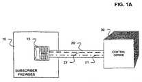
- FIG. 1Ashows an illustration of a known method of providing power to a communications device.
- a subscriber premises 10can include a land-line telephone 15 connected via land-line 20 to central office 30 .
- the land-line 20can provide both a communication path and power for land-line telephone 15 .
- the land-line 20can include a set of communications wires 22 that can carry communications signals (e.g., voice signals) to and from land-line telephone 15 .
- Land-line 20can also include a set of power wires 21 that can provide power to the land-line telephone 15 .
- One intent of providing the power for the land-line telephone 15 from the central office 30was to support operations of the land-line telephone 15 such as dialing capabilities, power for the internal circuitry of the phone, power to ring the telephone, etc.
- the power that has been supplied by the central office, as indicated in the above cited patents,has also come to be used to provide power to other communication elements which interface with the land-line 20 to provide communications over the land-line. For instance, in U.S. Pat. No.
- the systemprovides power to a base station unit that carries communications to the land-line phone from a computer.
- the other patentsshow examples of other communication equipment powered by the land-line over which the communication occurs.
- the communication deviceengages in communications over the same land-line that provides power to the communications device.
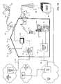
- FIG. 1Bshows a known subscriber premises including communications appliances. As illustrated in FIG. 1B , it has become common for a single location, such as a subscriber premises (e.g., a residence, a business premises, etc), to include many other communication appliances in addition to wireless communications devices. These additional communications appliances typically connect to disparate networks which support varied communications and can be powered by different methods and means.
- a subscriber premises 10can include one or more communication appliances such as a television 110 , a personal computer 120 , a telephone 130 , a telephone handset 75 , etc. Each of these communication devices can interface to an external network.
- television 110can be in communication with a satellite broadcast system (e.g., a Direct Broadcast System (DBS)) via a satellite dish 193 and satellite 190 .
- Television 110can also be in communication with a wireless cable system and/or a broadcast television antenna 113 that receives over-the-air television signals.
- Television 110can also be in communication with a cable head end 155 of a cable network 150 via cable 151 coupled to cable television interface unit 152 located at the subscriber premises 10 .
- the term coupledencompasses a direct connection and an indirect connection
- the term communicationencompasses a direct communication and an indirect communication.
- Cable television interface unit 152is typically powered by a connection of a power converter to a standard 60 Hz, 110 volt electrical outlet.
- the cable television interface unit 152can be, for example, a set top box associated with the cable network 150 .
- PC 120can be coupled to a telecommunications network such as the public switched telephone network (PSTN) 160 via a local exchange carrier (LEC) 165 and a telephone interface unit 122 .
- Telephone interface unit 122typically receives power from at least one of land-line 20 from LEC 165 , a connection of a power converter to a standard 60 Hz, 110 volt electrical outlet (e.g., a modem drawing power from a power supply of PC 120 coupled to an electrical outlet), etc.
- the PC 120can be connected to a data network such as an Internet protocol (IP) network 170 by an Internet service provider (ISP) 175 coupled to the LEC 165 .
- IPInternet protocol
- ISPInternet service provider
- Telephone unit 130can be coupled to the telephone interface unit 122 for a connection to the PSTN 160 and can receive power from land-line 20 to LEC 165 .
- Handset 75can be part of a fixed wireless system.
- a fixed wireless base station 72e.g., a receiver/transmitter including a wireless interface unit, etc.
- the fixed wireless base station 72can communicate via antennae 73 and wireless base station 183 with a wireless switch 180 (e.g., at a wireless switching center).
- the fixed wireless communicationscan be via over-the-air transmissions with wireless base station 183 assigned to the area in which the subscriber premises 10 are located.
- a fixed wireless systemcan be deemed to be a “fixed” wireless system in that a transceiver (e.g., fixed wireless base station 72 ) for over-the-air communications are not mobile, but rather stationary and associated with a given subscriber premises.
- a fixed wireless systemcan include a portable component such as handset 75 in communication with a fixed wireless base station 72 at a given subscriber premises 10 .
- a known fixed wireless bases stationtypically draws power from a connection of a power converter to a standard 60 Hz, 110 volt electrical outlet, and either engages in communications over the same land-line that provides power to the communications appliance or is susceptible to power utility power outages.
- Embodiments of the present inventioninclude apparatus and methods to provide power to a communications device.
- a wireless communications unitcan receive power from a local exchange carrier and engage in wireless communications with a wireless switch.
- FIG. 1Ashows an illustration of a known method of providing power to a communications device.
- FIG. 1Bshows a known subscriber premises including communications appliances.
- FIG. 2shows a system in accordance with an embodiment of the present invention.
- FIG. 3shows a system in accordance with an embodiment of the present invention.
- FIG. 4shows a system in accordance with an embodiment of the present invention.
- FIG. 5shows a system in accordance with an embodiment of the present invention.
- Embodiments of the present inventionrelate to providing power to a communications device (e.g., a wireless transceiver) so that communications can be supported despite a power disruption (e.g. a power outage) of an electrical utility.
- a communications devicee.g., a wireless transceiver
- communicationscan be supported notwithstanding a power disruption of an electrical utility by receiving power from a land-line connection to a central office of a local exchange carrier (LEC).
- LEClocal exchange carrier
- a wireless communications transceiverincludes a handset and the transceiver includes a power converter that receives power from the land-line connection and matches it to the power specifications for the wireless communication transceiver (e.g., a cellular transceiver).
- the wireless transceivercan be part of a fixed wireless base station in communication with a wireless switch, and a handset can engage in cordless communications with the wireless transceiver.
- Power conversion circuitscan be disposed in the fixed wireless base station with the wireless transceiver.
- a usercan have the benefit of a cordless telephone in communications with a fixed wireless transceiver, where the fixed wireless transceiver is powered by power from a local exchange carrier.
- a wireless transceivercan receive power from the local exchange carrier over a land-line connection, and the wireless transceiver does not use the land-line connection for any purpose other than to receive power. As a consequence, the wireless transceiver can remain powered even in the event of an electrical utility power outage that might otherwise disadvantageously effect wireless communications.
- FIG. 2shows a system in accordance with an embodiment of the present invention.
- a wireless transceiver 70 located at subscriber premises 10can include an antenna 71 for wireless communication with a wireless switch 180 via base station 183 .
- wireless communication between the wireless transceiver 70 and the wireless switch 180is similar to that in the cellular environment (e.g., an Advance Mobile Phone Service (AMPS) analog cellular phone system, an Interim Standard 41 (IS-41) compliant cellular system, an IS-54 dual mode (analog and digital) compliant wireless system, etc.).
- AMPSAdvance Mobile Phone Service
- IS-41Interim Standard 41
- IS-54 dual modeanalog and digital
- wireless communication between the wireless transceiver 70 and the wireless switch 180includes communications according to digital wireless communications protocols such as an IS-55 Time Division Multiple Access (TDMA) digital wireless communications protocol, an IS-95 Code Division Multiple Access (CDMA) digital wireless communications protocol, Groupe Speciale Mobile (GSM), third generation standard, Third Generation (3G), Wireless Application Protocol (WAP), Global Positioning System, an IS-136 TDMA digital wireless communications protocol including a Digital Control Channel (DCCH), etc.
- TDMATime Division Multiple Access
- CDMACode Division Multiple Access
- GSMGroupe Speciale Mobile
- 3GThird Generation
- WAPWireless Application Protocol
- DCCHDigital Control Channel
- wireless switch 180is part of a mobile switching center.
- the wireless transceiver 70can be coupled via a plug 60 to a wall outlet or receptacle unit 50 which is coupled to power wires 21 of a land-line that connects the subscriber premises 10 to the central office 30 (e.g., via the power wires 21 of land-line 20 of FIG. 1A , etc.).
- the plug 60in its connection to the receptacle unit 50 , receives power from the power wires 21 . That power can be provided to circuitry internal to the wireless transceiver 70 .
- the circuitryconverts the received power to the appropriate power specification prescribed for operating the wireless transceiver 70 .
- circuitsare known and can considered analogous to circuitry already existing in cellular phones that derive power, for example, from an automobile power source (e.g., a direct current (DC) power source) or from a typical electrical utility power source, (e.g., a standard 60 Hz, 110 volt alternating current (AC) power source), etc.
- DCdirect current
- ACvolt alternating current
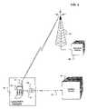
- FIG. 3shows a system in accordance with an embodiment of the present invention.
- Subscriber premises 10can include a fixed wireless base station 72 that receives power from central office 30 via power lines 21 of a land-line connecting subscriber premises 10 and central office 30 .
- Fixed wireless base station 72can include a wireless transceiver that is powered by power received from the central office 30 .
- a handset 75can engage in cordless communication with the fixed wireless base station 72 .
- Cordless communicationstypically involve a direct communication between a handset and a base over at least one of dedicated set of frequencies for cordless communications such as 46/49 MHz, 900 MHz, 2.4 GHz, etc.
- Cordless communications between a handset and baseobviate the need for the typical coiled cord that can connect a telephone handset to a telephone base.
- wireless communicationse.g., cellular communications between a cellular transceiver and cellular base station, wireless communications (e.g., AMPS, IS-41, IS-54, IS-55, IS-95, IS-136, etc.) between a wireless transceiver and a wireless base station connected to a wireless switch, etc.) do not include cordless communications.
- the fixed wireless base station 72powered by the power from the central office 30 , can engage in wireless communications via antenna 73 with wireless base station 183 and wireless switch 180 .
- power conversion circuitrycan be disposed within fixed wireless base station 72 to convert the power received from central office 30 into a form suitable for powering circuitry of the fixed wireless base station 72 .
- a wireless communications subscribercan have all of the benefits of wireless communication in a fixed location (e.g., at a subscriber premises, a residence, a place of business, etc.) while reducing a vulnerability to power utility power outages that can otherwise inhibit communications.
- Certain embodiments of the present advantagecan be simply installed in many subscriber premises because a typical subscriber premise has a plurality of phone receptacles (e.g., receptacle 50 of FIG. 2 ) coupled to a central office.
- a land-linecan be used to provide land-line communications service to a subscriber premises and also provide power for a wireless communication device (e.g., transceiver) when the wireless communication device is coupled to an outlet or receptacle that is not serving a land-line telephone set or other land-line communication device.
- a wireless communication devicee.g., transceiver
- Embodiments of the present inventioncan provide a dependable power connection to a wireless communication device that enhances the subscriber's wireless communication capabilities with an uncomplicated installation.
- a subscriber interface unite.g., a digital splitter, etc.
- a subscriber interface unitsuch as a digital splitter is coupled to various internal communication networks at a subscriber premises, and each internal communications network includes at least one communications appliance. Examples of such internal communications networks include a telephone network, a local area network (e.g. a personal computer (PC) local area network, etc.), a television transmission network, etc.
- the digital splitteralso can interface to a plurality of external networks, such as a local telephone service via a local exchange carrier, a cable system head end, a wireless communication system, an optical fiber network or other information delivery systems.
- a digital splittercan oversee control signals from at least one of the external networks to control the coupling operations performed by the splitter.
- a controller associated with the cable networke.g., at or associated with a cable head, at or associated with the cable network, etc.
- a controller on one of the external networkscan remotely enable or disable various ones of the services to which a subscriber subscribes.
- the digital splitterin response to such controls, can then either enable or disable the provisioning of the service to the appropriate communication appliance(s) at the subscriber premises.
- the digital splittercan be provided as a basic digital splitter together with an enhanced digital splitter whereby the enhanced digital splitter includes a backplane that supports plug-in modules defining different system functions.
- a subscriber at a premisesmay have a telephonic communication appliance such as a wireless transceiver coupled to a digital splitter.
- the wireless transceivercan communicate with a cordless handset, a wireline telephonic communications appliance, etc.
- the subscriber premisecan also have a wireline connection to the local exchange carrier so that the carrier can carry telephonic communications to and from the subscriber premises (e.g., to a wireline telephone communication appliance at the subscriber premises). It may also be desirable to use the wireline telephone communication appliance for purposes of conducting telephonic communications over a data network, e.g., conducting voice over Internet Protocol (VoIP) applications.
- VoIPvoice over Internet Protocol
- the digital splitter at the subscriber premisescan act as a controller to selectively couple the subscriber telephone communication appliance to one of the cable network, the wireless transceiver, the wireline connection to the local exchange carrier.
- the digital splittercan direct communications to and from the subscriber premises via the cable facilities while still maintaining a back-up connection, such as a back-up connection to a local exchange carrier via a standard wireline connection to that carrier, a back-up wireless connection, etc.
- the digital splittercan draw power from the local exchange carrier and continue to direct communications to and from the subscriber premises.
- This exampleis merely representative of one type of communication appliance which might be coupled to a plurality of external networks.
- the external networks describedare only examples.
- Other external networkscan interface with the digital splitter, which can draw power from the local exchange carrier in accordance with embodiments of the present invention.
- a digital splittercan provide an external network with the capability of controlling the services that are provisioned to the communication appliances.
- a controller associated with an external networke.g., a cable network
- an external networkcan control the coupling of the telephonic communication appliance between the various external networks and also can define the types of functionality to be provisioned to the telephonic communications appliance (e.g., by sending control signals over the cable network to the digital splitter).
- an external networkcan control the types of services which may be accessed by any of the communications appliances, (e.g., the television, the PC, or telephone) via any of the external networks.
- an integrated service providerthat is capable of providing a plurality of communications services (e.g., cable video programming, data communication links, telephonic communications capabilities, wireless communications, etc.) to a single subscriber can control the operation of the digital splitter so as to permit access to individual services of the integrated services.
- communications servicese.g., cable video programming, data communication links, telephonic communications capabilities, wireless communications, etc.
- FIG. 4shows a system in accordance with an embodiment of the present invention.
- a subscriber premisescan include a plurality of communication appliances such as one or more televisions 110 , one or more personal computers 120 , one or more telephones 130 , a fixed wireless base station 72 , a handset 75 that can cordlessly communicate with fixed wireless base station 72 , etc.
- Each of these types of appliancescan be coupled to a digital splitter 400 .
- the digital splitter 400also can be coupled to a plurality of external networks.
- the digital splitter 400can be coupled to a local exchange carrier (LEC) 165 of PSTN 160 , and the LEC 165 can provide power to the digital splitter 400 .
- LEClocal exchange carrier
- the digital splitter 400can also be coupled to a cable head end 465 which is capable of providing video programming as well as data and other communication services over high-bandwidth cable 461 .
- the digital splitter 400in one embodiment, also can be connected to other communication networks, such as an over-the-air television network via antenna 113 , a satellite broadcast system via a satellite dish 193 and satellite 190 , a wireless communications network via fixed wireless base station 72 and antenna 73 in communication with wireless base station 183 and wireless switch 180 .
- the digital splitter 400can also be coupled to IP network 450 via cable network 460 and gateway 455 . Gateway 455 can adapt communications received from cable network 460 into communications suitable for transmission via IP network 450 .
- the digital splitter 400can also be coupled to PSTN 160 via cable network 460 , gateway 455 , and gateway 456 .
- Gateway 456can adapt communications received via IP network 450 into communications suitable for transmission via PSTN 160 .
- Embodiments of the present inventionare not limited to particular internal networks or external networks, nor are they limited to this particular combination of internal or external networks.
- alternative wireless networkscould be supported in substitute for or in addition to the fixed wireless capability referred to in FIG. 4 .
- the digital splitteroperates to selectively couple appliances to a selected external network.
- the telephonic appliance 130can have the capability of communicating via either PSTN 165 or via telephonic capabilities provided over cable 461 and cable network 460 .
- the digital splitter 400in response to control signals from one of the external networks (e.g., from a cable network provider, from a controller at cable head end 465 , etc), selects which external network the telephone 130 can be connected or connectable to any given time.
- the digital splitter 400can be instructed to establish a default connection of the telephone to the cable network 460 via cable 461 rather than to the PSTN via a wireline connection. Then, should the cable head end 465 detect the occurrence of a condition that would warrant changing the default connection, the cable head end 465 could transmit a control signal to the digital splitter 400 to change the default connection and enable communications between the PSTN 160 and the telephone appliance 130 via the wireline connection. Similarly, the digital splitter 400 can control a connection of a PC 120 to data communications transmission equipment such as along the cable network 460 , the IP network 450 , or the PSTN 160 .
- the cable head end 465can include control capabilities to select which services the subscriber at the premises 10 is entitled to receive.
- an operator of cable head end 465can provide a plurality of services to a subscriber. These services can all be supplied via the cable 461 , or alternatively could be provided via a plurality of the external networks, such as providing video programming and VoIP telephony via the cable 461 , wireless communications via a wireless network, and IP network communications.
- the digital splitter 400typically receives power from a power utility, e.g., via a standard, 60 Hz, 110 volt alternating current (AC) power outlet coupled to the power utility.
- a power utility power outagein one embodiment, communications (e.g., voice communications, data communications, etc.) via cable 461 can be interrupted.
- digital splitter 400can receive power from LEC 165 via power wires 21 of landline 20 .
- the digital splitter 400upon detecting a power utility power outage, can establish a connection for communications via a communications appliance that can engage in communications while powered by power from LEC 165 via power wires 21 of the landline 20 .
- digital splitter 400can have established, maintained or controlled a connection for communications (e.g. telephonic communications, data communications) via cable 461 and draw power from a power utility.
- communicationse.g. telephonic communications, data communications
- the digital splitter 400can draw power from LEC 165 via power wires 21 of landline 20 and establish an alternative communications connection, e.g., a communications connection to LEC 165 via communications wires 22 of landline 20 , a communications connection to a wireless network via fixed wireless base station 72 and antennae 73 , etc.
- FIG. 5shows a system in accordance with an embodiment of the present invention.
- a subscriber premise 10includes an interface unit 500 that can interface communications between a PC 120 and cable head end 465 , between a telephone 130 and cable head end 465 , etc.
- interface unit 500includes a cable modem 510 coupled to PC 120 and a broadband telephone interface unit 520 coupled to telephone 130 .
- PC 120can communication with IP network 450 and/or PSTN 160 via cable modem 510 and cable network 460 .
- Telephone 130can communicate with PSTN 160 via IP network 450 , cable network 460 , cable modem 510 , and broadband telephone interface unit 520 .
- communications between telephone 130 and PSTN 160are typically communicated over cable 461 , and interface unit 500 draws power from a power utility.
- such communicationscan be maintained over cable 461 while the interface unit 500 draws power from LEC 165 via power wires 21 .
- such communicationscan not be maintained over cable 461 when the interface unit 500 draws power from LEC 165 via power wires 21 , and the interface unit 500 can establish an alternative communications connection, e.g., a communications connection to LEC 165 via communications wires 22 of landline 20 , a wireless communication connection to a wireless network via a wireless transceiver coupled to interface unit 500 , etc.
Landscapes
- Engineering & Computer Science (AREA)
- Signal Processing (AREA)
- Mobile Radio Communication Systems (AREA)
- Telephonic Communication Services (AREA)
Abstract
Description
Claims (18)
Priority Applications (1)
| Application Number | Priority Date | Filing Date | Title |
|---|---|---|---|
| US10/866,994US7099707B2 (en) | 1997-10-10 | 2004-06-15 | Method and system for providing power to a communications device |
Applications Claiming Priority (3)
| Application Number | Priority Date | Filing Date | Title |
|---|---|---|---|
| US08/948,777US6256518B1 (en) | 1997-10-10 | 1997-10-10 | System for providing power to a wireless system |
| US09/828,859US7149553B2 (en) | 1997-10-10 | 2001-04-10 | Method and system for providing power to a communications device |
| US10/866,994US7099707B2 (en) | 1997-10-10 | 2004-06-15 | Method and system for providing power to a communications device |
Related Parent Applications (1)
| Application Number | Title | Priority Date | Filing Date |
|---|---|---|---|
| US09/828,859DivisionUS7149553B2 (en) | 1997-10-10 | 2001-04-10 | Method and system for providing power to a communications device |
Publications (2)
| Publication Number | Publication Date |
|---|---|
| US20040235414A1 US20040235414A1 (en) | 2004-11-25 |
| US7099707B2true US7099707B2 (en) | 2006-08-29 |
Family
ID=25488244
Family Applications (3)
| Application Number | Title | Priority Date | Filing Date |
|---|---|---|---|
| US08/948,777Expired - LifetimeUS6256518B1 (en) | 1997-10-10 | 1997-10-10 | System for providing power to a wireless system |
| US09/828,859Expired - Fee RelatedUS7149553B2 (en) | 1997-10-10 | 2001-04-10 | Method and system for providing power to a communications device |
| US10/866,994Expired - Fee RelatedUS7099707B2 (en) | 1997-10-10 | 2004-06-15 | Method and system for providing power to a communications device |
Family Applications Before (2)
| Application Number | Title | Priority Date | Filing Date |
|---|---|---|---|
| US08/948,777Expired - LifetimeUS6256518B1 (en) | 1997-10-10 | 1997-10-10 | System for providing power to a wireless system |
| US09/828,859Expired - Fee RelatedUS7149553B2 (en) | 1997-10-10 | 2001-04-10 | Method and system for providing power to a communications device |
Country Status (4)
| Country | Link |
|---|---|
| US (3) | US6256518B1 (en) |
| BR (1) | BR9803890A (en) |
| CA (1) | CA2249911C (en) |
| TW (1) | TW404105B (en) |
Cited By (9)
| Publication number | Priority date | Publication date | Assignee | Title |
|---|---|---|---|---|
| US20050041797A1 (en)* | 1998-01-14 | 2005-02-24 | Bellovin Steven Michael | Method and system for telephony and high-speed data access on a broadband access network |
| US7317793B2 (en) | 2003-01-30 | 2008-01-08 | Serconet Ltd | Method and system for providing DC power on local telephone lines |
| US7424031B2 (en) | 1998-07-28 | 2008-09-09 | Serconet, Ltd. | Local area network of serial intelligent cells |
| US7483524B2 (en) | 1999-07-20 | 2009-01-27 | Serconet, Ltd | Network for telephony and data communication |
| US7522714B2 (en) | 2000-03-20 | 2009-04-21 | Serconet Ltd. | Telephone outlet for implementing a local area network over telephone lines and a local area network using such outlets |
| US8582598B2 (en) | 1999-07-07 | 2013-11-12 | Mosaid Technologies Incorporated | Local area network for distributing data communication, sensing and control signals |
| US9674678B2 (en)* | 1999-04-21 | 2017-06-06 | Commscope Technologies Llc | Architecture for signal and power distribution in wireless data network |
| US10986164B2 (en) | 2004-01-13 | 2021-04-20 | May Patents Ltd. | Information device |
| US11044109B2 (en) | 2015-09-30 | 2021-06-22 | Hewlett-Packard Development Company, L.P. | Utilizing a data cable infrastructure to provide power |
Families Citing this family (24)
| Publication number | Priority date | Publication date | Assignee | Title |
|---|---|---|---|---|
| US6856799B1 (en)* | 1998-12-24 | 2005-02-15 | Swisscom Mobile Ag | Communications system, communication method and corresponding devices |
| US6571181B1 (en)* | 1999-08-11 | 2003-05-27 | Broadcom Corporation | System and method for detecting a device requiring power |
| US6763233B2 (en)* | 2000-01-05 | 2004-07-13 | Nortel Networks Limited | Terminal roaming operations between intergenerational wireless networks |
| NO316627B1 (en)* | 2000-01-12 | 2004-03-15 | Ericsson Telefon Ab L M | Private cordless WAP system |
| US8285292B1 (en)* | 2000-02-11 | 2012-10-09 | At&T Mobility Ii Llc | Detection of cross-connection between a wireless loop network and another loop network at a subscriber's premises |
| US20040166833A1 (en)* | 2001-03-02 | 2004-08-26 | Dan Shklarsky | Mobile radio service over catv network |
| US7096049B2 (en)* | 2001-05-25 | 2006-08-22 | Palm, Inc. | Wireless transaction enabled handheld computer system and method |
| US20060128376A1 (en)* | 2002-07-09 | 2006-06-15 | Alexis Glenroy J | Communication systems and methods |
| US7565115B2 (en)* | 2002-07-09 | 2009-07-21 | Xcelis Communications, Llc | Communication system for landline and wireless calls |
| US7299060B1 (en)* | 2002-12-10 | 2007-11-20 | Sprint Spectrum L.P. | Method and system for wireless bridging |
| FR2853114A1 (en)* | 2003-03-26 | 2004-10-01 | France Telecom | DEVICE FOR TRANSMITTING INFORMATION ACQUIRED BY A REMOTE TELECOMMUNICATION APPARATUS AND SYSTEM IMPLEMENTING SUCH A DEVICE. |
| US20050048968A1 (en)* | 2003-08-28 | 2005-03-03 | Martin Haueis | Wireless communication system with a supplemental communication sub-system |
| US20050180366A1 (en)* | 2004-02-13 | 2005-08-18 | Excell Matthew W. | Voice over internet communications convergence system |
| WO2005101804A1 (en)* | 2004-04-13 | 2005-10-27 | Telecom Italia S.P.A. | A device and a method for feeding electric devices from a telephone line |
| US7376221B1 (en)* | 2004-08-20 | 2008-05-20 | Verizon Services Corp. | Methods and apparatus for multi-mode telephone |
| US7738858B2 (en)* | 2004-10-18 | 2010-06-15 | Natan Epstein | Wireless messaging system |
| US7606529B1 (en)* | 2005-12-14 | 2009-10-20 | Sprint Communications Company L.P. | Wireless-signal distribution system via set-top box |
| WO2007120145A1 (en)* | 2006-04-18 | 2007-10-25 | Natan Epstein | Wireless messaging system |
| US8776185B2 (en)* | 2008-12-22 | 2014-07-08 | At&T Intellectual Property I, L.P. | Integrated service identity for different types of information exchange services |
| CN101621863B (en)* | 2009-08-11 | 2012-09-05 | 北京华智大为科技有限公司 | Portable mobile terminal |
| US8983059B2 (en) | 2011-11-03 | 2015-03-17 | Bruce H. Turner | Telephone interface |
| US8306197B1 (en)* | 2011-11-03 | 2012-11-06 | Turner Bruce H | Telephone interface |
| CA2892512A1 (en)* | 2012-11-28 | 2014-06-05 | Renewable Edge, Llc | Custom wireless retrofitted solar powered public telephone |
| US20170142030A1 (en)* | 2015-11-12 | 2017-05-18 | ComplexIQ Inc. | Digital coax network splitter |
Citations (30)
| Publication number | Priority date | Publication date | Assignee | Title |
|---|---|---|---|---|
| US4232200A (en) | 1978-10-23 | 1980-11-04 | United Networks, Inc. | Dialing system |
| JPS5720156A (en) | 1980-07-11 | 1982-02-02 | Toubishi Kosan Kk | Ultrathin motor |
| US4847899A (en) | 1986-11-20 | 1989-07-11 | Sharp Kabushiki Kaisha | Power circuit for telephone accessory devices |
| JPH0220156B2 (en) | 1984-06-21 | 1990-05-08 | Ibiden Co Ltd | |
| US5111499A (en) | 1986-09-26 | 1992-05-05 | Kabushiki Kaisha Toshiba | Cordless telephone apparatus having a ringer circuit operable during power failure |
| US5157711A (en) | 1989-08-31 | 1992-10-20 | Kabushiki Kaisha Toshiba | Telephone terminal device |
| US5173899A (en) | 1987-11-27 | 1992-12-22 | British Telecommunications Public Limited Company | Tdma communications network of transmitting information between a central station and remote stations |
| US5343514A (en) | 1993-12-10 | 1994-08-30 | Snyder Gary K | Telephone line powered system |
| US5353331A (en) | 1992-03-05 | 1994-10-04 | Bell Atlantic Network Services, Inc. | Personal communications service using wireline/wireless integration |
| US5400388A (en) | 1991-04-23 | 1995-03-21 | Samsung Electronics Co., Ltd. | Circuit and method for operating a radio telephone upon loss of AC power |
| US5508733A (en) | 1988-10-17 | 1996-04-16 | Kassatly; L. Samuel A. | Method and apparatus for selectively receiving and storing a plurality of video signals |
| US5553138A (en) | 1994-05-13 | 1996-09-03 | Compaq Computer Corporation | Telephone line sourced power supply |
| US5587734A (en) | 1990-09-28 | 1996-12-24 | Ictv, Inc. | User interface for selecting television information services through pseudo-channel access |
| US5594789A (en) | 1994-10-13 | 1997-01-14 | Bell Atlantic Network Services, Inc. | Transaction implementation in video dial tone network |
| US5661796A (en) | 1994-09-29 | 1997-08-26 | Sony Corporation | Telephone set |
| US5673308A (en) | 1994-10-12 | 1997-09-30 | Bell Atlantic Network Services, Inc. | Personal phone number system |
| US5687228A (en) | 1995-08-30 | 1997-11-11 | Plantronics, Inc. | Universal amplified telephone handset |
| US5729197A (en)* | 1996-02-22 | 1998-03-17 | Ultra Communications Corporation | Automatic, self-triggering alarm processing system and method |
| US5734711A (en) | 1994-05-20 | 1998-03-31 | Siemens Aktiengesellschaft | Telecommunication system with energy-saving mode |
| US5774527A (en) | 1993-08-19 | 1998-06-30 | News Datacom Ltd. | Integrated telephone and cable communication networks |
| US5790177A (en) | 1988-10-17 | 1998-08-04 | Kassatly; Samuel Anthony | Digital signal recording/reproduction apparatus and method |
| US5815088A (en) | 1993-12-28 | 1998-09-29 | Kurtz; Fred R. | RF switching with remote controllers dedicated to other devices |
| US5857010A (en) | 1994-06-07 | 1999-01-05 | Canon Kabushiki Kaisha | Power-failure resistant communication system |
| US5889856A (en)* | 1997-05-22 | 1999-03-30 | Centillium Technology Corp. | ADSL integrated line card with digital splitter and POTS CODEC without bulky analog splitter |
| US5946617A (en) | 1996-06-28 | 1999-08-31 | Telxon Corporation | Cellular communication system with remote power source for providing power to access points |
| US5970138A (en) | 1995-12-04 | 1999-10-19 | Fujitsu Limited | Terminal equipment for telecommunications and information processing |
| US6073031A (en) | 1997-12-24 | 2000-06-06 | Nortel Networks Corporation | Desktop docking station for use with a wireless telephone handset |
| US6088599A (en) | 1997-05-23 | 2000-07-11 | Matsushita Electric Industrial Co., Ltd. | Fixed subscriber unit |
| US20020130641A1 (en)* | 2001-03-09 | 2002-09-19 | Schofield Wade S. | Apparatus and method for providing span power to communication equipment at a customer premise |
| US6584197B1 (en)* | 1998-12-03 | 2003-06-24 | Adtran Inc. | Power-limited remote termination converter with wetting current and emergency power operation for digital data transmission equipment |
Family Cites Families (4)
| Publication number | Priority date | Publication date | Assignee | Title |
|---|---|---|---|---|
| US4983604A (en)* | 1987-11-13 | 1991-01-08 | The Rockefeller University | Inhibitors of nonenzymatic cross-linking |
| US4995072A (en)* | 1989-06-30 | 1991-02-19 | Harold Sandler | Self-powered base and remote telephone communication set |
| TW226510B (en)* | 1993-01-19 | 1994-07-11 | Novatel Comm Ltd | Wireline interface for cellular telephone |
| US6075496A (en)* | 1997-01-16 | 2000-06-13 | Flash Comm, Inc. | Shunt feed antenna for large terrestrial vehicles |
- 1997
- 1997-10-10USUS08/948,777patent/US6256518B1/ennot_activeExpired - Lifetime
- 1998
- 1998-10-09CACA002249911Apatent/CA2249911C/ennot_activeExpired - Lifetime
- 1998-10-09BRBR9803890-7Apatent/BR9803890A/ennot_activeIP Right Cessation
- 1998-10-12TWTW087116827Apatent/TW404105B/ennot_activeIP Right Cessation
- 2001
- 2001-04-10USUS09/828,859patent/US7149553B2/ennot_activeExpired - Fee Related
- 2004
- 2004-06-15USUS10/866,994patent/US7099707B2/ennot_activeExpired - Fee Related
Patent Citations (30)
| Publication number | Priority date | Publication date | Assignee | Title |
|---|---|---|---|---|
| US4232200A (en) | 1978-10-23 | 1980-11-04 | United Networks, Inc. | Dialing system |
| JPS5720156A (en) | 1980-07-11 | 1982-02-02 | Toubishi Kosan Kk | Ultrathin motor |
| JPH0220156B2 (en) | 1984-06-21 | 1990-05-08 | Ibiden Co Ltd | |
| US5111499A (en) | 1986-09-26 | 1992-05-05 | Kabushiki Kaisha Toshiba | Cordless telephone apparatus having a ringer circuit operable during power failure |
| US4847899A (en) | 1986-11-20 | 1989-07-11 | Sharp Kabushiki Kaisha | Power circuit for telephone accessory devices |
| US5173899A (en) | 1987-11-27 | 1992-12-22 | British Telecommunications Public Limited Company | Tdma communications network of transmitting information between a central station and remote stations |
| US5508733A (en) | 1988-10-17 | 1996-04-16 | Kassatly; L. Samuel A. | Method and apparatus for selectively receiving and storing a plurality of video signals |
| US5790177A (en) | 1988-10-17 | 1998-08-04 | Kassatly; Samuel Anthony | Digital signal recording/reproduction apparatus and method |
| US5157711A (en) | 1989-08-31 | 1992-10-20 | Kabushiki Kaisha Toshiba | Telephone terminal device |
| US5587734A (en) | 1990-09-28 | 1996-12-24 | Ictv, Inc. | User interface for selecting television information services through pseudo-channel access |
| US5400388A (en) | 1991-04-23 | 1995-03-21 | Samsung Electronics Co., Ltd. | Circuit and method for operating a radio telephone upon loss of AC power |
| US5353331A (en) | 1992-03-05 | 1994-10-04 | Bell Atlantic Network Services, Inc. | Personal communications service using wireline/wireless integration |
| US5774527A (en) | 1993-08-19 | 1998-06-30 | News Datacom Ltd. | Integrated telephone and cable communication networks |
| US5343514A (en) | 1993-12-10 | 1994-08-30 | Snyder Gary K | Telephone line powered system |
| US5815088A (en) | 1993-12-28 | 1998-09-29 | Kurtz; Fred R. | RF switching with remote controllers dedicated to other devices |
| US5553138A (en) | 1994-05-13 | 1996-09-03 | Compaq Computer Corporation | Telephone line sourced power supply |
| US5734711A (en) | 1994-05-20 | 1998-03-31 | Siemens Aktiengesellschaft | Telecommunication system with energy-saving mode |
| US5857010A (en) | 1994-06-07 | 1999-01-05 | Canon Kabushiki Kaisha | Power-failure resistant communication system |
| US5661796A (en) | 1994-09-29 | 1997-08-26 | Sony Corporation | Telephone set |
| US5673308A (en) | 1994-10-12 | 1997-09-30 | Bell Atlantic Network Services, Inc. | Personal phone number system |
| US5594789A (en) | 1994-10-13 | 1997-01-14 | Bell Atlantic Network Services, Inc. | Transaction implementation in video dial tone network |
| US5687228A (en) | 1995-08-30 | 1997-11-11 | Plantronics, Inc. | Universal amplified telephone handset |
| US5970138A (en) | 1995-12-04 | 1999-10-19 | Fujitsu Limited | Terminal equipment for telecommunications and information processing |
| US5729197A (en)* | 1996-02-22 | 1998-03-17 | Ultra Communications Corporation | Automatic, self-triggering alarm processing system and method |
| US5946617A (en) | 1996-06-28 | 1999-08-31 | Telxon Corporation | Cellular communication system with remote power source for providing power to access points |
| US5889856A (en)* | 1997-05-22 | 1999-03-30 | Centillium Technology Corp. | ADSL integrated line card with digital splitter and POTS CODEC without bulky analog splitter |
| US6088599A (en) | 1997-05-23 | 2000-07-11 | Matsushita Electric Industrial Co., Ltd. | Fixed subscriber unit |
| US6073031A (en) | 1997-12-24 | 2000-06-06 | Nortel Networks Corporation | Desktop docking station for use with a wireless telephone handset |
| US6584197B1 (en)* | 1998-12-03 | 2003-06-24 | Adtran Inc. | Power-limited remote termination converter with wetting current and emergency power operation for digital data transmission equipment |
| US20020130641A1 (en)* | 2001-03-09 | 2002-09-19 | Schofield Wade S. | Apparatus and method for providing span power to communication equipment at a customer premise |
Cited By (36)
| Publication number | Priority date | Publication date | Assignee | Title |
|---|---|---|---|---|
| US8107479B2 (en)* | 1998-01-14 | 2012-01-31 | At&T Intellectual Property Ii, L.P. | Method and system for telephony and high-speed data access on a broadband access network |
| US20050041797A1 (en)* | 1998-01-14 | 2005-02-24 | Bellovin Steven Michael | Method and system for telephony and high-speed data access on a broadband access network |
| US8885660B2 (en) | 1998-07-28 | 2014-11-11 | Conversant Intellectual Property Management Incorporated | Local area network of serial intelligent cells |
| US8325636B2 (en) | 1998-07-28 | 2012-12-04 | Mosaid Technologies Incorporated | Local area network of serial intelligent cells |
| US8908673B2 (en) | 1998-07-28 | 2014-12-09 | Conversant Intellectual Property Management Incorporated | Local area network of serial intelligent cells |
| US8885659B2 (en) | 1998-07-28 | 2014-11-11 | Conversant Intellectual Property Management Incorporated | Local area network of serial intelligent cells |
| US8867523B2 (en) | 1998-07-28 | 2014-10-21 | Conversant Intellectual Property Management Incorporated | Local area network of serial intelligent cells |
| US7653015B2 (en) | 1998-07-28 | 2010-01-26 | Mosaid Technologies Incorporated | Local area network of serial intelligent cells |
| US7965735B2 (en) | 1998-07-28 | 2011-06-21 | Mosaid Technologies Incorporated | Local area network of serial intelligent cells |
| US8270430B2 (en) | 1998-07-28 | 2012-09-18 | Mosaid Technologies Incorporated | Local area network of serial intelligent cells |
| US7830858B2 (en) | 1998-07-28 | 2010-11-09 | Mosaid Technologies Incorporated | Local area network of serial intelligent cells |
| US7852874B2 (en) | 1998-07-28 | 2010-12-14 | Mosaid Technologies Incorporated | Local area network of serial intelligent cells |
| US7424031B2 (en) | 1998-07-28 | 2008-09-09 | Serconet, Ltd. | Local area network of serial intelligent cells |
| US7969917B2 (en) | 1998-07-28 | 2011-06-28 | Mosaid Technologies Incorporated | Local area network of serial intelligent cells |
| US7978726B2 (en) | 1998-07-28 | 2011-07-12 | Mosaid Technologies Incorporated | Local area network of serial intelligent cells |
| US7986708B2 (en) | 1998-07-28 | 2011-07-26 | Mosaid Technologies Incorporated | Local area network of serial intelligent cells |
| US10142813B2 (en) | 1999-04-21 | 2018-11-27 | Commscope Technologies Llc | Architecture for signal and power distribution in wireless data network |
| US9674678B2 (en)* | 1999-04-21 | 2017-06-06 | Commscope Technologies Llc | Architecture for signal and power distribution in wireless data network |
| US8582598B2 (en) | 1999-07-07 | 2013-11-12 | Mosaid Technologies Incorporated | Local area network for distributing data communication, sensing and control signals |
| US7522713B2 (en) | 1999-07-20 | 2009-04-21 | Serconet, Ltd. | Network for telephony and data communication |
| US8351582B2 (en) | 1999-07-20 | 2013-01-08 | Mosaid Technologies Incorporated | Network for telephony and data communication |
| US7483524B2 (en) | 1999-07-20 | 2009-01-27 | Serconet, Ltd | Network for telephony and data communication |
| US8929523B2 (en) | 1999-07-20 | 2015-01-06 | Conversant Intellectual Property Management Inc. | Network for telephony and data communication |
| US7492875B2 (en) | 1999-07-20 | 2009-02-17 | Serconet, Ltd. | Network for telephony and data communication |
| US8855277B2 (en) | 2000-03-20 | 2014-10-07 | Conversant Intellectual Property Managment Incorporated | Telephone outlet for implementing a local area network over telephone lines and a local area network using such outlets |
| US7522714B2 (en) | 2000-03-20 | 2009-04-21 | Serconet Ltd. | Telephone outlet for implementing a local area network over telephone lines and a local area network using such outlets |
| US7715534B2 (en) | 2000-03-20 | 2010-05-11 | Mosaid Technologies Incorporated | Telephone outlet for implementing a local area network over telephone lines and a local area network using such outlets |
| US8363797B2 (en) | 2000-03-20 | 2013-01-29 | Mosaid Technologies Incorporated | Telephone outlet for implementing a local area network over telephone lines and a local area network using such outlets |
| US7702095B2 (en) | 2003-01-30 | 2010-04-20 | Mosaid Technologies Incorporated | Method and system for providing DC power on local telephone lines |
| US7317793B2 (en) | 2003-01-30 | 2008-01-08 | Serconet Ltd | Method and system for providing DC power on local telephone lines |
| US8787562B2 (en) | 2003-01-30 | 2014-07-22 | Conversant Intellectual Property Management Inc. | Method and system for providing DC power on local telephone lines |
| US8107618B2 (en) | 2003-01-30 | 2012-01-31 | Mosaid Technologies Incorporated | Method and system for providing DC power on local telephone lines |
| US10986164B2 (en) | 2004-01-13 | 2021-04-20 | May Patents Ltd. | Information device |
| US11032353B2 (en) | 2004-01-13 | 2021-06-08 | May Patents Ltd. | Information device |
| US11095708B2 (en) | 2004-01-13 | 2021-08-17 | May Patents Ltd. | Information device |
| US11044109B2 (en) | 2015-09-30 | 2021-06-22 | Hewlett-Packard Development Company, L.P. | Utilizing a data cable infrastructure to provide power |
Also Published As
| Publication number | Publication date |
|---|---|
| CA2249911C (en) | 2002-01-01 |
| US20040235414A1 (en) | 2004-11-25 |
| US20020094848A1 (en) | 2002-07-18 |
| CA2249911A1 (en) | 1999-04-10 |
| TW404105B (en) | 2000-09-01 |
| BR9803890A (en) | 2000-01-04 |
| US6256518B1 (en) | 2001-07-03 |
| US7149553B2 (en) | 2006-12-12 |
Similar Documents
| Publication | Publication Date | Title |
|---|---|---|
| US7099707B2 (en) | Method and system for providing power to a communications device | |
| EP1031211B1 (en) | System and method for distributing voice and data information over wireless and wireline networks | |
| CA2200506C (en) | Dual-mode network access point | |
| US6546098B1 (en) | System and method for distributing enhanced telephony service to customer premises equipment | |
| US20070223465A1 (en) | System, method and article for VOIP and PSTN communication | |
| US20130003696A1 (en) | Device handing over communication session from wireless communication to powerline communication | |
| US20030219002A1 (en) | Communication system, communication control apparatus and communication terminal apparatus | |
| US7072675B1 (en) | Wireless docking station system and method for a multiple handset cordless telephone system | |
| WO2003041369A1 (en) | Telecommunications gateway and method | |
| US6658108B1 (en) | System and method for distributing power over a premises network | |
| US7519392B2 (en) | Integrated wireless local loop system | |
| EP1472868A1 (en) | Wired cellular telephone system | |
| US20020126696A1 (en) | Communication system and circuit controller | |
| CN101179298B (en) | Modem device of supporting power line and digital subscriber line access and implementing method thereof | |
| EP3562102B1 (en) | Devices, systems and methods for performing maintenance in docsis customer premise equipment (cpe) devices | |
| US9125227B2 (en) | Communications device for a wireless and land-line network | |
| US20050176417A1 (en) | Telecommunication system | |
| US5917895A (en) | Adjunct arrangement for a telecommunication device | |
| KR200325543Y1 (en) | Subscriber connection device of wide CDM wireless subscriber network embedded in computer | |
| MXPA98008387A (en) | System to provide energy to a system inalambr | |
| KR20040043352A (en) | charging system of the mobile communication terminal built in the power line communication modem | |
| WO2001004766A1 (en) | Method for coupling an internal appliance to one of a plurality of external networks | |
| US20020126628A1 (en) | Peripheral having a wireless transmission apparatus | |
| US8285292B1 (en) | Detection of cross-connection between a wireless loop network and another loop network at a subscriber's premises | |
| KR20030055561A (en) | WLL terminal having a variable communication circuit function |
Legal Events
| Date | Code | Title | Description |
|---|---|---|---|
| AS | Assignment | Owner name:CINGULAR WIRLEESS II, LLC, GEORGIA Free format text:CERTIFICATE OF CONVERSION;ASSIGNOR:CINGULAR WIRELESS II, INC.;REEL/FRAME:017546/0612 Effective date:20041027 Owner name:CINGULAR WIRLEESS II, LLC,GEORGIA Free format text:ASSIGNMENT OF ASSIGNORS INTEREST;ASSIGNOR:CINGULAR WIRELESS II, INC.;REEL/FRAME:017546/0612 Effective date:20041027 Owner name:CINGULAR WIRELESS II, INC.,GEORGIA Free format text:ASSIGNMENT OF ASSIGNORS INTEREST;ASSIGNOR:NEW CINGULAR WIRELESS SERVICES, INC. F/K/A AT&T WIRELESS SERVICES, INC.;REEL/FRAME:017555/0711 Effective date:20041027 Owner name:CINGULAR WIRELESS II, INC., GEORGIA Free format text:ASSIGNMENT OF ASSIGNORS INTEREST;ASSIGNOR:NEW CINGULAR WIRELESS SERVICES, INC. F/K/A AT&T WIRELESS SERVICES, INC.;REEL/FRAME:017555/0711 Effective date:20041027 Owner name:CINGULAR WIRLEESS II, LLC, GEORGIA Free format text:ASSIGNMENT OF ASSIGNORS INTEREST;ASSIGNOR:CINGULAR WIRELESS II, INC.;REEL/FRAME:017546/0612 Effective date:20041027 | |
| AS | Assignment | Owner name:CINGULAR WIRELESS II, LLC,GEORGIA Free format text:CERTIFICATE OF CONVERSION;ASSIGNOR:CINGULAR WIRELESS II, INC.;REEL/FRAME:017696/0375 Effective date:20041027 Owner name:CINGULAR WIRELESS II, LLC, GEORGIA Free format text:CERTIFICATE OF CONVERSION;ASSIGNOR:CINGULAR WIRELESS II, INC.;REEL/FRAME:017696/0375 Effective date:20041027 | |
| AS | Assignment | Owner name:CINGULAR WIRELESS II, LLC, GEORGIA Free format text:CONVERSION FROM "INC" TO "LLC";ASSIGNOR:CINGULAR WIRELESS II, INC.;REEL/FRAME:018090/0795 Effective date:20041027 Owner name:CINGULAR WIRELESS II, INC., GEORGIA Free format text:ASSIGNMENT OF ASSIGNORS INTEREST;ASSIGNOR:NEW CINGULAR WIRELESS SERVICES, INC.;REEL/FRAME:018090/0758 Effective date:20041027 Owner name:NEW CINGULAR WIRELESS SERVICES, INC., GEORGIA Free format text:CHANGE OF NAME;ASSIGNOR:AT&T WIRELESS SERVICES, INC.;REEL/FRAME:018100/0176 Effective date:20041026 | |
| AS | Assignment | Owner name:AT&T MOBILITY II, LLC, GEORGIA Free format text:CHANGE OF NAME;ASSIGNOR:CINGULAR WIRELESS II, LLC;REEL/FRAME:020874/0654 Effective date:20070420 | |
| AS | Assignment | Owner name:AT&T MOBILITY II LLC, GEORGIA Free format text:CHANGE OF NAME;ASSIGNOR:AT&T MOBILITY II, LLC;REEL/FRAME:020960/0352 Effective date:20070830 | |
| CC | Certificate of correction | ||
| FPAY | Fee payment | Year of fee payment:4 | |
| FPAY | Fee payment | Year of fee payment:8 | |
| FEPP | Fee payment procedure | Free format text:MAINTENANCE FEE REMINDER MAILED (ORIGINAL EVENT CODE: REM.) | |
| LAPS | Lapse for failure to pay maintenance fees | Free format text:PATENT EXPIRED FOR FAILURE TO PAY MAINTENANCE FEES (ORIGINAL EVENT CODE: EXP.); ENTITY STATUS OF PATENT OWNER: LARGE ENTITY | |
| STCH | Information on status: patent discontinuation | Free format text:PATENT EXPIRED DUE TO NONPAYMENT OF MAINTENANCE FEES UNDER 37 CFR 1.362 | |
| FP | Lapsed due to failure to pay maintenance fee | Effective date:20180829 |