US7099696B2 - Angle diversity dual antenna system - Google Patents
Angle diversity dual antenna systemDownload PDFInfo
- Publication number
- US7099696B2 US7099696B2US10/366,397US36639703AUS7099696B2US 7099696 B2US7099696 B2US 7099696B2US 36639703 AUS36639703 AUS 36639703AUS 7099696 B2US7099696 B2US 7099696B2
- Authority
- US
- United States
- Prior art keywords
- antenna
- antenna system
- channel
- combiner
- signal
- Prior art date
- Legal status (The legal status is an assumption and is not a legal conclusion. Google has not performed a legal analysis and makes no representation as to the accuracy of the status listed.)
- Expired - Lifetime, expires
Links
- 230000009977dual effectEffects0.000titledescription7
- 238000012544monitoring processMethods0.000abstractdescription2
- 238000004891communicationMethods0.000description4
- 238000005562fadingMethods0.000description4
- 230000005540biological transmissionEffects0.000description3
- 230000010287polarizationEffects0.000description3
- 238000005452bendingMethods0.000description2
- 230000000694effectsEffects0.000description2
- 235000008694Humulus lupulusNutrition0.000description1
- 238000010276constructionMethods0.000description1
- 238000004519manufacturing processMethods0.000description1
- 238000005259measurementMethods0.000description1
- 238000012986modificationMethods0.000description1
- 230000004048modificationEffects0.000description1
- 230000001902propagating effectEffects0.000description1
- 230000005855radiationEffects0.000description1
- 230000035945sensitivityEffects0.000description1
Images


Classifications
- H—ELECTRICITY
- H01—ELECTRIC ELEMENTS
- H01Q—ANTENNAS, i.e. RADIO AERIALS
- H01Q25/00—Antennas or antenna systems providing at least two radiating patterns
- H01Q25/02—Antennas or antenna systems providing at least two radiating patterns providing sum and difference patterns
- H—ELECTRICITY
- H01—ELECTRIC ELEMENTS
- H01Q—ANTENNAS, i.e. RADIO AERIALS
- H01Q1/00—Details of, or arrangements associated with, antennas
- H01Q1/12—Supports; Mounting means
- H01Q1/22—Supports; Mounting means by structural association with other equipment or articles
- H01Q1/24—Supports; Mounting means by structural association with other equipment or articles with receiving set
- H01Q1/241—Supports; Mounting means by structural association with other equipment or articles with receiving set used in mobile communications, e.g. GSM
- H01Q1/246—Supports; Mounting means by structural association with other equipment or articles with receiving set used in mobile communications, e.g. GSM specially adapted for base stations
- H—ELECTRICITY
- H01—ELECTRIC ELEMENTS
- H01Q—ANTENNAS, i.e. RADIO AERIALS
- H01Q21/00—Antenna arrays or systems
- H01Q21/29—Combinations of different interacting antenna units for giving a desired directional characteristic
- H—ELECTRICITY
- H04—ELECTRIC COMMUNICATION TECHNIQUE
- H04B—TRANSMISSION
- H04B7/00—Radio transmission systems, i.e. using radiation field
- H04B7/02—Diversity systems; Multi-antenna system, i.e. transmission or reception using multiple antennas
- H04B7/04—Diversity systems; Multi-antenna system, i.e. transmission or reception using multiple antennas using two or more spaced independent antennas
- H04B7/06—Diversity systems; Multi-antenna system, i.e. transmission or reception using multiple antennas using two or more spaced independent antennas at the transmitting station
- H04B7/0613—Diversity systems; Multi-antenna system, i.e. transmission or reception using multiple antennas using two or more spaced independent antennas at the transmitting station using simultaneous transmission
- H04B7/0615—Diversity systems; Multi-antenna system, i.e. transmission or reception using multiple antennas using two or more spaced independent antennas at the transmitting station using simultaneous transmission of weighted versions of same signal
- H—ELECTRICITY
- H04—ELECTRIC COMMUNICATION TECHNIQUE
- H04B—TRANSMISSION
- H04B7/00—Radio transmission systems, i.e. using radiation field
- H04B7/02—Diversity systems; Multi-antenna system, i.e. transmission or reception using multiple antennas
- H04B7/04—Diversity systems; Multi-antenna system, i.e. transmission or reception using multiple antennas using two or more spaced independent antennas
- H04B7/08—Diversity systems; Multi-antenna system, i.e. transmission or reception using multiple antennas using two or more spaced independent antennas at the receiving station
- H04B7/0837—Diversity systems; Multi-antenna system, i.e. transmission or reception using multiple antennas using two or more spaced independent antennas at the receiving station using pre-detection combining
- H—ELECTRICITY
- H04—ELECTRIC COMMUNICATION TECHNIQUE
- H04B—TRANSMISSION
- H04B7/00—Radio transmission systems, i.e. using radiation field
- H04B7/02—Diversity systems; Multi-antenna system, i.e. transmission or reception using multiple antennas
- H04B7/10—Polarisation diversity; Directional diversity
Definitions
- the present inventionrelates to an antenna system utilized in line of sight communication links. More particularly, the present invention relates to a reduced size angle diversity antenna system used in line of sight communication links providing reduced windloading effects.
- hopsIn a line-of-sight communication system, long-distance terrestrial transmission of messages is accomplished via a series of relay points known as “hops.” Each hop consists of a tower and corresponding antenna, wherein a signal travels from one tower to a next tower, the signal being amplified before traveling between towers. The transmission is described as “line of sight”, and therefore, the antennas on a first tower must be visible from the antenna on the other tower.
- Line-of-sight systemstypically utilize antennas having large parabolic reflectors.
- the parabolic reflectoracts to collect a large area of a wavefront, and then focus the energy received in the wave back at the feed located at the antenna focal point.
- the reflectoracts to accept radiated energy from the feedpoint and reflect the energy outward.
- the feedis known as a “microwave feedhorn” and is the part of the antenna that is held out in front the parabolic reflector.
- the Federal Communications Commissionpublishes technical standards for antennas operating in the transmit mode. These standards refer to each transmitting antenna licensed as a station on either end of a microwave point-to-point path. Category A standards apply to all stations operating in areas where certain microwave frequency bands are congested, or where there is a predictable risk of interference to other stations.
- a parabolic dish antenna having a diameter of approximately six feetis required to meet the FCC Category A requirements.
- An antenna of this sizerepresents an area of over 28 square feet for wind load.
- Signal fadingis another known problem associated with the use of parabolic dish antennas. Fading occurs due to atmospheric conditions that cause bending of the signal path. This bending of the signal path makes the antenna to appear to be misaligned in the vertical direction.
- An innovative angle diversity antenna systemutilizes a first antenna, a second antenna, and a panel combiner coupled to the first and second antenna.
- the first and second antennaare coupled to a transmit sum channel of the panel combiner.
- the sum channel of the panel combiner and the difference channel of the panel combinerare connected to a receiver. The receiver selects the channel which supplies the greatest signal strength.
- Angle diversityis utilized in the receive mode to reduce the effects of signal fading and a low profile structure for the first and second antennas acts to reduce problems associated with windloading.
- a reduced size antenna systemis provided which is able to meet the FCC Category A requirements.
- FIG. 1is a rear view of the dual antenna system according to the present invention.
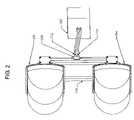
- FIG. 2is a side view of the dual antenna system according to the present invention.
- FIG. 3is a side view illustrating a normalized elevation pattern for the dual antenna system operating via the sum channel.
- FIG. 4is a side view illustrating a normalized elevation pattern for the dual antenna system operating via the difference channel.
- FIG. 5shows elevation patterns for both the sum channel and difference channel according to the present invention.
- FIGS. 1 and 2depict antenna system 100 according to an illustrative embodiment of the present invention.
- Antenna 102 and antenna 104are coupled to one another by connecting cables 106 and panel combiner 108 .
- Mounting structure 110is utilized to maintain proper alignment between antennas 102 and 104 and for mounting the dual antenna structure to the tower (not shown).
- Sum channel 112 and difference channel 114are provided on panel combiner 108 and are coupled to transceiver 202 .
- Transceiver 202comprises both a receiver and a transmitter.
- a 180° hybrid coupleris utilized as panel combiner 108 .
- Panel combiner 108is a reciprocal four-port device which outputs two equal amplitude in-phase signals from channels 116 and 118 when fed from sum channel 112 and two equal amplitude 180° out of phase signals when fed from difference channel 114 .
- signals input into channels 116 and 118will add at sum channel 112 and the difference of the two signals will appear at difference channel 114 .
- signals input into channels 116 and 118will add and appear at sum channel 112 while no signal will appear at difference channel 114 .
- the same input signalsare 180° out of phase with each other, all of the power will appear at difference channel 114 .
- FIGS. 3 and 4depict normalized antenna patterns for the angle diversity dual antenna system 100 according to the present invention.
- Antenna patternsdepict the gain of a signal transmitted or received by an antenna. The portion of the pattern showing directions of maximum response (or gain) are called “lobes,” and those showing minimum response are called “nulls”.
- An antenna's gainis usually specified as the gain of its main lobe.
- Antenna patternsusually take two forms, the elevation pattern and the azimuth pattern.
- the elevation patternis a graph of the cross section of the energy radiated from the antenna looking at it from the side.
- the azimuth patternis a graph of the cross section of the energy radiated from the antenna as if you were looking at it from directly above the antenna.
- Nondirectional antennashave equal gain to signals coming to them from all directions.
- Directional antennasare more responsive to signals coming from certain directions, and therefore, their gain changes based on direction.
- Antennasdiffer in their sensitivity or response to signals which they receive.
- a more sensitive antennais said to have more “gain” because it responds to signals which it intercepts by producing a greater signal output for the receiver than would an antenna with lower gain.
- FIG. 3depicts an elevation pattern when sum channel 112 of panel combiner 108 is used as the active channel.
- an elevation pattern having a single main lobeis produced.
- the single main lobeis produced due to antennas 102 and 104 being fed through sum channel 112 of panel combiner 108 .
- difference channel 114 of panel combiner 108is the active channel, an elevation pattern having two main lobes is produced due to the phase difference of difference channel 114 .
- antenna 102 and antenna 104are flat panel antennas in the general shape of an ellipse, approximately 5′ ⁇ 1′ in size, each panel comprising a 32 ⁇ 8 element array.
- the small size and low profile structure of antennas 102 and 104reduces wind loading problems that are common with antennas systems utilizing parabolic reflectors.
- Flat panel antennas 102 and 104are quite directional as they have most of their power radiated in one direction in both the vertical and horizontal planes.
- the elements of each arrayhave the same radiation patterns and polarization properties and are orientated in the same directions in space.
- antenna 102 and antenna 104each have a horizontal input 120 and a vertical input 122 .
- Horizontal input 120 and vertical input 122refer to the polarization of the propagating energy.
- the polarization for antenna system 100can be either horizontal or vertical.
- FIG. 1depicts antenna 102 and antenna 104 connected via horizontal input 120 .
- a maximum beamwidth of 2.2 degrees to the half-power point in elevationcan be achieved.
- a precise radiating element distribution in antennas 102 and 104yield the maximum beamwidth of 2.2 degrees to the half-power point in azimuth.
- the half-power beamwidthis a width measurement of the main lobe. This beamwidth meets FCC Category A requirements without requiring the complex structure associated with antennas having large parabolic reflectors.
- operating via sum channel 112produces a higher gain as compared with operating via difference channel 114 .
- a minimum amount of gainis necessary for satisfactory reception or transmission, it is not necessarily true that more gain is always better.
- an antenna pattern that is not concentrated in only one main lobeenables an antenna system to receive signals from a greater number of incoming directions.
- incoming signalsmay arrive at antennas 102 and 104 from different directions which may be in-phase or out of phase.
- difference channel 114 of panel combiner 108while in a receive mode, antenna system 100 will be able to receive signals over larger elevation angles.
- Incoming signals arriving at antenna 102 and antenna 104 which are completely in-phasewill be coupled from antennas 102 and 104 to sum channel 112 of panel combiner 108 .
- incoming signals arriving at antenna 102 and 104 which are 180° out of phasewill be coupled from antennas 102 and 104 to difference channel 114 of panel combiner 108 .
- transceiver 202is able to select the channel which supplies the greatest signal strength.
Landscapes
- Engineering & Computer Science (AREA)
- Computer Networks & Wireless Communication (AREA)
- Signal Processing (AREA)
- Variable-Direction Aerials And Aerial Arrays (AREA)
- Radio Transmission System (AREA)
Abstract
Description
1. Field of the Invention
The present invention relates to an antenna system utilized in line of sight communication links. More particularly, the present invention relates to a reduced size angle diversity antenna system used in line of sight communication links providing reduced windloading effects.
2. Related Art
In a line-of-sight communication system, long-distance terrestrial transmission of messages is accomplished via a series of relay points known as “hops.” Each hop consists of a tower and corresponding antenna, wherein a signal travels from one tower to a next tower, the signal being amplified before traveling between towers. The transmission is described as “line of sight”, and therefore, the antennas on a first tower must be visible from the antenna on the other tower.
Line-of-sight systems typically utilize antennas having large parabolic reflectors. In a receive mode, the parabolic reflector acts to collect a large area of a wavefront, and then focus the energy received in the wave back at the feed located at the antenna focal point. In a transmit mode, the reflector acts to accept radiated energy from the feedpoint and reflect the energy outward. The feed is known as a “microwave feedhorn” and is the part of the antenna that is held out in front the parabolic reflector.
The Federal Communications Commission (FCC) publishes technical standards for antennas operating in the transmit mode. These standards refer to each transmitting antenna licensed as a station on either end of a microwave point-to-point path. Category A standards apply to all stations operating in areas where certain microwave frequency bands are congested, or where there is a predictable risk of interference to other stations.
Large parabolic dish antennas provide adequate gain and directivity necessary to meet FCC Category A requirements but are burdened with complex structural problems. The manufacturing costs for feed structures of the parabolic antennas are quite high and the large physical structure of the parabolic antennas subjects the structure to very high wind loads.
For example, in a frequency range between 5.925 GHz and 6.425 GHz, a parabolic dish antenna having a diameter of approximately six feet is required to meet the FCC Category A requirements. An antenna of this size represents an area of over 28 square feet for wind load.
Signal fading is another known problem associated with the use of parabolic dish antennas. Fading occurs due to atmospheric conditions that cause bending of the signal path. This bending of the signal path makes the antenna to appear to be misaligned in the vertical direction.
Therefore, what is needed is a reduced sized line of sight antenna system that reduces the problems associated with parabolic dish antennas while maintaining the ability to meet FCC Category A requirements.
An innovative angle diversity antenna system utilizes a first antenna, a second antenna, and a panel combiner coupled to the first and second antenna. In a transmit mode, the first and second antenna are coupled to a transmit sum channel of the panel combiner. In a receive mode, the sum channel of the panel combiner and the difference channel of the panel combiner are connected to a receiver. The receiver selects the channel which supplies the greatest signal strength.
Angle diversity is utilized in the receive mode to reduce the effects of signal fading and a low profile structure for the first and second antennas acts to reduce problems associated with windloading. Thus, with proper spacing between the first and second antennas operating via the sum channel in a transmit mode, and choice of sum channel or difference channel in the receive mode, a reduced size antenna system is provided which is able to meet the FCC Category A requirements.
The above and other features of the invention including various and novel details of construction and combination of parts will now be more fully described with reference to the accompanying drawings and pointed out in the claims. It will be understood that the particular features embodying the invention are shown by way of illustration only and not as a limitation of the invention. The principles and features of this invention may be employed in varied and numerous embodiments without departing from the scope of the invention.
Aspects of illustrative, non-limiting embodiments of the present invention will become more apparent by describing in detail embodiments thereof with reference to the attached drawings in which:
The following description of illustrative non-limiting embodiments of the invention discloses specific configurations, features, and operations. However, the embodiments are merely examples of the present invention, and thus, the specific features described below are merely used to more easily describe such embodiments and to provide an overall understanding of the present invention.
Accordingly, one skilled in the art will readily recognize that the present invention is not limited to the specific embodiments described below. Furthermore, the description of various configurations, features, and operations of the present invention that are known to one skilled in the art are omitted for the sake of clarity and brevity. Also, it is to be understood that the phraseology and terminology employed herein is for the purpose of description and should not be regarded as limiting.
In an illustrative embodiment, a 180° hybrid coupler is utilized as panel combiner108. Panel combiner108 is a reciprocal four-port device which outputs two equal amplitude in-phase signals fromchannels sum channel 112 and two equal amplitude 180° out of phase signals when fed fromdifference channel 114.
Conversely, signals input intochannels sum channel 112 and the difference of the two signals will appear atdifference channel 114. Thus, if two identical signals are input intochannels sum channel 112 while no signal will appear atdifference channel 114. On the other hand, if the same input signals are 180° out of phase with each other, all of the power will appear atdifference channel 114.
Antenna patterns usually take two forms, the elevation pattern and the azimuth pattern. The elevation pattern is a graph of the cross section of the energy radiated from the antenna looking at it from the side. The azimuth pattern is a graph of the cross section of the energy radiated from the antenna as if you were looking at it from directly above the antenna.
Since electromagnetic energy propagates in the form of waves, it spreads out through space due to the phenomenon of diffraction. Individual waves combine both constructively and destructively to form a diffraction pattern that manifests itself in the main lobes and side lobes of the antenna. Nondirectional antennas have equal gain to signals coming to them from all directions. Directional antennas, on the other hand, are more responsive to signals coming from certain directions, and therefore, their gain changes based on direction.
Antennas differ in their sensitivity or response to signals which they receive. A more sensitive antenna is said to have more “gain” because it responds to signals which it intercepts by producing a greater signal output for the receiver than would an antenna with lower gain.
In an illustrative embodiment of the present invention,antenna 102 andantenna 104 are flat panel antennas in the general shape of an ellipse, approximately 5′×1′ in size, each panel comprising a 32×8 element array. The small size and low profile structure ofantennas
As shown inFIG. 1 ,antenna 102 andantenna 104 each have ahorizontal input 120 and avertical input 122.Horizontal input 120 andvertical input 122 refer to the polarization of the propagating energy. By providing bothhorizontal inputs 120 andvertical inputs 122, the polarization forantenna system 100 can be either horizontal or vertical. In an illustrative embodiment,FIG. 1 depictsantenna 102 andantenna 104 connected viahorizontal input 120.
By operatingantenna system 100 viasum channel 112 ofpanel combiner 108 while in the transmit mode, along with proper spacing betweenantennas antennas
As shown inFIG. 5 , operating viasum channel 112 produces a higher gain as compared with operating viadifference channel 114. Although a minimum amount of gain is necessary for satisfactory reception or transmission, it is not necessarily true that more gain is always better. For example, an antenna pattern that is not concentrated in only one main lobe enables an antenna system to receive signals from a greater number of incoming directions.
Problems associated with signal fading are addressed by enablingantenna system 100 to switch betweensum channel 112 anddifference channel 114 in a receive mode. By enablingdifference channel 114 to be selected in a receive mode, angle diversity is provided due to the elevation pattern having two main lobes as shown inFIG. 4 .
During a receive mode, incoming signals may arrive atantennas difference channel 114 ofpanel combiner 108 while in a receive mode,antenna system 100 will be able to receive signals over larger elevation angles.
Incoming signals arriving atantenna 102 andantenna 104 which are completely in-phase will be coupled fromantennas channel 112 ofpanel combiner 108. Conversely, incoming signals arriving atantenna antennas difference channel 114 ofpanel combiner 108.
Typically, however, signals will not arrive completely in phase or completely out-of-phase and thusantennas channel 112 and part of the signal todifference channel 114. By monitoringsum channel 112 anddifference channel 114, while in a receive mode,transceiver 202 is able to select the channel which supplies the greatest signal strength.
The previous description of embodiments is provided to enable a person skilled in the art to make and use the present invention. Moreover, various modifications to these embodiments will be readily apparent to those skilled in the art, and the generic principles and specific examples defined herein may be applied to other embodiments without the use of inventive faculty. For example, some or all of the features of the different embodiments discussed above may be combined into a single embodiment. Conversely, some of the features of a single embodiment discussed above may be deleted from the embodiment. Therefore, the present invention is not intended to be limited to the embodiments described herein but is to be accorded the widest scope as defined by the limitations of the claims and equivalents.
Claims (15)
1. An antenna system comprising:
a first antenna;
a second antenna disposed above the first antenna in a vertical plane; and
a combiner coupled to said first antenna and said second antenna that comprises a sum channel,
wherein said first antenna and said second antenna are separated by a predetermined distance in the vertical plane such that the first antenna and the second antenna operating via said sum channel provide a maximum beamwidth of 2.2 degrees to a half-power point in elevation.
2. The antenna system according toclaim 1 , wherein a transmit signal is coupled to the sum channel of said combiner during a transmit mode.
3. The antenna system according toclaim 2 , wherein an elevation pattern having one main lobe is formed when the transmit signal is coupled to the sum channel of said combiner.
4. The antenna system according toclaim 2 , wherein, during the transmit mode, said combiner outputs a first signal to said first antenna and a second signal to said second antenna, the first signal and the second signal being in-phase with one another,
wherein the first in-phase signal is output by said first antenna and the second in-phase signal is output by said second antenna, the signals output by said first antenna and said second antenna forming an elevation pattern having one main lobe.
5. The antenna system according toclaim 2 , wherein said combiner further comprises a difference channel.
6. The antenna system according toclaim 5 , further comprising a receiver,
wherein, during a receive mode, said first and second antenna couple received signals to said combiner,
wherein said receiver selects to receive signals on either the sum channel of said combiner or the difference channel of said combiner, the selection depending on whether the sum channel or the difference channel provides a stronger signal.
7. The antenna system according toclaim 6 , wherein an elevation pattern having one main lobe is produced if said receiver selects the sun-i channel during the receive mode.
8. The antenna system according toclaim 7 , wherein an elevation pattern having two main lobes is produced if said receiver selects the difference channel during the receive mode.
9. The antenna system according toclaim 6 , wherein said first and second antenna operating via the sum channel of said combiner provide a maximum beamwidth of 2.2 degrees to the half-power point in azimuth and elevation.
10. The antenna system according toclaim 9 , wherein the antenna system is capable of operating in a frequency range from approximately 5.925 GHz to 6.425 GHz.
11. The antenna system according toclaim 6 , wherein an elevation pattern having two main lobes is produced if said receiver selects the difference channel during the receive mode.
12. The antenna system according toclaim 1 , wherein said first antenna and said second antenna are flat panel antennas having an identical array of elements.
13. The antenna system according toclaim 12 , wherein said first and second antennas have a low-profile shape, thereby providing a reduced windload on said first and second antennas.
14. The antenna system according toclaim 12 , wherein each of said flat panel antennas comprises a 32×8 element array.
15. The antenna system according toclaim 1 , wherein the maximum beamwidth of 2.2 degrees to the half-power point in elevation is occurs at a frequency range from approximately 5.925 GHz to 6.425 GHz.
Priority Applications (3)
| Application Number | Priority Date | Filing Date | Title |
|---|---|---|---|
| US10/366,397US7099696B2 (en) | 2003-02-14 | 2003-02-14 | Angle diversity dual antenna system |
| EP04002405.1AEP1455412B1 (en) | 2003-02-14 | 2004-02-04 | Angle diversity dual antenna system |
| CN2004100042320ACN1521892B (en) | 2003-02-14 | 2004-02-12 | Angle diversity dual antenna system |
Applications Claiming Priority (1)
| Application Number | Priority Date | Filing Date | Title |
|---|---|---|---|
| US10/366,397US7099696B2 (en) | 2003-02-14 | 2003-02-14 | Angle diversity dual antenna system |
Publications (2)
| Publication Number | Publication Date |
|---|---|
| US20040160362A1 US20040160362A1 (en) | 2004-08-19 |
| US7099696B2true US7099696B2 (en) | 2006-08-29 |
Family
ID=32824683
Family Applications (1)
| Application Number | Title | Priority Date | Filing Date |
|---|---|---|---|
| US10/366,397Expired - LifetimeUS7099696B2 (en) | 2003-02-14 | 2003-02-14 | Angle diversity dual antenna system |
Country Status (3)
| Country | Link |
|---|---|
| US (1) | US7099696B2 (en) |
| EP (1) | EP1455412B1 (en) |
| CN (1) | CN1521892B (en) |
Cited By (1)
| Publication number | Priority date | Publication date | Assignee | Title |
|---|---|---|---|---|
| US20110215960A1 (en)* | 2010-03-08 | 2011-09-08 | Michael Stevens | Radio receiver |
Families Citing this family (2)
| Publication number | Priority date | Publication date | Assignee | Title |
|---|---|---|---|---|
| US10969415B2 (en) | 2016-09-16 | 2021-04-06 | Waterford Consultants Llc | RF antenna sector monitoring device and method |
| US12394303B1 (en) | 2024-03-22 | 2025-08-19 | Waterford Consultants, LLC | Systems for mitigating radio-frequency radiation exposure using power interrupters |
Citations (17)
| Publication number | Priority date | Publication date | Assignee | Title |
|---|---|---|---|---|
| US3864633A (en)* | 1972-08-23 | 1975-02-04 | Sperry Rand Corp | Angle diversity communication system |
| US4129874A (en) | 1977-09-19 | 1978-12-12 | The United States Of America As Represented By The Field Operations Bureau Of The Federal Communications Commission | Antenna pattern combiner |
| US4316192A (en) | 1979-11-01 | 1982-02-16 | The Bendix Corporation | Beam forming network for butler matrix fed circular array |
| US4564935A (en)* | 1984-01-10 | 1986-01-14 | The United States Of America As Represented By The Secretary Of The Air Force | Tropospheric scatter communication system having angle diversity |
| US4611212A (en) | 1981-09-14 | 1986-09-09 | Itt Corporation | Field component diversity antenna and receiver arrangement |
| US4914443A (en)* | 1988-07-26 | 1990-04-03 | At&T Bell Laboratories | Angle diversity signal separator using mode conversion |
| US5202700A (en) | 1988-11-03 | 1993-04-13 | Westinghouse Electric Corp. | Array fed reflector antenna for transmitting & receiving multiple beams |
| US5754140A (en)* | 1996-07-05 | 1998-05-19 | Sperry Marine Inc. | Beam sharpened, low sidelobe antenna system |
| US5784032A (en) | 1995-11-01 | 1998-07-21 | Telecommunications Research Laboratories | Compact diversity antenna with weak back near fields |
| US5880701A (en) | 1996-06-25 | 1999-03-09 | Pcs Solutions, Llc | Enclosed wireless telecommunications antenna |
| US5940044A (en) | 1998-01-22 | 1999-08-17 | Allen Telecom Inc. | 45 degree polarization diversity antennas |
| US5966102A (en) | 1995-12-14 | 1999-10-12 | Ems Technologies, Inc. | Dual polarized array antenna with central polarization control |
| US5969689A (en) | 1997-01-13 | 1999-10-19 | Metawave Communications Corporation | Multi-sector pivotal antenna system and method |
| US6150975A (en) | 1993-02-06 | 2000-11-21 | Thomson-Csf | Divergence measurement antenna for single-pulse radar |
| US6356242B1 (en) | 2000-01-27 | 2002-03-12 | George Ploussios | Crossed bent monopole doublets |
| US6404385B1 (en) | 1997-06-26 | 2002-06-11 | Alcatel | Telecommunication system antenna and method for transmitting and receiving using the antenna |
| EP1279234A2 (en) | 2000-05-05 | 2003-01-29 | Celletra Ltd. | System and method for providing polarization matching on a cellular communication forward link |
Family Cites Families (3)
| Publication number | Priority date | Publication date | Assignee | Title |
|---|---|---|---|---|
| GB2039187A (en)* | 1978-12-26 | 1980-07-30 | Ford Aerospace & Communication | Monopulse radar apparatus |
| GB2135828B (en)* | 1983-02-24 | 1986-03-05 | Cossor Electronics Ltd | A monopulse radar antenna |
| US6661366B2 (en)* | 2001-06-15 | 2003-12-09 | Lockheed Martin Corporation | Adaptive digital sub-array beamforming and deterministic sum and difference beamforming, with jamming cancellation and monopulse ratio preservation |
- 2003
- 2003-02-14USUS10/366,397patent/US7099696B2/ennot_activeExpired - Lifetime
- 2004
- 2004-02-04EPEP04002405.1Apatent/EP1455412B1/ennot_activeExpired - Lifetime
- 2004-02-12CNCN2004100042320Apatent/CN1521892B/ennot_activeExpired - Lifetime
Patent Citations (17)
| Publication number | Priority date | Publication date | Assignee | Title |
|---|---|---|---|---|
| US3864633A (en)* | 1972-08-23 | 1975-02-04 | Sperry Rand Corp | Angle diversity communication system |
| US4129874A (en) | 1977-09-19 | 1978-12-12 | The United States Of America As Represented By The Field Operations Bureau Of The Federal Communications Commission | Antenna pattern combiner |
| US4316192A (en) | 1979-11-01 | 1982-02-16 | The Bendix Corporation | Beam forming network for butler matrix fed circular array |
| US4611212A (en) | 1981-09-14 | 1986-09-09 | Itt Corporation | Field component diversity antenna and receiver arrangement |
| US4564935A (en)* | 1984-01-10 | 1986-01-14 | The United States Of America As Represented By The Secretary Of The Air Force | Tropospheric scatter communication system having angle diversity |
| US4914443A (en)* | 1988-07-26 | 1990-04-03 | At&T Bell Laboratories | Angle diversity signal separator using mode conversion |
| US5202700A (en) | 1988-11-03 | 1993-04-13 | Westinghouse Electric Corp. | Array fed reflector antenna for transmitting & receiving multiple beams |
| US6150975A (en) | 1993-02-06 | 2000-11-21 | Thomson-Csf | Divergence measurement antenna for single-pulse radar |
| US5784032A (en) | 1995-11-01 | 1998-07-21 | Telecommunications Research Laboratories | Compact diversity antenna with weak back near fields |
| US5966102A (en) | 1995-12-14 | 1999-10-12 | Ems Technologies, Inc. | Dual polarized array antenna with central polarization control |
| US5880701A (en) | 1996-06-25 | 1999-03-09 | Pcs Solutions, Llc | Enclosed wireless telecommunications antenna |
| US5754140A (en)* | 1996-07-05 | 1998-05-19 | Sperry Marine Inc. | Beam sharpened, low sidelobe antenna system |
| US5969689A (en) | 1997-01-13 | 1999-10-19 | Metawave Communications Corporation | Multi-sector pivotal antenna system and method |
| US6404385B1 (en) | 1997-06-26 | 2002-06-11 | Alcatel | Telecommunication system antenna and method for transmitting and receiving using the antenna |
| US5940044A (en) | 1998-01-22 | 1999-08-17 | Allen Telecom Inc. | 45 degree polarization diversity antennas |
| US6356242B1 (en) | 2000-01-27 | 2002-03-12 | George Ploussios | Crossed bent monopole doublets |
| EP1279234A2 (en) | 2000-05-05 | 2003-01-29 | Celletra Ltd. | System and method for providing polarization matching on a cellular communication forward link |
Cited By (1)
| Publication number | Priority date | Publication date | Assignee | Title |
|---|---|---|---|---|
| US20110215960A1 (en)* | 2010-03-08 | 2011-09-08 | Michael Stevens | Radio receiver |
Also Published As
| Publication number | Publication date |
|---|---|
| EP1455412B1 (en) | 2020-09-16 |
| CN1521892B (en) | 2011-04-27 |
| CN1521892A (en) | 2004-08-18 |
| EP1455412A2 (en) | 2004-09-08 |
| US20040160362A1 (en) | 2004-08-19 |
| EP1455412A3 (en) | 2004-11-24 |
Similar Documents
| Publication | Publication Date | Title |
|---|---|---|
| US11575214B2 (en) | Reflectarray antenna system | |
| US10116061B2 (en) | Beam steerable communication apparatus | |
| EP3120416B1 (en) | Compact antenna array using virtual rotation of radiating vectors | |
| US9590300B2 (en) | Electronically beam-steerable antenna device | |
| US11569575B2 (en) | Low-complexity beam steering in array apertures | |
| US10333593B2 (en) | Systems and methods of antenna design for full-duplex line of sight transmission | |
| US9692489B1 (en) | Transceiver using novel phased array antenna panel for concurrently transmitting and receiving wireless signals | |
| US20100117922A1 (en) | Array antenna, radio communication apparatus, and array antenna control method | |
| US20160087349A1 (en) | Method and apparatus for forming beam in antenna array | |
| CN204029975U (en) | Dual feed dual polarization high directivity array antenna system | |
| US9912080B2 (en) | Multi-sector directive antenna | |
| US20070069962A1 (en) | Antenna system for a radiocommunication station, and radiocommunication station having such antenna system | |
| US12051857B2 (en) | High frequency system using a circular array | |
| US7099696B2 (en) | Angle diversity dual antenna system | |
| EP3618304B1 (en) | Radio communication device, radio reception device, and radio communication system | |
| WO2019170827A1 (en) | High efficiency e-band antenna system | |
| US6980170B2 (en) | Co-located antenna design | |
| US20190165488A1 (en) | Dual circular polarization diversity scheme for microwave link | |
| Nasr et al. | Active Windshield Antenna for 5G Applications | |
| JPH09214413A (en) | Wireless relay system | |
| CN111615775A (en) | Vertically polarized antennas and terminal equipment | |
| JPH04227132A (en) | Angle diversity antenna with phased array feed | |
| US5995056A (en) | Wide band tem fed phased array reflector antenna | |
| US7102583B1 (en) | Multi-band antenna having a reflector | |
| WO2009009533A1 (en) | Single input/output mesh antenna with linear array of cross polarity dipole radiating elements |
Legal Events
| Date | Code | Title | Description |
|---|---|---|---|
| AS | Assignment | Owner name:RADIO FREQUENCY SYSTEMS, INC., CONNECTICUT Free format text:ASSIGNMENT OF ASSIGNORS INTEREST;ASSIGNOR:LECUYER, FREDERIC;REEL/FRAME:013771/0498 Effective date:20030214 | |
| AS | Assignment | Owner name:RADIO FREQUENCY SYSTEMS, INC., CONNECTICUT Free format text:MERGER AND NAME CHANGE;ASSIGNORS:RADIO FREQUENCY SYSTEMS, INC.;ALCATEL NA CABLE SYSTEMS, INC.;REEL/FRAME:015370/0553 Effective date:20040624 | |
| STCF | Information on status: patent grant | Free format text:PATENTED CASE | |
| FPAY | Fee payment | Year of fee payment:4 | |
| FPAY | Fee payment | Year of fee payment:8 | |
| MAFP | Maintenance fee payment | Free format text:PAYMENT OF MAINTENANCE FEE, 12TH YEAR, LARGE ENTITY (ORIGINAL EVENT CODE: M1553) Year of fee payment:12 | |
| AS | Assignment | Owner name:RFS TECHNOLOGIES, INC., CONNECTICUT Free format text:CHANGE OF NAME;ASSIGNOR:RADIO FREQUENCY SYSTEMS, INC.;REEL/FRAME:064659/0966 Effective date:20230519 |