US7099354B2 - Method and apparatus for frequency and timing distribution through a packet-based network - Google Patents
Method and apparatus for frequency and timing distribution through a packet-based networkDownload PDFInfo
- Publication number
- US7099354B2 US7099354B2US10/132,086US13208602AUS7099354B2US 7099354 B2US7099354 B2US 7099354B2US 13208602 AUS13208602 AUS 13208602AUS 7099354 B2US7099354 B2US 7099354B2
- Authority
- US
- United States
- Prior art keywords
- timing
- peripheral
- timing element
- packet
- master
- Prior art date
- Legal status (The legal status is an assumption and is not a legal conclusion. Google has not performed a legal analysis and makes no representation as to the accuracy of the status listed.)
- Expired - Fee Related, expires
Links
- 238000000034methodMethods0.000titleclaimsdescription26
- 230000002093peripheral effectEffects0.000claimsabstractdescription136
- 230000004044responseEffects0.000claimsabstractdescription6
- 230000005540biological transmissionEffects0.000claimsdescription21
- 230000001934delayEffects0.000claimsdescription18
- 230000001360synchronised effectEffects0.000claimsdescription17
- 238000004891communicationMethods0.000claimsdescription3
- 238000005259measurementMethods0.000abstractdescription6
- 230000000903blocking effectEffects0.000description4
- 230000006870functionEffects0.000description4
- 238000010586diagramMethods0.000description3
- 230000000737periodic effectEffects0.000description3
- 230000008901benefitEffects0.000description2
- 230000000712assemblyEffects0.000description1
- 238000000429assemblyMethods0.000description1
- 230000015572biosynthetic processEffects0.000description1
- 125000004122cyclic groupChemical group0.000description1
- 238000001514detection methodMethods0.000description1
- 238000009434installationMethods0.000description1
- 238000012986modificationMethods0.000description1
- 230000004048modificationEffects0.000description1
- 230000011664signalingEffects0.000description1
- 238000006467substitution reactionMethods0.000description1
- 238000003786synthesis reactionMethods0.000description1
- 230000001960triggered effectEffects0.000description1
Images


Classifications
- H—ELECTRICITY
- H04—ELECTRIC COMMUNICATION TECHNIQUE
- H04J—MULTIPLEX COMMUNICATION
- H04J3/00—Time-division multiplex systems
- H04J3/02—Details
- H04J3/06—Synchronising arrangements
- H04J3/0635—Clock or time synchronisation in a network
- H04J3/0638—Clock or time synchronisation among nodes; Internode synchronisation
- H04J3/0658—Clock or time synchronisation among packet nodes
- H04J3/0661—Clock or time synchronisation among packet nodes using timestamps
- H04J3/0667—Bidirectional timestamps, e.g. NTP or PTP for compensation of clock drift and for compensation of propagation delays
Definitions
- This inventionrelates to the distribution of frequency and timing information over a packet-based network.
- the inventionmore particularly relates to apparatus and methods through which highly accurate frequency and phase synchronization can be achieved among various elements within a packet-based network using packets to distribute timing information.
- a method and apparatus for frequency distribution through a packet-based networkis provided.
- a methodfor synchronization between a master timing element and at least one peripheral timing element interconnected through a packet-based network.
- a timing packetis periodically transmitted from the master timing element according to a timing reference, where each peripheral timing element is coupled to receive the timing packets.
- an echo packetis transmitted to the master timing element from the same peripheral timing element.
- a loopback delayis then measured between the start of the transmission of the timing packet and the reception of a corresponding echo packet for each peripheral timing element.
- a plurality of loopback delay values corresponding to a peripheral timing elementare read over time and the lowest loopback delay value for the peripheral timing element is designated as the nonblocked loopback delay for that peripheral timing element. Then, a loop is locked in each peripheral timing element using only timing packets which incur a nonblocked loopback delay for the corresponding peripheral timing element as a reference.
- each echo packetis transmitted after a unique delay with respect to each peripheral timing element in order to reduce the likelihood of interblocking delays between echo packets.
- a loop phase from a locked loop of each peripheral timing elementis stored when a timing packet is received in each corresponding peripheral timing element.
- the loop phase minus the unique delay and minus one half the nonblocked loopback delayis designated as a phase reference for a peripheral timing element if the loop phase corresponds to a timing packet which incurred a nonblocked loopback delay value for the same peripheral timing element.
- a synchronous distributed system interconnected by a packet-based networkincludes a timing reference. Also included is a master timing element coupled to periodically transmit timing packets on the network according to the timing reference. Further included is at least one peripheral timing element coupled to receive the timing packets, each peripheral timing element being coupled to transmit an echo message on the network to the master timing element after a timing packet is received. Also included is a means to determine a loopback delay when each echo message is received by the master timing element, the loopback delay corresponding to each echo message included in a payload field of the following timing packet to be transmitted.
- each peripheral timing elementtransmits an echo message after a unique delay.
- the systemfurther includes means to designate a phase reference in each locked loop according to the reception of timing packets which incur a minimum loopback delay to a corresponding peripheral timing element minus one half of the minimum loopback delay.
- the systemis a distributed radio system, which includes at least one radio interface unit for wireless communication.
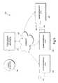
- FIG. 1is a diagram of a distributed electronic system using Ethernet packets for system synchronization.
- FIG. 2is a depiction of fields included in a timing packet.
- FIG. 3is a flow chart, which depicts the synchronization method employed within a peripheral timing element.
- FIG. 4is a flow chart, which depicts the synchronization method employed within the master timing element.
- FIG. 5is a diagram of a distributed radio system using Ethernet packets for system synchronization.
- FIG. 1is a diagram of a synchronous, frequency-locked distributed system ( 100 ) interconnected through a packet-based network.
- an alternative and substantially dedicated transmission mediumwas required apart from the primary Ethernet network transmission medium in order to transport a synchronization signal to the various system elements.
- the present inventioninterconnects the several elements only through standard Ethernet signaling using a minimum number of industry standard cable assemblies and interfaces to each system element. As will be described in more detail below, the present invention propagates timing and synchronization information to the system elements solely through the use of Ethernet packets.
- the present inventionaddresses the issue of Ethernet packets being difficult to use for the purpose of timing and synchronization.
- the difficultycomes from the fact that these types of packets are subject to unpredictable constant and stochastic delays through an Ethernet network, which will significantly degrade the degree to which the various system elements can be accurately synchronized.
- a time sensitive electronic systemsuch as a distributed radio system, in which several elements of the radio system are interconnected through an Ethernet network
- the unpredictable delays of an Ethernet network interfacewould generally be intolerable for the purposes of system synchronization.
- the synchronization signalis to be used as a time and frequency reference for slot and frame synchronization in a digital radio system or as a frequency reference for the synthesis of radio frequency (RF) carrier signals.
- RFradio frequency
- the synchronous distributed system ( 100 ) of the present inventionis interconnected through a packet-based network ( 105 ).
- a packet-based networkdoes not guarantee a particular amount of bandwidth for the transmission of data. Instead, the transmission and reception of data is bursty in nature because elements interfaced to the network are allowed to transmit data at arbitrary, unsynchronized intervals.
- the elements of the systemare synchronized to each other in phase and frequency such that various tasks and functions allocated among the system elements ( 110 , 120 , 130 , and 140 ) may be selectively executed in a substantially simultaneous manner or may be executed in a precise time sequence, relative to each other and also so that a frequency reference exists within each of the system elements ( 110 , 120 , 130 , and 140 ), in which all of the frequency references are substantially frequency-locked.
- two or more frequenciesare considered to be locked when they are related by a constant factor to the other frequencies.
- the synchronous frequency-locked distributed system ( 100 )includes one master timing element ( 110 ) and one or more peripheral timing elements ( 120 , 130 , and 140 ).
- the master timing element ( 110 )transmits timing packets to peripheral timing elements ( 120 , 130 , and 140 ) in a periodic manner in accordance with a timing or frequency reference ( 101 ).
- a timing or frequency reference101
- this discussionwill generally refer to an Ethernet ( 105 ) as the network medium.
- other network solutionssuch as a wireless LAN, may be used to interconnect the elements of the system ( 110 , 120 , 130 , and 140 ) without departing from the scope of the present invention.
- the timing packetsare transmitted to the peripheral timing elements ( 120 , 130 , and 140 ) as multicast or broadcast Ethernet packets.
- a timing packet transmitted from the master timing element ( 110 )will be subject to a particular delay as the packet propagates to each of the peripheral timing elements ( 120 , 130 , and 140 ).
- the precise propagation delay of a timing packetwill depend on the inherent or fixed delays associated with the network equipment with respect to a particular peripheral timing element ( 120 , 130 , or 140 ) and also will depend on the occurrence of “blocking” delays, in which the transmission of a timing packet is temporarily blocked while the transmission of another Ethernet packet is currently in progress. Consequently, the arrival time of a timing packet at any of the peripheral timing elements ( 120 , 130 , and 140 ) may be different and unpredictable.
- the peripheral timing elementWhen a timing packet is received by a particular peripheral timing element ( 120 , 130 , or 140 ), the peripheral timing element will respond with the transmission of an Ethernet echo message to the master timing element ( 110 ). Also included in the master timing element ( 110 ) is an echo timer ( 115 ) used to measure the elapsed time between the start of the transmission of a timing packet from the master timing element ( 110 ) and the receipt of an Ethernet echo message from any particular peripheral timing element ( 120 , 130 , or 140 ). The elapsed time described above is hereafter referred to as loopback delay.
- each timing packet transmitted by the master timing element ( 110 )includes one or more loopback delay values associated with the previous timing packet and corresponding echo messages from each peripheral timing element ( 120 , 130 , and 140 ).
- FIG. 2illustrates how such information can be organized in a timing packet.
- the timing packet depicted in FIG. 2includes a 48 byte destination media access control (MAC) address, a 48 byte source address, a 16 bit Ethernet type field and a 16 bit cyclic redundancy check (CRC) code as defined in the IEEE 803 Ethernet specification.
- the remaining field of the timing packet shown in FIG. 2is commonly referred to as the payload.
- MACmedia access control
- CRCcyclic redundancy check
- the payloadincludes the measured loopback delays associated with Ethernet echo messages received by the master timing element ( 110 ) from the peripheral timing elements ( 120 , 130 , and 140 ).
- the payload field depicted in FIG. 2also includes peripheral address fields used to correlate a particular loopback delay value with a particular peripheral timing element ( 120 , 130 , and 140 ).
- the timing packetcan incorporate either a broadcast, multicast, or unicast destination MAC address and can include loopback delay measurements for an arbitrary number of peripheral timing elements in the payload.
- a peripheral timing element120 , 130 , or 140
- the peripheral timing element120 , 130 , or 140
- the peripheral timing element120 , 130 , or 140
- the peripheral timing elementwill scan the payload field of the timing packet for a loopback delay measurement, which corresponds to that peripheral timing element ( 120 , 130 , or 140 ).
- a peripheral timing element120 , 130 , or 140
- the minimum loopback delay value detectedwill be designated as twice the fixed or “nonblocked” Ethernet path delay from the master timing element ( 110 ) to the peripheral timing element ( 120 , 130 , or 140 ).
- Each peripheral timing element ( 120 , 130 , and 140 )further includes a locked loop ( 121 , 131 , and 141 ), such as a phase-locked loop (PLL) or a frequency-locked loop (FLL), both of which are well known in the art. While a PLL is used as an example in this discussion, it is to be understood that the scope of the present invention includes both a PLL and an FLL.
- the locked loop ( 121 , 131 , and 141 ) included in each peripheral timing element ( 120 , 130 , and 140 respectively)is phase-locked to timing packets.
- Each PLL ( 121 , 131 , and 141 )includes a phase detector and a voltage controlled oscillator (VCO). Operation of each PLL ( 121 , 131 , and 141 ), in conjunction with a timing packet reference, is depicted in the flow chart in FIG. 3 . As shown in FIG. 3 , block ( 310 ) corresponds to an event in which a timing packet is received by a peripheral timing element ( 120 , 130 , or 140 ).
- the phase detector in the corresponding PLL( 121 , 131 , or 141 ) will compare the phase of each received timing packet with the phase of the VCO as indicated at block ( 320 ), and the peripheral timing element ( 120 , 130 , or 140 ) will examine the payload for a corresponding loopback delay measurement as indicated in block ( 340 ) and will transmit an echo message to the master timing element ( 110 ) as indicated in block ( 390 ).
- a decision step, indicated at block ( 360 )checks if the loopback delay is substantially equivalent to the minimum loopback delay.
- the stored results of the previous phase comparisonwill be applied to control the frequency of the VCO as required to achieve or retain a locked condition with respect to the timing packet, as depicted at block ( 370 ).
- the PLL included in each peripheral timing element120 , 130 , or 140 ) will be phase-locked only to timing packets which are associated with nonblocked Ethernet path delays, as discerned by the detection of corresponding nonblocked or minimum value loopback delays embedded in the timing packets.
- the reception of a timing packettriggers the execution of four task flow paths.
- the transmit echo message function ( 390 ) and the phase comparison function ( 320 )are executed simultaneously when a timing packet is received or are executed after a timing packet is received with respect to predictable and relatively constant delays.
- Each PLL or locked loop ( 121 , 131 , and 141 )has a loop phase. If the PLL ( 121 , 131 , or 141 ) includes a loop divider, then the phase of the loop divider and VCO together represent the loop phase. If the PLL ( 121 , 131 , or 141 ) does not include a loop divider, then the VCO phase alone represents the loop phase. If the PLL ( 121 , 131 , or 141 ) includes a loop divider having a relatively large value, then the phase of the loop divider is a close approximation of the loop phase. Some distributed systems require a phase reference that is substantially constant among the peripheral timing elements ( 120 , 130 , and 140 ).
- the loop phase of each PLL( 121 , 131 , and 141 ) is selectively marked or designated as a phase reference in conjunction with the arrival of timing packets with a minimum loopback delay.
- the current phase of a PLL( 121 , 131 , or 141 ) is stored when each timing packet is received by a corresponding peripheral timing element ( 120 , 130 , or 140 ) as shown at block ( 350 ) in FIG. 3 .
- the previously stored phase valueis used to set or designate a phase reference as shown at block ( 380 ). For example, if it were desired that a peripheral timing element ( 120 , 130 , or 140 ) have a phase reference that is coincident with the phase of the timing reference ( 111 ), then the phase reference would be designated as a previously stored phase value, which corresponds to a timing packet with a minimum loopback delay, minus half the minimum loopback delay.
- the loop phasewill be aligned with arrival of non-blocked timing packets.
- the phase referencewould be the loop phase minus half the minimum loopback delay.
- the synchronization method described aboveprovides an accurate distributed phase reference over a network, which compensates for the arbitrary nonblocked network path delay of the timing packets.
- each PLL ( 121 , and 141 )will maintain the distributed phase reference, in the present blocking delays, due to memory which is inherent in each PLL ( 121 , 131 , and 141 ).
- FIG. 4An example task flow for the transmission of timing packets by a master timing element ( 110 ) is shown in FIG. 4 .
- the occurrence of a reference-timing eventshown at block ( 410 ) triggers the transmission of a timing packet and clears the echo timer and previous loopback delay measurements, shown at blocks ( 420 , 430 and 440 ) respectively.
- the master timing element ( 110 )will then look for received echo messages as shown at block ( 450 ).
- the master timing element ( 110 )when an echo message is received from a peripheral timing element ( 120 , 130 , or 140 ), the master timing element ( 110 ) will use the current value of the echo timer to calculate a loopback delay, and will store the loopback delay to correspond with the associated peripheral timing element ( 120 , 130 , or 140 ). Each stored loopback delay is included in the payload of the following timing packet transmitted by the master timing element ( 110 ).
- each peripheral timing elementWhen a plurality of peripheral timing elements ( 120 , 130 , and 140 ) each receive a timing packet simultaneously, a plurality of echo messages may be transmitted to the master timing element ( 110 ) substantially simultaneously. In this condition, some echo messages may incur interblocking delays when received at the master timing element ( 110 ) due to the simultaneous arrival of other echo messages. In order to reduce the likelihood of echo messages blocking each other, each peripheral timing element is set to delay the transmission of an echo message, in response to the reception of a timing packet, by a unique time interval.
- the peripheral timing element ( 120 , 130 , or 140 )when a peripheral timing element ( 120 , 130 , or 140 ) first receives a timing packet, the peripheral timing element ( 120 , 130 , or 140 ) will immediately transmit an echo message to the master timing element ( 110 ).
- the peripheral timing element ( 120 , 130 , or 140 )When a peripheral timing element ( 120 , 130 , or 140 ) receives subsequent timing packets, the peripheral timing element ( 120 , 130 , or 140 ) will note the sequence number in which a corresponding loopback delay is positioned within the payload of the timing packet and will delay the transmission of an echo message according to the sequence number.
- the peripheral timing element ( 120 , 130 , and 140 )will subtract the added unique delay of the echo message in the corresponding loopback delay when setting the phase reference.
- each peripheral timing element ( 120 , 130 , and 140 )will transmit an echo message, in response to a received timing packet, after a unique interval in time, thereby minimizing the occurrence of
- the master timing element ( 110 )includes a delay reference frequency used to measure the loopback delays associated with peripheral elements ( 120 , 130 , and 140 ).
- each locked-loop ( 121 , 131 , and 141 )is configured to generate a local frequency equal to the delay reference frequency.
- each timing packetis sent as an Ethernet broadcast or multicast message from the master timing element ( 110 ) to the peripheral timing elements ( 121 , 131 , and 141 respectively) at a frequency which is lower than and derived from the frequency of the timing reference ( 101 ).
- the master timing element ( 110 )may include a master locked loop ( 111 ) used to lock to a timing reference ( 101 ) having a relatively low frequency.
- the master locked loop ( 111 )includes a loop divider in order to multiply the frequency of the timing reference ( 101 ) to a relatively higher delay reference frequency.
- the transmission of timing packets from the master timing element ( 110 )is triggered from the timing reference ( 101 ).
- the peripheral timing element ( 120 , 130 , or 140 )receives a timing packet, the peripheral timing element ( 120 , 130 , or 140 ) sends an echo message to the master timing element ( 110 ) after a unique delay, which is derived according to the local frequency in the peripheral timing element ( 120 , 130 , or 140 ).
- Each timing packetincludes a loopback delay value, as measured in accordance with the delay reference frequency in the master timing element ( 110 ), corresponding to each echo message received from the peripheral timing elements ( 120 , 130 , and 140 ).
- a peripheral timing element120 , 130 , or 140
- receives a timing packetit retrieves the associated loopback delay value from the payload and subtracts the respective unique delay value in order to determine the network loopback delay.
- a distributed radio system ( 500 )includes multiple system components interconnected through an Ethernet network ( 505 ).
- the distributed radio system ( 500 )includes at least one radio interface unit ( 520 , 530 , or 540 ), which includes means for wireless communication.
- the radio system network processor ( 510 )is coupled to send control information to the radio interface units ( 520 , 530 , and 540 ) as well as data to be transmitted by the radio interface units ( 520 , 530 , and 540 ) and to accept data received by the radio interface units ( 520 , 530 , and 540 ).
- each radio interface unit ( 520 , 530 , and 540 )generates at least one carrier signal in accordance with the timing reference ( 501 ).
- An accurate estimate of the phase and frequency of the timing reference ( 501 )is generated within each radio interface unit ( 520 , 530 , and 540 ) through the use of Ethernet timing packets transmitted by the radio system network processor ( 510 ) using the packet timing synchronization method described above, where the radio system network processor ( 510 ) includes equivalent master timing element ( 110 ) functionality and where the radio interface units ( 520 , 530 , and 540 ) include equivalent peripheral timing element ( 120 , 130 , and 140 ) functionality.
- Each radio interface unit ( 520 , 530 , and 540 )further includes a phase reference, which is synchronized relative to a phase reference within the radio system processor ( 510 ) through the use of the Ethernet timing packets using the method described herein.
- the present inventionenables a plurality of elements, interconnected through a packet-based network, to be accurately synchronized in phase and frequency through the use of periodic timing packets, which are used as a phase and frequency reference for a locked loop. In general, this is accomplished by first measuring a nonblocked loopback path delay and then using only periodic timing packets which incur the nonblocked loopback path delay as a frequency and phase reference. While the preceding description of the present invention has grouped certain functions into either the peripheral timing elements or the master timing element, one skilled in the art will recognize that many other combinations or groupings are possible. Numerous modifications, changes, variations, substitutions, and equivalents will occur to those skilled in the art without departing from the spirit and scope of the present invention as defined by the appended claims.
Landscapes
- Engineering & Computer Science (AREA)
- Computer Networks & Wireless Communication (AREA)
- Signal Processing (AREA)
- Synchronisation In Digital Transmission Systems (AREA)
Abstract
Description
Claims (20)
Priority Applications (2)
| Application Number | Priority Date | Filing Date | Title |
|---|---|---|---|
| US10/132,086US7099354B2 (en) | 2002-01-24 | 2002-04-24 | Method and apparatus for frequency and timing distribution through a packet-based network |
| US11/512,064US20070025399A1 (en) | 2002-01-24 | 2006-08-28 | Method and apparatus for frequency and timing distribution through a packet-based network |
Applications Claiming Priority (2)
| Application Number | Priority Date | Filing Date | Title |
|---|---|---|---|
| US35192102P | 2002-01-24 | 2002-01-24 | |
| US10/132,086US7099354B2 (en) | 2002-01-24 | 2002-04-24 | Method and apparatus for frequency and timing distribution through a packet-based network |
Related Child Applications (1)
| Application Number | Title | Priority Date | Filing Date |
|---|---|---|---|
| US11/512,064Continuation-In-PartUS20070025399A1 (en) | 2002-01-24 | 2006-08-28 | Method and apparatus for frequency and timing distribution through a packet-based network |
Publications (2)
| Publication Number | Publication Date |
|---|---|
| US20030137997A1 US20030137997A1 (en) | 2003-07-24 |
| US7099354B2true US7099354B2 (en) | 2006-08-29 |
Family
ID=26830084
Family Applications (1)
| Application Number | Title | Priority Date | Filing Date |
|---|---|---|---|
| US10/132,086Expired - Fee RelatedUS7099354B2 (en) | 2002-01-24 | 2002-04-24 | Method and apparatus for frequency and timing distribution through a packet-based network |
Country Status (1)
| Country | Link |
|---|---|
| US (1) | US7099354B2 (en) |
Cited By (6)
| Publication number | Priority date | Publication date | Assignee | Title |
|---|---|---|---|---|
| US20040003007A1 (en)* | 2002-06-28 | 2004-01-01 | Prall John M. | Windows management instrument synchronized repository provider |
| US20040100989A1 (en)* | 2002-11-21 | 2004-05-27 | Chiu Victor Y. | Data transmission system and method |
| US20060146884A1 (en)* | 2002-10-09 | 2006-07-06 | Acorn Packet Solutions, Llc | System and method for rate agile adaptive clocking in a packet-based network |
| US20070060166A1 (en)* | 2005-07-21 | 2007-03-15 | Nec Corporation | Traffic detection system and communication-quality monitoring system on a network |
| US20070281643A1 (en)* | 2006-05-30 | 2007-12-06 | Hitachi Kokusai Electric Inc. | Radio communication system and overhang station apparatus |
| US20090274326A1 (en)* | 2008-05-05 | 2009-11-05 | Qualcomm Incorporated | Synchronization of signals for multiple data sinks |
Families Citing this family (62)
| Publication number | Priority date | Publication date | Assignee | Title |
|---|---|---|---|---|
| US20050243857A1 (en)* | 2004-04-30 | 2005-11-03 | Padcom, Inc. | Simultaneously routing data over multiple wireless networks |
| US20050259589A1 (en)* | 2004-05-24 | 2005-11-24 | Metrobility Optical Systems Inc. | Logical services loopback |
| EP1854245A1 (en)* | 2005-03-02 | 2007-11-14 | Omicron Ceti AB | An accurate time distribution over asynchronous networks. |
| CN1866814B (en)* | 2005-05-17 | 2011-02-02 | 上海华为技术有限公司 | Clock locking method and its system |
| WO2006127994A2 (en)* | 2005-05-25 | 2006-11-30 | Radioframe Networks, Inc. | Pll with phase clipping and resynchronization |
| GB2443867A (en)* | 2006-03-21 | 2008-05-21 | Zarlink Semiconductor Ltd | Timing source with packet size controller providing a distribution of packet sizes |
| US8717911B2 (en) | 2006-06-30 | 2014-05-06 | Centurylink Intellectual Property Llc | System and method for collecting network performance information |
| US8194643B2 (en) | 2006-10-19 | 2012-06-05 | Embarq Holdings Company, Llc | System and method for monitoring the connection of an end-user to a remote network |
| US8488447B2 (en) | 2006-06-30 | 2013-07-16 | Centurylink Intellectual Property Llc | System and method for adjusting code speed in a transmission path during call set-up due to reduced transmission performance |
| US8000318B2 (en) | 2006-06-30 | 2011-08-16 | Embarq Holdings Company, Llc | System and method for call routing based on transmission performance of a packet network |
| US9094257B2 (en) | 2006-06-30 | 2015-07-28 | Centurylink Intellectual Property Llc | System and method for selecting a content delivery network |
| US7948909B2 (en) | 2006-06-30 | 2011-05-24 | Embarq Holdings Company, Llc | System and method for resetting counters counting network performance information at network communications devices on a packet network |
| US8289965B2 (en) | 2006-10-19 | 2012-10-16 | Embarq Holdings Company, Llc | System and method for establishing a communications session with an end-user based on the state of a network connection |
| US7765294B2 (en) | 2006-06-30 | 2010-07-27 | Embarq Holdings Company, Llc | System and method for managing subscriber usage of a communications network |
| US8458364B2 (en)* | 2006-08-02 | 2013-06-04 | Freescale Semiconductor, Inc. | Method for receiving and processing frames and a device having frame receiving and processing capabilities |
| US8130793B2 (en) | 2006-08-22 | 2012-03-06 | Embarq Holdings Company, Llc | System and method for enabling reciprocal billing for different types of communications over a packet network |
| US7843831B2 (en) | 2006-08-22 | 2010-11-30 | Embarq Holdings Company Llc | System and method for routing data on a packet network |
| US8224255B2 (en) | 2006-08-22 | 2012-07-17 | Embarq Holdings Company, Llc | System and method for managing radio frequency windows |
| US8144586B2 (en) | 2006-08-22 | 2012-03-27 | Embarq Holdings Company, Llc | System and method for controlling network bandwidth with a connection admission control engine |
| US8102770B2 (en) | 2006-08-22 | 2012-01-24 | Embarq Holdings Company, LP | System and method for monitoring and optimizing network performance with vector performance tables and engines |
| US8407765B2 (en) | 2006-08-22 | 2013-03-26 | Centurylink Intellectual Property Llc | System and method for restricting access to network performance information tables |
| US8619600B2 (en) | 2006-08-22 | 2013-12-31 | Centurylink Intellectual Property Llc | System and method for establishing calls over a call path having best path metrics |
| US7684332B2 (en) | 2006-08-22 | 2010-03-23 | Embarq Holdings Company, Llc | System and method for adjusting the window size of a TCP packet through network elements |
| US8576722B2 (en) | 2006-08-22 | 2013-11-05 | Centurylink Intellectual Property Llc | System and method for modifying connectivity fault management packets |
| US9479341B2 (en) | 2006-08-22 | 2016-10-25 | Centurylink Intellectual Property Llc | System and method for initiating diagnostics on a packet network node |
| US7940735B2 (en) | 2006-08-22 | 2011-05-10 | Embarq Holdings Company, Llc | System and method for selecting an access point |
| US8307065B2 (en) | 2006-08-22 | 2012-11-06 | Centurylink Intellectual Property Llc | System and method for remotely controlling network operators |
| US8144587B2 (en) | 2006-08-22 | 2012-03-27 | Embarq Holdings Company, Llc | System and method for load balancing network resources using a connection admission control engine |
| US8537695B2 (en) | 2006-08-22 | 2013-09-17 | Centurylink Intellectual Property Llc | System and method for establishing a call being received by a trunk on a packet network |
| US8107366B2 (en) | 2006-08-22 | 2012-01-31 | Embarq Holdings Company, LP | System and method for using centralized network performance tables to manage network communications |
| US8064391B2 (en) | 2006-08-22 | 2011-11-22 | Embarq Holdings Company, Llc | System and method for monitoring and optimizing network performance to a wireless device |
| US8199653B2 (en) | 2006-08-22 | 2012-06-12 | Embarq Holdings Company, Llc | System and method for communicating network performance information over a packet network |
| US8223655B2 (en) | 2006-08-22 | 2012-07-17 | Embarq Holdings Company, Llc | System and method for provisioning resources of a packet network based on collected network performance information |
| US8274905B2 (en) | 2006-08-22 | 2012-09-25 | Embarq Holdings Company, Llc | System and method for displaying a graph representative of network performance over a time period |
| US8194555B2 (en) | 2006-08-22 | 2012-06-05 | Embarq Holdings Company, Llc | System and method for using distributed network performance information tables to manage network communications |
| US8015294B2 (en) | 2006-08-22 | 2011-09-06 | Embarq Holdings Company, LP | Pin-hole firewall for communicating data packets on a packet network |
| US8098579B2 (en) | 2006-08-22 | 2012-01-17 | Embarq Holdings Company, LP | System and method for adjusting the window size of a TCP packet through remote network elements |
| US8743703B2 (en) | 2006-08-22 | 2014-06-03 | Centurylink Intellectual Property Llc | System and method for tracking application resource usage |
| US7808918B2 (en) | 2006-08-22 | 2010-10-05 | Embarq Holdings Company, Llc | System and method for dynamically shaping network traffic |
| US8238253B2 (en)* | 2006-08-22 | 2012-08-07 | Embarq Holdings Company, Llc | System and method for monitoring interlayer devices and optimizing network performance |
| US8750158B2 (en) | 2006-08-22 | 2014-06-10 | Centurylink Intellectual Property Llc | System and method for differentiated billing |
| US8040811B2 (en) | 2006-08-22 | 2011-10-18 | Embarq Holdings Company, Llc | System and method for collecting and managing network performance information |
| US7590061B2 (en)* | 2006-08-22 | 2009-09-15 | Brilliant Telecommunications, Inc. | Apparatus and method of controlled delay packet forwarding |
| US8125897B2 (en) | 2006-08-22 | 2012-02-28 | Embarq Holdings Company Lp | System and method for monitoring and optimizing network performance with user datagram protocol network performance information packets |
| US8189468B2 (en) | 2006-10-25 | 2012-05-29 | Embarq Holdings, Company, LLC | System and method for regulating messages between networks |
| US8228791B2 (en) | 2006-08-22 | 2012-07-24 | Embarq Holdings Company, Llc | System and method for routing communications between packet networks based on intercarrier agreements |
| US7889660B2 (en)* | 2006-08-22 | 2011-02-15 | Embarq Holdings Company, Llc | System and method for synchronizing counters on an asynchronous packet communications network |
| US8549405B2 (en) | 2006-08-22 | 2013-10-01 | Centurylink Intellectual Property Llc | System and method for displaying a graphical representation of a network to identify nodes and node segments on the network that are not operating normally |
| US8531954B2 (en) | 2006-08-22 | 2013-09-10 | Centurylink Intellectual Property Llc | System and method for handling reservation requests with a connection admission control engine |
| US8111692B2 (en) | 2007-05-31 | 2012-02-07 | Embarq Holdings Company Llc | System and method for modifying network traffic |
| US8463881B1 (en) | 2007-10-01 | 2013-06-11 | Apple Inc. | Bridging mechanism for peer-to-peer communication |
| US8068425B2 (en) | 2008-04-09 | 2011-11-29 | Embarq Holdings Company, Llc | System and method for using network performance information to determine improved measures of path states |
| US8031747B2 (en) | 2009-04-29 | 2011-10-04 | Juniper Networks, Inc. | Apparatus and method of compensating for clock frequency and phase variations by processing packet delay values |
| KR101758968B1 (en) | 2010-06-30 | 2017-07-17 | 애플 인크. | Circuitry for active cable |
| US8327536B2 (en) | 2010-06-30 | 2012-12-11 | Apple Inc. | Method of manufacturing high-speed connector inserts and cables |
| US9112310B2 (en) | 2010-06-30 | 2015-08-18 | Apple Inc. | Spark gap for high-speed cable connectors |
| US20120226774A1 (en) | 2011-02-23 | 2012-09-06 | Apple Inc. | Display snooping |
| CN102208958B (en)* | 2011-07-04 | 2012-12-19 | 瑞斯康达科技发展股份有限公司 | Clock synchronization method for synchronous Ethernets, as well as synchronous information sending/receiving method, device and apparatus |
| CN103441810B (en)* | 2013-07-11 | 2016-03-16 | 盛科网络(苏州)有限公司 | The Ethernet frequency synchronization method of many time-domains and device |
| DE102016107629A1 (en)* | 2016-04-25 | 2017-10-26 | Schaffner International AG | Device for synchronization via an Ethernet interface |
| MX2018014751A (en)* | 2016-06-08 | 2019-04-29 | Sony Corp | Reception device, transmission device, and data processing method. |
| US20240378149A1 (en)* | 2023-05-11 | 2024-11-14 | Samsung Electronics Co., Ltd. | Systems and methods for synchronous cell switching for scalable memory |
Citations (7)
| Publication number | Priority date | Publication date | Assignee | Title |
|---|---|---|---|---|
| US4063220A (en) | 1975-03-31 | 1977-12-13 | Xerox Corporation | Multipoint data communication system with collision detection |
| US5566180A (en)* | 1994-12-21 | 1996-10-15 | Hewlett-Packard Company | Method for recognizing events and synchronizing clocks |
| US20010002196A1 (en)* | 1998-08-19 | 2001-05-31 | Path 1 Network Technologies, Inc., California Corporation | Methods and apparatus for providing quality of service guarantees in computer networks |
| US6373834B1 (en)* | 1997-12-19 | 2002-04-16 | Telefonaktiebolaget Lm Ericsson | Synchronization for cellular telecommunications network |
| US6665316B1 (en)* | 1998-09-29 | 2003-12-16 | Agilent Technologies, Inc. | Organization of time synchronization in a distributed system |
| US6665308B1 (en)* | 1995-08-25 | 2003-12-16 | Terayon Communication Systems, Inc. | Apparatus and method for equalization in distributed digital data transmission systems |
| US6816510B1 (en)* | 2000-02-09 | 2004-11-09 | Koninklijke Philips Electronics N.V. | Method for clock synchronization between nodes in a packet network |
- 2002
- 2002-04-24USUS10/132,086patent/US7099354B2/ennot_activeExpired - Fee Related
Patent Citations (7)
| Publication number | Priority date | Publication date | Assignee | Title |
|---|---|---|---|---|
| US4063220A (en) | 1975-03-31 | 1977-12-13 | Xerox Corporation | Multipoint data communication system with collision detection |
| US5566180A (en)* | 1994-12-21 | 1996-10-15 | Hewlett-Packard Company | Method for recognizing events and synchronizing clocks |
| US6665308B1 (en)* | 1995-08-25 | 2003-12-16 | Terayon Communication Systems, Inc. | Apparatus and method for equalization in distributed digital data transmission systems |
| US6373834B1 (en)* | 1997-12-19 | 2002-04-16 | Telefonaktiebolaget Lm Ericsson | Synchronization for cellular telecommunications network |
| US20010002196A1 (en)* | 1998-08-19 | 2001-05-31 | Path 1 Network Technologies, Inc., California Corporation | Methods and apparatus for providing quality of service guarantees in computer networks |
| US6665316B1 (en)* | 1998-09-29 | 2003-12-16 | Agilent Technologies, Inc. | Organization of time synchronization in a distributed system |
| US6816510B1 (en)* | 2000-02-09 | 2004-11-09 | Koninklijke Philips Electronics N.V. | Method for clock synchronization between nodes in a packet network |
Non-Patent Citations (3)
| Title |
|---|
| Cristian, F., "A Probabilistic Approach to Distributed Clock Synchronization," Proceedings 9th International Conference on Distributed Computing Systems, IEEE, Newport Beach, California, Jun. 5-9, 1989, pp. 288-296. |
| Cristian, F., and C. Fetzer, "Probabilistic Internal Clock Synchronization," Proceedings of the Thirteenth Symposium on Reliable Distributed Systems, IEEE, Dana Point, California, Oct. 25-27, 1994 (Dec. 6, 1995, version). |
| Mills, D.L., "Network Time Protocol (Version 3) Specification, Implementation and Analysis," Network Working Group Report RFC-1305, University of Delaware, Mar. 1992. |
Cited By (11)
| Publication number | Priority date | Publication date | Assignee | Title |
|---|---|---|---|---|
| US20040003007A1 (en)* | 2002-06-28 | 2004-01-01 | Prall John M. | Windows management instrument synchronized repository provider |
| US20060146884A1 (en)* | 2002-10-09 | 2006-07-06 | Acorn Packet Solutions, Llc | System and method for rate agile adaptive clocking in a packet-based network |
| US7684413B2 (en)* | 2002-10-09 | 2010-03-23 | Juniper Networks, Inc. | System and method for rate agile adaptive clocking in a packet-based network |
| US20040100989A1 (en)* | 2002-11-21 | 2004-05-27 | Chiu Victor Y. | Data transmission system and method |
| US7668092B2 (en)* | 2002-11-21 | 2010-02-23 | Honeywell International Inc. | Data transmission system and method |
| US20070060166A1 (en)* | 2005-07-21 | 2007-03-15 | Nec Corporation | Traffic detection system and communication-quality monitoring system on a network |
| US20070281643A1 (en)* | 2006-05-30 | 2007-12-06 | Hitachi Kokusai Electric Inc. | Radio communication system and overhang station apparatus |
| US7680095B2 (en)* | 2006-05-30 | 2010-03-16 | Hitachi Kokusai Electric Inc. | Radio communication system and overhang station apparatus |
| US20090274326A1 (en)* | 2008-05-05 | 2009-11-05 | Qualcomm Incorporated | Synchronization of signals for multiple data sinks |
| US8654988B2 (en) | 2008-05-05 | 2014-02-18 | Qualcomm Incorporated | Synchronization of signals for multiple data sinks |
| US9877130B2 (en) | 2008-05-05 | 2018-01-23 | Qualcomm Incorporated | Synchronization of signals for multiple data sinks |
Also Published As
| Publication number | Publication date |
|---|---|
| US20030137997A1 (en) | 2003-07-24 |
Similar Documents
| Publication | Publication Date | Title |
|---|---|---|
| US7099354B2 (en) | Method and apparatus for frequency and timing distribution through a packet-based network | |
| US7239626B2 (en) | System clock synchronization in an ad hoc and infrastructure wireless networks | |
| EP1223699B1 (en) | Method and system for providing time offset to minislot clock and count in headend devices | |
| JP3184464B2 (en) | Method and apparatus for supporting TDMA operation over a hybrid fiber coaxial (HFC) channel or other channel | |
| US5335357A (en) | Simulcast scheduler | |
| CN1934809B (en) | Method and apparatus for calibrating a time reference when separated by an unreliable data packet network | |
| US7792158B1 (en) | Media streaming synchronization | |
| US8401090B2 (en) | Video synchronization | |
| US6104729A (en) | Method and apparatus for synchronization of time stamping | |
| US6920155B2 (en) | Embedded loop delay compensation circuit for multi-channel transceiver | |
| US8149880B1 (en) | Media streaming synchronization | |
| US5613195A (en) | Burst output timing control system in satellite communication system | |
| US7471720B2 (en) | Frequency and timing synchronization and error correction in a satellite network | |
| US6275517B1 (en) | Wireless communication apparatus using frequency hopping, and method of controlling the apparatus | |
| US6714611B1 (en) | Wireless network with user clock synchronization | |
| US20070025399A1 (en) | Method and apparatus for frequency and timing distribution through a packet-based network | |
| US7424076B2 (en) | System and method for providing synchronization information to a receiver | |
| USRE38619E1 (en) | Method and apparatus for supporting TDMA operating over hybrid fiber coaxial (HFC) or other channels | |
| US20220385389A1 (en) | Signaling the distributed 1588v2 clock accuracy relative to UTC | |
| JPH11266217A (en) | Time division multiple access communication system, signal receiving method in time division multiple access communication system, and center device used in time division multiple access communication system | |
| FI108976B (en) | Procedure for synchronizing local real-time counters | |
| GB2243977A (en) | Synchronisation apparatus | |
| JPH0766805A (en) | Wireless communication system | |
| HK1014101B (en) | Method and apparatus for supporting tdma operation over hybrid fiber coaxial (hfc) or other channels | |
| GB2391751A (en) | Clock frequency correction in a mobile communications system |
Legal Events
| Date | Code | Title | Description |
|---|---|---|---|
| AS | Assignment | Owner name:RADIOFRAME NETWORKS, INC., WASHINGTON Free format text:ASSIGNMENT OF ASSIGNORS INTEREST;ASSIGNOR:KEATING, PIERCE V.;REEL/FRAME:013047/0992 Effective date:20020617 | |
| AS | Assignment | Owner name:ORIX VENTURE FINANCE LLC, NEW YORK Free format text:SECURITY AGREEMENT;ASSIGNOR:RADIOFRAME NETWORKS, INC.;REEL/FRAME:016167/0177 Effective date:20050609 | |
| AS | Assignment | Owner name:RADIOFRAME NETWORKS, INC., WASHINGTON Free format text:RELEASE BY SECURED PARTY;ASSIGNOR:ORIX VENTURE FINANCE LLC;REEL/FRAME:022845/0668 Effective date:20071212 | |
| AS | Assignment | Owner name:MOTOROLA, INC., ILLINOIS Free format text:ASSIGNMENT OF ASSIGNORS INTEREST;ASSIGNOR:RADIOFRAME NETWORKS, INC.;REEL/FRAME:023639/0026 Effective date:20091109 Owner name:MOTOROLA, INC.,ILLINOIS Free format text:ASSIGNMENT OF ASSIGNORS INTEREST;ASSIGNOR:RADIOFRAME NETWORKS, INC.;REEL/FRAME:023639/0026 Effective date:20091109 | |
| FPAY | Fee payment | Year of fee payment:4 | |
| AS | Assignment | Owner name:MOTOROLA MOBILITY, INC, ILLINOIS Free format text:ASSIGNMENT OF ASSIGNORS INTEREST;ASSIGNOR:MOTOROLA, INC;REEL/FRAME:025673/0558 Effective date:20100731 | |
| AS | Assignment | Owner name:MOTOROLA MOBILITY LLC, ILLINOIS Free format text:CHANGE OF NAME;ASSIGNOR:MOTOROLA MOBILITY, INC.;REEL/FRAME:029216/0282 Effective date:20120622 | |
| FPAY | Fee payment | Year of fee payment:8 | |
| AS | Assignment | Owner name:GOOGLE TECHNOLOGY HOLDINGS LLC, CALIFORNIA Free format text:ASSIGNMENT OF ASSIGNORS INTEREST;ASSIGNOR:MOTOROLA MOBILITY LLC;REEL/FRAME:034490/0001 Effective date:20141028 | |
| FEPP | Fee payment procedure | Free format text:MAINTENANCE FEE REMINDER MAILED (ORIGINAL EVENT CODE: REM.) | |
| LAPS | Lapse for failure to pay maintenance fees | Free format text:PATENT EXPIRED FOR FAILURE TO PAY MAINTENANCE FEES (ORIGINAL EVENT CODE: EXP.); ENTITY STATUS OF PATENT OWNER: LARGE ENTITY | |
| STCH | Information on status: patent discontinuation | Free format text:PATENT EXPIRED DUE TO NONPAYMENT OF MAINTENANCE FEES UNDER 37 CFR 1.362 | |
| FP | Lapsed due to failure to pay maintenance fee | Effective date:20180829 |