US7099160B1 - Card guide systems and devices - Google Patents
Card guide systems and devicesDownload PDFInfo
- Publication number
- US7099160B1 US7099160B1US10/698,329US69832903AUS7099160B1US 7099160 B1US7099160 B1US 7099160B1US 69832903 AUS69832903 AUS 69832903AUS 7099160 B1US7099160 B1US 7099160B1
- Authority
- US
- United States
- Prior art keywords
- card
- electronic equipment
- guides
- recited
- equipment rack
- Prior art date
- Legal status (The legal status is an assumption and is not a legal conclusion. Google has not performed a legal analysis and makes no representation as to the accuracy of the status listed.)
- Expired - Lifetime, expires
Links
Images


Classifications
- H—ELECTRICITY
- H05—ELECTRIC TECHNIQUES NOT OTHERWISE PROVIDED FOR
- H05K—PRINTED CIRCUITS; CASINGS OR CONSTRUCTIONAL DETAILS OF ELECTRIC APPARATUS; MANUFACTURE OF ASSEMBLAGES OF ELECTRICAL COMPONENTS
- H05K7/00—Constructional details common to different types of electric apparatus
- H05K7/14—Mounting supporting structure in casing or on frame or rack
- H05K7/1417—Mounting supporting structure in casing or on frame or rack having securing means for mounting boards, plates or wiring boards
- H05K7/1418—Card guides, e.g. grooves
- G—PHYSICS
- G06—COMPUTING OR CALCULATING; COUNTING
- G06F—ELECTRIC DIGITAL DATA PROCESSING
- G06F1/00—Details not covered by groups G06F3/00 - G06F13/00 and G06F21/00
- G06F1/16—Constructional details or arrangements
- G06F1/18—Packaging or power distribution
- G06F1/183—Internal mounting support structures, e.g. for printed circuit boards, internal connecting means
- G06F1/185—Mounting of expansion boards
Definitions
- This inventionis generally concerned with electronic equipment racks and related systems and devices. More specifically, embodiments of the present invention relate to card guides and card guide systems for removably retaining electronic modules within an electronic equipment rack.
- Electronic equipment enclosuresare used in a number of different industries and applications and generally serve to receive one or more pieces of electronic equipment and devices in such a way that the individual electronic components can operably interact with each other and/or with the electronic equipment enclosure.
- such electronic equipment enclosuresare configured to permit the use of one or more “plug-in” functional modules that electrically and mechanically interface with the electronic equipment enclosure and/or with other functional modules.
- many electronic equipment enclosuresinclude a chassis within which is disposed an internal structure configured to removably receive one or more functional modules in a desired arrangement.
- Such internal structuresare often referred to as “card cages.”
- the card cageis configured so that a user can define the functionality of the electronic equipment enclosure by selecting particular functional modules to be employed in the electronic equipment enclosure. In the event that it is desired to modify the functionality of a particular electronic equipment enclosure, such changes can be made simply by positioning additional functional modules in the card cage of the electronic equipment enclosure and/or by removing selected functional modules from the card cage of the electronic equipment enclosure.
- card cages and their constituent elementsenhance the flexibility and functionality of the associated electronic equipment enclosure, various problems nonetheless remain with conventional card cage systems, and especially card guides.
- Some exemplary problemsrelate to the fact that conventional card guides are typically retained in position within the chassis through the use of fasteners such as screws, pins, or bolts.
- each card guidemay require several fasteners in order to ensure that the card guide is securely positioned within the chassis.
- various types and sizes of fastenersmay be required to install a single card guide.
- conventional card guides and related systemsare often quite complicated and time-consuming to install. This aspect, at least, of conventional card cage systems tends to detract from the flexibility that the card cage otherwise lends to the electronic equipment rack, since the use of multiple and different fasteners makes it rather difficult to readily reconfigure the card cage should the need arise.
- a related concern with conventional card guidesrelates to the fact that the use of multiple fasteners to attach a card guide to the chassis necessarily requires that the card guide and the chassis each define complementary screw holes or similar openings into which the fastener must be inserted. This arrangement is problematic at least because it is often difficult to ensure that the various screw holes of the card guide and chassis are properly aligned for assembly. This problem is aggravated by the fact, noted earlier herein, that each card guide typically requires multiple fasteners for installation. Thus, the configuration and arrangement of typical card guides tends to complicate and impair the installation of the card guide in the chassis.
- card cages and card guidesthat can be quickly and readily aligned, and securely installed, in an electronic equipment chassis without requiring the use of fasteners. Further, such card cages and card guides should be configured so that they reliably maintain their position within the chassis once installed.
- embodiments of the inventionare concerned with card cage components, such as card guides, that can be readily and securely positioned within an electronic equipment chassis without requiring the use of fasteners.
- the card guidecomprises an element of a multi-part locking arrangement.
- This exemplary card guideincludes a plurality of integral engagement elements that are configured and arranged to releasably engage corresponding structure of an electronic equipment chassis.
- the integral engagement elementsare engaged with the corresponding structure of the electronic equipment chassis by snapping or pushing the engagement element into engagement with the corresponding structure.
- embodiments of the inventionenable ready and reliable installation and positioning of the card guide within the electronic equipment chassis. Further, embodiments of the invention are relatively simple to position and install since no fasteners are required for installation.
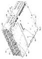
- FIG. 1is an exploded perspective view of an exemplary operating environment for embodiments of the invention
- FIG. 2is a detailed perspective view of an exemplary implementation of a card guide
- FIG. 3is a side view illustrating an exemplary implementation of a card guide as installed in an electronic equipment chassis
- FIG. 3Ais a detail taken from FIG. 3 and illustrating aspects of the relation between the bottom portion of an exemplary card guide and an electronic equipment chassis;
- FIG. 3Bis a detail taken from FIG. 3 and illustrating aspects of the relation between the top portion of an exemplary card guide and an electronic equipment chassis;
- FIG. 3Cis a detail taken from FIG. 3 and illustrating aspects of the relation between the rear portion of an exemplary card guide and an electronic equipment chassis;
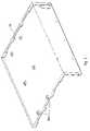
- FIG. 4is a perspective view illustrating further aspects of the interaction and relation between an exemplary card guide and corresponding structure of the bottom and rear portions of an electronic equipment chassis;
- FIG. 5a perspective view illustrating further aspects of corresponding structure of the bottom and rear portions of an electronic equipment chassis.
- an electronic equipment rack 100is indicated that generally comprises a housing 102 having a floor 102 A and being configured to be removably attached to a cover 104 .
- a backplane 106is interposed between the housing 102 and the cover 104 and includes connectors 106 A that mechanically and electrically interface with functional modules 400 (see FIG. 3 ) positioned within the electronic equipment rack 100 .
- housing 102may be collectively referred to herein as comprising an “electronic equipment chassis,” or simply “chassis.”
- chassiselectronic equipment chassis
- the exemplary chassis arrangements disclosed hereinshould not be construed to limit the scope of the invention in any way.
- a printed circuit board (“PCB”) assembly 108is positioned within the space collectively defined by the housing 102 , cover 106 and backplane 106 .
- exemplary PCB assembliesinclude various connectors 108 A and circuitry 108 B attached either directly or indirectly to a PCB 108 C.
- the PCB 108 Cdefines various structural elements or configurations, such as openings 108 D for example, configured and arranged to interact with a card guide 200 , as discussed in further detail below.
- the backplane 106may likewise define, or otherwise include, various structural elements or configurations, such as openings 106 B configured and arranged to interact with a card guide.
- the cover 104may also define such openings or, alternatively, may include engagement elements 104 A configured and arranged to receive, or otherwise engage, portions of the card guide 200 .
- the engagement elements 104 Amay be integral with the cover 104 or, alternatively, may comprise discrete structural elements connected to the cover 104 .
- the floor 102 Amay likewise define, or otherwise include, various structural elements or configurations configured and arranged to interact with a card guide 200 .
- exemplary structural elements or configurationssuch as openings 106 B and 108 D, as well as engagement elements 104 A, may be referred to herein, individual or collectively, as “corresponding structure” of an electronic equipment chassis.
- one or more card guides 200are further provided that act to removably receive one or more functional modules 400 (see FIG. 3 ) in various arrangements within the electronic equipment rack 100 .
- the card guides 200are configured to be removably, or permanently in some cases, installed within the electronic equipment rack without necessitating the use of fasteners to effect and maintain such installation.
- exemplary embodiments of card guides 200may be referred to herein as comprising a “fastenerless” construction.
- the card guides 200generally include one or more engagement elements 202 positioned at various locations on the card guide 200 and configured and arranged to removably engage, or otherwise interact with, the corresponding structure of the chassis.
- exemplary implementations of the engagement elements 202 , or equivalent structure, and the corresponding structure of the chassismay be collectively referred to herein as a “fastenerless connection system.”
- fastenerless connection systemand the engagement elements, it should further be noted that, in some implementations of the invention, an arrangement conceptually the reverse of that illustrated in FIG. 1 , for example, is implemented.
- the engagement elementscomprise a portion of the chassis instead of the card guide 200 while, on the other hand, the card guides 200 define various structural elements or configurations analogous to, for example, engagement elements 104 A and/or openings 106 B.
- the PCB 108may be designed to include structural elements that are configured to be received within an opening defined by the card guide 200 . Accordingly, the scope of the invention should not be construed to be limited to the disclosed exemplary embodiments. Further details concerning the card guides 200 , as well as engagement elements 202 and their interaction with the chassis, are provided below in connection with the discussion of FIGS. 2 through 5 .
- the engagement elements 202comprise but one exemplary structural implementation of a means for implementing a fastenerless connection. Any other structural configuration and arrangement of comparable functionality may likewise be employed however, and the scope of the invention should not be construed to be limited to the exemplary implementations disclosed herein.
- openingssuch as 106 B and 108 D
- openingsare configured to present an adequate “target” so that an assembly can readily engage the opening with the engagement element, notwithstanding some initial misalignment between the two.
- exemplary embodiments of the engagement elementsare relatively smaller than the openings and are configured with rounded edges and/or other structural features designed to reduce the likelihood of the engagement element sticking or binding with the opening during installation of the card guide.
- one exemplary engagement element 306 Bmay include a tapered upper portion that can be readily aligned with, inserted in, engagement structure 104 A of the cover 104 .
- Other structural features of comparable functionalitymay likewise be employed.
- Exemplary card guides 300may be constructed of a wide variety of materials such as, but not limited to, injection-molded polycarbonate materials such as Lexan®, or a carbon-fiber/polytetrafluoroethylene (“PTFE”), where the PTFE exemplarily comprises Teflon® material. Any other suitable materials, such as various types of plastics, may be employed however.
- the card guides 300are flame retardant and are constructed, configured and/or arranged to facilitate dissipation of charge buildups such as may contribute to static electricity-related problems.
- two or more card guides 300are disposed within the electronic equipment rack 100 so as to enable various arrangements of functional modules.
- Some card guide implementationsare further configured to operably interact with a removable adapter element (not shown) that lends a further degree of flexibility to card cage systems that include card guides 300 by allowing functional modules of various widths to be positioned within the electronic equipment rack 100 . More particularly, by selectively removing, and/or retaining, one or more adapter elements from the card cage, a user can quickly and easily customize the card guides to accommodate different combinations and arrangements of cards of various sizes. Further, the number of card guides 300 employed in any particular situation may be varied as necessary to suit the requirements of a desired arrangement of functional modules.
- Each card guide 300generally operates by restraining the engaged card of a functional module in two directions. First, the card is restrained from moving laterally in the direction of the width of the card. Second, the card is restrained from moving up or down in the direction perpendicular to the plane of the card. To do so, each card guide has at least one channel that is shaped to receive and engage a corresponding edge of the card.
- the exemplary card guide 300includes a body 301 that defines a channel 302 that runs substantially along the entire length of the card guide 300 and that is generally configured to slidingly receive a card edge.
- An end card guidetypically include a channel 302 on one side only, while a middle card guide typically defines a channel 302 on either side so as to accommodate opposing edges of adjacent cards.
- the height of the card guide 300may be varied depending upon the number of functional modules it is desired to stack within the electronic equipment rack 100 .
- the particular illustrated embodimentincludes two channels 302 separated by a web structure 304 that provides structural integrity to the system and that further restrains lateral motion of the card in the direction of the width of the card. The web structure 304 also insures sufficient clearance between two adjacent cards.
- the card guide 300includes, or otherwise defines, various engagement elements 306 A, 306 B and 306 C configured and arranged to engage, or otherwise interact with, corresponding structure of the electronic equipment rack 100 (see FIG. 1 ) chassis.
- the engagement elements 306 A, 306 B and 306 Care integral with the card guide 300 .
- engagement elements 306 A, 306 B and 306 Care configured and arranged to interact in a desired fashion with the chassis so as to enable the fastenerless connection of the card guide 300 to the electronic equipment rack 100 .
- engagement elements 306may be implemented in a wide variety of forms, configurations, and arrangements, depending upon the requirements of a particular application or operating environment. Further, the engagement elements 306 can be arranged on the card guide 300 so that a particular desired sequence of assembly is defined or implicated. Along the same lines, the engagement elements 306 can be configured and arranged on the card guide 300 so that incorrect installation of the card guide 300 and/or an improper card cage construction and installation sequence cannot be performed. Moreover, some implementations will admit of a number of different cage construction and installation sequences. Consistent with the foregoing, the scope of the invention is not limited to any particular type, configuration or arrangement of engagement elements. Rather, the disclosed embodiments are exemplary only
- implementations of the engagement elements 306serve to reduce, or eliminate, the various degrees of freedom of the card guide, relative to the chassis, and thereby allows the card guides 300 to be permanently, in some implementations at least, and securely interlocked with the chassis. Such an arrangement is useful where, for example, it is not possible, or desirable, to attach the card guides 300 to the chassis by using fasteners such as screws or bolts.
- FIGS. 3 through 5additional details are provided concerning aspects of the relation and interaction between exemplary implementations of the engagement elements 306 of card guide 300 with the chassis elements of the electronic equipment rack 100 .
- the configuration and arrangement of each of the exemplary engagement elements 306corresponds to the intended function of the engagement element and its relation to the chassis.
- an exemplary implementation of engagement element 306 Bgenerally comprises a foot-shaped configuration designed and arranged to slidingly engage, and be retained in, the opening 108 D defined by the PCB 108 .
- the opening 108 Dmay be designed so that the engagement element 306 B can only be inserted if tilted.
- the opening 108 Dmay be designed to enable the engagement element 306 B to be simply dropped in and slid into the position indicated in FIGS. 3 and 3A .
- each of the card guides 300is first attached to the PCB 108 by engaging the engagement element 306 B of the card guide 300 with the corresponding opening 108 D defined by the PCB 108 and advancing the card guide 300 until each engagement element 306 B reaches the end of the corresponding slot opening 108 D, as shown.
- the engagement element 306 Acomprises a generally tongue-shaped configuration arranged to be slidingly received within, and securely retained by, a corresponding engagement structure 104 A.
- the engagement element 306 Bis received within engagement structure 104 A illustrated in FIGS. 1 and 5 , in a snap-fit arrangement.
- One exemplary implementation of such an engagement structure 104 Ais the type “D” self-clinching tie mount, model number TD-175-12, produced by PEM® Fastening Systems.
- any other structural device or configuration of comparable functionalitymay alternatively be employed. Such structural devices and configurations may be referred to generally herein as a “self clinching tie mount.”
- the exemplary engagement element 306 Ccomprises a foot-like configuration arranged to slidingly engage, and be retained in, the opening 106 B defined by the backplane 106 .
- openings 106 B defined by the backplane 106 of the chassisreceive the engagement elements 306 C on the rear edge of the card guide 300 and the backplane 106 is, exemplarily, slid downwardly toward the PCB 108 until each openings 106 B end contacts the engagement elements 306 C of the corresponding card guide 300 , as shown.
- FIG. 4indicates an arrangement where three card guides 300 are engaged with the backplane 106 and housing 102 of the chassis. More specifically, in FIG. 4 , the engagement elements 306 B of the card guides 300 have been received and positioned in the corresponding openings 108 D defined by the PCB 108 . Further, the engagement elements 306 C of the card guides 300 have been received and positioned in the corresponding openings 106 A defined by the backplane 106 . The installation is completed by attachment of the cover 104 (see e.g., FIG. 3 ), so that all degrees of freedom of the card guides 300 are eliminated, thereby resulting in the stable and secure positioning of the card guides 300 .
- the engagement elements 306allow the card guide 300 to be removably attached to the chassis. Yet other implementations of the engagement elements 306 , such as engagement element 306 B for example, allow the card guide 300 to be permanently attached to the chassis.
- exemplary embodiments of the card guide, such as card guide 300may comprise a combination of engagement elements 306 where some engagement elements 306 are configured to permanently engage corresponding structure of the chassis, while other engagement elements 306 are configured to releasably engage corresponding structure of the chassis.
- Yet other embodiments of the card guide 300comprise only releasably engaging engagement elements 306 , or only permanently engaging engagement elements 306 . Accordingly, the scope of the invention should not be construed to be limited to the exemplary card guide 300 and engagement element 306 implementations disclosed herein.
Landscapes
- Engineering & Computer Science (AREA)
- Theoretical Computer Science (AREA)
- Computer Hardware Design (AREA)
- Power Engineering (AREA)
- Human Computer Interaction (AREA)
- Physics & Mathematics (AREA)
- General Engineering & Computer Science (AREA)
- General Physics & Mathematics (AREA)
- Microelectronics & Electronic Packaging (AREA)
- Mounting Of Printed Circuit Boards And The Like (AREA)
Abstract
Description
Claims (19)
Priority Applications (1)
| Application Number | Priority Date | Filing Date | Title |
|---|---|---|---|
| US10/698,329US7099160B1 (en) | 2002-10-31 | 2003-10-31 | Card guide systems and devices |
Applications Claiming Priority (2)
| Application Number | Priority Date | Filing Date | Title |
|---|---|---|---|
| US42261102P | 2002-10-31 | 2002-10-31 | |
| US10/698,329US7099160B1 (en) | 2002-10-31 | 2003-10-31 | Card guide systems and devices |
Publications (1)
| Publication Number | Publication Date |
|---|---|
| US7099160B1true US7099160B1 (en) | 2006-08-29 |
Family
ID=36915606
Family Applications (1)
| Application Number | Title | Priority Date | Filing Date |
|---|---|---|---|
| US10/698,329Expired - LifetimeUS7099160B1 (en) | 2002-10-31 | 2003-10-31 | Card guide systems and devices |
Country Status (1)
| Country | Link |
|---|---|
| US (1) | US7099160B1 (en) |
Cited By (21)
| Publication number | Priority date | Publication date | Assignee | Title |
|---|---|---|---|---|
| US20060044775A1 (en)* | 2004-08-31 | 2006-03-02 | Kabushiki Kaisha Toshiba | Case for electronic equipment and communication device |
| US20060215378A1 (en)* | 2004-11-10 | 2006-09-28 | Industrial Origami, Llc | Card guide for mounting printed circuit boards and the like to electronic equipment housings |
| US20070095774A1 (en)* | 2005-10-28 | 2007-05-03 | International Business Machines Corporation | Integrated frame and central electronic complex structure |
| US20080037218A1 (en)* | 2006-03-24 | 2008-02-14 | Sharma Viswa M | Modular chassis providing scalable mechanical, electrical and environmental functionality for MicroTCA and advanced TCA boards |
| US20100134989A1 (en)* | 2008-11-30 | 2010-06-03 | Dell Products L.P. | Expansion Card Retention Apparatus, Systems and Methods |
| US20100265645A1 (en)* | 2009-04-17 | 2010-10-21 | Inventec Corporation | Case of server |
| US7827442B2 (en) | 2006-01-23 | 2010-11-02 | Slt Logic Llc | Shelf management controller with hardware/software implemented dual redundant configuration |
| US20120008292A1 (en)* | 2010-07-08 | 2012-01-12 | Tyco Electronics Corporation | Card module and module connector assembly |
| US8114524B2 (en) | 2002-09-26 | 2012-02-14 | Industrial Origami, Inc. | Precision-folded, high strength, fatigue-resistant structures and sheet therefor |
| US8189599B2 (en) | 2005-08-23 | 2012-05-29 | Rpx Corporation | Omni-protocol engine for reconfigurable bit-stream processing in high-speed networks |
| US8267699B2 (en)* | 2009-06-12 | 2012-09-18 | Huawei Technologies Co., Ltd. | Backboard and communication device |
| USD676029S1 (en)* | 2012-06-15 | 2013-02-12 | Peerless Industries, Inc. | System for mounting audio/visual devices or the like from an overhead structure |
| US8438893B2 (en) | 2006-10-26 | 2013-05-14 | Industrial Origami, Inc. | Method of forming two-dimensional sheet material into three-dimensional structure |
| US8505258B2 (en) | 2000-08-17 | 2013-08-13 | Industrial Origami, Inc. | Load-bearing three-dimensional structure |
| USD702670S1 (en)* | 2009-03-26 | 2014-04-15 | Tait Towers Manufacturing, LLC | Video screen frame |
| US8936164B2 (en) | 2012-07-06 | 2015-01-20 | Industrial Origami, Inc. | Solar panel rack |
| FR3014637A1 (en)* | 2013-12-11 | 2015-06-12 | Enensys Technologies | CASE FOR AT LEAST ONE ELECTRONIC CARD |
| US10042396B1 (en)* | 2017-08-17 | 2018-08-07 | Cisco Technology, Inc. | Configurable module guides for modular electronic system |
| US10470335B2 (en) | 2017-08-17 | 2019-11-05 | Cisco Technology, Inc. | Configurable module guides for modular electronic system |
| EP4248530A4 (en)* | 2020-11-17 | 2024-05-22 | Tritium Holdings Pty Ltd | MODULAR ELECTRONICS ARRANGEMENT |
| US20250294698A1 (en)* | 2024-03-12 | 2025-09-18 | Hewlett Packard Enterprise Development Lp | Chassis of an information processing device having modular panel section |
Citations (18)
| Publication number | Priority date | Publication date | Assignee | Title |
|---|---|---|---|---|
| US4327835A (en)* | 1980-01-10 | 1982-05-04 | Honeywell Information Systems Inc. | Universal snap-in card guide for printed circuit card enclosures |
| US5666271A (en)* | 1995-09-19 | 1997-09-09 | Samsung Electronics Co., Ltd. | Rack for a communication system |
| US5912799A (en)* | 1996-07-01 | 1999-06-15 | Sun Microsystems, Inc. | Multiple disk drive storage enclosure with ventilation |
| US6038126A (en)* | 1999-04-21 | 2000-03-14 | Shin Jiuh Corp. | Electrical power supply assembly |
| US6166917A (en)* | 1998-01-07 | 2000-12-26 | 3Com Corporation | Techniques of assembling modular electronic equipment |
| US6195262B1 (en)* | 1998-04-01 | 2001-02-27 | International Business Machines Corporation | Low profile computer or communications network interconnecting device and housing therefor |
| US6198633B1 (en)* | 1998-04-01 | 2001-03-06 | International Business Machines Corporation | Computer system and enclosure thereof |
| US6205033B1 (en)* | 1998-06-19 | 2001-03-20 | Nortel Networks Limited | Electronic assembly circuit board guide apparatus |
| US6385053B1 (en) | 1999-02-26 | 2002-05-07 | Cisco Technology, Inc. | PCB vertical and horizontal guide |
| US6466449B1 (en) | 2001-08-01 | 2002-10-15 | Sun Microsystems, Inc. | Multi part disk cage apparatus |
| US6580616B2 (en) | 2001-10-16 | 2003-06-17 | Hewlett-Packard Company | Multiple circuit board adapter |
| US20040031767A1 (en)* | 2002-08-13 | 2004-02-19 | Ice Donald A. | Adapter element for card cage system |
| US20040032714A1 (en)* | 2002-08-13 | 2004-02-19 | Ice Donald A. | Functional module with card guide engagement feature |
| US20040032715A1 (en)* | 2002-08-13 | 2004-02-19 | Ice Donald A. | Electromagnetic radiation containment system |
| US20040037054A1 (en)* | 2002-08-13 | 2004-02-26 | Ice Donald A. | Card cage system |
| US6771513B2 (en)* | 2001-10-09 | 2004-08-03 | Daniel Measurement And Control, Inc. | Modular controller housing having movable card guides |
| US20040212973A1 (en)* | 2002-08-13 | 2004-10-28 | Ice Donald A. | Card cage system |
| US6999319B2 (en)* | 2004-04-06 | 2006-02-14 | Tatung Co., Ltd. | Support frame structure |
- 2003
- 2003-10-31USUS10/698,329patent/US7099160B1/ennot_activeExpired - Lifetime
Patent Citations (19)
| Publication number | Priority date | Publication date | Assignee | Title |
|---|---|---|---|---|
| US4327835A (en)* | 1980-01-10 | 1982-05-04 | Honeywell Information Systems Inc. | Universal snap-in card guide for printed circuit card enclosures |
| US5666271A (en)* | 1995-09-19 | 1997-09-09 | Samsung Electronics Co., Ltd. | Rack for a communication system |
| US5912799A (en)* | 1996-07-01 | 1999-06-15 | Sun Microsystems, Inc. | Multiple disk drive storage enclosure with ventilation |
| US6166917A (en)* | 1998-01-07 | 2000-12-26 | 3Com Corporation | Techniques of assembling modular electronic equipment |
| US6195262B1 (en)* | 1998-04-01 | 2001-02-27 | International Business Machines Corporation | Low profile computer or communications network interconnecting device and housing therefor |
| US6198633B1 (en)* | 1998-04-01 | 2001-03-06 | International Business Machines Corporation | Computer system and enclosure thereof |
| US6205033B1 (en)* | 1998-06-19 | 2001-03-20 | Nortel Networks Limited | Electronic assembly circuit board guide apparatus |
| US6385053B1 (en) | 1999-02-26 | 2002-05-07 | Cisco Technology, Inc. | PCB vertical and horizontal guide |
| US6038126A (en)* | 1999-04-21 | 2000-03-14 | Shin Jiuh Corp. | Electrical power supply assembly |
| US6466449B1 (en) | 2001-08-01 | 2002-10-15 | Sun Microsystems, Inc. | Multi part disk cage apparatus |
| US6771513B2 (en)* | 2001-10-09 | 2004-08-03 | Daniel Measurement And Control, Inc. | Modular controller housing having movable card guides |
| US6580616B2 (en) | 2001-10-16 | 2003-06-17 | Hewlett-Packard Company | Multiple circuit board adapter |
| US20040031767A1 (en)* | 2002-08-13 | 2004-02-19 | Ice Donald A. | Adapter element for card cage system |
| US20040032714A1 (en)* | 2002-08-13 | 2004-02-19 | Ice Donald A. | Functional module with card guide engagement feature |
| US20040032715A1 (en)* | 2002-08-13 | 2004-02-19 | Ice Donald A. | Electromagnetic radiation containment system |
| US20040037054A1 (en)* | 2002-08-13 | 2004-02-26 | Ice Donald A. | Card cage system |
| US20040212973A1 (en)* | 2002-08-13 | 2004-10-28 | Ice Donald A. | Card cage system |
| US20050135077A1 (en)* | 2002-08-13 | 2005-06-23 | Ice Donald A. | Electromagnetic radiation containment system |
| US6999319B2 (en)* | 2004-04-06 | 2006-02-14 | Tatung Co., Ltd. | Support frame structure |
Non-Patent Citations (1)
| Title |
|---|
| Documentation entitled "Self-Clinching Cable Tie-Mount", copyright 2001 by PEM Fastening Systems, a PennEngineering company. |
Cited By (35)
| Publication number | Priority date | Publication date | Assignee | Title |
|---|---|---|---|---|
| US8505258B2 (en) | 2000-08-17 | 2013-08-13 | Industrial Origami, Inc. | Load-bearing three-dimensional structure |
| US8377566B2 (en) | 2002-09-26 | 2013-02-19 | Industrial Origami, Inc. | Precision-folded, high strength, fatigue-resistant structures and sheet therefor |
| US8114524B2 (en) | 2002-09-26 | 2012-02-14 | Industrial Origami, Inc. | Precision-folded, high strength, fatigue-resistant structures and sheet therefor |
| US7489522B2 (en)* | 2004-08-31 | 2009-02-10 | Kabushiki Kaisha Toshiba | Case for electronic equipment and communication device |
| US20060044775A1 (en)* | 2004-08-31 | 2006-03-02 | Kabushiki Kaisha Toshiba | Case for electronic equipment and communication device |
| US20060215378A1 (en)* | 2004-11-10 | 2006-09-28 | Industrial Origami, Llc | Card guide for mounting printed circuit boards and the like to electronic equipment housings |
| US7355861B2 (en)* | 2004-11-10 | 2008-04-08 | Industrial Origami, Inc. | Card guide for mounting printed circuit boards and the like to electronic equipment housings |
| US8189599B2 (en) | 2005-08-23 | 2012-05-29 | Rpx Corporation | Omni-protocol engine for reconfigurable bit-stream processing in high-speed networks |
| US8079481B2 (en)* | 2005-10-28 | 2011-12-20 | International Business Machines Corporation | Integrated frame and central electronic complex structure |
| US20070095774A1 (en)* | 2005-10-28 | 2007-05-03 | International Business Machines Corporation | Integrated frame and central electronic complex structure |
| US7827442B2 (en) | 2006-01-23 | 2010-11-02 | Slt Logic Llc | Shelf management controller with hardware/software implemented dual redundant configuration |
| US7821790B2 (en)* | 2006-03-24 | 2010-10-26 | Slt Logic, Llc | Modular chassis providing scalable mechanical, electrical and environmental functionality for MicroTCA and Advanced TCA boards |
| US20080037218A1 (en)* | 2006-03-24 | 2008-02-14 | Sharma Viswa M | Modular chassis providing scalable mechanical, electrical and environmental functionality for MicroTCA and advanced TCA boards |
| US8438893B2 (en) | 2006-10-26 | 2013-05-14 | Industrial Origami, Inc. | Method of forming two-dimensional sheet material into three-dimensional structure |
| US8264830B2 (en)* | 2008-11-30 | 2012-09-11 | Dell Products L.P. | Expansion card retention apparatus, systems and methods |
| US20100134989A1 (en)* | 2008-11-30 | 2010-06-03 | Dell Products L.P. | Expansion Card Retention Apparatus, Systems and Methods |
| USD702670S1 (en)* | 2009-03-26 | 2014-04-15 | Tait Towers Manufacturing, LLC | Video screen frame |
| US7944700B2 (en)* | 2009-04-17 | 2011-05-17 | Inventec Corporation | Case of server |
| US20100265645A1 (en)* | 2009-04-17 | 2010-10-21 | Inventec Corporation | Case of server |
| US8267699B2 (en)* | 2009-06-12 | 2012-09-18 | Huawei Technologies Co., Ltd. | Backboard and communication device |
| US8325488B2 (en)* | 2010-07-08 | 2012-12-04 | Tyco Electronics Corporation | Card module and module connector assembly |
| US20120008292A1 (en)* | 2010-07-08 | 2012-01-12 | Tyco Electronics Corporation | Card module and module connector assembly |
| USD690291S1 (en) | 2012-06-15 | 2013-09-24 | Peerless Industries, Inc. | System for mounting audio/visual devices or the like from an overhead structure |
| USD676029S1 (en)* | 2012-06-15 | 2013-02-12 | Peerless Industries, Inc. | System for mounting audio/visual devices or the like from an overhead structure |
| US9166521B2 (en)* | 2012-07-06 | 2015-10-20 | Industrial Origami, Inc. | Solar panel rack |
| US8936164B2 (en) | 2012-07-06 | 2015-01-20 | Industrial Origami, Inc. | Solar panel rack |
| US9425731B2 (en) | 2012-07-06 | 2016-08-23 | Industrial Origami, Inc. | Solar panel rack |
| WO2015086340A1 (en)* | 2013-12-11 | 2015-06-18 | Enensys Technologies | Housing for at least one electronic card |
| FR3014637A1 (en)* | 2013-12-11 | 2015-06-12 | Enensys Technologies | CASE FOR AT LEAST ONE ELECTRONIC CARD |
| US20160324028A1 (en)* | 2013-12-11 | 2016-11-03 | Enensys Technologies | Housing for at least one electronic card |
| US9743548B2 (en)* | 2013-12-11 | 2017-08-22 | Enensys Technologies | Housing for at least one electronic card |
| US10042396B1 (en)* | 2017-08-17 | 2018-08-07 | Cisco Technology, Inc. | Configurable module guides for modular electronic system |
| US10470335B2 (en) | 2017-08-17 | 2019-11-05 | Cisco Technology, Inc. | Configurable module guides for modular electronic system |
| EP4248530A4 (en)* | 2020-11-17 | 2024-05-22 | Tritium Holdings Pty Ltd | MODULAR ELECTRONICS ARRANGEMENT |
| US20250294698A1 (en)* | 2024-03-12 | 2025-09-18 | Hewlett Packard Enterprise Development Lp | Chassis of an information processing device having modular panel section |
Similar Documents
| Publication | Publication Date | Title |
|---|---|---|
| US7099160B1 (en) | Card guide systems and devices | |
| US7210586B2 (en) | Adapter element for card cage system | |
| US7167380B2 (en) | Card cage system | |
| US7277296B2 (en) | Card cage system | |
| DK2436245T3 (en) | Method and apparatus for attaching and removing fans while in operation and without the use of tools | |
| US6115258A (en) | Circuit board chassis | |
| US5216578A (en) | Structure for holding packages on backboard of electronics apparatus | |
| US7746630B2 (en) | Computer enclosure for securing riser card | |
| US7425137B1 (en) | Connector for stacking circuit boards | |
| US4109300A (en) | Circuit card connector and support device | |
| US6646890B1 (en) | Mounting of mezzanine circuit boards to a base board | |
| US5304077A (en) | Coupling computer modules | |
| US7672139B2 (en) | Shelf for electronic plug-in devices | |
| US12075582B2 (en) | Electronic apparatus and dummy cover | |
| US6811414B1 (en) | Electrical connector module with multiple card edge sections | |
| US7239523B1 (en) | Electronic assembly with modular midplane | |
| US7349226B2 (en) | Functional module with card guide engagement feature | |
| US6773278B2 (en) | Electrical connector with multiple plug and shroud compartments | |
| US11189946B2 (en) | Compact combination connector | |
| US11083099B2 (en) | Printed circuit board electrical connector locking via threaded fasteners | |
| US6567275B1 (en) | Modular stack device | |
| CN116520944A (en) | Fan frame, fan module comprising same and electronic device | |
| US11509079B2 (en) | Blind mate connections with different sets of datums | |
| US9119315B2 (en) | Server with openings on two lateral sides | |
| US11442498B2 (en) | Universal bracket for multiple form factors of PCIe cards in OCP sled environments |
Legal Events
| Date | Code | Title | Description |
|---|---|---|---|
| AS | Assignment | Owner name:FINISAR CORP., CALIFORNIA Free format text:ASSIGNMENT OF ASSIGNORS INTEREST;ASSIGNOR:ICE, DONALD A.;REEL/FRAME:014663/0964 Effective date:20031031 | |
| STCF | Information on status: patent grant | Free format text:PATENTED CASE | |
| FPAY | Fee payment | Year of fee payment:4 | |
| AS | Assignment | Owner name:JDS UNIPHASE CORPORATION, CALIFORNIA Free format text:ASSIGNMENT OF ASSIGNORS INTEREST;ASSIGNOR:FINISAR CORPORATION;REEL/FRAME:025730/0518 Effective date:20090713 | |
| FPAY | Fee payment | Year of fee payment:8 | |
| AS | Assignment | Owner name:VIAVI SOLUTIONS INC., CALIFORNIA Free format text:CHANGE OF NAME;ASSIGNOR:JDS UNIPHASE CORPORATION;REEL/FRAME:037057/0627 Effective date:20150731 | |
| FEPP | Fee payment procedure | Free format text:PAYOR NUMBER ASSIGNED (ORIGINAL EVENT CODE: ASPN); ENTITY STATUS OF PATENT OWNER: LARGE ENTITY Free format text:PAYER NUMBER DE-ASSIGNED (ORIGINAL EVENT CODE: RMPN); ENTITY STATUS OF PATENT OWNER: LARGE ENTITY | |
| MAFP | Maintenance fee payment | Free format text:PAYMENT OF MAINTENANCE FEE, 12TH YEAR, LARGE ENTITY (ORIGINAL EVENT CODE: M1553) Year of fee payment:12 | |
| AS | Assignment | Owner name:WELLS FARGO BANK, NATIONAL ASSOCIATION, AS ADMINISTRATIVE AGENT, COLORADO Free format text:SECURITY INTEREST;ASSIGNORS:VIAVI SOLUTIONS INC.;3Z TELECOM, INC.;ACTERNA LLC;AND OTHERS;REEL/FRAME:052729/0321 Effective date:20200519 | |
| AS | Assignment | Owner name:RPC PHOTONICS, INC., NEW YORK Free format text:TERMINATIONS OF SECURITY INTEREST AT REEL 052729, FRAME 0321;ASSIGNOR:WELLS FARGO BANK, NATIONAL ASSOCIATION, AS ADMINISTRATIVE AGENT;REEL/FRAME:058666/0639 Effective date:20211229 Owner name:VIAVI SOLUTIONS INC., CALIFORNIA Free format text:TERMINATIONS OF SECURITY INTEREST AT REEL 052729, FRAME 0321;ASSIGNOR:WELLS FARGO BANK, NATIONAL ASSOCIATION, AS ADMINISTRATIVE AGENT;REEL/FRAME:058666/0639 Effective date:20211229 |