US7099080B2 - Autostereoscopic lenticular screen - Google Patents
Autostereoscopic lenticular screenDownload PDFInfo
- Publication number
- US7099080B2 US7099080B2US09/943,890US94389001AUS7099080B2US 7099080 B2US7099080 B2US 7099080B2US 94389001 AUS94389001 AUS 94389001AUS 7099080 B2US7099080 B2US 7099080B2
- Authority
- US
- United States
- Prior art keywords
- lenticular screen
- screen
- display
- lenticules
- autostereoscopic
- Prior art date
- Legal status (The legal status is an assumption and is not a legal conclusion. Google has not performed a legal analysis and makes no representation as to the accuracy of the status listed.)
- Expired - Fee Related, expires
Links
Images


Classifications
- G—PHYSICS
- G02—OPTICS
- G02B—OPTICAL ELEMENTS, SYSTEMS OR APPARATUS
- G02B30/00—Optical systems or apparatus for producing three-dimensional [3D] effects, e.g. stereoscopic images
- G02B30/20—Optical systems or apparatus for producing three-dimensional [3D] effects, e.g. stereoscopic images by providing first and second parallax images to an observer's left and right eyes
- G02B30/26—Optical systems or apparatus for producing three-dimensional [3D] effects, e.g. stereoscopic images by providing first and second parallax images to an observer's left and right eyes of the autostereoscopic type
- G02B30/27—Optical systems or apparatus for producing three-dimensional [3D] effects, e.g. stereoscopic images by providing first and second parallax images to an observer's left and right eyes of the autostereoscopic type involving lenticular arrays
- H—ELECTRICITY
- H04—ELECTRIC COMMUNICATION TECHNIQUE
- H04N—PICTORIAL COMMUNICATION, e.g. TELEVISION
- H04N13/00—Stereoscopic video systems; Multi-view video systems; Details thereof
- H04N13/30—Image reproducers
- H04N13/302—Image reproducers for viewing without the aid of special glasses, i.e. using autostereoscopic displays
- H04N13/305—Image reproducers for viewing without the aid of special glasses, i.e. using autostereoscopic displays using lenticular lenses, e.g. arrangements of cylindrical lenses
- H—ELECTRICITY
- H04—ELECTRIC COMMUNICATION TECHNIQUE
- H04N—PICTORIAL COMMUNICATION, e.g. TELEVISION
- H04N2213/00—Details of stereoscopic systems
- H04N2213/001—Constructional or mechanical details
Definitions
- Lenticular screenshave long been a means to provide the user with an autostereoscopic display allowing each eye to see a different perspective.
- the idea of using a corduroy-like lenticular screen and an interdigitated stereo pairwas first enunciated in 1915 by Hess in U.S. Pat. No. 1,128,979, and there has been much art disclosed in the field since Hess.
- the userWhen viewing a lenticular autostereoscopic display, the user does not wish to be aware of the structure or the presence of the screen. The user is concerned with seeing the image and does not wish to be subjected to any distraction. Such distractions are caused by the visibility of the lenticular screen structure itself. This is to some extent manifested by the visibility of the straight-line boundaries between lenticules, which appear to the eye as if they are (more or less) vertical going rulings. The finer the pitch of the screen, the less obtrusive this “virtual” ruling effect, but in some cases the pitch of the screen must remain large, and in all cases the problems of reflections from the surface remain, as described next.
- AR coatingcan be difficult to apply to a surface made up of miniature lenticules. AR coatings are usually coated on smooth and continuous surfaces, and not on the corduroy-like surface of the lenticular screen.
- the informationmust be formatted to accommodate the properties of the lenticular screen.
- the imagemust be dissected into columns and within such columns, image stripes, or the user will observe an image that is garbled and unintelligible.
- the informationspecifically alphanumerics of small to normal font size, or task bars and dialogue boxes and the like, will be difficult for the user to read.
- the usercould remove the lenticular screen and then replace it when it is time to display stereo formatted information.
- the present disclosuretakes advantage of inward facing lenticules that provide the same refractive properties as that of a lenticular screen with outwardly facing lenticules.
- inward facing lenticulesBy having the lenticules face inwardly toward the display screen, we are able to achieve a lenticular autostereoscopic display with greater clarity in the stereo mode, and thus with an enhanced sensation of image quality and depth.
- Inward facing lenticulesmakes the boundary “virtual” ruling effect disappear and allows the provision of a standard quality AR coating to the outwardly facing flat surface.
- the present inventionis an autostereoscopic lenticular screen.
- Such devicesare generally known, wherein a lenticular screen is held in juxtaposition with a display surface.
- the lenticular screenis preferably formed of a glass substrate with lenticules disposed on one side thereof and a smooth surface on the other side thereof.
- a closed chamberis formed over the lenticules.
- an optically clear fluidsuch as a fluoropolymer, is introduced into at least a portion of the closed chamber.
- the optically clear fluidis removed from the closed chamber.
- the means for introducing and removing the fluidis preferably a syringe having a pump handle.
- the lenticular screenis oriented such that its lenticules face inwardly toward the display screen. Further, the smooth surface of the lenticular screen is coated with an antireflective material.
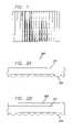
- FIG. 1is a shaded top view of a conventional lenticular screen having corduroy-like lenticules, as shown in U.S. Pat. No. 1,128,979.
- FIG. 2Ashows a cross section of lenticules coated on a glass substrate.
- FIG. 2Bshows a cross section of lenticules coated on one side of a glass substrate with an antireflective-coated surface on the opposite side of the substrate.
- FIG. 3shows the lenticular screen of FIG. 2B as it is used in juxtaposition with a flat panel display with the lenticules facing outward away from the display.
- FIG. 4shows the lenticular screen of FIG. 2B as it is used in juxtaposition with a flat panel display with the lenticules facing inward toward the display.
- FIG. 5is a schematic representation of a closed chamber formed between the lenticular screen and the flat panel display and having a pump to inject and remove a liquid from the interstices of inward-facing lenticules in order to nullify or activate, respectively, the refractive properties of the lenticules.
- FIG. 2Ashows a cross section of a lenticular screen 200 made up of lenticules 202 , which are the topmost or sector-like surfaces of long cylinders, as deposited on substrate 201 .
- lenticular screensmade to match the needs of electronic flat panel displays, we favor lenticules deposited on dimensionally stable glass; that is, on glass whose thermal expansion properties match that of the display screen so that the alignment of lenticule and pixel will remain constant.
- the substrateis some material other than glass, or if there is no substrate at all and the lenticular screen is a part of the substrate and made of one material.
- the focal length of the lenticular screen's lenticulesis the principal determinate of the angle of view of the autostereo display, and the focal length cannot be less than the thickness of the faceplate. With the lenticules facing outwards the focal length would be further increased, thereby reducing the angle of view.
- optical systemscan be reversed, and that this arrangement of parts does not spoil the reflective optical effect produced by the lenticules.
- FIG. 2Bshows a variation of the arrangement described in FIG. 2A .
- an anti-reflective (“AR”) coating 203has been applied to the surface opposite the lenticules.
- This AR coating 203may use any one of a number of well known thin film AR coating approaches relying on destructive interference of reflected rays of light.
- the glass substratecan be pre-coated, or the coating can be added after the lenticules have been applied.
- One technique at which we have become adeptis lamination of a plastic sheet of material whose outer surface is AR coated.
- FIG. 3shows us the way in which a lenticular screen 300 can be used in association with a flat panel display to obtain an autostereoscopic effect.
- the flat panel display 304(with cover-glass 305 ) faces the viewer 306 .
- a lenticular screen of the kind described in FIG. 2Ais placed in intimate juxtaposition with flat panel display 304 .
- the lenticular screenis made up of glass substrate 301 and lenticules 302 .
- FIG. 4shows the lenticules 402 , which are part of the glass substrate 401 , facing inward toward the flat panel display 404 .
- the outer face of the substrate 401is flat and it has been coated with an AR coating 403 .
- the viewer 407enjoys the autostereo image produced by the refractive properties of the screen.
- the structure of the screen itselfhas been rendered unobtrusive because the lenticular structure is facing away from the user and is in close juxtaposition with the surface of the display 404 . Additionally and importantly, AR surface 403 is directly facing the user. By this means reflections are effectively suppressed and the viewer enjoys a superior stereoscopic image.
- FIG. 5is a front view of the apparatus we are discussing as it is mounted in intimate juxtaposition with the faceplate of a flat panel display screen.
- the lenticular screen 500is of the same inward facing variety as discussed with reference to FIG. 4 above. Given that the lenticules are facing inward and towards the display screen, we have provided an area or air gap 406 between the display screen faceplate 405 and the lenticules 402 . We use this space to allow a liquid to enter or leave the air gap 406 .
- the air gap 406may be a large air gap, or it may simply consist of the interstices formed by the rounded tops of the lenticules 402 touching the faceplate 405 . These interstices form a system of channels which are parallel to the boundary between adjacent lenticules and the boundaries to form cavities or depressions in the channels.
- the chamberhas outlet ports 509 (only one such typical port shown), at the top of the display through which the air within the chamber may exit.
- the fluidis introduced through inlet ports 504 (only one such typical port is shown) at the bottom of the display, to fill the chamber.
- the chamberis fabricated in a conventional manner to prevent the fluid from becoming contaminated or leaking out.
- a manually or electrically operated mechanismsuch as a syringe, is used to contain the fluid and move it in to and out of the lenticular viewing field as desired by the user, or as automatically commanded by electronic means to be described below.
- the entire outer edge 503is sealed to keep the liquid from escaping and thereby forms chamber 502 .
- ports 504fitted to the lower edge at the bottom of the display are ports 504 , by which means the fluid is brought into the chamber.
- an additional elongated expansion chamber 505that accepts the air that is being displaced from the chamber 502 by the incoming fluid.
- the upper expansion chamber 505must be large enough to house the displaced air without building pressure that would damage the seals or other system components.
- the fluid and lenticular surface and faceplate materialare chosen or prepared so that there is a minimum “wetting” of the lenticular surface by the fluid.
- Thiscan be as simple as choosing a proper liquid or material with which to fabricate the lenticular screen, or one can also use a clear coating on the lenticular surface to achieve the same results.
- the surface of the display screenis likewise treated with the same type of coating so it may also not be “wetted” by the fluid. This will insure a complete removal of the fluid upon release of the pressure that kept it in place interstitially.
- Such coatingsare commercially available and some are of the fluoropolymer type.
- the fluidshown as hatched area 506 , partially filling the interstitial area, the optical or refractive effects of the lenticules becomes nullified and information formatted for planar viewing may be viewed.
- stereo viewingis facilitated.
- To promote removal of the fluidwe prefer to have a fluid that has a high amount of surface tension. This allows the fluid to remain as a whole entity instead of separating into small droplets within the chamber.
- Moving the fluid in to and out of the chamberis preferably achieved by means of a large syringe 507 fitted into the bottom of the display bezel.
- the fluidmay be stored and transferred by many well known conventional methods, such as the use of a bladder and pump (not shown).
- Such devicescan be activated manually, for example using handle 508 , or electrically, for example by an electromechanical mechanism, such as a motor assembly with appropriate gearing.
- an electromechanical mechanismsuch as a motor assembly with appropriate gearing.
- inventive systemwill also work for the more traditional outward facing lenticules if a cover-glass is mounted in close proximity to the lenticular screen thus forming the outer surface of the display.
- the mechanism for pumping the fluid in and out of the interstitial chamberis identical to that which has already been described, as is the optical nullifying effect.
- a video effectsuch as a fade out and a fade in.
- the coupling of such a video effectmasks the transition from stereo to planar and vice versa, which although brief, will be rendered indiscernible by this means.
- an automated systemcan invoke the switch between planar and autostereo modes.
- the graphics controllerin the case of computer usage
- the mode switchIn the case of television there are similar means to automatically activate the mode switch.
- One mechanismis to use a small portion of the visible image area to embed a unique sequence of particular RGB data values along a line, say the top or bottom line of the screen.
- the length of the sequencecan be dozens or even hundreds of pixels. In such a case, the chance of creating or perceiving a false trigger is virtually zero.
- This triggeris in the form of either a mode switch command or a mode status command.
- Such a systemis described in U.S. Pat. No. 5,572,250 to Lipton et al.
- a unique sequenceidentifies an image as an autostereo image.
- the displaythen switches to the autostereo mode as long as that sequence remains embedded in the image, or possibly as a signal within the vertical or horizontal blanking areas.
- DDCData Display Channel
- VESAData Display Channel
- This channelnormally allows the monitor to identify itself and its capabilities and to communicate that information to the graphics controller.
- the graphics controllerresponds by selecting display modes and resolutions that are appropriate.
- An additional capability of the DDCis an I 2 C bus link. The display mode can thus be controlled via the 12 C bus.
- Other mechanismsinclude any general purpose peripheral bus such as the ADB or USB; a dedicated connection via a serial or parallel port; or a “dongle” attached to an existing port such as is commonly used to read and write memory cards via a parallel printer port.
Landscapes
- Physics & Mathematics (AREA)
- Engineering & Computer Science (AREA)
- Multimedia (AREA)
- Signal Processing (AREA)
- General Physics & Mathematics (AREA)
- Optics & Photonics (AREA)
- Testing, Inspecting, Measuring Of Stereoscopic Televisions And Televisions (AREA)
Abstract
Description
Claims (17)
Priority Applications (1)
| Application Number | Priority Date | Filing Date | Title |
|---|---|---|---|
| US09/943,890US7099080B2 (en) | 2000-08-30 | 2001-08-30 | Autostereoscopic lenticular screen |
Applications Claiming Priority (2)
| Application Number | Priority Date | Filing Date | Title |
|---|---|---|---|
| US22918800P | 2000-08-30 | 2000-08-30 | |
| US09/943,890US7099080B2 (en) | 2000-08-30 | 2001-08-30 | Autostereoscopic lenticular screen |
Publications (2)
| Publication Number | Publication Date |
|---|---|
| US20020036825A1 US20020036825A1 (en) | 2002-03-28 |
| US7099080B2true US7099080B2 (en) | 2006-08-29 |
Family
ID=26923032
Family Applications (1)
| Application Number | Title | Priority Date | Filing Date |
|---|---|---|---|
| US09/943,890Expired - Fee RelatedUS7099080B2 (en) | 2000-08-30 | 2001-08-30 | Autostereoscopic lenticular screen |
Country Status (1)
| Country | Link |
|---|---|
| US (1) | US7099080B2 (en) |
Cited By (56)
| Publication number | Priority date | Publication date | Assignee | Title |
|---|---|---|---|---|
| US20050190258A1 (en)* | 1999-01-21 | 2005-09-01 | Mel Siegel | 3-D imaging arrangements |
| US20070008620A1 (en)* | 2005-07-11 | 2007-01-11 | Samsung Electronics Co., Ltd. | Switchable autostereoscopic display |
| US20080218433A1 (en)* | 2007-03-07 | 2008-09-11 | Hyung Ki Hong | Optical sheet for three-dimensional image and three-dimensional image display device using the same |
| US20080225373A1 (en)* | 2007-03-15 | 2008-09-18 | Seiko Epson Corporation | Image display apparatus and optical member therefor |
| US20090225154A1 (en)* | 2008-03-04 | 2009-09-10 | Genie Lens Technologies, Llc | 3d display system using a lenticular lens array variably spaced apart from a display screen |
| US20090295909A1 (en)* | 2005-07-04 | 2009-12-03 | Xavier Levecq | Device and Method for 2D-3D Switchable Autostereoscopic Viewing |
| US20100259819A1 (en)* | 2007-10-02 | 2010-10-14 | Koninklijke Philips Electronics N.V. | Auto-stereoscopic display device |
| US20120134019A1 (en)* | 2010-11-26 | 2012-05-31 | Boe Technology Group Co., Ltd. | Three dimension display device |
| US8786687B1 (en) | 2010-11-22 | 2014-07-22 | Lockheed Martin Corporation | Auto-stereoscopic display with lenticules and elongated light filters |
| US10089516B2 (en) | 2013-07-31 | 2018-10-02 | Digilens, Inc. | Method and apparatus for contact image sensing |
| US10145533B2 (en) | 2005-11-11 | 2018-12-04 | Digilens, Inc. | Compact holographic illumination device |
| US10156681B2 (en) | 2015-02-12 | 2018-12-18 | Digilens Inc. | Waveguide grating device |
| US10185154B2 (en) | 2011-04-07 | 2019-01-22 | Digilens, Inc. | Laser despeckler based on angular diversity |
| US10209517B2 (en) | 2013-05-20 | 2019-02-19 | Digilens, Inc. | Holographic waveguide eye tracker |
| US10216061B2 (en) | 2012-01-06 | 2019-02-26 | Digilens, Inc. | Contact image sensor using switchable bragg gratings |
| US10234696B2 (en) | 2007-07-26 | 2019-03-19 | Digilens, Inc. | Optical apparatus for recording a holographic device and method of recording |
| US10241330B2 (en) | 2014-09-19 | 2019-03-26 | Digilens, Inc. | Method and apparatus for generating input images for holographic waveguide displays |
| US10330777B2 (en) | 2015-01-20 | 2019-06-25 | Digilens Inc. | Holographic waveguide lidar |
| US10359736B2 (en) | 2014-08-08 | 2019-07-23 | Digilens Inc. | Method for holographic mastering and replication |
| US10423222B2 (en) | 2014-09-26 | 2019-09-24 | Digilens Inc. | Holographic waveguide optical tracker |
| US10437051B2 (en) | 2012-05-11 | 2019-10-08 | Digilens Inc. | Apparatus for eye tracking |
| US10437064B2 (en) | 2015-01-12 | 2019-10-08 | Digilens Inc. | Environmentally isolated waveguide display |
| US10459145B2 (en) | 2015-03-16 | 2019-10-29 | Digilens Inc. | Waveguide device incorporating a light pipe |
| US10545346B2 (en) | 2017-01-05 | 2020-01-28 | Digilens Inc. | Wearable heads up displays |
| US10591756B2 (en) | 2015-03-31 | 2020-03-17 | Digilens Inc. | Method and apparatus for contact image sensing |
| US10642058B2 (en) | 2011-08-24 | 2020-05-05 | Digilens Inc. | Wearable data display |
| US10670876B2 (en) | 2011-08-24 | 2020-06-02 | Digilens Inc. | Waveguide laser illuminator incorporating a despeckler |
| US10678053B2 (en) | 2009-04-27 | 2020-06-09 | Digilens Inc. | Diffractive projection apparatus |
| US10690916B2 (en) | 2015-10-05 | 2020-06-23 | Digilens Inc. | Apparatus for providing waveguide displays with two-dimensional pupil expansion |
| US10690851B2 (en) | 2018-03-16 | 2020-06-23 | Digilens Inc. | Holographic waveguides incorporating birefringence control and methods for their fabrication |
| US10732569B2 (en) | 2018-01-08 | 2020-08-04 | Digilens Inc. | Systems and methods for high-throughput recording of holographic gratings in waveguide cells |
| US10859768B2 (en) | 2016-03-24 | 2020-12-08 | Digilens Inc. | Method and apparatus for providing a polarization selective holographic waveguide device |
| US10890707B2 (en) | 2016-04-11 | 2021-01-12 | Digilens Inc. | Holographic waveguide apparatus for structured light projection |
| US10914950B2 (en) | 2018-01-08 | 2021-02-09 | Digilens Inc. | Waveguide architectures and related methods of manufacturing |
| US10942430B2 (en) | 2017-10-16 | 2021-03-09 | Digilens Inc. | Systems and methods for multiplying the image resolution of a pixelated display |
| US10983340B2 (en) | 2016-02-04 | 2021-04-20 | Digilens Inc. | Holographic waveguide optical tracker |
| US11307432B2 (en) | 2014-08-08 | 2022-04-19 | Digilens Inc. | Waveguide laser illuminator incorporating a Despeckler |
| US11378732B2 (en) | 2019-03-12 | 2022-07-05 | DigLens Inc. | Holographic waveguide backlight and related methods of manufacturing |
| US11402801B2 (en) | 2018-07-25 | 2022-08-02 | Digilens Inc. | Systems and methods for fabricating a multilayer optical structure |
| US11442222B2 (en) | 2019-08-29 | 2022-09-13 | Digilens Inc. | Evacuated gratings and methods of manufacturing |
| US11448937B2 (en) | 2012-11-16 | 2022-09-20 | Digilens Inc. | Transparent waveguide display for tiling a display having plural optical powers using overlapping and offset FOV tiles |
| US11460621B2 (en) | 2012-04-25 | 2022-10-04 | Rockwell Collins, Inc. | Holographic wide angle display |
| US11480788B2 (en) | 2015-01-12 | 2022-10-25 | Digilens Inc. | Light field displays incorporating holographic waveguides |
| US11513350B2 (en) | 2016-12-02 | 2022-11-29 | Digilens Inc. | Waveguide device with uniform output illumination |
| US11543594B2 (en) | 2019-02-15 | 2023-01-03 | Digilens Inc. | Methods and apparatuses for providing a holographic waveguide display using integrated gratings |
| US11681143B2 (en) | 2019-07-29 | 2023-06-20 | Digilens Inc. | Methods and apparatus for multiplying the image resolution and field-of-view of a pixelated display |
| US11726332B2 (en) | 2009-04-27 | 2023-08-15 | Digilens Inc. | Diffractive projection apparatus |
| US11747568B2 (en) | 2019-06-07 | 2023-09-05 | Digilens Inc. | Waveguides incorporating transmissive and reflective gratings and related methods of manufacturing |
| US12092914B2 (en) | 2018-01-08 | 2024-09-17 | Digilens Inc. | Systems and methods for manufacturing waveguide cells |
| US12140764B2 (en) | 2019-02-15 | 2024-11-12 | Digilens Inc. | Wide angle waveguide display |
| US12158612B2 (en) | 2021-03-05 | 2024-12-03 | Digilens Inc. | Evacuated periodic structures and methods of manufacturing |
| US12210153B2 (en) | 2019-01-14 | 2025-01-28 | Digilens Inc. | Holographic waveguide display with light control layer |
| US12222499B2 (en) | 2020-12-21 | 2025-02-11 | Digilens Inc. | Eye glow suppression in waveguide based displays |
| US12306585B2 (en) | 2018-01-08 | 2025-05-20 | Digilens Inc. | Methods for fabricating optical waveguides |
| US12399326B2 (en) | 2021-01-07 | 2025-08-26 | Digilens Inc. | Grating structures for color waveguides |
| US12397477B2 (en) | 2019-02-05 | 2025-08-26 | Digilens Inc. | Methods for compensating for optical surface nonuniformity |
Families Citing this family (29)
| Publication number | Priority date | Publication date | Assignee | Title |
|---|---|---|---|---|
| KR101166245B1 (en)* | 2001-10-11 | 2012-07-18 | 코닌클리케 필립스 일렉트로닉스 엔.브이. | 2d/3d display apparatus |
| US7841944B2 (en) | 2002-08-06 | 2010-11-30 | Igt | Gaming device having a three dimensional display device |
| US7857700B2 (en)* | 2003-09-12 | 2010-12-28 | Igt | Three-dimensional autostereoscopic image display for a gaming apparatus |
| US7616228B2 (en)* | 2003-10-02 | 2009-11-10 | Real D | Hardware based interdigitation |
| US7616227B2 (en)* | 2003-10-02 | 2009-11-10 | Real D | Hardware based interdigitation |
| KR20060134153A (en)* | 2004-04-13 | 2006-12-27 | 코닌클리케 필립스 일렉트로닉스 엔.브이. | Autostereoscopic Display Device |
| DE102005006044A1 (en)* | 2005-02-08 | 2006-08-10 | X3D Technologies Gmbh | Three dimensional display device, has transparent panel for reducing unwanted light reflections, arranged in front of filter array in front of image reproducing device |
| AU2005279331A1 (en)* | 2004-08-31 | 2006-03-09 | X3D Technologies Gmbh | Assembly for representing images in three dimensions |
| DE102004042498A1 (en)* | 2004-08-31 | 2006-03-02 | X3D Technologies Gmbh | Three-dimensional image display system has filter elements transparent to different wavelengths of visible light and has semireflecting mirror in front of filter elements |
| DE102004044802A1 (en)* | 2004-09-13 | 2006-03-30 | X3D Technologies Gmbh | Arrangement for optionally three-dimensionally perceptible or two-dimensional representation of images |
| US7878910B2 (en)* | 2005-09-13 | 2011-02-01 | Igt | Gaming machine with scanning 3-D display system |
| US7652674B2 (en) | 2006-02-09 | 2010-01-26 | Real D | On the fly hardware based interdigitation |
| WO2008075270A2 (en)* | 2006-12-19 | 2008-06-26 | Koninklijke Philips Electronics N.V. | A lens structure and manufacturing method, and the manufacture of shaped polymer articles |
| US20100033813A1 (en)* | 2008-08-05 | 2010-02-11 | Rogoff Gerald L | 3-D Display Requiring No Special Eyewear |
| US8175398B2 (en)* | 2008-11-10 | 2012-05-08 | City University Of Hong Kong | Method for encoding a plurality of video signals into a single video signal |
| US20110199469A1 (en)* | 2010-02-15 | 2011-08-18 | Gallagher Andrew C | Detection and display of stereo images |
| US20110199463A1 (en)* | 2010-02-15 | 2011-08-18 | Gallagher Andrew C | Display with integrated camera |
| US8384774B2 (en) | 2010-02-15 | 2013-02-26 | Eastman Kodak Company | Glasses for viewing stereo images |
| US20110199468A1 (en)* | 2010-02-15 | 2011-08-18 | Gallagher Andrew C | 3-dimensional display with preferences |
| US20120236133A1 (en) | 2011-03-18 | 2012-09-20 | Andrew Charles Gallagher | Producing enhanced images from anaglyph images |
| US9041771B2 (en) | 2011-06-08 | 2015-05-26 | City University Of Hong Kong | Automatic switching of a multi-mode display for displaying three-dimensional and two-dimensional images |
| KR101818253B1 (en)* | 2011-10-21 | 2018-01-15 | 엘지디스플레이 주식회사 | Stereoscopic Image Display Device |
| US9280042B2 (en)* | 2012-03-16 | 2016-03-08 | City University Of Hong Kong | Automatic switching of a multi-mode projector display screen for displaying three-dimensional and two-dimensional images |
| CN103728678B (en)* | 2013-12-26 | 2015-04-22 | 京东方科技集团股份有限公司 | Cylindrical lens assembly and display device |
| CN103913847B (en)* | 2014-03-19 | 2015-12-02 | 京东方科技集团股份有限公司 | A kind of three-dimensional display system |
| US10445972B2 (en)* | 2014-10-10 | 2019-10-15 | Team Play, Inc. | Amusement game machine and method of play having a transmissive electronic display panel overlying play field |
| CN105093544B (en)* | 2015-08-12 | 2017-06-30 | 京东方科技集团股份有限公司 | Display device |
| CN115685407A (en)* | 2021-07-26 | 2023-02-03 | 京东方科技集团股份有限公司 | Display panel and display device |
| CN115379090A (en)* | 2022-08-03 | 2022-11-22 | 奕目(上海)科技有限公司 | Imaging device |
Citations (8)
| Publication number | Priority date | Publication date | Assignee | Title |
|---|---|---|---|---|
| US1128979A (en) | 1912-06-01 | 1915-02-16 | Walter Hess | Stereoscopic picture. |
| US3600063A (en)* | 1969-04-28 | 1971-08-17 | Thomas R Bowen | Varifocal beam spreader |
| US5500765A (en) | 1994-05-11 | 1996-03-19 | Dimension Technologies Inc. | Convertible 2D/3D autostereoscopic display |
| US5572250A (en) | 1994-10-20 | 1996-11-05 | Stereographics Corporation | Universal electronic stereoscopic display |
| US6046855A (en)* | 1997-10-22 | 2000-04-04 | Dai Nippon Printing Co., Ltd. | Lenticular lens sheet and process for producing the same |
| US6069650A (en)* | 1996-11-14 | 2000-05-30 | U.S. Philips Corporation | Autostereoscopic display apparatus |
| US6288846B1 (en)* | 1999-09-24 | 2001-09-11 | Arizona Carbon Foil Co., Inc. | Variable focal-length lens assembly |
| US6481849B2 (en)* | 1997-03-27 | 2002-11-19 | .Litton Systems, Inc. | Autostereo projection system |
- 2001
- 2001-08-30USUS09/943,890patent/US7099080B2/ennot_activeExpired - Fee Related
Patent Citations (8)
| Publication number | Priority date | Publication date | Assignee | Title |
|---|---|---|---|---|
| US1128979A (en) | 1912-06-01 | 1915-02-16 | Walter Hess | Stereoscopic picture. |
| US3600063A (en)* | 1969-04-28 | 1971-08-17 | Thomas R Bowen | Varifocal beam spreader |
| US5500765A (en) | 1994-05-11 | 1996-03-19 | Dimension Technologies Inc. | Convertible 2D/3D autostereoscopic display |
| US5572250A (en) | 1994-10-20 | 1996-11-05 | Stereographics Corporation | Universal electronic stereoscopic display |
| US6069650A (en)* | 1996-11-14 | 2000-05-30 | U.S. Philips Corporation | Autostereoscopic display apparatus |
| US6481849B2 (en)* | 1997-03-27 | 2002-11-19 | .Litton Systems, Inc. | Autostereo projection system |
| US6046855A (en)* | 1997-10-22 | 2000-04-04 | Dai Nippon Printing Co., Ltd. | Lenticular lens sheet and process for producing the same |
| US6288846B1 (en)* | 1999-09-24 | 2001-09-11 | Arizona Carbon Foil Co., Inc. | Variable focal-length lens assembly |
Cited By (97)
| Publication number | Priority date | Publication date | Assignee | Title |
|---|---|---|---|---|
| US20050190258A1 (en)* | 1999-01-21 | 2005-09-01 | Mel Siegel | 3-D imaging arrangements |
| US7440004B2 (en)* | 1999-01-21 | 2008-10-21 | Mel Siegel | 3-D imaging arrangements |
| US20090295909A1 (en)* | 2005-07-04 | 2009-12-03 | Xavier Levecq | Device and Method for 2D-3D Switchable Autostereoscopic Viewing |
| US20070008620A1 (en)* | 2005-07-11 | 2007-01-11 | Samsung Electronics Co., Ltd. | Switchable autostereoscopic display |
| US10145533B2 (en) | 2005-11-11 | 2018-12-04 | Digilens, Inc. | Compact holographic illumination device |
| US8339705B2 (en)* | 2007-03-07 | 2012-12-25 | Lg Display Co., Ltd. | Optical sheet for three-dimensional image and three-dimensional image display device using the same |
| US20080218433A1 (en)* | 2007-03-07 | 2008-09-11 | Hyung Ki Hong | Optical sheet for three-dimensional image and three-dimensional image display device using the same |
| US7630131B2 (en)* | 2007-03-15 | 2009-12-08 | Seiko Epson Corporation | Image display apparatus and optical member therefor |
| CN101266338B (en)* | 2007-03-15 | 2011-05-11 | 精工爱普生株式会社 | Image display apparatus and optical member therefor |
| US20080225373A1 (en)* | 2007-03-15 | 2008-09-18 | Seiko Epson Corporation | Image display apparatus and optical member therefor |
| US10725312B2 (en) | 2007-07-26 | 2020-07-28 | Digilens Inc. | Laser illumination device |
| US10234696B2 (en) | 2007-07-26 | 2019-03-19 | Digilens, Inc. | Optical apparatus for recording a holographic device and method of recording |
| US20100259819A1 (en)* | 2007-10-02 | 2010-10-14 | Koninklijke Philips Electronics N.V. | Auto-stereoscopic display device |
| US9807377B2 (en)* | 2007-10-02 | 2017-10-31 | Koninklijke Philips N.V. | Auto-stereoscopic display device |
| US20090225154A1 (en)* | 2008-03-04 | 2009-09-10 | Genie Lens Technologies, Llc | 3d display system using a lenticular lens array variably spaced apart from a display screen |
| US8253780B2 (en)* | 2008-03-04 | 2012-08-28 | Genie Lens Technology, LLC | 3D display system using a lenticular lens array variably spaced apart from a display screen |
| US11726332B2 (en) | 2009-04-27 | 2023-08-15 | Digilens Inc. | Diffractive projection apparatus |
| US11175512B2 (en) | 2009-04-27 | 2021-11-16 | Digilens Inc. | Diffractive projection apparatus |
| US10678053B2 (en) | 2009-04-27 | 2020-06-09 | Digilens Inc. | Diffractive projection apparatus |
| US8786687B1 (en) | 2010-11-22 | 2014-07-22 | Lockheed Martin Corporation | Auto-stereoscopic display with lenticules and elongated light filters |
| US20120134019A1 (en)* | 2010-11-26 | 2012-05-31 | Boe Technology Group Co., Ltd. | Three dimension display device |
| US10185154B2 (en) | 2011-04-07 | 2019-01-22 | Digilens, Inc. | Laser despeckler based on angular diversity |
| US11487131B2 (en) | 2011-04-07 | 2022-11-01 | Digilens Inc. | Laser despeckler based on angular diversity |
| US12306418B2 (en) | 2011-08-24 | 2025-05-20 | Rockwell Collins, Inc. | Wearable data display |
| US10670876B2 (en) | 2011-08-24 | 2020-06-02 | Digilens Inc. | Waveguide laser illuminator incorporating a despeckler |
| US10642058B2 (en) | 2011-08-24 | 2020-05-05 | Digilens Inc. | Wearable data display |
| US11287666B2 (en) | 2011-08-24 | 2022-03-29 | Digilens, Inc. | Wearable data display |
| US10216061B2 (en) | 2012-01-06 | 2019-02-26 | Digilens, Inc. | Contact image sensor using switchable bragg gratings |
| US10459311B2 (en) | 2012-01-06 | 2019-10-29 | Digilens Inc. | Contact image sensor using switchable Bragg gratings |
| US11460621B2 (en) | 2012-04-25 | 2022-10-04 | Rockwell Collins, Inc. | Holographic wide angle display |
| US10437051B2 (en) | 2012-05-11 | 2019-10-08 | Digilens Inc. | Apparatus for eye tracking |
| US11994674B2 (en) | 2012-05-11 | 2024-05-28 | Digilens Inc. | Apparatus for eye tracking |
| US11448937B2 (en) | 2012-11-16 | 2022-09-20 | Digilens Inc. | Transparent waveguide display for tiling a display having plural optical powers using overlapping and offset FOV tiles |
| US12405507B2 (en) | 2012-11-16 | 2025-09-02 | Digilens Inc. | Transparent waveguide display with grating lamina that both couple and extract modulated light |
| US11815781B2 (en)* | 2012-11-16 | 2023-11-14 | Rockwell Collins, Inc. | Transparent waveguide display |
| US20230114549A1 (en)* | 2012-11-16 | 2023-04-13 | Rockwell Collins, Inc. | Transparent waveguide display |
| US11662590B2 (en) | 2013-05-20 | 2023-05-30 | Digilens Inc. | Holographic waveguide eye tracker |
| US10209517B2 (en) | 2013-05-20 | 2019-02-19 | Digilens, Inc. | Holographic waveguide eye tracker |
| US10423813B2 (en) | 2013-07-31 | 2019-09-24 | Digilens Inc. | Method and apparatus for contact image sensing |
| US10089516B2 (en) | 2013-07-31 | 2018-10-02 | Digilens, Inc. | Method and apparatus for contact image sensing |
| US11709373B2 (en) | 2014-08-08 | 2023-07-25 | Digilens Inc. | Waveguide laser illuminator incorporating a despeckler |
| US10359736B2 (en) | 2014-08-08 | 2019-07-23 | Digilens Inc. | Method for holographic mastering and replication |
| US11307432B2 (en) | 2014-08-08 | 2022-04-19 | Digilens Inc. | Waveguide laser illuminator incorporating a Despeckler |
| US11726323B2 (en) | 2014-09-19 | 2023-08-15 | Digilens Inc. | Method and apparatus for generating input images for holographic waveguide displays |
| US10241330B2 (en) | 2014-09-19 | 2019-03-26 | Digilens, Inc. | Method and apparatus for generating input images for holographic waveguide displays |
| US10423222B2 (en) | 2014-09-26 | 2019-09-24 | Digilens Inc. | Holographic waveguide optical tracker |
| US11740472B2 (en) | 2015-01-12 | 2023-08-29 | Digilens Inc. | Environmentally isolated waveguide display |
| US11726329B2 (en) | 2015-01-12 | 2023-08-15 | Digilens Inc. | Environmentally isolated waveguide display |
| US10437064B2 (en) | 2015-01-12 | 2019-10-08 | Digilens Inc. | Environmentally isolated waveguide display |
| US11480788B2 (en) | 2015-01-12 | 2022-10-25 | Digilens Inc. | Light field displays incorporating holographic waveguides |
| US10330777B2 (en) | 2015-01-20 | 2019-06-25 | Digilens Inc. | Holographic waveguide lidar |
| US12379547B2 (en) | 2015-02-12 | 2025-08-05 | Digilens Inc. | Waveguide grating device |
| US11703645B2 (en) | 2015-02-12 | 2023-07-18 | Digilens Inc. | Waveguide grating device |
| US10156681B2 (en) | 2015-02-12 | 2018-12-18 | Digilens Inc. | Waveguide grating device |
| US10527797B2 (en) | 2015-02-12 | 2020-01-07 | Digilens Inc. | Waveguide grating device |
| US10459145B2 (en) | 2015-03-16 | 2019-10-29 | Digilens Inc. | Waveguide device incorporating a light pipe |
| US12013561B2 (en) | 2015-03-16 | 2024-06-18 | Digilens Inc. | Waveguide device incorporating a light pipe |
| US10591756B2 (en) | 2015-03-31 | 2020-03-17 | Digilens Inc. | Method and apparatus for contact image sensing |
| US11281013B2 (en) | 2015-10-05 | 2022-03-22 | Digilens Inc. | Apparatus for providing waveguide displays with two-dimensional pupil expansion |
| US10690916B2 (en) | 2015-10-05 | 2020-06-23 | Digilens Inc. | Apparatus for providing waveguide displays with two-dimensional pupil expansion |
| US11754842B2 (en) | 2015-10-05 | 2023-09-12 | Digilens Inc. | Apparatus for providing waveguide displays with two-dimensional pupil expansion |
| US12405471B2 (en) | 2015-10-05 | 2025-09-02 | Digilens Inc. | Apparatus for providing waveguide displays with two-dimensional pupil expansion |
| US10983340B2 (en) | 2016-02-04 | 2021-04-20 | Digilens Inc. | Holographic waveguide optical tracker |
| US10859768B2 (en) | 2016-03-24 | 2020-12-08 | Digilens Inc. | Method and apparatus for providing a polarization selective holographic waveguide device |
| US11604314B2 (en) | 2016-03-24 | 2023-03-14 | Digilens Inc. | Method and apparatus for providing a polarization selective holographic waveguide device |
| US10890707B2 (en) | 2016-04-11 | 2021-01-12 | Digilens Inc. | Holographic waveguide apparatus for structured light projection |
| US11513350B2 (en) | 2016-12-02 | 2022-11-29 | Digilens Inc. | Waveguide device with uniform output illumination |
| US12298513B2 (en) | 2016-12-02 | 2025-05-13 | Digilens Inc. | Waveguide device with uniform output illumination |
| US10545346B2 (en) | 2017-01-05 | 2020-01-28 | Digilens Inc. | Wearable heads up displays |
| US11586046B2 (en) | 2017-01-05 | 2023-02-21 | Digilens Inc. | Wearable heads up displays |
| US11194162B2 (en) | 2017-01-05 | 2021-12-07 | Digilens Inc. | Wearable heads up displays |
| US12248150B2 (en) | 2017-01-05 | 2025-03-11 | Digilens Inc. | Wearable heads up displays |
| US10942430B2 (en) | 2017-10-16 | 2021-03-09 | Digilens Inc. | Systems and methods for multiplying the image resolution of a pixelated display |
| US12352960B2 (en) | 2018-01-08 | 2025-07-08 | Digilens Inc. | Waveguide architectures and related methods of manufacturing |
| US12306585B2 (en) | 2018-01-08 | 2025-05-20 | Digilens Inc. | Methods for fabricating optical waveguides |
| US12366823B2 (en) | 2018-01-08 | 2025-07-22 | Digilens Inc. | Systems and methods for high-throughput recording of holographic gratings in waveguide cells |
| US10732569B2 (en) | 2018-01-08 | 2020-08-04 | Digilens Inc. | Systems and methods for high-throughput recording of holographic gratings in waveguide cells |
| US12092914B2 (en) | 2018-01-08 | 2024-09-17 | Digilens Inc. | Systems and methods for manufacturing waveguide cells |
| US10914950B2 (en) | 2018-01-08 | 2021-02-09 | Digilens Inc. | Waveguide architectures and related methods of manufacturing |
| US10690851B2 (en) | 2018-03-16 | 2020-06-23 | Digilens Inc. | Holographic waveguides incorporating birefringence control and methods for their fabrication |
| US11726261B2 (en) | 2018-03-16 | 2023-08-15 | Digilens Inc. | Holographic waveguides incorporating birefringence control and methods for their fabrication |
| US11150408B2 (en) | 2018-03-16 | 2021-10-19 | Digilens Inc. | Holographic waveguides incorporating birefringence control and methods for their fabrication |
| US11402801B2 (en) | 2018-07-25 | 2022-08-02 | Digilens Inc. | Systems and methods for fabricating a multilayer optical structure |
| US12210153B2 (en) | 2019-01-14 | 2025-01-28 | Digilens Inc. | Holographic waveguide display with light control layer |
| US12397477B2 (en) | 2019-02-05 | 2025-08-26 | Digilens Inc. | Methods for compensating for optical surface nonuniformity |
| US12140764B2 (en) | 2019-02-15 | 2024-11-12 | Digilens Inc. | Wide angle waveguide display |
| US11543594B2 (en) | 2019-02-15 | 2023-01-03 | Digilens Inc. | Methods and apparatuses for providing a holographic waveguide display using integrated gratings |
| US11378732B2 (en) | 2019-03-12 | 2022-07-05 | DigLens Inc. | Holographic waveguide backlight and related methods of manufacturing |
| US12271035B2 (en) | 2019-06-07 | 2025-04-08 | Digilens Inc. | Waveguides incorporating transmissive and reflective gratings and related methods of manufacturing |
| US11747568B2 (en) | 2019-06-07 | 2023-09-05 | Digilens Inc. | Waveguides incorporating transmissive and reflective gratings and related methods of manufacturing |
| US11681143B2 (en) | 2019-07-29 | 2023-06-20 | Digilens Inc. | Methods and apparatus for multiplying the image resolution and field-of-view of a pixelated display |
| US11442222B2 (en) | 2019-08-29 | 2022-09-13 | Digilens Inc. | Evacuated gratings and methods of manufacturing |
| US11592614B2 (en) | 2019-08-29 | 2023-02-28 | Digilens Inc. | Evacuated gratings and methods of manufacturing |
| US11899238B2 (en) | 2019-08-29 | 2024-02-13 | Digilens Inc. | Evacuated gratings and methods of manufacturing |
| US12222499B2 (en) | 2020-12-21 | 2025-02-11 | Digilens Inc. | Eye glow suppression in waveguide based displays |
| US12399326B2 (en) | 2021-01-07 | 2025-08-26 | Digilens Inc. | Grating structures for color waveguides |
| US12158612B2 (en) | 2021-03-05 | 2024-12-03 | Digilens Inc. | Evacuated periodic structures and methods of manufacturing |
Also Published As
| Publication number | Publication date |
|---|---|
| US20020036825A1 (en) | 2002-03-28 |
Similar Documents
| Publication | Publication Date | Title |
|---|---|---|
| US7099080B2 (en) | Autostereoscopic lenticular screen | |
| EP1057070B1 (en) | A multi-layer display and a method for displaying images on such a display | |
| US10429659B2 (en) | Optical arrangement and an autostereoscopic display device incorporating the same | |
| JP5576762B2 (en) | Display control device | |
| US8976323B2 (en) | Switching dual layer display with independent layer content and a dynamic mask | |
| CN101278566B (en) | Improvements to lens structures employing light blocking features | |
| US7408696B2 (en) | Three-dimensional electrophoretic displays | |
| JP3411281B2 (en) | 3D image display method and apparatus | |
| US20130278872A1 (en) | Seamless display panel using fiber optic carpet | |
| US20050286133A1 (en) | Autostereoscopic lens sheet with planar areas | |
| US20080043092A1 (en) | Multiple View Display | |
| US20030048522A1 (en) | Three-dimensional electrophoretic displays | |
| US7697208B2 (en) | 3D display with an improved pixel structure (pixelsplitting) | |
| WO2015198606A1 (en) | Image data redundancy for high quality 3D | |
| US20060192908A1 (en) | Arrangement for two-or three-dimensional display | |
| CN101419303B (en) | Color filter substrate, manufacturing method thereof and liquid crystal display panel | |
| US20180348533A1 (en) | Display system and display method of display system | |
| Boev et al. | Comparative study of autostereoscopic displays for mobile devices | |
| CN111771153A (en) | Near-eye display device and method of displaying three-dimensional image | |
| WO2025050065A1 (en) | Augmented superstereoscopic display | |
| Uehara et al. | 1-inch diagonal transflective 2D and 3D LCD with HDDP arrangement | |
| AU2004278801A1 (en) | Auto-stereo three-dimensional images | |
| US10178376B2 (en) | Hybrid transparent auto stereoscopic display | |
| KR101290839B1 (en) | Autostereoscopic lens sheet with planar areas |
Legal Events
| Date | Code | Title | Description |
|---|---|---|---|
| AS | Assignment | Owner name:STEREOGRAPHICS CORPORATION, CALIFORNIA Free format text:ASSIGNMENT OF ASSIGNORS INTEREST;ASSIGNORS:LIPTON, LENNY;MCKEE, WILLIAM;HALNON, JEFFREY JAMES;REEL/FRAME:012313/0805 Effective date:20011108 | |
| AS | Assignment | Owner name:STEREOGRAPHICS ENTERTAINMENT, INC., CALIFORNIA Free format text:ASSIGNMENT OF ASSIGNORS INTEREST;ASSIGNOR:STEREOGRAPHICS CORPORATION;REEL/FRAME:015732/0750 Effective date:20050211 Owner name:STEREOGRAPHICS ENTERTAINMENT, INC.,CALIFORNIA Free format text:ASSIGNMENT OF ASSIGNORS INTEREST;ASSIGNOR:STEREOGRAPHICS CORPORATION;REEL/FRAME:015732/0750 Effective date:20050211 | |
| AS | Assignment | Owner name:STEREOGRAPHICS CORPORATION, CALIFORNIA Free format text:CHANGE OF NAME;ASSIGNOR:STEREOGRAPHICS ENTERTAINMENT, INC.;REEL/FRAME:015778/0443 Effective date:20050207 Owner name:STEREOGRAPHICS CORPORATION,CALIFORNIA Free format text:CHANGE OF NAME;ASSIGNOR:STEREOGRAPHICS ENTERTAINMENT, INC.;REEL/FRAME:015778/0443 Effective date:20050207 | |
| AS | Assignment | Owner name:HOBBIT INVESTMENTS, LLC, COLORADO Free format text:SECURITY AGREEMENT;ASSIGNOR:STEREOGRAPHICS CORPORATION;REEL/FRAME:015778/0592 Effective date:20050211 Owner name:HOBBIT INVESTMENTS, LLC,COLORADO Free format text:SECURITY AGREEMENT;ASSIGNOR:STEREOGRAPHICS CORPORATION;REEL/FRAME:015778/0592 Effective date:20050211 | |
| AS | Assignment | Owner name:STG RESIDUAL, INC. (FORMERLY STEREOGRAPHICS CORPOR Free format text:SECURITY AGREEMENT;ASSIGNOR:STEREOGRAPHICS CORPORATION (FORMERLY STEREOGRAPHICS ENTERTAINMENT, INC.);REEL/FRAME:015797/0758 Effective date:20050211 | |
| AS | Assignment | Owner name:LEDOR, LLC,FLORIDA Free format text:ASSIGNMENT OF ASSIGNORS INTEREST;ASSIGNOR:STEREOGRAPHICS CORPORATION;REEL/FRAME:016226/0468 Effective date:20050630 Owner name:LEDOR, LLC, FLORIDA Free format text:ASSIGNMENT OF ASSIGNORS INTEREST;ASSIGNOR:STEREOGRAPHICS CORPORATION;REEL/FRAME:016226/0468 Effective date:20050630 | |
| AS | Assignment | Owner name:REDEBT, LLC,CALIFORNIA Free format text:ASSIGNMENT OF ASSIGNORS INTEREST;ASSIGNOR:STEREOGRAPHICS CORPORATION;REEL/FRAME:017575/0604 Effective date:20060322 Owner name:REDEBT, LLC, CALIFORNIA Free format text:ASSIGNMENT OF ASSIGNORS INTEREST;ASSIGNOR:STEREOGRAPHICS CORPORATION;REEL/FRAME:017575/0604 Effective date:20060322 | |
| AS | Assignment | Owner name:STEREOGRAPHICS CORPORATION,CALIFORNIA Free format text:UCC-3 - DISCHARGE OF SECURITY INTEREST;ASSIGNOR:REDEBT, LLC;REEL/FRAME:019246/0149 Effective date:20070327 Owner name:STEREOGRAPHICS CORPORATION, CALIFORNIA Free format text:UCC-3 - DISCHARGE OF SECURITY INTEREST;ASSIGNOR:REDEBT, LLC;REEL/FRAME:019246/0149 Effective date:20070327 | |
| AS | Assignment | Owner name:REAL D, CALIFORNIA Free format text:ASSIGNMENT OF ASSIGNORS INTEREST;ASSIGNORS:STEREOGRAPHICS CORPORATION;STEREOGRAPHICS ENTERTAINMENT, INC.;REEL/FRAME:020963/0354 Effective date:20080515 Owner name:REAL D,CALIFORNIA Free format text:ASSIGNMENT OF ASSIGNORS INTEREST;ASSIGNORS:STEREOGRAPHICS CORPORATION;STEREOGRAPHICS ENTERTAINMENT, INC.;REEL/FRAME:020963/0354 Effective date:20080515 | |
| AS | Assignment | Owner name:REAL D, CALIFORNIA Free format text:RELEASE OF PATENT AND TRADEMARK SECURITY AGREEMENT;ASSIGNORS:STG RESIDUAL, INC. FORMERLY KNOWN AS STEREOGRAPHICS CORPORATION;STEREOGRAPHICS CORPORATION FORMERLY KNOWN AS STEREOGRAPHICS ENTERTAINMENT, INC.;REEL/FRAME:021076/0681 Effective date:20080611 Owner name:REAL D,CALIFORNIA Free format text:RELEASE OF PATENT AND TRADEMARK SECURITY AGREEMENT;ASSIGNORS:STG RESIDUAL, INC. FORMERLY KNOWN AS STEREOGRAPHICS CORPORATION;STEREOGRAPHICS CORPORATION FORMERLY KNOWN AS STEREOGRAPHICS ENTERTAINMENT, INC.;REEL/FRAME:021076/0681 Effective date:20080611 | |
| AS | Assignment | Owner name:STEREOGRAPHICS CORPORATION, CALIFORNIA Free format text:RELEASE OF COLLATERAL ASSIGNMENT AND SECURITY INTEREST OF PATENT AND TRADEMARK RIGHTS;ASSIGNOR:HOBBITT INVESTMENTS, LLC;REEL/FRAME:021316/0369 Effective date:20080602 Owner name:STEREOGRAPHICS CORPORATION,CALIFORNIA Free format text:RELEASE OF COLLATERAL ASSIGNMENT AND SECURITY INTEREST OF PATENT AND TRADEMARK RIGHTS;ASSIGNOR:HOBBITT INVESTMENTS, LLC;REEL/FRAME:021316/0369 Effective date:20080602 | |
| FPAY | Fee payment | Year of fee payment:4 | |
| AS | Assignment | Owner name:STEREOGRAPHICS CORPORATION,CALIFORNIA Free format text:RELEASE BY SECURED PARTY;ASSIGNOR:LEDOR, LLC;REEL/FRAME:024286/0022 Effective date:20100423 Owner name:STEREOGRAPHICS CORPORATION, CALIFORNIA Free format text:RELEASE BY SECURED PARTY;ASSIGNOR:LEDOR, LLC;REEL/FRAME:024286/0022 Effective date:20100423 | |
| AS | Assignment | Owner name:REALD INC.,CALIFORNIA Free format text:MERGER;ASSIGNOR:REAL D;REEL/FRAME:024294/0658 Effective date:20100408 Owner name:REALD INC., CALIFORNIA Free format text:MERGER;ASSIGNOR:REAL D;REEL/FRAME:024294/0658 Effective date:20100408 | |
| FPAY | Fee payment | Year of fee payment:8 | |
| FEPP | Fee payment procedure | Free format text:MAINTENANCE FEE REMINDER MAILED (ORIGINAL EVENT CODE: REM.) | |
| LAPS | Lapse for failure to pay maintenance fees | Free format text:PATENT EXPIRED FOR FAILURE TO PAY MAINTENANCE FEES (ORIGINAL EVENT CODE: EXP.); ENTITY STATUS OF PATENT OWNER: SMALL ENTITY | |
| STCH | Information on status: patent discontinuation | Free format text:PATENT EXPIRED DUE TO NONPAYMENT OF MAINTENANCE FEES UNDER 37 CFR 1.362 | |
| FP | Lapsed due to failure to pay maintenance fee | Effective date:20180829 |