US7098773B2 - Power line communication system and method of operating the same - Google Patents
Power line communication system and method of operating the sameDownload PDFInfo
- Publication number
- US7098773B2 US7098773B2US10/884,685US88468504AUS7098773B2US 7098773 B2US7098773 B2US 7098773B2US 88468504 AUS88468504 AUS 88468504AUS 7098773 B2US7098773 B2US 7098773B2
- Authority
- US
- United States
- Prior art keywords
- power line
- communications
- communication
- medium
- data
- Prior art date
- Legal status (The legal status is an assumption and is not a legal conclusion. Google has not performed a legal analysis and makes no representation as to the accuracy of the status listed.)
- Expired - Fee Related, expires
Links
- 230000006854communicationEffects0.000titleclaimsabstractdescription231
- 238000004891communicationMethods0.000titleclaimsabstractdescription231
- 238000000034methodMethods0.000titleclaimsdescription27
- 238000009826distributionMethods0.000claimsdescription46
- 230000005540biological transmissionEffects0.000claimsdescription16
- 239000000835fiberSubstances0.000claimsdescription12
- 230000008878couplingEffects0.000claimsdescription11
- 238000010168coupling processMethods0.000claimsdescription11
- 238000005859coupling reactionMethods0.000claimsdescription11
- 238000011144upstream manufacturingMethods0.000abstractdescription34
- 239000004020conductorSubstances0.000description59
- 230000006870functionEffects0.000description12
- 238000001914filtrationMethods0.000description9
- 238000012545processingMethods0.000description9
- 238000010586diagramMethods0.000description7
- 230000007935neutral effectEffects0.000description7
- 238000013519translationMethods0.000description6
- 230000008901benefitEffects0.000description5
- 230000001939inductive effectEffects0.000description5
- 238000009434installationMethods0.000description5
- 238000004804windingMethods0.000description4
- 230000002776aggregationEffects0.000description3
- 238000004220aggregationMethods0.000description3
- 239000003990capacitorSubstances0.000description3
- 239000000969carrierSubstances0.000description3
- 238000001514detection methodMethods0.000description3
- 238000002955isolationMethods0.000description3
- 238000005259measurementMethods0.000description3
- 239000013256coordination polymerSubstances0.000description2
- 238000011161developmentMethods0.000description2
- 230000018109developmental processEffects0.000description2
- 238000007726management methodMethods0.000description2
- 238000012986modificationMethods0.000description2
- 230000004048modificationEffects0.000description2
- 238000010248power generationMethods0.000description2
- 238000012913prioritisationMethods0.000description2
- 230000008569processEffects0.000description2
- 230000008929regenerationEffects0.000description2
- 238000011069regeneration methodMethods0.000description2
- 230000007704transitionEffects0.000description2
- 238000013475authorizationMethods0.000description1
- 230000007175bidirectional communicationEffects0.000description1
- 238000006243chemical reactionMethods0.000description1
- 238000012937correctionMethods0.000description1
- 230000001934delayEffects0.000description1
- 238000013461designMethods0.000description1
- 238000004519manufacturing processMethods0.000description1
- 239000000463materialSubstances0.000description1
- 230000007246mechanismEffects0.000description1
- 238000012544monitoring processMethods0.000description1
- 230000003287optical effectEffects0.000description1
- 230000010363phase shiftEffects0.000description1
- 238000001907polarising light microscopyMethods0.000description1
- 230000000135prohibitive effectEffects0.000description1
- 230000003595spectral effectEffects0.000description1
- 238000003860storageMethods0.000description1
- 230000001360synchronised effectEffects0.000description1
- 238000012546transferMethods0.000description1
- XLYOFNOQVPJJNP-UHFFFAOYSA-NwaterSubstancesOXLYOFNOQVPJJNP-UHFFFAOYSA-N0.000description1
Images


Classifications
- H—ELECTRICITY
- H04—ELECTRIC COMMUNICATION TECHNIQUE
- H04B—TRANSMISSION
- H04B3/00—Line transmission systems
- H04B3/54—Systems for transmission via power distribution lines
- H04B3/56—Circuits for coupling, blocking, or by-passing of signals
- H—ELECTRICITY
- H04—ELECTRIC COMMUNICATION TECHNIQUE
- H04B—TRANSMISSION
- H04B2203/00—Indexing scheme relating to line transmission systems
- H04B2203/54—Aspects of powerline communications not already covered by H04B3/54 and its subgroups
- H04B2203/5462—Systems for power line communications
- H04B2203/5483—Systems for power line communications using coupling circuits
Definitions
- the present inventiongenerally relates to data communications over a power distribution system and more particularly, to a system and method for communicating data, which may include video, audio, voice, and/or other data types.
- PLCSpower line communication system
- existing power linesthat already have been run to many homes and offices, can be used to carry data signals to and from the homes and offices. These data signals are communicated on and off the power lines at various points in the power line communication system, such as, for example, near homes, offices, Internet service providers, and the like.
- Power distribution systemsinclude numerous sections, which transmit power at different voltages.
- the transition from one section to anothertypically is accomplished with a transformer.
- the sections of the power distribution system that are connected to the customers premisestypically are low voltage (LV) sections having a voltage between 100 volts(V) and 240V, depending on the system. In the United States, the LV section typically is about 120V.
- the sections of the power distribution system that provide the power to the LV sectionsare referred to as the medium voltage (MV) sections.
- the voltage of the MV sectionis in the range of 1,000V to 100,000V.
- the transition from the MV section to the LV section of the power distribution systemtypically is accomplished with a distribution transformer, which converts the higher voltage of the MV section to the lower voltage of the LV section.
- Power system transformersare another obstacle to using power distribution lines for data communication.
- Transformersact as a low-pass filter, passing the low frequency signals (e.g., the 50 or 60 Hz) power signals and impeding the high frequency signals (e.g., frequencies typically used for data communication).
- the low frequency signalse.g., the 50 or 60 Hz
- the high frequency signalse.g., frequencies typically used for data communication.
- some power line communications systemsface the challenge of communicating the data signals around, or through, the distribution transformers.
- conventional communication mediasuch as coaxial cables, Ethernet cables, fiber optic cables, and twisted pair
- conventional communication mediatypically provide significantly better characteristics for communicating data than power lines.
- the cost of installing the conventional communications mediumi.e., non-power line communications medium
- a major cost of installing such mediais the segment that extends from the common communication link, which typically is along the street, to each customer premises. This segment typically requires a dedicated cable for each customer premises.
- LV power linesconstitute infrastructure that is already in place.
- a communications systemit would be advantageous for a communications system to make use of this existing infrastructure in order to save time and reduce costs of the installation.
- the LV power linesextend from each customer premises to a distribution transformer and are all electrically connected to each other remote from the premises such as near the transformer.
- the LV power lines that electrically connect one customer premises to a distribution transformerare also electrically connected to the LV power lines connected to all the other customer premises receiving power from that distribution transformer. Consequently, a communications system employing the LV power lines must be able to tolerate the interference produced by many users.
- the communications systemshould provide bus arbitration and router functions for numerous customers who share a LV subnet (i.e., the LV power lines that are all electrically connected to the LV side of the transformer).
- the present inventionprovides a power line communications system that may employ power lines and non-power communications mediums.
- the systemis comprised of a plurality of interface devices with each being in communication with one or more user devices via one or more low voltage power lines.
- Each interface devicealso may be in communication with an upstream communications device via a non-power line communications medium.
- the upstream communications devicemay communicate with a backhaul point via a backhaul link to provide access to a network such as the Internet.
- each interface deviceprovides an interface between one or more low voltage power lines and the non-power line communications medium, which may be a coaxial cable.
- the upstream communications devicemay provide routing for data communicated with the interface devices.
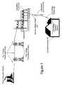
- FIG. 1is a diagram of an exemplary power distribution system with which the present invention may be employed
- FIG. 2is a diagram of a power line communications system, in accordance with an example embodiment of the present invention.
- FIG. 3is a schematic of a power line communications system in accordance with the example embodiment of the present invention of FIG. 2 ;
- FIG. 4 ais a schematic of a power line communications system in accordance with another example embodiment of the present invention.
- FIG. 4 bis a diagram of a portion of the power line communications system of FIG. 4 a, in accordance with an example implementation thereof;
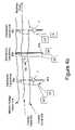
- FIG. 5is a diagram of a power line communications system, in accordance with another example embodiment of the present invention.
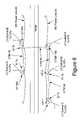
- FIG. 6is a diagram of a power line communications system, in accordance with another example embodiment of the present invention.
- FIG. 7is a functional block diagram of an example embodiment of a interface device, in accordance with an embodiment of the present invention.
- FIG. 8is a functional block diagram of an example embodiment of a communications device, in accordance with an embodiment of the present invention.
- power distribution systemstypically include components for power generation, power transmission, and power delivery.
- a transmission substationtypically is used to increase the voltage from the power generation source to high voltage (HV) levels for long distance transmission on HV transmission lines to a substation.
- HVhigh voltage
- Typical voltages found on HV transmission linesrange from 69 kilovolts (kV) to in excess of 800 kV.
- power distribution systemsinclude MV power lines and LV power lines.
- MVtypically ranges from about 1000 V to about 100 kV and LV typically ranges from about 100 V to about 240 V.
- Transformersare used to convert between the respective voltage portions, e.g., between the HV section and the MV section and between the MV section and the LV section. Transformers have a primary side for connection to a first voltage (e.g., the MV section) and a secondary side for outputting another (usually lower) voltage (e.g., the LV section).
- Such transformersare often referred to as distribution transformers or step down transformers, because they “step down” the voltage to some lower voltage. Transformers, therefore, provide voltage conversion for the power distribution system.
- poweris carried from substation transformer to a distribution transformer over one or more MV power lines. Power is carried from the distribution transformer to the customer premises via one or more LV power lines.
- a distribution transformermay function to distribute one, two, three, or more phase currents to the customer premises, depending upon the demands of the user. In the United States, for example, these local distribution transformers typically feed anywhere from one to ten homes, depending upon the concentration of the customer premises in a particular area. Distribution transformers may be pole-top transformers located on a utility pole, pad-mounted transformers located on the ground, or transformers located under ground level.
- the present inventionemploys the LV power lines, including the internal and external LV power lines associated with customer premises, and a conventional telecommunications medium (CTM) (i.e., a non-power line communications medium). Some embodiments also may employ the MV power lines. In addition, the invention may be used with overhead or underground power distribution systems.
- CTMtelecommunications medium
- a power line modemsuch as a HomePlugTM compliant modem (e.g., HomePlug 1.0 or HomePlug AV standard), interfaces the user device (such as computer, telephone, fax, etc.) to the internal LV wiring of the customer premises.
- the power line modemmay be a stand alone device or integrated into the user device.
- the power line modemcouples the data from the user device to the internal LV power lines.
- the datapropagates from the internal to the external LV power lines until reaching an interface device such as power line-coaxial interface device (PLCID) that communicatively couples the external LV power line to a conventional telecommunications medium, such as a coaxial cable or other non-power line communications medium.
- PLCIDpower line-coaxial interface device
- the interface devicereceives signals from the LV power line, such as Orthogonal Frequency Divisional Multiplexing (OFDM) signals, and communicates them through (or couples them to) the coaxial cable or other CTM.
- the interface devicereceives signals from the CTM (e.g., coaxial cable) and transmits them through (or couples them to) the LV power lines. While the ID couples data signals (which may comprises voice data, video data, internet data, or the like), it prevents the power signal of the LV power lines from being conducted to the CTM.
- OFDMOrthogonal Frequency Divisional Multiplexing
- the IDIn the upstream direction (away from the user device), the ID is in communication with a communication device that interfaces with the CTM.
- This upstream devicemay be a conventional telecommunications medium device (CTMD).
- CTMDmay interface only with conventional telecommunications medium or may additionally interface with a low and/or medium voltage power line (i.e., it may be a power line communications device).
- the interface devices (IDs)receive data from their respective user devices (e.g., via one or more power line modems) and may transmit or couple (collectively referred herein as “communicate”) the data upstream to the CTMD via the CTM.
- the CTMDreceives data from one or more IDs and, after certain processing which may take place, may transmit the data upstream toward the data's destination via a backhaul link, which may be the same, or a different, CTM or another communication link.
- the CTMDmay aggregate data from numerous IDs.
- the first upstream device to receive the data from the CTMDmay be a backhaul point, a distribution point, an aggregation point, or a point of presence—all of which may aggregate data from other CTMDs and/or other network elements.
- the CTMDmay itself provide an interface between a LV subnet and the CTM. Therefore, for those customer premises connected to the CTMD's LV subnet, the CTMD may communicate data with the user devices of those customer premises directly (as opposed to communicating the data via an ID and CTM).
- a CTMDmay act as the gateway between the CTM, its IDs and the user devices (i.e., the devices that are communicatively coupled to the LV power lines and IDs) and a backhaul link.
- the CTMDmay provide communications services for the users, which may include security management, routing of Internet protocol (IP) packets, filtering data, access control, service level monitoring, signal processing and modulation/demodulation of signals.
- IPInternet protocol
- the PLCSalso includes a backhaul point.
- the backhaul pointis an interface and gateway between the PLCS network and a traditional non-power line telecommunication network.
- One or more backhaul pointsare communicatively coupled to an aggregation point (AP) that in many embodiments may be the point of presence to the Internet.
- the backhaul pointmay be connected to the AP using any available mechanism, including fiber optic conductors, T-carrier, Synchronous Optical Network (SONET), or wireless techniques well known to those skilled in the art.
- the backhaul pointmay include a first transceiver suited for communicating via the upstream conventional communications medium and a second transceiver suited for communicating via the backhaul link.
- the APmay include a conventional Internet Protocol (IP) data packet router and may be directly connected to an Internet backbone thereby providing access to the Internet.
- IPInternet Protocol
- the APmay be connected to a core router (not shown), which provides access to the Internet, or other communication network.
- a plurality of APsmay be connected to a single core router which provides Internet access.
- the core router(or AP as the case may be) may route voice traffic to and from a voice service provider and route Internet traffic to and from an Internet service provider.
- the routing of packets to the appropriate providermay be determined by any suitable means such as by including information in the data packets to determine whether a packet is voice.
- the packetmay be routed to the voice service provider and, if not, the packet may be routed to the Internet service provider.
- the packetmay include information (which may be a portion of the address) to determine whether a packet is Internet data. If the packet is Internet data, the packet may be routed to the Internet service provider and, if not, the packet may be routed to the voice service provider.
- the distribution pointmay be a router, may be coupled to a plurality of backhaul points and provides routing functions between its backhaul points and its AP.
- a plurality of backhaul pointsare connected to each distribution point and each distribution point (of which there is a plurality) is coupled to the AP, which provides access to the Internet.
- the PLCSalso may include a power line server (PLS) that is a computer system with memory for storing a database of information about the PLCS and includes a network element manager (NEM) that monitors and controls the PLCS.
- PLSpower line server
- NEMnetwork element manager
- the PLSallows network operations personnel to provision users and network equipment, manage customer data, and monitor system status, performance and usage.
- the PLSmay reside at a remote operations center to oversee a group of communications devices via the Internet.
- the PLSmay provide an Internet identity to the network devices by assigning the devices (e.g., user devices, CTMDs, IDs (if necessary), repeaters, backhaul points, and AP) an IP address and storing the IP address and other device identifying information (e.g., the device's location, address, serial number, etc.) in its memory.
- the PLSmay approve or deny user devices authorization requests, command status reports and measurements from the CTMDs, repeaters, IDs (potentially), and backhaul points, and provide application software upgrades to the communication devices (e.g., CTMDs, IDs (potentially), backhaul points, repeaters, and other devices).
- the PLSby collecting electric power distribution information and interfacing with utilities' back-end computer systems may provide enhanced distribution services such as automated meter reading, outage detection, restoration detection, load balancing, distribution automation, Volt/Volt-Amp Reactance (Volt/VAr) management, and other similar functions.
- the PLSalso may be connected to one or more APs and/or core routers directly or through the Internet and therefore can communicate with any of the CTMDs, repeaters, IDs, user devices, and backhaul points through the respective AP and/or core router.
- the user device connected to the power line modemmay be any device cable of supplying data for transmission (or for receiving such data) including, but not limited to a computer, a telephone, a telephone answering machine, a fax, a digital cable box (e.g., for processing digital audio and video, which may then be supplied to a conventional television and for transmitting requests for video programming), a video game, a stereo, a videophone, a television (which may be a digital television), a video recording device, a home network device, a utility meter, or other device.
- the PLMtransmits the data received form the user device through the customer LV power line to an ID and provides data received from the LV power line to the user device.
- the PLMmay also be integrated with the user device, which may be a computer.
- the functions of the PLMmay be integrated into a smart utility meter such as a gas meter, electric meter, water meter, or other utility meter to thereby provide automated meter reading (AMR).
- AMRautomated meter reading
- the CTMDtypically transmits the data to the backhaul point, which, in turn, transmits the data to the AP.
- the APthen transmits the data to the appropriate destination (perhaps via a core router), which may be a network destination (such as an Internet address) in which case the packets are transmitted to, and pass through, numerous routers (herein routers are meant to include both network routers and switches) in order to arrive at the desired destination.
- a core routermay be a network destination (such as an Internet address) in which case the packets are transmitted to, and pass through, numerous routers (herein routers are meant to include both network routers and switches) in order to arrive at the desired destination.
- one or more IDsare communicatively coupled to a CTMD via a CTM.
- the IDs 7 a and 7 bwhich in this embodiment are Power Line Coaxial Interface Devices (PLCIDs), interface the LV power lines 61 to the coaxial cable 50 (i.e., the CTM).
- PLCIDsPower Line Coaxial Interface Devices
- a single LV power line 61e.g., comprised of two energized conductors and one neutral conductor
- a single LV power line 61extends from the distribution transformer 60 and, after traversing some distance, splits into numerous LV power lines with each LV power line extending to a different customer premises CP.
- all of the LV power lines extending from a distribution transformer to all of the customer premisesare referred to collectively as the LV subnet.
- a LV subnetmay service a plurality of customer premises.
- the ID 7may be coupled to the LV power line near the distribution transformer 60 and, more particularly, communicatively coupled to the LV power line prior to the place at which the LV power line splits into multiple LV power lines.
- Such an installationallows the ID 7 to be mounted to the utility pole (in overhead power line systems), provides convenient and rapid installation, and may permit a more even power distribution (i.e., propagation) of the data signals through the LV subnet.
- the IDs 7include a power signal filter (e.g., a high pass filter that may comprise one or more capacitors) to prevent the sixty hertz power signal carried by the LV power line 61 from reaching the coaxial cable 50 .
- the IDs 7may include impedance translation circuitry, for example, to provide impedance matching between the CTM (coaxial cable 50 ) and the LV power line 61 .
- the impedance translation circuitrymay be comprised of a balun transformer.
- the ID 7may be a passive device (i.e., not requiring power) comprised of the discussed filter and impedance translation circuitry.
- the ID 7may also amplify the signal, for example, via an analog amplifier circuit. For example, if each direction of communication (upstream and downstream) employs a different frequency band, the ID may have an amplifier and band pass filter for each direction of communications. Alternately, the ID 7 may regenerate the data signal which may comprise repeating the signal by receiving and processing the data (e.g., demodulating the signal, performing error correction, channel coding, etc.) and then retransmitting the signal (e.g., by modulating the signal, channel coding, etc.). All data may repeated or only select data may be repeated. In still other embodiments, in addition to the repeater functionality, the ID 7 may perform routing functions, Media Access Control (MAC), Internet Protocol (IP) address processing, and/or the other functions described below in relation to the CTMD 100 .
- MACMedia Access Control
- IPInternet Protocol
- the IDs 7are in communication with the CTMD 100 via the coaxial cable 50 .
- the CTMD 100also provides communications to the customer premises CP that are coupled to the nearby distribution transformer 60 b.
- this CTMD 100includes a first port for communicating with the LV subnet, and a second port for communicating with the coaxial cable 50 to communicate data with the IDs 7 .
- the CTMD 100communicates with an upstream device (e.g., a backhaul point) via the same coaxial cable 50 .
- the CTMD 100 and the upstream devicemay communicate in a first frequency band (referred to herein as the “backhaul link”) and the CTMD 100 and IDs 7 may communicate in a second frequency band.
- all the devicesmay use time division multiplexing or some combination of frequency division and time division multiplexing.
- the CTMD 100alternately may have a third port (and transceiver) that is communicatively coupled to the CTM for communications with the upstream device.
- the second portmay be used for all communications of the CTMD 100 on the CTM (e.g., communicating at both frequency bands through the same port/connection).
- this example embodiment of the systemmay comprise one or more CTMs 50 that communicatively couple one or more respective CTMDs 100 to a backhaul point 10 .
- CTMD 100 ais communicatively coupled to the backhaul point 10 via coaxial cable 50 a.
- CTMD 100 b and CTMD 100 calso are communicatively coupled to the backhaul point 10 via coaxial cable 50 b.
- CTMD 100 aalso is communicatively coupled to ID 7 a and ID 7 b via coaxial cable 50 a.
- ID 7 a and ID 7 zare Power Line Coaxial Interface Devices.
- Each ID 7 in the figureinterfaces a coaxial cable 50 to a LV subnet.
- ID 7 ainterfaces the LV subnet A to coaxial cable 50 a to communicatively couple the user devices in customer premises CP 1 , CP 2 , and/or CP 3 with the CTMD 100 a.
- ID 7 zinterfaces the LV subnet Z to coaxial cable 50 a to permit communications between CTMD 100 a with the user devices in the customer premises of LV subnet Z.
- CTMD 100 a, ID 7 a and its LV subnet A, and ID 7 z and its LV subnet Zare referred herein to as “CTM subnet A.”
- CTM subnet B and CTM subnet Cmay have the same components (but perhaps more or less IDs and LV subnets) and are indicated by the dotted rectangles in FIG. 3 .
- each CTM subnetis comprised of a CTMD 100 , and one or more IDs 7 , with each ID 7 providing an interface between its LV subnet and the CTM.
- the CTMDs 100 of CTM subnet B and CTM subnet Care communicatively coupled to BP 10 via coaxial cable 50 b.
- the BP 10may be coupled to one or more coaxial cables, with one or more CTMDs 100 coupled to each coaxial cable.
- each CTMDaggregates the data from one or more IDs.
- the BP 10 in this embodimentaggregates the data from the CTMDs 100 and the AP 20 aggregates the data from one or more BPs 10 .
- datais communicated between each ID 7 and its CTMD 100 in a first frequency band.
- communications between the network elements of the CTM subnetmay be time division multiplexed in the first frequency band.
- the CTMD 100may transmit, and the IDs 7 receive, in a first portion of the first frequency band and the IDs 7 may transmit, and the CTMD 100 receive, in a second portion of the first frequency band.
- Such IDsmay therefore employ frequency translation circuitry, which is well known in the art.
- This alternativealso may employ time division multiplexing among the IDs 7 and may permit full duplex communications.
- datais communicated between each CTMD 100 and the backhaul point 10 in a second frequency band.
- the backhaul point 10 and CTMDs 100 coupled to the coaxial cable 50communicate in the second frequency band via time division multiplexing (i.e., only one device coupled to the same coaxial cable is transmitting at a time).
- each CTMD 100may be allocated a different portion of the second frequency band to transmit and receive data from the upstream device (e.g., the backhaul point 10 ).
- the backhaul point 10shares the allocated portion of the second frequency band and communication in that band is achieved via time division multiplexing with each CTMD 100 (i.e., the backhaul point transmits to each CTMD 100 when that CTMD 100 is not transmitting and vice versa).
- each CTMD 100is allocated a different portion of the second frequency band (referred to herein as a CTMD band).
- each CTMD bandis further divided into a first and second sub-band.
- the CTMDtransmits data (and the backhaul point receives data) using carriers in a first frequency band of the CTMD band.
- the backhaul point 10transmits data (and the CTMD receives data) using carriers in a second frequency band of the CTMD band.
- this embodimentemploys frequency division multiplexing and may permit full duplex communications between the CTMDs 100 and the backhaul point 10 or other upstream device.
- the IDs 7 of each CTM subnetmay use different frequency bands so that the IDs of one CTM subnet do not interfere with those of another CTM subnet. Likewise, such a frequency allocation prevents the IDs 7 of one CTM subnet from communicating with the CTMD 100 of another CTM subnet and the CTMD 100 of a first CTM subnet from communicating with the IDs of another CTM subnet.
- FIGS. 4 a and 4 bare schematic representation of the embodiment that does not depict the MV power line.
- coaxial cable 50 a 1provides a communication link between the IDs 7 in CTM subnet B and their CTMD 100 b.
- coaxial cable 50 a 2provides a communication link between the IDs 7 in CTM subnet C and their CTMD 100 c.
- Coaxial cable 50 bprovides a communication link between the CTMDs 100 and the backhaul point 10 or other upstream device (e.g., distribution point, or aggregation point).
- coaxial cable 50 bprovides a backhaul link and couples a number of CTM subnets to the backhaul point 10 (or other upstream device).
- coaxial cable 50 areferred to herein as a subnet link, communicatively couples together only those network elements of a single CTM subnet.
- coaxial cable 50 a 2communicatively couples the CTMD 100 c and the three IDs 7 of CTM Subnet C together.
- the two CTMs50 a and 50 b
- the CTM forming the subnet linkcoaxial cable 50 a
- upstream data signalswill flow from the user devices (e.g., via a power line modem) through the LV power lines, through the ID 7 , through the subnet link (e.g., coaxial cable 50 a 1 or 50 a 2 ), through the corresponding CTMD 100 , through the backhaul link (e.g., coaxial cable 50 b ), to the upstream device (e.g., backhaul point 10 ).
- Downstream trafficflows from the backhaul point 10 , through the backhaul link ( 50 b ), through the addressed CTMD 100 , through the corresponding subnet link, through the ID(s) 7 , through the LV power line(s), to the addressed user device (e.g., via the power line modem).
- the IDs 7 of different CTM subnetsmay use the same frequencies because the subnet links are effectively isolated.
- the IDs 7 of different CTM subnetsare not communicatively coupled via a CTM (as in the first embodiment) and, therefore, the IDs 7 of different CTM subnets cannot interfere with each other when using the same frequency and cannot communicate with the CTMD 100 of a different CTM subnet.
- the subnet linkmay use the entire bandwidth of the CTM for communications between the IDs 7 and the CTMD 100 .
- the backhaul point 10 and the CTMDs 100may use the entire bandwidth of the backhaul link for communications.
- each CTMD 100isolates and (and couples) communications between its CTM subnets, and its subnet link, from (to) the backhaul link and backhaul point 10 .
- a CTMcommunicatively couples one or more LV subnets to the CTMD via one or more IDs.
- the CTMDcommunicates with the upstream device via the existing MV power line, which provides the backhaul link.
- a transformer bypass deviceis installed at each distribution transformer to pass data between the LV subnet and the MV power line.
- each bypass devicemay be expensive.
- coupling to the MV power linetypically requires personnel trained to work with dangerous medium voltages which may make installation costly. Consequently, a system that couples to the MV power line at fewer locations, also may be less expensive to manufacture and install.
- this embodimentincludes two IDs 7 a and 7 b that communicatively couple each of their respective LV subnets to the coaxial cable 50 .
- a CTMD 100is coupled to the coaxial cable 50 via a first port.
- a second port of the CTMD 100is coupled to the MV power line.
- Data from a user devicetraverses the LV power line and is coupled onto the coaxial cable 50 via the ID 7 .
- the datatraverses the coaxial cable and is received by the CTMD 100 , which may perform processing of the data signal.
- the CTMD 100may then transmit the data over the MV power line.
- the datatraverses the MV power line until reaching an upstream device such as a backhaul point.
- the backhaul pointmay transmit the data upstream via its upstream communication link, which may comprise a fiber optic cable, a wireless link, a twisted pair, a DSL link, a coaxial cable, an Ethernet cable, or another link.
- the power line CTMD 100receives data from the backhaul point addressed to a user device and may transmit the data downstream to the user device (e.g., by using the frequency band and/or address (if any) of the ID 7 or that corresponds to the user device). The addressed user device may then receive and utilize the data.
- data signalsmay couple across the MV conductors.
- data signals transmitted on one MV phase conductormay be present on all of the MV phase conductors due to the data coupling between the conductors.
- the backhaul point 10may not need to be physically connected to all three phase conductors of the MV cable and transmission from the backhaul point 10 when coupled to one MV phase conductor will be received by the CTMDs 100 connected to the other MV phase conductors and vice versa.
- the use of the MV power line as part of the backhaul linkmay be used in conjunction with any of the other embodiments described herein such as, for example, the embodiment shown and described in relation to FIGS. 4 a–b.
- the CTM(e.g., coaxial cable) may be used to couple together one or more LV subnets and a CTMD 100 —all of which receive power from the same MV phase conductor.
- the CTMmay be coupled to a one or more IDs 7 (a first ID group) that are coupled to LV subnets receiving power from a first MV phase conductor and a second group of IDs 7 that are coupled to LV subnets that receive power from one or more different MV phase conductors.
- a first MV power line 2 a(e.g., comprised of one to three MV phase conductors) runs parallel to (and along side) a street on a first side of the street and a second MV power line 2 b may run along the other side of the street.
- a CTM 50may be used to couple the CTMD 100 on one side of the street to one or more IDs 7 (and their respective LV subnets) on the other side of the street.
- FIG. 6illustrates two IDs 7 a and 7 b that provide communications for LV subnets that receive power from MV power line 2 b.
- IDs 7 a and 7 bare communicatively coupled to CTMD 100 (via CTM 50 ), which is also communicatively coupled to IDs 7 c and 7 d (via CTM 50 ) that have LV subnets that receive power from a different MV power line, namely MV power line 2 a.
- CTMD 100may provide communications to and receive power from LV subnet A, which also receives power from MV power line 2 a (which is different from MV power line 2 b ).
- the CTMDmay communicate with the backhaul point, for example, wirelessly, via a fiber optic cable, a twisted pair, a DSL connection, Ethernet connection, the medium voltage power line (e.g., using surface waves), or other communications medium.
- the backhaul pointfor example, wirelessly, via a fiber optic cable, a twisted pair, a DSL connection, Ethernet connection, the medium voltage power line (e.g., using surface waves), or other communications medium.
- the CTMD 100may be in communication with numerous IDs such as three, five, ten, or more PLCIDs thereby servicing six, twelve, twenty-four, or more customer premises.
- numerous CTMDseach providing communications for numerous IDs that each provide communications for numerous user devices in numerous customer premises.
- the plurality of CTMDmay be coupled to one or more backhaul points via the same and/or different communication medium (e.g., coaxial cable or fiber optic cable).
- Each CTMD(and IDs if an active device) may be coupled to the LV power line to receive power therefrom and to provide communications to the user devices of the customer premises coupled to those LV power lines.
- the CTMD and IDsmay be communicatively coupled to one or more of the energized power line conductors of the LV power line as discussed in the incorporated application.
- the LV power lineis comprised of two energized conductors and neutral conductor. After the two LV energized conductors enter the customer premises, typically only one LV energized conductor will be present at each wall socket where a power line modem might be installed (e.g., plugged in). Given this fact regarding the internal customer premises wiring, there is no way to know to which LV energized conductor the PLID (and user device) will be connected. In addition, the subscriber may move the PLID and user device to another socket to access the PLCS and the new socket may be coupled to the second (different) LV energized conductor.
- an ID 7is shown in FIG. 7 .
- the IDs 7is a passive device while other embodiments may be active devices (e.g., drawing power from the LV power line.
- This ID 7is comprised of an impedance translation circuit and a filter.
- the circuit of this embodimentis comprised of a transformer having a first winding coupled to a conductor pair 436 , which traverse through a common mode choke.
- the common mode chokeprovides a very low impedance to differential currents in the two conductors 436 a,b, but provides a significant or high impedance to common mode currents (i.e., currents traveling in the same direction such as in or out).
- each conductor 436may include a surge protection circuit, which in FIG. 7 are shown as S 1 and S 2 .
- the cable 436may be comprised of a twisted pair of conductors between the ID enclosure and LV power line.
- the twisted pair cable 436may have an impedance (determined by the geometry of the cable) as represented by Z 2 .
- This impedance Z 2may be modeled by a resistive component and an inductive component. The inductive component also may cause coupling between the two twisted wired conductors.
- the circuit of eitheralso may include a fuse in series with each conductor and a voltage limiting device, such as a pair of oppositely disposed zener diodes, coupled between the pair of conductors and may be located between the common mode choke and the transformer.
- a voltage limiting devicesuch as a pair of oppositely disposed zener diodes
- one of the conductors of the ID cable(s) 436 a or bmay used to supply power to the power supply of the ID 7 to power the ID 7 if a power supply were present (e.g., to power an amplifier, modem, processor, and/or other circuitry).
- the transformer of FIG. 7which is a balun and provides impedance matching, also has a second winding that is coupled to the coaxial cable through impedances Z 4 and conductors 13 a and 13 b.
- the balunmay be designed so that it does not communicate or transfer the power signal but does communicate the data signals and thereby provides high pass filtering.
- Both impedances Z 4 in this example embodimentare of the same value and are resistive. In other embodiments, each Z 4 may be of a different value and include a reactive component (e.g., capacitive or inductive) in order to filter the LV power signal and/or to provide the appropriate impedance matching, or other desirable circuit characteristic.
- Conductor 13 a of the ID 10is coupled to the center conductor of the coaxial cable 50 and conductor 13 b of the ID 10 is coupled to the concentric shield conductor of the coaxial cable 50 .
- the data signalis applied to the first and second LV energized conductors differentially.
- the voltage signal (representing the data) on the second LV energized conductoris equal in magnitude and opposite in polarity of the voltage on the first LV energized conductor.
- the current flow representing the data on the second LV energized conductorwill be the opposite of the current flow on the first LV energized conductor in magnitude and direction.
- the transmit circuit of this and the following embodimentsmay transmit data signals with multiple carriers (e.g., eighty or more) such as with using an Orthogonal Frequency Division Multiplex (OFDM) modulation scheme.
- OFDMOrthogonal Frequency Division Multiplex
- these embodiments of the present inventiondrive the first and second LV energized conductors differentially to transmit the data signal (e.g., using OFDM).
- the PLMtransmits data signals from the customer premises to the ID 7 by applying the data signal to one conductor (e.g., one energized conductor) referenced to the other conductor such as a ground and/or neutral.
- ID 7may include an amplifier that draws power from the low voltage power line. More specifically, the power signal from the LV power line supplies power to a power supply (e.g., that includes a rectifier and filter circuit) that powers one (for unidirectional) or two (for bi-directional) amplifiers for amplifying of the signal.
- a power supplye.g., that includes a rectifier and filter circuit
- the ID 7may further include a regeneration module that comprises a power line modem chip set circuit that communicates data via the LV power line.
- the regeneration modulecomprises a CTM transceiver.
- the CTM transceiverreceives a data input (e.g., an input from the power line modem or a router) and transmits the data via the CTM (e.g., coaxial cable).
- transmissionmay comprise filtering, modulation, error coding, channel coding, MAC processing, etc.
- the ID 7may filter, demodulate, decrypt, convert, re-modulate, and encrypt the data received from each medium for transmission onto the other medium.
- the ID 7may convert data signals from the power line that are in a first frequency band, and in a first modulation scheme to a different frequency band and different modulation scheme for transmission through the coaxial cable (and vice versa).
- the ID 7may also provide frequency shifting.
- the interface device 7may perform the same functions as those described for the CTMD below.
- some of those functionsinclude Media Access Control (MAC) processing, data filtering, routing, packet prioritizing (e.g., especially for IP telephony voice data), access control, and others.
- MACMedia Access Control
- an IDmay comprise a processor, memory, and software programming stored therein for performing those functions.
- the IDmay comprise a capacitor (and perhaps a resistor) that permits communication of the data signal but prevents communication of the power signal (e.g., forming a high pass filter).
- the example CTMD described hereinprovides bi-directional communications and may comprise a CTM interface, a transceiver, a controller, and a power supply.
- the power cablemay simply be connected to a low voltage power line (e.g., an energized and neutral conductor), which supplies power to the power supply that converts the AC signal to a DC signal for powering the components of the CTMD.
- a low voltage power linee.g., an energized and neutral conductor
- the CTM interface 283 of this example embodimentinterfaces the CTM to the CTM to provide communication to both the IDs and the upstream device, which in this embodiment is a coaxial cable. As discussed above, this may be accomplished by using a different frequency band for the upstream communications (to the backhaul point) and downstream communications (to the IDs). As shown in FIG. 8 , this embodiment may use two modems 281 and 282 (or two modem chip sets) with one providing downstream communications and the other providing upstream communications. Both modems may be identical with the appropriate frequency translation circuitry and filter to provide communications in the appropriate frequency bands.
- a single modemmay be used, for example, for a system that employed a single frequency band and time division multiplexed (TDM) communications.
- the controller 310may comprise routing functions and software executable to control the operation of the CTMD as will be discussed in more detail below.
- the CTM interfacemay be the same CTM interface as described for the ID 7 and as shown by the dashed rectangle in FIG. 7 and comprising a balun (transformer providing impedance matching), impedances Z 4 (e.g. resistors), and conductors 13 a, 13 b connected to the winding of the balun.
- a baluntransmitter providing impedance matching
- impedances Z 4e.g. resistors
- conductors 13 a, 13 bconnected to the winding of the balun.
- Other embodimentsmay employ a conventional resistor, capacitor, and/or inductor circuit to provide filtering and impedance matching.
- the CTMD 100may comprise a second CTM interface for communicating via a second CTM.
- the CTMDmay comprise a CTM interface, a controller, and a MV power line interface.
- the MV power line interfacecommunicates over the MV power line via an MV power line coupler.
- the coupling devicemay be inductive, capacitive, conductive, a combination thereof, or any suitable device for communicating data signals to and/or from the MV power line.
- the couplerin still another embodiment, includes an inductive coupling device having a toroid with windings that form part of a coupling transformer.
- the couplerincludes a power coupling device (e.g., a toroid transformer) that supplies electrical energy to a power supply to power the electronics on the MV side of the CTMD.
- the CTMD 100may include the same or different frequency filtering as its associated IDs. For example, if the IDs and CTMD 100 receive data signals in the same frequency band then the filtering may be substantially the same (i.e., TDM). If the IDs and CTMD 100 receive data signals in different frequency bands, then the filtering may be different.
- the CTMD 100may include multiple filters in order to receive data from multiple IDs and the upstream device (e.g., a backhaul point 10 ). These filters may be communicatively coupled to the same input port and transceiver or may be coupled to a different input port and transceiver.
- the CTMD 100may comprise a separate CTM transceiver (and filter) for backhaul point and for each ID (e.g., in an embodiment employing frequency division multiplexing).
- a separate CTM transceiverand filter for backhaul point and for each ID (e.g., in an embodiment employing frequency division multiplexing).
- the CTM transceiverreceives data from the CTM and may convert the data to a different format by demodulating, error decoding, channel decoding, etc. the data.
- the CTM transceiver(s)may be any transceiver(s) suitable for communicating according to the desired communication scheme and through the CTM such as, for example, a power line modem, an Ethernet modem, a DSL modem, a cable modem, a satellite modem, an 802.11 transceiver,
- the controllerincludes the hardware and software for managing communications and control of the CTMD 100 .
- the controller 310includes an IDT 32334 RISC microprocessor for running the embedded application software and also includes flash memory for storing the boot code, device data and configuration information (serial number, MAC addresses, subnet mask, and other information), the application software, routing table, and the statistical and measured data.
- This memoryincludes the program code stored therein for operating the processor to perform various applications including, for example, routing functions described herein.
- This embodiment of the controlleralso includes random access memory (RAM) for running the application software and temporary storage of data and data packets.
- RAMrandom access memory
- This embodiment of the controlleralso includes an Analog-to-Digital Converter (ADC) for taking various measurements, which may include measuring the temperature inside the CTMD 100 (through a temperature sensor such as a varistor or thermistor), for taking power quality measurements of the LV power line, detecting power outages, detecting power restoration, measuring the outputs of feedback devices, and others.
- ADCAnalog-to-Digital Converter
- the embodimentalso includes a “watchdog” timer for resetting the device should a hardware glitch or software problem prevent proper operation to continue.
- the controllermay comprise a router.
- the routerperforms prioritization, filtering, packet routing, access control, and encryption.
- the router of this example embodiment of the present inventionuses a table (e.g., a routing table) and programmed routing rules stored in memory to determine the next destination of a data packet.
- the tableis a collection of information and may include information relating to which interface leads to particular groups of addresses (such as the addresses of the user devices connected to the customer LV power lines), priorities for connections to be used, and rules for handling both routine and special cases of traffic (such as voice packets and/or control packets).
- the routerwill detect routing information, such as the destination address (e.g., the destination IP address) and/or other packet information (such as information identifying the packet as voice data), and match that routing information with rules (e.g., address rules) in the table.
- the rulesmay indicate that packets in a particular group of addresses should be transmitted in a specific direction such as through the upstream interface, the downstream interface, or be ignored (e.g., if the address does not correspond to a user device connected to the LV power line or to the CTMD 100 itself).
- the tablemay include information such as the IP addresses (and potentially the MAC addresses) of the user devices on the CTMD's LV subnets, the MAC addresses of the PLMs on the CTMD's LV subnets, the upstream subnet mask (which may include the MAC address and/or IP address of the CTMD's backhaul point 10 ), and the IP address of the CTMD's upstream transceiver and downstream transceiver.
- the routermay pass the packet to the interface for transmission. Alternately, if the IP destination address of the packet matches an IP address of the CTMD 100 , the CTMD 100 may process the packet as a command.
- the routermay prevent packets from being transmitted from the user to any destination other than a DNS server or registration server.
- the routermay replace any request for a web page received from that user device with a request for a web page on the registration server (the address of which is stored in the memory of the router).
- the routermay also prioritize transmission of packets. For example, data packets determined to be voice packets may be given higher priority for transmission through the CTMD 100 than data packets so as to reduce delays and improve the voice connection experienced by the user. Routing and/or prioritization may be based on IP addresses, MAC addresses, subscription level, or a combination thereof (e.g., the MAC address of the PLM or IP address of the user device).
- the memory of controller of the CTMD 100also includes various program code sections such as a software upgrade handler, software upgrade processing software, the PLS command processing software (which receives commands from the PLS, and processes the commands, and may return a status back to the PLS), the ADC control software, the power quality monitoring software, the error detection and alarm processing software, the data filtering software, the traffic monitoring software, the network element provisioning software, and a dynamic host configuration protocol (DHCP) Server for auto-provisioning user devices (e.g., user computers) and associated PLIDs.
- DHCPdynamic host configuration protocol
- the CTMD and ID of the above embodimentscommunicate data to user devices via the LV power line.
- the CTMD and/or IDmay use other communications mediums.
- the CTMD and/or the IDmay convert the data signals to a format for communication via a telephone line, fiber optic cable, or coaxial cable.
- Such communicationsmay be implemented in a similar fashion to the communication via the LV power line as would be well known to those skilled in the art.
- the IDwould likely be a powered device and draw power from the LV power line through a power supply to power the transceiver for the communications medium.
- the CTMD and/or IDmay convert the data signals to radio signals for communication over a wireless communication link to the user device.
- the user devicesmay be coupled to, or incorporate in, a radio transceiver for communicating through the wireless communications link.
- the wireless communications linkmay be a wireless local area network implementing a network protocol in accordance with an IEEE 802.11 (e.g., a, b, or g) standard.
- the IDmay be a powered device and draw power from the LV power line through a power supply to power the transceivers. Alternately, the ID may simply feed a functionally separate wireless radio transceiver the data signals with the wireless transceiver drawing power from the LV power line through a power supply.
- the coaxial cablemay communicate 802.11 signals and the ID may be comprised of a coaxial cable (or other CTM) interface, and a directional antenna.
- the IDmay also include a power supply, an impedance matching circuit, and an amplifier for amplifying transmitted and/or received data signals (e.g., a first and second amplifier for amplifying data signals in each frequency band that correspond to the upstream and downstream data flow).
- the CTMDmay communicate with the user devices via a fiber optic link.
- the CTMDmay convert the data signals to light signals for communication over the fiber optic link.
- the customer premisesmay have a fiber optic cable for carrying data signals, rather than using the internal wiring of customer premise.
- the type of data signal coupled by the coupling devicemay be any suitable type of data signal.
- the type of signal modulation usedcan be any suitable signal modulation used in communications (Code Division Multiple Access (CDMA), Time Division Multiple Access (TDMA), Frequency Division Multiplex (FDM), Orthogonal Frequency Division Multiplex (OFDM), and the like).
- OFDMmay be used any or all of the LV power lines, backhaul link, and CTM.
- a modulation scheme producing a wideband signal such as CDMA that is relatively flat in the spectral domainmay be used to reduce radiated interference to other systems while still delivering high data communication rates.
Landscapes
- Engineering & Computer Science (AREA)
- Power Engineering (AREA)
- Computer Networks & Wireless Communication (AREA)
- Signal Processing (AREA)
- Cable Transmission Systems, Equalization Of Radio And Reduction Of Echo (AREA)
- Small-Scale Networks (AREA)
Abstract
Description
Claims (31)
Priority Applications (2)
| Application Number | Priority Date | Filing Date | Title |
|---|---|---|---|
| US10/884,685US7098773B2 (en) | 2003-07-03 | 2004-07-02 | Power line communication system and method of operating the same |
| US11/467,591US20060291575A1 (en) | 2003-07-03 | 2006-08-28 | Power Line Communication System and Method |
Applications Claiming Priority (2)
| Application Number | Priority Date | Filing Date | Title |
|---|---|---|---|
| US48485603P | 2003-07-03 | 2003-07-03 | |
| US10/884,685US7098773B2 (en) | 2003-07-03 | 2004-07-02 | Power line communication system and method of operating the same |
Related Child Applications (1)
| Application Number | Title | Priority Date | Filing Date |
|---|---|---|---|
| US11/467,591Continuation-In-PartUS20060291575A1 (en) | 2003-07-03 | 2006-08-28 | Power Line Communication System and Method |
Publications (2)
| Publication Number | Publication Date |
|---|---|
| US20050001694A1 US20050001694A1 (en) | 2005-01-06 |
| US7098773B2true US7098773B2 (en) | 2006-08-29 |
Family
ID=34079079
Family Applications (1)
| Application Number | Title | Priority Date | Filing Date |
|---|---|---|---|
| US10/884,685Expired - Fee RelatedUS7098773B2 (en) | 2003-07-03 | 2004-07-02 | Power line communication system and method of operating the same |
Country Status (2)
| Country | Link |
|---|---|
| US (1) | US7098773B2 (en) |
| WO (2) | WO2005008902A2 (en) |
Cited By (191)
| Publication number | Priority date | Publication date | Assignee | Title |
|---|---|---|---|---|
| US20050168326A1 (en)* | 2002-12-10 | 2005-08-04 | Current Technologies, Llc | Power line repeater system and method |
| US20060038662A1 (en)* | 2002-12-10 | 2006-02-23 | White Melvin J Ii | Power line communication system and method of operating the same |
| US20060038700A1 (en)* | 2004-08-23 | 2006-02-23 | Scott Cumeralto | Sleeve repeater for forwarding meter data |
| US20060067262A1 (en)* | 2004-09-20 | 2006-03-30 | Troemel Hans A Jr | Apparatus having and method for implementing a distributed architecture for receiving and/or transmitting radio frequency signals |
| US20060097573A1 (en)* | 2004-10-26 | 2006-05-11 | Gidge Brett D | Power line communications system and method of operating the same |
| US20060187022A1 (en)* | 2005-02-22 | 2006-08-24 | Dawson Thomas P | PLC intercom / monitor |
| US20060220833A1 (en)* | 2005-04-04 | 2006-10-05 | Berkman William H | Power line communications system and method |
| US20060291575A1 (en)* | 2003-07-03 | 2006-12-28 | Berkman William H | Power Line Communication System and Method |
| US20070053352A1 (en)* | 2005-09-06 | 2007-03-08 | Corcoran Kevin F | Power line communications system with differentiated data services |
| US20070052850A1 (en)* | 2005-08-23 | 2007-03-08 | David Vinson | Low overhead audio/video intercom system |
| US20070136766A1 (en)* | 2005-12-09 | 2007-06-14 | Ryuichi Iwamura | Cross-phase adapter for powerline communications (PLC) network |
| US20070217414A1 (en)* | 2006-03-14 | 2007-09-20 | Berkman William H | System and method for multicasting over power lines |
| US20070293955A1 (en)* | 2004-09-02 | 2007-12-20 | Misubishi Material Corporation | Audio/Visual Data Communication System, Audio/Visual Data Transmitting Device, And Audio/Visual Data Reproducing Device |
| US20080195259A1 (en)* | 2007-02-08 | 2008-08-14 | Davis Terry L | Methods and systems for high speed data communication |
| US7715534B2 (en) | 2000-03-20 | 2010-05-11 | Mosaid Technologies Incorporated | Telephone outlet for implementing a local area network over telephone lines and a local area network using such outlets |
| US7764943B2 (en) | 2006-03-27 | 2010-07-27 | Current Technologies, Llc | Overhead and underground power line communication system and method using a bypass |
| US7852874B2 (en) | 1998-07-28 | 2010-12-14 | Mosaid Technologies Incorporated | Local area network of serial intelligent cells |
| US7873058B2 (en) | 2004-11-08 | 2011-01-18 | Mosaid Technologies Incorporated | Outlet with analog signal adapter, a method for use thereof and a network using said outlet |
| US7876767B2 (en) | 2000-04-19 | 2011-01-25 | Mosaid Technologies Incorporated | Network combining wired and non-wired segments |
| US20110018704A1 (en)* | 2009-07-24 | 2011-01-27 | Burrows Zachary M | System, Device and Method for Providing Power Line Communications |
| US7881462B2 (en) | 2004-02-16 | 2011-02-01 | Mosaid Technologies Incorporated | Outlet add-on module |
| US7990908B2 (en) | 2002-11-13 | 2011-08-02 | Mosaid Technologies Incorporated | Addressable outlet, and a network using the same |
| US8279058B2 (en) | 2008-11-06 | 2012-10-02 | Current Technologies International Gmbh | System, device and method for communicating over power lines |
| US20140236394A1 (en)* | 2013-02-18 | 2014-08-21 | The Boeing Company | Methods and systems for aircraft data communications over heterogeneous connectivity |
| US8923339B2 (en) | 2011-03-06 | 2014-12-30 | PCN Technology, Inc. | Systems and methods of data transmission and management |
| US9119127B1 (en) | 2012-12-05 | 2015-08-25 | At&T Intellectual Property I, Lp | Backhaul link for distributed antenna system |
| US9154966B2 (en) | 2013-11-06 | 2015-10-06 | At&T Intellectual Property I, Lp | Surface-wave communications and methods thereof |
| US9209902B2 (en) | 2013-12-10 | 2015-12-08 | At&T Intellectual Property I, L.P. | Quasi-optical coupler |
| US9312919B1 (en) | 2014-10-21 | 2016-04-12 | At&T Intellectual Property I, Lp | Transmission device with impairment compensation and methods for use therewith |
| US9420515B2 (en) | 2011-10-18 | 2016-08-16 | Itron, Inc. | Endpoint repeater functionality selection |
| US9461706B1 (en) | 2015-07-31 | 2016-10-04 | At&T Intellectual Property I, Lp | Method and apparatus for exchanging communication signals |
| US9490869B1 (en) | 2015-05-14 | 2016-11-08 | At&T Intellectual Property I, L.P. | Transmission medium having multiple cores and methods for use therewith |
| US9503189B2 (en) | 2014-10-10 | 2016-11-22 | At&T Intellectual Property I, L.P. | Method and apparatus for arranging communication sessions in a communication system |
| US9509415B1 (en) | 2015-06-25 | 2016-11-29 | At&T Intellectual Property I, L.P. | Methods and apparatus for inducing a fundamental wave mode on a transmission medium |
| US9520945B2 (en) | 2014-10-21 | 2016-12-13 | At&T Intellectual Property I, L.P. | Apparatus for providing communication services and methods thereof |
| US9525524B2 (en) | 2013-05-31 | 2016-12-20 | At&T Intellectual Property I, L.P. | Remote distributed antenna system |
| US9525210B2 (en) | 2014-10-21 | 2016-12-20 | At&T Intellectual Property I, L.P. | Guided-wave transmission device with non-fundamental mode propagation and methods for use therewith |
| US9531427B2 (en) | 2014-11-20 | 2016-12-27 | At&T Intellectual Property I, L.P. | Transmission device with mode division multiplexing and methods for use therewith |
| US9564947B2 (en) | 2014-10-21 | 2017-02-07 | At&T Intellectual Property I, L.P. | Guided-wave transmission device with diversity and methods for use therewith |
| US9577307B2 (en) | 2014-10-21 | 2017-02-21 | At&T Intellectual Property I, L.P. | Guided-wave transmission device and methods for use therewith |
| US9608692B2 (en) | 2015-06-11 | 2017-03-28 | At&T Intellectual Property I, L.P. | Repeater and methods for use therewith |
| US9608740B2 (en) | 2015-07-15 | 2017-03-28 | At&T Intellectual Property I, L.P. | Method and apparatus for launching a wave mode that mitigates interference |
| US9615269B2 (en) | 2014-10-02 | 2017-04-04 | At&T Intellectual Property I, L.P. | Method and apparatus that provides fault tolerance in a communication network |
| US9628116B2 (en) | 2015-07-14 | 2017-04-18 | At&T Intellectual Property I, L.P. | Apparatus and methods for transmitting wireless signals |
| US9628854B2 (en) | 2014-09-29 | 2017-04-18 | At&T Intellectual Property I, L.P. | Method and apparatus for distributing content in a communication network |
| US9640850B2 (en) | 2015-06-25 | 2017-05-02 | At&T Intellectual Property I, L.P. | Methods and apparatus for inducing a non-fundamental wave mode on a transmission medium |
| US9653770B2 (en) | 2014-10-21 | 2017-05-16 | At&T Intellectual Property I, L.P. | Guided wave coupler, coupling module and methods for use therewith |
| US9654173B2 (en) | 2014-11-20 | 2017-05-16 | At&T Intellectual Property I, L.P. | Apparatus for powering a communication device and methods thereof |
| US9667317B2 (en) | 2015-06-15 | 2017-05-30 | At&T Intellectual Property I, L.P. | Method and apparatus for providing security using network traffic adjustments |
| US9680670B2 (en) | 2014-11-20 | 2017-06-13 | At&T Intellectual Property I, L.P. | Transmission device with channel equalization and control and methods for use therewith |
| US9685992B2 (en) | 2014-10-03 | 2017-06-20 | At&T Intellectual Property I, L.P. | Circuit panel network and methods thereof |
| US9692101B2 (en) | 2014-08-26 | 2017-06-27 | At&T Intellectual Property I, L.P. | Guided wave couplers for coupling electromagnetic waves between a waveguide surface and a surface of a wire |
| US9705571B2 (en) | 2015-09-16 | 2017-07-11 | At&T Intellectual Property I, L.P. | Method and apparatus for use with a radio distributed antenna system |
| US9705561B2 (en) | 2015-04-24 | 2017-07-11 | At&T Intellectual Property I, L.P. | Directional coupling device and methods for use therewith |
| US9722318B2 (en) | 2015-07-14 | 2017-08-01 | At&T Intellectual Property I, L.P. | Method and apparatus for coupling an antenna to a device |
| US9729197B2 (en) | 2015-10-01 | 2017-08-08 | At&T Intellectual Property I, L.P. | Method and apparatus for communicating network management traffic over a network |
| US9735833B2 (en) | 2015-07-31 | 2017-08-15 | At&T Intellectual Property I, L.P. | Method and apparatus for communications management in a neighborhood network |
| US9742462B2 (en) | 2014-12-04 | 2017-08-22 | At&T Intellectual Property I, L.P. | Transmission medium and communication interfaces and methods for use therewith |
| US9749013B2 (en) | 2015-03-17 | 2017-08-29 | At&T Intellectual Property I, L.P. | Method and apparatus for reducing attenuation of electromagnetic waves guided by a transmission medium |
| US9749053B2 (en) | 2015-07-23 | 2017-08-29 | At&T Intellectual Property I, L.P. | Node device, repeater and methods for use therewith |
| US9748626B2 (en) | 2015-05-14 | 2017-08-29 | At&T Intellectual Property I, L.P. | Plurality of cables having different cross-sectional shapes which are bundled together to form a transmission medium |
| US9755697B2 (en) | 2014-09-15 | 2017-09-05 | At&T Intellectual Property I, L.P. | Method and apparatus for sensing a condition in a transmission medium of electromagnetic waves |
| US9762289B2 (en) | 2014-10-14 | 2017-09-12 | At&T Intellectual Property I, L.P. | Method and apparatus for transmitting or receiving signals in a transportation system |
| US9769020B2 (en) | 2014-10-21 | 2017-09-19 | At&T Intellectual Property I, L.P. | Method and apparatus for responding to events affecting communications in a communication network |
| US9769128B2 (en) | 2015-09-28 | 2017-09-19 | At&T Intellectual Property I, L.P. | Method and apparatus for encryption of communications over a network |
| US9780834B2 (en) | 2014-10-21 | 2017-10-03 | At&T Intellectual Property I, L.P. | Method and apparatus for transmitting electromagnetic waves |
| US9793954B2 (en) | 2015-04-28 | 2017-10-17 | At&T Intellectual Property I, L.P. | Magnetic coupling device and methods for use therewith |
| US9793951B2 (en) | 2015-07-15 | 2017-10-17 | At&T Intellectual Property I, L.P. | Method and apparatus for launching a wave mode that mitigates interference |
| US9793955B2 (en) | 2015-04-24 | 2017-10-17 | At&T Intellectual Property I, Lp | Passive electrical coupling device and methods for use therewith |
| US9800327B2 (en) | 2014-11-20 | 2017-10-24 | At&T Intellectual Property I, L.P. | Apparatus for controlling operations of a communication device and methods thereof |
| US9820146B2 (en) | 2015-06-12 | 2017-11-14 | At&T Intellectual Property I, L.P. | Method and apparatus for authentication and identity management of communicating devices |
| US9838896B1 (en) | 2016-12-09 | 2017-12-05 | At&T Intellectual Property I, L.P. | Method and apparatus for assessing network coverage |
| US9836957B2 (en) | 2015-07-14 | 2017-12-05 | At&T Intellectual Property I, L.P. | Method and apparatus for communicating with premises equipment |
| US9847850B2 (en) | 2014-10-14 | 2017-12-19 | At&T Intellectual Property I, L.P. | Method and apparatus for adjusting a mode of communication in a communication network |
| US9847566B2 (en) | 2015-07-14 | 2017-12-19 | At&T Intellectual Property I, L.P. | Method and apparatus for adjusting a field of a signal to mitigate interference |
| US9853342B2 (en) | 2015-07-14 | 2017-12-26 | At&T Intellectual Property I, L.P. | Dielectric transmission medium connector and methods for use therewith |
| US9860075B1 (en) | 2016-08-26 | 2018-01-02 | At&T Intellectual Property I, L.P. | Method and communication node for broadband distribution |
| US9865911B2 (en) | 2015-06-25 | 2018-01-09 | At&T Intellectual Property I, L.P. | Waveguide system for slot radiating first electromagnetic waves that are combined into a non-fundamental wave mode second electromagnetic wave on a transmission medium |
| US9866309B2 (en) | 2015-06-03 | 2018-01-09 | At&T Intellectual Property I, Lp | Host node device and methods for use therewith |
| US9871282B2 (en) | 2015-05-14 | 2018-01-16 | At&T Intellectual Property I, L.P. | At least one transmission medium having a dielectric surface that is covered at least in part by a second dielectric |
| US9871283B2 (en) | 2015-07-23 | 2018-01-16 | At&T Intellectual Property I, Lp | Transmission medium having a dielectric core comprised of plural members connected by a ball and socket configuration |
| US9876571B2 (en) | 2015-02-20 | 2018-01-23 | At&T Intellectual Property I, Lp | Guided-wave transmission device with non-fundamental mode propagation and methods for use therewith |
| US9876264B2 (en) | 2015-10-02 | 2018-01-23 | At&T Intellectual Property I, Lp | Communication system, guided wave switch and methods for use therewith |
| US9876605B1 (en) | 2016-10-21 | 2018-01-23 | At&T Intellectual Property I, L.P. | Launcher and coupling system to support desired guided wave mode |
| US9882257B2 (en) | 2015-07-14 | 2018-01-30 | At&T Intellectual Property I, L.P. | Method and apparatus for launching a wave mode that mitigates interference |
| US9882277B2 (en) | 2015-10-02 | 2018-01-30 | At&T Intellectual Property I, Lp | Communication device and antenna assembly with actuated gimbal mount |
| US9893795B1 (en) | 2016-12-07 | 2018-02-13 | At&T Intellectual Property I, Lp | Method and repeater for broadband distribution |
| US9906269B2 (en) | 2014-09-17 | 2018-02-27 | At&T Intellectual Property I, L.P. | Monitoring and mitigating conditions in a communication network |
| US9904535B2 (en) | 2015-09-14 | 2018-02-27 | At&T Intellectual Property I, L.P. | Method and apparatus for distributing software |
| US9913139B2 (en) | 2015-06-09 | 2018-03-06 | At&T Intellectual Property I, L.P. | Signal fingerprinting for authentication of communicating devices |
| US9912419B1 (en) | 2016-08-24 | 2018-03-06 | At&T Intellectual Property I, L.P. | Method and apparatus for managing a fault in a distributed antenna system |
| US9911020B1 (en) | 2016-12-08 | 2018-03-06 | At&T Intellectual Property I, L.P. | Method and apparatus for tracking via a radio frequency identification device |
| US9912381B2 (en) | 2015-06-03 | 2018-03-06 | At&T Intellectual Property I, Lp | Network termination and methods for use therewith |
| US9912027B2 (en) | 2015-07-23 | 2018-03-06 | At&T Intellectual Property I, L.P. | Method and apparatus for exchanging communication signals |
| US9917341B2 (en) | 2015-05-27 | 2018-03-13 | At&T Intellectual Property I, L.P. | Apparatus and method for launching electromagnetic waves and for modifying radial dimensions of the propagating electromagnetic waves |
| US9927517B1 (en) | 2016-12-06 | 2018-03-27 | At&T Intellectual Property I, L.P. | Apparatus and methods for sensing rainfall |
| US9948354B2 (en) | 2015-04-28 | 2018-04-17 | At&T Intellectual Property I, L.P. | Magnetic coupling device with reflective plate and methods for use therewith |
| US9948333B2 (en) | 2015-07-23 | 2018-04-17 | At&T Intellectual Property I, L.P. | Method and apparatus for wireless communications to mitigate interference |
| US9954287B2 (en) | 2014-11-20 | 2018-04-24 | At&T Intellectual Property I, L.P. | Apparatus for converting wireless signals and electromagnetic waves and methods thereof |
| US9967173B2 (en) | 2015-07-31 | 2018-05-08 | At&T Intellectual Property I, L.P. | Method and apparatus for authentication and identity management of communicating devices |
| US9973940B1 (en) | 2017-02-27 | 2018-05-15 | At&T Intellectual Property I, L.P. | Apparatus and methods for dynamic impedance matching of a guided wave launcher |
| US9991580B2 (en) | 2016-10-21 | 2018-06-05 | At&T Intellectual Property I, L.P. | Launcher and coupling system for guided wave mode cancellation |
| US9998870B1 (en) | 2016-12-08 | 2018-06-12 | At&T Intellectual Property I, L.P. | Method and apparatus for proximity sensing |
| US9999038B2 (en) | 2013-05-31 | 2018-06-12 | At&T Intellectual Property I, L.P. | Remote distributed antenna system |
| US9997819B2 (en) | 2015-06-09 | 2018-06-12 | At&T Intellectual Property I, L.P. | Transmission medium and method for facilitating propagation of electromagnetic waves via a core |
| US10009901B2 (en) | 2015-09-16 | 2018-06-26 | At&T Intellectual Property I, L.P. | Method, apparatus, and computer-readable storage medium for managing utilization of wireless resources between base stations |
| US10009063B2 (en) | 2015-09-16 | 2018-06-26 | At&T Intellectual Property I, L.P. | Method and apparatus for use with a radio distributed antenna system having an out-of-band reference signal |
| US10009065B2 (en) | 2012-12-05 | 2018-06-26 | At&T Intellectual Property I, L.P. | Backhaul link for distributed antenna system |
| US10009067B2 (en) | 2014-12-04 | 2018-06-26 | At&T Intellectual Property I, L.P. | Method and apparatus for configuring a communication interface |
| US10020844B2 (en) | 2016-12-06 | 2018-07-10 | T&T Intellectual Property I, L.P. | Method and apparatus for broadcast communication via guided waves |
| US10020587B2 (en) | 2015-07-31 | 2018-07-10 | At&T Intellectual Property I, L.P. | Radial antenna and methods for use therewith |
| US10027397B2 (en) | 2016-12-07 | 2018-07-17 | At&T Intellectual Property I, L.P. | Distributed antenna system and methods for use therewith |
| US10033108B2 (en) | 2015-07-14 | 2018-07-24 | At&T Intellectual Property I, L.P. | Apparatus and methods for generating an electromagnetic wave having a wave mode that mitigates interference |
| US10033107B2 (en) | 2015-07-14 | 2018-07-24 | At&T Intellectual Property I, L.P. | Method and apparatus for coupling an antenna to a device |
| US10044409B2 (en) | 2015-07-14 | 2018-08-07 | At&T Intellectual Property I, L.P. | Transmission medium and methods for use therewith |
| US10051629B2 (en) | 2015-09-16 | 2018-08-14 | At&T Intellectual Property I, L.P. | Method and apparatus for use with a radio distributed antenna system having an in-band reference signal |
| US10051483B2 (en) | 2015-10-16 | 2018-08-14 | At&T Intellectual Property I, L.P. | Method and apparatus for directing wireless signals |
| US10069535B2 (en) | 2016-12-08 | 2018-09-04 | At&T Intellectual Property I, L.P. | Apparatus and methods for launching electromagnetic waves having a certain electric field structure |
| US10074890B2 (en) | 2015-10-02 | 2018-09-11 | At&T Intellectual Property I, L.P. | Communication device and antenna with integrated light assembly |
| US10079661B2 (en) | 2015-09-16 | 2018-09-18 | At&T Intellectual Property I, L.P. | Method and apparatus for use with a radio distributed antenna system having a clock reference |
| US10090606B2 (en) | 2015-07-15 | 2018-10-02 | At&T Intellectual Property I, L.P. | Antenna system with dielectric array and methods for use therewith |
| US10090594B2 (en) | 2016-11-23 | 2018-10-02 | At&T Intellectual Property I, L.P. | Antenna system having structural configurations for assembly |
| US10103422B2 (en) | 2016-12-08 | 2018-10-16 | At&T Intellectual Property I, L.P. | Method and apparatus for mounting network devices |
| US10103801B2 (en) | 2015-06-03 | 2018-10-16 | At&T Intellectual Property I, L.P. | Host node device and methods for use therewith |
| US10135147B2 (en) | 2016-10-18 | 2018-11-20 | At&T Intellectual Property I, L.P. | Apparatus and methods for launching guided waves via an antenna |
| US10136434B2 (en) | 2015-09-16 | 2018-11-20 | At&T Intellectual Property I, L.P. | Method and apparatus for use with a radio distributed antenna system having an ultra-wideband control channel |
| US10135145B2 (en) | 2016-12-06 | 2018-11-20 | At&T Intellectual Property I, L.P. | Apparatus and methods for generating an electromagnetic wave along a transmission medium |
| US10135146B2 (en) | 2016-10-18 | 2018-11-20 | At&T Intellectual Property I, L.P. | Apparatus and methods for launching guided waves via circuits |
| US10142086B2 (en) | 2015-06-11 | 2018-11-27 | At&T Intellectual Property I, L.P. | Repeater and methods for use therewith |
| US10139820B2 (en) | 2016-12-07 | 2018-11-27 | At&T Intellectual Property I, L.P. | Method and apparatus for deploying equipment of a communication system |
| US10144036B2 (en) | 2015-01-30 | 2018-12-04 | At&T Intellectual Property I, L.P. | Method and apparatus for mitigating interference affecting a propagation of electromagnetic waves guided by a transmission medium |
| US10148016B2 (en) | 2015-07-14 | 2018-12-04 | At&T Intellectual Property I, L.P. | Apparatus and methods for communicating utilizing an antenna array |
| US10154493B2 (en) | 2015-06-03 | 2018-12-11 | At&T Intellectual Property I, L.P. | Network termination and methods for use therewith |
| US10170840B2 (en) | 2015-07-14 | 2019-01-01 | At&T Intellectual Property I, L.P. | Apparatus and methods for sending or receiving electromagnetic signals |
| US10168695B2 (en) | 2016-12-07 | 2019-01-01 | At&T Intellectual Property I, L.P. | Method and apparatus for controlling an unmanned aircraft |
| US10178445B2 (en) | 2016-11-23 | 2019-01-08 | At&T Intellectual Property I, L.P. | Methods, devices, and systems for load balancing between a plurality of waveguides |
| US10205655B2 (en) | 2015-07-14 | 2019-02-12 | At&T Intellectual Property I, L.P. | Apparatus and methods for communicating utilizing an antenna array and multiple communication paths |
| US10224634B2 (en) | 2016-11-03 | 2019-03-05 | At&T Intellectual Property I, L.P. | Methods and apparatus for adjusting an operational characteristic of an antenna |
| US10225025B2 (en) | 2016-11-03 | 2019-03-05 | At&T Intellectual Property I, L.P. | Method and apparatus for detecting a fault in a communication system |
| US10243784B2 (en) | 2014-11-20 | 2019-03-26 | At&T Intellectual Property I, L.P. | System for generating topology information and methods thereof |
| US10243270B2 (en) | 2016-12-07 | 2019-03-26 | At&T Intellectual Property I, L.P. | Beam adaptive multi-feed dielectric antenna system and methods for use therewith |
| US10264586B2 (en) | 2016-12-09 | 2019-04-16 | At&T Mobility Ii Llc | Cloud-based packet controller and methods for use therewith |
| US10291311B2 (en) | 2016-09-09 | 2019-05-14 | At&T Intellectual Property I, L.P. | Method and apparatus for mitigating a fault in a distributed antenna system |
| US10291334B2 (en) | 2016-11-03 | 2019-05-14 | At&T Intellectual Property I, L.P. | System for detecting a fault in a communication system |
| US10298293B2 (en) | 2017-03-13 | 2019-05-21 | At&T Intellectual Property I, L.P. | Apparatus of communication utilizing wireless network devices |
| US10305190B2 (en) | 2016-12-01 | 2019-05-28 | At&T Intellectual Property I, L.P. | Reflecting dielectric antenna system and methods for use therewith |
| US10312567B2 (en) | 2016-10-26 | 2019-06-04 | At&T Intellectual Property I, L.P. | Launcher with planar strip antenna and methods for use therewith |
| US10320586B2 (en) | 2015-07-14 | 2019-06-11 | At&T Intellectual Property I, L.P. | Apparatus and methods for generating non-interfering electromagnetic waves on an insulated transmission medium |
| US10326494B2 (en) | 2016-12-06 | 2019-06-18 | At&T Intellectual Property I, L.P. | Apparatus for measurement de-embedding and methods for use therewith |
| US10326689B2 (en) | 2016-12-08 | 2019-06-18 | At&T Intellectual Property I, L.P. | Method and system for providing alternative communication paths |
| US10340603B2 (en) | 2016-11-23 | 2019-07-02 | At&T Intellectual Property I, L.P. | Antenna system having shielded structural configurations for assembly |
| US10340600B2 (en) | 2016-10-18 | 2019-07-02 | At&T Intellectual Property I, L.P. | Apparatus and methods for launching guided waves via plural waveguide systems |
| US10340601B2 (en) | 2016-11-23 | 2019-07-02 | At&T Intellectual Property I, L.P. | Multi-antenna system and methods for use therewith |
| US10340573B2 (en) | 2016-10-26 | 2019-07-02 | At&T Intellectual Property I, L.P. | Launcher with cylindrical coupling device and methods for use therewith |
| US10340983B2 (en) | 2016-12-09 | 2019-07-02 | At&T Intellectual Property I, L.P. | Method and apparatus for surveying remote sites via guided wave communications |
| US10341142B2 (en) | 2015-07-14 | 2019-07-02 | At&T Intellectual Property I, L.P. | Apparatus and methods for generating non-interfering electromagnetic waves on an uninsulated conductor |
| US10348391B2 (en) | 2015-06-03 | 2019-07-09 | At&T Intellectual Property I, L.P. | Client node device with frequency conversion and methods for use therewith |
| US10355367B2 (en) | 2015-10-16 | 2019-07-16 | At&T Intellectual Property I, L.P. | Antenna structure for exchanging wireless signals |
| US10361489B2 (en) | 2016-12-01 | 2019-07-23 | At&T Intellectual Property I, L.P. | Dielectric dish antenna system and methods for use therewith |
| US10359749B2 (en) | 2016-12-07 | 2019-07-23 | At&T Intellectual Property I, L.P. | Method and apparatus for utilities management via guided wave communication |
| US10374316B2 (en) | 2016-10-21 | 2019-08-06 | At&T Intellectual Property I, L.P. | System and dielectric antenna with non-uniform dielectric |
| US10382976B2 (en) | 2016-12-06 | 2019-08-13 | At&T Intellectual Property I, L.P. | Method and apparatus for managing wireless communications based on communication paths and network device positions |
| US10389029B2 (en) | 2016-12-07 | 2019-08-20 | At&T Intellectual Property I, L.P. | Multi-feed dielectric antenna system with core selection and methods for use therewith |
| US10389037B2 (en) | 2016-12-08 | 2019-08-20 | At&T Intellectual Property I, L.P. | Apparatus and methods for selecting sections of an antenna array and use therewith |
| US10396887B2 (en) | 2015-06-03 | 2019-08-27 | At&T Intellectual Property I, L.P. | Client node device and methods for use therewith |
| US10411356B2 (en) | 2016-12-08 | 2019-09-10 | At&T Intellectual Property I, L.P. | Apparatus and methods for selectively targeting communication devices with an antenna array |
| US10439675B2 (en) | 2016-12-06 | 2019-10-08 | At&T Intellectual Property I, L.P. | Method and apparatus for repeating guided wave communication signals |
| US10446936B2 (en) | 2016-12-07 | 2019-10-15 | At&T Intellectual Property I, L.P. | Multi-feed dielectric antenna system and methods for use therewith |
| US10498044B2 (en) | 2016-11-03 | 2019-12-03 | At&T Intellectual Property I, L.P. | Apparatus for configuring a surface of an antenna |
| US10530505B2 (en) | 2016-12-08 | 2020-01-07 | At&T Intellectual Property I, L.P. | Apparatus and methods for launching electromagnetic waves along a transmission medium |
| US10535928B2 (en) | 2016-11-23 | 2020-01-14 | At&T Intellectual Property I, L.P. | Antenna system and methods for use therewith |
| US10547348B2 (en) | 2016-12-07 | 2020-01-28 | At&T Intellectual Property I, L.P. | Method and apparatus for switching transmission mediums in a communication system |
| US10601494B2 (en) | 2016-12-08 | 2020-03-24 | At&T Intellectual Property I, L.P. | Dual-band communication device and method for use therewith |
| US10637149B2 (en) | 2016-12-06 | 2020-04-28 | At&T Intellectual Property I, L.P. | Injection molded dielectric antenna and methods for use therewith |
| US10650940B2 (en) | 2015-05-15 | 2020-05-12 | At&T Intellectual Property I, L.P. | Transmission medium having a conductive material and methods for use therewith |
| US10665942B2 (en) | 2015-10-16 | 2020-05-26 | At&T Intellectual Property I, L.P. | Method and apparatus for adjusting wireless communications |
| US10679767B2 (en) | 2015-05-15 | 2020-06-09 | At&T Intellectual Property I, L.P. | Transmission medium having a conductive material and methods for use therewith |
| US20200187110A1 (en)* | 2016-03-14 | 2020-06-11 | Robert Bosch Gmbh | Distributed wireless intercom audio routing over ethernet with synchornization and roaming |
| US10694379B2 (en) | 2016-12-06 | 2020-06-23 | At&T Intellectual Property I, L.P. | Waveguide system with device-based authentication and methods for use therewith |
| US10727599B2 (en) | 2016-12-06 | 2020-07-28 | At&T Intellectual Property I, L.P. | Launcher with slot antenna and methods for use therewith |
| US10755542B2 (en) | 2016-12-06 | 2020-08-25 | At&T Intellectual Property I, L.P. | Method and apparatus for surveillance via guided wave communication |
| US10777873B2 (en) | 2016-12-08 | 2020-09-15 | At&T Intellectual Property I, L.P. | Method and apparatus for mounting network devices |
| US10784670B2 (en) | 2015-07-23 | 2020-09-22 | At&T Intellectual Property I, L.P. | Antenna support for aligning an antenna |
| US10811767B2 (en) | 2016-10-21 | 2020-10-20 | At&T Intellectual Property I, L.P. | System and dielectric antenna with convex dielectric radome |
| US10819035B2 (en) | 2016-12-06 | 2020-10-27 | At&T Intellectual Property I, L.P. | Launcher with helical antenna and methods for use therewith |
| US20200351389A1 (en)* | 2014-11-04 | 2020-11-05 | Texas Instruments Incorporated | Automatic Selection of MAC Protocol to Support Multiple Prime PLC Standards |
| US10916969B2 (en) | 2016-12-08 | 2021-02-09 | At&T Intellectual Property I, L.P. | Method and apparatus for providing power using an inductive coupling |
| US10938108B2 (en) | 2016-12-08 | 2021-03-02 | At&T Intellectual Property I, L.P. | Frequency selective multi-feed dielectric antenna system and methods for use therewith |
| US11032819B2 (en) | 2016-09-15 | 2021-06-08 | At&T Intellectual Property I, L.P. | Method and apparatus for use with a radio distributed antenna system having a control channel reference signal |
| US11323435B2 (en) | 2019-05-08 | 2022-05-03 | The Boeing Company | Method and apparatus for advanced security systems over a power line connection |
| US12217596B2 (en) | 2021-10-20 | 2025-02-04 | Erico International Corporation | Monitor system for surge protection devices |
Families Citing this family (16)
| Publication number | Priority date | Publication date | Assignee | Title |
|---|---|---|---|---|
| US8090857B2 (en) | 2003-11-24 | 2012-01-03 | Qualcomm Atheros, Inc. | Medium access control layer that encapsulates data from a plurality of received data units into a plurality of independently transmittable blocks |
| US20110110459A1 (en)* | 2004-02-02 | 2011-05-12 | Satius Holding, Inc. | FM OFDM over various communication media |
| US11152971B2 (en)* | 2004-02-02 | 2021-10-19 | Charles Abraham | Frequency modulated OFDM over various communication media |
| US7391317B2 (en)* | 2004-09-08 | 2008-06-24 | Satius, Inc. | Apparatus and method for transmitting digital data over various communication media |
| US8175190B2 (en)* | 2005-07-27 | 2012-05-08 | Qualcomm Atheros, Inc. | Managing spectra of modulated signals in a communication network |
| US7729372B2 (en)* | 2005-07-27 | 2010-06-01 | Sharp Corporation | Communicating in a network that includes a medium having varying transmission characteristics |
| US20070036171A1 (en) | 2005-08-10 | 2007-02-15 | Magin Gregory A | Bridging coaxial cable networks |
| US8031758B2 (en) | 2006-03-14 | 2011-10-04 | Sony Corporation | Powerline communication (PLC) modem employing an analog electromagnetic transducer |
| EP1892843B1 (en)* | 2006-08-24 | 2014-10-01 | Sony Deutschland GmbH | Method for transmitting a signal on a power line network, transmitting unit, receiving unit and system |
| JP5274769B2 (en)* | 2006-12-25 | 2013-08-28 | 株式会社東芝 | Equipment usage status management system |
| US9413686B2 (en)* | 2007-06-04 | 2016-08-09 | Qualcomm Incorporated | Establishing a unique end-to-end management key |
| WO2010005733A1 (en) | 2008-06-16 | 2010-01-14 | Yonge Lawrence W | Managing coexistence among signaling protocols on a shared medium |
| US8301314B2 (en)* | 2009-01-29 | 2012-10-30 | S&C Electric Company | System and method for providing voltage regulation in a power distribution network |
| US9385782B1 (en) | 2010-01-08 | 2016-07-05 | Qualcomm Incorporated | Communication between network nodes |
| CN107945539B (en)* | 2017-08-28 | 2020-10-16 | 北京工业大学 | A kind of intersection signal control method |
| US11477283B2 (en)* | 2020-05-05 | 2022-10-18 | Dell Products L.P. | Remote server management using a power line network |
Citations (47)
| Publication number | Priority date | Publication date | Assignee | Title |
|---|---|---|---|---|
| US3702460A (en) | 1971-11-30 | 1972-11-07 | John B Blose | Communications system for electric power utility |
| US3810096A (en) | 1972-09-14 | 1974-05-07 | Integrated Syst Co | Method and system for transmitting data and indicating room status |
| US3846638A (en) | 1972-10-02 | 1974-11-05 | Gen Electric | Improved coupling arrangement for power line carrier systems |
| US4012733A (en) | 1975-10-16 | 1977-03-15 | Westinghouse Electric Corporation | Distribution power line communication system including a messenger wire communications link |
| US4016429A (en) | 1976-01-16 | 1977-04-05 | Westinghouse Electric Corporation | Power line carrier communication system for signaling customer locations through ground wire conductors |
| US4475209A (en) | 1982-04-23 | 1984-10-02 | Westinghouse Electric Corp. | Regenerator for an intrabundle power-line communication system |
| US4569045A (en) | 1983-06-06 | 1986-02-04 | Eaton Corp. | 3-Wire multiplexer |
| US4638298A (en) | 1985-07-16 | 1987-01-20 | Telautograph Corporation | Communication system having message repeating terminals |
| US4912553A (en) | 1986-03-28 | 1990-03-27 | Pal Theodore L | Wideband video system for single power line communications |
| WO1992016920A1 (en) | 1991-03-16 | 1992-10-01 | Gjd Manufacturing Limited | Signalling system and method |
| US5559377A (en) | 1989-04-28 | 1996-09-24 | Abraham; Charles | Transformer coupler for communication over various lines |
| US5684450A (en) | 1992-10-22 | 1997-11-04 | Norweb Plc | Electricity distribution and/or power transmission network and filter for telecommunication over power lines |
| EP0933883A2 (en) | 1998-01-30 | 1999-08-04 | Siemens Aktiengesellschaft | Method and device for the determination of the transferfunction of transmitting media |
| US5977650A (en) | 1998-03-17 | 1999-11-02 | Northern Telecom Limited | Transmitting communications signals over a power line network |
| US5982276A (en) | 1998-05-07 | 1999-11-09 | Media Fusion Corp. | Magnetic field based power transmission line communication method and system |
| US6037678A (en) | 1997-10-03 | 2000-03-14 | Northern Telecom Limited | Coupling communications signals to a power line |
| GB2342264A (en) | 1998-08-04 | 2000-04-05 | Nor Web Dpl Limited | Signal transmission over power networks |
| EP1075091A1 (en) | 1999-07-22 | 2001-02-07 | Siemens Aktiengesellschaft | Method, circuit and system for operation of a low voltage network for data transmission in an energy distribution |
| US6278357B1 (en) | 1999-02-04 | 2001-08-21 | Electric Power Research Institute, Inc. | Apparatus and method for implementing digital communications on a power line |
| US6282405B1 (en) | 1992-10-22 | 2001-08-28 | Norweb Plc | Hybrid electricity and telecommunications distribution network |
| US6317031B1 (en) | 1996-08-06 | 2001-11-13 | Nortel Networks Limited | Power line communications |
| US20010054953A1 (en) | 2000-04-14 | 2001-12-27 | Kline Paul A. | Digital communications utilizing medium voltage power distribution lines |
| EP1217760A1 (en) | 2000-12-11 | 2002-06-26 | Siemens Aktiengesellschaft | Apparatus and method for data communication over power line network |
| US20020097953A1 (en) | 2000-12-15 | 2002-07-25 | Kline Paul A. | Interfacing fiber optic data with electrical power systems |
| US20020110310A1 (en) | 2001-02-14 | 2002-08-15 | Kline Paul A. | Method and apparatus for providing inductive coupling and decoupling of high-frequency, high-bandwidth data signals directly on and off of a high voltage power line |
| US20020110311A1 (en) | 2001-02-14 | 2002-08-15 | Kline Paul A. | Apparatus and method for providing a power line communication device for safe transmission of high-frequency, high-bandwidth signals over existing power distribution lines |
| US20020121963A1 (en) | 2001-02-14 | 2002-09-05 | Kline Paul A. | Data communication over a power line |
| US6496104B2 (en) | 2000-03-15 | 2002-12-17 | Current Technologies, L.L.C. | System and method for communication via power lines using ultra-short pulses |
| DE10147918A1 (en) | 2001-09-28 | 2003-04-24 | Siemens Ag | Method for reducing the radiation of signals coupled into power supply lines |
| US20030103307A1 (en) | 2000-04-19 | 2003-06-05 | Kauls Dostert | Method and device for conditioning electric installations in buildings for the rapid transmission of data |
| US20030169155A1 (en) | 2000-04-14 | 2003-09-11 | Mollenkopf James Douglas | Power line communication system and method of using the same |
| US20040032320A1 (en) | 2001-06-12 | 2004-02-19 | Main.Net Communications Ltd. | Information transmission over power lines |
| US20040054425A1 (en) | 2002-05-13 | 2004-03-18 | Glenn Elmore | Method and apparatus for information conveyance and distribution |
| US20040113757A1 (en) | 2002-12-10 | 2004-06-17 | White Melvin Joseph | Power line communication system and method of operating the same |
| US20040113756A1 (en) | 2002-12-10 | 2004-06-17 | Mollenkopf James Douglas | Device and method for coupling with electrical distribution network infrastructure to provide communications |
| US20040223617A1 (en) | 2003-05-08 | 2004-11-11 | Corcoran Kevin F. | Power line communication device and method of using the same |
| US20040227622A1 (en) | 2003-05-13 | 2004-11-18 | Giannini Paul M. | Device and method for communicating data signals through multiple power line conductors |
| US20040227621A1 (en) | 2000-04-14 | 2004-11-18 | Cope Leonard D. | Power line communication apparatus and method of using the same |
| US20040257731A1 (en) | 2003-04-07 | 2004-12-23 | Pierre Legaud | Local network using an electrical power distribution system and associated reflection device |
| US20050017825A1 (en) | 2001-11-21 | 2005-01-27 | Ake Hansen | Method and system for high-speed communication over power line |
| US20050164666A1 (en) | 2002-10-02 | 2005-07-28 | Lang Jack A. | Communication methods and apparatus |
| US20050168326A1 (en)* | 2002-12-10 | 2005-08-04 | Current Technologies, Llc | Power line repeater system and method |
| US20050194838A1 (en) | 2004-03-03 | 2005-09-08 | Evans Wetmore | System and method for reducing radiation when distributing broadband communication signals over power lines |
| US20050238107A1 (en) | 2004-04-16 | 2005-10-27 | Matsushita Electric Industrial Co., Ltd. | Balanced transmitting apparatus |
| US20050249245A1 (en) | 2004-05-06 | 2005-11-10 | Serconet Ltd. | System and method for carrying a wireless based signal over wiring |
| US6965303B2 (en)* | 2002-12-10 | 2005-11-15 | Current Technologies, Llc | Power line communication system and method |
| US20050258920A1 (en) | 2004-05-21 | 2005-11-24 | Elmore Glenn E | System and method for launching surface waves over unconditioned lines |
Family Cites Families (4)
| Publication number | Priority date | Publication date | Assignee | Title |
|---|---|---|---|---|
| US6371031B1 (en)* | 2000-11-21 | 2002-04-16 | Spacesaver Corporation | Mobile carriage |
| US6154488A (en)* | 1997-09-23 | 2000-11-28 | Hunt Technologies, Inc. | Low frequency bilateral communication over distributed power lines |
| CA2314398A1 (en)* | 2000-08-10 | 2002-02-10 | Edward Shipwash | Microarrays and microsystems for amino acid analysis and protein sequencing |
| US20020109585A1 (en)* | 2001-02-15 | 2002-08-15 | Sanderson Lelon Wayne | Apparatus, method and system for range extension of a data communication signal on a high voltage cable |
- 2004
- 2004-07-02USUS10/884,685patent/US7098773B2/ennot_activeExpired - Fee Related
- 2004-07-02WOPCT/US2004/021447patent/WO2005008902A2/enactiveApplication Filing
- 2004-07-02WOPCT/US2004/021448patent/WO2005008903A2/enactiveApplication Filing
Patent Citations (53)
| Publication number | Priority date | Publication date | Assignee | Title |
|---|---|---|---|---|
| US3702460A (en) | 1971-11-30 | 1972-11-07 | John B Blose | Communications system for electric power utility |
| US3810096A (en) | 1972-09-14 | 1974-05-07 | Integrated Syst Co | Method and system for transmitting data and indicating room status |
| US3846638A (en) | 1972-10-02 | 1974-11-05 | Gen Electric | Improved coupling arrangement for power line carrier systems |
| US4012733A (en) | 1975-10-16 | 1977-03-15 | Westinghouse Electric Corporation | Distribution power line communication system including a messenger wire communications link |
| US4016429A (en) | 1976-01-16 | 1977-04-05 | Westinghouse Electric Corporation | Power line carrier communication system for signaling customer locations through ground wire conductors |
| US4475209A (en) | 1982-04-23 | 1984-10-02 | Westinghouse Electric Corp. | Regenerator for an intrabundle power-line communication system |
| US4569045A (en) | 1983-06-06 | 1986-02-04 | Eaton Corp. | 3-Wire multiplexer |
| US4638298A (en) | 1985-07-16 | 1987-01-20 | Telautograph Corporation | Communication system having message repeating terminals |
| US4912553A (en) | 1986-03-28 | 1990-03-27 | Pal Theodore L | Wideband video system for single power line communications |
| US5559377A (en) | 1989-04-28 | 1996-09-24 | Abraham; Charles | Transformer coupler for communication over various lines |
| WO1992016920A1 (en) | 1991-03-16 | 1992-10-01 | Gjd Manufacturing Limited | Signalling system and method |
| US5684450A (en) | 1992-10-22 | 1997-11-04 | Norweb Plc | Electricity distribution and/or power transmission network and filter for telecommunication over power lines |
| US5929750A (en) | 1992-10-22 | 1999-07-27 | Norweb Plc | Transmission network and filter therefor |
| US5933071A (en) | 1992-10-22 | 1999-08-03 | Norweb Plc | Electricity distribution and/or power transmission network and filter for telecommunication over power lines |
| US6282405B1 (en) | 1992-10-22 | 2001-08-28 | Norweb Plc | Hybrid electricity and telecommunications distribution network |
| US6317031B1 (en) | 1996-08-06 | 2001-11-13 | Nortel Networks Limited | Power line communications |
| US6037678A (en) | 1997-10-03 | 2000-03-14 | Northern Telecom Limited | Coupling communications signals to a power line |
| EP0933883A2 (en) | 1998-01-30 | 1999-08-04 | Siemens Aktiengesellschaft | Method and device for the determination of the transferfunction of transmitting media |
| US5977650A (en) | 1998-03-17 | 1999-11-02 | Northern Telecom Limited | Transmitting communications signals over a power line network |
| US5982276A (en) | 1998-05-07 | 1999-11-09 | Media Fusion Corp. | Magnetic field based power transmission line communication method and system |
| GB2342264A (en) | 1998-08-04 | 2000-04-05 | Nor Web Dpl Limited | Signal transmission over power networks |
| US6278357B1 (en) | 1999-02-04 | 2001-08-21 | Electric Power Research Institute, Inc. | Apparatus and method for implementing digital communications on a power line |
| EP1075091A1 (en) | 1999-07-22 | 2001-02-07 | Siemens Aktiengesellschaft | Method, circuit and system for operation of a low voltage network for data transmission in an energy distribution |
| US6496104B2 (en) | 2000-03-15 | 2002-12-17 | Current Technologies, L.L.C. | System and method for communication via power lines using ultra-short pulses |
| US20010054953A1 (en) | 2000-04-14 | 2001-12-27 | Kline Paul A. | Digital communications utilizing medium voltage power distribution lines |
| US6965302B2 (en) | 2000-04-14 | 2005-11-15 | Current Technologies, Llc | Power line communication system and method of using the same |
| US6958680B2 (en)* | 2000-04-14 | 2005-10-25 | Current Technologies, Llc | Power line communication system and method of using the same |
| US20040227621A1 (en) | 2000-04-14 | 2004-11-18 | Cope Leonard D. | Power line communication apparatus and method of using the same |
| US20030169155A1 (en) | 2000-04-14 | 2003-09-11 | Mollenkopf James Douglas | Power line communication system and method of using the same |
| US20030103307A1 (en) | 2000-04-19 | 2003-06-05 | Kauls Dostert | Method and device for conditioning electric installations in buildings for the rapid transmission of data |
| EP1217760A1 (en) | 2000-12-11 | 2002-06-26 | Siemens Aktiengesellschaft | Apparatus and method for data communication over power line network |
| US20020097953A1 (en) | 2000-12-15 | 2002-07-25 | Kline Paul A. | Interfacing fiber optic data with electrical power systems |
| US20020110310A1 (en) | 2001-02-14 | 2002-08-15 | Kline Paul A. | Method and apparatus for providing inductive coupling and decoupling of high-frequency, high-bandwidth data signals directly on and off of a high voltage power line |
| US20020110311A1 (en) | 2001-02-14 | 2002-08-15 | Kline Paul A. | Apparatus and method for providing a power line communication device for safe transmission of high-frequency, high-bandwidth signals over existing power distribution lines |
| US6950567B2 (en) | 2001-02-14 | 2005-09-27 | Current Technologies, Llc | Method and apparatus for providing inductive coupling and decoupling of high-frequency, high-bandwidth data signals directly on and off of a high voltage power line |
| US20020121963A1 (en) | 2001-02-14 | 2002-09-05 | Kline Paul A. | Data communication over a power line |
| US20020154000A1 (en) | 2001-02-14 | 2002-10-24 | Kline Paul A. | Data communication over a power line |
| US20040032320A1 (en) | 2001-06-12 | 2004-02-19 | Main.Net Communications Ltd. | Information transmission over power lines |
| DE10147918A1 (en) | 2001-09-28 | 2003-04-24 | Siemens Ag | Method for reducing the radiation of signals coupled into power supply lines |
| US20050017825A1 (en) | 2001-11-21 | 2005-01-27 | Ake Hansen | Method and system for high-speed communication over power line |
| US20040054425A1 (en) | 2002-05-13 | 2004-03-18 | Glenn Elmore | Method and apparatus for information conveyance and distribution |
| US20050164666A1 (en) | 2002-10-02 | 2005-07-28 | Lang Jack A. | Communication methods and apparatus |
| US20040113756A1 (en) | 2002-12-10 | 2004-06-17 | Mollenkopf James Douglas | Device and method for coupling with electrical distribution network infrastructure to provide communications |
| US20040113757A1 (en) | 2002-12-10 | 2004-06-17 | White Melvin Joseph | Power line communication system and method of operating the same |
| US20050168326A1 (en)* | 2002-12-10 | 2005-08-04 | Current Technologies, Llc | Power line repeater system and method |
| US6965303B2 (en)* | 2002-12-10 | 2005-11-15 | Current Technologies, Llc | Power line communication system and method |
| US20040257731A1 (en) | 2003-04-07 | 2004-12-23 | Pierre Legaud | Local network using an electrical power distribution system and associated reflection device |
| US20040223617A1 (en) | 2003-05-08 | 2004-11-11 | Corcoran Kevin F. | Power line communication device and method of using the same |
| US20040227622A1 (en) | 2003-05-13 | 2004-11-18 | Giannini Paul M. | Device and method for communicating data signals through multiple power line conductors |
| US20050194838A1 (en) | 2004-03-03 | 2005-09-08 | Evans Wetmore | System and method for reducing radiation when distributing broadband communication signals over power lines |
| US20050238107A1 (en) | 2004-04-16 | 2005-10-27 | Matsushita Electric Industrial Co., Ltd. | Balanced transmitting apparatus |
| US20050249245A1 (en) | 2004-05-06 | 2005-11-10 | Serconet Ltd. | System and method for carrying a wireless based signal over wiring |
| US20050258920A1 (en) | 2004-05-21 | 2005-11-24 | Elmore Glenn E | System and method for launching surface waves over unconditioned lines |
Non-Patent Citations (8)
Cited By (279)
| Publication number | Priority date | Publication date | Assignee | Title |
|---|---|---|---|---|
| US8867523B2 (en) | 1998-07-28 | 2014-10-21 | Conversant Intellectual Property Management Incorporated | Local area network of serial intelligent cells |
| US7852874B2 (en) | 1998-07-28 | 2010-12-14 | Mosaid Technologies Incorporated | Local area network of serial intelligent cells |
| US8908673B2 (en) | 1998-07-28 | 2014-12-09 | Conversant Intellectual Property Management Incorporated | Local area network of serial intelligent cells |
| US8885660B2 (en) | 1998-07-28 | 2014-11-11 | Conversant Intellectual Property Management Incorporated | Local area network of serial intelligent cells |
| US8885659B2 (en) | 1998-07-28 | 2014-11-11 | Conversant Intellectual Property Management Incorporated | Local area network of serial intelligent cells |
| US7978726B2 (en) | 1998-07-28 | 2011-07-12 | Mosaid Technologies Incorporated | Local area network of serial intelligent cells |
| US8855277B2 (en) | 2000-03-20 | 2014-10-07 | Conversant Intellectual Property Managment Incorporated | Telephone outlet for implementing a local area network over telephone lines and a local area network using such outlets |
| US8363797B2 (en) | 2000-03-20 | 2013-01-29 | Mosaid Technologies Incorporated | Telephone outlet for implementing a local area network over telephone lines and a local area network using such outlets |
| US7715534B2 (en) | 2000-03-20 | 2010-05-11 | Mosaid Technologies Incorporated | Telephone outlet for implementing a local area network over telephone lines and a local area network using such outlets |
| US8867506B2 (en) | 2000-04-19 | 2014-10-21 | Conversant Intellectual Property Management Incorporated | Network combining wired and non-wired segments |
| US8982903B2 (en) | 2000-04-19 | 2015-03-17 | Conversant Intellectual Property Management Inc. | Network combining wired and non-wired segments |
| US8848725B2 (en) | 2000-04-19 | 2014-09-30 | Conversant Intellectual Property Management Incorporated | Network combining wired and non-wired segments |
| US8873586B2 (en) | 2000-04-19 | 2014-10-28 | Conversant Intellectual Property Management Incorporated | Network combining wired and non-wired segments |
| US8873575B2 (en) | 2000-04-19 | 2014-10-28 | Conversant Intellectual Property Management Incorporated | Network combining wired and non-wired segments |
| US7876767B2 (en) | 2000-04-19 | 2011-01-25 | Mosaid Technologies Incorporated | Network combining wired and non-wired segments |
| US8982904B2 (en) | 2000-04-19 | 2015-03-17 | Conversant Intellectual Property Management Inc. | Network combining wired and non-wired segments |
| US7990908B2 (en) | 2002-11-13 | 2011-08-02 | Mosaid Technologies Incorporated | Addressable outlet, and a network using the same |
| US20090134996A1 (en)* | 2002-12-10 | 2009-05-28 | White Ii Melvin Joseph | Power Line Communication System and Method of Operating the Same |
| US20050168326A1 (en)* | 2002-12-10 | 2005-08-04 | Current Technologies, Llc | Power line repeater system and method |
| US20060038662A1 (en)* | 2002-12-10 | 2006-02-23 | White Melvin J Ii | Power line communication system and method of operating the same |
| US7466225B2 (en) | 2002-12-10 | 2008-12-16 | Current Technologies, Llc | Power line communication system and method of operating the same |
| US8198999B2 (en) | 2002-12-10 | 2012-06-12 | Current Technologies, Llc | Power line communication system and method of operating the same |
| US7224272B2 (en) | 2002-12-10 | 2007-05-29 | Current Technologies, Llc | Power line repeater system and method |
| US20060291575A1 (en)* | 2003-07-03 | 2006-12-28 | Berkman William H | Power Line Communication System and Method |
| US7881462B2 (en) | 2004-02-16 | 2011-02-01 | Mosaid Technologies Incorporated | Outlet add-on module |
| US20060038700A1 (en)* | 2004-08-23 | 2006-02-23 | Scott Cumeralto | Sleeve repeater for forwarding meter data |
| US20070293955A1 (en)* | 2004-09-02 | 2007-12-20 | Misubishi Material Corporation | Audio/Visual Data Communication System, Audio/Visual Data Transmitting Device, And Audio/Visual Data Reproducing Device |
| US7885716B2 (en)* | 2004-09-02 | 2011-02-08 | Mitsubishi Materials Corporation | Audio/visual data communication system, audio/visual data transmitting device, and audio/visual data reproducing device |
| US20060067262A1 (en)* | 2004-09-20 | 2006-03-30 | Troemel Hans A Jr | Apparatus having and method for implementing a distributed architecture for receiving and/or transmitting radio frequency signals |
| US8619749B2 (en)* | 2004-09-20 | 2013-12-31 | Panasonic Automotive Systems Company Of America, Division Of Panasonic Corporation Of North America | Apparatus having and method for implementing a distributed architecture for receiving and/or transmitting radio frequency signals |
| US20060097573A1 (en)* | 2004-10-26 | 2006-05-11 | Gidge Brett D | Power line communications system and method of operating the same |
| US7321291B2 (en) | 2004-10-26 | 2008-01-22 | Current Technologies, Llc | Power line communications system and method of operating the same |
| US7873058B2 (en) | 2004-11-08 | 2011-01-18 | Mosaid Technologies Incorporated | Outlet with analog signal adapter, a method for use thereof and a network using said outlet |
| US20060187022A1 (en)* | 2005-02-22 | 2006-08-24 | Dawson Thomas P | PLC intercom / monitor |
| US7199706B2 (en)* | 2005-02-22 | 2007-04-03 | Sony Corporation | PLC intercom/monitor |
| US7265664B2 (en)* | 2005-04-04 | 2007-09-04 | Current Technologies, Llc | Power line communications system and method |
| US7450001B2 (en) | 2005-04-04 | 2008-11-11 | Current Technologies, Llc | Power line communications system and method |
| US20070268124A1 (en)* | 2005-04-04 | 2007-11-22 | Berkman William H | Power Line Communications System and Method |
| US20060220833A1 (en)* | 2005-04-04 | 2006-10-05 | Berkman William H | Power line communications system and method |
| US20070052850A1 (en)* | 2005-08-23 | 2007-03-08 | David Vinson | Low overhead audio/video intercom system |
| US20070053352A1 (en)* | 2005-09-06 | 2007-03-08 | Corcoran Kevin F | Power line communications system with differentiated data services |
| US7675897B2 (en)* | 2005-09-06 | 2010-03-09 | Current Technologies, Llc | Power line communications system with differentiated data services |
| US7323968B2 (en)* | 2005-12-09 | 2008-01-29 | Sony Corporation | Cross-phase adapter for powerline communications (PLC) network |
| US20070136766A1 (en)* | 2005-12-09 | 2007-06-14 | Ryuichi Iwamura | Cross-phase adapter for powerline communications (PLC) network |
| US20070217414A1 (en)* | 2006-03-14 | 2007-09-20 | Berkman William H | System and method for multicasting over power lines |
| US7764943B2 (en) | 2006-03-27 | 2010-07-27 | Current Technologies, Llc | Overhead and underground power line communication system and method using a bypass |
| US7893557B2 (en) | 2007-02-08 | 2011-02-22 | The Boeing Company | Methods and systems for high speed data communication |
| US20080195259A1 (en)* | 2007-02-08 | 2008-08-14 | Davis Terry L | Methods and systems for high speed data communication |
| US8279058B2 (en) | 2008-11-06 | 2012-10-02 | Current Technologies International Gmbh | System, device and method for communicating over power lines |
| US20110018704A1 (en)* | 2009-07-24 | 2011-01-27 | Burrows Zachary M | System, Device and Method for Providing Power Line Communications |
| US8923339B2 (en) | 2011-03-06 | 2014-12-30 | PCN Technology, Inc. | Systems and methods of data transmission and management |
| US10045275B2 (en) | 2011-10-18 | 2018-08-07 | Itron, Inc. | Endpoint repeater functionality selection |
| US9420515B2 (en) | 2011-10-18 | 2016-08-16 | Itron, Inc. | Endpoint repeater functionality selection |
| US10009065B2 (en) | 2012-12-05 | 2018-06-26 | At&T Intellectual Property I, L.P. | Backhaul link for distributed antenna system |
| US9699785B2 (en) | 2012-12-05 | 2017-07-04 | At&T Intellectual Property I, L.P. | Backhaul link for distributed antenna system |
| US9119127B1 (en) | 2012-12-05 | 2015-08-25 | At&T Intellectual Property I, Lp | Backhaul link for distributed antenna system |
| US10194437B2 (en) | 2012-12-05 | 2019-01-29 | At&T Intellectual Property I, L.P. | Backhaul link for distributed antenna system |
| US9788326B2 (en) | 2012-12-05 | 2017-10-10 | At&T Intellectual Property I, L.P. | Backhaul link for distributed antenna system |
| US20140236394A1 (en)* | 2013-02-18 | 2014-08-21 | The Boeing Company | Methods and systems for aircraft data communications over heterogeneous connectivity |
| US8942865B2 (en)* | 2013-02-18 | 2015-01-27 | The Boeing Company | Methods and systems for aircraft data communications over heterogeneous connectivity |
| US9525524B2 (en) | 2013-05-31 | 2016-12-20 | At&T Intellectual Property I, L.P. | Remote distributed antenna system |
| US10051630B2 (en) | 2013-05-31 | 2018-08-14 | At&T Intellectual Property I, L.P. | Remote distributed antenna system |
| US10091787B2 (en) | 2013-05-31 | 2018-10-02 | At&T Intellectual Property I, L.P. | Remote distributed antenna system |
| US9999038B2 (en) | 2013-05-31 | 2018-06-12 | At&T Intellectual Property I, L.P. | Remote distributed antenna system |
| US9930668B2 (en) | 2013-05-31 | 2018-03-27 | At&T Intellectual Property I, L.P. | Remote distributed antenna system |
| US9154966B2 (en) | 2013-11-06 | 2015-10-06 | At&T Intellectual Property I, Lp | Surface-wave communications and methods thereof |
| US9674711B2 (en) | 2013-11-06 | 2017-06-06 | At&T Intellectual Property I, L.P. | Surface-wave communications and methods thereof |
| US9661505B2 (en) | 2013-11-06 | 2017-05-23 | At&T Intellectual Property I, L.P. | Surface-wave communications and methods thereof |
| US9467870B2 (en) | 2013-11-06 | 2016-10-11 | At&T Intellectual Property I, L.P. | Surface-wave communications and methods thereof |
| US9876584B2 (en) | 2013-12-10 | 2018-01-23 | At&T Intellectual Property I, L.P. | Quasi-optical coupler |
| US9479266B2 (en) | 2013-12-10 | 2016-10-25 | At&T Intellectual Property I, L.P. | Quasi-optical coupler |
| US9209902B2 (en) | 2013-12-10 | 2015-12-08 | At&T Intellectual Property I, L.P. | Quasi-optical coupler |
| US9794003B2 (en) | 2013-12-10 | 2017-10-17 | At&T Intellectual Property I, L.P. | Quasi-optical coupler |
| US9692101B2 (en) | 2014-08-26 | 2017-06-27 | At&T Intellectual Property I, L.P. | Guided wave couplers for coupling electromagnetic waves between a waveguide surface and a surface of a wire |
| US10096881B2 (en) | 2014-08-26 | 2018-10-09 | At&T Intellectual Property I, L.P. | Guided wave couplers for coupling electromagnetic waves to an outer surface of a transmission medium |
| US9755697B2 (en) | 2014-09-15 | 2017-09-05 | At&T Intellectual Property I, L.P. | Method and apparatus for sensing a condition in a transmission medium of electromagnetic waves |
| US9768833B2 (en) | 2014-09-15 | 2017-09-19 | At&T Intellectual Property I, L.P. | Method and apparatus for sensing a condition in a transmission medium of electromagnetic waves |
| US9906269B2 (en) | 2014-09-17 | 2018-02-27 | At&T Intellectual Property I, L.P. | Monitoring and mitigating conditions in a communication network |
| US10063280B2 (en) | 2014-09-17 | 2018-08-28 | At&T Intellectual Property I, L.P. | Monitoring and mitigating conditions in a communication network |
| US9628854B2 (en) | 2014-09-29 | 2017-04-18 | At&T Intellectual Property I, L.P. | Method and apparatus for distributing content in a communication network |
| US9998932B2 (en) | 2014-10-02 | 2018-06-12 | At&T Intellectual Property I, L.P. | Method and apparatus that provides fault tolerance in a communication network |
| US9615269B2 (en) | 2014-10-02 | 2017-04-04 | At&T Intellectual Property I, L.P. | Method and apparatus that provides fault tolerance in a communication network |
| US9973416B2 (en) | 2014-10-02 | 2018-05-15 | At&T Intellectual Property I, L.P. | Method and apparatus that provides fault tolerance in a communication network |
| US9685992B2 (en) | 2014-10-03 | 2017-06-20 | At&T Intellectual Property I, L.P. | Circuit panel network and methods thereof |
| US9866276B2 (en) | 2014-10-10 | 2018-01-09 | At&T Intellectual Property I, L.P. | Method and apparatus for arranging communication sessions in a communication system |
| US9503189B2 (en) | 2014-10-10 | 2016-11-22 | At&T Intellectual Property I, L.P. | Method and apparatus for arranging communication sessions in a communication system |
| US9847850B2 (en) | 2014-10-14 | 2017-12-19 | At&T Intellectual Property I, L.P. | Method and apparatus for adjusting a mode of communication in a communication network |
| US9762289B2 (en) | 2014-10-14 | 2017-09-12 | At&T Intellectual Property I, L.P. | Method and apparatus for transmitting or receiving signals in a transportation system |
| US9973299B2 (en) | 2014-10-14 | 2018-05-15 | At&T Intellectual Property I, L.P. | Method and apparatus for adjusting a mode of communication in a communication network |
| US9627768B2 (en) | 2014-10-21 | 2017-04-18 | At&T Intellectual Property I, L.P. | Guided-wave transmission device with non-fundamental mode propagation and methods for use therewith |
| US9577306B2 (en) | 2014-10-21 | 2017-02-21 | At&T Intellectual Property I, L.P. | Guided-wave transmission device and methods for use therewith |
| US9705610B2 (en) | 2014-10-21 | 2017-07-11 | At&T Intellectual Property I, L.P. | Transmission device with impairment compensation and methods for use therewith |
| US9948355B2 (en) | 2014-10-21 | 2018-04-17 | At&T Intellectual Property I, L.P. | Apparatus for providing communication services and methods thereof |
| US9312919B1 (en) | 2014-10-21 | 2016-04-12 | At&T Intellectual Property I, Lp | Transmission device with impairment compensation and methods for use therewith |
| US9954286B2 (en) | 2014-10-21 | 2018-04-24 | At&T Intellectual Property I, L.P. | Guided-wave transmission device with non-fundamental mode propagation and methods for use therewith |
| US9960808B2 (en) | 2014-10-21 | 2018-05-01 | At&T Intellectual Property I, L.P. | Guided-wave transmission device and methods for use therewith |
| US9912033B2 (en) | 2014-10-21 | 2018-03-06 | At&T Intellectual Property I, Lp | Guided wave coupler, coupling module and methods for use therewith |
| US9520945B2 (en) | 2014-10-21 | 2016-12-13 | At&T Intellectual Property I, L.P. | Apparatus for providing communication services and methods thereof |
| US9525210B2 (en) | 2014-10-21 | 2016-12-20 | At&T Intellectual Property I, L.P. | Guided-wave transmission device with non-fundamental mode propagation and methods for use therewith |
| US9876587B2 (en) | 2014-10-21 | 2018-01-23 | At&T Intellectual Property I, L.P. | Transmission device with impairment compensation and methods for use therewith |
| US9564947B2 (en) | 2014-10-21 | 2017-02-07 | At&T Intellectual Property I, L.P. | Guided-wave transmission device with diversity and methods for use therewith |
| US9871558B2 (en) | 2014-10-21 | 2018-01-16 | At&T Intellectual Property I, L.P. | Guided-wave transmission device and methods for use therewith |
| US9571209B2 (en) | 2014-10-21 | 2017-02-14 | At&T Intellectual Property I, L.P. | Transmission device with impairment compensation and methods for use therewith |
| US9577307B2 (en) | 2014-10-21 | 2017-02-21 | At&T Intellectual Property I, L.P. | Guided-wave transmission device and methods for use therewith |
| US9596001B2 (en) | 2014-10-21 | 2017-03-14 | At&T Intellectual Property I, L.P. | Apparatus for providing communication services and methods thereof |
| US9769020B2 (en) | 2014-10-21 | 2017-09-19 | At&T Intellectual Property I, L.P. | Method and apparatus for responding to events affecting communications in a communication network |
| US9780834B2 (en) | 2014-10-21 | 2017-10-03 | At&T Intellectual Property I, L.P. | Method and apparatus for transmitting electromagnetic waves |
| US9653770B2 (en) | 2014-10-21 | 2017-05-16 | At&T Intellectual Property I, L.P. | Guided wave coupler, coupling module and methods for use therewith |
| US11985215B2 (en)* | 2014-11-04 | 2024-05-14 | Texas Instruments Incorporated | Automatic selection of MAC protocol to support multiple prime PLC standards |
| US20200351389A1 (en)* | 2014-11-04 | 2020-11-05 | Texas Instruments Incorporated | Automatic Selection of MAC Protocol to Support Multiple Prime PLC Standards |
| US9749083B2 (en) | 2014-11-20 | 2017-08-29 | At&T Intellectual Property I, L.P. | Transmission device with mode division multiplexing and methods for use therewith |
| US9531427B2 (en) | 2014-11-20 | 2016-12-27 | At&T Intellectual Property I, L.P. | Transmission device with mode division multiplexing and methods for use therewith |
| US9680670B2 (en) | 2014-11-20 | 2017-06-13 | At&T Intellectual Property I, L.P. | Transmission device with channel equalization and control and methods for use therewith |
| US9800327B2 (en) | 2014-11-20 | 2017-10-24 | At&T Intellectual Property I, L.P. | Apparatus for controlling operations of a communication device and methods thereof |
| US9712350B2 (en) | 2014-11-20 | 2017-07-18 | At&T Intellectual Property I, L.P. | Transmission device with channel equalization and control and methods for use therewith |
| US9954287B2 (en) | 2014-11-20 | 2018-04-24 | At&T Intellectual Property I, L.P. | Apparatus for converting wireless signals and electromagnetic waves and methods thereof |
| US9544006B2 (en) | 2014-11-20 | 2017-01-10 | At&T Intellectual Property I, L.P. | Transmission device with mode division multiplexing and methods for use therewith |
| US10243784B2 (en) | 2014-11-20 | 2019-03-26 | At&T Intellectual Property I, L.P. | System for generating topology information and methods thereof |
| US9654173B2 (en) | 2014-11-20 | 2017-05-16 | At&T Intellectual Property I, L.P. | Apparatus for powering a communication device and methods thereof |
| US9742521B2 (en) | 2014-11-20 | 2017-08-22 | At&T Intellectual Property I, L.P. | Transmission device with mode division multiplexing and methods for use therewith |
| US10009067B2 (en) | 2014-12-04 | 2018-06-26 | At&T Intellectual Property I, L.P. | Method and apparatus for configuring a communication interface |
| US9742462B2 (en) | 2014-12-04 | 2017-08-22 | At&T Intellectual Property I, L.P. | Transmission medium and communication interfaces and methods for use therewith |
| US10144036B2 (en) | 2015-01-30 | 2018-12-04 | At&T Intellectual Property I, L.P. | Method and apparatus for mitigating interference affecting a propagation of electromagnetic waves guided by a transmission medium |
| US9876570B2 (en) | 2015-02-20 | 2018-01-23 | At&T Intellectual Property I, Lp | Guided-wave transmission device with non-fundamental mode propagation and methods for use therewith |
| US9876571B2 (en) | 2015-02-20 | 2018-01-23 | At&T Intellectual Property I, Lp | Guided-wave transmission device with non-fundamental mode propagation and methods for use therewith |
| US9749013B2 (en) | 2015-03-17 | 2017-08-29 | At&T Intellectual Property I, L.P. | Method and apparatus for reducing attenuation of electromagnetic waves guided by a transmission medium |
| US9831912B2 (en) | 2015-04-24 | 2017-11-28 | At&T Intellectual Property I, Lp | Directional coupling device and methods for use therewith |
| US9793955B2 (en) | 2015-04-24 | 2017-10-17 | At&T Intellectual Property I, Lp | Passive electrical coupling device and methods for use therewith |
| US10224981B2 (en) | 2015-04-24 | 2019-03-05 | At&T Intellectual Property I, Lp | Passive electrical coupling device and methods for use therewith |
| US9705561B2 (en) | 2015-04-24 | 2017-07-11 | At&T Intellectual Property I, L.P. | Directional coupling device and methods for use therewith |
| US9948354B2 (en) | 2015-04-28 | 2018-04-17 | At&T Intellectual Property I, L.P. | Magnetic coupling device with reflective plate and methods for use therewith |
| US9793954B2 (en) | 2015-04-28 | 2017-10-17 | At&T Intellectual Property I, L.P. | Magnetic coupling device and methods for use therewith |
| US9748626B2 (en) | 2015-05-14 | 2017-08-29 | At&T Intellectual Property I, L.P. | Plurality of cables having different cross-sectional shapes which are bundled together to form a transmission medium |
| US9887447B2 (en) | 2015-05-14 | 2018-02-06 | At&T Intellectual Property I, L.P. | Transmission medium having multiple cores and methods for use therewith |
| US9871282B2 (en) | 2015-05-14 | 2018-01-16 | At&T Intellectual Property I, L.P. | At least one transmission medium having a dielectric surface that is covered at least in part by a second dielectric |
| US9490869B1 (en) | 2015-05-14 | 2016-11-08 | At&T Intellectual Property I, L.P. | Transmission medium having multiple cores and methods for use therewith |
| US10650940B2 (en) | 2015-05-15 | 2020-05-12 | At&T Intellectual Property I, L.P. | Transmission medium having a conductive material and methods for use therewith |
| US10679767B2 (en) | 2015-05-15 | 2020-06-09 | At&T Intellectual Property I, L.P. | Transmission medium having a conductive material and methods for use therewith |
| US9917341B2 (en) | 2015-05-27 | 2018-03-13 | At&T Intellectual Property I, L.P. | Apparatus and method for launching electromagnetic waves and for modifying radial dimensions of the propagating electromagnetic waves |
| US10797781B2 (en) | 2015-06-03 | 2020-10-06 | At&T Intellectual Property I, L.P. | Client node device and methods for use therewith |
| US9935703B2 (en) | 2015-06-03 | 2018-04-03 | At&T Intellectual Property I, L.P. | Host node device and methods for use therewith |
| US10050697B2 (en) | 2015-06-03 | 2018-08-14 | At&T Intellectual Property I, L.P. | Host node device and methods for use therewith |
| US10812174B2 (en) | 2015-06-03 | 2020-10-20 | At&T Intellectual Property I, L.P. | Client node device and methods for use therewith |
| US9912382B2 (en) | 2015-06-03 | 2018-03-06 | At&T Intellectual Property I, Lp | Network termination and methods for use therewith |
| US10103801B2 (en) | 2015-06-03 | 2018-10-16 | At&T Intellectual Property I, L.P. | Host node device and methods for use therewith |
| US10396887B2 (en) | 2015-06-03 | 2019-08-27 | At&T Intellectual Property I, L.P. | Client node device and methods for use therewith |
| US10348391B2 (en) | 2015-06-03 | 2019-07-09 | At&T Intellectual Property I, L.P. | Client node device with frequency conversion and methods for use therewith |
| US9866309B2 (en) | 2015-06-03 | 2018-01-09 | At&T Intellectual Property I, Lp | Host node device and methods for use therewith |
| US10154493B2 (en) | 2015-06-03 | 2018-12-11 | At&T Intellectual Property I, L.P. | Network termination and methods for use therewith |
| US9912381B2 (en) | 2015-06-03 | 2018-03-06 | At&T Intellectual Property I, Lp | Network termination and methods for use therewith |
| US9967002B2 (en) | 2015-06-03 | 2018-05-08 | At&T Intellectual I, Lp | Network termination and methods for use therewith |
| US9913139B2 (en) | 2015-06-09 | 2018-03-06 | At&T Intellectual Property I, L.P. | Signal fingerprinting for authentication of communicating devices |
| US9997819B2 (en) | 2015-06-09 | 2018-06-12 | At&T Intellectual Property I, L.P. | Transmission medium and method for facilitating propagation of electromagnetic waves via a core |
| US10142086B2 (en) | 2015-06-11 | 2018-11-27 | At&T Intellectual Property I, L.P. | Repeater and methods for use therewith |
| US10027398B2 (en) | 2015-06-11 | 2018-07-17 | At&T Intellectual Property I, Lp | Repeater and methods for use therewith |
| US10142010B2 (en) | 2015-06-11 | 2018-11-27 | At&T Intellectual Property I, L.P. | Repeater and methods for use therewith |
| US9608692B2 (en) | 2015-06-11 | 2017-03-28 | At&T Intellectual Property I, L.P. | Repeater and methods for use therewith |
| US9820146B2 (en) | 2015-06-12 | 2017-11-14 | At&T Intellectual Property I, L.P. | Method and apparatus for authentication and identity management of communicating devices |
| US9667317B2 (en) | 2015-06-15 | 2017-05-30 | At&T Intellectual Property I, L.P. | Method and apparatus for providing security using network traffic adjustments |
| US9882657B2 (en) | 2015-06-25 | 2018-01-30 | At&T Intellectual Property I, L.P. | Methods and apparatus for inducing a fundamental wave mode on a transmission medium |
| US9509415B1 (en) | 2015-06-25 | 2016-11-29 | At&T Intellectual Property I, L.P. | Methods and apparatus for inducing a fundamental wave mode on a transmission medium |
| US9865911B2 (en) | 2015-06-25 | 2018-01-09 | At&T Intellectual Property I, L.P. | Waveguide system for slot radiating first electromagnetic waves that are combined into a non-fundamental wave mode second electromagnetic wave on a transmission medium |
| US10069185B2 (en) | 2015-06-25 | 2018-09-04 | At&T Intellectual Property I, L.P. | Methods and apparatus for inducing a non-fundamental wave mode on a transmission medium |
| US9787412B2 (en) | 2015-06-25 | 2017-10-10 | At&T Intellectual Property I, L.P. | Methods and apparatus for inducing a fundamental wave mode on a transmission medium |
| US10090601B2 (en) | 2015-06-25 | 2018-10-02 | At&T Intellectual Property I, L.P. | Waveguide system and methods for inducing a non-fundamental wave mode on a transmission medium |
| US9640850B2 (en) | 2015-06-25 | 2017-05-02 | At&T Intellectual Property I, L.P. | Methods and apparatus for inducing a non-fundamental wave mode on a transmission medium |
| US10148016B2 (en) | 2015-07-14 | 2018-12-04 | At&T Intellectual Property I, L.P. | Apparatus and methods for communicating utilizing an antenna array |
| US9929755B2 (en) | 2015-07-14 | 2018-03-27 | At&T Intellectual Property I, L.P. | Method and apparatus for coupling an antenna to a device |
| US9628116B2 (en) | 2015-07-14 | 2017-04-18 | At&T Intellectual Property I, L.P. | Apparatus and methods for transmitting wireless signals |
| US9847566B2 (en) | 2015-07-14 | 2017-12-19 | At&T Intellectual Property I, L.P. | Method and apparatus for adjusting a field of a signal to mitigate interference |
| US10033108B2 (en) | 2015-07-14 | 2018-07-24 | At&T Intellectual Property I, L.P. | Apparatus and methods for generating an electromagnetic wave having a wave mode that mitigates interference |
| US10205655B2 (en) | 2015-07-14 | 2019-02-12 | At&T Intellectual Property I, L.P. | Apparatus and methods for communicating utilizing an antenna array and multiple communication paths |
| US10170840B2 (en) | 2015-07-14 | 2019-01-01 | At&T Intellectual Property I, L.P. | Apparatus and methods for sending or receiving electromagnetic signals |
| US9836957B2 (en) | 2015-07-14 | 2017-12-05 | At&T Intellectual Property I, L.P. | Method and apparatus for communicating with premises equipment |
| US10320586B2 (en) | 2015-07-14 | 2019-06-11 | At&T Intellectual Property I, L.P. | Apparatus and methods for generating non-interfering electromagnetic waves on an insulated transmission medium |
| US9853342B2 (en) | 2015-07-14 | 2017-12-26 | At&T Intellectual Property I, L.P. | Dielectric transmission medium connector and methods for use therewith |
| US9882257B2 (en) | 2015-07-14 | 2018-01-30 | At&T Intellectual Property I, L.P. | Method and apparatus for launching a wave mode that mitigates interference |
| US9722318B2 (en) | 2015-07-14 | 2017-08-01 | At&T Intellectual Property I, L.P. | Method and apparatus for coupling an antenna to a device |
| US10341142B2 (en) | 2015-07-14 | 2019-07-02 | At&T Intellectual Property I, L.P. | Apparatus and methods for generating non-interfering electromagnetic waves on an uninsulated conductor |
| US9947982B2 (en) | 2015-07-14 | 2018-04-17 | At&T Intellectual Property I, Lp | Dielectric transmission medium connector and methods for use therewith |
| US10044409B2 (en) | 2015-07-14 | 2018-08-07 | At&T Intellectual Property I, L.P. | Transmission medium and methods for use therewith |
| US10033107B2 (en) | 2015-07-14 | 2018-07-24 | At&T Intellectual Property I, L.P. | Method and apparatus for coupling an antenna to a device |
| US10090606B2 (en) | 2015-07-15 | 2018-10-02 | At&T Intellectual Property I, L.P. | Antenna system with dielectric array and methods for use therewith |
| US9793951B2 (en) | 2015-07-15 | 2017-10-17 | At&T Intellectual Property I, L.P. | Method and apparatus for launching a wave mode that mitigates interference |
| US9608740B2 (en) | 2015-07-15 | 2017-03-28 | At&T Intellectual Property I, L.P. | Method and apparatus for launching a wave mode that mitigates interference |
| US9749053B2 (en) | 2015-07-23 | 2017-08-29 | At&T Intellectual Property I, L.P. | Node device, repeater and methods for use therewith |
| US9871283B2 (en) | 2015-07-23 | 2018-01-16 | At&T Intellectual Property I, Lp | Transmission medium having a dielectric core comprised of plural members connected by a ball and socket configuration |
| US10784670B2 (en) | 2015-07-23 | 2020-09-22 | At&T Intellectual Property I, L.P. | Antenna support for aligning an antenna |
| US9806818B2 (en) | 2015-07-23 | 2017-10-31 | At&T Intellectual Property I, Lp | Node device, repeater and methods for use therewith |
| US9948333B2 (en) | 2015-07-23 | 2018-04-17 | At&T Intellectual Property I, L.P. | Method and apparatus for wireless communications to mitigate interference |
| US10074886B2 (en) | 2015-07-23 | 2018-09-11 | At&T Intellectual Property I, L.P. | Dielectric transmission medium comprising a plurality of rigid dielectric members coupled together in a ball and socket configuration |
| US9912027B2 (en) | 2015-07-23 | 2018-03-06 | At&T Intellectual Property I, L.P. | Method and apparatus for exchanging communication signals |
| US10020587B2 (en) | 2015-07-31 | 2018-07-10 | At&T Intellectual Property I, L.P. | Radial antenna and methods for use therewith |
| US9838078B2 (en) | 2015-07-31 | 2017-12-05 | At&T Intellectual Property I, L.P. | Method and apparatus for exchanging communication signals |
| US9967173B2 (en) | 2015-07-31 | 2018-05-08 | At&T Intellectual Property I, L.P. | Method and apparatus for authentication and identity management of communicating devices |
| US9461706B1 (en) | 2015-07-31 | 2016-10-04 | At&T Intellectual Property I, Lp | Method and apparatus for exchanging communication signals |
| US9735833B2 (en) | 2015-07-31 | 2017-08-15 | At&T Intellectual Property I, L.P. | Method and apparatus for communications management in a neighborhood network |
| US9904535B2 (en) | 2015-09-14 | 2018-02-27 | At&T Intellectual Property I, L.P. | Method and apparatus for distributing software |
| US10009063B2 (en) | 2015-09-16 | 2018-06-26 | At&T Intellectual Property I, L.P. | Method and apparatus for use with a radio distributed antenna system having an out-of-band reference signal |
| US9705571B2 (en) | 2015-09-16 | 2017-07-11 | At&T Intellectual Property I, L.P. | Method and apparatus for use with a radio distributed antenna system |
| US10079661B2 (en) | 2015-09-16 | 2018-09-18 | At&T Intellectual Property I, L.P. | Method and apparatus for use with a radio distributed antenna system having a clock reference |
| US10225842B2 (en) | 2015-09-16 | 2019-03-05 | At&T Intellectual Property I, L.P. | Method, device and storage medium for communications using a modulated signal and a reference signal |
| US10136434B2 (en) | 2015-09-16 | 2018-11-20 | At&T Intellectual Property I, L.P. | Method and apparatus for use with a radio distributed antenna system having an ultra-wideband control channel |
| US10009901B2 (en) | 2015-09-16 | 2018-06-26 | At&T Intellectual Property I, L.P. | Method, apparatus, and computer-readable storage medium for managing utilization of wireless resources between base stations |
| US10349418B2 (en) | 2015-09-16 | 2019-07-09 | At&T Intellectual Property I, L.P. | Method and apparatus for managing utilization of wireless resources via use of a reference signal to reduce distortion |
| US10051629B2 (en) | 2015-09-16 | 2018-08-14 | At&T Intellectual Property I, L.P. | Method and apparatus for use with a radio distributed antenna system having an in-band reference signal |
| US9769128B2 (en) | 2015-09-28 | 2017-09-19 | At&T Intellectual Property I, L.P. | Method and apparatus for encryption of communications over a network |
| US9729197B2 (en) | 2015-10-01 | 2017-08-08 | At&T Intellectual Property I, L.P. | Method and apparatus for communicating network management traffic over a network |
| US10074890B2 (en) | 2015-10-02 | 2018-09-11 | At&T Intellectual Property I, L.P. | Communication device and antenna with integrated light assembly |
| US9882277B2 (en) | 2015-10-02 | 2018-01-30 | At&T Intellectual Property I, Lp | Communication device and antenna assembly with actuated gimbal mount |
| US9876264B2 (en) | 2015-10-02 | 2018-01-23 | At&T Intellectual Property I, Lp | Communication system, guided wave switch and methods for use therewith |
| US10051483B2 (en) | 2015-10-16 | 2018-08-14 | At&T Intellectual Property I, L.P. | Method and apparatus for directing wireless signals |
| US10665942B2 (en) | 2015-10-16 | 2020-05-26 | At&T Intellectual Property I, L.P. | Method and apparatus for adjusting wireless communications |
| US10355367B2 (en) | 2015-10-16 | 2019-07-16 | At&T Intellectual Property I, L.P. | Antenna structure for exchanging wireless signals |
| US20200187110A1 (en)* | 2016-03-14 | 2020-06-11 | Robert Bosch Gmbh | Distributed wireless intercom audio routing over ethernet with synchornization and roaming |
| US10912019B2 (en)* | 2016-03-14 | 2021-02-02 | Robert Bosch Gbmh | Distributed wireless intercom audio routing over ethernet with synchronization and roaming |
| US9912419B1 (en) | 2016-08-24 | 2018-03-06 | At&T Intellectual Property I, L.P. | Method and apparatus for managing a fault in a distributed antenna system |
| US9860075B1 (en) | 2016-08-26 | 2018-01-02 | At&T Intellectual Property I, L.P. | Method and communication node for broadband distribution |
| US10291311B2 (en) | 2016-09-09 | 2019-05-14 | At&T Intellectual Property I, L.P. | Method and apparatus for mitigating a fault in a distributed antenna system |
| US11032819B2 (en) | 2016-09-15 | 2021-06-08 | At&T Intellectual Property I, L.P. | Method and apparatus for use with a radio distributed antenna system having a control channel reference signal |
| US10135147B2 (en) | 2016-10-18 | 2018-11-20 | At&T Intellectual Property I, L.P. | Apparatus and methods for launching guided waves via an antenna |
| US10340600B2 (en) | 2016-10-18 | 2019-07-02 | At&T Intellectual Property I, L.P. | Apparatus and methods for launching guided waves via plural waveguide systems |
| US10135146B2 (en) | 2016-10-18 | 2018-11-20 | At&T Intellectual Property I, L.P. | Apparatus and methods for launching guided waves via circuits |
| US10811767B2 (en) | 2016-10-21 | 2020-10-20 | At&T Intellectual Property I, L.P. | System and dielectric antenna with convex dielectric radome |
| US9991580B2 (en) | 2016-10-21 | 2018-06-05 | At&T Intellectual Property I, L.P. | Launcher and coupling system for guided wave mode cancellation |
| US10374316B2 (en) | 2016-10-21 | 2019-08-06 | At&T Intellectual Property I, L.P. | System and dielectric antenna with non-uniform dielectric |
| US9876605B1 (en) | 2016-10-21 | 2018-01-23 | At&T Intellectual Property I, L.P. | Launcher and coupling system to support desired guided wave mode |
| US10312567B2 (en) | 2016-10-26 | 2019-06-04 | At&T Intellectual Property I, L.P. | Launcher with planar strip antenna and methods for use therewith |
| US10340573B2 (en) | 2016-10-26 | 2019-07-02 | At&T Intellectual Property I, L.P. | Launcher with cylindrical coupling device and methods for use therewith |
| US10224634B2 (en) | 2016-11-03 | 2019-03-05 | At&T Intellectual Property I, L.P. | Methods and apparatus for adjusting an operational characteristic of an antenna |
| US10498044B2 (en) | 2016-11-03 | 2019-12-03 | At&T Intellectual Property I, L.P. | Apparatus for configuring a surface of an antenna |
| US10291334B2 (en) | 2016-11-03 | 2019-05-14 | At&T Intellectual Property I, L.P. | System for detecting a fault in a communication system |
| US10225025B2 (en) | 2016-11-03 | 2019-03-05 | At&T Intellectual Property I, L.P. | Method and apparatus for detecting a fault in a communication system |
| US10535928B2 (en) | 2016-11-23 | 2020-01-14 | At&T Intellectual Property I, L.P. | Antenna system and methods for use therewith |
| US10340603B2 (en) | 2016-11-23 | 2019-07-02 | At&T Intellectual Property I, L.P. | Antenna system having shielded structural configurations for assembly |
| US10090594B2 (en) | 2016-11-23 | 2018-10-02 | At&T Intellectual Property I, L.P. | Antenna system having structural configurations for assembly |
| US10340601B2 (en) | 2016-11-23 | 2019-07-02 | At&T Intellectual Property I, L.P. | Multi-antenna system and methods for use therewith |
| US10178445B2 (en) | 2016-11-23 | 2019-01-08 | At&T Intellectual Property I, L.P. | Methods, devices, and systems for load balancing between a plurality of waveguides |
| US10305190B2 (en) | 2016-12-01 | 2019-05-28 | At&T Intellectual Property I, L.P. | Reflecting dielectric antenna system and methods for use therewith |
| US10361489B2 (en) | 2016-12-01 | 2019-07-23 | At&T Intellectual Property I, L.P. | Dielectric dish antenna system and methods for use therewith |
| US10135145B2 (en) | 2016-12-06 | 2018-11-20 | At&T Intellectual Property I, L.P. | Apparatus and methods for generating an electromagnetic wave along a transmission medium |
| US10020844B2 (en) | 2016-12-06 | 2018-07-10 | T&T Intellectual Property I, L.P. | Method and apparatus for broadcast communication via guided waves |
| US9927517B1 (en) | 2016-12-06 | 2018-03-27 | At&T Intellectual Property I, L.P. | Apparatus and methods for sensing rainfall |
| US10727599B2 (en) | 2016-12-06 | 2020-07-28 | At&T Intellectual Property I, L.P. | Launcher with slot antenna and methods for use therewith |
| US10637149B2 (en) | 2016-12-06 | 2020-04-28 | At&T Intellectual Property I, L.P. | Injection molded dielectric antenna and methods for use therewith |
| US10382976B2 (en) | 2016-12-06 | 2019-08-13 | At&T Intellectual Property I, L.P. | Method and apparatus for managing wireless communications based on communication paths and network device positions |
| US10755542B2 (en) | 2016-12-06 | 2020-08-25 | At&T Intellectual Property I, L.P. | Method and apparatus for surveillance via guided wave communication |
| US10819035B2 (en) | 2016-12-06 | 2020-10-27 | At&T Intellectual Property I, L.P. | Launcher with helical antenna and methods for use therewith |
| US10326494B2 (en) | 2016-12-06 | 2019-06-18 | At&T Intellectual Property I, L.P. | Apparatus for measurement de-embedding and methods for use therewith |
| US10694379B2 (en) | 2016-12-06 | 2020-06-23 | At&T Intellectual Property I, L.P. | Waveguide system with device-based authentication and methods for use therewith |
| US10439675B2 (en) | 2016-12-06 | 2019-10-08 | At&T Intellectual Property I, L.P. | Method and apparatus for repeating guided wave communication signals |
| US10027397B2 (en) | 2016-12-07 | 2018-07-17 | At&T Intellectual Property I, L.P. | Distributed antenna system and methods for use therewith |
| US10446936B2 (en) | 2016-12-07 | 2019-10-15 | At&T Intellectual Property I, L.P. | Multi-feed dielectric antenna system and methods for use therewith |
| US10243270B2 (en) | 2016-12-07 | 2019-03-26 | At&T Intellectual Property I, L.P. | Beam adaptive multi-feed dielectric antenna system and methods for use therewith |
| US10139820B2 (en) | 2016-12-07 | 2018-11-27 | At&T Intellectual Property I, L.P. | Method and apparatus for deploying equipment of a communication system |
| US10547348B2 (en) | 2016-12-07 | 2020-01-28 | At&T Intellectual Property I, L.P. | Method and apparatus for switching transmission mediums in a communication system |
| US10389029B2 (en) | 2016-12-07 | 2019-08-20 | At&T Intellectual Property I, L.P. | Multi-feed dielectric antenna system with core selection and methods for use therewith |
| US10168695B2 (en) | 2016-12-07 | 2019-01-01 | At&T Intellectual Property I, L.P. | Method and apparatus for controlling an unmanned aircraft |
| US9893795B1 (en) | 2016-12-07 | 2018-02-13 | At&T Intellectual Property I, Lp | Method and repeater for broadband distribution |
| US10359749B2 (en) | 2016-12-07 | 2019-07-23 | At&T Intellectual Property I, L.P. | Method and apparatus for utilities management via guided wave communication |
| US10411356B2 (en) | 2016-12-08 | 2019-09-10 | At&T Intellectual Property I, L.P. | Apparatus and methods for selectively targeting communication devices with an antenna array |
| US10069535B2 (en) | 2016-12-08 | 2018-09-04 | At&T Intellectual Property I, L.P. | Apparatus and methods for launching electromagnetic waves having a certain electric field structure |
| US9998870B1 (en) | 2016-12-08 | 2018-06-12 | At&T Intellectual Property I, L.P. | Method and apparatus for proximity sensing |
| US10938108B2 (en) | 2016-12-08 | 2021-03-02 | At&T Intellectual Property I, L.P. | Frequency selective multi-feed dielectric antenna system and methods for use therewith |
| US10601494B2 (en) | 2016-12-08 | 2020-03-24 | At&T Intellectual Property I, L.P. | Dual-band communication device and method for use therewith |
| US10777873B2 (en) | 2016-12-08 | 2020-09-15 | At&T Intellectual Property I, L.P. | Method and apparatus for mounting network devices |
| US10530505B2 (en) | 2016-12-08 | 2020-01-07 | At&T Intellectual Property I, L.P. | Apparatus and methods for launching electromagnetic waves along a transmission medium |
| US10103422B2 (en) | 2016-12-08 | 2018-10-16 | At&T Intellectual Property I, L.P. | Method and apparatus for mounting network devices |
| US10916969B2 (en) | 2016-12-08 | 2021-02-09 | At&T Intellectual Property I, L.P. | Method and apparatus for providing power using an inductive coupling |
| US10326689B2 (en) | 2016-12-08 | 2019-06-18 | At&T Intellectual Property I, L.P. | Method and system for providing alternative communication paths |
| US10389037B2 (en) | 2016-12-08 | 2019-08-20 | At&T Intellectual Property I, L.P. | Apparatus and methods for selecting sections of an antenna array and use therewith |
| US9911020B1 (en) | 2016-12-08 | 2018-03-06 | At&T Intellectual Property I, L.P. | Method and apparatus for tracking via a radio frequency identification device |
| US10264586B2 (en) | 2016-12-09 | 2019-04-16 | At&T Mobility Ii Llc | Cloud-based packet controller and methods for use therewith |
| US9838896B1 (en) | 2016-12-09 | 2017-12-05 | At&T Intellectual Property I, L.P. | Method and apparatus for assessing network coverage |
| US10340983B2 (en) | 2016-12-09 | 2019-07-02 | At&T Intellectual Property I, L.P. | Method and apparatus for surveying remote sites via guided wave communications |
| US9973940B1 (en) | 2017-02-27 | 2018-05-15 | At&T Intellectual Property I, L.P. | Apparatus and methods for dynamic impedance matching of a guided wave launcher |
| US10298293B2 (en) | 2017-03-13 | 2019-05-21 | At&T Intellectual Property I, L.P. | Apparatus of communication utilizing wireless network devices |
| US11323435B2 (en) | 2019-05-08 | 2022-05-03 | The Boeing Company | Method and apparatus for advanced security systems over a power line connection |
| US12217596B2 (en) | 2021-10-20 | 2025-02-04 | Erico International Corporation | Monitor system for surge protection devices |
Also Published As
| Publication number | Publication date |
|---|---|
| WO2005008902A3 (en) | 2005-12-15 |
| WO2005008903A2 (en) | 2005-01-27 |
| WO2005008903A3 (en) | 2005-05-26 |
| WO2005008902A2 (en) | 2005-01-27 |
| US20050001694A1 (en) | 2005-01-06 |
Similar Documents
| Publication | Publication Date | Title |
|---|---|---|
| US7098773B2 (en) | Power line communication system and method of operating the same | |
| US20060291575A1 (en) | Power Line Communication System and Method | |
| US7701325B2 (en) | Power line communication apparatus and method of using the same | |
| US6965303B2 (en) | Power line communication system and method | |
| US6965302B2 (en) | Power line communication system and method of using the same | |
| US7075414B2 (en) | Device and method for communicating data signals through multiple power line conductors | |
| US7064654B2 (en) | Power line communication system and method of operating the same | |
| US6980091B2 (en) | Power line communication system and method of operating the same | |
| US7561026B2 (en) | Bypass device and method for a power line communications system | |
| US20070054622A1 (en) | Hybrid power line wireless communication system | |
| WO2006062493A2 (en) | Device and method for communicating data signals through multiple power line conductors |
Legal Events
| Date | Code | Title | Description |
|---|---|---|---|
| AS | Assignment | Owner name:CURRENT TECHNOLOGIES, LLC, MARYLAND Free format text:ASSIGNMENT OF ASSIGNORS INTEREST;ASSIGNOR:BERKMAN, WILLIAM H.;REEL/FRAME:016986/0648 Effective date:20050815 | |
| CC | Certificate of correction | ||
| AS | Assignment | Owner name:AP CURRENT HOLDINGS, LLC, PENNSYLVANIA Free format text:SECURITY AGREEMENT;ASSIGNOR:CURRENT TECHNOLOGIES, LLC;REEL/FRAME:020518/0001 Effective date:20080129 Owner name:AP CURRENT HOLDINGS, LLC,PENNSYLVANIA Free format text:SECURITY AGREEMENT;ASSIGNOR:CURRENT TECHNOLOGIES, LLC;REEL/FRAME:020518/0001 Effective date:20080129 | |
| AS | Assignment | Owner name:CURRENT TECHNOLOGIES, LLC, MARYLAND Free format text:RELEASE BY SECURED PARTY;ASSIGNOR:AP CURRENT HOLDINGS, LLC;REEL/FRAME:021096/0131 Effective date:20080516 Owner name:CURRENT TECHNOLOGIES, LLC,MARYLAND Free format text:RELEASE BY SECURED PARTY;ASSIGNOR:AP CURRENT HOLDINGS, LLC;REEL/FRAME:021096/0131 Effective date:20080516 | |
| REMI | Maintenance fee reminder mailed | ||
| LAPS | Lapse for failure to pay maintenance fees | ||
| STCH | Information on status: patent discontinuation | Free format text:PATENT EXPIRED DUE TO NONPAYMENT OF MAINTENANCE FEES UNDER 37 CFR 1.362 | |
| FP | Lapsed due to failure to pay maintenance fee | Effective date:20100829 |