US7095493B2 - Optical time domain reflectometer and method of using the same - Google Patents
Optical time domain reflectometer and method of using the sameDownload PDFInfo
- Publication number
- US7095493B2 US7095493B2US10/722,688US72268803AUS7095493B2US 7095493 B2US7095493 B2US 7095493B2US 72268803 AUS72268803 AUS 72268803AUS 7095493 B2US7095493 B2US 7095493B2
- Authority
- US
- United States
- Prior art keywords
- sample
- light
- block
- storing
- storage device
- Prior art date
- Legal status (The legal status is an assumption and is not a legal conclusion. Google has not performed a legal analysis and makes no representation as to the accuracy of the status listed.)
- Expired - Fee Related, expires
Links
- 238000000034methodMethods0.000titleclaimsabstractdescription32
- 230000003287optical effectEffects0.000titleclaimsabstractdescription30
- 239000000835fiberSubstances0.000claimsabstractdescription46
- 238000005070samplingMethods0.000claimsdescription32
- 230000004044responseEffects0.000claimsdescription13
- 230000000977initiatory effectEffects0.000claims2
- 238000000253optical time-domain reflectometryMethods0.000description35
- 238000012546transferMethods0.000description14
- 238000010586diagramMethods0.000description4
- 238000004891communicationMethods0.000description3
- 238000005259measurementMethods0.000description3
- 230000001419dependent effectEffects0.000description2
- 239000011521glassSubstances0.000description2
- 239000003365glass fiberSubstances0.000description2
- 238000012423maintenanceMethods0.000description2
- 238000012986modificationMethods0.000description2
- 230000004048modificationEffects0.000description2
- 230000008569processEffects0.000description2
- 238000011144upstream manufacturingMethods0.000description2
- 230000003213activating effectEffects0.000description1
- 230000004913activationEffects0.000description1
- 230000004075alterationEffects0.000description1
- 230000000712assemblyEffects0.000description1
- 238000000429assemblyMethods0.000description1
- 230000009286beneficial effectEffects0.000description1
- 238000005253claddingMethods0.000description1
- 239000002131composite materialSubstances0.000description1
- 238000001514detection methodMethods0.000description1
- 238000011161developmentMethods0.000description1
- 230000036541healthEffects0.000description1
- 230000005055memory storageEffects0.000description1
- 238000011160researchMethods0.000description1
- 230000009897systematic effectEffects0.000description1
- 230000001960triggered effectEffects0.000description1
Images


Classifications
- G—PHYSICS
- G01—MEASURING; TESTING
- G01M—TESTING STATIC OR DYNAMIC BALANCE OF MACHINES OR STRUCTURES; TESTING OF STRUCTURES OR APPARATUS, NOT OTHERWISE PROVIDED FOR
- G01M11/00—Testing of optical apparatus; Testing structures by optical methods not otherwise provided for
- G01M11/30—Testing of optical devices, constituted by fibre optics or optical waveguides
- G01M11/31—Testing of optical devices, constituted by fibre optics or optical waveguides with a light emitter and a light receiver being disposed at the same side of a fibre or waveguide end-face, e.g. reflectometers
- G01M11/3109—Reflectometers detecting the back-scattered light in the time-domain, e.g. OTDR
Definitions
- This inventionpertains to optical time domain reflectometers and to the use of such devices in determining the location of damaged portions of fiber optic cables. More particularly, this invention pertains to an inexpensive and simple configuration of an optical time domain reflectometer and the use of such a device as an integral component of a fiber optic system.
- OTDRoptical time domain reflectometer
- portions of the pulseare also reflected back by such things as connectors that are used to join individual sections of a fiber optic cable
- the portion of the pulse reflected by the damaged portion of the cablecan be ascertained.
- the time delay between the emission of the laser pulse and the detection of its partial reflection back from the damaged portion of the cablecan then be utilized to determine how far such light traveled, and hence the distance to the damaged portion.
- OTDRshave been proven to be very useful, such devices are generally quite expensive due to the fact that they require components that can produce relatively high-power, short-duration laser pulses, and require multiple components that can sample relatively low-amplitude reflections during relatively small time domains with considerable precision. Additionally, such devices typically consume an appreciable amount of power.
- the present inventionovercomes the disadvantages associated with prior art OTDRs by providing a configuration of an OTDR that requires only few relatively inexpensive components with low power consumption, yet is capable of detecting extremely low amplitude pulse reflections and can determine the time domain response of such reflections with extreme precision. Furthermore, the low cost and low power consumption of OTDRs configured in accordance with the invention allow for such devices to be utilized as permanent components of optical systems, such as fiber optic control systems of vehicles including aircraft or fiber optic systems of land-based communication networks.
- an OTDR in accordance with the inventioncomprises a laser pulse generator, a sample-and-hold device, and a variable delay device.
- the laser pulse generatoris adapted and configured to emit a plurality of laser pulses.
- the sample-and-hold deviceis adapted and configured to store information indicative of light intensity reaching a sampling point.
- the variable delay deviceis operatively connected to the laser pulse generator and to the sample-and-hold device in a manner such that it can trigger the sample-and-hold device to commence storing information indicative of light intensity reaching the sampling point at a time interval from emission of a laser pulse from the laser pulse generator.
- the variable delay deviceis also configured and adapted to adjust the time interval.
- a method of practicing the inventioncomprises, among other things, providing a light conduit that is comprised of at least one fiber optic cable that has at least one damaged portion.
- the methodfurther comprises providing a sample-and-hold device that is adapted and configured to store information indicative of light intensity reaching a sampling point.
- the methodcomprises providing a storage device that is operatively connected to the sample-and-hold device in a manner such that information stored by the sample-and-hold device can be transmitted to and stored by the storage device.
- the methodcomprises iteratively performing the steps of transmitting a laser pulse, storing a block of information indicative of light intensity reaching the sampling point throughout a period of time via the sample-and-hold device, and storing the block of information via the storage device.
- each iterative step of transmitting a laser pulsethe laser pulse is emitted in a first direction along the light conduit in a manner such that at least a portion of the laser pulse is reflected by the damaged portion of the fiber optic cable back along the light conduit in a direction opposite the first direction and eventually reaches the sampling point.
- the iterative step of storing the block of informationcommences the sum of a first period of time and a second period of time from when the portion of the laser pulse is reflected by the damaged portion of the fiber optic cable.
- the second period of timeis equal to the product of X and in incremental time interval, where X is a number that is adjusted after each iteration.
- the methodyet further comprises determining an approximate location of the damaged portion of the fiber optic cable along the light conduit via the information stored by the storage device.
- Another method in accordance with the inventioncomprises providing a vehicle in a manner such that the vehicle has a control system that comprises at least one fiber optic cable and such that the vehicle has an on-board optical time domain reflectometer.
- the on-board optical time domain reflectometeris operatively connected to the fiber optic cable.
- the methodalso comprises using the on-board optical time domain reflectometer to locate an approximate position of a damaged portion of the fiber optic cable to within twelve inches relative to another portion of the vehicle.
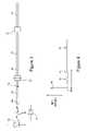
- FIG. 1is a schematic of the preferred embodiment of an OTDR in accordance with the invention.
- FIG. 2is a schematic of the preferred embodiment of the variable delay device of the OTDR of FIG. 1 .
- FIG. 3is a schematic of a light conduit having a damaged fiber optic cable, the light conduit being operatively connected to a laser pulse generator and to a sampling point.
- FIG. 1A schematic of the preferred embodiment of an OTDR in accordance with the invention is shown in FIG. 1 and is generally represented by the numeral 50 .
- the OTDR 50is operatively connected to an optical data transfer assembly 52 , and preferably comprises a variable delay device 54 , a sample-and-hold device 56 , an analog-to-digital converter 58 , and a microprocessor 60 .
- the OTDR 50is also operatively connected to a laser pulse generator 62 , which may form a portion of the OTDR or may be part of the optical data transfer assembly 52 to which the OTDR is attached.
- the digital comparator 66is operatively connected to the microprocessor 60 , the sample-and-hold device 56 , and the 10-bit counter 64 and is configured to trigger the sample-and-hold device to initiate sampling when time measured by the 10-bit counter matches a time delay instruction received from the microprocessor.
- the variable delay device 54is configured such that the microprocessor 60 can control the amount of time that passes between when a laser pulse is emitted by the laser pulse generator 62 , or from when a laser pulse passes a given point in the optical data transfer assembly 52 , and when the sample-and-hold device 56 begins sampling data.
- time delaycan be controlled by the variable delay device 54 to within a small fraction of a nanosecond of a target time delay.
- various types and configurations of time delay devicesare well known and that the time delay device 54 utilized in connection with the OTDR 50 of the preferred embodiment could have any other suitable configuration.
- the sample-and-hold device 56is operatively connected to a sampling point 67 of the optical data transfer assembly 52 in a manner such that data indicative of light intensity reaching the sampling point can be stored by the sample-and-hold device.
- the sample-and-hold device 56has a capture time of one nanosecond or less.
- the sample-and-hold device 56samples and stores data indicative of light intensity reaching the sampling point throughout the following nanosecond.
- the analog-to-digital converter 58is operatively connected to the sample-and-hold device 56 and to the microprocessor 60 and acts to convert and transmit the analog data recorded by sample-and-hold device 56 to the memory of the micro processor 60 in a digital format. No particular speed is required of the analog-to-digital converter 58 and an acquisition time of just a microsecond is suitable.
- the optical data transfer assembly 52 to which the OTDR is attachedcan be any type of optical data transfer assembly, such as an optical control system of an aircraft or an optical land-based communication network.
- the optical data transfer assemblycomprises a light conduit 68 for transmitting data via light.
- a light conduit 68includes one or more fiber optic cables 70 and may include connectors, air gaps, amplifiers, routers, or other items commonly found in optical data transfer assemblies.
- the laser pulse generator 62is preferably low wattage (approximately one milliwatt or less) and is operatively connected to the light conduit 68 in a manner such that the laser pulse generator 62 can emit laser pulses that travel along the light conduit. As mentioned above, the laser pulse generator 62 is also preferably operatively connected to the variable delay device 54 .
- FIGS. 3 and 4an example of a damaged light conduit 68 and the time domain response of a laser pulse emitted thereinto is shown schematically in FIGS. 3 and 4 respectively.
- the light conduit 68comprises several fiber optic cables 70 and several connectors 72 joining such cables.
- a laser pulse generator 62Also depicted is a laser pulse generator 62 , a sampling point 67 , and a damaged portion 74 of one of the fiber optic cables 70 . Assuming a laser pulse is generated by the laser pulse generator and travels along the light conduit (from left to right as shown in FIG. 3 ), the light intensity at the sampling point will vary with time as a result of reflections from the pulse, as shown in FIG. 4 .
- a first spike 76 of light intensitywill occur at the sampling point as the laser pulse reaches the sampling point on its way downstream.
- the light pulsecontinues downstream, it eventually encounters the damaged portion of light conduit and is at least partially reflected back upstream, while the remainder of the light pulse continues traveling downstream.
- This reflected portion of the laser pulsecreates a second light intensity spike when it ultimately reaches the sampling point.
- a portion of the laser pulseis reflected thereoff and travels back upstream along the light conduit, eventually reaching the sampling point. This creates yet additional third and fourth light intensity spikes 80 , 82 at the sampling point.
- the OTDRis preferably utilized in accordance with the flow-diagram shown in FIG. 5 to determine an approximate location of a damage portion of a light conduit to which the OTDR is operatively connected.
- the procedure or methodgenerally comprises the emission of a plurality of laser pulses and the compilation and analysis of data obtained from reflections of such laser pulses off of the damaged portion of the fiber optic cable at issue.
- the methodpreferably begins by activating the laser pulse generator to emit a laser pulse that travels in a first direction along the light conduit.
- the emission of the laser pulsepreferably also triggers the variable delay device to begin counting.
- the microprocessorinstructs the variable delay device to trigger the sample-and-hold device to commence recording data immediately following an initial time period from when the laser pulse was emitted.
- the time delay devicedetermines that such time period has passed, it activates the sample-and-hold device.
- the sample-and-hold deviceUpon activation, the sample-and-hold device records data indicative of light intensity reaching the sampling point over a nanosecond time period. After such sampling is completed, the analog-to-digital converter converts the data into digital format and transmits it to the microprocessor's memory or some other storage device.
- a second light pulseis emitted by the laser pulse generator, and the time delay device again begins counting.
- the microprocessorinstructs the variable delay device to trigger the sample-and-hold device to begin recording data immediately after the initial time period plus an incremental time period of one nanosecond has passed. Again, the data is converted and transmitted to the microprocessor's memory. These steps are repeated a number of times (represented as N in the flow-diagram), with the variable delay device being instructed to delay the triggering of the sample-and-hold device a nanosecond longer with each successive iteration.
- the number of iterations of the above-mentioned steps performed by the methodis dependent upon two main factors.
- the first factoris the desired accuracy of the approximation of the location of the damaged portion of the fiber optic cable.
- the second factoris the length of fiber optic cable being examined. For example, assuming that the light conduit is a single glass-fiber optic cable and it is desired to determine the location of any damaged portion thereof along 100 ft of its length to a resolution of three inches, the process will preferably include approximately 400 iterations (4 stages per foot times 100 feet). Additionally, the appropriate delay between stages, is dependent upon the speed that the light travels through the fiber optic cable and the desired resolution. Light travels in glass fibers at about 2 ⁇ 10 8 meters per second.
- the delay timeis determined strictly by the desired lineal resolution and is independent of the rate of data transfer being transmitted via the light conduit on other wavelength channels.
- the data transmitted to the microprocessorcan be analyzed by the microprocessor in an effort to determine at which iteration, and thus after what particular time delay, a reflection off of the damaged portion of the fiber optic cable reached the sampling point.
- the process of performing the iterations discussed aboveare repeated a number of times (represented as R in the flow-diagram) to improve the signal-to-noise ratio of the data.
- each sampled time instancewill result in data indicative of a composite signal that is “R” times as large as each individual sampled block of data.
- the signal-to-noise ratio of the measured responsewill improve by the square root of R and if, for example, all iterations are repeated 10,000 times, the signal-to-noise ratio is increased by a factor of 100.
- the microprocessorcompares the measured time domain response to a previously determined “healthy” time domain response to determine which, if any, reflections are new. In other words, even when undamaged, the time domain response will have spikes resulting from reflection off of various downstream components of the light conduits, such as the connectors. Thus, the comparison facilitates the identification of new spikes that may be the result of a damaged portion of fiber optic cable. After identifying a pertinent spike and the time delay associated therewith, it follows then that the microprocessor can interpolate an approximate distance to the damaged portion that created the spike.
- prior art OTDRsare capable of achieving the same ultimate result, i.e. the determination of an approximate distance to a damaged portion of a fiber optic cable
- the OTDR of the preferred embodiment and the method described hereinhas significant advantages thereover.
- prior art OTDR devices capable of similar precisionrequire many more components and/or much more expensive components.
- prior art deviceshave rather large power consumptions.
- the components associated with the OTDR of the preferred embodiment of the inventionare very inexpensive and consume minimal power.
- the circuit of the OTDR of the preferred embodimentimposes no particular timing constraints on the analog-to-digital converter, memory storage device, or microprocessor.
- an analog-to-digital converterwith, say, a one microsecond acquisition time would be suitable. Note that, if this is in fact the analog-to-digital acquisition time, and if the required number of samples along the length of the light conduit were 400, and if the required number of measurement repetitions to attain sufficient signal-to-noise ratios is 10,000, then the entire method can still be performed in only 4 seconds (10,000*400*1 ⁇ sec). This is a reasonable measurement of time, considering a channel (wavelength) can be devoted solely to this measurement.
- OTDRsin accordance with this invention allows such OTDRs to be installed as an integral part of an optical data transfer assembly where, if desired, they can be continually utilized to monitor the health of such optical data transfer assembly.
- Thisis extremely beneficial for military aircraft having fiber optic control systems, be they flight, weapon, or other types of control systems. Such aircraft are frequently operated from locations where prior art external OTDRs are unavailble.
- a baseline or healthy OTDR time domain reflection responsemust be known in each case in order to compare it to the current OTDR signature. With prior art OTDRs, this would require keeping all OTDR signatures in a database and updated such database whenever maintenance is done on a cable assembly.
- a “damaged portion” of a fiber optic cablecould be, but is certainly not limited to, a disconnected coupler, a complete sever of the cable, or merely a scratch extending through the outer glass cladding of the fiber optic cable and just slightly into its inner glass core that doesn't even appreciably diminish data transfer.
- the delay devicecould be operatively connected to the laser pulse generator through the microprocessor, and the microprocessor configured to trigger both the delay device and the laser pulse generator simultaneously.
- the delay devicecould be operatively connected to the laser pulse generator through the microprocessor, and the microprocessor configured to trigger both the delay device and the laser pulse generator simultaneously.
Landscapes
- Physics & Mathematics (AREA)
- Optics & Photonics (AREA)
- Chemical & Material Sciences (AREA)
- Analytical Chemistry (AREA)
- General Physics & Mathematics (AREA)
- Optical Radar Systems And Details Thereof (AREA)
- Investigating Or Analysing Materials By Optical Means (AREA)
Abstract
Description
Claims (13)
Priority Applications (1)
| Application Number | Priority Date | Filing Date | Title |
|---|---|---|---|
| US10/722,688US7095493B2 (en) | 2003-11-24 | 2003-11-24 | Optical time domain reflectometer and method of using the same |
Applications Claiming Priority (1)
| Application Number | Priority Date | Filing Date | Title |
|---|---|---|---|
| US10/722,688US7095493B2 (en) | 2003-11-24 | 2003-11-24 | Optical time domain reflectometer and method of using the same |
Publications (2)
| Publication Number | Publication Date |
|---|---|
| US20050110979A1 US20050110979A1 (en) | 2005-05-26 |
| US7095493B2true US7095493B2 (en) | 2006-08-22 |
Family
ID=34592041
Family Applications (1)
| Application Number | Title | Priority Date | Filing Date |
|---|---|---|---|
| US10/722,688Expired - Fee RelatedUS7095493B2 (en) | 2003-11-24 | 2003-11-24 | Optical time domain reflectometer and method of using the same |
Country Status (1)
| Country | Link |
|---|---|
| US (1) | US7095493B2 (en) |
Cited By (53)
| Publication number | Priority date | Publication date | Assignee | Title |
|---|---|---|---|---|
| US20060232765A1 (en)* | 2004-05-13 | 2006-10-19 | Harres Daniel N | Mixer-based time domain reflectometer and method |
| US20080094615A1 (en)* | 2006-10-23 | 2008-04-24 | Harres Daniel N | Optical phase domain reflectometer |
| US20090319116A1 (en)* | 2008-06-18 | 2009-12-24 | Keller Kirby J | Systems and method for collecting data in a vehicle |
| US9286673B2 (en) | 2012-10-05 | 2016-03-15 | Volcano Corporation | Systems for correcting distortions in a medical image and methods of use thereof |
| US9292918B2 (en) | 2012-10-05 | 2016-03-22 | Volcano Corporation | Methods and systems for transforming luminal images |
| US9301687B2 (en) | 2013-03-13 | 2016-04-05 | Volcano Corporation | System and method for OCT depth calibration |
| US9307926B2 (en) | 2012-10-05 | 2016-04-12 | Volcano Corporation | Automatic stent detection |
| US9324141B2 (en) | 2012-10-05 | 2016-04-26 | Volcano Corporation | Removal of A-scan streaking artifact |
| US9360630B2 (en) | 2011-08-31 | 2016-06-07 | Volcano Corporation | Optical-electrical rotary joint and methods of use |
| US9367965B2 (en) | 2012-10-05 | 2016-06-14 | Volcano Corporation | Systems and methods for generating images of tissue |
| US9383263B2 (en) | 2012-12-21 | 2016-07-05 | Volcano Corporation | Systems and methods for narrowing a wavelength emission of light |
| US9478940B2 (en) | 2012-10-05 | 2016-10-25 | Volcano Corporation | Systems and methods for amplifying light |
| US9486143B2 (en) | 2012-12-21 | 2016-11-08 | Volcano Corporation | Intravascular forward imaging device |
| US9596993B2 (en) | 2007-07-12 | 2017-03-21 | Volcano Corporation | Automatic calibration systems and methods of use |
| US9612105B2 (en) | 2012-12-21 | 2017-04-04 | Volcano Corporation | Polarization sensitive optical coherence tomography system |
| US9622706B2 (en) | 2007-07-12 | 2017-04-18 | Volcano Corporation | Catheter for in vivo imaging |
| US9709379B2 (en) | 2012-12-20 | 2017-07-18 | Volcano Corporation | Optical coherence tomography system that is reconfigurable between different imaging modes |
| US9730613B2 (en) | 2012-12-20 | 2017-08-15 | Volcano Corporation | Locating intravascular images |
| US9770172B2 (en) | 2013-03-07 | 2017-09-26 | Volcano Corporation | Multimodal segmentation in intravascular images |
| US9858668B2 (en) | 2012-10-05 | 2018-01-02 | Volcano Corporation | Guidewire artifact removal in images |
| US9867530B2 (en) | 2006-08-14 | 2018-01-16 | Volcano Corporation | Telescopic side port catheter device with imaging system and method for accessing side branch occlusions |
| US9923630B2 (en) | 2016-04-20 | 2018-03-20 | Lockheed Martin Corporation | Analyzing optical networks |
| US10058284B2 (en) | 2012-12-21 | 2018-08-28 | Volcano Corporation | Simultaneous imaging, monitoring, and therapy |
| US10070827B2 (en) | 2012-10-05 | 2018-09-11 | Volcano Corporation | Automatic image playback |
| US10166003B2 (en) | 2012-12-21 | 2019-01-01 | Volcano Corporation | Ultrasound imaging with variable line density |
| US10191220B2 (en) | 2012-12-21 | 2019-01-29 | Volcano Corporation | Power-efficient optical circuit |
| US10219887B2 (en) | 2013-03-14 | 2019-03-05 | Volcano Corporation | Filters with echogenic characteristics |
| US10219780B2 (en) | 2007-07-12 | 2019-03-05 | Volcano Corporation | OCT-IVUS catheter for concurrent luminal imaging |
| US10226597B2 (en) | 2013-03-07 | 2019-03-12 | Volcano Corporation | Guidewire with centering mechanism |
| US10230459B2 (en)* | 2017-02-14 | 2019-03-12 | The Boeing Company | System and method for optical time-domain reflectometry and design data wire testing |
| US10238367B2 (en) | 2012-12-13 | 2019-03-26 | Volcano Corporation | Devices, systems, and methods for targeted cannulation |
| US10292677B2 (en) | 2013-03-14 | 2019-05-21 | Volcano Corporation | Endoluminal filter having enhanced echogenic properties |
| US10305587B2 (en) | 2014-05-09 | 2019-05-28 | Sikorsky Aircraft Corporation | Method and apparatus for condition based maintenance of fiber networks on vehicles |
| US10332228B2 (en) | 2012-12-21 | 2019-06-25 | Volcano Corporation | System and method for graphical processing of medical data |
| US10413317B2 (en) | 2012-12-21 | 2019-09-17 | Volcano Corporation | System and method for catheter steering and operation |
| US10420530B2 (en) | 2012-12-21 | 2019-09-24 | Volcano Corporation | System and method for multipath processing of image signals |
| US10426590B2 (en) | 2013-03-14 | 2019-10-01 | Volcano Corporation | Filters with echogenic characteristics |
| US10568586B2 (en) | 2012-10-05 | 2020-02-25 | Volcano Corporation | Systems for indicating parameters in an imaging data set and methods of use |
| US10595820B2 (en) | 2012-12-20 | 2020-03-24 | Philips Image Guided Therapy Corporation | Smooth transition catheters |
| US10638939B2 (en) | 2013-03-12 | 2020-05-05 | Philips Image Guided Therapy Corporation | Systems and methods for diagnosing coronary microvascular disease |
| US10724082B2 (en) | 2012-10-22 | 2020-07-28 | Bio-Rad Laboratories, Inc. | Methods for analyzing DNA |
| US10758207B2 (en) | 2013-03-13 | 2020-09-01 | Philips Image Guided Therapy Corporation | Systems and methods for producing an image from a rotational intravascular ultrasound device |
| US10939826B2 (en) | 2012-12-20 | 2021-03-09 | Philips Image Guided Therapy Corporation | Aspirating and removing biological material |
| US10942022B2 (en) | 2012-12-20 | 2021-03-09 | Philips Image Guided Therapy Corporation | Manual calibration of imaging system |
| US10993694B2 (en) | 2012-12-21 | 2021-05-04 | Philips Image Guided Therapy Corporation | Rotational ultrasound imaging catheter with extended catheter body telescope |
| US11026591B2 (en) | 2013-03-13 | 2021-06-08 | Philips Image Guided Therapy Corporation | Intravascular pressure sensor calibration |
| US11040140B2 (en) | 2010-12-31 | 2021-06-22 | Philips Image Guided Therapy Corporation | Deep vein thrombosis therapeutic methods |
| US11141063B2 (en) | 2010-12-23 | 2021-10-12 | Philips Image Guided Therapy Corporation | Integrated system architectures and methods of use |
| US11154313B2 (en) | 2013-03-12 | 2021-10-26 | The Volcano Corporation | Vibrating guidewire torquer and methods of use |
| US11272845B2 (en) | 2012-10-05 | 2022-03-15 | Philips Image Guided Therapy Corporation | System and method for instant and automatic border detection |
| US11406498B2 (en) | 2012-12-20 | 2022-08-09 | Philips Image Guided Therapy Corporation | Implant delivery system and implants |
| US12201477B2 (en) | 2012-10-05 | 2025-01-21 | Philips Image Guided Therapy Corporation | Methods and systems for establishing parameters for three-dimensional imaging |
| US12343198B2 (en) | 2013-03-14 | 2025-07-01 | Philips Image Guided Therapy Corporation | Delivery catheter having imaging capabilities |
Families Citing this family (10)
| Publication number | Priority date | Publication date | Assignee | Title |
|---|---|---|---|---|
| US7433596B2 (en)* | 2005-12-23 | 2008-10-07 | The Boeing Corporation | Bi-directional, full-duplex, one-wire communications link for use in fiber optic transceivers |
| US7639001B2 (en)* | 2006-01-17 | 2009-12-29 | The Boeing Company | Built-in test for high speed electrical networks |
| US7573311B2 (en)* | 2007-11-01 | 2009-08-11 | The Boeing Company | Programmable high-resolution phase delay |
| KR20090077483A (en)* | 2008-01-11 | 2009-07-15 | 삼성디지털이미징 주식회사 | Digital photographing device and control method thereof |
| US8213002B2 (en)* | 2009-03-04 | 2012-07-03 | Fluke Corporation | PON tester |
| CN101917226B (en)* | 2010-08-23 | 2016-03-02 | 中兴通讯股份有限公司 | A kind of method and optical line terminal carrying out fiber fault diagnosis in EPON |
| DE102011106783A1 (en)* | 2011-07-06 | 2013-01-10 | Eads Deutschland Gmbh | Optical data transmission system |
| US9485016B2 (en)* | 2013-09-20 | 2016-11-01 | Fluke Corporation | Hands-free optical fiber testing using optical loss test instrument |
| EP3249375A1 (en) | 2016-05-27 | 2017-11-29 | Xieon Networks S.à r.l. | Otdr with increased precision and reduced dead zone using superposition of pulses with varying clock signal delay |
| CN113340571B (en)* | 2021-05-29 | 2023-11-10 | 南京航空航天大学 | Optical delay measurement method and device based on light vector analysis |
Citations (3)
| Publication number | Priority date | Publication date | Assignee | Title |
|---|---|---|---|---|
| US5467942A (en)* | 1991-08-28 | 1995-11-21 | The Boeing Company | Temperature sensing optical system |
| US6614512B1 (en)* | 1999-09-06 | 2003-09-02 | Anritsu Corporation | System for measuring wavelength dispersion of optical fiber |
| US6771361B2 (en)* | 2002-02-28 | 2004-08-03 | Kyusyo Ando Electric Company Limited | Optical pulse testing device |
- 2003
- 2003-11-24USUS10/722,688patent/US7095493B2/ennot_activeExpired - Fee Related
Patent Citations (3)
| Publication number | Priority date | Publication date | Assignee | Title |
|---|---|---|---|---|
| US5467942A (en)* | 1991-08-28 | 1995-11-21 | The Boeing Company | Temperature sensing optical system |
| US6614512B1 (en)* | 1999-09-06 | 2003-09-02 | Anritsu Corporation | System for measuring wavelength dispersion of optical fiber |
| US6771361B2 (en)* | 2002-02-28 | 2004-08-03 | Kyusyo Ando Electric Company Limited | Optical pulse testing device |
Cited By (68)
| Publication number | Priority date | Publication date | Assignee | Title |
|---|---|---|---|---|
| US8194239B2 (en) | 2004-05-13 | 2012-06-05 | The Boeing Company | Mixer-based time domain reflectometer and method |
| US7667830B2 (en) | 2004-05-13 | 2010-02-23 | The Boeing Company | Mixer-based time domain reflectometer and method |
| US20100079746A1 (en)* | 2004-05-13 | 2010-04-01 | Harres Daniel N | Mixer-based time domain reflectometer and method |
| US20060232765A1 (en)* | 2004-05-13 | 2006-10-19 | Harres Daniel N | Mixer-based time domain reflectometer and method |
| US9867530B2 (en) | 2006-08-14 | 2018-01-16 | Volcano Corporation | Telescopic side port catheter device with imaging system and method for accessing side branch occlusions |
| US20080094615A1 (en)* | 2006-10-23 | 2008-04-24 | Harres Daniel N | Optical phase domain reflectometer |
| US8045143B2 (en) | 2006-10-23 | 2011-10-25 | The Boeing Company | Optical phase domain reflectometer |
| US10219780B2 (en) | 2007-07-12 | 2019-03-05 | Volcano Corporation | OCT-IVUS catheter for concurrent luminal imaging |
| US9596993B2 (en) | 2007-07-12 | 2017-03-21 | Volcano Corporation | Automatic calibration systems and methods of use |
| US11350906B2 (en) | 2007-07-12 | 2022-06-07 | Philips Image Guided Therapy Corporation | OCT-IVUS catheter for concurrent luminal imaging |
| US9622706B2 (en) | 2007-07-12 | 2017-04-18 | Volcano Corporation | Catheter for in vivo imaging |
| US8116940B2 (en) | 2008-06-18 | 2012-02-14 | The Boeing Company | Systems and method for collecting data in a vehicle |
| US20090319116A1 (en)* | 2008-06-18 | 2009-12-24 | Keller Kirby J | Systems and method for collecting data in a vehicle |
| US11141063B2 (en) | 2010-12-23 | 2021-10-12 | Philips Image Guided Therapy Corporation | Integrated system architectures and methods of use |
| US11040140B2 (en) | 2010-12-31 | 2021-06-22 | Philips Image Guided Therapy Corporation | Deep vein thrombosis therapeutic methods |
| US9360630B2 (en) | 2011-08-31 | 2016-06-07 | Volcano Corporation | Optical-electrical rotary joint and methods of use |
| US9292918B2 (en) | 2012-10-05 | 2016-03-22 | Volcano Corporation | Methods and systems for transforming luminal images |
| US10070827B2 (en) | 2012-10-05 | 2018-09-11 | Volcano Corporation | Automatic image playback |
| US9478940B2 (en) | 2012-10-05 | 2016-10-25 | Volcano Corporation | Systems and methods for amplifying light |
| US11864870B2 (en) | 2012-10-05 | 2024-01-09 | Philips Image Guided Therapy Corporation | System and method for instant and automatic border detection |
| US9324141B2 (en) | 2012-10-05 | 2016-04-26 | Volcano Corporation | Removal of A-scan streaking artifact |
| US9286673B2 (en) | 2012-10-05 | 2016-03-15 | Volcano Corporation | Systems for correcting distortions in a medical image and methods of use thereof |
| US12201477B2 (en) | 2012-10-05 | 2025-01-21 | Philips Image Guided Therapy Corporation | Methods and systems for establishing parameters for three-dimensional imaging |
| US11510632B2 (en) | 2012-10-05 | 2022-11-29 | Philips Image Guided Therapy Corporation | Systems for indicating parameters in an imaging data set and methods of use |
| US9858668B2 (en) | 2012-10-05 | 2018-01-02 | Volcano Corporation | Guidewire artifact removal in images |
| US9307926B2 (en) | 2012-10-05 | 2016-04-12 | Volcano Corporation | Automatic stent detection |
| US11890117B2 (en) | 2012-10-05 | 2024-02-06 | Philips Image Guided Therapy Corporation | Systems for indicating parameters in an imaging data set and methods of use |
| US10568586B2 (en) | 2012-10-05 | 2020-02-25 | Volcano Corporation | Systems for indicating parameters in an imaging data set and methods of use |
| US9367965B2 (en) | 2012-10-05 | 2016-06-14 | Volcano Corporation | Systems and methods for generating images of tissue |
| US11272845B2 (en) | 2012-10-05 | 2022-03-15 | Philips Image Guided Therapy Corporation | System and method for instant and automatic border detection |
| US10724082B2 (en) | 2012-10-22 | 2020-07-28 | Bio-Rad Laboratories, Inc. | Methods for analyzing DNA |
| US10238367B2 (en) | 2012-12-13 | 2019-03-26 | Volcano Corporation | Devices, systems, and methods for targeted cannulation |
| US9730613B2 (en) | 2012-12-20 | 2017-08-15 | Volcano Corporation | Locating intravascular images |
| US11141131B2 (en) | 2012-12-20 | 2021-10-12 | Philips Image Guided Therapy Corporation | Smooth transition catheters |
| US11406498B2 (en) | 2012-12-20 | 2022-08-09 | Philips Image Guided Therapy Corporation | Implant delivery system and implants |
| US11892289B2 (en) | 2012-12-20 | 2024-02-06 | Philips Image Guided Therapy Corporation | Manual calibration of imaging system |
| US9709379B2 (en) | 2012-12-20 | 2017-07-18 | Volcano Corporation | Optical coherence tomography system that is reconfigurable between different imaging modes |
| US10942022B2 (en) | 2012-12-20 | 2021-03-09 | Philips Image Guided Therapy Corporation | Manual calibration of imaging system |
| US10939826B2 (en) | 2012-12-20 | 2021-03-09 | Philips Image Guided Therapy Corporation | Aspirating and removing biological material |
| US10595820B2 (en) | 2012-12-20 | 2020-03-24 | Philips Image Guided Therapy Corporation | Smooth transition catheters |
| US10993694B2 (en) | 2012-12-21 | 2021-05-04 | Philips Image Guided Therapy Corporation | Rotational ultrasound imaging catheter with extended catheter body telescope |
| US9486143B2 (en) | 2012-12-21 | 2016-11-08 | Volcano Corporation | Intravascular forward imaging device |
| US10420530B2 (en) | 2012-12-21 | 2019-09-24 | Volcano Corporation | System and method for multipath processing of image signals |
| US10413317B2 (en) | 2012-12-21 | 2019-09-17 | Volcano Corporation | System and method for catheter steering and operation |
| US11786213B2 (en) | 2012-12-21 | 2023-10-17 | Philips Image Guided Therapy Corporation | System and method for multipath processing of image signals |
| US10332228B2 (en) | 2012-12-21 | 2019-06-25 | Volcano Corporation | System and method for graphical processing of medical data |
| US10058284B2 (en) | 2012-12-21 | 2018-08-28 | Volcano Corporation | Simultaneous imaging, monitoring, and therapy |
| US10166003B2 (en) | 2012-12-21 | 2019-01-01 | Volcano Corporation | Ultrasound imaging with variable line density |
| US9383263B2 (en) | 2012-12-21 | 2016-07-05 | Volcano Corporation | Systems and methods for narrowing a wavelength emission of light |
| US11253225B2 (en) | 2012-12-21 | 2022-02-22 | Philips Image Guided Therapy Corporation | System and method for multipath processing of image signals |
| US9612105B2 (en) | 2012-12-21 | 2017-04-04 | Volcano Corporation | Polarization sensitive optical coherence tomography system |
| US10191220B2 (en) | 2012-12-21 | 2019-01-29 | Volcano Corporation | Power-efficient optical circuit |
| US10226597B2 (en) | 2013-03-07 | 2019-03-12 | Volcano Corporation | Guidewire with centering mechanism |
| US9770172B2 (en) | 2013-03-07 | 2017-09-26 | Volcano Corporation | Multimodal segmentation in intravascular images |
| US11154313B2 (en) | 2013-03-12 | 2021-10-26 | The Volcano Corporation | Vibrating guidewire torquer and methods of use |
| US12350018B2 (en) | 2013-03-12 | 2025-07-08 | Philips Image Guided Therapy Corporation | Systems and methods for diagnosing coronary microvascular disease |
| US10638939B2 (en) | 2013-03-12 | 2020-05-05 | Philips Image Guided Therapy Corporation | Systems and methods for diagnosing coronary microvascular disease |
| US9301687B2 (en) | 2013-03-13 | 2016-04-05 | Volcano Corporation | System and method for OCT depth calibration |
| US11026591B2 (en) | 2013-03-13 | 2021-06-08 | Philips Image Guided Therapy Corporation | Intravascular pressure sensor calibration |
| US10758207B2 (en) | 2013-03-13 | 2020-09-01 | Philips Image Guided Therapy Corporation | Systems and methods for producing an image from a rotational intravascular ultrasound device |
| US10219887B2 (en) | 2013-03-14 | 2019-03-05 | Volcano Corporation | Filters with echogenic characteristics |
| US10426590B2 (en) | 2013-03-14 | 2019-10-01 | Volcano Corporation | Filters with echogenic characteristics |
| US12343198B2 (en) | 2013-03-14 | 2025-07-01 | Philips Image Guided Therapy Corporation | Delivery catheter having imaging capabilities |
| US10292677B2 (en) | 2013-03-14 | 2019-05-21 | Volcano Corporation | Endoluminal filter having enhanced echogenic properties |
| US10305587B2 (en) | 2014-05-09 | 2019-05-28 | Sikorsky Aircraft Corporation | Method and apparatus for condition based maintenance of fiber networks on vehicles |
| US9923630B2 (en) | 2016-04-20 | 2018-03-20 | Lockheed Martin Corporation | Analyzing optical networks |
| US10230459B2 (en)* | 2017-02-14 | 2019-03-12 | The Boeing Company | System and method for optical time-domain reflectometry and design data wire testing |
| US10841004B2 (en) | 2017-02-14 | 2020-11-17 | The Boeing Company | System and method for optical time-domain reflectometry and design data wire testing |
Also Published As
| Publication number | Publication date |
|---|---|
| US20050110979A1 (en) | 2005-05-26 |
Similar Documents
| Publication | Publication Date | Title |
|---|---|---|
| US7095493B2 (en) | Optical time domain reflectometer and method of using the same | |
| US10935418B2 (en) | High-rate fiber-optical distributed acoustic sensing | |
| AU617913B2 (en) | Loss detection | |
| US8502964B2 (en) | Chaotic optical time domain reflectometer method and apparatus | |
| US9134197B2 (en) | Bi-directional multi-pulsewidth optical time-domain reflectometer | |
| US5708500A (en) | Multimode optical time domain reflectometer having improved resolution | |
| US20140146312A1 (en) | Optical reflectometer with loss and/or reflectance profile view | |
| US20080285916A1 (en) | All-Fiber Architecture for an Embedded Flight Sensor for Aeropropulsion Applications | |
| US20130208264A1 (en) | Integrated optical time domain reflectometer | |
| CN102577179B (en) | The method of optical time domain reflectometer and acquisition test signal thereof | |
| CN104040598A (en) | Disturbance sensor for interference-type optical fiber and sensing method thereof | |
| US5500730A (en) | Method and apparatus for determining the distance to a reflective event | |
| CN101794506B (en) | Method and device for data calibration in distributed optical fiber temperature sensing system | |
| CN102540168A (en) | Outdoor on-line simulative detection method and device for distance measuring capacity of infrared phase distance measurer | |
| US9909951B2 (en) | Apparatus and method for characterization of FBG rellector array | |
| GB1560124A (en) | Optical fibre cable testing | |
| CN1113490C (en) | Optical module for light-time domain reflectometer with wide dynamic range | |
| CN1275397C (en) | Optical signal transmission delay measuring method in transmission chain and apparatus thereof | |
| EP0499171A1 (en) | Fresnel reflections locating system along an optical fibre | |
| US6912046B2 (en) | Instrument measuring chromatic dispersion in optical fibers | |
| JPH0712655A (en) | Measuring system | |
| CN201628593U (en) | Data correction device of distributed optical fiber temperature sensing system | |
| US5465143A (en) | ADP switch and adjustable data acquisition window | |
| CN112161950A (en) | Methane concentration distributed optical fiber detection system | |
| EP4273509A1 (en) | Device and method for distributed sensing, preferably in a star network |
Legal Events
| Date | Code | Title | Description |
|---|---|---|---|
| AS | Assignment | Owner name:THE BOEING COMPANY, ILLINOIS Free format text:ASSIGNMENT OF ASSIGNORS INTEREST;ASSIGNOR:HARRES, DANIEL N.;REEL/FRAME:014755/0210 Effective date:20031121 | |
| FEPP | Fee payment procedure | Free format text:PAYOR NUMBER ASSIGNED (ORIGINAL EVENT CODE: ASPN); ENTITY STATUS OF PATENT OWNER: LARGE ENTITY | |
| FPAY | Fee payment | Year of fee payment:4 | |
| CC | Certificate of correction | ||
| FPAY | Fee payment | Year of fee payment:8 | |
| AS | Assignment | Owner name:DEPARTMENT OF THE NAVY, MARYLAND Free format text:CONFIRMATORY LICENSE;ASSIGNOR:BOEING COMPANY;REEL/FRAME:035647/0257 Effective date:20141217 | |
| FEPP | Fee payment procedure | Free format text:MAINTENANCE FEE REMINDER MAILED (ORIGINAL EVENT CODE: REM.) | |
| LAPS | Lapse for failure to pay maintenance fees | Free format text:PATENT EXPIRED FOR FAILURE TO PAY MAINTENANCE FEES (ORIGINAL EVENT CODE: EXP.); ENTITY STATUS OF PATENT OWNER: LARGE ENTITY | |
| STCH | Information on status: patent discontinuation | Free format text:PATENT EXPIRED DUE TO NONPAYMENT OF MAINTENANCE FEES UNDER 37 CFR 1.362 | |
| FP | Lapsed due to failure to pay maintenance fee | Effective date:20180822 |