US7094251B2 - Apparatus and method for securing a suture - Google Patents
Apparatus and method for securing a sutureDownload PDFInfo
- Publication number
- US7094251B2 US7094251B2US10/228,855US22885502AUS7094251B2US 7094251 B2US7094251 B2US 7094251B2US 22885502 AUS22885502 AUS 22885502AUS 7094251 B2US7094251 B2US 7094251B2
- Authority
- US
- United States
- Prior art keywords
- retainer
- suture
- sections
- projections
- section
- Prior art date
- Legal status (The legal status is an assumption and is not a legal conclusion. Google has not performed a legal analysis and makes no representation as to the accuracy of the status listed.)
- Expired - Lifetime, expires
Links
- 238000000034methodMethods0.000titleclaimsdescription164
- 239000000463materialSubstances0.000claimsdescription82
- 230000033001locomotionEffects0.000claimsdescription37
- 230000003247decreasing effectEffects0.000claimsdescription18
- 230000000694effectsEffects0.000claimsdescription9
- 210000001519tissueAnatomy0.000description132
- 230000005540biological transmissionEffects0.000description51
- 238000010276constructionMethods0.000description30
- 230000007246mechanismEffects0.000description26
- 230000007704transitionEffects0.000description18
- 238000001356surgical procedureMethods0.000description16
- 238000003384imaging methodMethods0.000description14
- 239000012141concentrateSubstances0.000description12
- 230000009471actionEffects0.000description7
- 238000003780insertionMethods0.000description7
- 230000037431insertionEffects0.000description7
- 229920003023plasticPolymers0.000description7
- 229920000642polymerPolymers0.000description6
- 229920001577copolymerPolymers0.000description4
- 238000010438heat treatmentMethods0.000description4
- 229920001432poly(L-lactide)Polymers0.000description4
- 230000003313weakening effectEffects0.000description4
- 230000015572biosynthetic processEffects0.000description3
- JVTAAEKCZFNVCJ-REOHCLBHSA-NL-lactic acidChemical compoundC[C@H](O)C(O)=OJVTAAEKCZFNVCJ-REOHCLBHSA-N0.000description2
- 210000001124body fluidAnatomy0.000description2
- 239000010839body fluidSubstances0.000description2
- 210000000988bone and boneAnatomy0.000description2
- 230000009969flowable effectEffects0.000description2
- 238000002844meltingMethods0.000description2
- 230000008018meltingEffects0.000description2
- 239000002184metalSubstances0.000description2
- 238000002324minimally invasive surgeryMethods0.000description2
- 230000003044adaptive effectEffects0.000description1
- 238000013459approachMethods0.000description1
- 238000012976endoscopic surgical procedureMethods0.000description1
- 239000000835fiberSubstances0.000description1
- 230000001771impaired effectEffects0.000description1
- 230000003993interactionEffects0.000description1
- 239000007788liquidSubstances0.000description1
- 238000002595magnetic resonance imagingMethods0.000description1
- 238000012978minimally invasive surgical procedureMethods0.000description1
- 230000003287optical effectEffects0.000description1
- 210000004872soft tissueAnatomy0.000description1
- 238000003466weldingMethods0.000description1
Images


Classifications
- A—HUMAN NECESSITIES
- A61—MEDICAL OR VETERINARY SCIENCE; HYGIENE
- A61B—DIAGNOSIS; SURGERY; IDENTIFICATION
- A61B17/00—Surgical instruments, devices or methods
- A61B17/04—Surgical instruments, devices or methods for suturing wounds; Holders or packages for needles or suture materials
- A61B17/0487—Suture clamps, clips or locks, e.g. for replacing suture knots; Instruments for applying or removing suture clamps, clips or locks
- A—HUMAN NECESSITIES
- A61—MEDICAL OR VETERINARY SCIENCE; HYGIENE
- A61B—DIAGNOSIS; SURGERY; IDENTIFICATION
- A61B17/00—Surgical instruments, devices or methods
- A61B17/04—Surgical instruments, devices or methods for suturing wounds; Holders or packages for needles or suture materials
- A61B17/0401—Suture anchors, buttons or pledgets, i.e. means for attaching sutures to bone, cartilage or soft tissue; Instruments for applying or removing suture anchors
- A61B2017/0446—Means for attaching and blocking the suture in the suture anchor
- A61B2017/0448—Additional elements on or within the anchor
- A61B2017/045—Additional elements on or within the anchor snug fit within the anchor
- A—HUMAN NECESSITIES
- A61—MEDICAL OR VETERINARY SCIENCE; HYGIENE
- A61B—DIAGNOSIS; SURGERY; IDENTIFICATION
- A61B17/00—Surgical instruments, devices or methods
- A61B17/04—Surgical instruments, devices or methods for suturing wounds; Holders or packages for needles or suture materials
- A61B17/0401—Suture anchors, buttons or pledgets, i.e. means for attaching sutures to bone, cartilage or soft tissue; Instruments for applying or removing suture anchors
- A61B2017/0446—Means for attaching and blocking the suture in the suture anchor
- A61B2017/0459—Multiple holes in the anchor through which the suture extends and locking the suture when tension is applied
- A—HUMAN NECESSITIES
- A61—MEDICAL OR VETERINARY SCIENCE; HYGIENE
- A61B—DIAGNOSIS; SURGERY; IDENTIFICATION
- A61B17/00—Surgical instruments, devices or methods
- A61B17/04—Surgical instruments, devices or methods for suturing wounds; Holders or packages for needles or suture materials
- A61B17/0401—Suture anchors, buttons or pledgets, i.e. means for attaching sutures to bone, cartilage or soft tissue; Instruments for applying or removing suture anchors
- A61B2017/0464—Suture anchors, buttons or pledgets, i.e. means for attaching sutures to bone, cartilage or soft tissue; Instruments for applying or removing suture anchors for soft tissue
- A—HUMAN NECESSITIES
- A61—MEDICAL OR VETERINARY SCIENCE; HYGIENE
- A61B—DIAGNOSIS; SURGERY; IDENTIFICATION
- A61B17/00—Surgical instruments, devices or methods
- A61B17/04—Surgical instruments, devices or methods for suturing wounds; Holders or packages for needles or suture materials
- A61B17/0487—Suture clamps, clips or locks, e.g. for replacing suture knots; Instruments for applying or removing suture clamps, clips or locks
- A61B2017/0488—Instruments for applying suture clamps, clips or locks
- A—HUMAN NECESSITIES
- A61—MEDICAL OR VETERINARY SCIENCE; HYGIENE
- A61B—DIAGNOSIS; SURGERY; IDENTIFICATION
- A61B17/00—Surgical instruments, devices or methods
- A61B17/04—Surgical instruments, devices or methods for suturing wounds; Holders or packages for needles or suture materials
- A61B17/06—Needles ; Sutures; Needle-suture combinations; Holders or packages for needles or suture materials
- A61B17/06166—Sutures
- A61B2017/0619—Sutures thermoplastic, e.g. for bonding, welding, fusing or cutting the suture by melting it
- Y—GENERAL TAGGING OF NEW TECHNOLOGICAL DEVELOPMENTS; GENERAL TAGGING OF CROSS-SECTIONAL TECHNOLOGIES SPANNING OVER SEVERAL SECTIONS OF THE IPC; TECHNICAL SUBJECTS COVERED BY FORMER USPC CROSS-REFERENCE ART COLLECTIONS [XRACs] AND DIGESTS
- Y10—TECHNICAL SUBJECTS COVERED BY FORMER USPC
- Y10T—TECHNICAL SUBJECTS COVERED BY FORMER US CLASSIFICATION
- Y10T24/00—Buckles, buttons, clasps, etc.
- Y10T24/39—Cord and rope holders
Definitions
- the present inventionrelates to a new and improved apparatus and method which are used to secure a suture relative to body tissue.
- a retainermay be connected with a suture by applying energy to the retainer. The energy effects a bonding of one portion of the retainer to another portion of the retainer. It has previously been suggested that a retainer could be connected with a suture in the manner disclosed in Japanese laid-open Patent Application No. 8-140,982 and in U.S. Pat. Nos. 6,010,525; 6,174,324; and 6,368,343.
- the present inventionrelates to a new and improved apparatus and method for use in securing a suture.
- the sutureis positioned relative to sections of an improved retainer.
- the sections of the retainerare interconnected when the retainer has been positioned relative to a patient's body tissue.
- the sections of the retainermay be bonded together by the application of energy to the retainer by an improved applicator assembly.
- the improved retainermay have one or more projections which engage one or more recesses to position the sections of the retainer relative to each other.
- An interference fitmay be provided between one or more projections and one or more recesses to hold the sections of the retainer in a desired spatial relationship.
- the projectionsmay have surfaces which at least partially define one or more passages and guide movement of one or more portions of the suture relative to the retainer.
- the surfaces on the projectionsmay function to position the suture relative to the retainer.
- the improved applicator assemblymay be used to apply energy to the retainer.
- Energy applied to the retainermay effect bonding of end portions of the projections to bottom portions of recesses in the retainer.
- the end portions of the projectionsmay function as energy directors which concentrate energy.
- one or more loopsmay be formed in the suture around one or more of the projections.
- the applicator assemblymay grip the retainer with a predetermined force. While the applicator assembly grips the retainer, the applicator assembly may be utilized to slide the retainer along the suture to position the retainer relative to body tissue. While the applicator assembly is gripping the retainer, the applicator assembly may apply energy to the retainer to effect bonding of sections of the retainer together. The applicator assembly may be used to move the retainer into a cannula to engage tissue in a patient's body.
- the present inventionincludes a plurality of different features which may be utilized in combination with each other or separately.
- the various features of the inventionmay be used in combination with features of the prior art.
- the improved retainermay be used with the improved applicator assembly or with a prior art applicator assembly.
- the improved applicator assemblymay be used with the improved retainer or a prior art retainer.
- the retainermay be moved through a cannula to a desired position relative to body tissue or may be positioned relative to the body tissue without being moved through a cannula.
- FIG. 1is a fragmentary schematic illustration depicting the manner in which a suture and an improved retainer are positioned relative to body tissue;
- FIG. 2is an enlarged schematic pictorial illustration of the retainer of FIG. 1 ;
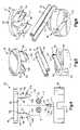
- FIG. 3is an exploded schematic pictorial illustration depicting the construction of a base section and cover section of the retainer of FIGS. 1 and 2 ;
- FIG. 4is an exploded schematic pictorial illustration, further illustrating the construction of the base and cover sections of the retainer
- FIG. 5is an exploded schematic pictorial illustration, further illustrating the construction of the base and cover sections of the retainer
- FIG. 6is an exploded schematic pictorial illustration further illustrating the construction of the base and cover sections of the retainer
- FIG. 7is a schematic sectional view depicting the relationship between the base and cover sections of the retainer of FIGS. 1–6 with portions of the suture disposed in passages in the retainer;
- FIG. 8is a schematic fragmentary sectional view, generally similar to FIG. 7 , depicting the manner in which end portions of projections on the cover section of the retainer are bonded to bottom portions of recesses in the base section of the retainer;
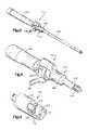
- FIG. 9is a highly schematized sectional view illustrating the construction of an improved applicator assembly which is utilized to interconnect sections of the retainer of FIGS. 1–7 in the manner illustrated schematically in FIG. 8 ;
- FIG. 10is a schematic pictorial illustration of one embodiment of the applicator assembly of FIG. 9 ;
- FIG. 11is an enlarged fragmentary schematic pictorial illustration of a portion of the applicator assembly of FIG. 10 , illustrating a trigger and spring housing;
- FIG. 12is an enlarged fragmentary schematic illustration of an end portion of the applicator assembly of FIG. 10 ;
- FIG. 13is a schematic illustration depicting the manner in which a suture may be looped around projections on the retainer of FIGS. 1–8 ;
- FIG. 14is a schematic sectional view, generally similar to FIG. 7 illustrating a second embodiment of the retainer
- FIG. 15is a schematic illustration, taken generally along the line of 15 — 15 of FIG. 14 , illustrating a relationship of the suture to a cover section of the retainer;
- FIG. 16is a schematic illustration, generally similar to FIG. 15 , illustrating the manner in which the suture may be looped around projections on the cover section of the retainer;
- FIG. 17is a schematic sectional view of another embodiment of the retainer.
- FIG. 18is a schematic sectional view of another embodiment of the retainer.
- FIG. 19is a schematic sectional view of another embodiment of the retainer.
- FIG. 20is a schematic plan view of another embodiment of the retainer.
- FIG. 21is a schematic sectional view, taken generally along the line 21 — 21 of FIG. 20 , further illustrating the construction of the retainer;
- FIG. 23is a schematic sectional view of another embodiment of the retainer.
- FIG. 24is a fragmentary schematic illustration depicting the manner in which the applicator assembly of FIGS. 9–12 may be utilized to move the retainer of FIGS. 1–8 and 13 – 23 into a cannula;
- FIG. 25is a fragmentary schematic illustration, generally similar to FIG. 12 , depicting the manner in which a shield may be provided on the distal portion of the applicator assembly of FIGS. 9–12 .
- An improved retainer 30is utilized to fixedly interconnect opposite portions 32 and 34 of a suture 36 .
- the portions 32 and 34 of the suture 36extend in opposite directions through the retainer 30 .
- An intermediate portion 38 of the sutureextends between the portions 32 and 34 and extends around body tissue 40 to the retainer 30 .
- the suture 36 and retainer 30could be connected with each other and/or the body tissue 40 in a manner which is different than the specific manner illustrated in FIG. 1 .
- the portions 32 and 34 of the suture 36may extend in the same direction from the retainer 30 .
- the suture 36 and retainer 30may be utilized to secure body tissue 40 in many different ways.
- the suture 36 and retainer 30may be utilized to secure one piece of body tissue to another piece of body tissue.
- the suture 36 and retainer 30may be utilized to secure soft body tissue to hard body tissue (bone).
- the suture 36 and retainer 30may be utilized to connect hard body tissue to hard body tissue in the manner disclosed in U.S. Pat. No. 6,238,395.
- the suture 36 and retainer 30may be disposed entirely within a patient's body or may engage a surface area on the patient's body.
- the suture 36can be constructed of a single filament or of a plurality of filaments.
- the suture 36may be formed of biodegradable or nonbiodegradable material.
- the retainer 30may be formed of biodegradable or nonbiodegradable material.
- the retainer 30may be desired to form the retainer 30 from Poly-L-Lactic Acid (PLLA) or other resorbable polymer.
- PLLAPoly-L-Lactic Acid
- the retainer and suturemay be formed of different materials.
- the suture 36 and retainer 30may both be formed of a biodegradable material.
- one of the suture 36 and retainer 30may be formed of a biodegradable material and the other one formed of a nonbiodegradable material.
- the retainer 30 and suture 36are positioned in a patient's body using open or minimally invasive surgical techniques, it is contemplated that it may be desired to tension the suture 36 with a predetermined force.
- a predetermined tensionis applied to the suture 36 by pulling the portions 32 and 34 of the suture from the retainer 30 with a predetermined force.
- the suture 36is tensioned with a force which is a function of the size and strength of the suture.
- the manner in which the suture 36 is tensioned with a predetermined forcemay be the same as is disclosed in U.S. Pat. No. 6,159,234 or in U.S. patent application Ser. No. 09/556,458 filed May 3, 2000 by Peter M. Bonutti and entitled Method And Apparatus For Securing Tissue.
- the suture 36is tensioned with a predetermined force by pulling the portions 32 and 34 of the suture before securing the retainer 30 to the suture to hold the suture.
- the retainer 30grips the portions 32 and 34 of the suture 36 to maintain a tension, corresponding to the predetermined force, in the suture.
- minimally invasive surgical techniquesdisclosed in the aforementioned U.S. patent application Ser. No. 09/941,185 filed Aug. 28, 2001 by Peter M. Bonutti and entitled Method of Performing Surgery may be utilized. It is believed that the utilization of minimally invasive surgical techniques may be particularly advantageous when used in association with a robotic mechanism and/or imaging apparatus in the manner disclosed in U.S. patent Ser. No. 10/102,413 filed Mar. 20, 2002 by Peter M. Bonutti. It is contemplated that a magnetic suturing system having a construction similar to that in U.S. patent application Ser. No. 10/005,652 filed by Peter M. Bonutti on Dec. 3, 2001 and entitled Magnetic Suturing System and Method may be used to position the suture 36 .
- the retainer 30includes a lower or base section 46 ( FIGS. 2 and 3 ) and an upper or cover section 48 .
- the portions 32 and 34 of the suture 36extend through passages 52 and 54 ( FIGS. 2 and 7 ) formed between the upper and lower sections 46 and 48 of the retainer 30 .
- the passages 52 and 54have a cross sectional area which is slightly greater than the cross sectional area of the suture 36 ( FIG. 7 ). Therefore, the portions 32 and 34 of the suture 36 can be readily pulled through the passages 52 and 54 when the retainer 30 is in the initial or undeformed condition illustrated in FIG. 7 . It should be understood that the passages 52 and 54 could have a configuration other than the configuration illustrated in FIG. 7 .
- the lower section 46 of the retainer 30includes a right (as viewed in FIG. 3 ) recess 58 and a left recess 60 .
- the right and left recesses 58 and 60have the same configuration and are disposed the same distance from a central axis of the circular lower section 46 of the retainer 30 .
- the recesses 58 and 60could have many different configurations, the illustrated recesses have elongated configurations with parallel longitudinal central axes which extend perpendicular to the central axis of the circular lower section 46 .
- the upper section 48has a circular body 64 from which right (as viewed in FIG. 3 ) and left projections 66 and 68 extend.
- the right and left projections 66 and 68have the same cross sectional configuration which corresponds to the cross sectional configuration of the recesses 58 and 60 ( FIGS. 4 , 5 , 6 , and 7 ).
- the projections 66 and 68have an elongated configuration with parallel longitudinal central axes which extend perpendicular the central axis of the circular body 64 of the upper section 48 of the retainer 30 .
- the projections 66 and 68are disposed the same distance from a central axis of the upper section 48 . It is contemplated that the projections 66 and 68 could have a configuration which is different than the specific configuration illustrated in FIGS. 4–7 .
- a center projection 72is disposed on the lower section 46 of the retainer 30 at a location midway between the right and left recesses 58 and 60 ( FIGS. 3 , 4 and 7 ).
- the left and right projections 66 and 68 on the upper section 48 of the retainer 30are telescopically received in the right and left recesses 58 and 60 in the lower section 46 of the retainer 30 ( FIGS. 2 , 3 , and 7 ). This results in the upper section 38 of the retainer being positioned in a coaxial relationship with the lower section 36 of the retainer.
- the center projection 72is disposed midway between the right and left projections 66 and 68 when they engage the right and left recesses 58 and 60 .
- the right and left recesses 58 and 60cooperate with the right and left projections 66 and 68 to orient the upper section of the retainer 48 with the longitudinal axes of the right and left projections 66 and 68 extending parallel to the longitudinal axis of the center section 72 .
- the center projection 72cooperates with the right and left projections to partially form the passages 52 and 54 .
- the bottom (as viewed in FIG. 7 ) of the passage 52is formed by a gripper surface area 78 .
- the bottom of the passage 54is formed by a gripper surface area 80 .
- the gripper surface areas 78 and 80 on the lower section 46face and are parallel to gripper surface areas 82 and 84 ( FIG. 7 ) on the upper section 48 .
- the gripper surface areas 78 , 80 , 82 and 84cooperate with the projections 66 , 68 and 72 to define the parallel passages 52 and 54 .
- the gripper surface areas 78 , 80 , 82 and 84may be roughened or knurled to enhance their ability to grip the suture 36 .
- the right and left projections 66 and 68have flat parallel longitudinally extending inner side surfaces 88 and 90 ( FIGS. 4 and 7 ).
- the inner side surfaces 88 and 90 on the projections 66 and 68extend perpendicular to the gripper surface areas 82 and 84 on the circular body 64 of the upper section 48 of the retainer 30 .
- the right and left projections 68 and 70have outer side surfaces 92 and 94 which extend parallel to the inner side surfaces 88 and 90 .
- passages 52 and 54By forming the passages 52 and 54 with elongated side surfaces, insertion of the portions 32 and 34 of the suture 36 into the passages is facilitated. This is because once a portion 32 or 34 of the suture 36 has been inserted into one of the passages 52 or 54 , the side surfaces of the passage maintain the leading end of the suture in a desired relationship with the passage as the suture continues to be moved into the passage.
- the center projection 72is effective to position the portions 32 and 34 of the suture 36 so that they are disposed on opposite sides of and equal distances from a central axis of the retainer 30 . This results in off setting movements being applied to the retainer 30 by forces transmitted to the retainer from the portions 32 and 34 of the suture 36 . Therefore, there is little or no tendency for the retainer 30 to rotate or flip relative to the body tissue 40 .
- the right and left projections 66 and 68 on the upper section 48 of the retainer 30are disposed in the recesses 58 and 60 in the lower section 46 of the retainer 78 ( FIG. 7 ) during insertion of the portions 32 and 34 of the suture 36 into the passages 52 and 54 in the retainer 30 .
- To hold the projections 66 and 68 in the recesses 58 and 60there is an interference fit between the projections and the recesses.
- the distance between an outer side surface 102 of the right recess 58 ( FIG. 7 ) and an inner side surface 104 of the right recessis slightly less than the distance between the outer side surface 92 and inner side surface 88 on the right projection 66 .
- the resulting interference between the right projection 66 and the right recess 58is effective to hold the right projection in the right recess.
- the interference fit between the projections 66 and 68 on the upper section 48 of the retainer with the recesses 58 and 60 in the lower section 46 of the retainerholds the two sections of the retainer against movement relative to each other during insertion of the portions 32 and 34 of the suture 36 into the passages 52 and 54 .
- the upper section 48 and lower section 46 of the retainer 30may be held against movement relative to each other by means other than an interference fit.
- latch surfaces on the projections 66 and 68may engage latch surfaces formed on the sides of the recesses 58 and 60 . These latch surfaces may have a generally wedge shaped configuration.
- a pinmay extend through at least a portion of the lower section 46 of the retainer and the projections 66 and 68 on the upper section 48 of the retainer to hold the upper section against movement relative to the lower section.
- the lower section 46 and upper section 48 of the retainer 30are formed as two separate pieces. However, it is contemplated that the lower and upper sections 46 and 48 of the retainer 30 could be formed as one piece. If this is done, relatively weak connectors may be provided between the projections 66 and 68 and the base section 46 to hold the base and upper sections 46 and 48 in a desired spatial relationship with each other during insertion of the portions 32 and 34 of the suture 36 into the passages 52 and 54 . The weak connectors may be broken to enable the portions 32 and 34 of the suture 36 to be gripped between the retainer sections 46 and 48 . Alternatively, a flexible strap may be formed between the base section 46 and upper section 48 . By deflecting the strap, the projections 66 and 68 may be inserted into the recesses 58 and 60 .
- the leading or lower (as viewed in FIG. 7 ) end portions of the projectionsengage flat bottom surfaces 118 and 120 of the recesses 58 and 60 ( FIG. 7 ).
- the flat bottom surfaces 118 and 120extend parallel to the gripper surface areas 78 and 80 on the lower section 46 and perpendicular to the side surfaces 102 , 104 , 110 and 112 of the recesses 58 and 60 .
- the center projection 72has a flat upper side surface 130 which extends parallel to the gripper surfaces 78 , 80 , 82 and 84 .
- the upper side surface 130 on the center projection 72is spaced from the upper section 48 when the end portions 124 and 126 of the projections 66 and 68 are in engagement with the bottom surfaces 118 and 120 of the recesses 58 and 60 .
- the center projection 72may be disposed in engagement with the upper section 48 when the end portions 124 and 126 of the projections 66 and 68 are in engagement with the bottom surfaces 118 and 120 of the recesses 58 and 60 .
- the portions 32 and 34 of the suture 36can be freely moved in the passages 52 and 54 to enable the retainer 60 to be slid along the suture 36 to a desired position relative to the body tissue 40 .
- the retainer 30may be slid along the suture 36 under the influence of force manually applied against the retainer or under the influence of force applied against the retainer by a surgical instrument, such as forceps. As this occurs, the intermediate portion 38 ( FIG. 1 ) of the suture is tightened around the body tissue with a desired force.
- the retainer 30Once the retainer 30 has been positioned in a desired location relative to the body tissue 40 and the suture 36 tensioned with a predetermined force, the retainer is plastically deformed from the initial condition illustrated in FIG. 7 to the condition illustrated in FIG. 8 . Plastic deformation of the retainer 30 results in the size of the passages 52 and 54 being decreased. In addition, the upper side 130 on the center projection 72 moves into engagement with the upper section 48 of the retainer 30 . Engagement of the center projection 72 with the upper section 48 of the retainer 30 tends to limit the extent to which the lower and upper section 46 and 48 of the retainer are pressed together to thereby limit plastic deformation of the retainer 30 .
- a member 140( FIG. 8 ) is moved into a groove 142 in the lower section 46 .
- a second member 144engages a flat outer side surface 146 on the upper section 48 of the retainer 30 .
- the lower and upper sections 46 and 48 of the retainer 30are firmly pressed together by force transmitted between the members 140 and 144 through the retainer. While the lower and upper sections 46 and 48 of the retainer 30 are gripped between the members 140 and 144 with a clamping action, energy is transmitted from the member 144 to the retainer 30 .
- the energy applied to the retainer 30is effective to heat the end portions 124 and 126 of the projections 66 and 68 into a transition temperature range for the polymeric material of the projections.
- Force applied against the retainer 30 by the members 140 and 144causes the heat softened material of the projections 66 and 68 to flow in the recesses 58 and 60 .
- material of the lower section 46is heated and also flows in the recesses 58 and 60 .
- the heated material of the projections 66 and 68may be forced upward toward the portions 32 and 34 of the suture 36 .
- the heated materialtends to bond to the portions 32 and 34 of the suture 36 it should be understood that the extent of deformation and flow of the heat softened material of the projections 66 and 68 may be and probably will be greater than the extent illustrated schematically in FIG. 8 .
- the retainer 30is constructed so that the center projection 72 is deformed to the same extent as the projections 66 and 68 , heat softened material of the center projection would flow into the passages 52 and 54 .
- the upper section 48 of the retainer 30has the construction shown in FIG. 4 , the upper end portion of the center projection would engage the flat lower side surface of the body 64 .
- the upper section 48 of the retainer 30may be formed with a recess to receive the upper end portion of the center projection 72 . This recess may have the same configuration as the recesses 58 and 60 in the lower section 46 of the retainer 30 .
- the retainer 30may be constructed with the center projection 72 extending from the upper section 48 of the retainer. If this is done, the center projection 72 from the upper section 48 of the retainer may have the same configuration as the illustrated configuration of the center projection in FIGS. 4 and 5 .
- a recessmay be provided in the lower section 46 to receive a portion of a center projection from the upper section 48 of the retainer 30 .
- the size of the passages 52 and 54is decreased. This results in the portions 32 and 34 of the suture 36 being firmly clamped between the gripper surface areas 78 and 80 on the lower section 46 and the gripper surface areas 82 and 84 on the upper section 48 of the retainer 30 .
- the force applied to the portions 32 and 34 of the suture 36 by the gripper surface areas 78 , 80 , 82 and 84 on the lower and upper sections 46 and 48 of the retainer 30is effective to deform the suture from the circular cross sectional configuration illustrated in FIG. 7 to a generally oval cross sectional configuration illustrated schematically in FIG. 8 .
- the illustrated suture 36is a monofilament, it is contemplated that the suture could be formed by a plurality of filaments which are braided or twisted together.
- the energy which is applied to the retainer 30 by the member 144may be thermal energy, vibratory energy, or light energy.
- the energymay be transmitted by radio frequency waves, ultrasonic waves, heat waves, or light waves.
- the energymay be vibratory ultrasonic or radio frequency energy.
- the groove 142may be omitted and a flat member, similar to the member 144 , may be pressed against the lower section 46 of the retainer 30 .
- Energymay be transmitted to the retainer through either the member 140 or the member 144 or both of the members 140 and 144 .
- the portions 32 and 34 of the suture 36are clamped between the lower section 46 and upper section 48 of the retainer 30 .
- the clamping force applied against the portions 32 and 34 of the suture 36 by the retainer 30holds the retainer and the portions of the suture against relative movement. This results in the suture 36 and retainer 30 being securely interconnected.
- the end portions 124 and 126 of the projections 66 and 68have a pointed configuration.
- the end portion 124 of the projection 66includes a flat side surface area 150 which intersects a flat side surface area 152 at a linear point or peak. Therefore, there is line contact between the end portion 124 of the right projection 66 and the flat bottom surface 118 of the right recess 58 .
- the end portion 126 of the left projection 68has a flat side surface 156 which intersects a flat side surface 158 at a linear point or peak on the end portion 126 of the left projection 68 . This results in line contact between the pointed end portion of the left projection 68 and the flat bottom surface 120 of the left recess 60 .
- the end portions 124 and 126 of the projections 66 and 68may have a conical configuration if desired.
- the end portions of the projectionsare effective to function as energy directors for ultrasonic vibratory energy.
- the pointed end portions 124 and 126 of the right and left projections 66 and 68are effective to direct ultrasonic vibratory energy transmitted from the member 144 to the ends of the projections and to the bottom surfaces 118 and 120 of the recesses 58 and 60 .
- the pointed configuration of the end portions 124 and 126 of the projections 66 and 68concentrates the energy and facilitates melting of the material of the projections. To a lesser extent, the material of the lower section 46 of the retainer 30 is melted adjacent to the bottom surfaces 118 and 120 . This results in a secure bonding and interconnection between the lower and upper sections 46 and 48 of the retainer 30 .
- An improved applicator assembly 172( FIGS. 9–12 ) is utilized to grip the retainer 30 with a constant predetermined force, to move the retainer 30 along the suture 36 to a desired position relative to the body tissue 40 , and to transmit energy to the retainer 30 .
- the applicator assembly 172may be used to perform any one or more of foregoing functions rather than all of the functions.
- the applicator assembly 172includes a rigid energy transmission member 174 ( FIG. 9 ) which corresponds to the member 144 in FIG. 8 .
- a rigid tubular force transmitting member 176extends around and is coaxial with the cylindrical energy transmission member 174 .
- the cylindrical force transmitting member 176corresponds to the member 140 in FIG. 8 .
- a biasing assembly 178continuously urges the force transmitting member 176 toward the left (as viewed in FIG. 9 ) with a constant predetermined force.
- the illustrated embodiment of the biasing assembly 178includes a helical spring 180 which is disposed between an annular flange 182 on a reaction member 184 and an annular piston 186 .
- the annular piston 186is fixedly connected to a housing 188 .
- the housing 188is connected to the tubular force transmitting member 176 .
- the reaction member 184is fixedly connected to a manually engagable handle 194 .
- a trigger 198is pivotally connected with the handle 194 .
- the trigger 198is manually pivotal in a clockwise direction (as viewed in FIGS. 9 and 11 ). Clockwise pivotal movement of the trigger 198 transmits force through a yoke 200 .
- the force transmitted through the yoke 200moves the housing 188 toward the right (as viewed in FIGS. 9 and 11 ). This rightward movement of the housing 188 moves a flange 204 on the right (as viewed in FIGS. 9 and 12 ) or distal end of the tubular force transmitting member 176 away from a circular end surface 206 on the energy transmission member 174 .
- the rightward (as viewed in FIGS. 9 and 12 ) movement of the force transmitting member 176 relative to the energy transmission member 174increases space between the flange 204 and end surface 206 on the energy transmission member 174 .
- Increasing the space between the flange 204 and the end surface 206enables the retainer 30 to be positioned between the flange 204 and the end surface 206 with the portions 32 and 34 of the suture 36 extending through the passages 52 and 54 in the retainer 30 in the manner illustrated in FIG. 7 .
- the flange 204When the retainer 30 is positioned in the gap between the end surface 206 ( FIGS. 9 and 12 ) on the energy transmission member 174 and the flange 204 connected with the force transmitting member 176 , the flange 204 is positioned in the groove, 142 in the retainer 30 in the same manner as in which the member 140 is illustrated as engaging the groove 142 in FIG. 8 .
- the end surface 206 ( FIGS. 9 and 12 ) on the energy transmission member 174is disposed in engagement with the surface 146 on the upper section 48 of the retainer 30 in the same manner as in which the member 144 ( FIG. 8 ) engages the surface 146 .
- the trigger 198is released.
- the biasing spring 180is effected to urge the housing 188 toward the left (as viewed in FIGS. 9 and 11 ).
- the leftward force applied by the spring 180 against the housing 188is transmitted through the force transmitting member 176 and flange 204 to the retainer 30 .
- the spring 180is effective to apply a constant predetermined biasing force to the piston ring 186 . This constant biasing force is transmitted through the housing 188 and force transmitting member 176 to the retainer 30 .
- the force applied against the retainer 30is ineffective to cause significant plastic deformation of the material of the retainer 30 .
- the end portions 124 and 126 ( FIG. 7 ) of the right and left projections 66 and 68are pressed against the bottom surfaces 118 and 120 of the recesses 58 and 60 with a constant force.
- the portions 32 and 34 of the suture 36are freely movable in the passages 52 and 54 .
- the retainer 30While the retainer 30 is gripped with a predetermined constant force by the applicator assembly 172 , the retainer is moved to a desired position relative to the body tissue 40 . To position the retainer 30 relative to the body tissue, the surgeon holds the handle 194 of the applicator assembly 172 in one hand and tensions the portions 32 and 34 of the suture 36 with the other hand. The surgeon then manually applies force against the handle 194 to slide the retainer 30 along the tensioned portions 32 and 34 of the suture 36 toward the body tissue 40 .
- the relatively long force transmitting member 176 and energy transmitting member 174enable the applicator assembly 172 to move the retainer 30 through a small incision to a remote location in a patient's body as the retainer slides along the suture 36 .
- the suture 36may be moved through a cannula to a location disposed within a patient's body. The suture 36 is then positioned relative to the tissue 40 at the remote location in the patient's body. However, it should be understood that the cannula may be omitted and the suture 36 moved through an open incision.
- the portions 32 and 34 of the suturemay be positioned in the passages 52 and 54 through the retainer while the retainer is disposed outside of the patient's body.
- the retaineris gripped by the applicator assembly 172 .
- the flange 204 on the force transmitting member 176 and end surface 206 on the energy transmission member 174 of the applicator assembly 172are effective to apply a predetermined constant force against opposite sides of the retainer 30 to securely grip the retainer with the applicator assembly 172 .
- the applicator assembly 172While the retainer is gripped by the applicator assembly 172 , the end portions 32 and 34 of the suture are manually tensioned and the retainer is slid along the portions 32 and 34 of the suture toward the body tissue. As the retainer 30 is slid along the suture 36 toward the body tissue 40 , the applicator assembly 172 moves the retainer into the patient's body. As the retainer 30 is moved into the patient's body, it is gripped with a constant predetermined force by the applicator assembly 172 .
- the retainer 30may be gripped by the applicator assembly 172 outside of the patient's body prior to insertion of the portions 32 and 34 of the suture through the passages 52 and 54 .
- the portions 32 and 34 of the suture 36may then be inserted through the passages 52 and 54 in the retainer 30 while the retainer is gripped by the applicator assembly 172 .
- insertion of the portions 32 and 34 of the suture 36 through the passages 52 and 54 in the retainer 30may be performed with the retainer inside the patient's body.
- the applicator assembly 172is utilized to move the retainer 30 through a cannula into the patient's body before the suture 36 is inserted into the passages 52 and 54 through the retainer, suitable instruments may be utilized to grip the portions 32 and 34 of the suture in the patient's body and to move the portions 32 and 34 of the suture through the passages 52 and 54 .
- the instruments which engage the suture and move it through the passages 52 and 54 while the retainer 40 is gripped by the applicator assembly 172may extend through the cannula along with the applicator assembly.
- the instruments which move the portions 32 and 34 of the suture 36 through the passages 52 and 54may be moved into the patient's body through a cannula spaced from the cannula through which the applicator assembly 172 moves the retainer into the patient's body.
- the suture 36 and retainer 30may be desired to position the suture 36 and retainer 30 in a patient's body with a robotic mechanism.
- the manually engagable handle 194 and trigger 198 on the applicator assembly 172may be eliminated.
- the remainder of the applicator assemblymay then be connected with the robotic mechanism.
- a suitable motormay be provided in the robotic mechanism to move the force transmitting member 176 against the influence of the biasing spring 180 .
- the retainer 30would be gripped between the flange 204 on the force transmitting member 176 and end surface 206 on the energy transmission member 174 with a constant force.
- the robotic mechanism with which the applicator assembly 172 is connectedmay have a plurality of adaptive arms which are effective to move the retainer 30 and other instruments in a patient's body.
- the robotic mechanismmay be a reprogrammable, multifunctional manipulator designed to move through various program motions for the performance of selected one of a plurality of surgical procedures.
- the robotic mechanismmay have manually operable controls which provide for interaction between a surgeon and the robotic mechanism.
- the robotic mechanismmay have any one of many different constructions and may be operated in any one of many different manners, including those disclosed in U.S. patent application Ser. No. 10/102,413 filed Mar. 20, 2002 by Peter M. Bonutti and entitled Methods of Securing Body Tissue.
- the applicator assembly 172When the applicator assembly 172 is to be utilized in association with a robotic mechanism, it is believed that it may be desired to utilize a monitor or display in association with the robotic mechanism.
- a single imaging device or a plurality of imaging devicesmay be used. If a plurality of imaging devices are used, it is contemplated that stereoscopic and/or video stereoscopic viewing at a location where a surgical procedure is being performed may be accommodated by the imaging apparatus.
- the imaging apparatusmay include a plurality of endoscopes.
- a navigation systemmay be utilized to provide inputs to the computer to assist in the control of the robotic mechanism and the performance of a surgical procedure.
- the navigation systemmay be an optical navigation system in which end portions of navigation members are illuminated by light.
- the navigation membersmay be connected with one or more tissues in a patient's body.
- the tissue with which the navigation members are connectedmay either bone or soft tissue.
- imaging devicessuch as a fluoroscope, and/or magnetic resonance imaging unit and/or ultrasonic imaging unit may be utilized with the robotic mechanism.
- endoscopesmay be utilized in association with the various imaging units.
- the imaging units and robotic mechanismsmay have a construction and cooperate with each other in the same manner as described in the aforementioned U.S. patent application Ser. No. 10/102,413 filed Mar. 20, 2002 by Peter M. Bonutti.
- the portions 32 and 34 of the suture 36are pulled with a predetermined force. This results in a predetermined tension being established in the portions 32 and 34 of the suture 36 . While the predetermined tension is maintained in the suture 36 , the retainer 30 is plastically deformed to connect the retainer with the portions 32 and 34 of the suture 36 and hold the portions 32 and 34 of the suture against movement relative to each other and the retainer 30 .
- energyis transmitted from an energy source 212 ( FIG. 9 ) through the energy transmission member 174 to the retainer 30 . At this time, the retainer 30 is clamped between the flange 204 on the force transmitting member 176 and the end surface 206 on the energy transmission member 174 .
- the energy source 212is a source of ultrasonic vibratory energy at a frequency above that which can normally be detected by the human ear, that is about 16 to 20 kilohertz. Although there are a wide range of frequencies which may be utilized, it is believed that it may be desirable to use ultrasonic energy having a frequency of between 20 kilohertz and 70 kilohertz. It is believed that it may be desired to use ultrasonic vibratory energy of a frequency between 39.5 and 41 kilohertz.
- a foot pedal actuated switch 214FIG. 9
- ultrasonic vibratory energyis transmitted through the energy transmission member 174 to the retainer 30 .
- the ultrasonic vibratory energycreates frictional heat at the pointed end portions 124 and 126 of the projections 66 and 68 .
- the frictional heat provided by the ultrasonic vibratory energyis effective to heat material of the suture retainer 30 into its transition temperature range while the material of the suture 36 remains at a temperature below its transition temperature range.
- the suture 36may be formed of a material having a transition temperature range which is above 190 degrees Celsius.
- the suture retainer 40may have a transition temperature range which begins at a temperature below 190 degrees Celsius.
- transition temperature range for the suture 36could be co-extensive with the transition temperature range for the retainer 30 .
- the transition temperature range of the suture 36could extend below the transition temperature range of the retainer 30 .
- Ultrasonic vibratory energyis transmitted from the energy transmission member 174 to the upper section 48 of the retainer 30 .
- the right and left projections 66 and 68( FIG. 7 ) from the upper section 48 of the retainer 30 function as energy directors which direct the ultrasonic vibratory energy to the locations where the end portions 124 and 126 of the projections 66 and 68 engage the bottom surfaces 118 and 120 of the recesses 58 and 60 in the lower section 46 of the retainer 30 .
- the pointed end portions 124 and 126 of the projections 66 and 68concentrate the vibratory energy transmitted through the energy transmission member 174 at the locations where the projections engage the bottom surfaces 118 and 120 of the recesses 58 and 60 .
- the ultrasonic vibratory energyis effective to soften and make the material forming the end portions 124 and 126 of the projections 66 and 68 flowable under the influence of the constant predetermined force transmitted from the biasing spring 180 through the force transmission member 176 and flange 204 to the lower section 46 of the retainer 30 .
- the lower section 46 of the retainer 30moves toward the upper section 48 of the retainer. This results in material which originally formed the pointed end portions 124 and 126 of the projections 66 and 68 being deflected sideways in the lower (as viewed in FIG. 7 ) portions of the recesses 58 and 60 .
- ultrasonic vibratory energymay be applied to the retainer if desired.
- thermal or light (laser) energymay be applied to the retainer if desired.
- the energy application apparatusmay be separate from the apparatus which is used to position the retainer relative to the body tissue 40 and suture 36 .
- the retainer 30may be positioned relative to body tissue 40 and the suture 36 manually or by using a first apparatus. Energy may then be applied to the retainer 30 using a second apparatus.
- the heated, flowable material of the end portions 124 and 126 of the projections 66 and 68may flow along the side surfaces 102 , 104 , 110 and 112 of the recesses 58 and 60 . Some of the material of the end portions 124 and 126 of the projections 66 and 68 may engage and bond to the portions 32 and 34 of the suture 36 .
- the portions 32 and 34 of the suture 36are deflected from their original circular configuration ( FIG. 7 ) to an oval configuration under the influence of force applied against the portions of the suture disposed between the lower section 46 and upper section 48 of the retainer 30 .
- the portions 32 and 34 of the suture 36are resiliently deflected to the configuration illustrated schematically in FIG. 8 , there is minimal bonding of the material with the retainer 30 to the suture 36 and no significant loss of strength of the suture. Due to the clamping action between the flange 204 and end surface 206 on the energy transmission member 174 ( FIG. 9 ) against the retainer 30 , the overall height of the retainer is decreased. At the same time, the overall diameter of the retainer increases.
- the material of the retainer 30cools and there is an ultrasonic welding of the lower section 46 of the retainer to the upper section 48 of the retainer.
- the bonding between the lower section 46 and upper section 48 of the retainer 30occurs mainly between the projections 66 and 68 and the lower section 48 of the retainer. There may be some bonding of the center projection 130 to the circular body 64 of the upper section 48 of the retainer. In addition, there may be some bonding material of the lower section 46 and upper section 48 of the retainer to the portions 32 and 34 of the suture 36 .
- the portions 32 and 34 of the suture 36are held against movement relative to each other and to the retainer primarily 30 by a clamping action between surfaces on the lower section 46 and surfaces on the upper section 48 of the retainer.
- the portions 32 and 34 of the suture 36are securely gripped between the gripper surface areas 78 and 80 on the lower section 46 of the retainer 30 and the gripper surface areas 82 and 84 on the upper section 48 of the retainer 30 .
- the applicator assembly 172could have a different construction and/or mode of operation.
- the applicator assembly 172may have any one of the constructions and mode of operations disclosed in U.S. patent application Ser. No. 10/076,919 filed Feb. 15, 2002 by Peter M. Bonutti, et al and entitled Method of Using Ultrasonic Vibration to Secure Body Tissue.
- a retainer having a construction similar to that illustrated in FIGS. 1–8may be preferred, it is contemplated that the applicator assembly 172 of FIGS. 9–12 may be utilized with retainers having a different construction.
- the applicator assembly 172may be utilized in association with a retainer having any one of the constructions disclosed in the aforementioned U.S. patent application Ser. No. 10/076,919 filed Feb. 15, 2002 by Peter M. Bonutti or any one of the constructions disclosed in U.S. Pat. No. 6,010,525.
- the leading end portion of the force transmitting member 176extends part way around the end surface 206 on the energy transmission member 174 .
- the shield 220has an inner side surface 222 which forms a portion of a cylinder. The side surface 222 engages the cylindrical periphery of the retainer 30 to position the retainer relative to the energy transmission member 174 in a direction transverse to a longitudinal central axis of the energy transmission member.
- the shield 220is effective to at least partially block engagement of body tissue with the retainer 30 as the retainer is positioned in a patient's body and as energy is transmitted to the retainer from the energy transmission member 174 . It is contemplated that the shield 220 could be constructed in such a manner as to extend completely around the retainer 30 . This would allow use of the applicator assembly 172 in a moist environment or in an aqueous environment in which the retainer is completely or almost completely submerged in liquid.
- the force transmitting member 176has a flange 204 which engages the groove 142 in the same manner as which the member 140 is schematically depicted as engaging a groove 142 in FIG. 8 .
- the flange 204could be eliminated and a circular end plate provided at the distal end of the force transmitting member 176 .
- the use of a platewould provide for a wider area of engagement of the force transmitting member 176 with the lower section 46 of the retainer 30 .
- the use of a circular end plate in place of the flange 204would allow the groove 142 in the lower section 46 of the retainer to be eliminated.
- the portions 32 and 34 of the suturePrior to connecting the retainer 30 with the suture 36 , the portions 32 and 34 of the suture are pulled with a predetermined tension. Tensioning the suture with a predetermined force may be accomplished in the manner disclosed in the aforementioned U.S. patent application Ser. No. 09/556,458 filed May 3, 2000 by Peter M. Bonutti and entitled Method and Apparatus For Securing Tissue or in the manner disclosed in U.S. patent application Ser. No. 10/102,413 filed Mar. 20, 2002 by Peter M. Bonutti and entitled Methods of Securing Body Tissue.
- the applicator assembly 172is utilized to interconnect the lower section 46 and upper section 48 of the retainer in the manner previously discussed.
- the portion 32 of the sutureapplies force against the lower section 46 of the retainer on the right (as viewed in FIG. 7 ) side of the central axis of the retainer.
- the portion 34 of the sutureapplies force against the lower section 46 of the retainer on the left side of the center projection 72 . This results in the application of offsetting movements to the lower section 46 of the retainer. Therefore, the retainer 30 does not tend to rotate on an axis disposed between the portions 32 and 34 of the suture 36 and is stable relative to the body tissue 40 .
- the applicator assembly 172may be used to position the retainer 30 relative to body tissue.
- a surgeonmay grasp the retainer 30 with one hand and tension the portions 32 and 34 of the suture 36 with the other hand. The surgeon would then manually apply force against the retainer 30 to slide the retainer along the tensioned portions 32 and 34 of the suture toward the body tissue. Rather than gripping the retainer 30 with one hand, the surgeon may grip the retainer 30 with a manually actuated instrument.
- the energy sourcemay have any of the constructions disclosed in U.S. Pat. No. 6,368,343. Alternatively, the energy source may have the construction disclosed in U.S. Pat. No. 3,513,848.
- the portions 34 and 36 of the sutureextend straight through the retainer 30 in a generally parallel relationship with each other.
- the portions 34 and 36 of the suturemay be looped around portions of the retainer to increase the strength of the connection between the suture 36 and the retainer 30 .
- the sutureis looped around the projections 66 and 68 from the upper section 48 of the retainer.
- the portion 32 of the sutureis inserted through the passage 52 between the right projection 66 from the upper section 48 of the retainer.
- the portion 32 of the sutureis then wrapped around the projection 66 and again inserted through the passage 52 to form a loop around the projection 66 .
- the portion 34 of the suture 36is looped around the projection 68 from the upper section 48 of the retainer 30 in the same manner as in which the portion 32 of the suture is looped around the projection 66 .
- the portions 32 and 34 of the suture 36are moved in opposite directions into the retainer 30 .
- the sutureis moved downward (as viewed in FIG. 13 ) through the passage and then wrapped upwardly around the projection 66 in a counter clockwise direction (as viewed in FIG. 13 ) and again moved downward through the passage 52 .
- the portion 34 of the sutureis to be positioned in the passage 54 in the retainer 30 , the portion 34 of the suture is first moved upward (as viewed in FIG. 13 ) through the passage 54 and then wrapped in a counter clockwise direction about the projection 68 .
- the portion 34 of the sutureis wrapped around the projection 68 , the portion 34 of the suture is again inserted through the passage 54 . This results in the formation of a loop 232 around the projection 68 .
- the intermediate portion 38 of the suture 36extends upward (as viewed in FIG. 13 ) from the loop 230 and extends downward (as viewed in FIG. 13 ) from the loop 232 .
- both of the loops 230 and 232could be formed around both of the projections 66 and 68 .
- the portion 32 of the suture 36would be moved downward (as viewed in FIG. 13 ) through the passage 52 and looped around the outside of the projection 66 across the upper (as viewed in FIG. 13 ) end portion of the center projection 72 and downward around the left projection 68 , across the bottom (as viewed in FIG. 13 ) of the center projection 72 and again wrapped around the outside of the right projection 66 .
- the portion 32 of the suture 36would then be moved downward for a second time, through the passage 52 .
- the portion 34 of the suture 36is moved upward (as viewed in FIG.
- a retainer 30 aincludes a lower section 46 a and an upper section 48 a .
- the lower section 46 ahas a pair of recesses 58 a and 60 a .
- the recesses 58 a and 60 ahave the configuration as the recesses 58 and 60 of FIGS. 1–8 .
- Right and left projections 66 a and 68 aextend downward (as viewed in FIG. 14 ) from the upper section 48 a into the recesses 58 a and 60 a in the lower section 60 a .
- the portions 32 a and 34 a of the suture 36 aare disposed in a side-by-side relationship in a single passage 240 ( FIG. 14 ) which extends between projections 66 a and 68 a from the portion 48 a of the retainer 30 a.
- end portions 124 a and 126 a ( FIG. 14 ) of the projections 66 a and 68 aare pressed against bottom surfaces of the recesses 58 a and 60 a in the manner previously described in conjunction with the embodiment of the invention illustrated in FIGS. 1–8 .
- the projections 66 a and 68 ahave the same configuration as the projections 66 and 68 of FIGS. 3–7 . Therefore, there is line contact between the tapered end portions 124 a and 126 a of the projections 66 a and 68 a and the flat bottom surfaces of the recesses 58 a and 60 a.
- the portions 32 a and 34 a of the suture 36 aare inserted in opposite directions through the passage 240 formed between the lower section 46 a and upper section 48 a of the retainer 30 a .
- the retainer 30 ais slid along the suture 36 a to a desired position relative to body tissue while the retainer is gripped with a constant predetermined force by the applicator assembly 172 . If desired, the retainer 30 a may be manually gripped and slid along the portions 32 a and 34 a of the suture 36 a.
- a suitable source of energywill have to be provided to effect heating of the retainer.
- This source of energymay have any one of the constructions disclosed in U.S. Pat. Nos. 3,513,848 and 6,368,343.
- the source of energymay have a known construction and be a source of thermal in light (laser) energy.
- the end portions 124 a and 126 a of the projections 66 a and 68 aare softened and deformed under the influence of the constant predetermined force applied against the retainer 30 a by the applicator assembly 172 As this occurs, the distance between the lower section 46 a and upper section 48 a is decreased and the portions 32 a and 34 a of the suture 36 a are gripped between flat gripper surfaces 242 and 244 formed on the upper section 48 a and lower section 46 a of the retainer 30 a.
- the portions 32 a and 34 a of the suture 36 aextend straight through the passage in opposite directions.
- the portions 32 a and 34 a of the sutureare looped around the projections 66 a and 68 a in the same manner as previously described in conjunction with FIG. 13 . This results in the formation of loops 230 a and 232 a around the projections 66 a and 68 a .
- the portions 32 a and 34 a of the suture 36 aare positioned in the passage 240 at locations equal distances from the center of the retainer 30 a . This minimizes any movement resulting from forces applied to the retainer 30 a by the suture 36 a and increases the stability of the retainer on the body tissue.
- a single projection 262extends from the upper section 48 b of the retainer 30 b .
- the projection 262is offset to one side of the suture 36 b .
- the projection 262has a pointed end portion 264 which is engagable with a flat upper side surface 266 on the lower portion 46 b of the retainer 30 b .
- the pointed end portion 264 of the projection 262has the same general configuration as the pointed end portions 124 and 126 of the projections 66 and 68 in FIG. 7 . However, the pointed end portion 264 of the projection 262 may have a conical configuration if desired.
- the portion 32 b of the suture 36 bis inserted through the nonlinear passage 250 in the lower section 46 b and through the nonlinear passage 258 in the upper section 48 b of the retainer 30 b .
- the portion 34 b of the sutureis inserted through the nonlinear passage 252 in the lower portion 46 b and through the nonlinear passage 256 in the upper portion 48 b , in the manner indicated schematically in FIG. 17 .
- the lower section 46 b and upper section 48 bare then gripped by an applicator assembly which may have the same construction as the applicator assembly 172 of FIGS. 9–12 .
- the surgeongrips the applicator assembly with one hand and the portions 32 b and 34 b of the suture 36 b with the other hand.
- the retainer 30 bis then slid along the suture 36 b toward the body tissue around which the intermediate portion 38 b of the suture extends.
- the end portion ( FIG. 12 ) of the applicator assembly 172moves through the cannula and slides the retainer 30 b along the suture 36 b to a position that is engagement with the body tissue, that is, to a position similar to that in FIG. 1 for the retainer 30 .
- the applicator assemblygrips the retainer with a constant predetermined force.
- the projection 262functions as an energy director which concentrates energy applied to the upper section 48 of the retainer 30 b by the end surface 206 of the energy transmission member 174 ( FIG. 9 ).
- the concentrated ultrasonic vibratory energy transmitted from the energy transmission member 174heats the material of the projection 262 ( FIG. 17 ) and the material of the base section 46 b engaged by the projection into its transition temperature range. As this occurs, there is a softening and deforming of the material of the projection 262 .
- a flat lower side surface 270 on the upper portion 48 b of the retainer 30 b and the flat upper side surface 266 of the lower portion 46 b of the retainermove into engagement with each other.
- Material of the retainer 30 btends to flow into the passages 250 , 252 , 256 and 258 formed in the lower and upper sections 46 b and 48 b of the retainer 30 b .
- the portions 32 b and 34 b of the suture 36 bare firmly clamped between the side surfaces 266 and 270 on the lower section 46 b and upper section 48 b of the retainer 30 b.
- the suture 36 bmay be formed by a single filament or a plurality of filaments.
- the suture 36 bmay be formed of biodegradable or nonbiodegradable material. It is contemplated that it may be desired to form the suture 36 b of the same material as the retainer 30 b . However, the retainer 30 b and suture 36 b may be formed of different materials.
- a robotic mechanismmay be utilized to position the retainer 30 b and/or suture 36 b relative to body tissue.
- a robotic mechanismmay be utilize in association with the retainer 30 b and/or suture 36 b in the manner described in the aforementioned U.S. patent application Ser. No. 10/102,413 filed Mar. 20, 2002 by Peter M. Bonutti and entitled Methods of Securing Body Tissue.
- the suture 36 c and retainer 30 care to be utilized in association with body tissue, the suture 36 c is positioned relative to the body tissue. The portion 32 c of the suture 36 c is then moved through the passages 278 and 280 in the lower section 46 c of the retainer 30 c . The portion 34 c of the suture 36 c is moved through the passages 282 and 284 of the lower section 46 c of the retainer 30 c.
- the upper section 48 c of the retainer 30 cis then positioned in the recess 274 with the projections 288 and 290 disposed in linear engagement with a flat upwardly facing side surface 298 on the lower section 46 c of the retainer 30 c .
- the pointed ends of the projections 292 and 294do not engage the suture 36 c .
- the retainer 30 cis gripped by the distal end portion ( FIG. 12 ) of the applicator assembly 172 . This results in the retainer 30 c being gripped with a constant predetermined force transmitted to the retainer 30 c from the biasing spring 180 ( FIG. 9 ) through the force transmitting member 176 .
- This energyheats the projections 288 and 290 and portions of the lower section 46 c into a transition temperature range. As this occurs, the material of the projections 288 and 290 softens and flows relative to the suture 36 c and lower and upper sections 46 c and 48 c of the retainer 30 c .
- the lower and upper sections 46 c and 48 c of the retainer 30 care clamped together with a constant predetermined force by the applicator assembly 172 as the material of the projections 288 and 290 is heated.
- the lower and upper sections 46 c and 48 c of the retainer 30 cgrip the suture 36 c with a clamping action.
- Material of the retainer 36 cis subsequently allowed to cool and the trigger 198 on the applicator assembly 172 is actuated to release retainer 30 c .
- the lower section 46 c and upper section 48 c of the retainerare bonded together.
- the suture 36 cis primarily secured against movement relative the retainer 30 c by clamping the portions 32 c and 34 c of the suture 36 c between the lower section 46 c and the upper section 48 c of the retainer 30 c .
- the suture 36 cis slightly deformed, in the manner illustrated schematically in FIG. 8 , there is no significant weakening of the suture 36 c.
- the upper section 48 c of the retainer 30 cis separate from the lower section 46 c and is manually moved into the recess 274 after the portions 32 c and 34 c of the suture 36 c have been positioned in the passages 278 , 280 , 282 and 284 .
- the upper section 48 c of the retainer 30 ccould be connected with the lower section 46 c .
- the upper section 48 cmay be positioned in the recess 274 .
- An interference fitmay be provided between the lower and upper sections 46 c and 48 c to hold the upper section in the recess 274 .
- one or more flexible connectorsmay be used to interconnect the lower and upper sections.
- the connectormay be a flexible strap. If desired, the connector may be weak sections which are easily broken as the upper section 48 c moves into the recess 274 .
- the suture 36extends through passages in the retainer 30 and is clamped in place.
- the sutureextends through passages in the retainer and is wrapped around a portion of the retainer, in a manner similar to that previously described in conjunction with the embodiment of the invention illustrated in FIG. 13 , prior to being clamped in place by interconnecting of the lower and upper sections of the retainer. Since the embodiment of the invention illustrated in FIG. 19 is generally similar to the embodiments of the invention illustrated in FIGS. 1–8 and 14 – 18 , similar numerals will be utilized to indicate similar components, the suffix letter, “d” being associated with the numerals of FIG. 19 to avoid confusion.
- a retainer 30 dis associated with a suture 36 d .
- the retainer 30 dhas a lower section 46 d and an upper section 48 d .
- the suture 36 dhas a portion 32 d and a portion 34 d which extend through the retainer 30 d .
- An intermediate portion 38 d of the suture 36 dextends between the portions 32 d and 34 d of the suture and may extend around body tissue in the manner illustrated schematically for the suture 36 in FIG. 1 .
- the lower section 46 d of the retainer 30 dhas a cylindrical central projection or post 310 .
- the portion 32 d of the suture 36 dextends through a passage 314 in the lower section 46 d of the retainer 30 d and is looped for a plurality of turns around the central projection 310 .
- the portion 32 d of the suture 36 dextends from the loops around the central projection 310 through a passage 316 in the upper section 48 d of the retainer 30 d .
- the portion 34 d of the suture 36 dextends through a passage 320 in the lower section 46 d and is wrapped for a plurality of loops around the central projection 310 .
- the portion 34 d of the suture 36 dextends from the central projection 310 through a passage 322 in the upper section 48 d of the retainer 30 d.
- Projections 324 and 326extend downward (as viewed in FIG. 19 ) from the upper section 48 d toward a flat upper side surface 330 on the lower section 46 d .
- the projections 324 and 326are offset from the central projection 310 and from the openings 314 and 320 in the lower section 46 d . Although only two projections 324 and 326 are illustrated in FIG. 19 , a greater number of projections may be provided if desired.
- the portion 32 d of the sutureis inserted through the passage 314 and wrapped for a plurality of turns around the central projection 310 .
- the portion 34 d of the sutureis inserted through the passage 320 and is also wrapped for a plurality of turns around the central projection 310 .
- the portion 34 d of the sutureis inserted through the passage 322 in the upper section 48 d of the retainer 30 d .
- the portion 32 d of the suture 36 dis inserted through the passage 316 in the upper section 48 d of the retainer 30 d.
- the upper section 48 d of the retainer 30 dis moved along the portions 32 d and 34 d of the suture until the projections 324 and 326 from the upper section 48 d of the retainer 30 d engage the flat upper side surface 330 of the lower section 46 d of the retainer. As this occurs, the central projection 310 enters a cylindrical opening 334 in the upper section 48 d of the retainer 30 d . As the central projection 310 is telescopically inserted into the opening 334 , the turns of the portions 32 d and 34 d of the suture 36 d are disposed around the central projection move downward (as viewed in FIG. 19 ) toward the flat surface 330 on the lower section 46 d of the retainer 30 d.
- the projections 324 and 326are offset from the portions 32 d and 34 d of the suture 36 d .
- the pointed projections 324 and 326engage the flat surface 330 on the lower section 46 d of the retainer 30 d .
- the projections 324 and 326are spaced from the suture 36 d and prevent the suture from being gripped between the lower section 46 d and upper section 48 d of the retainer 30 d.
- the retainer 30 dis then gripped by the distal end portion of the applicator assembly 172 ( FIG. 12 ).
- the applicator assembly 172grips the retainer 30 d with a constant force which is determined by the spring 180 ( FIG. 9 ).
- the retainer 30 dWhile the retainer 30 d is gripped by the applicator assembly 172 , the retainer is slid along the portions 32 d and 34 d ( FIG. 19 ) of the suture 36 d toward the body tissue. As this occurs, the distal end portion of the applicator assembly 172 and the retainer 30 d may be moved through a cannula or through an open incision. Regardless of whether or not the retainer 30 d is moved through a cannula, the retainer is positioned in engagement with body tissue, similar to the body tissue of 40 of FIG. 1 , while the retainer is gripped with the predetermined constant force by the applicator assembly 172 .
- the portions 32 d and 34 d of the suture 36 dare tensioned with a predetermined force. While the suture 36 d is tensioned with a predetermined force, ultrasonic vibratory energy is transmitted from a source of energy, corresponding to the energy source 212 of FIG. 9 , to the retainer 30 d . The energy is transmitted to the retainer 30 d through the energy transmission member 174 . The energy transmitted to the retainer 30 d heats the projections 324 and 326 and the material of the lower section 46 d of the retainer engaged by the projections.
- the projections 324 and 326have a pointed configuration and function as energy directors which concentrate the energy transmitted from the source 212 . This results in heating of the projections 324 and 326 and a portion of the lower section 46 d of the retainer 30 d engaged by the projections to temperatures in the transition temperature range of the material of the retainer 30 d . As this occurs, the lower and upper sections 46 d and 48 d of the retainer 30 d are moved together under the influence of the constant predetermined force applied against the retainer by the applicator assembly 172 . This results in the loops of the suture disposed around the central projection 310 being firmly gripped between the flat upper side surface 330 of the lower section 46 d of the retainer and a flat lower side surface 338 on the upper section 48 d of the retainer.
- the trigger 198 on the applicator assembly 172is then manually actuated to release the retainer 30 d .
- the retainer 30 dcools.
- a secure bondis formed between the lower section 46 d and upper section 48 d of the retainer at the locations where the projections 324 and 326 from the upper section 48 d of the retainer engage the lower section 46 d of the retainer.
- a robotic mechanismmay be utilized to position the suture 36 d and/or retainer 30 d relative to body tissue.
- the retainer 30 d and suture 36 dmay be formed of either biodegradable or nonbiodegradable material.
- the retainer 30 d and suture 36 dmay be formed of the same materials or of different materials.
- the suture 36 dcould be formed of a biodegradable material while the retainer 30 d is formed of a nonbiodegradable material.
- both the suture 36 d and retainer 30 dmay be formed of a biodegradable material.
- a retainer 30 eincludes lower and upper sections 46 e and 48 e .
- a suture 36 e( FIG. 20 ) has portions 32 e and 34 e which extend through the retainer 30 e .
- the portions 32 e and 34 e of the suture 36 eare interconnected by an intermediate portion 38 e of the suture.
- a loop 230 eis formed in the portion 32 e of the suture 36 e and extends around part of the lower section 46 e of the retainer 30 e .
- a loop 232 eis formed in the portion 34 e of the suture 36 e and extends around part of the lower section 46 e of the retainer 30 e.
- the lower section 46 e of the retainer 30 eincludes a circular bottom wall 344 ( FIG. 21 ) having a flat upwardly facing side surface 346 .
- a cylindrical side wall 350extends upward from the bottom wall 344 .
- the side wall 350cooperates with the bottom wall 344 to form a cylindrical recess 274 e ( FIG. 21 ).
- the upper section 48 ehas a circular body 64 e which has a diameter which is only slightly greater than an inside diameter cylindrical side wall 350 e . This results in an interference fit between the upper section 48 e and lower section 46 e of the retainer 30 e when the upper section 64 e is inserted into the cylindrical recess 274 e.
- the portions 32 e and 34 e of the suture 36 eare inserted through the retainer 30 e in opposite directions.
- the suture 32 eis inserted through a passage 354 ( FIG. 20 ) in the side wall 350 of the lower section 46 e of the retainer 30 e .
- the portion 32 e of the sutureis inserted through the recess 274 e ( FIG. 21 ) to a second passage 356 formed in the side wall 350 of the lower section 46 e of the retainer.
- the sutureis wrapped around the outside of the side wall 350 and inserted through the passage 354 for a second time.
- the end portion 32 e of the suture 36 eis then moved through the passage 356 e in the side wall for a second time. This forms the loop 230 e around a portion of the side wall 350 in the manner illustrated schematically in FIG. 20 .
- the portion 34 e of the suture 36 eis inserted through a passage 360 formed in the side wall 350 ( FIGS. 20 and 21 ) into the cylindrical recess 274 e .
- the portion 34 e of the sutureis inserted through the cylindrical recess 274 e and through another passage 362 formed in the side wall 350 of the lower section 46 e of the retainer 30 e .
- the portion 34 e of the suture 36 eis wrapped around the outside of the side wall 350 ( FIG. 20 ) and inserted for a second time through the passage 360 .
- the portion 34 e of the sutureis inserted through the recess 274 e and the opening 362 e to form the loop 232 e around the portion of the lower section 46 e of the retainer 30 e.
- the upper section 48 e of the retainer 30 ehas a plurality of pointed projections 366 and 368 ( FIG. 20 ).
- the projections 366 and 368have pointed end portions with a configuration similar to the configuration of the pointed end portions 124 and 126 on the projections 66 and 68 of FIGS. 3–7 .
- the end portions of the projections 366 and 368engage the side surface 346 on the bottom wall 344 when the upper section 48 e is disposed in the cylindrical recess 274 e .
- the pointed end portions of the projections 366 and 368are spaced from the suture 36 e.
- the upper section 48 e of the retainer 30 ehas a second plurality of projections 374 and 376 ( FIGS. 20 and 21 ).
- the projections 374 and 376have the same configurations as the projections 366 and 368 .
- the projections 374 and 376have pointed end portions 378 and 380 ( FIG. 21 ).
- the pointed end portions 378 and 380 on the projections 374 and 376engage the flat side surface 346 on the bottom wall 344 when the upper section 48 e of the retainer 30 e is disposed in the cylindrical recess 274 e .
- the projections 374 and 376are disposed within the loop 332 e formed in the portion 34 e of the suture 36 e .
- the pointed end portions of the projections 374 and 376are spaced from the suture 36 e.
- the intermediate portion 38 e of the sutureis positioned relative to the body tissue.
- the upper section 48 e of the retainer 30 eis disposed in the cylindrical recess 274 e in the lower section 46 e and the projections 366 , 368 , 374 and 376 are disposed in engagement with the side surface 246 of the bottom wall 344 of the retainer.
- the upper section 48 e of the retainer 30 eis held in the recess 274 e by an interference fit between a cylindrical inner side surface of the side wall 350 and an outer side surface of the body 64 e of the upper section.
- the portion 32 e of the sutureis moved downward (as viewed in FIG. 20 ) through the passage 354 and along the projections 366 and 368 .
- the portion 32 e of the suture 36 eis then moved through the passage 356 and wrapped around the outside of the retainer 30 e .
- the portion 32 e of the sutureis again moved downward (as viewed in FIG. 20 ) through the passages 354 and 356 to form the loop 230 e.
- the portion 34 e of the suture 36 eis inserted upward (as viewed in FIG. 20 ) through the passage 360 and along the projections 374 and 376 .
- the portion 34 e of the sutureis then moved through the passage 362 and wrapped around the outside of the bottom section 46 e of the retainer 30 e .
- the portion 34 e of the sutureis again upward (as viewed in FIG. 20 ) through the passages 360 and 362 to form the loop 232 e .
- the portions 32 e and 34 e of the sutureextend in opposite directions from the retainer 30 e and the intermediate portion 38 e of the suture extends in opposite directions from the retainer.
- the retaineris then gripped with the distal end portion ( FIG. 12 ) of the applicator assembly 172 .
- the applicator assembly 172grips the retainer 30 e with a constant predetermined force.
- the retainer 30 eWhile the retainer 30 e is gripped with a constant predetermined force by the applicator assembly 172 , a surgeon manually holds the handle 194 of the applicator assembly 172 ( FIGS. 9 and 10 ) with one hand and tensions the portions 32 e and 34 e of the suture 36 e with the other hand. While tensioning the suture 36 e , the surgeon slides the retainer 30 e along the suture toward the body tissue. As it was previously mentioned, this may involve moving of the retainer 30 e and the distal end portion of the applicator assembly 172 through a cannula to position the retainer relative to the body tissue. A robotic mechanism may be utilized to position the suture 36 e and/or retainer 30 e relative to body tissue.
- energyis transmitted from the energy source 212 through the energy transmission member 174 to the retainer 30 e .
- the energyis ultrasonic vibratory energy, it is contemplated that it could be a different type of energy if desired.
- radio frequency, fight, or thermal energycould be transmitted to the retainer 30 e.
- the ultrasonic vibratory energy transmitted to the retainer 30 eis concentrated by the projections 366 , 368 , 374 and 376 which function as energy directors.
- the concentrated energyheats the projections 366 , 368 , 374 and 376 and the portion of the bottom wall 344 of the lower section 46 e of the retainer 30 e engaged by the projections, to a temperature in a transition temperature range for the material of the retainer.
- the retainermay be formed of a polymeric material which is a polymer or copolymer.
- the material of the retainer 30 emay be biodegradable or nonbiodegradable.
- the upper section 48 e of the retaineris pressed toward the bottom wall 344 of the lower section 46 e of the retainer 30 e by the applicator assembly 172 .
- the force applied against the retainer 30 eis effective to cause the softened material of the projections 366 , 368 , 374 and 376 to flow in the recess 274 e .
- the upper section 48 e of the retainer 30 emoves toward the bottom wall 344 of the lower section 46 e of the retainer. This results in the portions 32 e and 34 e of the suture 36 e being securely clamped between the lower section 46 e and upper section 48 e of the retainer 30 e.
- the lower section 46 e and upper section 48 e of the retainerare securely bonded together to maintain a secure grip on the suture 36 e .
- there may be some bonding of the material of the projections 366 , 368 , 374 and 376 to the suture 36 ethere is no significant weakening of the suture.
- the retainer of the embodiment of the invention illustrated in FIG. 22is generally similar to the retainers of FIGS. 1–8 and 13 – 21 . Numerals similar to the numerals utilized in conjunction with FIGS. 1–8 and 13 – 21 will be utilized to designate similar components, the suffix letter “f” being associated with the numerals of FIG. 22 to avoid confusion.
- a retainer 30 fhas a lower section 46 f and an upper section 48 f .
- a suture 36 fhas portions 32 f and 34 f which extend through the retainer 30 f .
- An intermediate portion 38 f of the suture 36 fextends between the portions 32 f and 34 f and may extend around body tissue in the manner illustrated schematically in FIG. 1 for the suture 36 .
- the portion 32 f of the suture 36 fextends through a passage 384 in the lower section 46 f of the retainer 30 f .
- the portion 32 f of the sutureextends through a passage 386 formed in the upper section 48 f of the retainer 30 f .
- the portion 32 f of the sutureis wrapped around a portion 390 of the upper section 48 f of the retainer 30 f .
- the portion 32 f of the sutureis again inserted through the passage 386 to form a loop 230 f around the portion 390 of the upper section 48 f of the retainer 30 f.
- portion 34 f of the suture 36 fextends through a passage 394 in the lower section 46 f of the retainer 30 f .
- the portion 34 f of the suture 36 fextends through a passage 396 in the upper portion 48 f of the retainer 30 f .
- the portion 34 f of the suture 36 fis wrapped around a portion 398 of the upper section 48 f of the retainer 30 f to form a loop 232 f.
- Projection 400extends from the upper section 48 f of the retainer 30 f .
- the projection 400is engagable with a flat upper side surface 402 of the lower section 46 f of the retainer 30 f .
- the projection 400has a pointed end portion which functions as an energy director which concentrates energy.
- the suture 36 fis positioned relative to the body tissue with the intermediate portion 38 f of the suture in engagement with the body tissue.
- the portion 32 f of the sutureis inserted through the passages 384 and 386 in the lower and upper sections 46 f and 48 f of the retainer 30 f .
- the portion 32 f of the sutureis then wrapped around the portion 390 of the upper section 48 f of the retainer 30 f and again inserted through the passage 386 .
- the portion 34 f of the suture 36 fis inserted through the passage 394 in the lower section 46 f of the retainer 30 f and through the passage 396 in the upper section 48 f of the retainer.
- the portion 34 f of the suture 36 fis wrapped around the portion 398 of the upper section 48 f of the retainer 30 f and again inserted through the passage 396 .
- the retainer 40 fis then gripped by the distal end portion ( FIG. 12 ) of the applicator assembly 172 ( FIGS. 9 and 10 ). This results in the projection 400 being pressed against the upper side surface 402 of the lower section 46 f of the retainer 30 f with a predetermined constant force. While the retainer 30 f is gripped by the distal end portion of the applicator assembly 172 , a surgeon grips the portions 32 f and 34 f of the suture 36 f with one hand and grips the handle 194 of the applicator assembly 172 with the other hand. While tensioning the portions 32 f and 34 f , the surgeon slides the retainer 30 f along the suture 36 f toward the body tissue. As it was previously mentioned, this may involve moving both the retainer 30 f and the distal end portion of the applicator assembly 172 through a cannula.
- a robotic mechanismmay be utilized to position the suture 36 f and/or retainer 30 f relative to body tissue.
- the suture 36 f and/or retainer 30 fmay be manually positioned relative to the body tissue.
- the pointed projection 400functions as energy director and is effective to concentrate the ultrasonic vibratory energy in the projection 400 and in the portion of the lower section 48 f of the retainer 30 f engaged by the projection 400 .
- the energy transmitted to the retainer 30 fis effective to heat the projection 400 and the portion of the lower section 46 f of the retainer engaged by the projection, into the transition temperature range for the material of the retainer 30 f.
- the material of the retainer 30 fcan flow under the influence of the constant predetermined force with which the applicator assembly 172 grips the retainer 30 f .
- the trigger 198 on the applicator assembly 172is actuated and the retainer is released.
- the lower and upper sections 46 f and 48 f of the retainer 30 fare bonded together and maintain the clamping action against the portions 32 f and 34 f of the suture 36 f to prevent relative movement between the retainer 30 f and the suture 36 .
- FIG. 23The embodiment of the invention illustrated in FIG. 23 is generally similar to the embodiments of FIGS. 1–8 and 13 – 22 . Therefore, similar numerals will be utilized to designate similar components, the suffix letter “g” being associated with the numerals of FIG. 23 to avoid confusion.
- a retainer 30 gincludes a lower section 46 g and an upper section 48 g .
- the retainer 30 gmay be formed of a polymeric material which is either a polymer or copolymer.
- the retainer 30 gmay be biodegradable or nonbiodegradable.
- a suture 36 ghas a portion 32 g which extends through the retainer 30 g and a portion 34 g which also extends through the retainer.
- the suture 36 gmay be formed of a plurality of filaments or a single filament.
- the suture 36 gis formed of a polymeric material which is either a polymer or a copolymer.
- the suture 36 gmay be formed of a material which biodegradable or of a material which is nonbiodegradable.
- the retainer 30 g and suture 36 gmay be formed of the same material or of different materials.
- an intermediate portion 38 g of the sutureis positioned around body tissue.
- the portions 32 g and 34 g of the suture 36 gare then positioned relative to the lower and upper sections 46 g and 48 g of the retainer 30 g.
- a portion 32 g of the suture 36 gis inserted through a passage 410 in the lower section 46 g of the retainer 30 g .
- the portion 32 g of the suture 36 gis wrapped around a portion 412 of the lower section 46 g of the retainer 30 g .
- the portion 329 of the sutureis then inserted through the passage 410 for a second time forms a loop 230 g around the portion 412 of the lower section 46 g of the retainer 30 g .
- the portion 32 g of the suture 36 gis then inserted through a passage 414 in the upper section 48 g of the retainer 30 g.
- the sections 46 g and 48 g of the retainer 30 gare then moved together. As this occurs, a projection 400 g from the upper section 48 g moves into engagement with a flat upper side surface 402 g on the lower section 46 g of the retainer 30 g .
- the retainer 30 gis then gripped with the distal end portion ( FIG. 12 ) of the applicator assembly 172 .
- the applicator assembly 172grips the retainer 30 g with a constant predetermined force.
- the suture 36 gis positioned with the intermediate portion 38 g of the suture extending around the body tissue.
- the portions 32 g and 34 g of the suture 36 gare positioned relative to the upper and lower sections 46 g and 48 g in the manner previously described and illustrated schematically in FIG. 23 .
- the retainer 30 gWhile the surgeon grips the handle 194 of the applicator assembly 172 with one hand and grips the portions 32 g and 34 g of the suture 36 g with the other hand, the retainer 30 g is slid along the suture toward the body tissue. As the retainer 30 g is slid along the suture 36 g toward the body tissue, the retainer is gripped with a constant predetermined force by the applicator assembly 172 . When the retainer 30 g has been moved to a desired position relative to the body tissue, energy is transmitted from the source 212 to the energy transmission member 174 . Although many different types of energy may be utilized, the energy transmitted to the retainer 30 g from the energy transmission member 174 is ultrasonic vibratory energy.
- the projection 40 ghas a pointed configuration and functions as an energy director which concentrates the ultrasonic vibratory energy transmitted from the energy transmission member 174 to the retainer 30 g .
- the projection 400 g and the material of the lower section 46 g engaged by the projectionare heated into their transition temperature ranges. Heating of the materials of the projection 400 g into its transition temperature range enables the material to flow under the influence of the constant predetermined force applied against the retainer 30 g by the applicator assembly 172 . This results in the suture 36 g being firmly clamped between the flat upper side surface 402 g of the lower section 46 g and a flat lower side surface 404 g of the upper section 48 g of the retainer 30 g .
- the material of the projection 400 gbonds to the material of the lower section 46 g of the retainer 30 g . This results in the clamping force applied against the suture 36 g by the lower and upper sections 46 g and 48 g of the retainer 30 g being maintained.
- each of the projections from the upper section 48 g of the retainer 30 gwould engage the upper side surface 402 g of the lower section 46 g of the retainer. This would result in a plurality of bonds being formed between the lower section 46 g and upper section 48 g of the retainer.
- the applicator assembly 172 , retainer 30 and suture 36have been illustrated in associated with a cannula 450 . It should be understood that the applicator assembly 172 , suture 36 and any one of the retainers 30 disclosed herein may be utilized without the cannula 450 . However, by using the cannula 450 , it is believed that minimally invasive surgery will be facilitated. Of course, the suture 36 , retainer 30 , and applicator assembly 172 may be utilized during surgical procedures which are not minimally invasive surgical procedures.
- the cannula 450When the cannula 450 is to be utilized during a surgical procedure, the cannula is moved through body tissue 452 to a position in which a distal end portion 454 of the cannula 450 is adjacent to the body tissue 40 to be engaged by the suture 36 .
- the proximal end portion 456 of the cannula 450extends from the body tissue 452 in the manner illustrated schematically in FIG. 24 .
- the suture 36is moved through the cannula and positioned relative to the body tissue.
- the portions 32 and/or 34 of the suturemay be moved through the cannula 450 to position the suture relative to the body tissue.
- the portions 32 and/or 34 of the sutureare then pulled from the cannula 450 with the intermediate portion 38 of the suture engaging the body tissue 40 .
- the portions 32 and 34 of the suture 36are then inserted through one or more passages in the retainer 30 .
- the retaineris gripped by the applicator assembly 172 in the manner illustrated schematically in FIG. 24 .
- a constant predetermined forceis applied against the retainer 30 by the applicator assembly 172 .
- a surgeonmay then manually grasp the portions 32 and 34 of the suture and tension the suture.
- the surgeonmanually grasps the handle 194 ( FIG. 10 ) on the applicator assembly 172 and moves the applicator assembly downward (as viewed in FIG. 24 ) toward the cannula 450 .
- the retainer 30slides along the portions 32 and 34 of the suture and approaches the proximal end portion 456 of the cannula 450 .
- the retainer 30 and leading end portion of the applicator assembly 172may be moved through the distal end portion 454 of the cannula 450 and positioned in engagement with the body tissue 40 .
- the distal end portion 454 of the cannulamay be placed in engagement with the body tissue and the retainer moved into engagement with a surface area of the body tissue 40 which is surrounded by the distal end portion 454 of the cannula 450 .
- the portions 32 and 34 of the suture 36are tensioned with a desired force.
- the manner in which the portions 32 and 34 of the suture 36 are tensioned with a predetermined forcemay be the same as is disclosed in U.S. Pat. No. 6,159,234 or in U.S. patent application Ser. No. 09/556,458 filed May 3, 2000 by Peter M. Bonutti and entitled Method And Apparatus For Securing Tissue.
- a predetermined tensionmay be established in the portions 32 and 34 of the suture 36 in a different manner if desired.
- the switch 214( FIG. 9 ) is closed and ultrasonic vibratory energy is conducted through the energy transmission member 174 to the retainer 30 .
- the ultrasonic vibratory energyis effective to heat pointed end portions of one or more projections on the retainer 30 . This results in a bonding between upper and lower sections of the retainer in the manner previously described in conjunction with the retainers of FIGS. 1–8 and 13 – 23 .
- the switch 214is then released and the flow of ultrasonic vibratory energy to the retainer 30 is interrupted. When this occurs, the retainer cools and an ultrasonic weld is formed between the sections of the retainer.
- the trigger 198 on the applicator assembly 172is then actuated to move the force transmitting member 176 axially downward (as viewed in FIG. 24 ) to release the retainer 30 .
- the applicator assembly 172has been disengaged from the retainer 30 , it is removed from the cannula 450 .
- the end portions 32 and 34 of the suture 36may then be cut to a desired length or connected with other body tissue.
- the suture 36 and retainer 30are utilized in association with soft body tissue, it is contemplated that the suture 36 and retainer 30 may be used in association with hard body tissue or with both hard and soft body tissue. It is contemplated that the suture 36 may be connected with body tissue in known ways other than the specific way illustrated schematically in FIG. 24 .
- the looping of the suture 36 around the body tissue 40 in FIG. 24is merely a representation of any one of the many known ways of connecting a suture with body tissue.
- the applicator assembly 172may form a portion a robotic mechanism.
- the robotic mechanismmay be operated to tension the suture 36 with a desired tension, slide the retainer 30 along the suture, and transmit energy to the retainer in the manner previously described in conjunction with the applicator assembly 172 .
- the robotic mechanismmay be constructed and used in association with imaging devices in the same manner disclosed in U.S. patent application Ser. No. 10/102,413 filed Mar. 20, 2002 by Peter M. Bonutti and entitled Methods of Securing Body Tissue. It is contemplated that the cannula 450 may have any one of many different known constructions, including the constructions disclosed in U.S. Pat. Nos. 6,338,730 and 6,358,266.
- the applicator assembly 172is provided with a flange 204 which engages a groove 142 in a retainer 30 .
- the distal end portion of the applicator assembly 172 of FIGS. 9–12is exposed so that a retainer gripped between the flange 204 and the end surface 206 on the transmission member 174 is exposed to body fluids.
- the distal end portion of the applicator assemblyis provided with an end plate rather than a flange and a shield cooperates with the end plate to enclose the retainer. Since the embodiment of the invention illustrated in FIG. 25 is generally similar to the embodiment of the invention illustrated in FIGS. 9–12 , similar numerals will be utilized to designate similar components, the suffix letter “h” being associated with the numerals of FIG. 25 to avoid confusion.
- An applicator assembly 172 h( FIG. 25 ) includes a tubular force transmitting member 176 h .
- the tubular force transmitting member 176 hextends around and is coaxial with an energy transmission member 174 h .
- the energy transmission member 174 hhas a circular end surface 206 h which is engagable with a retainer 30 in a manner similar to that illustrated in FIG. 24 .
- the metal end plate 464is connected with the force transmitting member 176 h .
- the metal end plate 464replaces the flange 204 of the embodiment of the applicator assembly 172 illustrated in FIGS. 9–12 and is effective to apply force against the lower section of a retainer 30 in the manner previously described in conjunction with the retainers of FIGS. 1–8 and 13 – 23 .
- the end plate 464eliminates the necessity for the groove 142 in the lower section 46 of the retainer 30 ( FIGS. 3–7 ).
- the end plate 464provides for a relatively even distribution of force against the retainer 30 as it is clamped between the force transmitting member 176 and energy transmission member 174 with a constant predetermined force in the manner illustrated schematically in FIG. 24 .
- the applicator assembly 172 hhas the same general construction and mode of operation as the applicator assembly 172 of FIGS. 9–12 .
- a flexible shield 468is connected with tubular force transmitting member 176 .
- the shield 468cooperates with the end plate 464 to enclose a retainer 30 gripped between the energy transmission member 174 and the end plate.
- the proximal end portion 470 of the shield 468is fixedly connected to the tubular force transmitting member 176 .
- the distal end portion 472 of the shield 468is free to move relative to the end plate 464 and force transmitting member 176 . This provides access to the space between the end plate 464 and the end surface 206 on the energy transmission member 174 h to position the retainer 30 between the end plate 464 and the end surface 206 h on the energy transmission member 174 h.
- the shieldcooperates with the force transmitting member 176 h to enclose the retainer 30 . This minimizes exposure of the retainer 30 to body tissue and/or body fluids.
- the flexible material of the shield 468enables the portions 32 and 34 of the suture 36 to extend from the distal end portion of the applicator assembly 172 .
- the present inventionrelates to a new and improved apparatus and method for use in securing a suture 36 .
- the suture 36is positioned relative to sections 46 and 48 of an improved retainer 30 .
- the sections 46 and 48 of the retainer 30are interconnected when the retainer has been positioned relative to a patient's body tissue 40 .
- the sections 46 and 48 of the retainer 30may be bonded together by the application of energy to the retainer by an improved applicator assembly 172 .
- the improved retainer 30may have one or more projections 66 and 68 which engage one or more recesses 58 and 60 to position the sections 46 and 48 of the retainer relative to each other.
- An interference fitmay be provided between one or more projections 66 and 68 and one or more recesses 58 and 60 to hold the sections 46 and 48 of the retainer 30 in a desired spatial relationship.
- the projections 66 and 68may have surfaces 88 and 90 which at least partially define one or more passages 52 and 54 and guide movement of one or more portions 32 and 34 of the suture 36 relative 30 to the retainer.
- surfaces on the projectionsmay function to position the suture relative to the retainer.
- the improved applicator assembly 172may be used to apply energy to the retainer 30 .
- Energy applied to the retainer 30may effect bonding of end portions 124 and 126 of the projections 66 and 68 to bottom portions 118 and 120 of recesses 68 and 60 in the retainer 30 .
- the end portions 124 and 126 of the projections 58 and 60may function as energy directors which concentrate energy.
- one or more loops 230 and 232may be formed in the suture 36 around one or more of the projections 66 and 68 .
- the present inventionincludes a plurality of different features which may be utilized in combination with each other or separately.
- the various features of the inventionmay be used in combination with features of the prior art.
- the improved retainer 30may be used with the improved applicator assembly 172 or with a prior art applicator assembly.
- the improved applicator assembly 172may be used with the improved retainer 30 or a prior art retainer.
- the retainer 30may be moved through a cannula 450 to a desired position relative to body tissue or may be positioned relative to the body tissue without being moved through a cannula.
Landscapes
- Health & Medical Sciences (AREA)
- Life Sciences & Earth Sciences (AREA)
- Surgery (AREA)
- Heart & Thoracic Surgery (AREA)
- Engineering & Computer Science (AREA)
- Biomedical Technology (AREA)
- Nuclear Medicine, Radiotherapy & Molecular Imaging (AREA)
- Medical Informatics (AREA)
- Molecular Biology (AREA)
- Animal Behavior & Ethology (AREA)
- General Health & Medical Sciences (AREA)
- Public Health (AREA)
- Veterinary Medicine (AREA)
- Surgical Instruments (AREA)
- Materials For Medical Uses (AREA)
Abstract
Description
Claims (145)
Priority Applications (10)
| Application Number | Priority Date | Filing Date | Title |
|---|---|---|---|
| US10/228,855US7094251B2 (en) | 2002-08-27 | 2002-08-27 | Apparatus and method for securing a suture |
| US10/779,978US9138222B2 (en) | 2000-03-13 | 2004-02-17 | Method and device for securing body tissue |
| US10/780,444US8932330B2 (en) | 2000-03-13 | 2004-02-17 | Method and device for securing body tissue |
| US10/797,685US7329263B2 (en) | 2000-03-13 | 2004-03-09 | Method and device for securing body tissue |
| US11/465,199US7854750B2 (en) | 2002-08-27 | 2006-08-17 | Apparatus and method for securing a suture |
| US11/932,602US8162977B2 (en) | 2002-08-27 | 2007-10-31 | Method for joining implants |
| US13/455,093US9750496B2 (en) | 2002-08-27 | 2012-04-24 | System for securing a portion of a body |
| US14/826,239US9986994B2 (en) | 2000-03-13 | 2015-08-14 | Method and device for securing body tissue |
| US15/665,840US20170325810A1 (en) | 2002-08-27 | 2017-08-01 | System for securing a portion of a body |
| US15/997,347US20190298331A1 (en) | 2000-03-13 | 2018-06-04 | Method and device for securing body tissue |
Applications Claiming Priority (1)
| Application Number | Priority Date | Filing Date | Title |
|---|---|---|---|
| US10/228,855US7094251B2 (en) | 2002-08-27 | 2002-08-27 | Apparatus and method for securing a suture |
Related Parent Applications (2)
| Application Number | Title | Priority Date | Filing Date |
|---|---|---|---|
| US10/076,919DivisionUS6585750B2 (en) | 2000-03-13 | 2002-02-15 | Method of using ultrasonic vibration to secure body tissue |
| US10/458,117Continuation-In-PartUS7429266B2 (en) | 2000-03-13 | 2003-06-10 | Method of using ultrasonic vibration to secure body tissue |
Related Child Applications (4)
| Application Number | Title | Priority Date | Filing Date |
|---|---|---|---|
| US10/458,117Continuation-In-PartUS7429266B2 (en) | 2000-03-13 | 2003-06-10 | Method of using ultrasonic vibration to secure body tissue |
| US10/779,978Continuation-In-PartUS9138222B2 (en) | 2000-03-13 | 2004-02-17 | Method and device for securing body tissue |
| US10/780,444Continuation-In-PartUS8932330B2 (en) | 2000-03-13 | 2004-02-17 | Method and device for securing body tissue |
| US11/465,199ContinuationUS7854750B2 (en) | 2002-08-27 | 2006-08-17 | Apparatus and method for securing a suture |
Publications (2)
| Publication Number | Publication Date |
|---|---|
| US20040044366A1 US20040044366A1 (en) | 2004-03-04 |
| US7094251B2true US7094251B2 (en) | 2006-08-22 |
Family
ID=31976127
Family Applications (5)
| Application Number | Title | Priority Date | Filing Date |
|---|---|---|---|
| US10/228,855Expired - LifetimeUS7094251B2 (en) | 2000-03-13 | 2002-08-27 | Apparatus and method for securing a suture |
| US11/465,199Expired - LifetimeUS7854750B2 (en) | 2002-08-27 | 2006-08-17 | Apparatus and method for securing a suture |
| US11/932,602Expired - LifetimeUS8162977B2 (en) | 2002-08-27 | 2007-10-31 | Method for joining implants |
| US13/455,093Expired - Fee RelatedUS9750496B2 (en) | 2002-08-27 | 2012-04-24 | System for securing a portion of a body |
| US15/665,840AbandonedUS20170325810A1 (en) | 2002-08-27 | 2017-08-01 | System for securing a portion of a body |
Family Applications After (4)
| Application Number | Title | Priority Date | Filing Date |
|---|---|---|---|
| US11/465,199Expired - LifetimeUS7854750B2 (en) | 2002-08-27 | 2006-08-17 | Apparatus and method for securing a suture |
| US11/932,602Expired - LifetimeUS8162977B2 (en) | 2002-08-27 | 2007-10-31 | Method for joining implants |
| US13/455,093Expired - Fee RelatedUS9750496B2 (en) | 2002-08-27 | 2012-04-24 | System for securing a portion of a body |
| US15/665,840AbandonedUS20170325810A1 (en) | 2002-08-27 | 2017-08-01 | System for securing a portion of a body |
Country Status (1)
| Country | Link |
|---|---|
| US (5) | US7094251B2 (en) |
Cited By (68)
| Publication number | Priority date | Publication date | Assignee | Title |
|---|---|---|---|---|
| US20050234460A1 (en)* | 2004-02-13 | 2005-10-20 | Drew Miller | Soft tissue repair apparatus and method |
| US20060135958A1 (en)* | 2003-02-07 | 2006-06-22 | Roelof Marissen | Bone fixing device |
| US20060200199A1 (en)* | 2005-02-22 | 2006-09-07 | Bonutti Peter M | Device and method for securing body tissue |
| US20070239175A1 (en)* | 2006-03-31 | 2007-10-11 | Stokes Michael J | Method for securing a suture |
| US20070276437A1 (en)* | 2006-05-25 | 2007-11-29 | Mitralign, Inc. | Lockers for surgical tensioning members and methods of using the same to secure surgical tensioning members |
| US20080027440A1 (en)* | 2004-01-30 | 2008-01-31 | Dsm Ip Assets B.V. | Fixing Device For Clamping The Ends Of A Surgical Cable Used For Fixing Bone Parts |
| US20080097432A1 (en)* | 2006-09-27 | 2008-04-24 | Depuy Products, Inc. | Flexible bone fixation device |
| US7854750B2 (en) | 2002-08-27 | 2010-12-21 | P Tech, Llc. | Apparatus and method for securing a suture |
| US7967820B2 (en) | 2006-02-07 | 2011-06-28 | P Tech, Llc. | Methods and devices for trauma welding |
| US20110178536A1 (en)* | 2010-01-19 | 2011-07-21 | Tyco Healthcare Group Lp | Suture and retainer assembly and sulu |
| US8104146B2 (en)* | 2010-07-02 | 2012-01-31 | Nien Made Enterprise Co. Ltd. | Safety cord release of window covering |
| US8496657B2 (en) | 2006-02-07 | 2013-07-30 | P Tech, Llc. | Methods for utilizing vibratory energy to weld, stake and/or remove implants |
| US8617185B2 (en) | 2007-02-13 | 2013-12-31 | P Tech, Llc. | Fixation device |
| US8747439B2 (en) | 2000-03-13 | 2014-06-10 | P Tech, Llc | Method of using ultrasonic vibration to secure body tissue with fastening element |
| US8808329B2 (en) | 1998-02-06 | 2014-08-19 | Bonutti Skeletal Innovations Llc | Apparatus and method for securing a portion of a body |
| US8814902B2 (en) | 2000-05-03 | 2014-08-26 | Bonutti Skeletal Innovations Llc | Method of securing body tissue |
| US8845699B2 (en) | 1999-08-09 | 2014-09-30 | Bonutti Skeletal Innovations Llc | Method of securing tissue |
| US8845687B2 (en) | 1996-08-19 | 2014-09-30 | Bonutti Skeletal Innovations Llc | Anchor for securing a suture |
| US8932330B2 (en) | 2000-03-13 | 2015-01-13 | P Tech, Llc | Method and device for securing body tissue |
| US9060767B2 (en) | 2003-04-30 | 2015-06-23 | P Tech, Llc | Tissue fastener and methods for using same |
| US9119614B2 (en) | 2012-02-16 | 2015-09-01 | Cook Medical Technologies Llc | Suture retention device |
| US9131939B1 (en) | 2008-02-27 | 2015-09-15 | Mitralign, Inc. | Device for percutaneously delivering a cardiac implant through the application of direct actuation forces external to the body |
| US9138222B2 (en) | 2000-03-13 | 2015-09-22 | P Tech, Llc | Method and device for securing body tissue |
| US9149281B2 (en) | 2002-03-20 | 2015-10-06 | P Tech, Llc | Robotic system for engaging a fastener with body tissue |
| US9173647B2 (en) | 2004-10-26 | 2015-11-03 | P Tech, Llc | Tissue fixation system |
| US9226828B2 (en) | 2004-10-26 | 2016-01-05 | P Tech, Llc | Devices and methods for stabilizing tissue and implants |
| US9237957B2 (en) | 2011-09-16 | 2016-01-19 | Globus Medical, Inc. | Low profile plate |
| US9271766B2 (en) | 2004-10-26 | 2016-03-01 | P Tech, Llc | Devices and methods for stabilizing tissue and implants |
| US9358127B2 (en) | 2008-09-02 | 2016-06-07 | Globus Medical, Inc. | Intervertebral fusion implant |
| US9402738B2 (en) | 2013-02-14 | 2016-08-02 | Globus Medical, Inc. | Devices and methods for correcting vertebral misalignment |
| US9439642B2 (en) | 2006-02-07 | 2016-09-13 | P Tech, Llc | Methods and devices for utilizing bondable materials |
| US9463012B2 (en) | 2004-10-26 | 2016-10-11 | P Tech, Llc | Apparatus for guiding and positioning an implant |
| US9539109B2 (en) | 2011-09-16 | 2017-01-10 | Globus Medical, Inc. | Low profile plate |
| US9585765B2 (en) | 2013-02-14 | 2017-03-07 | Globus Medical, Inc | Devices and methods for correcting vertebral misalignment |
| US9615936B2 (en) | 2009-06-04 | 2017-04-11 | Globus Medical, Inc. | Intervertebral fusion implant |
| US9636103B2 (en) | 2014-08-28 | 2017-05-02 | Covidien Lp | Surgical suturing instrument |
| US20170145741A1 (en)* | 2015-11-25 | 2017-05-25 | Timothy David Palmer | Window blind handle |
| US20170156847A1 (en)* | 2015-12-07 | 2017-06-08 | Cable Fix LLC | Soft-tissue fixation device |
| US9681959B2 (en) | 2011-09-16 | 2017-06-20 | Globus Medical, Inc. | Low profile plate |
| US9744049B2 (en) | 2007-11-16 | 2017-08-29 | DePuy Synthes Products, Inc. | Low profile intervertebral implant |
| US9770238B2 (en) | 2001-12-03 | 2017-09-26 | P Tech, Llc | Magnetic positioning apparatus |
| US9848992B2 (en) | 2010-12-21 | 2017-12-26 | DePuy Synthes Products, Inc. | Intervertebral implants, systems, and methods of use |
| US9848994B2 (en) | 2011-09-16 | 2017-12-26 | Globus Medical, Inc. | Low profile plate |
| US9867718B2 (en) | 2014-10-22 | 2018-01-16 | DePuy Synthes Products, Inc. | Intervertebral implants, systems, and methods of use |
| US9888916B2 (en) | 2004-03-09 | 2018-02-13 | P Tech, Llc | Method and device for securing body tissue |
| US9895237B2 (en) | 2010-04-08 | 2018-02-20 | Globus Medical, Inc. | Intervertebral implant |
| US10058393B2 (en) | 2015-10-21 | 2018-08-28 | P Tech, Llc | Systems and methods for navigation and visualization |
| US10064740B2 (en) | 2003-02-06 | 2018-09-04 | DePuy Synthes Products, LLC | Intervertebral implant |
| US10076377B2 (en) | 2013-01-05 | 2018-09-18 | P Tech, Llc | Fixation systems and methods |
| US10212973B2 (en)* | 2016-03-23 | 2019-02-26 | Catherine Anne Betts | Quick adjust cord lock |
| US10213240B2 (en) | 2016-08-30 | 2019-02-26 | Cable Fix LLC | Deployable anchor for bone fixation |
| US10231769B2 (en) | 2015-12-07 | 2019-03-19 | Cable Fix LLC | Apparatus, system, and method for passing cable through a pass-through hole in bone |
| US10245155B2 (en) | 2011-09-16 | 2019-04-02 | Globus Medical, Inc. | Low profile plate |
| US10273126B1 (en)* | 2017-10-27 | 2019-04-30 | Comeup Industries Inc. | Cord protector |
| US10327825B2 (en) | 2015-12-07 | 2019-06-25 | Cable Fix LLC | System and method for reducing and stabilizing fractures in bone, subluxations, or dislocations |
| US10349996B2 (en) | 2015-12-07 | 2019-07-16 | Cable Fix LLC | Apparatus, system, and method for securing a tensioned cable through or around bone |
| US10433891B2 (en) | 2015-12-07 | 2019-10-08 | Cable Fix LLC | Apparatus, system, and method for anchoring cable to bone |
| US10433976B2 (en) | 2008-11-07 | 2019-10-08 | DePuy Synthes Products, Inc. | Zero-profile interbody spacer and coupled plate assembly |
| US10492922B2 (en) | 2002-02-19 | 2019-12-03 | DePuy Synthes Products, Inc. | Intervertebral implant |
| US10512548B2 (en) | 2006-02-27 | 2019-12-24 | DePuy Synthes Products, Inc. | Intervertebral implant with fixation geometry |
| US10758284B2 (en) | 2015-12-07 | 2020-09-01 | Cable Fix LLC | Washer assembly for stabilizing a bone |
| US20200390075A1 (en)* | 2019-06-13 | 2020-12-17 | Will H. Neubauer | Multi-functional environmentally-friendly fishing accessory |
| US11246638B2 (en) | 2006-05-03 | 2022-02-15 | P Tech, Llc | Methods and devices for utilizing bondable materials |
| US11253296B2 (en) | 2006-02-07 | 2022-02-22 | P Tech, Llc | Methods and devices for intracorporeal bonding of implants with thermal energy |
| US11278331B2 (en)* | 2006-02-07 | 2022-03-22 | P Tech Llc | Method and devices for intracorporeal bonding of implants with thermal energy |
| US20230240681A1 (en)* | 2020-07-08 | 2023-08-03 | Vanderbilt University | An apparatus for anastomosing a cut vessel |
| US11717417B2 (en) | 2011-09-16 | 2023-08-08 | Globus Medical Inc. | Low profile plate |
| US11730528B2 (en) | 2012-05-30 | 2023-08-22 | Globus Medical, Inc. | Aligning vertebral bodies |
Families Citing this family (42)
| Publication number | Priority date | Publication date | Assignee | Title |
|---|---|---|---|---|
| US8109968B2 (en)* | 2003-05-07 | 2012-02-07 | Anpa Medical, Inc. | Suture lock |
| US7862584B2 (en)* | 2003-05-07 | 2011-01-04 | Anpa Medical, Inc. | Suture lock |
| WO2005037150A1 (en)* | 2003-10-16 | 2005-04-28 | Osteotech, Inc. | System and method for flexible correction of bony motion segment |
| US8062334B2 (en) | 2004-06-02 | 2011-11-22 | Kfx Medical Corporation | Suture anchor |
| AU2005310320B2 (en) | 2004-06-02 | 2012-02-09 | Kfx Medical Corporation | System and method for attaching soft tissue to bone |
| US20060184201A1 (en)* | 2005-02-17 | 2006-08-17 | James Jervis E | Suture retainer with suture guide and method of using a suture retainer with a suture guide |
| US7875056B2 (en)* | 2005-07-22 | 2011-01-25 | Anpa Medical, Inc. | Wedge operated retainer device and methods |
| EP1749481A1 (en)* | 2005-08-02 | 2007-02-07 | Marco Gandini | Suture device |
| FR2890850B1 (en) | 2005-09-20 | 2009-04-17 | Abbott Spine Sa | VERTEBRAL FASTENING SYSTEM |
| WO2007076018A2 (en)* | 2005-12-22 | 2007-07-05 | Kfx Medical Corporation | System and method for attaching soft tissue to bone |
| US8105355B2 (en) | 2006-05-18 | 2012-01-31 | C.R. Bard, Inc. | Suture lock fastening device |
| US20080009900A1 (en)* | 2006-06-12 | 2008-01-10 | Kfx Medical Corporation | Surgical grasping device |
| WO2008063915A2 (en)* | 2006-11-13 | 2008-05-29 | Kfx Medical Corporation | System and method for attaching soft tissue to bone |
| US8241324B2 (en)* | 2008-03-03 | 2012-08-14 | Eilaz Babaev | Ultrasonic vascular closure device |
| PL2249710T3 (en) | 2008-03-03 | 2016-12-30 | Device for anchoring a suture in tissue | |
| US8413661B2 (en) | 2008-08-14 | 2013-04-09 | Ethicon, Inc. | Methods and devices for treatment of obstructive sleep apnea |
| US8800567B2 (en) | 2008-12-01 | 2014-08-12 | Ethicon, Inc. | Implant systems and methods for treating obstructive sleep apnea |
| US8783258B2 (en)* | 2008-12-01 | 2014-07-22 | Ethicon, Inc. | Implant systems and methods for treating obstructive sleep apnea |
| US8371308B2 (en) | 2009-02-17 | 2013-02-12 | Ethicon, Inc. | Magnetic implants and methods for treating an oropharyngeal condition |
| US9326886B2 (en)* | 2009-10-29 | 2016-05-03 | Ethicon, Inc. | Fluid filled implants for treating obstructive sleep apnea |
| US9877862B2 (en) | 2009-10-29 | 2018-01-30 | Ethicon, Inc. | Tongue suspension system with hyoid-extender for treating obstructive sleep apnea |
| US9974683B2 (en)* | 2009-10-30 | 2018-05-22 | Ethicon, Inc. | Flexible implants having internal volume shifting capabilities for treating obstructive sleep apnea |
| EP2465457B1 (en)* | 2010-12-16 | 2014-04-30 | Zimmer Spine | Device for securing a ligature to an osseous structure |
| US9681866B2 (en)* | 2011-05-18 | 2017-06-20 | St. Jude Medical Puerto Rico Llc | Suture locking device and methods |
| US8905033B2 (en) | 2011-09-28 | 2014-12-09 | Ethicon, Inc. | Modular tissue securement systems |
| US9161855B2 (en) | 2011-10-24 | 2015-10-20 | Ethicon, Inc. | Tissue supporting device and method |
| US8973582B2 (en)* | 2011-11-30 | 2015-03-10 | Ethicon, Inc. | Tongue suspension device and method |
| US10470760B2 (en) | 2011-12-08 | 2019-11-12 | Ethicon, Inc. | Modified tissue securement fibers |
| US9173766B2 (en) | 2012-06-01 | 2015-11-03 | Ethicon, Inc. | Systems and methods to treat upper pharyngeal airway of obstructive sleep apnea patients |
| US9592047B2 (en) | 2012-12-21 | 2017-03-14 | Edwards Lifesciences Corporation | System for securing sutures |
| US10231767B2 (en)* | 2013-03-15 | 2019-03-19 | The Penn State Research Foundation | Bone repair system, kit and method |
| US9936940B2 (en) | 2013-06-07 | 2018-04-10 | Biomet Sports Medicine, Llc | Method and apparatus for coupling soft tissue to bone |
| US9750599B2 (en)* | 2013-09-27 | 2017-09-05 | Depuy Mitek, Llc | Tissue fixation system with auxiliary plate |
| USD739222S1 (en)* | 2013-11-13 | 2015-09-22 | Jeff Chadbourne | Two-piece magnetic clamp |
| US10085756B2 (en) | 2015-07-24 | 2018-10-02 | Covidien Lp | Anvil assembly and anvil assembly delivery system |
| DE102017208841B3 (en)* | 2017-05-24 | 2018-10-04 | Bruker Biospin Ag | NMR probe head with detachable HF seal |
| JP6891776B2 (en)* | 2017-11-28 | 2021-06-18 | 住友電装株式会社 | Inner parts and resin molded products |
| EP3492021B1 (en)* | 2017-11-30 | 2021-01-13 | ZuriMED Technologies AG | Insert holding device, suture holding device and method for connecting a suture to an insert for insertion into a bone |
| USD961373S1 (en)* | 2018-10-05 | 2022-08-23 | Aquatherm Industries, Inc. | Tie down fastener comprising a base with a cap |
| USD937225S1 (en)* | 2019-11-28 | 2021-11-30 | Lg Electronics Inc. | Cable holder |
| USD964945S1 (en)* | 2022-04-03 | 2022-09-27 | Concealfab, Inc. | Cable tie button |
| GB2622797B (en) | 2022-09-27 | 2025-02-26 | Osteoweld Surgical Ltd | Suture retainer and insertion tool |
Citations (13)
| Publication number | Priority date | Publication date | Assignee | Title |
|---|---|---|---|---|
| US3513848A (en) | 1967-12-11 | 1970-05-26 | Ultrasonic Systems | Ultrasonic suturing |
| US5208950A (en)* | 1992-02-27 | 1993-05-11 | Polytech Netting Industries, L.P. | Elastic cord lock |
| US5383883A (en) | 1992-06-07 | 1995-01-24 | Wilk; Peter J. | Method for ultrasonically applying a surgical device |
| US5504977A (en)* | 1994-10-24 | 1996-04-09 | Newell Operating Company | Device for releasably holding cords |
| JPH08140982A (en) | 1994-11-21 | 1996-06-04 | Olympus Optical Co Ltd | Medical suturing device |
| US5906625A (en) | 1992-06-04 | 1999-05-25 | Olympus Optical Co., Ltd. | Tissue-fixing surgical instrument, tissue-fixing device, and method of fixing tissue |
| US5964765A (en) | 1998-04-16 | 1999-10-12 | Axya Medical, Inc. | Soft tissue fixation device |
| US6010525A (en) | 1997-08-01 | 2000-01-04 | Peter M. Bonutti | Method and apparatus for securing a suture |
| US6106545A (en) | 1998-04-16 | 2000-08-22 | Axya Medical, Inc. | Suture tensioning and fixation device |
| US6174324B1 (en)* | 1998-07-13 | 2001-01-16 | Axya Medical, Inc. | Suture guide and fastener |
| US6368343B1 (en) | 2000-03-13 | 2002-04-09 | Peter M. Bonutti | Method of using ultrasonic vibration to secure body tissue |
| US6409743B1 (en) | 1998-07-08 | 2002-06-25 | Axya Medical, Inc. | Devices and methods for securing sutures and ligatures without knots |
| US6432115B1 (en) | 1999-04-05 | 2002-08-13 | Starion Instruments Corporation | Suture welding device |
Family Cites Families (718)
| Publication number | Priority date | Publication date | Assignee | Title |
|---|---|---|---|---|
| US319296A (en) | 1885-06-02 | Peters | ||
| US668879A (en) | 1900-07-19 | 1901-02-26 | Wilber L Miller | Vein-dilator for embalmers' use. |
| US668878A (en) | 1900-09-06 | 1901-02-26 | Carl Christian Jensen | Rotary engine. |
| US702789A (en) | 1902-03-20 | 1902-06-17 | Charles Gordon Gibson | Dilator. |
| US862712A (en) | 1907-02-13 | 1907-08-06 | James S Collins | Medical instrument. |
| US2121193A (en) | 1932-12-21 | 1938-06-21 | Hanicke Paul Gustav Erich | Fracture clamping apparatus |
| FR824389A (en) | 1935-11-25 | 1938-02-07 | Pump for introducing drugs into the vagina or anus and envelopes containing these drugs | |
| US2199025A (en) | 1936-06-08 | 1940-04-30 | Carl E Conn | Means and method of closing surgical incisions |
| US2187852A (en) | 1936-08-18 | 1940-01-23 | William D Friddle | Fracture nail and fracture nail driver |
| US2235419A (en) | 1938-03-18 | 1941-03-18 | James J Callahan | Fracture nail and director |
| US2248054A (en) | 1939-06-07 | 1941-07-08 | Becker Joseph | Screw driver |
| US2270188A (en) | 1940-07-12 | 1942-01-13 | Harry Herschel Leiter | Surgical threaded nail and method of applying same |
| US2518276A (en) | 1947-09-06 | 1950-08-08 | Franklin M Brawand | Butt hook |
| US2621653A (en) | 1949-04-29 | 1952-12-16 | Briggs Henry | Fracture reducing device |
| US2566499A (en) | 1950-02-14 | 1951-09-04 | Richter Bruno | Expansile surgical needle |
| US2557669A (en) | 1950-07-27 | 1951-06-19 | Allen S Lloyd | Adapter for a "smith-peterson" nail |
| US2725053A (en) | 1953-10-26 | 1955-11-29 | Bambara John | Surgical nail guide |
| US2830587A (en) | 1954-02-01 | 1958-04-15 | Everett Samuel James | Hypodermic needles |
| US3204635A (en) | 1963-03-21 | 1965-09-07 | Voss | Hygienic devices |
| US3367809A (en) | 1964-05-08 | 1968-02-06 | Branson Instr | Sonics |
| US3347234A (en) | 1964-08-05 | 1967-10-17 | Joseph A Voss | Hygienic devices |
| US3391690A (en) | 1965-04-05 | 1968-07-09 | Armao Thomas Anthony | Biopsy instrument including tissue heating or cooling means and method of use |
| BE688399A (en) | 1966-02-16 | 1967-04-18 | ||
| US3518993A (en) | 1967-05-01 | 1970-07-07 | American Hospital Supply Corp | Surgical clip applicator |
| US3477429A (en) | 1967-06-30 | 1969-11-11 | Sampson Corp | Extra-cortical clamp with detachable tensioning tool for internal fixation of bone fractures |
| US3636943A (en) | 1967-10-27 | 1972-01-25 | Ultrasonic Systems | Ultrasonic cauterization |
| US3657056A (en) | 1967-12-11 | 1972-04-18 | Ultrasonic Systems | Ultrasonic suturing apparatus |
| US3462803A (en)* | 1968-04-22 | 1969-08-26 | Branson Instr | Fastener for holding flexible sheet material and method for retaining such material |
| US3608539A (en) | 1968-11-06 | 1971-09-28 | Daniel G Miller | Method for the biopsy of subcutaneous masses |
| US3577991A (en) | 1968-11-12 | 1971-05-11 | Guilbert Roland Wilkinson | Sewing tissue instruments or the like |
| US3711347A (en)* | 1968-12-09 | 1973-01-16 | D Wagner | Method of sealing and locking a fastener |
| DE1903016A1 (en) | 1969-01-22 | 1970-08-06 | Dr Friedrich Jutzi | Coupling piece and lockable loop for connecting and separating two ropes |
| US3596292A (en) | 1969-02-20 | 1971-08-03 | Franklin Institute | Hair implant structure |
| US3625220A (en) | 1969-10-07 | 1971-12-07 | Horizon Ind Ltd | Extendible suture guard |
| US3760808A (en) | 1969-12-01 | 1973-09-25 | K Bleuer | Tampon applicator assembly |
| US3653388A (en) | 1969-12-04 | 1972-04-04 | Battelle Development Corp | Catheter insertion trocar |
| US3678980A (en) | 1970-03-26 | 1972-07-25 | Illinois Tool Works | Panel insert device |
| US3709218A (en)* | 1970-04-24 | 1973-01-09 | W Halloran | Combination intramedullary fixation and external bone compression apparatus |
| US3648705A (en) | 1970-07-16 | 1972-03-14 | Banning G Lary | Retention bar means for surgical incision closure |
| GB1405091A (en) | 1971-08-19 | 1975-09-03 | Nat Res Dev | Orthopaedic fracutre fixing device |
| US3811449A (en) | 1972-03-08 | 1974-05-21 | Becton Dickinson Co | Dilating apparatus and method |
| US3802438A (en) | 1972-03-31 | 1974-04-09 | Technibiotics | Surgical instrument |
| US3788318A (en) | 1972-06-12 | 1974-01-29 | S Kim | Expandable cannular, especially for medical purposes |
| US3789852A (en) | 1972-06-12 | 1974-02-05 | S Kim | Expandable trochar, especially for medical purposes |
| US3833003A (en) | 1972-07-05 | 1974-09-03 | A Taricco | Intravascular occluding catheter |
| US3835849A (en) | 1973-01-26 | 1974-09-17 | Guire G Mc | Bone clamp and adjustable drill guide |
| US3842824A (en) | 1973-03-19 | 1974-10-22 | A Neufeld | Notched surgical pin and breaking tool therefor |
| US3809075A (en) | 1973-03-29 | 1974-05-07 | A Matles | Bone splint |
| US3825010A (en) | 1973-04-23 | 1974-07-23 | Donald B Mc | Surgical apparatus for closing wounds |
| US3875652A (en) | 1973-08-08 | 1975-04-08 | Rca Corp | Method of bonding metals together |
| US3857396A (en) | 1973-08-22 | 1974-12-31 | C Hardwick | Suture clamp |
| US3918442A (en)* | 1973-10-10 | 1975-11-11 | Georgy Alexandrovich Nikolaev | Surgical instrument for ultrasonic joining of biological tissue |
| US3867932A (en) | 1974-01-18 | 1975-02-25 | Donald R Huene | Assembly for inserting rigid shafts into fractured bones |
| US3968800A (en) | 1974-09-17 | 1976-07-13 | Vilasi Joseph A | Device for insertion into a body opening |
| US4023559A (en) | 1975-01-28 | 1977-05-17 | Smith & Nephew (Australia) Pty. Limited | Sampling catheter device |
| US4320762A (en) | 1975-03-10 | 1982-03-23 | Bentov Itzhak E | Dilator |
| DE2546824C2 (en)* | 1975-10-18 | 1986-05-07 | Ernst Leitz Wetzlar Gmbh, 6330 Wetzlar | Coated endoprosthesis and process for their manufacture |
| US4199864A (en) | 1975-12-22 | 1980-04-29 | Arthur Ashman | Endosseous plastic implant method |
| US4064566A (en)* | 1976-04-06 | 1977-12-27 | Nasa | Method of adhering bone to a rigid substrate using a graphite fiber reinforced bone cement |
| US4089071A (en) | 1976-09-08 | 1978-05-16 | Kalnberz Viktor Konstantinovic | Material for making bone endoprosthesis and endoprosthesis made of said material |
| NL173019C (en) | 1977-04-01 | 1983-12-01 | Atlantis Sa | COMPOSITION FOR INTERNAL SPLASHING OF A BROKEN PIPE. |
| US4164794A (en) | 1977-04-14 | 1979-08-21 | Union Carbide Corporation | Prosthetic devices having coatings of selected porous bioengineering thermoplastics |
| FR2389383A1 (en) | 1977-05-04 | 1978-12-01 | Johnson & Johnson | |
| US4461281A (en) | 1977-06-15 | 1984-07-24 | Carson Robert W | Arthroscopic surgical apparatus and method |
| US4183102A (en) | 1977-09-08 | 1980-01-15 | Jacques Guiset | Inflatable prosthetic device for lining a body duct |
| US4200939A (en) | 1977-10-19 | 1980-05-06 | Codman & Shurtleff, Inc. | Method for fixation of prostheses to bone |
| US4156574A (en) | 1978-02-06 | 1979-05-29 | Boden Ogden W | Cord lock with self locking spring feelers |
| US4171544A (en)* | 1978-04-05 | 1979-10-23 | Board Of Regents, For And On Behalf Of The University Of Florida | Bonding of bone to materials presenting a high specific area, porous, silica-rich surface |
| US4235238A (en)* | 1978-05-11 | 1980-11-25 | Olympus Optical Co., Ltd. | Apparatus for suturing coeliac tissues |
| US4213816A (en) | 1978-06-12 | 1980-07-22 | Glasrock Products, Inc. | Method for bonding porous coating to rigid structural member |
| DE2827529C2 (en)* | 1978-06-23 | 1982-09-30 | Battelle-Institut E.V., 6000 Frankfurt | Implantable bone replacement material consisting of a metal core and bioactive, sintered calcium phosphate ceramic particles and a process for its production |
| US4210148A (en) | 1978-11-03 | 1980-07-01 | Stivala Oscar G | Retention suture system |
| DE2853289C2 (en) | 1978-12-09 | 1980-12-18 | B. Braun Melsungen Ag, 3508 Melsungen | Button for surgical use |
| US4257411A (en) | 1979-02-08 | 1981-03-24 | Cho Kenneth O | Cruciate ligament surgical drill guide |
| US4265231A (en) | 1979-04-30 | 1981-05-05 | Scheller Jr Arnold D | Curved drill attachment for bone drilling uses |
| US4315510A (en) | 1979-05-16 | 1982-02-16 | Cooper Medical Devices Corporation | Method of performing male sterilization |
| US4351069A (en) | 1979-06-29 | 1982-09-28 | Union Carbide Corporation | Prosthetic devices having sintered thermoplastic coatings with a porosity gradient |
| DE2928007A1 (en) | 1979-07-11 | 1981-01-15 | Riess Guido Dr | BONE IMPLANT BODY FOR PROSTHESES AND BONE CONNECTORS AND METHOD FOR THE PRODUCTION THEREOF |
| US4364381A (en) | 1980-01-31 | 1982-12-21 | Sher Jay H | Surgical clamp and drill-guiding instrument |
| DE3169508D1 (en) | 1980-05-08 | 1985-05-02 | Black Martin Wire Ropes | A method of producing a flemish eye on the end of a rope and a flemish eye device |
| CH645264A5 (en) | 1980-05-28 | 1984-09-28 | Straumann Inst Ag | FITTING WITH A PLATE AND SCREWS THAT FIX IT TO A BONE. |
| GB2084468B (en) | 1980-09-25 | 1984-06-06 | South African Inventions | Surgical implant |
| CH651192A5 (en) | 1980-11-20 | 1985-09-13 | Synthes Ag | OSTEOSYNTHETIC DEVICE AND CORRESPONDING DRILL GAUGE. |
| US4547327A (en)* | 1980-12-08 | 1985-10-15 | Medical Biological Sciences, Inc. | Method for producing a porous prosthesis |
| US4501031A (en) | 1981-01-22 | 1985-02-26 | Zimmer, Inc. | Metal and plastic composite tibial component for knee joint |
| DE8105177U1 (en) | 1981-02-25 | 1984-01-12 | Schuett Und Grundei Gmbh Medizintechnische Fabrikation, 2400 Luebeck | Implant as a replacement for cancellous bones |
| NL8101674A (en) | 1981-04-03 | 1982-11-01 | Delphi Dental Ind | IMPLANT MATERIAL FROM CERAMIC MATERIAL. |
| US4630609A (en) | 1981-05-14 | 1986-12-23 | Thomas J. Fogarty | Dilatation catheter method and apparatus |
| US4409974A (en) | 1981-06-29 | 1983-10-18 | Freedland Jeffrey A | Bone-fixating surgical implant device |
| ATE23945T1 (en)* | 1981-07-30 | 1986-12-15 | Ceraver | TITANIUM OR TITANIUM ALLOY PROSTHETIC STEM FOR CEMENTLESS FIXATION IN A LONG BONE. |
| US4437362A (en) | 1981-10-26 | 1984-03-20 | Western Electric Co., Inc. | Tools for handling magnetic articles |
| DE8132839U1 (en) | 1981-11-10 | 1982-03-11 | B. Braun Melsungen Ag, 3508 Melsungen | REINFORCING CORE FOR A CATHETER TUBE |
| FR2515955B1 (en) | 1981-11-11 | 1987-11-20 | South African Inventions | SURGICAL IMPLANT |
| US4414166A (en)* | 1982-01-04 | 1983-11-08 | International Business Machines Corporation | Laser joining of thermoplastic and thermosetting materials |
| US4448194A (en) | 1982-02-03 | 1984-05-15 | Ethicon, Inc. | Full stroke compelling mechanism for surgical instrument with drum drive |
| US4444180A (en) | 1982-03-01 | 1984-04-24 | Aktiebolaget Stille-Werner | Surgical instrument for engaging a bony part of the human body and guiding a drill bit into a specific location in the bony part |
| US4514125A (en) | 1982-03-19 | 1985-04-30 | Invocas, Inc. | Fastener improvement including introduction of selected capsule of adhesive into porous basket hung in bore for activation by fastener installation |
| US4526173A (en) | 1982-04-12 | 1985-07-02 | Kells Medical, Inc. | Skin closure device |
| SE445884B (en) | 1982-04-30 | 1986-07-28 | Medinvent Sa | DEVICE FOR IMPLANTATION OF A RODFORM PROTECTION |
| US4556350A (en)* | 1982-05-07 | 1985-12-03 | Bernhardt Frederick W | Mine roof anchor bolt |
| US4741330A (en) | 1983-05-19 | 1988-05-03 | Hayhurst John O | Method and apparatus for anchoring and manipulating cartilage |
| US5601557A (en)* | 1982-05-20 | 1997-02-11 | Hayhurst; John O. | Anchoring and manipulating tissue |
| US5417691A (en) | 1982-05-20 | 1995-05-23 | Hayhurst; John O. | Apparatus and method for manipulating and anchoring tissue |
| US4823794A (en) | 1982-07-12 | 1989-04-25 | Pierce William S | Surgical pledget |
| US4456005A (en) | 1982-09-30 | 1984-06-26 | Lichty Terry K | External compression bone fixation device |
| US4566138A (en) | 1983-03-08 | 1986-01-28 | Zimmer, Inc. | Prosthetic device with spacers |
| US4535772A (en) | 1983-03-10 | 1985-08-20 | Kells Medical, Incorporated | Skin closure device |
| US4691741A (en)* | 1983-06-01 | 1987-09-08 | General Connectors Corporation | Shroud for aircraft duct |
| US4532926A (en) | 1983-06-20 | 1985-08-06 | Ethicon, Inc. | Two-piece tissue fastener with ratchet leg staple and sealable latching receiver |
| US4621640A (en) | 1984-01-09 | 1986-11-11 | Mulhollan James S | Mechanical needle carrier and method for its use |
| US4601893A (en) | 1984-02-08 | 1986-07-22 | Pfizer Inc. | Laminate device for controlled and prolonged release of substances to an ambient environment and method of use |
| US4685458A (en) | 1984-03-01 | 1987-08-11 | Vaser, Inc. | Angioplasty catheter and method for use thereof |
| US4589868A (en) | 1984-03-12 | 1986-05-20 | Dretler Stephen P | Expandable dilator-catheter |
| US4722948A (en) | 1984-03-16 | 1988-02-02 | Dynatech Corporation | Bone replacement and repair putty material from unsaturated polyester resin and vinyl pyrrolidone |
| US4990161A (en) | 1984-03-16 | 1991-02-05 | Kampner Stanley L | Implant with resorbable stem |
| CH668173A5 (en) | 1984-05-14 | 1988-12-15 | Synthes Ag | DEVICE FOR FIXING TUBE BONE FRACTURES WITH A BONE MARBLE NAIL AND AT LEAST ONE CROSS-BOLT LOCKING. |
| GB8415265D0 (en) | 1984-06-15 | 1984-07-18 | Ici Plc | Device |
| US4606335A (en) | 1984-08-20 | 1986-08-19 | Highland Orthopedic Center | Cerclage wire passer |
| GB8424436D0 (en) | 1984-09-27 | 1984-10-31 | Pratt Int Ltd Burnerd | Surgical appliance |
| DE3445738A1 (en) | 1984-12-14 | 1986-06-19 | Draenert Klaus | IMPLANT FOR BONE REINFORCEMENT AND ANCHORING OF BONE SCREWS, IMPLANTS OR IMPLANT PARTS |
| US4632101A (en) | 1985-01-31 | 1986-12-30 | Yosef Freedland | Orthopedic fastener |
| US4713077A (en) | 1985-02-19 | 1987-12-15 | Small Irwin A | Method of applying a chin implant, drill guide tool and implant |
| US4750492A (en) | 1985-02-27 | 1988-06-14 | Richards Medical Company | Absorbable suture apparatus, method and installer |
| DE3517204A1 (en) | 1985-05-13 | 1986-11-13 | Gerald Dr. 8000 München Hauer | PERMANENTLY PLASTIC TAPE WITH SELF-HOLDER |
| GB8513702D0 (en) | 1985-05-30 | 1985-07-03 | Gill S S | Expansible trocar |
| US4718909A (en)* | 1985-07-16 | 1988-01-12 | Brown Byron L | Method and apparatus for cementing a femoral stem prosthesis within a femoral canal |
| US4706670A (en) | 1985-11-26 | 1987-11-17 | Meadox Surgimed A/S | Dilatation catheter |
| US4645503A (en) | 1985-08-27 | 1987-02-24 | Orthomatrix Inc. | Moldable bone-implant material |
| US4722331A (en) | 1985-09-03 | 1988-02-02 | Fox James M | Orthopaedic tool guide |
| US4669473A (en) | 1985-09-06 | 1987-06-02 | Acufex Microsurgical, Inc. | Surgical fastener |
| US5102417A (en) | 1985-11-07 | 1992-04-07 | Expandable Grafts Partnership | Expandable intraluminal graft, and method and apparatus for implanting an expandable intraluminal graft |
| US4662068A (en) | 1985-11-14 | 1987-05-05 | Eli Polonsky | Suture fusing and cutting apparatus |
| US4705040A (en)* | 1985-11-18 | 1987-11-10 | Medi-Tech, Incorporated | Percutaneous fixation of hollow organs |
| USRE34021E (en) | 1985-11-18 | 1992-08-04 | Abbott Laboratories | Percutaneous fixation of hollow organs |
| JPH0139449Y2 (en) | 1985-12-28 | 1989-11-27 | ||
| US4662063A (en) | 1986-01-28 | 1987-05-05 | The United States Of America As Represented By The Department Of The Navy | Generation of ohmic contacts on indium phosphide |
| WO1987004935A1 (en) | 1986-02-24 | 1987-08-27 | Fischell Robert | An intravascular stent and percutaneous insertion system |
| US4708139A (en) | 1986-02-24 | 1987-11-24 | Dunbar Iv William H | Arthroscopic drill guide |
| US4792336A (en)* | 1986-03-03 | 1988-12-20 | American Cyanamid Company | Flat braided ligament or tendon implant device having texturized yarns |
| US4657460A (en) | 1986-03-17 | 1987-04-14 | Chrysler Motors Corporation | Self-bonding threaded fasteners and method of curing same |
| US4759765A (en) | 1986-03-17 | 1988-07-26 | Minnesota Mining And Manufacturing Company | Tissue augmentation device |
| US4738255A (en) | 1986-04-07 | 1988-04-19 | Biotron Labs, Inc. | Suture anchor system |
| US4749585A (en) | 1986-04-11 | 1988-06-07 | University Of Medicine And Dentistry Of New Jersey | Antibiotic bonded prosthesis and process for producing same |
| CH669724A5 (en) | 1986-04-15 | 1989-04-14 | Sulzer Ag | |
| US4659268A (en) | 1986-05-15 | 1987-04-21 | Rockwell International Corporation | Composite blind fasteners |
| US5123914A (en) | 1986-05-19 | 1992-06-23 | Cook Incorporated | Visceral anchor for visceral wall mobilization |
| US4895148A (en) | 1986-05-20 | 1990-01-23 | Concept, Inc. | Method of joining torn parts of bodily tissue in vivo with a biodegradable tack member |
| US4776330A (en) | 1986-06-23 | 1988-10-11 | Pfizer Hospital Products Group, Inc. | Modular femoral fixation system |
| US4776738A (en)* | 1986-07-14 | 1988-10-11 | Winston Emanuel A | Fastening device |
| US4945625A (en) | 1986-07-14 | 1990-08-07 | Winston Emanuel A | Method of making a fastening device |
| ZA875425B (en) | 1986-07-23 | 1988-04-27 | Gore & Ass | Mechanical ligament |
| US4781182A (en) | 1986-10-03 | 1988-11-01 | Purnell Mark L | Apparatus and method for use in performing a surgical operation |
| US4883048A (en) | 1986-10-03 | 1989-11-28 | Purnell Mark L | Apparatus and method for use in performing a surgical operation |
| US4922897A (en) | 1986-10-03 | 1990-05-08 | Temple University | Apparatus and method for reconstructive surgery |
| US4739751A (en) | 1986-10-03 | 1988-04-26 | Temple University | Apparatus and method for reconstructive surgery |
| US4832026A (en) | 1986-10-08 | 1989-05-23 | Prd Corporation | Method of suturing |
| FI80605C (en) | 1986-11-03 | 1990-07-10 | Biocon Oy | BENKIRURGISK BIOKOMPOSITMATERIAL. |
| US4935028A (en) | 1987-01-12 | 1990-06-19 | Drews Robert C | Corneal rivet |
| US4841960A (en) | 1987-02-10 | 1989-06-27 | Garner Eric T | Method and apparatus for interosseous bone fixation |
| US4890612A (en) | 1987-02-17 | 1990-01-02 | Kensey Nash Corporation | Device for sealing percutaneous puncture in a vessel |
| US4772286A (en) | 1987-02-17 | 1988-09-20 | E. Marlowe Goble | Ligament attachment method and apparatus |
| US4790303A (en) | 1987-03-11 | 1988-12-13 | Acromed Corporation | Apparatus and method for securing bone graft |
| US4843112A (en) | 1987-03-12 | 1989-06-27 | The Beth Israel Hospital Association | Bioerodable implant composition |
| US5478353A (en) | 1987-05-14 | 1995-12-26 | Yoon; Inbae | Suture tie device system and method for suturing anatomical tissue proximate an opening |
| US4898156A (en) | 1987-05-18 | 1990-02-06 | Mitek Surgical Products, Inc. | Suture anchor |
| DE3722538A1 (en) | 1987-07-08 | 1989-01-19 | Wasserstein Isidor | DEVICE FOR FIXING BONE SEGMENTS |
| IT1221530B (en) | 1987-07-20 | 1990-07-12 | Italpres Snc Di Fregni Bruno & | PRECISION PERFORATION EQUIPMENT OF THE FEMOR AND TIBIA FOR THE INSTALLATION OF THE KNEE JOINT OF THE CRUSADED FRONT AND REAR PROSTHETIC LIGAMENTS |
| US4832025A (en) | 1987-07-30 | 1989-05-23 | American Cyanamid Company | Thermoplastic surgical suture with a melt fused length |
| US5261914A (en) | 1987-09-02 | 1993-11-16 | Russell Warren | Surgical fastener |
| US5078744A (en) | 1987-09-04 | 1992-01-07 | Bio-Products, Inc. | Method of using tendon/ligament substitutes composed of long, parallel, non-antigenic tendon/ligament fibers |
| US4921479A (en) | 1987-10-02 | 1990-05-01 | Joseph Grayzel | Catheter sheath with longitudinal seam |
| DE3734108A1 (en) | 1987-10-06 | 1989-04-20 | Mecron Med Prod Gmbh | INTERMEDIATE NAIL FOR TREATMENT OF BONE BREAKS |
| US5009652A (en) | 1987-10-16 | 1991-04-23 | Morgan Cheryle I | Medical sponges and wipes with a barrier impermeable to infectious agents |
| US5133732A (en) | 1987-10-19 | 1992-07-28 | Medtronic, Inc. | Intravascular stent |
| US4957498A (en) | 1987-11-05 | 1990-09-18 | Concept, Inc. | Suturing instrument |
| US4822224A (en) | 1987-11-05 | 1989-04-18 | Chrysler Motors Corporation | Harness retainer stud |
| US4935026A (en) | 1987-12-09 | 1990-06-19 | Mcfadden Joseph T | Articulatable, rotatable, surgical clamping device |
| US4968315A (en) | 1987-12-15 | 1990-11-06 | Mitek Surgical Products, Inc. | Suture anchor and suture anchor installation tool |
| FR2624747A1 (en) | 1987-12-18 | 1989-06-23 | Delsanti Gerard | REMOVABLE ENDO-ARTERIAL DEVICES FOR REPAIRING ARTERIAL WALL DECOLLEMENTS |
| FR2624724B1 (en) | 1987-12-22 | 1992-08-14 | Rhenter Jean Luc | SYNTHETIC LIGAMENT FOR KNEE |
| US4846812A (en) | 1988-03-22 | 1989-07-11 | Menlo Care, Inc. | Softening catheter |
| US5254285A (en) | 1988-04-28 | 1993-10-19 | Sanai Fujita | Flocculating agent for the purification of fluids |
| US4869242A (en) | 1988-07-29 | 1989-09-26 | Galluzzo Mose A | Bone fixation pin and method of using the same |
| US4901721A (en) | 1988-08-02 | 1990-02-20 | Hakki Samir I | Suturing device |
| US5053046A (en) | 1988-08-22 | 1991-10-01 | Woodrow W. Janese | Dural sealing needle and method of use |
| US5019090A (en) | 1988-09-01 | 1991-05-28 | Corvita Corporation | Radially expandable endoprosthesis and the like |
| FI80667C (en) | 1988-09-02 | 1990-07-10 | Partek Ab | Process and apparatus for the production of mineral wool |
| DE3831657A1 (en) | 1988-09-17 | 1990-03-22 | Boehringer Ingelheim Kg | DEVICE FOR THE OSTEOSYNTHESIS AND METHOD FOR THE PRODUCTION THEREOF |
| US4924866A (en) | 1988-10-26 | 1990-05-15 | Inbae Yoon | Wound-closing device |
| US5037404A (en) | 1988-11-14 | 1991-08-06 | Cordis Corporation | Catheter having sections of variable torsion characteristics |
| US4985022A (en) | 1988-11-23 | 1991-01-15 | Med Institute, Inc. | Catheter having durable and flexible segments |
| US4899744A (en) | 1988-12-15 | 1990-02-13 | Tatsuo Fujitsuka | Apparatus for anastomosing digestive tract |
| US4870957A (en) | 1988-12-27 | 1989-10-03 | Marlowe Goble E | Ligament anchor system |
| US4963151A (en)* | 1988-12-28 | 1990-10-16 | Trustees Of The University Of Pennsylvania | Reinforced bone cement, method of production thereof and reinforcing fiber bundles therefor |
| US5318570A (en) | 1989-01-31 | 1994-06-07 | Advanced Osseous Technologies, Inc. | Ultrasonic tool |
| US4966583A (en) | 1989-02-03 | 1990-10-30 | Elie Debbas | Apparatus for locating a breast mass |
| US4969888A (en) | 1989-02-09 | 1990-11-13 | Arie Scholten | Surgical protocol for fixation of osteoporotic bone using inflatable device |
| US5234425A (en) | 1989-03-03 | 1993-08-10 | Thomas J. Fogarty | Variable diameter sheath method and apparatus for use in body passages |
| US4938760A (en) | 1989-03-29 | 1990-07-03 | American Medical Systems, Inc. | Female suspension procedure |
| US5059206A (en) | 1989-04-12 | 1991-10-22 | Winters Thomas F | Method and apparatus for repairing a tear in a knee meniscus |
| US5098433A (en) | 1989-04-12 | 1992-03-24 | Yosef Freedland | Winged compression bolt orthopedic fastener |
| US5053047A (en) | 1989-05-16 | 1991-10-01 | Inbae Yoon | Suture devices particularly useful in endoscopic surgery and methods of suturing |
| US4994071A (en) | 1989-05-22 | 1991-02-19 | Cordis Corporation | Bifurcating stent apparatus and method |
| US6190400B1 (en) | 1991-10-22 | 2001-02-20 | Kensey Nash Corporation | Blood vessel sealing device and method of sealing an opening in a blood vessel |
| NL8901350A (en)* | 1989-05-29 | 1990-12-17 | Wouter Matthijs Muijs Van De M | CLOSURE ASSEMBLY. |
| US5620461A (en) | 1989-05-29 | 1997-04-15 | Muijs Van De Moer; Wouter M. | Sealing device |
| US5002550A (en) | 1989-06-06 | 1991-03-26 | Mitek Surgical Products, Inc. | Suture anchor installation tool |
| US4946468A (en) | 1989-06-06 | 1990-08-07 | Mitek Surgical Products, Inc. | Suture anchor and suture anchor installation tool |
| US4955910A (en) | 1989-07-17 | 1990-09-11 | Boehringer Mannheim Corporation | Fixation system for an elongated prosthesis |
| US5382254A (en) | 1989-07-18 | 1995-01-17 | United States Surgical Corporation | Actuating handle for surgical instruments |
| US5061286A (en) | 1989-08-18 | 1991-10-29 | Osteotech, Inc. | Osteoprosthetic implant |
| US4932960A (en) | 1989-09-01 | 1990-06-12 | United States Surgical Corporation | Absorbable surgical fastener |
| US5158934A (en)* | 1989-09-01 | 1992-10-27 | Genentech, Inc. | Method of inducing bone growth using TGF-β |
| US5242902A (en) | 1989-09-06 | 1993-09-07 | The Regents Of The University Of California | Defensin peptide compositions and methods for their use |
| US5129906A (en) | 1989-09-08 | 1992-07-14 | Linvatec Corporation | Bioabsorbable tack for joining bodily tissue and in vivo method and apparatus for deploying same |
| US5059193A (en) | 1989-11-20 | 1991-10-22 | Spine-Tech, Inc. | Expandable spinal implant and surgical method |
| US5061274A (en) | 1989-12-04 | 1991-10-29 | Kensey Nash Corporation | Plug device for sealing openings and method of use |
| US6099550A (en) | 1989-12-05 | 2000-08-08 | Yoon; Inbae | Surgical instrument having jaws and an operating channel and method for use thereof |
| US4997445A (en) | 1989-12-08 | 1991-03-05 | Zimmer, Inc. | Metal-backed prosthetic implant with enhanced bonding of polyethylene portion to metal base |
| DE4000200C1 (en) | 1990-01-05 | 1991-05-23 | Salzgitter Maschinenbau Gmbh, 3320 Salzgitter, De | |
| US4961741A (en) | 1990-01-08 | 1990-10-09 | Hayhurst John O | Suture knotting instrument |
| IT1238173B (en)* | 1990-01-15 | 1993-07-09 | FOUR-TWO-TWO-TWO-CONVERGENT METAL STITCH SUITABLE FOR CONTEMPORARY SUTURE OF THE SKIN AND SUB-SKIN FABRIC | |
| US5041093A (en) | 1990-01-31 | 1991-08-20 | Boston Scientific Corp. | Catheter with foraminous anchor |
| US5391144A (en)* | 1990-02-02 | 1995-02-21 | Olympus Optical Co., Ltd. | Ultrasonic treatment apparatus |
| US5035713A (en) | 1990-02-12 | 1991-07-30 | Orthopaedic Research Institute, Inc. | Surgical implants incorporating re-entrant material |
| US5002563A (en) | 1990-02-22 | 1991-03-26 | Raychem Corporation | Sutures utilizing shape memory alloys |
| CA2049973C (en) | 1990-02-28 | 2002-12-24 | Rodney G. Wolff | Intralumenal drug eluting prosthesis |
| US5197971A (en) | 1990-03-02 | 1993-03-30 | Bonutti Peter M | Arthroscopic retractor and method of using the same |
| DE9002844U1 (en) | 1990-03-10 | 1990-12-06 | Giers, Roland, 4950 Minden | Button for fastening tape and suture material |
| US5009663A (en) | 1990-03-22 | 1991-04-23 | Brava Patient Och Invent Ab | Method for performing a surgical closure of a skin incision or wound and means for carrying out the method |
| US5013316A (en) | 1990-03-26 | 1991-05-07 | Marlowe Goble E | Soft tissue anchor system |
| US5226899A (en) | 1990-03-26 | 1993-07-13 | Becton, Dickinson And Company | Catheter tubing of controlled in vivo softening |
| US5021059A (en) | 1990-05-07 | 1991-06-04 | Kensey Nash Corporation | Plug device with pulley for sealing punctures in tissue and methods of use |
| US5064286A (en)* | 1990-05-31 | 1991-11-12 | Wyko Corporation | Optical alignment system utilizing alignment spot produced by image inverter |
| US5078731A (en)* | 1990-06-05 | 1992-01-07 | Hayhurst John O | Suture clip |
| US5102421A (en) | 1990-06-14 | 1992-04-07 | Wm. E. Anpach, III | Suture anchor and method of forming |
| US5201756A (en) | 1990-06-20 | 1993-04-13 | Danforth Biomedical, Inc. | Radially-expandable tubular elements for use in the construction of medical devices |
| US6464713B2 (en) | 1990-06-28 | 2002-10-15 | Peter M. Bonutti | Body tissue fastening |
| US5269785A (en)* | 1990-06-28 | 1993-12-14 | Bonutti Peter M | Apparatus and method for tissue removal |
| US5593425A (en)* | 1990-06-28 | 1997-01-14 | Peter M. Bonutti | Surgical devices assembled using heat bonable materials |
| US5180388A (en) | 1990-06-28 | 1993-01-19 | American Cyanamid Company | Bone pinning system |
| US5163960A (en)* | 1990-06-28 | 1992-11-17 | Bonutti Peter M | Surgical devices assembled using heat bondable materials |
| US5236445A (en) | 1990-07-02 | 1993-08-17 | American Cyanamid Company | Expandable bone anchor and method of anchoring a suture to a bone |
| US5037422A (en) | 1990-07-02 | 1991-08-06 | Acufex Microsurgical, Inc. | Bone anchor and method of anchoring a suture to a bone |
| US5269809A (en) | 1990-07-02 | 1993-12-14 | American Cyanamid Company | Locking mechanism for use with a slotted suture anchor |
| US5041129A (en) | 1990-07-02 | 1991-08-20 | Acufex Microsurgical, Inc. | Slotted suture anchor and method of anchoring a suture |
| US5100417A (en) | 1990-07-13 | 1992-03-31 | American Cyanamid Company | Suture anchor and driver assembly |
| US5258016A (en)* | 1990-07-13 | 1993-11-02 | American Cyanamid Company | Suture anchor and driver assembly |
| US5209776A (en) | 1990-07-27 | 1993-05-11 | The Trustees Of Columbia University In The City Of New York | Tissue bonding and sealing composition and method of using the same |
| US5100405A (en) | 1990-09-07 | 1992-03-31 | Mclaren Alexander C | Locking cap for medical implants |
| GB9020379D0 (en) | 1990-09-18 | 1990-10-31 | Femcare Ltd | Suture apparatus |
| US5725529A (en) | 1990-09-25 | 1998-03-10 | Innovasive Devices, Inc. | Bone fastener |
| US5266325A (en) | 1990-09-28 | 1993-11-30 | Hydro Med Science Division Of National Patent Development Corp. | Preparation of homogeneous hydrogel copolymers |
| US5449372A (en) | 1990-10-09 | 1995-09-12 | Scimed Lifesystems, Inc. | Temporary stent and methods for use and manufacture |
| US5051049A (en) | 1990-10-29 | 1991-09-24 | Wills Kevin P | Sticky nut fastener |
| US5085661A (en) | 1990-10-29 | 1992-02-04 | Gerald Moss | Surgical fastener implantation device |
| CA2041430C (en) | 1990-10-30 | 2002-11-26 | Jack Eldon Parr | Orthopaedic implant device |
| US5372146A (en)* | 1990-11-06 | 1994-12-13 | Branch; Thomas P. | Method and apparatus for re-approximating tissue |
| US5685820A (en) | 1990-11-06 | 1997-11-11 | Partomed Medizintechnik Gmbh | Instrument for the penetration of body tissue |
| US5085660A (en) | 1990-11-19 | 1992-02-04 | Lin Kwan C | Innovative locking plate system |
| US5203787A (en) | 1990-11-19 | 1993-04-20 | Biomet, Inc. | Suture retaining arrangement |
| US5098434A (en) | 1990-11-28 | 1992-03-24 | Boehringer Mannheim Corporation | Porous coated bone screw |
| US5047055A (en) | 1990-12-21 | 1991-09-10 | Pfizer Hospital Products Group, Inc. | Hydrogel intervertebral disc nucleus |
| US5192326A (en) | 1990-12-21 | 1993-03-09 | Pfizer Hospital Products Group, Inc. | Hydrogel bead intervertebral disc nucleus |
| US5366480A (en)* | 1990-12-24 | 1994-11-22 | American Cyanamid Company | Synthetic elastomeric buttressing pledget |
| US5234006A (en) | 1991-01-18 | 1993-08-10 | Eaton Alexander M | Adjustable sutures and method of using the same |
| US5156613A (en)* | 1991-02-13 | 1992-10-20 | Interface Biomedical Laboratories Corp. | Collagen welding rod material for use in tissue welding |
| DE4106823C1 (en) | 1991-03-04 | 1992-06-25 | Liebscher Kunststofftechnik, 8032 Graefelfing, De | |
| US5098436A (en) | 1991-03-07 | 1992-03-24 | Dow Corning Wright Corporation | Modular guide for shaping of femur to accommodate intercondylar stabilizing housing and patellar track of implant |
| US5217453A (en)* | 1991-03-18 | 1993-06-08 | Wilk Peter J | Automated surgical system and apparatus |
| US5720753A (en) | 1991-03-22 | 1998-02-24 | United States Surgical Corporation | Orthopedic fastener |
| CA2063159C (en) | 1991-03-22 | 1999-06-15 | Thomas W. Sander | Orthopedic fastener |
| US5480403A (en) | 1991-03-22 | 1996-01-02 | United States Surgical Corporation | Suture anchoring device and method |
| US5354298A (en) | 1991-03-22 | 1994-10-11 | United States Surgical Corporation | Suture anchor installation system |
| US5192287A (en) | 1991-04-05 | 1993-03-09 | American Cyanamid Company | Suture knot tying device |
| US5147362A (en) | 1991-04-08 | 1992-09-15 | Marlowe Goble E | Endosteal ligament fixation device |
| US5339799A (en) | 1991-04-23 | 1994-08-23 | Olympus Optical Co., Ltd. | Medical system for reproducing a state of contact of the treatment section in the operation unit |
| US5244619A (en) | 1991-05-03 | 1993-09-14 | Burnham Warren R | Method of making catheter with irregular inner and/or outer surfaces to reduce travelling friction |
| US5258015A (en)* | 1991-05-03 | 1993-11-02 | American Cyanamid Company | Locking filament caps |
| US5269783A (en)* | 1991-05-13 | 1993-12-14 | United States Surgical Corporation | Device and method for repairing torn tissue |
| US5183464A (en) | 1991-05-17 | 1993-02-02 | Interventional Thermodynamics, Inc. | Radially expandable dilator |
| EP0520177B1 (en) | 1991-05-24 | 1995-12-13 | Synthes AG, Chur | Resorbable tendon and bone augmentation device |
| EP0523926A3 (en)* | 1991-07-15 | 1993-12-01 | Smith & Nephew Richards Inc | Prosthetic implants with bioabsorbable coating |
| US5120175A (en) | 1991-07-15 | 1992-06-09 | Arbegast William J | Shape memory alloy fastener |
| US5329846A (en) | 1991-08-12 | 1994-07-19 | Bonutti Peter M | Tissue press and system |
| US5447503A (en) | 1991-08-14 | 1995-09-05 | Cordis Corporation | Guiding catheter tip having a tapered tip with an expandable lumen |
| US5179964A (en)* | 1991-08-30 | 1993-01-19 | Cook Melvin S | Surgical stapling method |
| US5141520A (en) | 1991-10-29 | 1992-08-25 | Marlowe Goble E | Harpoon suture anchor |
| EP0545091B1 (en) | 1991-11-05 | 1999-07-07 | The Children's Medical Center Corporation | Occluder for repair of cardiac and vascular defects |
| FR2683712B1 (en) | 1991-11-18 | 1995-12-29 | Hades | PROTECTIVE CAP FOR AN OSTEOSYNTHESIS SPINDLE AND ASSEMBLY COMPRISING THIS CAP AS WELL AS AN ORGAN FOR FIXING IT TO THE SPINDLE. |
| US5766221A (en) | 1991-12-03 | 1998-06-16 | Boston Scientific Technology, Inc. | Bone anchor implantation device |
| US5329924A (en) | 1991-12-04 | 1994-07-19 | Apogee Medical Products, Inc. | Sequential imaging apparatus |
| US5542423A (en) | 1991-12-04 | 1996-08-06 | Apogee Medical Products, Inc. | Indexing assembly for joint imaging |
| US5349956A (en) | 1991-12-04 | 1994-09-27 | Apogee Medical Products, Inc. | Apparatus and method for use in medical imaging |
| US5865834A (en) | 1991-12-13 | 1999-02-02 | Mcguire; David A. | Coring reamer |
| US5156616A (en) | 1992-02-10 | 1992-10-20 | Meadows Bruce F | Apparatus and method for suture attachment |
| US5154720A (en) | 1992-02-19 | 1992-10-13 | Linvatec Corporation | Surgical drill guide |
| US5281235A (en) | 1992-02-21 | 1994-01-25 | Habley Medical Technology Corporation | Needle manipulator |
| US5171251A (en) | 1992-03-02 | 1992-12-15 | Ethicon, Inc. | Surgical clip having hole therein and method of anchoring suture |
| US5217493A (en) | 1992-03-11 | 1993-06-08 | Board Of Regents, The University Of Texas System | Antibacterial coated medical implants |
| GB9206018D0 (en) | 1992-03-19 | 1992-04-29 | Dall Desmond Meiring | Bone fixation system |
| DE4209425C1 (en) | 1992-03-24 | 1993-09-02 | Markus 73563 Moegglingen De Dubberke | |
| ES2129067T3 (en)* | 1992-04-10 | 1999-06-01 | Aap Implantate Ag | MARROW NAIL. |
| US5336231A (en) | 1992-05-01 | 1994-08-09 | Adair Edwin Lloyd | Parallel channel fixation, repair and ligation suture device |
| US5197166A (en) | 1992-05-06 | 1993-03-30 | Illinois Tool Works Inc. | Cord closure |
| US5258007A (en) | 1992-05-14 | 1993-11-02 | Robert F. Spetzler | Powered surgical instrument |
| IT1259100B (en) | 1992-05-20 | 1996-03-11 | Lanfranco Callegaro | USE OF HYDROGELS FOR THE LOCKING OF PROSTHETIC SYSTEMS |
| US5176682A (en) | 1992-06-01 | 1993-01-05 | Chow James C Y | Surgical implement |
| US5797931A (en)* | 1992-06-04 | 1998-08-25 | Olympus Optical Co., Ltd. | Tissue-fixing surgical instrument, tissue-fixing device, and method of fixing tissues |
| US5779706A (en) | 1992-06-15 | 1998-07-14 | Medicon Eg | Surgical system |
| US5290281A (en) | 1992-06-15 | 1994-03-01 | Medicon Eg | Surgical system |
| FR2692467B1 (en) | 1992-06-23 | 1994-12-16 | Laboureau Jacques | Ancillary instrumentation for the reconstruction of the posterior cruciate ligament of the knee. |
| US5478351A (en)* | 1992-06-24 | 1995-12-26 | Microsurge, Inc. | Endoscopic surgical tool with handle and detachable tool assembly |
| US5330486A (en) | 1992-07-29 | 1994-07-19 | Wilk Peter J | Laparoscopic or endoscopic anastomosis technique and associated instruments |
| US5800537A (en) | 1992-08-07 | 1998-09-01 | Tissue Engineering, Inc. | Method and construct for producing graft tissue from an extracellular matrix |
| US5762458A (en) | 1996-02-20 | 1998-06-09 | Computer Motion, Inc. | Method and apparatus for performing minimally invasive cardiac procedures |
| US5593625A (en) | 1992-08-11 | 1997-01-14 | Phenix Biocomposites, Inc. | Biocomposite material and method of making |
| GB9217578D0 (en) | 1992-08-19 | 1992-09-30 | Surgicarft Ltd | Surgical implants,etc |
| US5254113A (en)* | 1992-08-31 | 1993-10-19 | Wilk Peter J | Anastomosis method |
| US5397311A (en) | 1992-09-09 | 1995-03-14 | Menlo Care, Inc. | Bloodless splittable introducer |
| US5236438A (en) | 1992-09-10 | 1993-08-17 | Wilk Peter J | Method and assembly for repairing liver laceration |
| CA2100532C (en) | 1992-09-21 | 2004-04-20 | David T. Green | Device for applying a meniscal staple |
| FR2696338B1 (en) | 1992-10-07 | 1997-10-17 | Max Perrin | ARTIFICIAL LIGAMENT AND ITS PRESENTATION MODE. |
| AU4682093A (en) | 1992-10-08 | 1994-05-09 | Abbott Laboratories | Laparoscopic jejunostomy instrumentation kit |
| US5282832A (en) | 1992-10-09 | 1994-02-01 | United States Surgical Corporation | Suture clip |
| WO1994008515A1 (en) | 1992-10-09 | 1994-04-28 | Li Medical Technologies, Inc. | Suture throw rundown tool |
| US5328480A (en) | 1992-10-09 | 1994-07-12 | Cook Incorporated | Vascular wire guiode introducer and method of use |
| US5383905A (en)* | 1992-10-09 | 1995-01-24 | United States Surgical Corporation | Suture loop locking device |
| US6090072A (en) | 1992-10-15 | 2000-07-18 | Scimed Life Systems, Inc. | Expandable introducer sheath |
| US5580344A (en) | 1992-10-22 | 1996-12-03 | Hasson; Harrith M. | Incision converter & method of using the same |
| US5449382A (en) | 1992-11-04 | 1995-09-12 | Dayton; Michael P. | Minimally invasive bioactivated endoprosthesis for vessel repair |
| US5354302A (en) | 1992-11-06 | 1994-10-11 | Ko Sung Tao | Medical device and method for facilitating intra-tissue visual observation and manipulation of distensible tissues |
| CA2102084A1 (en) | 1992-11-09 | 1994-05-10 | Howard C. Topel | Surgical cutting instrument for coring tissue affixed thereto |
| IL103737A (en) | 1992-11-13 | 1997-02-18 | Technion Res & Dev Foundation | Stapler device particularly useful in medical suturing |
| US5370646A (en)* | 1992-11-16 | 1994-12-06 | Reese; H. William | Bone clamp and installation tool |
| US5403312A (en) | 1993-07-22 | 1995-04-04 | Ethicon, Inc. | Electrosurgical hemostatic device |
| US5413585A (en) | 1992-12-22 | 1995-05-09 | Pagedas; Anthony C. | Self locking suture lock |
| US5456722A (en) | 1993-01-06 | 1995-10-10 | Smith & Nephew Richards Inc. | Load bearing polymeric cable |
| JPH06233792A (en) | 1993-01-08 | 1994-08-23 | Keisuke Hirata | Drum membrane performation prosthetic material and prum membrane rear surface cutting means |
| US5814073A (en) | 1996-12-13 | 1998-09-29 | Bonutti; Peter M. | Method and apparatus for positioning a suture anchor |
| US5674240A (en) | 1993-02-04 | 1997-10-07 | Peter M. Bonutti | Expandable cannula |
| US5961499A (en) | 1993-02-04 | 1999-10-05 | Peter M. Bonutti | Expandable cannula |
| US6338730B1 (en) | 1993-02-04 | 2002-01-15 | Peter M. Bonutti | Method of using expandable cannula |
| US5320611A (en) | 1993-02-04 | 1994-06-14 | Peter M. Bonutti | Expandable cannula having longitudinal wire and method of use |
| US5306301A (en) | 1993-02-11 | 1994-04-26 | American Cyanamid Company | Graft attachment device and method of using same |
| US5380334A (en) | 1993-02-17 | 1995-01-10 | Smith & Nephew Dyonics, Inc. | Soft tissue anchors and systems for implantation |
| US5609595A (en) | 1993-03-25 | 1997-03-11 | Pennig; Dietmar | Fixation pin for small-bone fragments |
| US5417701A (en) | 1993-03-30 | 1995-05-23 | Holmed Corporation | Surgical instrument with magnetic needle holder |
| US5441538A (en) | 1993-04-12 | 1995-08-15 | Bonutti; Peter M. | Bone implant and method of securing |
| US5534028A (en) | 1993-04-20 | 1996-07-09 | Howmedica, Inc. | Hydrogel intervertebral disc nucleus with diminished lateral bulging |
| US5352229A (en) | 1993-05-12 | 1994-10-04 | Marlowe Goble E | Arbor press staple and washer and method for its use |
| US5464426A (en) | 1993-05-14 | 1995-11-07 | Bonutti; Peter M. | Method of closing discontinuity in tissue |
| US5845645A (en)* | 1993-05-14 | 1998-12-08 | Bonutti; Peter M. | Method of anchoring a suture |
| US5403348A (en) | 1993-05-14 | 1995-04-04 | Bonutti; Peter M. | Suture anchor |
| US5549630A (en) | 1993-05-14 | 1996-08-27 | Bonutti; Peter M. | Method and apparatus for anchoring a suture |
| ES2185651T3 (en) | 1993-06-04 | 2003-05-01 | Smith & Nephew Inc | SURGICAL SCREW AND WASHER. |
| US5505735A (en) | 1993-06-10 | 1996-04-09 | Mitek Surgical Products, Inc. | Surgical anchor and method for using the same |
| CA2124996C (en) | 1993-06-21 | 2006-01-31 | Thomas W. Sander | Orthopedic fastener applicator |
| US5522844A (en) | 1993-06-22 | 1996-06-04 | Johnson; Lanny L. | Suture anchor, suture anchor installation device and method for attaching a suture to a bone |
| US5304119A (en) | 1993-06-24 | 1994-04-19 | Monsanto Company | Instrument for injecting implants through animal hide |
| US5500000A (en) | 1993-07-01 | 1996-03-19 | United States Surgical Corporation | Soft tissue repair system and method |
| US5562687A (en) | 1993-07-12 | 1996-10-08 | Mitek Surgical Products, Inc. | Surgical repair kit and its method of use |
| US5462561A (en) | 1993-08-05 | 1995-10-31 | Voda; Jan K. | Suture device |
| US5830125A (en) | 1993-08-12 | 1998-11-03 | Scribner-Browne Medical Design Incorporated | Catheter introducer with suture capability |
| US5507754A (en) | 1993-08-20 | 1996-04-16 | United States Surgical Corporation | Apparatus and method for applying and adjusting an anchoring device |
| US5899911A (en) | 1993-08-25 | 1999-05-04 | Inlet Medical, Inc. | Method of using needle-point suture passer to retract and reinforce ligaments |
| US5496335A (en) | 1993-08-25 | 1996-03-05 | Inlet Medical, Inc. | Insertable suture passing grasping probe and methodology for using same |
| US5466262A (en) | 1993-08-30 | 1995-11-14 | Saffran; Bruce N. | Malleable fracture stabilization device with micropores for directed drug delivery |
| US5540718A (en) | 1993-09-20 | 1996-07-30 | Bartlett; Edwin C. | Apparatus and method for anchoring sutures |
| US5395308A (en) | 1993-09-24 | 1995-03-07 | Kimberly-Clark Corporation | Thermoplastic applicator exhibiting accelerated breakup when immersed in water |
| US5499982A (en) | 1993-09-28 | 1996-03-19 | Adamson; Paul H. | Surgical pin protector |
| US5591206A (en)* | 1993-09-30 | 1997-01-07 | Moufarr+E,Gra E+Ee Ge; Richard | Method and device for closing wounds |
| US5423796A (en) | 1993-10-08 | 1995-06-13 | United States Surgical Corporation | Trocar with electrical tissue penetration indicator |
| US5330468A (en) | 1993-10-12 | 1994-07-19 | Burkhart Stephen S | Drill guide device for arthroscopic surgery |
| US5431670A (en) | 1993-10-13 | 1995-07-11 | Hol-Med Corporation | Surgical suturing instrument |
| US5584835A (en) | 1993-10-18 | 1996-12-17 | Greenfield; Jon B. | Soft tissue to bone fixation device and method |
| US5618290A (en) | 1993-10-19 | 1997-04-08 | W.L. Gore & Associates, Inc. | Endoscopic suture passer and method |
| US5324308A (en) | 1993-10-28 | 1994-06-28 | Javin Pierce | Suture anchor |
| US5405359A (en) | 1994-04-29 | 1995-04-11 | Pierce; Javi | Toggle wedge |
| US5370660A (en) | 1993-11-01 | 1994-12-06 | Cordis Corporation | Apparatus and method for delivering a vessel plug into the body of a patient |
| US5376126A (en)* | 1993-11-12 | 1994-12-27 | Lin; Chih-I | Artificial acetabular joint replacing device |
| JP3398200B2 (en) | 1993-11-24 | 2003-04-21 | テルモ株式会社 | Needle holder |
| US5545180A (en) | 1993-12-13 | 1996-08-13 | Ethicon, Inc. | Umbrella-shaped suture anchor device with actuating ring member |
| US5618314A (en) | 1993-12-13 | 1997-04-08 | Harwin; Steven F. | Suture anchor device |
| US5527342A (en) | 1993-12-14 | 1996-06-18 | Pietrzak; William S. | Method and apparatus for securing soft tissues, tendons and ligaments to bone |
| US5643293A (en) | 1993-12-29 | 1997-07-01 | Olympus Optical Co., Ltd. | Suturing instrument |
| AU1011595A (en)* | 1994-01-13 | 1995-07-20 | Ethicon Inc. | Spiral surgical tack |
| US5391173A (en) | 1994-02-10 | 1995-02-21 | Wilk; Peter J. | Laparoscopic suturing technique and associated device |
| US5466243A (en) | 1994-02-17 | 1995-11-14 | Arthrex, Inc. | Method and apparatus for installing a suture anchor through a hollow cannulated grasper |
| US5417712A (en) | 1994-02-17 | 1995-05-23 | Mitek Surgical Products, Inc. | Bone anchor |
| CA2141911C (en) | 1994-02-24 | 2002-04-23 | Jude S. Sauer | Surgical crimping device and method of use |
| DE4447667C2 (en)* | 1994-02-27 | 2002-10-24 | Rainer Hahn | Ultrasonic handpiece |
| US5453090A (en) | 1994-03-01 | 1995-09-26 | Cordis Corporation | Method of stent delivery through an elongate softenable sheath |
| US5720747A (en) | 1994-03-11 | 1998-02-24 | Burke; Dennis W. | Apparatus for crimping a surgical wire |
| FR2717368A1 (en) | 1994-03-16 | 1995-09-22 | Iserin Alain | Anchor for securing object to bone, e.g. artificial limbs |
| DE69532486T2 (en) | 1994-03-17 | 2004-12-23 | Terumo K.K. | Surgical instrument |
| US5486197A (en) | 1994-03-24 | 1996-01-23 | Ethicon, Inc. | Two-piece suture anchor with barbs |
| US5411523A (en) | 1994-04-11 | 1995-05-02 | Mitek Surgical Products, Inc. | Suture anchor and driver combination |
| US5545178A (en) | 1994-04-29 | 1996-08-13 | Kensey Nash Corporation | System for closing a percutaneous puncture formed by a trocar to prevent tissue at the puncture from herniating |
| US5531759A (en) | 1994-04-29 | 1996-07-02 | Kensey Nash Corporation | System for closing a percutaneous puncture formed by a trocar to prevent tissue at the puncture from herniating |
| US5472444A (en)* | 1994-05-13 | 1995-12-05 | Acumed, Inc. | Humeral nail for fixation of proximal humeral fractures |
| US5470337A (en) | 1994-05-17 | 1995-11-28 | Moss; Gerald | Surgical fastener |
| EP0746256A1 (en) | 1994-05-25 | 1996-12-11 | American Cyanamid Company | Vertebral fusion system with expandable anchor |
| US5630824A (en) | 1994-06-01 | 1997-05-20 | Innovasive Devices, Inc. | Suture attachment device |
| US5807376A (en)* | 1994-06-24 | 1998-09-15 | United States Surgical Corporation | Apparatus and method for performing surgical tasks during laparoscopic procedures |
| US5464424A (en) | 1994-06-27 | 1995-11-07 | O'donnell, Jr.; Francis E. | Laser adjustable suture |
| US5681310A (en) | 1994-07-20 | 1997-10-28 | Yuan; Hansen A. | Vertebral auxiliary fixation device having holding capability |
| FR2722980B1 (en) | 1994-07-26 | 1996-09-27 | Samani Jacques | INTERTEPINOUS VERTEBRAL IMPLANT |
| US5474554A (en)* | 1994-07-27 | 1995-12-12 | Ku; Ming-Chou | Method for fixation of avulsion fracture |
| US5573542A (en) | 1994-08-17 | 1996-11-12 | Tahoe Surgical Instruments-Puerto Rico | Endoscopic suture placement tool |
| US5792096A (en) | 1994-08-22 | 1998-08-11 | Kiberly-Clark Worldwide, Inc. | Tampon applicator having an improved pleated tip |
| US5462558A (en) | 1994-08-29 | 1995-10-31 | United States Surgical Corporation | Suture clip applier |
| US5529075A (en) | 1994-09-12 | 1996-06-25 | Clark; David | Fixation device and method for repair of pronounced hallux valgus |
| US5626718A (en) | 1994-09-16 | 1997-05-06 | Betz Laboratories, Inc. | Use of polymers in the recycled fiber washing/deinking process |
| US5569252A (en) | 1994-09-27 | 1996-10-29 | Justin; Daniel F. | Device for repairing a meniscal tear in a knee and method |
| US5522845A (en) | 1994-09-27 | 1996-06-04 | Mitek Surgical Products, Inc. | Bone anchor and bone anchor installation |
| WO1996009797A1 (en)* | 1994-09-28 | 1996-04-04 | Innovasive Devices, Inc. | Suture tensioning device |
| US5464427A (en)* | 1994-10-04 | 1995-11-07 | Synthes (U.S.A.) | Expanding suture anchor |
| US5681351A (en)* | 1994-10-21 | 1997-10-28 | Ethicon, Inc. | Suture clip suitable for use on monofilament sutures |
| US5601595A (en) | 1994-10-25 | 1997-02-11 | Scimed Life Systems, Inc. | Remobable thrombus filter |
| US5643321A (en) | 1994-11-10 | 1997-07-01 | Innovasive Devices | Suture anchor assembly and methods |
| US5649963A (en) | 1994-11-10 | 1997-07-22 | Innovasive Devices, Inc. | Suture anchor assembly and methods |
| FR2726755A1 (en) | 1994-11-10 | 1996-05-15 | Kehyayan Georges | TEMPORARY LOCKING DEVICE FOR TWO PARTS OF A BONE PART |
| AU4853596A (en) | 1994-12-08 | 1996-07-03 | Vanderbilt University | Low profile intraosseous anterior spinal fusion system and method |
| US5545206A (en) | 1994-12-22 | 1996-08-13 | Ventritex, Inc. | Low profile lead with automatic tine activation |
| US5665109A (en) | 1994-12-29 | 1997-09-09 | Yoon; Inbae | Methods and apparatus for suturing tissue |
| US5643295A (en) | 1994-12-29 | 1997-07-01 | Yoon; Inbae | Methods and apparatus for suturing tissue |
| FR2728779B1 (en) | 1995-01-02 | 1997-07-18 | Caffiniere Jean Yves De | DEVICE FOR ANCHORING BY IMPACTION IN THE SPONGIOUS BONE OF THE FIXATION THREADS USED IN SURGERY |
| US5693055A (en) | 1995-01-03 | 1997-12-02 | Zahiri; Christopher A. | Odd angle internal bone fixation device |
| DE19503011C2 (en) | 1995-01-31 | 1997-11-27 | Johnson & Johnson Gmbh | Tampon applicator and method and device for its manufacture |
| US6348056B1 (en) | 1999-08-06 | 2002-02-19 | Scimed Life Systems, Inc. | Medical retrieval device with releasable retrieval basket |
| US5635784A (en) | 1995-02-13 | 1997-06-03 | Seale; Joseph B. | Bearingless ultrasound-sweep rotor |
| US5584860A (en) | 1995-02-15 | 1996-12-17 | Mitek Surgical Products, Inc. | Suture anchor loader and driver |
| US6120536A (en) | 1995-04-19 | 2000-09-19 | Schneider (Usa) Inc. | Medical devices with long term non-thrombogenic coatings |
| US5634926A (en) | 1995-04-25 | 1997-06-03 | Jobe; Richard P. | Surgical bone fixation apparatus |
| US5651377A (en) | 1995-05-22 | 1997-07-29 | O'donnell, Jr.; Francis E. | Laser adjustable suture |
| US7128763B1 (en) | 1995-05-26 | 2006-10-31 | Gerald Blatt | Joint treating method |
| US5569306A (en) | 1995-06-06 | 1996-10-29 | Thal; Raymond | Knotless suture anchor assembly |
| US5667513A (en) | 1995-06-07 | 1997-09-16 | Smith & Nephew Dyonics Inc. | Soft tissue anchor delivery apparatus |
| US5730747A (en) | 1995-06-07 | 1998-03-24 | Smith & Nephew, Inc. | Suture passing forceps |
| US6086608A (en) | 1996-02-22 | 2000-07-11 | Smith & Nephew, Inc. | Suture collet |
| WO1996039974A1 (en) | 1995-06-07 | 1996-12-19 | Implex Corporation | Femoral head core channel filling prosthesis |
| US6017321A (en) | 1995-06-08 | 2000-01-25 | Boone; Jeffrey S. | Tampon reminder |
| FI101933B (en) | 1995-06-13 | 1998-09-30 | Biocon Oy | Joint prosthesis |
| FR2736257A1 (en) | 1995-07-03 | 1997-01-10 | Bertholet Maurice | Surgical live tissue anchor - has pointed tip and retainer with shape memory effect formed with two vanes |
| GB2306110A (en) | 1995-09-20 | 1997-04-30 | Olusola Olumide Akindele Oni | Suture Anchor Installation Device |
| US5866634A (en) | 1995-09-25 | 1999-02-02 | Shin-Etsu Chemical Co., Ltd | Biodegradable polymer compositions and shrink films |
| DE19536605A1 (en) | 1995-09-30 | 1997-04-03 | Bosch Gmbh Robert | Accelerator pedal module |
| US6068637A (en) | 1995-10-03 | 2000-05-30 | Cedar Sinai Medical Center | Method and devices for performing vascular anastomosis |
| EP0773004A1 (en) | 1995-11-07 | 1997-05-14 | IMPLANTS ORTHOPEDIQUES TOUTES APPLICATIONS, S.A.R.L. dite: | Osteotomy plate for angle correction |
| US5681333A (en) | 1995-11-08 | 1997-10-28 | Arthrex, Inc. | Method and apparatus for arthroscopic rotator cuff repair utilizing bone tunnels for suture attachment |
| US5688283A (en) | 1995-11-17 | 1997-11-18 | Knapp; John G. | Drill guide for mandibular staple transosseous implants |
| US5824009A (en) | 1995-12-06 | 1998-10-20 | Kabushiki Kaisha Matsutani Seisakusho | Guide instrument for a medical needle with thread |
| US5725556A (en) | 1995-12-15 | 1998-03-10 | M & R Medical, Inc. | Suture locking apparatus |
| US5752974A (en) | 1995-12-18 | 1998-05-19 | Collagen Corporation | Injectable or implantable biomaterials for filling or blocking lumens and voids of the body |
| US5626614A (en) | 1995-12-22 | 1997-05-06 | Applied Medical Resources Corporation | T-anchor suturing device and method for using same |
| US5817107A (en) | 1995-12-28 | 1998-10-06 | Schaller; Guenter | Grasping instrument with a guided-on, attachable modified knot pusher |
| US5645597A (en) | 1995-12-29 | 1997-07-08 | Krapiva; Pavel I. | Disc replacement method and apparatus |
| US5980520A (en) | 1996-01-16 | 1999-11-09 | Vancaillie; Thierry G. | Desiccation electrode |
| US5810853A (en) | 1996-01-16 | 1998-09-22 | Yoon; Inbae | Knotting element for use in suturing anatomical tissue and methods therefor |
| US5662658A (en) | 1996-01-19 | 1997-09-02 | Mitek Surgical Products, Inc. | Bone anchor inserter, method for loading same, method for holding and delivering a bone anchor, and method for inserting a bone anchor in a bone |
| US5741282A (en) | 1996-01-22 | 1998-04-21 | The Anspach Effort, Inc. | Soft tissue fastener device |
| US5725541A (en) | 1996-01-22 | 1998-03-10 | The Anspach Effort, Inc. | Soft tissue fastener device |
| IL116891A0 (en)* | 1996-01-24 | 1996-05-14 | Ovil Joel | Surgical implement particularly useful for implanting prosthetic valves |
| US5702462A (en) | 1996-01-24 | 1997-12-30 | Oberlander; Michael | Method of meniscal repair |
| US5697950A (en)* | 1996-02-07 | 1997-12-16 | Linvatec Corporation | Pre-loaded suture anchor |
| DE29724567U1 (en) | 1996-02-14 | 2003-01-16 | Walter Lorenz Surgical, Inc., Jacksonville, Fla. | Bone fixation device and instrument for inserting the bone fixation device |
| US5957953A (en) | 1996-02-16 | 1999-09-28 | Smith & Nephew, Inc. | Expandable suture anchor |
| US6063095A (en) | 1996-02-20 | 2000-05-16 | Computer Motion, Inc. | Method and apparatus for performing minimally invasive surgical procedures |
| US5855583A (en) | 1996-02-20 | 1999-01-05 | Computer Motion, Inc. | Method and apparatus for performing minimally invasive cardiac procedures |
| US5702397A (en)* | 1996-02-20 | 1997-12-30 | Medicinelodge, Inc. | Ligament bone anchor and method for its use |
| US6099537A (en) | 1996-02-26 | 2000-08-08 | Olympus Optical Co., Ltd. | Medical treatment instrument |
| US5735877A (en) | 1996-02-28 | 1998-04-07 | Pagedas; Anthony C. | Self locking suture lock |
| US5839899A (en) | 1996-03-01 | 1998-11-24 | Robinson; Dane Q. | Method and apparatus for growing jaw bone utilizing a guided-tissue regeneration plate support and fixation system |
| US5681352A (en) | 1996-03-06 | 1997-10-28 | Kinetikos Medical Incorporated | Method and apparatus for anchoring surgical ties to bone |
| US5919193A (en) | 1996-03-14 | 1999-07-06 | Slavitt; Jerome A. | Method and kit for surgically correcting malformations in digits of a finger or toe |
| US5823994A (en)* | 1996-03-15 | 1998-10-20 | Oratec Interventions, Inc. | Method and apparatus for soft tissue fixation |
| US5713921A (en) | 1996-03-29 | 1998-02-03 | Bonutti; Peter M. | Suture anchor |
| US5868749A (en) | 1996-04-05 | 1999-02-09 | Reed; Thomas M. | Fixation devices |
| US6126677A (en) | 1996-05-20 | 2000-10-03 | Noknots Group Inc. | Suture fastener and instrument |
| US6125574A (en) | 1996-05-20 | 2000-10-03 | The Noknots Group, Incorporated | Fishing line fastener |
| FR2750031B1 (en) | 1996-06-19 | 1998-09-18 | Martin Jean Jacques | BONE ANCHORING DEVICE FOR SUTURE WIRE AND INSTRUMENT FOR THE IMPLEMENTATION OF THIS DEVICE |
| US5843178A (en)* | 1996-06-20 | 1998-12-01 | St. Jude Medical, Inc. | Suture guard for annuloplasty ring |
| US5919208A (en) | 1996-06-27 | 1999-07-06 | Valenti; Gabriele | Suture block for surgical sutures |
| US5782862A (en) | 1996-07-01 | 1998-07-21 | Bonutti; Peter M. | Suture anchor inserter assembly and method |
| US5925064A (en) | 1996-07-01 | 1999-07-20 | University Of Massachusetts | Fingertip-mounted minimally invasive surgical instruments and methods of use |
| US5904147A (en) | 1996-08-16 | 1999-05-18 | University Of Massachusetts | Intravascular catheter and method of controlling hemorrhage during minimally invasive surgery |
| US6007567A (en) | 1996-08-19 | 1999-12-28 | Bonutti; Peter M. | Suture anchor |
| US5718717A (en) | 1996-08-19 | 1998-02-17 | Bonutti; Peter M. | Suture anchor |
| US5810884A (en) | 1996-09-09 | 1998-09-22 | Beth Israel Deaconess Medical Center | Apparatus and method for closing a vascular perforation after percutaneous puncture of a blood vessel in a living subject |
| GB9619787D0 (en) | 1996-09-20 | 1996-11-06 | Surgicarft Ltd | Surgical fixation system |
| US5948000A (en) | 1996-10-03 | 1999-09-07 | United States Surgical Corporation | System for suture anchor placement |
| US5948001A (en) | 1996-10-03 | 1999-09-07 | United States Surgical Corporation | System for suture anchor placement |
| CA2217435C (en) | 1996-10-04 | 2006-08-29 | United States Surgical Corporation | Tissue fastener implantation apparatus and method |
| US5891166A (en) | 1996-10-30 | 1999-04-06 | Ethicon, Inc. | Surgical suture having an ultrasonically formed tip, and apparatus and method for making same |
| US5948002A (en) | 1996-11-15 | 1999-09-07 | Bonutti; Peter M. | Apparatus and method for use in positioning a suture anchor |
| US5814072A (en) | 1996-11-15 | 1998-09-29 | Bonutti; Peter M. | Method and apparatus for use in anchoring a suture |
| US6159224A (en) | 1996-11-27 | 2000-12-12 | Yoon; Inbae | Multiple needle suturing instrument and method |
| US6494848B1 (en) | 1996-12-19 | 2002-12-17 | St. Jude Medical Puerto Rico B.V. | Measuring device for use with a hemostatic puncture closure device |
| US5961554A (en) | 1996-12-31 | 1999-10-05 | Janson; Frank S | Intervertebral spacer |
| US6083522A (en) | 1997-01-09 | 2000-07-04 | Neucoll, Inc. | Devices for tissue repair and methods for preparation and use thereof |
| US5707395A (en) | 1997-01-16 | 1998-01-13 | Li Medical Technologies, Inc. | Surgical fastener and method and apparatus for ligament repair |
| US6371957B1 (en) | 1997-01-22 | 2002-04-16 | Synthes (Usa) | Device for connecting a longitudinal bar to a pedicle screw |
| US5931838A (en) | 1997-01-28 | 1999-08-03 | Vito; Raymond P. | Fixation assembly for orthopedic applications |
| US5709708A (en) | 1997-01-31 | 1998-01-20 | Thal; Raymond | Captured-loop knotless suture anchor assembly |
| US5769894A (en) | 1997-02-05 | 1998-06-23 | Smith & Nephew, Inc. | Graft attachment device and method of attachment |
| US5918604A (en) | 1997-02-12 | 1999-07-06 | Arthrex, Inc. | Method of loading tendons into the knee |
| EP1342453B1 (en) | 1997-03-19 | 2005-08-24 | Stryker Trauma GmbH | Modular intramedullary nail |
| ES2216273T3 (en) | 1997-03-21 | 2004-10-16 | Woodwelding Ag | PROCEDURE FOR WIDTH ELEMENTS OF UNION IN A MATERIAL THAT INCLUDES PORES OR CAVITIES, AND ELEMENTS OF UNION FOR THE INITIATED ANCHORAGE. |
| US5947982A (en) | 1997-04-02 | 1999-09-07 | Smith & Nephew, Inc. | Suture-passing forceps |
| US6273913B1 (en) | 1997-04-18 | 2001-08-14 | Cordis Corporation | Modified stent useful for delivery of drugs along stent strut |
| US5908429A (en) | 1997-05-01 | 1999-06-01 | Yoon; Inbae | Methods of anatomical tissue ligation |
| DE19722062C2 (en) | 1997-05-27 | 1999-07-08 | Storz Karl Gmbh & Co | Detachable medical instrument with self-orienting coupling |
| US5810849A (en) | 1997-06-09 | 1998-09-22 | Cardiologics, L.L.C. | Device and method for suturing blood vessels and the like |
| US5851185A (en) | 1997-07-02 | 1998-12-22 | Cabot Technology Corporation | Apparatus for alignment of tubular organs |
| US5874235A (en) | 1997-07-18 | 1999-02-23 | The Johns Hopkins University | Screening assays for cancer chemopreventative agents |
| US5919194A (en) | 1997-07-21 | 1999-07-06 | Anderson; David L. | Orthopaedic implant |
| US5931869A (en) | 1997-07-23 | 1999-08-03 | Arthrotek, Inc. | Apparatus and method for tibial fixation of soft tissue |
| US5899921A (en) | 1997-07-25 | 1999-05-04 | Innovasive Devices, Inc. | Connector device and method for surgically joining and securing flexible tissue repair members |
| US5871514A (en) | 1997-08-01 | 1999-02-16 | Medtronic, Inc. | Attachment apparatus for an implantable medical device employing ultrasonic energy |
| US20050216059A1 (en) | 2002-09-05 | 2005-09-29 | Bonutti Peter M | Method and apparatus for securing a suture |
| US6475230B1 (en)* | 1997-08-01 | 2002-11-05 | Peter M. Bonutti | Method and apparatus for securing a suture |
| US6159234A (en)* | 1997-08-01 | 2000-12-12 | Peter M. Bonutti | Method and apparatus for securing a suture |
| US5906626A (en)* | 1997-08-07 | 1999-05-25 | Carrillo; Hipolito | Suture depressor |
| US5964769A (en) | 1997-08-26 | 1999-10-12 | Spinal Concepts, Inc. | Surgical cable system and method |
| US6217591B1 (en) | 1997-08-28 | 2001-04-17 | Axya Medical, Inc. | Suture fastening device |
| US5893880A (en) | 1997-08-28 | 1999-04-13 | Axya Medical Inc. | Fused loop filamentous material |
| US6286746B1 (en) | 1997-08-28 | 2001-09-11 | Axya Medical, Inc. | Fused loop of filamentous material and apparatus for making same |
| US5984929A (en)* | 1997-08-29 | 1999-11-16 | Target Therapeutics, Inc. | Fast detaching electronically isolated implant |
| US6267761B1 (en) | 1997-09-09 | 2001-07-31 | Sherwood Services Ag | Apparatus and method for sealing and cutting tissue |
| US6149669A (en)* | 1997-10-30 | 2000-11-21 | Li Medical Technologies, Inc. | Surgical fastener assembly method of use |
| US6099552A (en) | 1997-11-12 | 2000-08-08 | Boston Scientific Corporation | Gastrointestinal copression clips |
| FR2771621A1 (en) | 1997-11-28 | 1999-06-04 | Eos Medical | Impact driver for surgical bone implants |
| JPH11178833A (en) | 1997-12-24 | 1999-07-06 | Olympus Optical Co Ltd | Ultrasonic treatment implement |
| US6033429A (en) | 1998-01-13 | 2000-03-07 | Cardiac Assist Technologies, Inc. | System, apparatus and method for closing severed bone or tissue of a patient |
| US6068648A (en) | 1998-01-26 | 2000-05-30 | Orthodyne, Inc. | Tissue anchoring system and method |
| US7087082B2 (en) | 1998-08-03 | 2006-08-08 | Synthes (Usa) | Bone implants with central chambers |
| US6045551A (en) | 1998-02-06 | 2000-04-04 | Bonutti; Peter M. | Bone suture |
| US5921986A (en) | 1998-02-06 | 1999-07-13 | Bonutti; Peter M. | Bone suture |
| US6352543B1 (en) | 2000-04-29 | 2002-03-05 | Ventrica, Inc. | Methods for forming anastomoses using magnetic force |
| AU2546699A (en) | 1998-02-13 | 1999-08-30 | Chugai Seiyaku Kabushiki Kaisha | Bone fixing pin |
| FR2775183B1 (en) | 1998-02-20 | 2000-08-04 | Jean Taylor | INTER-SPINOUS PROSTHESIS |
| US6056751A (en) | 1998-04-16 | 2000-05-02 | Axya Medical, Inc. | Sutureless soft tissue fixation assembly |
| US5941901A (en) | 1998-04-16 | 1999-08-24 | Axya Medical, Inc. | Bondable expansion plug for soft tissue fixation |
| US6059827A (en) | 1998-05-04 | 2000-05-09 | Axya Medical, Inc. | Sutureless cardiac valve prosthesis, and devices and methods for implanting them |
| US6594517B1 (en) | 1998-05-15 | 2003-07-15 | Robin Medical, Inc. | Method and apparatus for generating controlled torques on objects particularly objects inside a living body |
| US6368325B1 (en) | 1998-05-27 | 2002-04-09 | Nuvasive, Inc. | Bone blocks and methods for inserting bone blocks into intervertebral spaces |
| US6224630B1 (en) | 1998-05-29 | 2001-05-01 | Advanced Bio Surfaces, Inc. | Implantable tissue repair device |
| US5968046A (en) | 1998-06-04 | 1999-10-19 | Smith & Nephew, Inc. | Provisional fixation pin |
| US5951590A (en) | 1998-06-09 | 1999-09-14 | Goldfarb; Michael A. | Soft tissue suture anchor |
| US6059797A (en) | 1998-06-17 | 2000-05-09 | Ensurg, Inc. | Self-disposing ligating band dispenser |
| US5993477A (en)* | 1998-06-25 | 1999-11-30 | Ethicon Endo-Surgery, Inc. | Ultrasonic bone anchor |
| US5993458A (en) | 1998-06-25 | 1999-11-30 | Ethicon, Inc. | Method of ultrasonically embedding bone anchors |
| US6086593A (en) | 1998-06-30 | 2000-07-11 | Bonutti; Peter M. | Method and apparatus for use in operating on a bone |
| US6423088B1 (en) | 1998-07-08 | 2002-07-23 | Axya Medical, Inc. | Sharp edged device for closing wounds without knots |
| US5940942A (en) | 1998-07-28 | 1999-08-24 | Fong; Mervin | Fabric holder |
| DK1100417T3 (en) | 1998-08-03 | 2004-08-02 | Synthes Ag | Intervertebral allograft spacer |
| US6355066B1 (en) | 1998-08-19 | 2002-03-12 | Andrew C. Kim | Anterior cruciate ligament reconstruction hamstring tendon fixation system |
| US6179860B1 (en) | 1998-08-19 | 2001-01-30 | Artemis Medical, Inc. | Target tissue localization device and method |
| US6099531A (en) | 1998-08-20 | 2000-08-08 | Bonutti; Peter M. | Changing relationship between bones |
| US6066166A (en) | 1998-08-28 | 2000-05-23 | Medtronic, Inc. | Medical electrical lead |
| US6010526A (en) | 1998-09-18 | 2000-01-04 | Medtronic, Inc. | Epicardial lead implant tool and method of use |
| FR2785171B1 (en) | 1998-10-29 | 2001-01-19 | Maurice Bertholet | INTRA-BONE FASTENING METHOD AND DEVICE AND PERCUSSION SYSTEM FOR SUCH A DEVICE |
| US6468265B1 (en)* | 1998-11-20 | 2002-10-22 | Intuitive Surgical, Inc. | Performing cardiac surgery without cardioplegia |
| US6066160A (en) | 1998-11-23 | 2000-05-23 | Quickie Llc | Passive knotless suture terminator for use in minimally invasive surgery and to facilitate standard tissue securing |
| US7125403B2 (en)* | 1998-12-08 | 2006-10-24 | Intuitive Surgical | In vivo accessories for minimally invasive robotic surgery |
| US6306159B1 (en)* | 1998-12-23 | 2001-10-23 | Depuy Orthopaedics, Inc. | Meniscal repair device |
| DE69931018T2 (en) | 1998-12-30 | 2006-11-23 | Ethicon, Inc. | Thread belay device |
| US6155756A (en) | 1998-12-30 | 2000-12-05 | Musculoskeletal Transplant Foundation | Thread forming machine for bone material |
| CA2358387C (en) | 1998-12-31 | 2007-11-13 | Jeffrey E. Yeung | Tissue fastening devices and delivery means |
| US6179850B1 (en) | 1999-01-07 | 2001-01-30 | Tushar Madhu Goradia | Method and apparatus for modulating flow in biological conduits |
| US6224593B1 (en) | 1999-01-13 | 2001-05-01 | Sherwood Services Ag | Tissue sealing using microwaves |
| US6080161A (en) | 1999-03-19 | 2000-06-27 | Eaves, Iii; Felmont F. | Fastener and method for bone fixation |
| CR5992A (en)* | 1999-03-23 | 1999-06-08 | Luis Orlich Bolmarcich Jose | EXTERNAL UNILATERAL TUTOR FOR FIXATION, COMPRESSION OF FRACTURES OR DIAPHISIARIZATION IN HUMAN OSEO TISSUE |
| US6981983B1 (en)* | 1999-03-31 | 2006-01-03 | Rosenblatt Peter L | System and methods for soft tissue reconstruction |
| DE19916161B4 (en) | 1999-04-11 | 2008-06-05 | Dürr Dental GmbH & Co. KG | Device for generating high-frequency mechanical oscillations for a dental handpiece |
| DE19916155A1 (en)* | 1999-04-11 | 2000-11-16 | Orochemie Duerr & Pflug Gmbh & | Suspension for the treatment of natural hard tissue |
| DE19916156A1 (en) | 1999-04-11 | 2000-10-26 | Duerr Dental Gmbh Co Kg | Dental instrument for sonic or ultrasound treatment |
| WO2000064385A1 (en) | 1999-04-26 | 2000-11-02 | Li Medical Technologies, Inc. | Prosthetic apparatus and method |
| US6805697B1 (en) | 1999-05-07 | 2004-10-19 | University Of Virginia Patent Foundation | Method and system for fusing a spinal region |
| US20050267481A1 (en) | 2003-10-17 | 2005-12-01 | Allen Carl | Systems, devices and apparatuses for bony fixation and disk repair and replacement and methods related thereto |
| DE50015249D1 (en)* | 1999-05-12 | 2008-08-21 | Zimmer Gmbh | Locking nail for the treatment of femoral stem fractures |
| US6050998A (en) | 1999-05-21 | 2000-04-18 | Stephen A. Fletcher | Bone fastener |
| US7273497B2 (en) | 1999-05-28 | 2007-09-25 | Anova Corp. | Methods for treating a defect in the annulus fibrosis |
| US6419704B1 (en) | 1999-10-08 | 2002-07-16 | Bret Ferree | Artificial intervertebral disc replacement methods and apparatus |
| FR2794365A1 (en) | 1999-06-04 | 2000-12-08 | Oreal | KERATIN FIBER OXIDATION DYEING COMPOSITION AND DYEING METHOD USING THE SAME |
| US7018380B2 (en)* | 1999-06-10 | 2006-03-28 | Cole J Dean | Femoral intramedullary rod system |
| CH694058A5 (en)* | 1999-06-18 | 2004-06-30 | Woodwelding Ag | Fabric conclusive Connect. |
| US6488196B1 (en) | 1999-06-30 | 2002-12-03 | Axya Medical, Inc. | Surgical stapler and method of applying plastic staples to body tissue |
| US6187008B1 (en) | 1999-07-07 | 2001-02-13 | Bristol-Myers Squibb | Device for temporarily fixing bones |
| US6179840B1 (en)* | 1999-07-23 | 2001-01-30 | Ethicon, Inc. | Graft fixation device and method |
| CA2380111A1 (en) | 1999-08-03 | 2001-02-08 | Smith & Nephew, Inc. | Controlled release implantable devices |
| US6447516B1 (en) | 1999-08-09 | 2002-09-10 | Peter M. Bonutti | Method of securing tissue |
| US6592609B1 (en) | 1999-08-09 | 2003-07-15 | Bonutti 2003 Trust-A | Method and apparatus for securing tissue |
| US6719797B1 (en) | 1999-08-13 | 2004-04-13 | Bret A. Ferree | Nucleus augmentation with in situ formed hydrogels |
| US6200322B1 (en) | 1999-08-13 | 2001-03-13 | Sdgi Holdings, Inc. | Minimal exposure posterior spinal interbody instrumentation and technique |
| US6425919B1 (en) | 1999-08-18 | 2002-07-30 | Intrinsic Orthopedics, Inc. | Devices and methods of vertebral disc augmentation |
| US6554852B1 (en)* | 1999-08-25 | 2003-04-29 | Michael A. Oberlander | Multi-anchor suture |
| CN1172634C (en)* | 1999-09-13 | 2004-10-27 | 库尔斯恩蒂斯股份公司 | Bone plating system |
| US6783546B2 (en) | 1999-09-13 | 2004-08-31 | Keraplast Technologies, Ltd. | Implantable prosthetic or tissue expanding device |
| US6238396B1 (en) | 1999-10-07 | 2001-05-29 | Blackstone Medical, Inc. | Surgical cross-connecting apparatus and related methods |
| US6878167B2 (en) | 2002-04-24 | 2005-04-12 | Bret A. Ferree | Methods and apparatus for placing intradiscal devices |
| US6641592B1 (en) | 1999-11-19 | 2003-11-04 | Lsi Solutions, Inc. | System for wound closure |
| US6709457B1 (en) | 1999-11-24 | 2004-03-23 | St. Jude Medical, Inc. | Attachment of suture cuff to prosthetic heart valve |
| US6551304B1 (en) | 1999-12-01 | 2003-04-22 | Abbeymoor Medical, Inc. | Magnetic retrieval device and method of use |
| US7153312B1 (en) | 1999-12-02 | 2006-12-26 | Smith & Nephew Inc. | Closure device and method for tissue repair |
| US6770078B2 (en) | 2000-01-14 | 2004-08-03 | Peter M. Bonutti | Movable knee implant and methods therefor |
| US7104996B2 (en) | 2000-01-14 | 2006-09-12 | Marctec. Llc | Method of performing surgery |
| US6702821B2 (en) | 2000-01-14 | 2004-03-09 | The Bonutti 2003 Trust A | Instrumentation for minimally invasive joint replacement and methods for using same |
| US6635073B2 (en) | 2000-05-03 | 2003-10-21 | Peter M. Bonutti | Method of securing body tissue |
| US6552301B2 (en) | 2000-01-25 | 2003-04-22 | Peter R. Herman | Burst-ultrafast laser machining method |
| US6557426B2 (en) | 2000-02-01 | 2003-05-06 | Richard L. Reinemann, Jr. | Method and apparatus for testing suture anchors |
| US6264675B1 (en) | 2000-02-04 | 2001-07-24 | Gregory R. Brotz | Single suture structure |
| US6558390B2 (en) | 2000-02-16 | 2003-05-06 | Axiamed, Inc. | Methods and apparatus for performing therapeutic procedures in the spine |
| US7717958B2 (en) | 2000-02-16 | 2010-05-18 | Trans1, Inc. | Prosthetic nucleus apparatus |
| US9138222B2 (en)* | 2000-03-13 | 2015-09-22 | P Tech, Llc | Method and device for securing body tissue |
| US8932330B2 (en)* | 2000-03-13 | 2015-01-13 | P Tech, Llc | Method and device for securing body tissue |
| US7329263B2 (en) | 2000-03-13 | 2008-02-12 | Marctec, Llc | Method and device for securing body tissue |
| US7094251B2 (en) | 2002-08-27 | 2006-08-22 | Marctec, Llc. | Apparatus and method for securing a suture |
| US6235033B1 (en) | 2000-04-19 | 2001-05-22 | Synthes (Usa) | Bone fixation assembly |
| US6551344B2 (en) | 2000-04-26 | 2003-04-22 | Ev3 Inc. | Septal defect occluder |
| DE10021122C1 (en)* | 2000-04-29 | 2001-11-08 | Aesculap Ag & Co Kg | Thread anchor system for connecting tissue parts and instrument for inserting an anchor implant |
| WO2001087165A1 (en)* | 2000-05-17 | 2001-11-22 | Axya Medical, Inc. | Suture welder |
| CH694122A5 (en) | 2000-05-26 | 2004-07-30 | Woodwelding Ag | Sealing. |
| US6823871B2 (en) | 2000-06-01 | 2004-11-30 | Arthrex, Inc. | Allograft bone or synthetic wedges for osteotomy |
| US6638310B2 (en) | 2000-07-26 | 2003-10-28 | Osteotech, Inc. | Intervertebral spacer and implant insertion instrumentation |
| BR0117289B1 (en) | 2000-07-27 | 2011-11-16 | crank flap retainer. | |
| US20020026244A1 (en) | 2000-08-30 | 2002-02-28 | Trieu Hai H. | Intervertebral disc nucleus implants and methods |
| AU2001292668A1 (en)* | 2000-09-12 | 2002-03-26 | Axya Medical, Inc. | Apparatus and method for securing suture to bone |
| US6923824B2 (en) | 2000-09-12 | 2005-08-02 | Axya Medical, Inc. | Apparatus and method for securing suture to bone |
| US7001411B1 (en) | 2000-09-25 | 2006-02-21 | Dean John C | Soft tissue cleat |
| US6705179B1 (en) | 2000-09-29 | 2004-03-16 | Eja Limited | Modified rope tensioner |
| USD477776S1 (en) | 2000-10-11 | 2003-07-29 | Illinois Tool Works Inc. | Cord clamp |
| US6618910B1 (en) | 2000-10-11 | 2003-09-16 | Illinois Tool Works Inc. | Cord clamp |
| US6733531B1 (en) | 2000-10-20 | 2004-05-11 | Sdgi Holdings, Inc. | Anchoring devices and implants for intervertebral disc augmentation |
| US6605090B1 (en) | 2000-10-25 | 2003-08-12 | Sdgi Holdings, Inc. | Non-metallic implant devices and intra-operative methods for assembly and fixation |
| JP4130126B2 (en) | 2000-10-27 | 2008-08-06 | ウォーソー・オーソペディック・インコーポレーテッド | Annulus repair system and method |
| US6527774B2 (en) | 2000-11-08 | 2003-03-04 | The Cleveland Clinic Foundation | Apparatus for attaching fractured sections of bone |
| IL140470A0 (en) | 2000-12-19 | 2002-02-10 | Friedman Shalom | Suturing system |
| US6503259B2 (en)* | 2000-12-27 | 2003-01-07 | Ethicon, Inc. | Expandable anastomotic device |
| US6582443B2 (en)* | 2000-12-27 | 2003-06-24 | Ams Research Corporation | Apparatus and methods for enhancing the functional longevity and for facilitating the implantation of medical devices |
| US6623487B1 (en) | 2001-02-13 | 2003-09-23 | Biomet, Inc. | Temperature sensitive surgical fastener |
| US20050246023A1 (en) | 2001-02-13 | 2005-11-03 | Yeung Jeffrey E | Disc shunt for treating back pain |
| US6652585B2 (en) | 2001-02-28 | 2003-11-25 | Sdgi Holdings, Inc. | Flexible spine stabilization system |
| US6610080B2 (en) | 2001-02-28 | 2003-08-26 | Axya Medical, Inc. | Parabolic eyelet suture anchor |
| US6827743B2 (en) | 2001-02-28 | 2004-12-07 | Sdgi Holdings, Inc. | Woven orthopedic implants |
| ATE338516T1 (en)* | 2001-03-02 | 2006-09-15 | Woodwelding Ag | IMPLANTS AND DEVICE FOR CONNECTING TISSUE PARTS |
| US6568313B2 (en) | 2001-03-07 | 2003-05-27 | Smc Kabushiki Kaisha | Fluid pressure cylinder apparatus |
| US6699240B2 (en) | 2001-04-26 | 2004-03-02 | Medtronic, Inc. | Method and apparatus for tissue ablation |
| US6535764B2 (en) | 2001-05-01 | 2003-03-18 | Intrapace, Inc. | Gastric treatment and diagnosis device and method |
| US6679888B2 (en) | 2001-05-29 | 2004-01-20 | Synthes | Femur lever |
| US20020183762A1 (en)* | 2001-06-01 | 2002-12-05 | Ams Research Corporation | Bone anchor inserters and methods |
| US7033379B2 (en) | 2001-06-08 | 2006-04-25 | Incisive Surgical, Inc. | Suture lock having non-through bore capture zone |
| US20020188301A1 (en) | 2001-06-11 | 2002-12-12 | Dallara Mark Douglas | Tissue anchor insertion system |
| JP2003059090A (en) | 2001-08-13 | 2003-02-28 | Minebea Co Ltd | Information reproducing and recording device for recording medium |
| US20030040758A1 (en) | 2001-08-21 | 2003-02-27 | Yulun Wang | Robotically controlled surgical instrument, visual force-feedback |
| US6916321B2 (en) | 2001-09-28 | 2005-07-12 | Ethicon, Inc. | Self-tapping resorbable two-piece bone screw |
| US6652563B2 (en) | 2001-10-02 | 2003-11-25 | Arthrex, Inc. | Suture anchor with internal suture loop |
| US6645227B2 (en) | 2001-11-21 | 2003-11-11 | Stryker Endoscopy | Suture anchor |
| US6719765B2 (en) | 2001-12-03 | 2004-04-13 | Bonutti 2003 Trust-A | Magnetic suturing system and method |
| US6780198B1 (en) | 2001-12-06 | 2004-08-24 | Opus Medical, Inc. | Bone anchor insertion device |
| US7575578B2 (en) | 2002-02-13 | 2009-08-18 | Karl Storz Gmbh & Co. Kg | Surgical drill guide |
| US9155544B2 (en)* | 2002-03-20 | 2015-10-13 | P Tech, Llc | Robotic systems and methods |
| US6893434B2 (en) | 2002-05-13 | 2005-05-17 | Axya Medical, Inc. | Ultrasonic soft tissue cutting and coagulation systems including a retractable grasper |
| US7416556B2 (en) | 2002-06-06 | 2008-08-26 | Abbott Laboratories | Stop-cock suture clamping system |
| US20040024471A1 (en) | 2002-06-27 | 2004-02-05 | Ferree Bret A. | Bone cell covered arthroplasty devices |
| US7066960B1 (en) | 2002-06-28 | 2006-06-27 | Dickman Curtis A | Intervertebral disk replacement |
| US20040176751A1 (en)* | 2002-08-14 | 2004-09-09 | Endovia Medical, Inc. | Robotic medical instrument system |
| US6955540B2 (en)* | 2002-08-23 | 2005-10-18 | Woodwelding Ag | Preparation for being fastened on a natural tooth part or tooth and corresponding fastening method |
| US7008226B2 (en) | 2002-08-23 | 2006-03-07 | Woodwelding Ag | Implant, in particular a dental implant |
| AU2003268480A1 (en) | 2002-09-06 | 2004-03-29 | Neville D. Alleyne | Seal for posterior lateral vertebral disk cavity |
| WO2004043271A1 (en) | 2002-11-08 | 2004-05-27 | Sdgi Holdings, Inc. | Transpedicular intervertebral disk access methods and devices |
| US7090690B2 (en) | 2002-11-19 | 2006-08-15 | Arthrocare Corporation | Devices and methods for repairing soft tissue |
| US6796003B1 (en) | 2002-12-20 | 2004-09-28 | David R. Marvel | Rope knot system |
| US20040143334A1 (en) | 2003-01-08 | 2004-07-22 | Ferree Bret A. | Artificial disc replacements (ADRS) with features to enhance longevity and prevent extrusion |
| EP1601297B1 (en) | 2003-03-07 | 2013-07-17 | Synthes GmbH | Locking screw for an intramedullary nail |
| US7252685B2 (en) | 2003-06-05 | 2007-08-07 | Sdgi Holdings, Inc. | Fusion implant and method of making same |
| US20050043796A1 (en) | 2003-07-01 | 2005-02-24 | Grant Richard L. | Spinal disc nucleus implant |
| US6958077B2 (en) | 2003-07-29 | 2005-10-25 | Loubert Suddaby | Inflatable nuclear prosthesis |
| US20050055024A1 (en) | 2003-09-08 | 2005-03-10 | James Anthony H. | Orthopaedic implant and screw assembly |
| US20050071012A1 (en) | 2003-09-30 | 2005-03-31 | Hassan Serhan | Methods and devices to replace spinal disc nucleus pulposus |
| US20050090827A1 (en) | 2003-10-28 | 2005-04-28 | Tewodros Gedebou | Comprehensive tissue attachment system |
| US7625387B2 (en) | 2003-11-05 | 2009-12-01 | Applied Medical Resources Corporation | Suture securing device and method |
| US7217279B2 (en) | 2003-11-14 | 2007-05-15 | Ethicon, Inc. | Suture loop anchor |
| US7723395B2 (en) | 2004-04-29 | 2010-05-25 | Kensey Nash Corporation | Compressed porous materials suitable for implant |
| US20050143826A1 (en) | 2003-12-11 | 2005-06-30 | St. Francis Medical Technologies, Inc. | Disk repair structures with anchors |
| US20050216087A1 (en) | 2004-01-05 | 2005-09-29 | St. Francis Medical Technologies, Inc. | Disk repair structures for positioning disk repair material |
| US20080039873A1 (en) | 2004-03-09 | 2008-02-14 | Marctec, Llc. | Method and device for securing body tissue |
| US7985222B2 (en) | 2004-04-21 | 2011-07-26 | Medshape Solutions, Inc. | Osteosynthetic implants and methods of use and manufacture |
| EP1765426A4 (en) | 2004-05-12 | 2011-07-27 | Medivas Llc | Wound healing polymer compositions and methods for use thereof |
| US7179259B1 (en) | 2004-06-04 | 2007-02-20 | Biomet Manufacturing Corp. | Instrument assembly for lateral implant |
| EP1614525A1 (en) | 2004-07-07 | 2006-01-11 | Woodwelding AG | Method for joining two objects and corresponding joining element |
| US8852195B2 (en) | 2004-07-09 | 2014-10-07 | Zimmer, Inc. | Guide templates for surgical implants and related methods |
| US20060015101A1 (en) | 2004-07-15 | 2006-01-19 | Wright Medical Technology, Inc. | Intramedullary fixation assembly and devices and methods for installing the same |
| WO2006015001A1 (en) | 2004-07-27 | 2006-02-09 | Synthes (U.S.A.) | Supplementation or replacement of a nucleus pulposus, of an intervertebral disc |
| US20060026244A1 (en) | 2004-07-30 | 2006-02-02 | Xerox Corporation | Electronic mail system having a recipient field modifier function |
| US9173647B2 (en) | 2004-10-26 | 2015-11-03 | P Tech, Llc | Tissue fixation system |
| US20060089646A1 (en) | 2004-10-26 | 2006-04-27 | Bonutti Peter M | Devices and methods for stabilizing tissue and implants |
| US9463012B2 (en) | 2004-10-26 | 2016-10-11 | P Tech, Llc | Apparatus for guiding and positioning an implant |
| US7510895B2 (en) | 2004-10-29 | 2009-03-31 | Nordson Corporation | Inferential temperature control system |
| US9089323B2 (en) | 2005-02-22 | 2015-07-28 | P Tech, Llc | Device and method for securing body tissue |
| US20060264951A1 (en) | 2005-05-18 | 2006-11-23 | Nelson Charles L | Minimally Invasive Actuable Bone Fixation Devices Having a Retractable Interdigitation Process |
| JP2009512522A (en) | 2005-10-21 | 2009-03-26 | アキュームド・エルエルシー | Orthopedic rod with a clamping opening |
| US20070118129A1 (en) | 2005-11-22 | 2007-05-24 | Depuy Spine, Inc. | Implant fixation methods and apparatus |
| US9439642B2 (en) | 2006-02-07 | 2016-09-13 | P Tech, Llc | Methods and devices for utilizing bondable materials |
| US7967820B2 (en) | 2006-02-07 | 2011-06-28 | P Tech, Llc. | Methods and devices for trauma welding |
| US8496657B2 (en) | 2006-02-07 | 2013-07-30 | P Tech, Llc. | Methods for utilizing vibratory energy to weld, stake and/or remove implants |
| US8903763B2 (en) | 2006-02-21 | 2014-12-02 | International Business Machines Corporation | Method, system, and program product for transferring document attributes |
| US8062341B2 (en) | 2006-10-18 | 2011-11-22 | Globus Medical, Inc. | Rotatable bone plate |
| US8617185B2 (en) | 2007-02-13 | 2013-12-31 | P Tech, Llc. | Fixation device |
| WO2008116203A2 (en) | 2007-03-22 | 2008-09-25 | Marctec, Llc | Methods and devices for intracorporeal bonding or interlocking of implants with thermal energy |
| US20080269753A1 (en) | 2007-04-26 | 2008-10-30 | Blue Fury Consulting, Llc | Dynamic cervical plate |
| CA2698057A1 (en) | 2007-08-30 | 2009-03-05 | P Tech, Llc | Methods and devices for utilizing thermal energy to bond, stake and/or remove implants |
| US20090093684A1 (en) | 2007-10-08 | 2009-04-09 | Scott Schorer | Surgical retractor device and method of use |
| US8140982B2 (en) | 2007-11-08 | 2012-03-20 | International Business Machines Corporation | Method and system for splitting virtual universes into distinct entities |
| US7891691B2 (en) | 2008-02-05 | 2011-02-22 | Dale Bearey | Trailer hitch alignment guide |
| US8487844B2 (en)* | 2010-09-08 | 2013-07-16 | Semiconductor Energy Laboratory Co., Ltd. | EL display device and electronic device including the same |
| WO2012100358A1 (en) | 2011-01-28 | 2012-08-02 | Sportwelding Gmbh | Device and method for fixating a suture anchor with a suture or a headed anchor in hard tissue |
- 2002
- 2002-08-27USUS10/228,855patent/US7094251B2/ennot_activeExpired - Lifetime
- 2006
- 2006-08-17USUS11/465,199patent/US7854750B2/ennot_activeExpired - Lifetime
- 2007
- 2007-10-31USUS11/932,602patent/US8162977B2/ennot_activeExpired - Lifetime
- 2012
- 2012-04-24USUS13/455,093patent/US9750496B2/ennot_activeExpired - Fee Related
- 2017
- 2017-08-01USUS15/665,840patent/US20170325810A1/ennot_activeAbandoned
Patent Citations (13)
| Publication number | Priority date | Publication date | Assignee | Title |
|---|---|---|---|---|
| US3513848A (en) | 1967-12-11 | 1970-05-26 | Ultrasonic Systems | Ultrasonic suturing |
| US5208950A (en)* | 1992-02-27 | 1993-05-11 | Polytech Netting Industries, L.P. | Elastic cord lock |
| US5906625A (en) | 1992-06-04 | 1999-05-25 | Olympus Optical Co., Ltd. | Tissue-fixing surgical instrument, tissue-fixing device, and method of fixing tissue |
| US5383883A (en) | 1992-06-07 | 1995-01-24 | Wilk; Peter J. | Method for ultrasonically applying a surgical device |
| US5504977A (en)* | 1994-10-24 | 1996-04-09 | Newell Operating Company | Device for releasably holding cords |
| JPH08140982A (en) | 1994-11-21 | 1996-06-04 | Olympus Optical Co Ltd | Medical suturing device |
| US6010525A (en) | 1997-08-01 | 2000-01-04 | Peter M. Bonutti | Method and apparatus for securing a suture |
| US5964765A (en) | 1998-04-16 | 1999-10-12 | Axya Medical, Inc. | Soft tissue fixation device |
| US6106545A (en) | 1998-04-16 | 2000-08-22 | Axya Medical, Inc. | Suture tensioning and fixation device |
| US6409743B1 (en) | 1998-07-08 | 2002-06-25 | Axya Medical, Inc. | Devices and methods for securing sutures and ligatures without knots |
| US6174324B1 (en)* | 1998-07-13 | 2001-01-16 | Axya Medical, Inc. | Suture guide and fastener |
| US6432115B1 (en) | 1999-04-05 | 2002-08-13 | Starion Instruments Corporation | Suture welding device |
| US6368343B1 (en) | 2000-03-13 | 2002-04-09 | Peter M. Bonutti | Method of using ultrasonic vibration to secure body tissue |
Cited By (161)
| Publication number | Priority date | Publication date | Assignee | Title |
|---|---|---|---|---|
| US8845687B2 (en) | 1996-08-19 | 2014-09-30 | Bonutti Skeletal Innovations Llc | Anchor for securing a suture |
| US8808329B2 (en) | 1998-02-06 | 2014-08-19 | Bonutti Skeletal Innovations Llc | Apparatus and method for securing a portion of a body |
| US8845699B2 (en) | 1999-08-09 | 2014-09-30 | Bonutti Skeletal Innovations Llc | Method of securing tissue |
| US9986994B2 (en) | 2000-03-13 | 2018-06-05 | P Tech, Llc | Method and device for securing body tissue |
| US9138222B2 (en) | 2000-03-13 | 2015-09-22 | P Tech, Llc | Method and device for securing body tissue |
| US9067362B2 (en) | 2000-03-13 | 2015-06-30 | P Tech, Llc | Method of using ultrasonic vibration to secure body tissue with fastening element |
| US8932330B2 (en) | 2000-03-13 | 2015-01-13 | P Tech, Llc | Method and device for securing body tissue |
| US8747439B2 (en) | 2000-03-13 | 2014-06-10 | P Tech, Llc | Method of using ultrasonic vibration to secure body tissue with fastening element |
| US9884451B2 (en) | 2000-03-13 | 2018-02-06 | P Tech, Llc | Method of using ultrasonic vibration to secure body tissue |
| US8814902B2 (en) | 2000-05-03 | 2014-08-26 | Bonutti Skeletal Innovations Llc | Method of securing body tissue |
| US9770238B2 (en) | 2001-12-03 | 2017-09-26 | P Tech, Llc | Magnetic positioning apparatus |
| US10492922B2 (en) | 2002-02-19 | 2019-12-03 | DePuy Synthes Products, Inc. | Intervertebral implant |
| US10368953B2 (en) | 2002-03-20 | 2019-08-06 | P Tech, Llc | Robotic system for fastening layers of body tissue together and method thereof |
| US9629687B2 (en) | 2002-03-20 | 2017-04-25 | P Tech, Llc | Robotic arthroplasty system |
| US9271741B2 (en) | 2002-03-20 | 2016-03-01 | P Tech, Llc | Robotic ultrasonic energy system |
| US9486227B2 (en) | 2002-03-20 | 2016-11-08 | P Tech, Llc | Robotic retractor system |
| US9192395B2 (en) | 2002-03-20 | 2015-11-24 | P Tech, Llc | Robotic fastening system |
| US9585725B2 (en) | 2002-03-20 | 2017-03-07 | P Tech, Llc | Robotic arthroplasty system |
| US10265128B2 (en) | 2002-03-20 | 2019-04-23 | P Tech, Llc | Methods of using a robotic spine system |
| US9877793B2 (en) | 2002-03-20 | 2018-01-30 | P Tech, Llc | Robotic arthroplasty system |
| US9271779B2 (en) | 2002-03-20 | 2016-03-01 | P Tech, Llc | Methods of using a robotic spine system |
| US9155544B2 (en) | 2002-03-20 | 2015-10-13 | P Tech, Llc | Robotic systems and methods |
| US9149281B2 (en) | 2002-03-20 | 2015-10-06 | P Tech, Llc | Robotic system for engaging a fastener with body tissue |
| US10959791B2 (en) | 2002-03-20 | 2021-03-30 | P Tech, Llc | Robotic surgery |
| US10869728B2 (en) | 2002-03-20 | 2020-12-22 | P Tech, Llc | Robotic surgery |
| US9808318B2 (en) | 2002-03-20 | 2017-11-07 | P Tech, Llc | Robotic arthroplasty system |
| US10932869B2 (en) | 2002-03-20 | 2021-03-02 | P Tech, Llc | Robotic surgery |
| US7854750B2 (en) | 2002-08-27 | 2010-12-21 | P Tech, Llc. | Apparatus and method for securing a suture |
| US9750496B2 (en) | 2002-08-27 | 2017-09-05 | P Tech, Llc | System for securing a portion of a body |
| US8162977B2 (en) | 2002-08-27 | 2012-04-24 | P Tech, Llc. | Method for joining implants |
| US10660765B2 (en) | 2003-02-06 | 2020-05-26 | DePuy Synthes Products, Inc. | Intervertebral implant |
| US10064740B2 (en) | 2003-02-06 | 2018-09-04 | DePuy Synthes Products, LLC | Intervertebral implant |
| US20060135958A1 (en)* | 2003-02-07 | 2006-06-22 | Roelof Marissen | Bone fixing device |
| US7582088B2 (en)* | 2003-02-07 | 2009-09-01 | Dsm Ip Assets B.V. | Bone fixing device |
| US9060767B2 (en) | 2003-04-30 | 2015-06-23 | P Tech, Llc | Tissue fastener and methods for using same |
| US9962162B2 (en) | 2003-04-30 | 2018-05-08 | P Tech, Llc | Tissue fastener and methods for using same |
| US20080027440A1 (en)* | 2004-01-30 | 2008-01-31 | Dsm Ip Assets B.V. | Fixing Device For Clamping The Ends Of A Surgical Cable Used For Fixing Bone Parts |
| US20050234460A1 (en)* | 2004-02-13 | 2005-10-20 | Drew Miller | Soft tissue repair apparatus and method |
| US9888916B2 (en) | 2004-03-09 | 2018-02-13 | P Tech, Llc | Method and device for securing body tissue |
| US9980761B2 (en) | 2004-10-26 | 2018-05-29 | P Tech, Llc | Tissue fixation system and method |
| US9867706B2 (en) | 2004-10-26 | 2018-01-16 | P Tech, Llc | Tissue fastening system |
| US9271766B2 (en) | 2004-10-26 | 2016-03-01 | P Tech, Llc | Devices and methods for stabilizing tissue and implants |
| US9999449B2 (en) | 2004-10-26 | 2018-06-19 | P Tech, Llc | Devices and methods for stabilizing tissue and implants |
| US10238378B2 (en) | 2004-10-26 | 2019-03-26 | P Tech, Llc | Tissue fixation system and method |
| US10813764B2 (en) | 2004-10-26 | 2020-10-27 | P Tech, Llc | Expandable introducer system and methods |
| US9173647B2 (en) | 2004-10-26 | 2015-11-03 | P Tech, Llc | Tissue fixation system |
| US11013542B2 (en) | 2004-10-26 | 2021-05-25 | P Tech, Llc | Tissue fixation system and method |
| US11457958B2 (en) | 2004-10-26 | 2022-10-04 | P Tech, Llc | Devices and methods for stabilizing tissue and implants |
| US9463012B2 (en) | 2004-10-26 | 2016-10-11 | P Tech, Llc | Apparatus for guiding and positioning an implant |
| US9226828B2 (en) | 2004-10-26 | 2016-01-05 | P Tech, Llc | Devices and methods for stabilizing tissue and implants |
| US9814453B2 (en) | 2004-10-26 | 2017-11-14 | P Tech, Llc | Deformable fastener system |
| US11992205B2 (en) | 2004-10-26 | 2024-05-28 | P Tech, Llc | Devices and methods for stabilizing tissue and implants |
| US9545268B2 (en) | 2004-10-26 | 2017-01-17 | P Tech, Llc | Devices and methods for stabilizing tissue and implants |
| US9579129B2 (en) | 2004-10-26 | 2017-02-28 | P Tech, Llc | Devices and methods for stabilizing tissue and implants |
| US9089323B2 (en)* | 2005-02-22 | 2015-07-28 | P Tech, Llc | Device and method for securing body tissue |
| US9980717B2 (en) | 2005-02-22 | 2018-05-29 | P Tech, Llc | Device and method for securing body tissue |
| US20060200199A1 (en)* | 2005-02-22 | 2006-09-07 | Bonutti Peter M | Device and method for securing body tissue |
| US10376259B2 (en) | 2005-10-05 | 2019-08-13 | P Tech, Llc | Deformable fastener system |
| US11219446B2 (en) | 2005-10-05 | 2022-01-11 | P Tech, Llc | Deformable fastener system |
| US10441269B1 (en) | 2005-10-05 | 2019-10-15 | P Tech, Llc | Deformable fastener system |
| US11998251B2 (en) | 2006-02-07 | 2024-06-04 | P Tech, Llc | Methods and devices for intracorporeal bonding of implants with thermal energy |
| US9439642B2 (en) | 2006-02-07 | 2016-09-13 | P Tech, Llc | Methods and devices for utilizing bondable materials |
| US11253296B2 (en) | 2006-02-07 | 2022-02-22 | P Tech, Llc | Methods and devices for intracorporeal bonding of implants with thermal energy |
| US11134995B2 (en) | 2006-02-07 | 2021-10-05 | P Tech, Llc | Method and devices for intracorporeal bonding of implants with thermal energy |
| US9743963B2 (en) | 2006-02-07 | 2017-08-29 | P Tech, Llc | Methods and devices for trauma welding |
| US11278331B2 (en)* | 2006-02-07 | 2022-03-22 | P Tech Llc | Method and devices for intracorporeal bonding of implants with thermal energy |
| US9173650B2 (en) | 2006-02-07 | 2015-11-03 | P Tech, Llc | Methods and devices for trauma welding |
| US7967820B2 (en) | 2006-02-07 | 2011-06-28 | P Tech, Llc. | Methods and devices for trauma welding |
| US11129645B2 (en) | 2006-02-07 | 2021-09-28 | P Tech, Llc | Methods of securing a fastener |
| US9610073B2 (en) | 2006-02-07 | 2017-04-04 | P Tech, Llc | Methods and devices for intracorporeal bonding of implants with thermal energy |
| US8496657B2 (en) | 2006-02-07 | 2013-07-30 | P Tech, Llc. | Methods for utilizing vibratory energy to weld, stake and/or remove implants |
| US10368924B2 (en) | 2006-02-07 | 2019-08-06 | P Tech, Llc | Methods and devices for trauma welding |
| US9421005B2 (en) | 2006-02-07 | 2016-08-23 | P Tech, Llc | Methods and devices for intracorporeal bonding of implants with thermal energy |
| US10512548B2 (en) | 2006-02-27 | 2019-12-24 | DePuy Synthes Products, Inc. | Intervertebral implant with fixation geometry |
| US11696837B2 (en) | 2006-02-27 | 2023-07-11 | DePuy Synthes Products, Inc. | Intervertebral implant with fixation geometry |
| US20070239175A1 (en)* | 2006-03-31 | 2007-10-11 | Stokes Michael J | Method for securing a suture |
| US7686831B2 (en)* | 2006-03-31 | 2010-03-30 | Ethicon Endo-Surgery, Inc. | Method for securing a suture |
| US11246638B2 (en) | 2006-05-03 | 2022-02-15 | P Tech, Llc | Methods and devices for utilizing bondable materials |
| US12232789B2 (en) | 2006-05-03 | 2025-02-25 | P Tech, Llc | Methods and devices for utilizing bondable materials |
| US12402927B2 (en) | 2006-05-03 | 2025-09-02 | P Tech, Llc | Methods and devices for utilizing bondable materials |
| US20070276437A1 (en)* | 2006-05-25 | 2007-11-29 | Mitralign, Inc. | Lockers for surgical tensioning members and methods of using the same to secure surgical tensioning members |
| US20080097432A1 (en)* | 2006-09-27 | 2008-04-24 | Depuy Products, Inc. | Flexible bone fixation device |
| US7842037B2 (en)* | 2006-09-27 | 2010-11-30 | Dupuy Products, Inc. | Flexible bone fixation device |
| US10517584B1 (en) | 2007-02-13 | 2019-12-31 | P Tech, Llc | Tissue fixation system and method |
| US8617185B2 (en) | 2007-02-13 | 2013-12-31 | P Tech, Llc. | Fixation device |
| US10390817B2 (en) | 2007-02-13 | 2019-08-27 | P Tech, Llc | Tissue fixation system and method |
| US11801044B2 (en) | 2007-02-13 | 2023-10-31 | P Tech, Llc | Tissue fixation system and method |
| US12137898B2 (en) | 2007-02-13 | 2024-11-12 | P Tech, Llc | Tissue fixation system and method |
| US9402668B2 (en) | 2007-02-13 | 2016-08-02 | P Tech, Llc | Tissue fixation system and method |
| US10543102B2 (en) | 2007-11-16 | 2020-01-28 | DePuy Synthes Products, Inc. | Low profile intervertebral implant |
| US9744049B2 (en) | 2007-11-16 | 2017-08-29 | DePuy Synthes Products, Inc. | Low profile intervertebral implant |
| US10137003B2 (en) | 2007-11-16 | 2018-11-27 | DePuy Synthes Products, Inc. | Low profile intervertebral implant |
| US9131939B1 (en) | 2008-02-27 | 2015-09-15 | Mitralign, Inc. | Device for percutaneously delivering a cardiac implant through the application of direct actuation forces external to the body |
| US9833333B2 (en) | 2008-09-02 | 2017-12-05 | Globus Medical, Inc. | Intervertebral fusion implant |
| US9364343B2 (en) | 2008-09-02 | 2016-06-14 | Globus Medical, Inc. | Intervertebral fusion implant |
| US9358127B2 (en) | 2008-09-02 | 2016-06-07 | Globus Medical, Inc. | Intervertebral fusion implant |
| US9675467B2 (en) | 2008-09-02 | 2017-06-13 | Globus Medical, Inc. | Intervertebral fusion implant |
| US10433976B2 (en) | 2008-11-07 | 2019-10-08 | DePuy Synthes Products, Inc. | Zero-profile interbody spacer and coupled plate assembly |
| US12263096B2 (en) | 2008-11-07 | 2025-04-01 | DePuy Synthes Products, Inc. | Zero-profile interbody spacer and coupled plate assembly |
| US11612492B2 (en) | 2008-11-07 | 2023-03-28 | DePuy Synthes Products, Inc. | Zero-profile interbody spacer and coupled plate assembly |
| US11517444B2 (en) | 2008-11-07 | 2022-12-06 | DePuy Synthes Products, Inc. | Zero-profile interbody spacer and coupled plate assembly |
| US10531960B2 (en) | 2008-11-07 | 2020-01-14 | DePuy Synthes Products, Inc. | Zero-profile interbody spacer and coupled plate assembly |
| US9615936B2 (en) | 2009-06-04 | 2017-04-11 | Globus Medical, Inc. | Intervertebral fusion implant |
| US8313509B2 (en) | 2010-01-19 | 2012-11-20 | Covidien Lp | Suture and retainer assembly and SULU |
| US20110178536A1 (en)* | 2010-01-19 | 2011-07-21 | Tyco Healthcare Group Lp | Suture and retainer assembly and sulu |
| US8435254B2 (en) | 2010-01-19 | 2013-05-07 | Covidien Lp | Suture and retainer assembly and sulu |
| US9186134B2 (en) | 2010-01-19 | 2015-11-17 | Covidien Lp | Suture and retainer assembly and SULU |
| US11179246B2 (en) | 2010-04-08 | 2021-11-23 | Globus Medical, Inc. | Intervertebral implant |
| US9895237B2 (en) | 2010-04-08 | 2018-02-20 | Globus Medical, Inc. | Intervertebral implant |
| US10456269B2 (en) | 2010-04-08 | 2019-10-29 | Globus Medical, Inc. | Intervertebral implant |
| US8104146B2 (en)* | 2010-07-02 | 2012-01-31 | Nien Made Enterprise Co. Ltd. | Safety cord release of window covering |
| US9848992B2 (en) | 2010-12-21 | 2017-12-26 | DePuy Synthes Products, Inc. | Intervertebral implants, systems, and methods of use |
| US11458027B2 (en) | 2010-12-21 | 2022-10-04 | DePuy Synthes Products, Inc. | Intervertebral implants, systems, and methods of use |
| US10507117B2 (en) | 2010-12-21 | 2019-12-17 | DePuy Synthes Products, Inc. | Intervertebral implants, systems, and methods of use |
| US9848994B2 (en) | 2011-09-16 | 2017-12-26 | Globus Medical, Inc. | Low profile plate |
| US11717417B2 (en) | 2011-09-16 | 2023-08-08 | Globus Medical Inc. | Low profile plate |
| US9237957B2 (en) | 2011-09-16 | 2016-01-19 | Globus Medical, Inc. | Low profile plate |
| US12303398B2 (en) | 2011-09-16 | 2025-05-20 | Globus Medical Inc. | Low profile plate |
| US10143568B2 (en) | 2011-09-16 | 2018-12-04 | Globus Medical, Inc. | Low profile plate |
| US9681959B2 (en) | 2011-09-16 | 2017-06-20 | Globus Medical, Inc. | Low profile plate |
| US9526630B2 (en) | 2011-09-16 | 2016-12-27 | Globus Medical, Inc. | Low profile plate |
| US9539109B2 (en) | 2011-09-16 | 2017-01-10 | Globus Medical, Inc. | Low profile plate |
| US10245155B2 (en) | 2011-09-16 | 2019-04-02 | Globus Medical, Inc. | Low profile plate |
| US9119614B2 (en) | 2012-02-16 | 2015-09-01 | Cook Medical Technologies Llc | Suture retention device |
| US11730528B2 (en) | 2012-05-30 | 2023-08-22 | Globus Medical, Inc. | Aligning vertebral bodies |
| US12310643B2 (en) | 2012-05-30 | 2025-05-27 | Globus Medical, Inc. | Aligning vertebral bodies |
| US10076377B2 (en) | 2013-01-05 | 2018-09-18 | P Tech, Llc | Fixation systems and methods |
| US9402738B2 (en) | 2013-02-14 | 2016-08-02 | Globus Medical, Inc. | Devices and methods for correcting vertebral misalignment |
| US9585765B2 (en) | 2013-02-14 | 2017-03-07 | Globus Medical, Inc | Devices and methods for correcting vertebral misalignment |
| US10143500B2 (en) | 2013-02-14 | 2018-12-04 | Globus Medical, Inc. | Devices and methods for correcting vertebral misalignment |
| US10342528B2 (en) | 2014-08-28 | 2019-07-09 | Covidien Lp | Surgical suturing instrument |
| US9636103B2 (en) | 2014-08-28 | 2017-05-02 | Covidien Lp | Surgical suturing instrument |
| US11540927B2 (en) | 2014-10-22 | 2023-01-03 | DePuy Synthes Products, Inc. | Intervertebral implants, systems, and methods of use |
| US10702394B2 (en) | 2014-10-22 | 2020-07-07 | DePuy Synthes Products, Inc. | Intervertebral implants, systems, and methods of use |
| US9867718B2 (en) | 2014-10-22 | 2018-01-16 | DePuy Synthes Products, Inc. | Intervertebral implants, systems, and methods of use |
| US10010432B2 (en) | 2014-10-22 | 2018-07-03 | DePuy Synthes Products, Inc. | Intervertebral implants, systems, and methods of use |
| US10130492B2 (en) | 2014-10-22 | 2018-11-20 | DePuy Synthes Products, Inc. | Intervertebral implants, systems, and methods of use |
| US12096995B2 (en) | 2015-10-21 | 2024-09-24 | P Tech, Llc | Systems and methods for navigation and visualization |
| US11317974B2 (en) | 2015-10-21 | 2022-05-03 | P Tech, Llc | Systems and methods for navigation and visualization |
| US12268455B2 (en) | 2015-10-21 | 2025-04-08 | P Tech, Llc | Systems and methods for navigation and visualization |
| US11744651B2 (en) | 2015-10-21 | 2023-09-05 | P Tech, Llc | Systems and methods for navigation and visualization |
| US12023111B2 (en) | 2015-10-21 | 2024-07-02 | P Tech, Llc | Systems and methods for navigation and visualization |
| US11684430B2 (en) | 2015-10-21 | 2023-06-27 | P Tech, Llc | Systems and methods for navigation and visualization |
| US10765484B2 (en) | 2015-10-21 | 2020-09-08 | P Tech, Llc | Systems and methods for navigation and visualization |
| US10058393B2 (en) | 2015-10-21 | 2018-08-28 | P Tech, Llc | Systems and methods for navigation and visualization |
| US20170145741A1 (en)* | 2015-11-25 | 2017-05-25 | Timothy David Palmer | Window blind handle |
| US10327825B2 (en) | 2015-12-07 | 2019-06-25 | Cable Fix LLC | System and method for reducing and stabilizing fractures in bone, subluxations, or dislocations |
| US20180168798A1 (en)* | 2015-12-07 | 2018-06-21 | Cable Fix LLC | Soft-tissue fixation device |
| US10349996B2 (en) | 2015-12-07 | 2019-07-16 | Cable Fix LLC | Apparatus, system, and method for securing a tensioned cable through or around bone |
| US10022216B2 (en)* | 2015-12-07 | 2018-07-17 | Cable Fix LLC | Soft-tissue fixation device |
| US10758284B2 (en) | 2015-12-07 | 2020-09-01 | Cable Fix LLC | Washer assembly for stabilizing a bone |
| US20170156847A1 (en)* | 2015-12-07 | 2017-06-08 | Cable Fix LLC | Soft-tissue fixation device |
| US10231769B2 (en) | 2015-12-07 | 2019-03-19 | Cable Fix LLC | Apparatus, system, and method for passing cable through a pass-through hole in bone |
| US10835369B2 (en)* | 2015-12-07 | 2020-11-17 | Cable Fix LLC | Soft-tissue fixation device |
| US10433891B2 (en) | 2015-12-07 | 2019-10-08 | Cable Fix LLC | Apparatus, system, and method for anchoring cable to bone |
| US10212973B2 (en)* | 2016-03-23 | 2019-02-26 | Catherine Anne Betts | Quick adjust cord lock |
| US10213240B2 (en) | 2016-08-30 | 2019-02-26 | Cable Fix LLC | Deployable anchor for bone fixation |
| US10273126B1 (en)* | 2017-10-27 | 2019-04-30 | Comeup Industries Inc. | Cord protector |
| US20200390075A1 (en)* | 2019-06-13 | 2020-12-17 | Will H. Neubauer | Multi-functional environmentally-friendly fishing accessory |
| US20230240681A1 (en)* | 2020-07-08 | 2023-08-03 | Vanderbilt University | An apparatus for anastomosing a cut vessel |
| US12419641B2 (en)* | 2020-07-08 | 2025-09-23 | Vanderbilt University | Apparatus for anastomosing a cut vessel |
Also Published As
| Publication number | Publication date |
|---|---|
| US8162977B2 (en) | 2012-04-24 |
| US20080108897A1 (en) | 2008-05-08 |
| US20120215233A1 (en) | 2012-08-23 |
| US7854750B2 (en) | 2010-12-21 |
| US20040044366A1 (en) | 2004-03-04 |
| US20170325810A1 (en) | 2017-11-16 |
| US9750496B2 (en) | 2017-09-05 |
| US20070032825A1 (en) | 2007-02-08 |
Similar Documents
| Publication | Publication Date | Title |
|---|---|---|
| US7094251B2 (en) | Apparatus and method for securing a suture | |
| US9138222B2 (en) | Method and device for securing body tissue | |
| US9888916B2 (en) | Method and device for securing body tissue | |
| US6409743B1 (en) | Devices and methods for securing sutures and ligatures without knots | |
| US7329263B2 (en) | Method and device for securing body tissue | |
| JP4080161B2 (en) | Tool and method for holding a suture and a ligature without a knot | |
| CA2153329C (en) | Suturing method, apparatus and system for use in endoscopic procedures | |
| AU767693B2 (en) | Suture welding device | |
| US5306280A (en) | Endoscopic suture clip applying device with heater | |
| US6423088B1 (en) | Sharp edged device for closing wounds without knots | |
| KR102058812B1 (en) | Device and method for fixating a suture anchor in hard tissue | |
| US7947053B2 (en) | Suturing device and technique | |
| US8932330B2 (en) | Method and device for securing body tissue | |
| US7758614B2 (en) | Coupling member for knotless sutures and ligatures | |
| US20120191133A1 (en) | Weldable flexible longitudinal fixation components and instruments associated therewith | |
| US20110257663A1 (en) | Suture system for manual and robotic surgery with suture thread gatherer and fuser and double pointed suture needle for one hand application (3) | |
| US20190298331A1 (en) | Method and device for securing body tissue | |
| AU714847B2 (en) | Apparatus for suturing tissue |
Legal Events
| Date | Code | Title | Description |
|---|---|---|---|
| AS | Assignment | Owner name:BONUTTI, PETER M., ILLINOIS Free format text:ASSIGNMENT OF ASSIGNORS INTEREST;ASSIGNOR:CREMENS, MATTHEW J.;REEL/FRAME:013912/0583 Effective date:20030325 | |
| AS | Assignment | Owner name:BONUTTI IP, LLC, ILLINOIS Free format text:ASSIGNMENT OF ASSIGNORS INTEREST;ASSIGNOR:THE BONUTTI 2003 TRUST-A AND THE BONUTTI 2003 TRUST-B;REEL/FRAME:015552/0342 Effective date:20050110 Owner name:BONUTTI IP, LLC,ILLINOIS Free format text:ASSIGNMENT OF ASSIGNORS INTEREST;ASSIGNOR:THE BONUTTI 2003 TRUST-A AND THE BONUTTI 2003 TRUST-B;REEL/FRAME:015552/0342 Effective date:20050110 | |
| AS | Assignment | Owner name:MARCTEC, LLC,ILLINOIS Free format text:CHANGE OF NAME;ASSIGNOR:BONUTTI IP, LLC;REEL/FRAME:017603/0207 Effective date:20060418 Owner name:MARCTEC, LLC, ILLINOIS Free format text:CHANGE OF NAME;ASSIGNOR:BONUTTI IP, LLC;REEL/FRAME:017603/0207 Effective date:20060418 | |
| STCF | Information on status: patent grant | Free format text:PATENTED CASE | |
| CC | Certificate of correction | ||
| AS | Assignment | Owner name:P TECH, LLC., ILLINOIS Free format text:ASSIGNMENT OF ASSIGNORS INTEREST;ASSIGNOR:MARCTEC, LLC;REEL/FRAME:022859/0060 Effective date:20090505 Owner name:P TECH, LLC.,ILLINOIS Free format text:ASSIGNMENT OF ASSIGNORS INTEREST;ASSIGNOR:MARCTEC, LLC;REEL/FRAME:022859/0060 Effective date:20090505 | |
| FEPP | Fee payment procedure | Free format text:PAT HOLDER NO LONGER CLAIMS SMALL ENTITY STATUS, ENTITY STATUS SET TO UNDISCOUNTED (ORIGINAL EVENT CODE: STOL); ENTITY STATUS OF PATENT OWNER: SMALL ENTITY | |
| FPAY | Fee payment | Year of fee payment:4 | |
| FPAY | Fee payment | Year of fee payment:8 | |
| FEPP | Fee payment procedure | Free format text:PAT HOLDER CLAIMS SMALL ENTITY STATUS, ENTITY STATUS SET TO SMALL (ORIGINAL EVENT CODE: LTOS); ENTITY STATUS OF PATENT OWNER: SMALL ENTITY | |
| MAFP | Maintenance fee payment | Free format text:PAYMENT OF MAINTENANCE FEE, 12TH YR, SMALL ENTITY (ORIGINAL EVENT CODE: M2553) Year of fee payment:12 | |
| AS | Assignment | Owner name:STARBOARD VALUE INTERMEDIATE FUND LP, AS COLLATERAL AGENT, NEW YORK Free format text:PATENT SECURITY AGREEMENT;ASSIGNORS:ACACIA RESEARCH GROUP LLC;AMERICAN VEHICULAR SCIENCES LLC;BONUTTI SKELETAL INNOVATIONS LLC;AND OTHERS;REEL/FRAME:052853/0153 Effective date:20200604 | |
| AS | Assignment | Owner name:BONUTTI SKELETAL INNOVATIONS LLC, TEXAS Free format text:RELEASE OF SECURITY INTEREST IN PATENTS;ASSIGNOR:STARBOARD VALUE INTERMEDIATE FUND LP;REEL/FRAME:053654/0254 Effective date:20200630 Owner name:MONARCH NETWORKING SOLUTIONS LLC, CALIFORNIA Free format text:RELEASE OF SECURITY INTEREST IN PATENTS;ASSIGNOR:STARBOARD VALUE INTERMEDIATE FUND LP;REEL/FRAME:053654/0254 Effective date:20200630 Owner name:R2 SOLUTIONS LLC, TEXAS Free format text:RELEASE OF SECURITY INTEREST IN PATENTS;ASSIGNOR:STARBOARD VALUE INTERMEDIATE FUND LP;REEL/FRAME:053654/0254 Effective date:20200630 Owner name:NEXUS DISPLAY TECHNOLOGIES LLC, TEXAS Free format text:RELEASE OF SECURITY INTEREST IN PATENTS;ASSIGNOR:STARBOARD VALUE INTERMEDIATE FUND LP;REEL/FRAME:053654/0254 Effective date:20200630 Owner name:SUPER INTERCONNECT TECHNOLOGIES LLC, TEXAS Free format text:RELEASE OF SECURITY INTEREST IN PATENTS;ASSIGNOR:STARBOARD VALUE INTERMEDIATE FUND LP;REEL/FRAME:053654/0254 Effective date:20200630 Owner name:AMERICAN VEHICULAR SCIENCES LLC, TEXAS Free format text:RELEASE OF SECURITY INTEREST IN PATENTS;ASSIGNOR:STARBOARD VALUE INTERMEDIATE FUND LP;REEL/FRAME:053654/0254 Effective date:20200630 Owner name:ACACIA RESEARCH GROUP LLC, NEW YORK Free format text:RELEASE OF SECURITY INTEREST IN PATENTS;ASSIGNOR:STARBOARD VALUE INTERMEDIATE FUND LP;REEL/FRAME:053654/0254 Effective date:20200630 Owner name:MOBILE ENHANCEMENT SOLUTIONS LLC, TEXAS Free format text:RELEASE OF SECURITY INTEREST IN PATENTS;ASSIGNOR:STARBOARD VALUE INTERMEDIATE FUND LP;REEL/FRAME:053654/0254 Effective date:20200630 Owner name:PARTHENON UNIFIED MEMORY ARCHITECTURE LLC, TEXAS Free format text:RELEASE OF SECURITY INTEREST IN PATENTS;ASSIGNOR:STARBOARD VALUE INTERMEDIATE FUND LP;REEL/FRAME:053654/0254 Effective date:20200630 Owner name:SAINT LAWRENCE COMMUNICATIONS LLC, TEXAS Free format text:RELEASE OF SECURITY INTEREST IN PATENTS;ASSIGNOR:STARBOARD VALUE INTERMEDIATE FUND LP;REEL/FRAME:053654/0254 Effective date:20200630 Owner name:LIFEPORT SCIENCES LLC, TEXAS Free format text:RELEASE OF SECURITY INTEREST IN PATENTS;ASSIGNOR:STARBOARD VALUE INTERMEDIATE FUND LP;REEL/FRAME:053654/0254 Effective date:20200630 Owner name:UNIFICATION TECHNOLOGIES LLC, TEXAS Free format text:RELEASE OF SECURITY INTEREST IN PATENTS;ASSIGNOR:STARBOARD VALUE INTERMEDIATE FUND LP;REEL/FRAME:053654/0254 Effective date:20200630 Owner name:LIMESTONE MEMORY SYSTEMS LLC, CALIFORNIA Free format text:RELEASE OF SECURITY INTEREST IN PATENTS;ASSIGNOR:STARBOARD VALUE INTERMEDIATE FUND LP;REEL/FRAME:053654/0254 Effective date:20200630 Owner name:CELLULAR COMMUNICATIONS EQUIPMENT LLC, TEXAS Free format text:RELEASE OF SECURITY INTEREST IN PATENTS;ASSIGNOR:STARBOARD VALUE INTERMEDIATE FUND LP;REEL/FRAME:053654/0254 Effective date:20200630 Owner name:INNOVATIVE DISPLAY TECHNOLOGIES LLC, TEXAS Free format text:RELEASE OF SECURITY INTEREST IN PATENTS;ASSIGNOR:STARBOARD VALUE INTERMEDIATE FUND LP;REEL/FRAME:053654/0254 Effective date:20200630 Owner name:TELECONFERENCE SYSTEMS LLC, TEXAS Free format text:RELEASE OF SECURITY INTEREST IN PATENTS;ASSIGNOR:STARBOARD VALUE INTERMEDIATE FUND LP;REEL/FRAME:053654/0254 Effective date:20200630 Owner name:STINGRAY IP SOLUTIONS LLC, TEXAS Free format text:RELEASE OF SECURITY INTEREST IN PATENTS;ASSIGNOR:STARBOARD VALUE INTERMEDIATE FUND LP;REEL/FRAME:053654/0254 Effective date:20200630 | |
| AS | Assignment | Owner name:BONUTTI SKELETAL INNOVATIONS LLC, TEXAS Free format text:CORRECTIVE ASSIGNMENT TO CORRECT THE ASSIGNEE NAME PREVIOUSLY RECORDED ON REEL 053654 FRAME 0254. ASSIGNOR(S) HEREBY CONFIRMS THE RELEASE OF SECURITY INTEREST GRANTED PURSUANT TO THE PATENT SECURITY AGREEMENT PREVIOUSLY RECORDED;ASSIGNOR:STARBOARD VALUE INTERMEDIATE FUND LP, AS COLLATERAL AGENT;REEL/FRAME:054924/0258 Effective date:20200630 Owner name:STARBOARD VALUE INTERMEDIATE FUND LP, AS COLLATERAL AGENT, NEW YORK Free format text:CORRECTIVE ASSIGNMENT TO CORRECT THE ASSIGNOR NAME PREVIOUSLY RECORDED ON REEL 052853 FRAME 0153. ASSIGNOR(S) HEREBY CONFIRMS THE SECURITY INTEREST GRANTED PURSUANT TO THE PATENT SECURITY AGREEMENT PREVIOUSLY RECORDED;ASSIGNOR:BONUTTI SKELETAL INNOVATIONS LLC;REEL/FRAME:057218/0001 Effective date:20200604 |