US7094104B1 - In-line coaxial circuit assembly - Google Patents
In-line coaxial circuit assemblyDownload PDFInfo
- Publication number
- US7094104B1 US7094104B1US10/908,253US90825305AUS7094104B1US 7094104 B1US7094104 B1US 7094104B1US 90825305 AUS90825305 AUS 90825305AUS 7094104 B1US7094104 B1US 7094104B1
- Authority
- US
- United States
- Prior art keywords
- pcb
- assembly
- inner conductor
- wall
- electrical connector
- Prior art date
- Legal status (The legal status is an assumption and is not a legal conclusion. Google has not performed a legal analysis and makes no representation as to the accuracy of the status listed.)
- Expired - Lifetime
Links
Images


Classifications
- H—ELECTRICITY
- H01—ELECTRIC ELEMENTS
- H01R—ELECTRICALLY-CONDUCTIVE CONNECTIONS; STRUCTURAL ASSOCIATIONS OF A PLURALITY OF MUTUALLY-INSULATED ELECTRICAL CONNECTING ELEMENTS; COUPLING DEVICES; CURRENT COLLECTORS
- H01R24/00—Two-part coupling devices, or either of their cooperating parts, characterised by their overall structure
- H01R24/38—Two-part coupling devices, or either of their cooperating parts, characterised by their overall structure having concentrically or coaxially arranged contacts
- H01R24/40—Two-part coupling devices, or either of their cooperating parts, characterised by their overall structure having concentrically or coaxially arranged contacts specially adapted for high frequency
- H01R24/42—Two-part coupling devices, or either of their cooperating parts, characterised by their overall structure having concentrically or coaxially arranged contacts specially adapted for high frequency comprising impedance matching means or electrical components, e.g. filters or switches
- A—HUMAN NECESSITIES
- A01—AGRICULTURE; FORESTRY; ANIMAL HUSBANDRY; HUNTING; TRAPPING; FISHING
- A01M—CATCHING, TRAPPING OR SCARING OF ANIMALS; APPARATUS FOR THE DESTRUCTION OF NOXIOUS ANIMALS OR NOXIOUS PLANTS
- A01M1/00—Stationary means for catching or killing insects
- A01M1/08—Attracting and catching insects by using combined illumination or colours and suction effects
- A—HUMAN NECESSITIES
- A01—AGRICULTURE; FORESTRY; ANIMAL HUSBANDRY; HUNTING; TRAPPING; FISHING
- A01M—CATCHING, TRAPPING OR SCARING OF ANIMALS; APPARATUS FOR THE DESTRUCTION OF NOXIOUS ANIMALS OR NOXIOUS PLANTS
- A01M1/00—Stationary means for catching or killing insects
- A01M1/02—Stationary means for catching or killing insects with devices or substances, e.g. food, pheronones attracting the insects
- H—ELECTRICITY
- H01—ELECTRIC ELEMENTS
- H01R—ELECTRICALLY-CONDUCTIVE CONNECTIONS; STRUCTURAL ASSOCIATIONS OF A PLURALITY OF MUTUALLY-INSULATED ELECTRICAL CONNECTING ELEMENTS; COUPLING DEVICES; CURRENT COLLECTORS
- H01R13/00—Details of coupling devices of the kinds covered by groups H01R12/70 or H01R24/00 - H01R33/00
- H01R13/66—Structural association with built-in electrical component
- H01R13/665—Structural association with built-in electrical component with built-in electronic circuit
- H01R13/6658—Structural association with built-in electrical component with built-in electronic circuit on printed circuit board
- H—ELECTRICITY
- H01—ELECTRIC ELEMENTS
- H01R—ELECTRICALLY-CONDUCTIVE CONNECTIONS; STRUCTURAL ASSOCIATIONS OF A PLURALITY OF MUTUALLY-INSULATED ELECTRICAL CONNECTING ELEMENTS; COUPLING DEVICES; CURRENT COLLECTORS
- H01R2103/00—Two poles
- H—ELECTRICITY
- H01—ELECTRIC ELEMENTS
- H01R—ELECTRICALLY-CONDUCTIVE CONNECTIONS; STRUCTURAL ASSOCIATIONS OF A PLURALITY OF MUTUALLY-INSULATED ELECTRICAL CONNECTING ELEMENTS; COUPLING DEVICES; CURRENT COLLECTORS
- H01R31/00—Coupling parts supported only by co-operation with counterpart
- H—ELECTRICITY
- H01—ELECTRIC ELEMENTS
- H01R—ELECTRICALLY-CONDUCTIVE CONNECTIONS; STRUCTURAL ASSOCIATIONS OF A PLURALITY OF MUTUALLY-INSULATED ELECTRICAL CONNECTING ELEMENTS; COUPLING DEVICES; CURRENT COLLECTORS
- H01R9/00—Structural associations of a plurality of mutually-insulated electrical connecting elements, e.g. terminal strips or terminal blocks; Terminals or binding posts mounted upon a base or in a case; Bases therefor
- H01R9/03—Connectors arranged to contact a plurality of the conductors of a multiconductor cable, e.g. tapping connections
- H01R9/05—Connectors arranged to contact a plurality of the conductors of a multiconductor cable, e.g. tapping connections for coaxial cables
- H01R9/0509—Tapping connections
Definitions
- a housing having a desired coaxial connector interface at either endis formed with a chamber adapted to receive a printed circuit board (PCB) with the required components and interconnecting circuitry.
- PCBprinted circuit board
- the assemblytypically has a pass through section along a longitudinal axis with center and outer conductor dimensions and spacing similar to those of the expected coaxial transmission line the housing is designed to be used with. Therefore, the PCB chamber has typically been formed as an off-axis extension of the housing in the form of a generally rectangular milled or cast cavity of the surrounding housing. Because the PCB chamber cavity(s) are off-axis, with respect to the pass through section, forming the prior housing requires separate axis specific housing re-mounting steps to complete milling operations during manufacture, significantly increasing the cost of the resulting assembly.
- In-line coaxial assemblies with a cylindrical central cavity, formed coaxial with the pass through sectionhave been used to enclose spiral inductor surge suppressor elements that couple the inner conductor to the outer conductor, without a PCB.
- the central cylindrical inner cavitypresents a significant impedance discontinuity with respect to the dimensions of the associated coaxial cable and the lack of a PCB prevents the use of more complex electrical circuits.
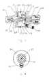
- FIG. 1is a schematic isometric external view of an exemplary embodiment of the invention, a coaxial ring circuit assembly in the form of an in-line DC Bias injector and surge suppressor.
- FIG. 2is a schematic isometric exploded view of FIG. 1 , the second portion shown in cross-section for clarity.
- FIG. 3is a schematic side cross-section view of the assembly of FIG. 1 , the PCB and electrical components thereon shown in side view for clarity.
- FIG. 4is a schematic end view of the second portion of FIG. 1 .
- FIG. 5is a schematic isometric external view of an alternative embodiment of the invention.
- FIG. 6is a schematic side cross-section view of the assembly of FIG. 5 .
- a coaxial ring circuit assembly 1has a printed circuit board (PCB) 3 positioned in a perpendicular (normal) orientation with respect to a longitudinal axis of the assembly 1 .
- the PCB 3is seated within an enclosed cylindrical PCB chamber 5 surrounding an outer conductor sleeve 7 section.
- the assembly 1is composed of a first portion 9 and a second portion 111 adapted to couple together, for example via thread(s) 13 formed in corresponding overlapping sections of an outer wall 15 of each portion.
- a sealing gasketsuch as an o-ring 17 may be applied between the overlapping section(s) to environmentally seal the assembly 1 .
- the first and second portion(s) 9 , 11may be adapted for permanent interconnection via a friction fit between the overlapping sections of the outer wall 15 .
- the outer conductor sleeve 7 section(s)extend generally between a first connection interface 19 of the first portion 9 and a second connection interface 21 of the second portion 11 .
- a diameter along the outer conductor sleeve 7 section(s)may be selected to seat insulator(s) 23 and or minimize an impedance discontinuity that may occur between the assembly 1 and upstream and or downstream coaxial cable that the assembly 1 will be coupled in-line with.
- the respective outer conductor sleeve 7 section(s) of the first and second portion(s) 9 , 11may be adapted to bottom against each other in secure electrical connection as the thread(s) 13 or other retaining arrangement formed along the outer wall(s) 15 are fully engaged.
- the first portion 9 and second portion 11also each support an inner conductor 25 positioned coaxially within the outer conductor sleeve 7 section by one or more insulator(s) 23 .
- the inner conductor 25 of each portionis adapted to mate together as the first and second portion(s) 9 , 11 are coupled, for example via a pin 27 into spring finger 29 configuration.
- a dielectric spacersuch as a dielectric sleeve 31 may be installed between the pin 27 and spring finger(s) 29 or other connection between the inner conductor 25 of each portion.
- the dielectric spacermay be alternatively formed as an air gap, dielectric coating or the like which provides a direct current break in the inner conductor 25 but capacitively couples higher frequencies via a capacitive coupling configurable via the thickness and or dielectric properties of the selected dielectric material.
- the dielectric spacer or other form of DC breakmay be omitted and or permanently formed in the inner conductor so that a single inner conductor 25 element extends between the first connection interface 19 and the second connection interface 21 .
- a coupling conductor 35passes from the PCB 3 , through the slot 33 and is coupled to the inner conductor 25 for example via a butt solder joint and or insertion into a corresponding hole 35 formed in the inner conductor 25 .
- the PCB 3may be formed with contact surface(s) 37 , for example about connection hole(s) 39 , for coupling with the outer conductor and or a grounding connection about the bottom of the PCB chamber 5 .
- connection(s) 39may be coupled with one or more inputs and or output port(s) 43 formed in the first and or second portion(s) 9 , 11 .
- the port(s) 43may be used, for example, to supply a DC bias current to the PCB 3 or as a signal tap output.
- the port(s) 43may be arranged at an angle with respect to the longitudinal axis of the assembly 1 .
- the PCB 3may be formed in a ring configuration. Alternatively, a portion of a ring such as a U shaped portion may be applied.
- the maximum dimensions of the PCB 3are determined by the differential between the selected diameters of the outer conductor sleeve 7 section(s) and the outer wall 15 .
- the PCB chamber 5is also dimensioned longitudinally to accommodate the expected height of any PCB 3 mounted electrical components such as inductors, capacitors and or metal oxide varistors.
- a PCB 3may be applied at both ends of the PCB chamber 5 and or the desired electrical components may be mounted to both sides of a PCB 3 .
- First and second electrical connection interface(s) 19 , 21 at corresponding ends of the first and second portion(s) 9 , 11may be selected from standardized and or proprietary configurations according to the expected interface requirements of the assembly 1 .
- FIGS. 1–4demonstrate first and second connection interface(s) formed as male and female Type N connectors while FIGS. 5 and 6 show a 7/16 DIN connector interface.
- any desired connector interface with selected male and or female configurationmay be applied, including first and second connection interface(s) 19 , 21 adapted to accept raw cable ends.
- the ring shaped PCB chamber 5 and perpendicular (normal) orientation of the PCB 3 thereinallows a majority of the first and second portion 9 , 11 features to be cast and or machined along a single central turning axis, greatly simplifying the machine tool equipment requirements and number of tool station mounting operations that are required during manufacture. Further, the separate cover, environmental seal and cover retaining hardware found in prior off-axis rectangular PCB chamber configurations has been eliminated.
Landscapes
- Life Sciences & Earth Sciences (AREA)
- Pest Control & Pesticides (AREA)
- Engineering & Computer Science (AREA)
- Insects & Arthropods (AREA)
- Wood Science & Technology (AREA)
- Zoology (AREA)
- Environmental Sciences (AREA)
- Coupling Device And Connection With Printed Circuit (AREA)
- Manufacturing Of Electrical Connectors (AREA)
Abstract
Description
| 1 | assembly |
| 3 | printed circuit board |
| 5 | |
| 7 | |
| 9 | |
| 11 | |
| 13 | |
| 15 | outer wall |
| 17 | o- |
| 19 | |
| 21 | |
| 23 | |
| 25 | |
| 27 | |
| 29 | |
| 31 | |
| 33 | |
| 35 | |
| 37 | |
| 39 | |
| 41 | |
| 43 | port |
Claims (17)
Priority Applications (8)
| Application Number | Priority Date | Filing Date | Title |
|---|---|---|---|
| US10/908,253US7094104B1 (en) | 2005-05-04 | 2005-05-04 | In-line coaxial circuit assembly |
| KR1020060016051AKR20060115330A (en) | 2005-05-04 | 2006-02-20 | Inline coaxial circuit assembly |
| DE602006017469TDE602006017469D1 (en) | 2005-05-04 | 2006-02-21 | Coaxial connection with an integrated circuit arrangement |
| EP06110200AEP1720212B1 (en) | 2005-05-04 | 2006-02-21 | In-line coaxial circuit assembly |
| AT06110200TATE484864T1 (en) | 2005-05-04 | 2006-02-21 | COAXIAL CONNECTION WITH AN INTEGRATED CIRCUIT ARRANGEMENT |
| BRPI0600849-6ABRPI0600849A (en) | 2005-05-04 | 2006-03-24 | coaxial in-line circuitry and method for manufacturing it |
| TW095113259ATW200640085A (en) | 2005-05-04 | 2006-04-14 | In-line coaxial circuit assembly and method of manufacturing the same |
| CNB2006100748821ACN100508304C (en) | 2005-05-04 | 2006-04-25 | Series coaxial circuit assembly and method of manufacturing the same |
Applications Claiming Priority (1)
| Application Number | Priority Date | Filing Date | Title |
|---|---|---|---|
| US10/908,253US7094104B1 (en) | 2005-05-04 | 2005-05-04 | In-line coaxial circuit assembly |
Publications (1)
| Publication Number | Publication Date |
|---|---|
| US7094104B1true US7094104B1 (en) | 2006-08-22 |
Family
ID=36283888
Family Applications (1)
| Application Number | Title | Priority Date | Filing Date |
|---|---|---|---|
| US10/908,253Expired - LifetimeUS7094104B1 (en) | 2005-05-04 | 2005-05-04 | In-line coaxial circuit assembly |
Country Status (8)
| Country | Link |
|---|---|
| US (1) | US7094104B1 (en) |
| EP (1) | EP1720212B1 (en) |
| KR (1) | KR20060115330A (en) |
| CN (1) | CN100508304C (en) |
| AT (1) | ATE484864T1 (en) |
| BR (1) | BRPI0600849A (en) |
| DE (1) | DE602006017469D1 (en) |
| TW (1) | TW200640085A (en) |
Cited By (33)
| Publication number | Priority date | Publication date | Assignee | Title |
|---|---|---|---|---|
| EP1901404A2 (en) | 2006-09-15 | 2008-03-19 | Delphi Technologies, Inc. | Filtered electrical connector and combination having same |
| US20080170346A1 (en)* | 2007-01-17 | 2008-07-17 | Andrew Corporation | Folded Surface Capacitor In-line Assembly |
| US20090195956A1 (en)* | 2008-01-31 | 2009-08-06 | Commscope, Inc. Of North Carolina | Low Bypass Fine Arrestor |
| US20090278622A1 (en)* | 2008-05-12 | 2009-11-12 | Andrew Llc | Coaxial Impedance Matching Adapter and Method of Manufacture |
| US20090305531A1 (en)* | 2008-06-04 | 2009-12-10 | Hong Fu Jin Precision Industry (Shenzhen) Co., Ltd . | Cable connector |
| US20100022118A1 (en)* | 2008-07-24 | 2010-01-28 | Hon Hai Precision Industry Co., Ltd. | Power connector having an imporved internal printed circuit board |
| WO2010057735A3 (en)* | 2008-11-19 | 2010-07-29 | Weidmüller Interface GmbH & Co. KG | Round plug connector |
| US20110077884A1 (en)* | 2008-11-17 | 2011-03-31 | Rochester Institute Of Technology | Internal coaxial cable connector integrated circuit and method of use thereof |
| US20110080057A1 (en)* | 2008-11-17 | 2011-04-07 | Rochester Institute Of Technology | Power harvesting device and method of use thereof |
| US20110080158A1 (en)* | 2007-09-24 | 2011-04-07 | John Mezzalingua Associates, Inc. | Coaxial cable connector with internal floating ground circuitry and method of use thereof |
| US20110111629A1 (en)* | 2009-11-10 | 2011-05-12 | Hon Hai Precision Industry Co., Ltd. | Cable assembly having grounding means |
| US20110124220A1 (en)* | 2009-11-24 | 2011-05-26 | Hon Hai Precision Industry Co., Ltd. | Cable connector assembly with improved printed circuit board |
| US20110130034A1 (en)* | 2008-11-17 | 2011-06-02 | John Mezzalingua Associates Inc. | Coaxial connector with integrated molded substrate and method of use thereof |
| US20110161050A1 (en)* | 2009-12-03 | 2011-06-30 | John Mezzalingua Associates, Inc. | Coaxial cable connector parameter monitoring system |
| US20110256769A1 (en)* | 2010-04-19 | 2011-10-20 | Hon Hai Precision Industry Co., Ltd. | Cable assembly having indicating device |
| US20110294327A1 (en)* | 2009-12-11 | 2011-12-01 | Aerovironment , Inc. | Waterproof electrical connector and system |
| US20130040504A1 (en)* | 2011-08-11 | 2013-02-14 | Sumitomo Wiring Systems, Ltd. | Connector with electric component |
| US8456789B2 (en) | 2010-12-15 | 2013-06-04 | Andrew Llc | Tunable coaxial surge arrestor |
| US8604936B2 (en) | 2010-12-13 | 2013-12-10 | Ppc Broadband, Inc. | Coaxial cable connector, system and method of use thereof |
| US8622768B2 (en) | 2010-11-22 | 2014-01-07 | Andrew Llc | Connector with capacitively coupled connector interface |
| US8622762B2 (en) | 2010-11-22 | 2014-01-07 | Andrew Llc | Blind mate capacitively coupled connector |
| US8773255B2 (en) | 2007-09-24 | 2014-07-08 | Ppc Broadband, Inc. | Status sensing and reporting interface |
| US8858262B2 (en)* | 2012-12-04 | 2014-10-14 | Genesis Technology Usa, Inc. | F-connector with integrated surge protection |
| US8894439B2 (en) | 2010-11-22 | 2014-11-25 | Andrew Llc | Capacitivly coupled flat conductor connector |
| EP2843775A1 (en)* | 2013-08-28 | 2015-03-04 | Spinner GmbH | U-link connector for RF signals with integrated bias circuit |
| US9048527B2 (en) | 2012-11-09 | 2015-06-02 | Commscope Technologies Llc | Coaxial connector with capacitively coupled connector interface and method of manufacture |
| WO2017165786A1 (en)* | 2016-03-24 | 2017-09-28 | Ppc Broadband, Inc. | Mini isolator |
| US9831617B1 (en)* | 2016-05-31 | 2017-11-28 | Acbel Polytech Inc. | Filtered connector and filter board thereof |
| US10270202B2 (en)* | 2017-05-16 | 2019-04-23 | Semikron Elektronik Gmbh & Co. Kg | Power electronic arrangement comprising a communication device |
| US20190288463A1 (en)* | 2018-03-14 | 2019-09-19 | Commscope Technologies Llc | Coaxial bias t-connector |
| US10530072B2 (en) | 2015-10-09 | 2020-01-07 | Ppc Broadband, Inc. | Mini isolator |
| US10811749B2 (en) | 2015-10-09 | 2020-10-20 | Ppc Broadband, Inc. | Mini isolator |
| US20220416389A1 (en)* | 2021-06-29 | 2022-12-29 | Ezconn Corporation | Coaxial isolator |
Families Citing this family (2)
| Publication number | Priority date | Publication date | Assignee | Title |
|---|---|---|---|---|
| CN109390783A (en)* | 2017-08-03 | 2019-02-26 | 定逸工业股份有限公司 | Network cable electric connector |
| EP3881397B1 (en)* | 2018-11-12 | 2024-03-06 | Huber+Suhner Ag | Printed circuit board connector |
Citations (20)
| Publication number | Priority date | Publication date | Assignee | Title |
|---|---|---|---|---|
| US3320557A (en)* | 1963-04-02 | 1967-05-16 | Globe Union Inc | Feed-through capacitor |
| US3750053A (en) | 1972-04-24 | 1973-07-31 | Plessey Inc | Coaxial transmission line rf switch |
| US4187481A (en)* | 1977-12-23 | 1980-02-05 | Bunker Ramo Corporation | EMI Filter connector having RF suppression characteristics |
| US4262317A (en) | 1979-03-22 | 1981-04-14 | Reliable Electric Company | Line protector for a communications circuit |
| US4359764A (en) | 1980-04-08 | 1982-11-16 | Block Roger R | Connector for electromagnetic impulse suppression |
| US4554608A (en) | 1982-11-15 | 1985-11-19 | Block Roger R | Connector for electromagnetic impulse suppression |
| US5060108A (en)* | 1990-01-25 | 1991-10-22 | Texas Instruments Incorporated | Packaging and sealing for pressure transducer |
| US5278525A (en)* | 1992-06-11 | 1994-01-11 | John Mezzalingua Assoc. Inc. | Electrical filter with multiple filter sections |
| US5329262A (en)* | 1991-06-24 | 1994-07-12 | The Whitaker Corporation | Fixed RF connector having internal floating members with impedance compensation |
| US5953195A (en) | 1997-02-26 | 1999-09-14 | Reltec Corporation | Coaxial protector |
| US5982602A (en) | 1993-10-07 | 1999-11-09 | Andrew Corporation | Surge protector connector |
| US6236551B1 (en) | 1997-10-14 | 2001-05-22 | Polyphaser Corporation | Surge suppressor device |
| US6294740B1 (en) | 1999-09-20 | 2001-09-25 | Andrew Corporation | Spring clip for a gas tube surge arrestor |
| US6452773B1 (en) | 2000-03-21 | 2002-09-17 | Andrew Corporation | Broadband shorted stub surge protector |
| US6529357B1 (en) | 1999-08-05 | 2003-03-04 | Spinner Gmbh Elektrotechnische Fabrik | Coaxial overvoltage protector with improved inner conductor of the λ/4 short-circuit line |
| US6636407B1 (en) | 2000-09-13 | 2003-10-21 | Andrew Corporation | Broadband surge protector for RF/DC carrying conductor |
| US6636408B2 (en) | 2001-03-26 | 2003-10-21 | Marconi Communications, Inc. | Coaxial transmission line surge protector assembly with an integral fuse link |
| US6688916B1 (en) | 2002-12-23 | 2004-02-10 | Chun Te Lee | Signal connector having function of abrupt wave protection |
| US6721155B2 (en) | 2001-08-23 | 2004-04-13 | Andrew Corp. | Broadband surge protector with stub DC injection |
| US6785110B2 (en) | 2001-10-12 | 2004-08-31 | Polyphaser Corporation | Rf surge protection device |
Family Cites Families (4)
| Publication number | Priority date | Publication date | Assignee | Title |
|---|---|---|---|---|
| US576782A (en)* | 1897-02-09 | Removable support for ash-receptacles | ||
| JPS5130421B1 (en)* | 1965-09-30 | 1976-09-01 | ||
| US6317307B1 (en) | 1998-10-07 | 2001-11-13 | Siecor Operations, Llc | Coaxial fuse and protector |
| WO2002103875A1 (en)* | 2001-06-15 | 2002-12-27 | Kauffman George M | Protective device |
- 2005
- 2005-05-04USUS10/908,253patent/US7094104B1/ennot_activeExpired - Lifetime
- 2006
- 2006-02-20KRKR1020060016051Apatent/KR20060115330A/ennot_activeCeased
- 2006-02-21DEDE602006017469Tpatent/DE602006017469D1/enactiveActive
- 2006-02-21EPEP06110200Apatent/EP1720212B1/ennot_activeNot-in-force
- 2006-02-21ATAT06110200Tpatent/ATE484864T1/ennot_activeIP Right Cessation
- 2006-03-24BRBRPI0600849-6Apatent/BRPI0600849A/ennot_activeIP Right Cessation
- 2006-04-14TWTW095113259Apatent/TW200640085A/enunknown
- 2006-04-25CNCNB2006100748821Apatent/CN100508304C/ennot_activeExpired - Fee Related
Patent Citations (20)
| Publication number | Priority date | Publication date | Assignee | Title |
|---|---|---|---|---|
| US3320557A (en)* | 1963-04-02 | 1967-05-16 | Globe Union Inc | Feed-through capacitor |
| US3750053A (en) | 1972-04-24 | 1973-07-31 | Plessey Inc | Coaxial transmission line rf switch |
| US4187481A (en)* | 1977-12-23 | 1980-02-05 | Bunker Ramo Corporation | EMI Filter connector having RF suppression characteristics |
| US4262317A (en) | 1979-03-22 | 1981-04-14 | Reliable Electric Company | Line protector for a communications circuit |
| US4359764A (en) | 1980-04-08 | 1982-11-16 | Block Roger R | Connector for electromagnetic impulse suppression |
| US4554608A (en) | 1982-11-15 | 1985-11-19 | Block Roger R | Connector for electromagnetic impulse suppression |
| US5060108A (en)* | 1990-01-25 | 1991-10-22 | Texas Instruments Incorporated | Packaging and sealing for pressure transducer |
| US5329262A (en)* | 1991-06-24 | 1994-07-12 | The Whitaker Corporation | Fixed RF connector having internal floating members with impedance compensation |
| US5278525A (en)* | 1992-06-11 | 1994-01-11 | John Mezzalingua Assoc. Inc. | Electrical filter with multiple filter sections |
| US5982602A (en) | 1993-10-07 | 1999-11-09 | Andrew Corporation | Surge protector connector |
| US5953195A (en) | 1997-02-26 | 1999-09-14 | Reltec Corporation | Coaxial protector |
| US6236551B1 (en) | 1997-10-14 | 2001-05-22 | Polyphaser Corporation | Surge suppressor device |
| US6529357B1 (en) | 1999-08-05 | 2003-03-04 | Spinner Gmbh Elektrotechnische Fabrik | Coaxial overvoltage protector with improved inner conductor of the λ/4 short-circuit line |
| US6294740B1 (en) | 1999-09-20 | 2001-09-25 | Andrew Corporation | Spring clip for a gas tube surge arrestor |
| US6452773B1 (en) | 2000-03-21 | 2002-09-17 | Andrew Corporation | Broadband shorted stub surge protector |
| US6636407B1 (en) | 2000-09-13 | 2003-10-21 | Andrew Corporation | Broadband surge protector for RF/DC carrying conductor |
| US6636408B2 (en) | 2001-03-26 | 2003-10-21 | Marconi Communications, Inc. | Coaxial transmission line surge protector assembly with an integral fuse link |
| US6721155B2 (en) | 2001-08-23 | 2004-04-13 | Andrew Corp. | Broadband surge protector with stub DC injection |
| US6785110B2 (en) | 2001-10-12 | 2004-08-31 | Polyphaser Corporation | Rf surge protection device |
| US6688916B1 (en) | 2002-12-23 | 2004-02-10 | Chun Te Lee | Signal connector having function of abrupt wave protection |
Cited By (63)
| Publication number | Priority date | Publication date | Assignee | Title |
|---|---|---|---|---|
| US20080070444A1 (en)* | 2006-09-15 | 2008-03-20 | Blasko Raymond J | Filtered electrical connector and combination having same |
| EP1901404A2 (en) | 2006-09-15 | 2008-03-19 | Delphi Technologies, Inc. | Filtered electrical connector and combination having same |
| US7588466B2 (en) | 2006-09-15 | 2009-09-15 | Delphi Technologies, Inc. | Filtered electrical connector and combination having same |
| EP1901404A3 (en)* | 2006-09-15 | 2009-11-11 | Delphi Technologies, Inc. | Filtered electrical connector and combination having same |
| US8174132B2 (en)* | 2007-01-17 | 2012-05-08 | Andrew Llc | Folded surface capacitor in-line assembly |
| US20080170346A1 (en)* | 2007-01-17 | 2008-07-17 | Andrew Corporation | Folded Surface Capacitor In-line Assembly |
| US20110080158A1 (en)* | 2007-09-24 | 2011-04-07 | John Mezzalingua Associates, Inc. | Coaxial cable connector with internal floating ground circuitry and method of use thereof |
| US8570178B2 (en) | 2007-09-24 | 2013-10-29 | Ppc Broadband, Inc. | Coaxial cable connector with internal floating ground circuitry and method of use thereof |
| US8773255B2 (en) | 2007-09-24 | 2014-07-08 | Ppc Broadband, Inc. | Status sensing and reporting interface |
| US20090195956A1 (en)* | 2008-01-31 | 2009-08-06 | Commscope, Inc. Of North Carolina | Low Bypass Fine Arrestor |
| US7623332B2 (en) | 2008-01-31 | 2009-11-24 | Commscope, Inc. Of North Carolina | Low bypass fine arrestor |
| US8164877B2 (en)* | 2008-01-31 | 2012-04-24 | Andrew Llc | Coaxial in-line assembly |
| US20100027181A1 (en)* | 2008-01-31 | 2010-02-04 | Commscope, Inc. Of North Carolina | Coaxial In-Line Assembly |
| US8643996B2 (en) | 2008-01-31 | 2014-02-04 | Andrew Llc | Coaxial in-line assembly |
| US7898357B2 (en) | 2008-05-12 | 2011-03-01 | Andrew Llc | Coaxial impedance matching adapter and method of manufacture |
| EP2120282A1 (en)* | 2008-05-12 | 2009-11-18 | Andrew LLC | Coaxial impedance matching adapter and method of manufacture |
| US20090278622A1 (en)* | 2008-05-12 | 2009-11-12 | Andrew Llc | Coaxial Impedance Matching Adapter and Method of Manufacture |
| US7674116B2 (en)* | 2008-06-04 | 2010-03-09 | Hong Fu Jin Precision Industry (Shenzhen) Co., Ltd. | Cable connector |
| US20090305531A1 (en)* | 2008-06-04 | 2009-12-10 | Hong Fu Jin Precision Industry (Shenzhen) Co., Ltd . | Cable connector |
| US7789675B2 (en)* | 2008-07-24 | 2010-09-07 | Hon Hai Precision Ind. Co., Ltd. | Power connector having an improved internal printed circuit board |
| US20100022118A1 (en)* | 2008-07-24 | 2010-01-28 | Hon Hai Precision Industry Co., Ltd. | Power connector having an imporved internal printed circuit board |
| US8414326B2 (en)* | 2008-11-17 | 2013-04-09 | Rochester Institute Of Technology | Internal coaxial cable connector integrated circuit and method of use thereof |
| US20110077884A1 (en)* | 2008-11-17 | 2011-03-31 | Rochester Institute Of Technology | Internal coaxial cable connector integrated circuit and method of use thereof |
| US20110080057A1 (en)* | 2008-11-17 | 2011-04-07 | Rochester Institute Of Technology | Power harvesting device and method of use thereof |
| US8419464B2 (en)* | 2008-11-17 | 2013-04-16 | Ppc Broadband, Inc. | Coaxial connector with integrated molded substrate and method of use thereof |
| US8376774B2 (en) | 2008-11-17 | 2013-02-19 | Rochester Institute Of Technology | Power extracting device and method of use thereof |
| US20110130034A1 (en)* | 2008-11-17 | 2011-06-02 | John Mezzalingua Associates Inc. | Coaxial connector with integrated molded substrate and method of use thereof |
| WO2010057735A3 (en)* | 2008-11-19 | 2010-07-29 | Weidmüller Interface GmbH & Co. KG | Round plug connector |
| US8430692B2 (en)* | 2009-11-10 | 2013-04-30 | Hon Hai Precision Ind. Co., Ltd. | Cable assembly having grounding means |
| US20110111629A1 (en)* | 2009-11-10 | 2011-05-12 | Hon Hai Precision Industry Co., Ltd. | Cable assembly having grounding means |
| US20110124220A1 (en)* | 2009-11-24 | 2011-05-26 | Hon Hai Precision Industry Co., Ltd. | Cable connector assembly with improved printed circuit board |
| US8124496B2 (en)* | 2009-11-24 | 2012-02-28 | Hon Hai Precision Ind. Co., Ltd. | Cable connector assembly with improved printed circuit board |
| US8618944B2 (en) | 2009-12-03 | 2013-12-31 | Ppc Broadband, Inc. | Coaxial cable connector parameter monitoring system |
| US20110161050A1 (en)* | 2009-12-03 | 2011-06-30 | John Mezzalingua Associates, Inc. | Coaxial cable connector parameter monitoring system |
| US20110294327A1 (en)* | 2009-12-11 | 2011-12-01 | Aerovironment , Inc. | Waterproof electrical connector and system |
| US8491336B2 (en)* | 2009-12-11 | 2013-07-23 | Aerovironment, Inc. | Waterproof electrical connector and system |
| US8257113B2 (en)* | 2009-12-11 | 2012-09-04 | Aerovironment, Inc. | Waterproof electrical connector and system |
| US8475203B2 (en)* | 2010-04-19 | 2013-07-02 | Hon Hai Precision Industry Co., Ltd. | Cable assembly having indicating device |
| US20110256769A1 (en)* | 2010-04-19 | 2011-10-20 | Hon Hai Precision Industry Co., Ltd. | Cable assembly having indicating device |
| US8894439B2 (en) | 2010-11-22 | 2014-11-25 | Andrew Llc | Capacitivly coupled flat conductor connector |
| US8622768B2 (en) | 2010-11-22 | 2014-01-07 | Andrew Llc | Connector with capacitively coupled connector interface |
| US8622762B2 (en) | 2010-11-22 | 2014-01-07 | Andrew Llc | Blind mate capacitively coupled connector |
| US8604936B2 (en) | 2010-12-13 | 2013-12-10 | Ppc Broadband, Inc. | Coaxial cable connector, system and method of use thereof |
| US8456789B2 (en) | 2010-12-15 | 2013-06-04 | Andrew Llc | Tunable coaxial surge arrestor |
| US8870599B2 (en)* | 2011-08-11 | 2014-10-28 | Sumitomo Wiring Systems, Ltd. | Connector with electric component |
| US20130040504A1 (en)* | 2011-08-11 | 2013-02-14 | Sumitomo Wiring Systems, Ltd. | Connector with electric component |
| US9048527B2 (en) | 2012-11-09 | 2015-06-02 | Commscope Technologies Llc | Coaxial connector with capacitively coupled connector interface and method of manufacture |
| US8858262B2 (en)* | 2012-12-04 | 2014-10-14 | Genesis Technology Usa, Inc. | F-connector with integrated surge protection |
| EP2843775A1 (en)* | 2013-08-28 | 2015-03-04 | Spinner GmbH | U-link connector for RF signals with integrated bias circuit |
| EP2843776A3 (en)* | 2013-08-28 | 2015-03-18 | Spinner GmbH | U-link connector for RF signals with integrated bias circuit |
| US10530072B2 (en) | 2015-10-09 | 2020-01-07 | Ppc Broadband, Inc. | Mini isolator |
| US10868373B2 (en) | 2015-10-09 | 2020-12-15 | Ppc Broadband, Inc. | Mini isolator |
| US10811749B2 (en) | 2015-10-09 | 2020-10-20 | Ppc Broadband, Inc. | Mini isolator |
| WO2017165786A1 (en)* | 2016-03-24 | 2017-09-28 | Ppc Broadband, Inc. | Mini isolator |
| US9831617B1 (en)* | 2016-05-31 | 2017-11-28 | Acbel Polytech Inc. | Filtered connector and filter board thereof |
| US20170346243A1 (en)* | 2016-05-31 | 2017-11-30 | Acbel Polytech Inc. | Filtered connector and filter board thereof |
| US10270202B2 (en)* | 2017-05-16 | 2019-04-23 | Semikron Elektronik Gmbh & Co. Kg | Power electronic arrangement comprising a communication device |
| US10666000B2 (en)* | 2018-03-14 | 2020-05-26 | Commscope Technologies Llc | Coaxial bias T-connector |
| CN110277704A (en)* | 2018-03-14 | 2019-09-24 | 康普技术有限责任公司 | coaxial offset T-shaped connector |
| US20190288463A1 (en)* | 2018-03-14 | 2019-09-19 | Commscope Technologies Llc | Coaxial bias t-connector |
| CN110277704B (en)* | 2018-03-14 | 2022-12-09 | 康普技术有限责任公司 | Coaxial Offset T Connector |
| US20220416389A1 (en)* | 2021-06-29 | 2022-12-29 | Ezconn Corporation | Coaxial isolator |
| US12206151B2 (en)* | 2021-06-29 | 2025-01-21 | Ezconn Corporation | Coaxial isolator |
Also Published As
| Publication number | Publication date |
|---|---|
| KR20060115330A (en) | 2006-11-08 |
| EP1720212B1 (en) | 2010-10-13 |
| CN1870356A (en) | 2006-11-29 |
| ATE484864T1 (en) | 2010-10-15 |
| TW200640085A (en) | 2006-11-16 |
| CN100508304C (en) | 2009-07-01 |
| EP1720212A1 (en) | 2006-11-08 |
| BRPI0600849A (en) | 2006-12-19 |
| DE602006017469D1 (en) | 2010-11-25 |
Similar Documents
| Publication | Publication Date | Title |
|---|---|---|
| US7094104B1 (en) | In-line coaxial circuit assembly | |
| US20200411939A1 (en) | Mini isolator | |
| EP2088652B1 (en) | Low bypass fine arrestor | |
| US7306484B1 (en) | Coax-to-power adapter | |
| US6674343B2 (en) | Electronic filter assembly | |
| US10868373B2 (en) | Mini isolator | |
| EP1441419A2 (en) | Float mount coaxial connector | |
| EP1067637A2 (en) | Coaxial connector with integral electronic components | |
| US20180316103A1 (en) | Multi-pin connector block assembly | |
| EP2962368A1 (en) | Coaxial cable and connector with capacitive coupling | |
| US10666000B2 (en) | Coaxial bias T-connector | |
| TWI608674B (en) | Signal transfering device and adapter assembly | |
| US6269162B1 (en) | Telecommunications cross-connect assembly with combined connector/transformer | |
| EP0696088A1 (en) | Filter assemblies | |
| KR20230087173A (en) | Contact unit for filter connector and cable assembly comprising the same | |
| CN208093889U (en) | Coaxial offset T-type connector | |
| US20240324097A1 (en) | Impedance matched via connections in a printed circuit board | |
| CN219554084U (en) | EMC cover plate connector | |
| CN222868251U (en) | A connector capable of resisting electromagnetic interference | |
| WO2017165786A1 (en) | Mini isolator | |
| EP3616267A1 (en) | Radio frequency (rf) connector pin assembly | |
| KR20230087175A (en) | Contact unit for filter connector and cable assembly comprising the same | |
| WO2016074882A1 (en) | Dielectric coupling sleeve | |
| GB2292030A (en) | Filtered connectors | |
| BR112018006943B1 (en) | INSULATOR |
Legal Events
| Date | Code | Title | Description |
|---|---|---|---|
| AS | Assignment | Owner name:ANDREW CORPORATION, ILLINOIS Free format text:ASSIGNMENT OF ASSIGNORS INTEREST;ASSIGNORS:BURKE, RODGER;VAN SWEARINGEN, KENDRICK;LEE, JOON;AND OTHERS;REEL/FRAME:015973/0107 Effective date:20050503 | |
| STCF | Information on status: patent grant | Free format text:PATENTED CASE | |
| AS | Assignment | Owner name:BANK OF AMERICA, N.A., AS ADMINISTRATIVE AGENT, CA Free format text:SECURITY AGREEMENT;ASSIGNORS:COMMSCOPE, INC. OF NORTH CAROLINA;ALLEN TELECOM, LLC;ANDREW CORPORATION;REEL/FRAME:020362/0241 Effective date:20071227 Owner name:BANK OF AMERICA, N.A., AS ADMINISTRATIVE AGENT,CAL Free format text:SECURITY AGREEMENT;ASSIGNORS:COMMSCOPE, INC. OF NORTH CAROLINA;ALLEN TELECOM, LLC;ANDREW CORPORATION;REEL/FRAME:020362/0241 Effective date:20071227 | |
| AS | Assignment | Owner name:ANDREW LLC, NORTH CAROLINA Free format text:CHANGE OF NAME;ASSIGNOR:ANDREW CORPORATION;REEL/FRAME:021805/0276 Effective date:20080827 | |
| FPAY | Fee payment | Year of fee payment:4 | |
| AS | Assignment | Owner name:ANDREW LLC (F/K/A ANDREW CORPORATION), NORTH CAROL Free format text:PATENT RELEASE;ASSIGNOR:BANK OF AMERICA, N.A., AS ADMINISTRATIVE AGENT;REEL/FRAME:026039/0005 Effective date:20110114 Owner name:ALLEN TELECOM LLC, NORTH CAROLINA Free format text:PATENT RELEASE;ASSIGNOR:BANK OF AMERICA, N.A., AS ADMINISTRATIVE AGENT;REEL/FRAME:026039/0005 Effective date:20110114 Owner name:COMMSCOPE, INC. OF NORTH CAROLINA, NORTH CAROLINA Free format text:PATENT RELEASE;ASSIGNOR:BANK OF AMERICA, N.A., AS ADMINISTRATIVE AGENT;REEL/FRAME:026039/0005 Effective date:20110114 | |
| AS | Assignment | Owner name:JPMORGAN CHASE BANK, N.A., AS COLLATERAL AGENT, NE Free format text:SECURITY AGREEMENT;ASSIGNORS:ALLEN TELECOM LLC, A DELAWARE LLC;ANDREW LLC, A DELAWARE LLC;COMMSCOPE, INC. OF NORTH CAROLINA, A NORTH CAROLINA CORPORATION;REEL/FRAME:026276/0363 Effective date:20110114 | |
| AS | Assignment | Owner name:JPMORGAN CHASE BANK, N.A., AS COLLATERAL AGENT, NE Free format text:SECURITY AGREEMENT;ASSIGNORS:ALLEN TELECOM LLC, A DELAWARE LLC;ANDREW LLC, A DELAWARE LLC;COMMSCOPE, INC OF NORTH CAROLINA, A NORTH CAROLINA CORPORATION;REEL/FRAME:026272/0543 Effective date:20110114 | |
| FPAY | Fee payment | Year of fee payment:8 | |
| AS | Assignment | Owner name:COMMSCOPE TECHNOLOGIES LLC, NORTH CAROLINA Free format text:CHANGE OF NAME;ASSIGNOR:ANDREW LLC;REEL/FRAME:035283/0849 Effective date:20150301 | |
| AS | Assignment | Owner name:WILMINGTON TRUST, NATIONAL ASSOCIATION, AS COLLATERAL AGENT, CONNECTICUT Free format text:SECURITY INTEREST;ASSIGNORS:ALLEN TELECOM LLC;COMMSCOPE TECHNOLOGIES LLC;COMMSCOPE, INC. OF NORTH CAROLINA;AND OTHERS;REEL/FRAME:036201/0283 Effective date:20150611 Owner name:WILMINGTON TRUST, NATIONAL ASSOCIATION, AS COLLATE Free format text:SECURITY INTEREST;ASSIGNORS:ALLEN TELECOM LLC;COMMSCOPE TECHNOLOGIES LLC;COMMSCOPE, INC. OF NORTH CAROLINA;AND OTHERS;REEL/FRAME:036201/0283 Effective date:20150611 | |
| AS | Assignment | Owner name:ALLEN TELECOM LLC, NORTH CAROLINA Free format text:RELEASE OF SECURITY INTEREST PATENTS (RELEASES RF 036201/0283);ASSIGNOR:WILMINGTON TRUST, NATIONAL ASSOCIATION;REEL/FRAME:042126/0434 Effective date:20170317 Owner name:COMMSCOPE, INC. OF NORTH CAROLINA, NORTH CAROLINA Free format text:RELEASE OF SECURITY INTEREST PATENTS (RELEASES RF 036201/0283);ASSIGNOR:WILMINGTON TRUST, NATIONAL ASSOCIATION;REEL/FRAME:042126/0434 Effective date:20170317 Owner name:REDWOOD SYSTEMS, INC., NORTH CAROLINA Free format text:RELEASE OF SECURITY INTEREST PATENTS (RELEASES RF 036201/0283);ASSIGNOR:WILMINGTON TRUST, NATIONAL ASSOCIATION;REEL/FRAME:042126/0434 Effective date:20170317 Owner name:COMMSCOPE TECHNOLOGIES LLC, NORTH CAROLINA Free format text:RELEASE OF SECURITY INTEREST PATENTS (RELEASES RF 036201/0283);ASSIGNOR:WILMINGTON TRUST, NATIONAL ASSOCIATION;REEL/FRAME:042126/0434 Effective date:20170317 | |
| MAFP | Maintenance fee payment | Free format text:PAYMENT OF MAINTENANCE FEE, 12TH YEAR, LARGE ENTITY (ORIGINAL EVENT CODE: M1553) Year of fee payment:12 | |
| AS | Assignment | Owner name:ANDREW LLC, NORTH CAROLINA Free format text:CORRECTIVE ASSIGNMENT TO CORRECT THE DELETE THE WRONG PROPERTY NJMBER PREVIOUSLY RECORDED AT REEL: 021805 FRAME: 0276. ASSIGNOR(S) HEREBY CONFIRMS THE ASSIGNMENT;ASSIGNOR:ANDREW CORPORATION;REEL/FRAME:046377/0458 Effective date:20080827 | |
| AS | Assignment | Owner name:ANDREW LLC, NORTH CAROLINA Free format text:RELEASE BY SECURED PARTY;ASSIGNOR:JPMORGAN CHASE BANK, N.A.;REEL/FRAME:048840/0001 Effective date:20190404 Owner name:COMMSCOPE TECHNOLOGIES LLC, NORTH CAROLINA Free format text:RELEASE BY SECURED PARTY;ASSIGNOR:JPMORGAN CHASE BANK, N.A.;REEL/FRAME:048840/0001 Effective date:20190404 Owner name:COMMSCOPE, INC. OF NORTH CAROLINA, NORTH CAROLINA Free format text:RELEASE BY SECURED PARTY;ASSIGNOR:JPMORGAN CHASE BANK, N.A.;REEL/FRAME:048840/0001 Effective date:20190404 Owner name:ALLEN TELECOM LLC, ILLINOIS Free format text:RELEASE BY SECURED PARTY;ASSIGNOR:JPMORGAN CHASE BANK, N.A.;REEL/FRAME:048840/0001 Effective date:20190404 Owner name:REDWOOD SYSTEMS, INC., NORTH CAROLINA Free format text:RELEASE BY SECURED PARTY;ASSIGNOR:JPMORGAN CHASE BANK, N.A.;REEL/FRAME:048840/0001 Effective date:20190404 Owner name:ANDREW LLC, NORTH CAROLINA Free format text:RELEASE BY SECURED PARTY;ASSIGNOR:JPMORGAN CHASE BANK, N.A.;REEL/FRAME:049260/0001 Effective date:20190404 Owner name:COMMSCOPE TECHNOLOGIES LLC, NORTH CAROLINA Free format text:RELEASE BY SECURED PARTY;ASSIGNOR:JPMORGAN CHASE BANK, N.A.;REEL/FRAME:049260/0001 Effective date:20190404 Owner name:COMMSCOPE, INC. OF NORTH CAROLINA, NORTH CAROLINA Free format text:RELEASE BY SECURED PARTY;ASSIGNOR:JPMORGAN CHASE BANK, N.A.;REEL/FRAME:049260/0001 Effective date:20190404 Owner name:ALLEN TELECOM LLC, ILLINOIS Free format text:RELEASE BY SECURED PARTY;ASSIGNOR:JPMORGAN CHASE BANK, N.A.;REEL/FRAME:049260/0001 Effective date:20190404 Owner name:REDWOOD SYSTEMS, INC., NORTH CAROLINA Free format text:RELEASE BY SECURED PARTY;ASSIGNOR:JPMORGAN CHASE BANK, N.A.;REEL/FRAME:049260/0001 Effective date:20190404 | |
| AS | Assignment | Owner name:JPMORGAN CHASE BANK, N.A., NEW YORK Free format text:ABL SECURITY AGREEMENT;ASSIGNORS:COMMSCOPE, INC. OF NORTH CAROLINA;COMMSCOPE TECHNOLOGIES LLC;ARRIS ENTERPRISES LLC;AND OTHERS;REEL/FRAME:049892/0396 Effective date:20190404 Owner name:WILMINGTON TRUST, NATIONAL ASSOCIATION, AS COLLATE Free format text:PATENT SECURITY AGREEMENT;ASSIGNOR:COMMSCOPE TECHNOLOGIES LLC;REEL/FRAME:049892/0051 Effective date:20190404 Owner name:JPMORGAN CHASE BANK, N.A., NEW YORK Free format text:TERM LOAN SECURITY AGREEMENT;ASSIGNORS:COMMSCOPE, INC. OF NORTH CAROLINA;COMMSCOPE TECHNOLOGIES LLC;ARRIS ENTERPRISES LLC;AND OTHERS;REEL/FRAME:049905/0504 Effective date:20190404 Owner name:WILMINGTON TRUST, NATIONAL ASSOCIATION, AS COLLATERAL AGENT, CONNECTICUT Free format text:PATENT SECURITY AGREEMENT;ASSIGNOR:COMMSCOPE TECHNOLOGIES LLC;REEL/FRAME:049892/0051 Effective date:20190404 | |
| AS | Assignment | Owner name:WILMINGTON TRUST, DELAWARE Free format text:SECURITY INTEREST;ASSIGNORS:ARRIS SOLUTIONS, INC.;ARRIS ENTERPRISES LLC;COMMSCOPE TECHNOLOGIES LLC;AND OTHERS;REEL/FRAME:060752/0001 Effective date:20211115 | |
| AS | Assignment | Owner name:OUTDOOR WIRELESS NETWORKS LLC, NORTH CAROLINA Free format text:ASSIGNMENT OF ASSIGNORS INTEREST;ASSIGNOR:COMMSCOPE TECHNOLOGIES LLC;REEL/FRAME:068492/0826 Effective date:20240715 | |
| AS | Assignment | Owner name:JPMORGAN CHASE BANK, N.A., AS COLLATERAL AGENT, NEW YORK Free format text:PATENT SECURITY AGREEMENT (TERM);ASSIGNOR:OUTDOOR WIRELESS NETWORKS LLC;REEL/FRAME:068770/0632 Effective date:20240813 Owner name:JPMORGAN CHASE BANK, N.A., AS COLLATERAL AGENT, NEW YORK Free format text:PATENT SECURITY AGREEMENT (ABL);ASSIGNOR:OUTDOOR WIRELESS NETWORKS LLC;REEL/FRAME:068770/0460 Effective date:20240813 | |
| AS | Assignment | Owner name:APOLLO ADMINISTRATIVE AGENCY LLC, NEW YORK Free format text:SECURITY INTEREST;ASSIGNORS:ARRIS ENTERPRISES LLC;COMMSCOPE TECHNOLOGIES LLC;COMMSCOPE INC., OF NORTH CAROLINA;AND OTHERS;REEL/FRAME:069889/0114 Effective date:20241217 | |
| AS | Assignment | Owner name:OUTDOOR WIRELESS NETWORKS LLC, NORTH CAROLINA Free format text:RELEASE OF SECURITY INTEREST AT REEL/FRAME 068770/0632;ASSIGNOR:JPMORGAN CHASE BANK, N.A., AS COLLATERAL AGENT;REEL/FRAME:069743/0264 Effective date:20241217 Owner name:RUCKUS WIRELESS, LLC (F/K/A RUCKUS WIRELESS, INC.), NORTH CAROLINA Free format text:RELEASE OF SECURITY INTEREST AT REEL/FRAME 049905/0504;ASSIGNOR:JPMORGAN CHASE BANK, N.A., AS COLLATERAL AGENT;REEL/FRAME:071477/0255 Effective date:20241217 Owner name:COMMSCOPE TECHNOLOGIES LLC, NORTH CAROLINA Free format text:RELEASE OF SECURITY INTEREST AT REEL/FRAME 049905/0504;ASSIGNOR:JPMORGAN CHASE BANK, N.A., AS COLLATERAL AGENT;REEL/FRAME:071477/0255 Effective date:20241217 Owner name:COMMSCOPE, INC. OF NORTH CAROLINA, NORTH CAROLINA Free format text:RELEASE OF SECURITY INTEREST AT REEL/FRAME 049905/0504;ASSIGNOR:JPMORGAN CHASE BANK, N.A., AS COLLATERAL AGENT;REEL/FRAME:071477/0255 Effective date:20241217 Owner name:ARRIS SOLUTIONS, INC., NORTH CAROLINA Free format text:RELEASE OF SECURITY INTEREST AT REEL/FRAME 049905/0504;ASSIGNOR:JPMORGAN CHASE BANK, N.A., AS COLLATERAL AGENT;REEL/FRAME:071477/0255 Effective date:20241217 Owner name:ARRIS TECHNOLOGY, INC., NORTH CAROLINA Free format text:RELEASE OF SECURITY INTEREST AT REEL/FRAME 049905/0504;ASSIGNOR:JPMORGAN CHASE BANK, N.A., AS COLLATERAL AGENT;REEL/FRAME:071477/0255 Effective date:20241217 Owner name:ARRIS ENTERPRISES LLC (F/K/A ARRIS ENTERPRISES, INC.), NORTH CAROLINA Free format text:RELEASE OF SECURITY INTEREST AT REEL/FRAME 049905/0504;ASSIGNOR:JPMORGAN CHASE BANK, N.A., AS COLLATERAL AGENT;REEL/FRAME:071477/0255 Effective date:20241217 | |
| AS | Assignment | Owner name:OUTDOOR WIRELESS NETWORKS LLC, NORTH CAROLINA Free format text:PARTIAL TERMINATION AND RELEASE OF SECURITY INTEREST IN PATENTS RECORDED AT REEL 069889/FRAME 0114;ASSIGNOR:APOLLO ADMINISTRATIVE AGENCY LLC;REEL/FRAME:070154/0341 Effective date:20250131 Owner name:OUTDOOR WIRELESS NETWORKS LLC, NORTH CAROLINA Free format text:PARTIAL TERMINATION AND RELEASE OF SECURITY INTEREST IN PATENTS;ASSIGNOR:U.S. BANK TRUST COMPANY, NATIONAL ASSOCIATION;REEL/FRAME:070154/0183 Effective date:20250131 Owner name:OUTDOOR WIRELESS NETWORKS LLC, NORTH CAROLINA Free format text:RELEASE (REEL 068770 / FRAME 0460);ASSIGNOR:JPMORGAN CHASE BANK, N.A.;REEL/FRAME:070149/0432 Effective date:20250131 |