US7093958B2 - LED light source assembly - Google Patents
LED light source assemblyDownload PDFInfo
- Publication number
- US7093958B2 US7093958B2US10/802,517US80251704AUS7093958B2US 7093958 B2US7093958 B2US 7093958B2US 80251704 AUS80251704 AUS 80251704AUS 7093958 B2US7093958 B2US 7093958B2
- Authority
- US
- United States
- Prior art keywords
- plate
- stem
- leds
- heat conductive
- led
- Prior art date
- Legal status (The legal status is an assumption and is not a legal conclusion. Google has not performed a legal analysis and makes no representation as to the accuracy of the status listed.)
- Expired - Lifetime, expires
Links
Images


Classifications
- F—MECHANICAL ENGINEERING; LIGHTING; HEATING; WEAPONS; BLASTING
- F21—LIGHTING
- F21V—FUNCTIONAL FEATURES OR DETAILS OF LIGHTING DEVICES OR SYSTEMS THEREOF; STRUCTURAL COMBINATIONS OF LIGHTING DEVICES WITH OTHER ARTICLES, NOT OTHERWISE PROVIDED FOR
- F21V29/00—Protecting lighting devices from thermal damage; Cooling or heating arrangements specially adapted for lighting devices or systems
- F21V29/50—Cooling arrangements
- F21V29/70—Cooling arrangements characterised by passive heat-dissipating elements, e.g. heat-sinks
- F21V29/74—Cooling arrangements characterised by passive heat-dissipating elements, e.g. heat-sinks with fins or blades
- F—MECHANICAL ENGINEERING; LIGHTING; HEATING; WEAPONS; BLASTING
- F21—LIGHTING
- F21K—NON-ELECTRIC LIGHT SOURCES USING LUMINESCENCE; LIGHT SOURCES USING ELECTROCHEMILUMINESCENCE; LIGHT SOURCES USING CHARGES OF COMBUSTIBLE MATERIAL; LIGHT SOURCES USING SEMICONDUCTOR DEVICES AS LIGHT-GENERATING ELEMENTS; LIGHT SOURCES NOT OTHERWISE PROVIDED FOR
- F21K9/00—Light sources using semiconductor devices as light-generating elements, e.g. using light-emitting diodes [LED] or lasers
- F—MECHANICAL ENGINEERING; LIGHTING; HEATING; WEAPONS; BLASTING
- F21—LIGHTING
- F21V—FUNCTIONAL FEATURES OR DETAILS OF LIGHTING DEVICES OR SYSTEMS THEREOF; STRUCTURAL COMBINATIONS OF LIGHTING DEVICES WITH OTHER ARTICLES, NOT OTHERWISE PROVIDED FOR
- F21V29/00—Protecting lighting devices from thermal damage; Cooling or heating arrangements specially adapted for lighting devices or systems
- F21V29/50—Cooling arrangements
- F21V29/502—Cooling arrangements characterised by the adaptation for cooling of specific components
- F21V29/505—Cooling arrangements characterised by the adaptation for cooling of specific components of reflectors
- F—MECHANICAL ENGINEERING; LIGHTING; HEATING; WEAPONS; BLASTING
- F21—LIGHTING
- F21V—FUNCTIONAL FEATURES OR DETAILS OF LIGHTING DEVICES OR SYSTEMS THEREOF; STRUCTURAL COMBINATIONS OF LIGHTING DEVICES WITH OTHER ARTICLES, NOT OTHERWISE PROVIDED FOR
- F21V7/00—Reflectors for light sources
- F21V7/0008—Reflectors for light sources providing for indirect lighting
- F—MECHANICAL ENGINEERING; LIGHTING; HEATING; WEAPONS; BLASTING
- F21—LIGHTING
- F21Y—INDEXING SCHEME ASSOCIATED WITH SUBCLASSES F21K, F21L, F21S and F21V, RELATING TO THE FORM OR THE KIND OF THE LIGHT SOURCES OR OF THE COLOUR OF THE LIGHT EMITTED
- F21Y2115/00—Light-generating elements of semiconductor light sources
- F21Y2115/10—Light-emitting diodes [LED]
- H—ELECTRICITY
- H01—ELECTRIC ELEMENTS
- H01L—SEMICONDUCTOR DEVICES NOT COVERED BY CLASS H10
- H01L25/00—Assemblies consisting of a plurality of semiconductor or other solid state devices
- H01L25/03—Assemblies consisting of a plurality of semiconductor or other solid state devices all the devices being of a type provided for in a single subclass of subclasses H10B, H10D, H10F, H10H, H10K or H10N, e.g. assemblies of rectifier diodes
- H01L25/04—Assemblies consisting of a plurality of semiconductor or other solid state devices all the devices being of a type provided for in a single subclass of subclasses H10B, H10D, H10F, H10H, H10K or H10N, e.g. assemblies of rectifier diodes the devices not having separate containers
- H01L25/075—Assemblies consisting of a plurality of semiconductor or other solid state devices all the devices being of a type provided for in a single subclass of subclasses H10B, H10D, H10F, H10H, H10K or H10N, e.g. assemblies of rectifier diodes the devices not having separate containers the devices being of a type provided for in group H10H20/00
- H01L25/0753—Assemblies consisting of a plurality of semiconductor or other solid state devices all the devices being of a type provided for in a single subclass of subclasses H10B, H10D, H10F, H10H, H10K or H10N, e.g. assemblies of rectifier diodes the devices not having separate containers the devices being of a type provided for in group H10H20/00 the devices being arranged next to each other
- H—ELECTRICITY
- H01—ELECTRIC ELEMENTS
- H01L—SEMICONDUCTOR DEVICES NOT COVERED BY CLASS H10
- H01L2924/00—Indexing scheme for arrangements or methods for connecting or disconnecting semiconductor or solid-state bodies as covered by H01L24/00
- H01L2924/0001—Technical content checked by a classifier
- H01L2924/0002—Not covered by any one of groups H01L24/00, H01L24/00 and H01L2224/00
Definitions
- the inventionrelates to electric lamps and particularly to electric lamps using LED light sources. More particularly the invention is concerned with LED light sources supported on a heat conductive plate in a reflector type lighting assembly.
- LEDsoffer both increased lamp life and electrical efficiency. Presently they have insufficient individual luminous output to replace most other lamp forms (incandescent, tungsten halogen, fluorescent, and high intensity discharge). LEDs can be grouped together to accumulate sufficient light output to compete with some of the other light sources. Because the individual LEDs are necessarily spaced apart, the grouped structures can fail to provide an adequate cumulative intensity. They may also produce high heat concentrations that shorten LED life. Because LEDs need to be individually wired into the grouped structure, such assemblies can require tedious or expensive assembly. There is then a need for an LED lamp structure that is readily manufactured, that provides relatively good cumulative intensity and provides good heat dissipation.
- a compact LED light source providing intensive LED positioning along with good thermal dissipationcan be made with a heat conductive plate supporting a plurality of LEDs mounted in thermal contact with the plate.
- the platefurther supports electrical circuitry providing an electrical connection to the LEDs.
- a heat conductive stemmechanically supports the plate and may provide an electrical conduction path and a thermal conduction path away from the LEDs.
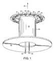
- FIG. 1shows schematic view of a plate supporting a plurality of LED light sources coupled to stem with a heat sink.
- FIG. 2shows an alternative plate and stem supporting a plurality of LED light sources.
- FIG. 3shows an alternative plate and stem supporting a plurality of LED light sources.
- FIG. 4shows a plate supporting a plurality of LED light sources
- FIG. 5shows an alternative plate supporting a plurality of LED chips sources coupled to a support stem.
- FIG. 6shows a plate for supporting a plurality of LED light sources
- FIG. 7shows a stem for supporting a plate.
- FIG. 8shows a bottom perspective view of the construction of FIG. 3
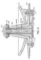
- FIG. 9shows a cross sectional of an alternative LED lamp assembly of FIG. 8
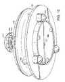
- FIG. 10shows a bottom perspective view of the alternative LED lamp assembly of FIG. 9
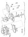
- FIG. 11shows an exploded view of the LED lamp assembly of FIGS. 8 , 9 and 10
- FIG. 12shows a perspective view of the assembled lamp of FIG. 11 .
- a light source assemblymay be formed from a heat conductive plate, supporting a plurality of LEDs; and connecting electrical circuitry.
- a heat conductive stem to duct heat from the platesupports the plate. The stem may be further supported on a base.
- FIG. 1shows a schematic design of a simple plate 20 supporting a plurality of LED light sources 30 connected by circuit traces (electrical circuitry 40 ).
- the LEDs 30are mounted on circuitry pads 44 .
- the preferred plate 20may be formed from a metal or circuit board material with an inner side 22 and an outer side 24 facing in a forward direction 26 .
- the plate 20is a substantially solid, heat conductive piece. It is preferably round to enable rotational processing during LED mounting and assembly. It is a convenient aspect of the circular plate structure, that the plate 20 may be axially mounted in a machine for indexed rotation to LED mounting stations.
- the plate 20may then be populated with LEDs 30 by indexed rotations followed by robotic welding of an LED chip to the pad 44 , followed by jump wire or similar welds between the pads 44 , and the LED chips.
- the plate, LEDs and circuitrymay be similarly rotated through a coating material to preserve and protect the LEDs. It is understood that other plate shapes may be used. Coupling features may be included in the plate such as a soldier or glue groove, a threaded hole, or a through passage for a threaded coupling, and so on enabling the plate 20 to be joined to the supporting stem 50 .
- the plate 20may include electrical wire ways, or other electrical connection accommodating features to enable the LEDs and circuitry to be coupled on one or both sides in a convenient fashion.
- the plate 20may also include decorative or esthetic features, such as a dome or similar shape with a mirror, white, black or colored front surface.
- the preferred plate 20carries printed circuit traces 40 .
- the circuit traceslink the LEDs 30 in a series circuit.
- the circuit traces 40may be formed in substantially known ways by laying down insulating, conductive, and protective layers as may be necessary in electrically conductive strips 42 connecting a plurality of mounting pads 44 .
- the mounting pads 44may be structured to support either LED chips (“chip on board” structure) or LED packages (such as TOPLEDs).
- the electrical circuitry 40is formed on one side of the plate, and more particularly the inside surface 22 .
- the trace lines 42then link to the series of pads 44 arranged in one or more rings around the center of the plate 20 . It is understood that there may be more then one series of LEDs within the various circuitry alternatives.
- first ring and a second ringthere may be a first ring and a second ring, or alternate LEDs may be coupled in a first group and a second group thereby enabling a low beam (one set of LEDs illuminated) and a high beam (an alternative set or both sets of LEDs illuminated), or enables a white output and a separate colored (red, amber, etc.) output.
- tune the light beam in the circuitrylay out by segmenting the rings into subsets enabling in right or left side illuminations that in combination with a reflector provide for beams angled to the right or left that may be combined in adjustable ratios. Similarly one may tune the intensity of such beam angling.
- LEDs 30are mounted on the pads 44 and finally coupled into the circuit structure 40 .
- LEDLED
- the typical commodity LED packagecomprising an LED chip, a reflector, and wire connections that are then enclosed in a plastic housing.
- These pre-assembled LED package unitscan be less thermally and optically efficient than individually mounted LED chips (“chip on board”).
- a preferred aspect of the present designis to use a “chip on board” construction, where the LED chips are mounted directly on the support structure, enabling relatively greater heat removal, and greater light emission.
- the preferred general methodis to couple the LED chip to a first conductive surface of a pad 44 , and then connect a jumper wired from an exposed side of the LED chip to a second coupling point on that pad 44 .
- the pads (and LEDs)are then chained together in a series circuit 40 .
- the series circuit 40is a preferred because failure of one LED causes the lamp to go out, forcing replacement of the whole failing structure.
- a parallel circuittolerates a progressive failure of individual LEDs that can be a deceptively dangerous reduction in total light as successive LEDs fail.
- the plate 20is mounted on a thermally conductive stem 50 to conduct heat away form the plate.
- the stem 50may be a hollow column with an exterior surface 52 formed to be reflective to enhance light output, or formed to be minimally reflective to enhance the system optics and limit uncontrolled light projection (glare) as may be preferred.
- the stem 50is preferably in turn coupled to a thermally conductive radiator, such as a heat conductive disk 60 . Electrical connectors 38 may be passed through the column 50 and disk 60 to be connected to the circuit 40 on plate 20
- FIG. 2shows an alternative schematic view of a flat plate 220 supporting LED chips 230 on pads 244 electrically coupled by circuit traces 240 .
- the plate 220is mechanically coupled to a stem 250 with a curved reflective surface 252 designed to direct light from the LEDs 230 sideways to other optical elements, such as a reflector, lens or light guide.
- the stem 250includes a central passage for electrical leads 238 to couple with the circuit traces 240 .
- the plate 220was about 13 millimeters in diameter, and about 1.6 millimeters thick. Eight LEDs were equally distributed around the periphery of the lower side of the plate.
- the stem 50 , 250may be a simple hollow tube formed by known techniques to support the plate 20 , 220 .
- the preferred stem 50 , 250is structured to conduct heat from the plate 20 , 220 .
- a metal stem 50 , 250is preferred.
- the plate 20 , 220may be welded, screwed, soldiered, glued, or similarly coupled to the forward or distal end of the stem 50 , 250 .
- the opposite end or base of the stem 50 , 250may be conveniently formed to couple to a base structure. In a vehicle context, a lamp is subject to constant vibration.
- the stem 50should then be sufficiently stiff to prevent sway of the plate 20 during normal operation.
- the preferred stemhas an outer diameter about half the diameter of the plate.
- the stem 50 , 250has a hollow center.
- the electrical connection leads 38 , 238may then be extended through the hollow center of the stem 50 , 250 .
- the exterior surface of the stem 50 , 250is exposed to the light generated by the LEDs 30 , 230 .
- the exterior surface 52 , 252 of the stemshould then be appropriately designed optically.
- the exterior surface 52 , 252 of the stemincludes a mirror finish and is smoothly arced to direct light towards an associated optical system of a reflector and lens.
- Optical designis considered to be in the scope of skilled art given the preferred beam pattern, and similar design choices and requirements.
- the stemis a straight, narrow column to minimize interception and reflection of light from the LEDs.
- the preferred stemis mechanically coupled to a base, which may include coupling features to join with a reflector or similar optical housing by known methods.
- the base structurealso includes heat-sinking features.
- the stemthen provides a heat conductive path from the plate to the heat sinking features.
- the plate 20 and the stem 50should then have a sufficiently broad coupling to enable good heat flow from one to the other.
- the stem 50should have an equally or even broader base to conduct heat from the stem.
- the lamp assemblymay be structured to be replaceable with respect to a reflector or similar optical assembly. This generally requires a more expensive socket to enable correct positioning of the LED lamp assembly, exclusion of water and dirt, and so on while tolerating the removal and replacement of the standard lamp. Because LEDs can have a life of up to 100,000 hours, there may be no reason to enable lamp replacement.
- the LED lamp assemblymay then be designed as a standard component that is permanently installed in a selected one of many possible optical housings (reflector or lens system) with the expectation that if there were a failure, the whole lamp structure would be replaced. The cost of the socket is then reduced. The whole lamp assembly may be factory aimed, and sealed.
- the standard LED lamp assemblycan then be used as a standard component with any number differing optical housing systems.
- FIG. 3shows an alternative plate and stem supporting a plurality of LED light sources.
- the plate 320includes a series of peripheral petal like tabs 340 that are bent upwards at an angle to the plane transverse to the stem axis. Each tab 340 supports an LED assembly (package, or chip on board). Plate 320 is trapped between the stem 350 and a heat conductive head 360 .
- the coupling between the stem 350 and the head 360may be a compression fit, bayonet mount or a similar construction.
- the stem 350 endincludes two semicircular pillars 370 that form a tight compression fit with one or more recesses formed in the head 360 .
- the plate 320is trapped in the compression between the stem 350 and the dome 360 enabling good thermal conduction from the plate 320 and to the head 360 and stem 350 .
- the plate 320may be held in a recess formed on the top of the stem 350 .
- Connecting electrical leads 338may be extended through the stem 350 to the base assembly for electrical connection.
- the plate 320may be held in place by compression, friction, potting, epoxy, or other methods.
- the platehad a thickness of about 1 millimeter.
- the platehad ten peripheral tabs that were conveniently bent at a 52 degree angle to the plane transverse to the stem axis.
- the domehad a diameter of about 20 millimeters.
- the dome to base distancewas about 24 millimeters.
- the stem 350was made of copper and had a middle height diameter of about 8 millimeters.
- the mating surface 384had a diameter of about 21 millimeters.
- FIG. 4shows a convenient layout of a stamped disk 400 with a crossbar 430 and two cut outs 440 that can mate with the two semicircular pillars 370 .
- the crossbar 430is formed to align the disk 400 rotationally with the respect to the stem 350 .
- the radial edge of the disk 400is formed with a plurality of radially extending tabs or fingers 410 that support LED packages 420 .
- the fingers 410are angled with respect to the stem axis to point the LEDs 420 in a preferred direction, and correspondingly touch the lower (inside) surface of the head 360 for thermal conduction from the disk 400 .
- FIG. 5shows a similar disk 500 with fingers 510 supporting a chip on board construction with LED 520 . Again the circuit traces are not shown.
- FIG. 6shows a similar stamped disk 600 .
- the disk 600may be made from a material with high thermal conductivity, such as copper.
- the disk 600may be stamped to have facets 610 to support circuitry and align corresponding LED packages or LED chips (“chip on board”) as the case may be in a preferred angle to the lamp (stem) axis, while the center region 620 of the disk 600 is in thermally conductive contact with an associated stem and head if any.
- the preferred stem 350is supported in a thermally conductive disk or plate 380 that is exposed at least along its circumference edge 382 to air.
- the preferred plate 380is cast or stamped metal, such as cast zinc or stamped copper, and may be blackened to enhance thermal radiation.
- the front side of the plate 380may include appropriate mating features 384 to guide or couple the lamp assembly into a lamp socket.
- the mating features 384may be a threading, bayonet, clip latching, compression fit or other known latching features.
- the plate 380had a mating diameter (at 384 ) of 21 millimeters, and a peripheral diameter (at 382 ) of about 36 millimeters.
- the preferred plate 380includes a back 386 abutting an electrically insulating portion 390 enclosing circuitry for the lamp supported on a circuit board 392 .
- a cover 394may be attached to enclose the circuit board 392 , allowing electrical connectors to protrude such as lug ends 396 .
- FIG. 8shows a bottom perspective view of the construction of FIG. 3
- the angle of the fingers, or of the bevel with respect to the stemcan then be set in advance to influence the degree of light spread, or other optical purposes.
- Interchangeable partsmay then include stems of differing lengths, plates of differing radii, or circuitry, and fingers with differing angularity, and LEDs of differing colors, all of which may otherwise have standard assembly features. In this way a variety of lamp performances may be achieved from mixing and matching a limited number of basic parts that may otherwise be assembled in standard ways.
- the forward (or top) surface of the platemay be enclosed with an esthetic, light or heat reflective shield, or heat dissipating plate or head 360 .
- a shield, cover or head 360may be attached to the plate by numerous known methods, including press fitting one or more extensions into one or more recesses.
- FIG. 9shows a mushroom type lamp coupled to a heat sink-radiator.
- the head 910 and stem 920 of the mushroomare made of metal to conduct heat to the radiator 924 .
- the LEDs 930are mounted on a disk 940 under the rim of the cap 910 to direct light generally down toward the stem 920 and the surrounding reflector 922 .
- the LEDs 930are mounted to the disk 920 so as to conduct heat to the cap 910 , and stem 920 for conduction to the radiator 924 .
- the bottom side of the radiator 924is preferably formed with a cavity to retain a circuit board 950 for controlling the LEDs 930 .
- the circuit board 950may be pressed in place or similarly mounted as may be convenient.
- a cover plate for the cavitymay be used to shield the circuit board.
- the dome 910had a diameter of about 20 millimeters, and the stem had a wall thickness of about 3 millimeters.
- the preferred alternative stem 920is formed with a heat radiating skirt 924 as a single piece.
- the skirt 924may include through passages so as to be screwed or riveted to the back of the reflector 922 . Latching, snap, clip or similar coupling features may be formed on the skirt and reflector (or optical housing) to couple the two pieces.
- Conductive leads 960 , 962extend from the disk 940 through the stem 920 to the circuit board 950 . Guiding and insulating the leads 960 , 962 is or are one or more electrically insulating lead guides 964 , 966 designed to funnel the leads through the stem passage (or passages) for exposure and connection of the distal (front end) of the stem 920 .
- the stem centeris funnel shaped and the lead guides 964 , 966 are conformally shaped conical sections.
- the lead endsproject at each end of the insulating sheath so the contact may be made at the LED end and the circuit board end. It is convenient to form the core passage as a funnel or funnels and the insulative sheath or sheath sections as cone that mate with the funnels. In this way the leads may be easily positioned correctly in the core of the stem.
- FIG. 10shows a bottom perspective view of the LED lamp assembly of FIG. 9 having the heat radiating skirt 924 screwed by screws 970 to the back of the reflector 922 .
- FIG. 11shows the LED lamp assembly inserted axially through a rear hole formed in a reflector or housing with the cap 910 and stem 920 substantially extending above the surface of the reflector 922 .
- the heat sink 924may be mounted to stand off bosses 928 molded into the back of the reflector or housing using rivets or screws for example.
- FIG. 12shows a schematic view of the assembly sequence of the second embodiment.
- the plate 920 with the attached LEDs 930is formed in advance.
- the circuit board 950 and cover plate if anyare formed in advance.
- the leads 960 , 962are attached to the circuit board 950 .
- the insulating guides 964 , 966are threaded over the leads 960 , 962 .
- the circuit board assemblyis pressed, riveted or screwed into the cavity formed in the back of the stem, so the leads end are exposed to the stem front.
- the preformed disk 940 carrying the LEDs 930is then positioned on the stem end and the electrical connections to the leads 960 , 962 completed.
- the rivet end 912 of the dome 910is then pressed through a hole in the disk 940 to mate with the distal end of the stem 920 , pinching the plate 940 in place and completing thermal conduction path from the plate 940 .
- the lamp assemblyis now complete.
- the dome end of the lampmay be threaded through a reflector opening. Keyways, seals, and similar features typical of lamp to reflector couplings may be used as are known in the art.
- the lampis now properly positioned with respect to the reflector.
- the skirt 924 as shownmay be screwed to the back of the reflector 922 .
- the disk supporting the LEDsprovides a convenient preassembly platform enabling convenient manufacture.
- the close mounting of the LEDsprovides relatively good intensity as a light source.
- the solid thermal coupling of the disk to the dome, stem and heat sink radiating skirtprovides good thermal dissipation of heat generated by the concentrated array of LEDs.
Landscapes
- Engineering & Computer Science (AREA)
- General Engineering & Computer Science (AREA)
- Physics & Mathematics (AREA)
- Microelectronics & Electronic Packaging (AREA)
- Optics & Photonics (AREA)
- Arrangement Of Elements, Cooling, Sealing, Or The Like Of Lighting Devices (AREA)
- Fastening Of Light Sources Or Lamp Holders (AREA)
- Non-Portable Lighting Devices Or Systems Thereof (AREA)
Abstract
Description
Claims (4)
Priority Applications (5)
| Application Number | Priority Date | Filing Date | Title |
|---|---|---|---|
| US10/802,517US7093958B2 (en) | 2002-04-09 | 2004-03-17 | LED light source assembly |
| CA002472662ACA2472662A1 (en) | 2003-07-28 | 2004-06-28 | Led light source assembly |
| EP04017718AEP1503139A3 (en) | 2003-07-28 | 2004-07-27 | LED light source assembly |
| JP2004218739AJP2005050811A (en) | 2003-07-28 | 2004-07-27 | LED light source assembly |
| US11/347,597US7360925B2 (en) | 2003-07-28 | 2006-02-03 | LED light source assembly |
Applications Claiming Priority (3)
| Application Number | Priority Date | Filing Date | Title |
|---|---|---|---|
| US37101502P | 2002-04-09 | 2002-04-09 | |
| US49049303P | 2003-07-28 | 2003-07-28 | |
| US10/802,517US7093958B2 (en) | 2002-04-09 | 2004-03-17 | LED light source assembly |
Related Child Applications (1)
| Application Number | Title | Priority Date | Filing Date |
|---|---|---|---|
| US11/347,597ContinuationUS7360925B2 (en) | 2003-07-28 | 2006-02-03 | LED light source assembly |
Publications (2)
| Publication Number | Publication Date |
|---|---|
| US20050024870A1 US20050024870A1 (en) | 2005-02-03 |
| US7093958B2true US7093958B2 (en) | 2006-08-22 |
Family
ID=33544746
Family Applications (2)
| Application Number | Title | Priority Date | Filing Date |
|---|---|---|---|
| US10/802,517Expired - LifetimeUS7093958B2 (en) | 2002-04-09 | 2004-03-17 | LED light source assembly |
| US11/347,597Expired - Fee RelatedUS7360925B2 (en) | 2003-07-28 | 2006-02-03 | LED light source assembly |
Family Applications After (1)
| Application Number | Title | Priority Date | Filing Date |
|---|---|---|---|
| US11/347,597Expired - Fee RelatedUS7360925B2 (en) | 2003-07-28 | 2006-02-03 | LED light source assembly |
Country Status (4)
| Country | Link |
|---|---|
| US (2) | US7093958B2 (en) |
| EP (1) | EP1503139A3 (en) |
| JP (1) | JP2005050811A (en) |
| CA (1) | CA2472662A1 (en) |
Cited By (95)
| Publication number | Priority date | Publication date | Assignee | Title |
|---|---|---|---|---|
| US20060138435A1 (en)* | 2003-05-01 | 2006-06-29 | Cree, Inc. | Multiple component solid state white light |
| US20060152140A1 (en)* | 2005-01-10 | 2006-07-13 | Brandes George R | Light emission device |
| US20070115228A1 (en)* | 2005-11-18 | 2007-05-24 | Roberts John K | Systems and methods for calibrating solid state lighting panels |
| US7246919B2 (en) | 2004-03-03 | 2007-07-24 | S.C. Johnson & Son, Inc. | LED light bulb with active ingredient emission |
| US20070247414A1 (en)* | 2006-04-21 | 2007-10-25 | Cree, Inc. | Solid state luminaires for general illumination |
| US20070263393A1 (en)* | 2006-05-05 | 2007-11-15 | Led Lighting Fixtures, Inc. | Lighting device |
| US20070262337A1 (en)* | 2006-04-21 | 2007-11-15 | Cree, Inc. | Multiple thermal path packaging for solid state light emitting apparatus and associated assembling methods |
| US20070278974A1 (en)* | 2006-05-31 | 2007-12-06 | Led Lighting Fixtures, Inc. | Lighting device with color control, and method of lighting |
| US7318659B2 (en) | 2004-03-03 | 2008-01-15 | S. C. Johnson & Son, Inc. | Combination white light and colored LED light device with active ingredient emission |
| US20080062691A1 (en)* | 2006-09-12 | 2008-03-13 | Russell George Villard | LED lighting fixture |
| US20080062689A1 (en)* | 2006-09-12 | 2008-03-13 | Russell George Villard | Led lighting fixture |
| US20080117647A1 (en)* | 2004-12-22 | 2008-05-22 | Patent-Treuhand-Gesellschaft Fur Elektrische Gluhlampen Mbh | Lighting Device Comprising at Least One Light-Emitting Diode and Vehicle Headlight |
| US20080192493A1 (en)* | 2007-02-12 | 2008-08-14 | Cree, Inc. | High thermal conductivity packaging for solid state light emitting apparatus and associated assembling methods |
| US20080231201A1 (en)* | 2007-03-22 | 2008-09-25 | Robert Higley | Led lighting fixture |
| US20080259589A1 (en)* | 2007-02-22 | 2008-10-23 | Led Lighting Fixtures, Inc. | Lighting devices, methods of lighting, light filters and methods of filtering light |
| US20080278955A1 (en)* | 2007-05-07 | 2008-11-13 | Boyer John Delmore | Led lamp device and method to retrofit a lighting fixture |
| US20090002986A1 (en)* | 2007-06-27 | 2009-01-01 | Cree, Inc. | Light Emitting Device (LED) Lighting Systems for Emitting Light in Multiple Directions and Related Methods |
| US20090002979A1 (en)* | 2007-06-27 | 2009-01-01 | Cree, Inc. | Light emitting device (led) lighting systems for emitting light in multiple directions and related methods |
| US7476002B2 (en) | 2003-07-02 | 2009-01-13 | S.C. Johnson & Son, Inc. | Color changing light devices with active ingredient and sound emission for mood enhancement |
| US7484860B2 (en) | 2003-07-02 | 2009-02-03 | S.C. Johnson & Son, Inc. | Combination white light and colored LED light device with active ingredient emission |
| USD586751S1 (en) | 2004-04-22 | 2009-02-17 | Osram Sylvania, Inc. | Light emitting diode bulb connector |
| US7503675B2 (en) | 2004-03-03 | 2009-03-17 | S.C. Johnson & Son, Inc. | Combination light device with insect control ingredient emission |
| US7520635B2 (en) | 2003-07-02 | 2009-04-21 | S.C. Johnson & Son, Inc. | Structures for color changing light devices |
| US20090103294A1 (en)* | 2007-10-19 | 2009-04-23 | Fu Zhun Precision Industry (Shen Zhen) Co., Ltd. | Led lamp with a heat sink |
| US20090168354A1 (en)* | 2007-12-26 | 2009-07-02 | Radesh Jewram | Thermally and electrically conductive interconnect structures |
| US20090225540A1 (en)* | 2005-06-03 | 2009-09-10 | Jen-Shyan Chen | Semiconductor Light-Emitting Apparatus Integrated with Heat-Conducting/ Dissipating Module |
| US20090244900A1 (en)* | 2008-03-28 | 2009-10-01 | Delta Electronics Inc. | Illuminating device and heat-dissipating structure thereof |
| US7604378B2 (en) | 2003-07-02 | 2009-10-20 | S.C. Johnson & Son, Inc. | Color changing outdoor lights with active ingredient and sound emission |
| US20090296411A1 (en)* | 2008-05-28 | 2009-12-03 | Delta Electronics Inc. | Illuminating device and heat-dissipating structure thereof |
| US7648257B2 (en) | 2006-04-21 | 2010-01-19 | Cree, Inc. | Light emitting diode packages |
| USD610543S1 (en) | 2004-04-22 | 2010-02-23 | Osram Sylvania, Inc. | Light emitting diode bulb connector |
| US20100053963A1 (en)* | 2008-08-27 | 2010-03-04 | Fu Zhun Precision Industry (Shen Zhen) Co., Ltd. | Led lamp |
| US20100073930A1 (en)* | 2008-09-23 | 2010-03-25 | Lsi Industries, Inc. | Lighting Apparatus with Heat Dissipation System |
| US7744243B2 (en) | 2007-05-08 | 2010-06-29 | Cree Led Lighting Solutions, Inc. | Lighting device and lighting method |
| USD619964S1 (en) | 2004-04-22 | 2010-07-20 | Osram Sylvania, Inc. | Light emitting diode bulb connector |
| US7768192B2 (en) | 2005-12-21 | 2010-08-03 | Cree Led Lighting Solutions, Inc. | Lighting device and lighting method |
| US20100277916A1 (en)* | 2009-04-29 | 2010-11-04 | Hiroshi Kira | LED Light Module and Modular Lighting System |
| US7828460B2 (en) | 2006-04-18 | 2010-11-09 | Cree, Inc. | Lighting device and lighting method |
| US20100328938A1 (en)* | 2009-06-24 | 2010-12-30 | Fu Zhun Precision Industry (Shen Zhen) Co., Ltd. | Led lighting module with large light emitting angle |
| US7863635B2 (en) | 2007-08-07 | 2011-01-04 | Cree, Inc. | Semiconductor light emitting devices with applied wavelength conversion materials |
| USD631183S1 (en) | 2008-09-23 | 2011-01-18 | Lsi Industries, Inc. | Lighting fixture |
| US7901107B2 (en) | 2007-05-08 | 2011-03-08 | Cree, Inc. | Lighting device and lighting method |
| US7918581B2 (en) | 2006-12-07 | 2011-04-05 | Cree, Inc. | Lighting device and lighting method |
| US7926300B2 (en) | 2005-11-18 | 2011-04-19 | Cree, Inc. | Adaptive adjustment of light output of solid state lighting panels |
| US20110148270A1 (en)* | 2009-12-21 | 2011-06-23 | Malek Bhairi | Spherical light output LED lens and heat sink stem system |
| US7997745B2 (en) | 2006-04-20 | 2011-08-16 | Cree, Inc. | Lighting device and lighting method |
| US8008676B2 (en) | 2006-05-26 | 2011-08-30 | Cree, Inc. | Solid state light emitting device and method of making same |
| US8018135B2 (en) | 2007-10-10 | 2011-09-13 | Cree, Inc. | Lighting device and method of making |
| US8029155B2 (en) | 2006-11-07 | 2011-10-04 | Cree, Inc. | Lighting device and lighting method |
| US8038317B2 (en) | 2007-05-08 | 2011-10-18 | Cree, Inc. | Lighting device and lighting method |
| US8079729B2 (en) | 2007-05-08 | 2011-12-20 | Cree, Inc. | Lighting device and lighting method |
| US8125137B2 (en) | 2005-01-10 | 2012-02-28 | Cree, Inc. | Multi-chip light emitting device lamps for providing high-CRI warm white light and light fixtures including the same |
| US8123384B2 (en) | 2007-07-17 | 2012-02-28 | Cree, Inc. | Optical elements with internal optical features and methods of fabricating same |
| US8222584B2 (en) | 2003-06-23 | 2012-07-17 | Abl Ip Holding Llc | Intelligent solid state lighting |
| US8240875B2 (en) | 2008-06-25 | 2012-08-14 | Cree, Inc. | Solid state linear array modules for general illumination |
| US8328376B2 (en) | 2005-12-22 | 2012-12-11 | Cree, Inc. | Lighting device |
| US8337071B2 (en) | 2005-12-21 | 2012-12-25 | Cree, Inc. | Lighting device |
| US20130039063A1 (en)* | 2008-12-12 | 2013-02-14 | The Sloan Company, Inc. Dba Sloanled | Angled emitter channel letter lighting |
| US8513875B2 (en) | 2006-04-18 | 2013-08-20 | Cree, Inc. | Lighting device and lighting method |
| US8514210B2 (en) | 2005-11-18 | 2013-08-20 | Cree, Inc. | Systems and methods for calibrating solid state lighting panels using combined light output measurements |
| WO2013152286A1 (en)* | 2012-04-06 | 2013-10-10 | Cree, Inc. | Led light fixture with facilitated lensing alignment and method of manufacture |
| US8596819B2 (en) | 2006-05-31 | 2013-12-03 | Cree, Inc. | Lighting device and method of lighting |
| US8759733B2 (en) | 2003-06-23 | 2014-06-24 | Abl Ip Holding Llc | Optical integrating cavity lighting system using multiple LED light sources with a control circuit |
| US8866410B2 (en) | 2007-11-28 | 2014-10-21 | Cree, Inc. | Solid state lighting devices and methods of manufacturing the same |
| US8876322B2 (en) | 2012-06-20 | 2014-11-04 | Journée Lighting, Inc. | Linear LED module and socket for same |
| US8921876B2 (en) | 2009-06-02 | 2014-12-30 | Cree, Inc. | Lighting devices with discrete lumiphor-bearing regions within or on a surface of remote elements |
| US8967821B2 (en) | 2009-09-25 | 2015-03-03 | Cree, Inc. | Lighting device with low glare and high light level uniformity |
| US9028097B2 (en) | 2009-10-30 | 2015-05-12 | Cree, Inc. | LED apparatus and method for accurate lens alignment |
| US9084328B2 (en) | 2006-12-01 | 2015-07-14 | Cree, Inc. | Lighting device and lighting method |
| TWI499736B (en)* | 2010-03-29 | 2015-09-11 | Heraeus Nobleight Gmbh | Led lamp for homogeneous illumination of hollow bodies |
| US9275979B2 (en) | 2010-03-03 | 2016-03-01 | Cree, Inc. | Enhanced color rendering index emitter through phosphor separation |
| US9404634B2 (en) | 2009-10-30 | 2016-08-02 | Cree, Inc. | LED light fixture with facilitated lensing alignment and method of manufacture |
| US9441793B2 (en) | 2006-12-01 | 2016-09-13 | Cree, Inc. | High efficiency lighting device including one or more solid state light emitters, and method of lighting |
| US9565782B2 (en) | 2013-02-15 | 2017-02-07 | Ecosense Lighting Inc. | Field replaceable power supply cartridge |
| US9568665B2 (en) | 2015-03-03 | 2017-02-14 | Ecosense Lighting Inc. | Lighting systems including lens modules for selectable light distribution |
| USD782093S1 (en) | 2015-07-20 | 2017-03-21 | Ecosense Lighting Inc. | LED luminaire having a mounting system |
| USD782094S1 (en) | 2015-07-20 | 2017-03-21 | Ecosense Lighting Inc. | LED luminaire having a mounting system |
| USD785218S1 (en) | 2015-07-06 | 2017-04-25 | Ecosense Lighting Inc. | LED luminaire having a mounting system |
| US9651232B1 (en) | 2015-08-03 | 2017-05-16 | Ecosense Lighting Inc. | Lighting system having a mounting device |
| US9651227B2 (en) | 2015-03-03 | 2017-05-16 | Ecosense Lighting Inc. | Low-profile lighting system having pivotable lighting enclosure |
| US9651216B2 (en) | 2015-03-03 | 2017-05-16 | Ecosense Lighting Inc. | Lighting systems including asymmetric lens modules for selectable light distribution |
| US9746159B1 (en) | 2015-03-03 | 2017-08-29 | Ecosense Lighting Inc. | Lighting system having a sealing system |
| US9869450B2 (en) | 2015-02-09 | 2018-01-16 | Ecosense Lighting Inc. | Lighting systems having a truncated parabolic- or hyperbolic-conical light reflector, or a total internal reflection lens; and having another light reflector |
| US10030824B2 (en) | 2007-05-08 | 2018-07-24 | Cree, Inc. | Lighting device and lighting method |
| US10477636B1 (en) | 2014-10-28 | 2019-11-12 | Ecosense Lighting Inc. | Lighting systems having multiple light sources |
| US10615324B2 (en) | 2013-06-14 | 2020-04-07 | Cree Huizhou Solid State Lighting Company Limited | Tiny 6 pin side view surface mount LED |
| US10989372B2 (en) | 2017-03-09 | 2021-04-27 | Ecosense Lighting Inc. | Fixtures and lighting accessories for lighting devices |
| US11022279B2 (en) | 2016-03-08 | 2021-06-01 | Ecosense Lighting Inc. | Lighting system with lens assembly |
| US11028980B2 (en) | 2013-10-30 | 2021-06-08 | Ecosense Lighting Inc. | Flexible strip lighting apparatus and methods |
| US11041609B2 (en) | 2018-05-01 | 2021-06-22 | Ecosense Lighting Inc. | Lighting systems and devices with central silicone module |
| US11251164B2 (en) | 2011-02-16 | 2022-02-15 | Creeled, Inc. | Multi-layer conversion material for down conversion in solid state lighting |
| US11296057B2 (en) | 2017-01-27 | 2022-04-05 | EcoSense Lighting, Inc. | Lighting systems with high color rendering index and uniform planar illumination |
| US11306897B2 (en) | 2015-02-09 | 2022-04-19 | Ecosense Lighting Inc. | Lighting systems generating partially-collimated light emissions |
| US11353200B2 (en) | 2018-12-17 | 2022-06-07 | Korrus, Inc. | Strip lighting system for direct input of high voltage driving power |
| US12388056B1 (en) | 2017-01-27 | 2025-08-12 | Korrus, Inc. | Linear lighting systems and processes |
Families Citing this family (59)
| Publication number | Priority date | Publication date | Assignee | Title |
|---|---|---|---|---|
| US7059748B2 (en)* | 2004-05-03 | 2006-06-13 | Osram Sylvania Inc. | LED bulb |
| US20060082315A1 (en)* | 2004-10-20 | 2006-04-20 | Timothy Chan | Method and system for attachment of light emmiting diodes to circuitry for use in lighting |
| US7275839B2 (en)* | 2005-04-05 | 2007-10-02 | Osram Sylvania, Inc. | Three color LED bulb |
| JP2006313808A (en)* | 2005-05-09 | 2006-11-16 | Okaya Electric Ind Co Ltd | Light emitting diode lamp |
| US7201489B2 (en)* | 2005-06-15 | 2007-04-10 | Shing-Jy Shyu | Ceiling fan light LED assembly device |
| WO2007034361A1 (en)* | 2005-09-22 | 2007-03-29 | Philips Intellectual Property & Standards Gmbh | Led lighting module |
| TWI391600B (en)* | 2005-09-27 | 2013-04-01 | Koninkl Philips Electronics Nv | Led lighting fixtures |
| SG139583A1 (en)* | 2006-07-24 | 2008-02-29 | L & K Engineering Co Ltd | Lamp assembly |
| US7841741B2 (en)* | 2007-04-02 | 2010-11-30 | Endicott Interconnect Technologies, Inc. | LED lighting assembly and lamp utilizing same |
| CN201078679Y (en)* | 2007-07-02 | 2008-06-25 | 深圳市泓亚光电子有限公司 | LED straight inserting type multi-core high power light source |
| US7828461B2 (en)* | 2007-07-16 | 2010-11-09 | Lumination Llc | LED luminaire for generating substantially uniform illumination on a target plane |
| US7665866B2 (en)* | 2007-07-16 | 2010-02-23 | Lumination Llc | LED luminaire for generating substantially uniform illumination on a target plane |
| US10655837B1 (en) | 2007-11-13 | 2020-05-19 | Silescent Lighting Corporation | Light fixture assembly having a heat conductive cover with sufficiently large surface area for improved heat dissipation |
| US7810960B1 (en)* | 2007-11-13 | 2010-10-12 | Inteltech Corporation | Light fixture assembly having improved heat dissipation capabilities |
| US8534873B1 (en) | 2007-11-13 | 2013-09-17 | Inteltech Corporation | Light fixture assembly |
| US8789980B1 (en) | 2007-11-13 | 2014-07-29 | Silescent Lighting Corporation | Light fixture assembly |
| US9080760B1 (en) | 2007-11-13 | 2015-07-14 | Daryl Soderman | Light fixture assembly |
| US8360614B1 (en) | 2007-11-13 | 2013-01-29 | Inteltech Corporation | Light fixture assembly having improved heat dissipation capabilities |
| CN102943966B (en)* | 2007-12-13 | 2015-02-11 | 皇家飞利浦电子股份有限公司 | Light emitting diode disposed on heat dissipating device |
| US7625104B2 (en)* | 2007-12-13 | 2009-12-01 | Philips Lumileds Lighting Company, Llc | Light emitting diode for mounting to a heat sink |
| JP4450331B2 (en)* | 2008-02-29 | 2010-04-14 | 財団法人山形県産業技術振興機構 | Lighting device |
| US7841734B2 (en)* | 2008-05-27 | 2010-11-30 | Ruud Lighting, Inc. | LED lighting fixture |
| CN201293279Y (en)* | 2008-10-16 | 2009-08-19 | 郑榕彬 | LED lighting lamp |
| DE102009024907A1 (en) | 2009-06-15 | 2010-12-16 | Osram Gesellschaft mit beschränkter Haftung | Heat sink for semiconductor light elements |
| DE102009024904A1 (en) | 2009-06-15 | 2010-12-16 | Osram Gesellschaft mit beschränkter Haftung | Heat sink for semiconductor light elements |
| KR101114159B1 (en)* | 2009-07-23 | 2012-03-09 | 엘지이노텍 주식회사 | Lgiht emitting device |
| DE102009035515A1 (en)* | 2009-07-31 | 2011-02-03 | Osram Gesellschaft mit beschränkter Haftung | Lighting device and method for producing a lighting device |
| US9581756B2 (en) | 2009-10-05 | 2017-02-28 | Lighting Science Group Corporation | Light guide for low profile luminaire |
| US8672518B2 (en) | 2009-10-05 | 2014-03-18 | Lighting Science Group Corporation | Low profile light and accessory kit for the same |
| US9772099B2 (en) | 2009-10-05 | 2017-09-26 | Lighting Science Group Corporation | Low-profile lighting device and attachment members and kit comprising same |
| USD617493S1 (en) | 2009-10-06 | 2010-06-08 | Hubbell Incorporated | Flow-through LED carrier for luminaire |
| USD797980S1 (en) | 2010-05-06 | 2017-09-19 | Lighting Science Group Corporation | Low profile light |
| DE102010030296B4 (en)* | 2010-06-21 | 2012-11-22 | Osram Ag | Lamp with concave reflector and a projection for at least one light source |
| KR101123132B1 (en) | 2010-09-03 | 2012-03-20 | 테크원 주식회사 | LED type bulb having replaceable power supply |
| US8777455B2 (en)* | 2011-06-23 | 2014-07-15 | Cree, Inc. | Retroreflective, multi-element design for a solid state directional lamp |
| USD696436S1 (en) | 2011-06-23 | 2013-12-24 | Cree, Inc. | Solid state directional lamp |
| US8757840B2 (en) | 2011-06-23 | 2014-06-24 | Cree, Inc. | Solid state retroreflective directional lamp |
| US8616724B2 (en) | 2011-06-23 | 2013-12-31 | Cree, Inc. | Solid state directional lamp including retroreflective, multi-element directional lamp optic |
| US8777463B2 (en) | 2011-06-23 | 2014-07-15 | Cree, Inc. | Hybrid solid state emitter printed circuit board for use in a solid state directional lamp |
| US9055630B1 (en) | 2011-07-21 | 2015-06-09 | Dale B. Stepps | Power control system and method for providing an optimal power level to a designated light assembly |
| US8643300B1 (en) | 2011-07-21 | 2014-02-04 | Dale B. Stepps | Power control system and method for providing an optimal power level to a designated light fixture |
| MX339929B (en) | 2011-09-12 | 2016-06-17 | Rab Lighting Inc | Light fixture with airflow passage separating driver and emitter. |
| TW201337164A (en)* | 2012-03-12 | 2013-09-16 | Gem Weltronics Twn Corp | Method for manufacturing integrated multi-layer lighting device |
| JP2013196790A (en)* | 2012-03-15 | 2013-09-30 | Sharp Corp | Lighting device |
| US9313849B2 (en) | 2013-01-23 | 2016-04-12 | Silescent Lighting Corporation | Dimming control system for solid state illumination source |
| JP2014146510A (en)* | 2013-01-29 | 2014-08-14 | Panasonic Corp | Light source for lighting and lighting device |
| US9192001B2 (en) | 2013-03-15 | 2015-11-17 | Ambionce Systems Llc. | Reactive power balancing current limited power supply for driving floating DC loads |
| WO2015101420A1 (en)* | 2014-01-02 | 2015-07-09 | Tyco Electronics Nederland B.V. | Led socket assembly |
| US9410688B1 (en) | 2014-05-09 | 2016-08-09 | Mark Sutherland | Heat dissipating assembly |
| TWI595189B (en)* | 2014-09-02 | 2017-08-11 | Huan-Chiu Chou | Internal reflection lamp |
| FR3026467B1 (en)* | 2014-09-30 | 2019-10-04 | Valeo Vision | LUMINOUS MODULE COMPRISING AT LEAST ONE COMPONENT AND A CONNECTOR ARRANGED ON A HEAT SINK, AND LIGHTING DEVICE FOR A MOTOR VEHICLE COMPRISING SUCH A MODULE |
| US9380653B1 (en) | 2014-10-31 | 2016-06-28 | Dale Stepps | Driver assembly for solid state lighting |
| EP3244125A1 (en)* | 2016-05-13 | 2017-11-15 | Stephane Bochenek | Lighting device made up of luminous elements and striplight made up of a plurality of such lighting devices |
| US20180212116A1 (en)* | 2017-01-17 | 2018-07-26 | Astronics Dme Llc | Durable LED Light Engine for Airfield Guidance Sign |
| WO2018201643A1 (en)* | 2017-05-05 | 2018-11-08 | 广明源光科技股份有限公司 | Led lamp structure and preparation process therefor |
| CN107525027A (en)* | 2017-10-01 | 2017-12-29 | 张新春 | A kind of solar alarming lamp |
| US10773826B1 (en)* | 2019-10-15 | 2020-09-15 | Goodrich Lighting Systems, Inc. | Adjustable aiming aircraft light assembly |
| IT202000012004A1 (en)* | 2020-05-22 | 2021-11-22 | Mario Scalise | Diode lighting device |
| CN115413098B (en)* | 2022-10-28 | 2023-01-31 | 四川虹锐电工有限责任公司 | Lamp strip abnormity monitoring and controlling device, system and method |
Citations (3)
| Publication number | Priority date | Publication date | Assignee | Title |
|---|---|---|---|---|
| US20030016536A1 (en)* | 2001-07-23 | 2003-01-23 | Meng-Hsin Lin | Low-power high-intensity lighting apparatus |
| US20030063476A1 (en)* | 2001-09-28 | 2003-04-03 | English George J. | Replaceable LED lamp capsule |
| US20030227774A1 (en)* | 2002-06-10 | 2003-12-11 | Martin Paul S. | Axial LED source |
Family Cites Families (5)
| Publication number | Priority date | Publication date | Assignee | Title |
|---|---|---|---|---|
| WO2000017569A1 (en)* | 1998-09-17 | 2000-03-30 | Koninklijke Philips Electronics N.V. | Led lamp |
| US6773138B2 (en)* | 2002-04-09 | 2004-08-10 | Osram Sylvania Inc. | Snap together automotive led lamp assembly |
| US6715900B2 (en)* | 2002-05-17 | 2004-04-06 | A L Lightech, Inc. | Light source arrangement |
| JP2004206947A (en)* | 2002-12-24 | 2004-07-22 | Toyoda Gosei Co Ltd | Light emitting diode, lighting fixture and their process of manufacture |
| DE10302231A1 (en)* | 2003-01-20 | 2004-07-29 | Aqua Signal Aktiengesellschaft Spezialleuchtenfabrik | Lights, in particular air traffic control turn signals |
- 2004
- 2004-03-17USUS10/802,517patent/US7093958B2/ennot_activeExpired - Lifetime
- 2004-06-28CACA002472662Apatent/CA2472662A1/ennot_activeAbandoned
- 2004-07-27EPEP04017718Apatent/EP1503139A3/ennot_activeWithdrawn
- 2004-07-27JPJP2004218739Apatent/JP2005050811A/ennot_activeWithdrawn
- 2006
- 2006-02-03USUS11/347,597patent/US7360925B2/ennot_activeExpired - Fee Related
Patent Citations (3)
| Publication number | Priority date | Publication date | Assignee | Title |
|---|---|---|---|---|
| US20030016536A1 (en)* | 2001-07-23 | 2003-01-23 | Meng-Hsin Lin | Low-power high-intensity lighting apparatus |
| US20030063476A1 (en)* | 2001-09-28 | 2003-04-03 | English George J. | Replaceable LED lamp capsule |
| US20030227774A1 (en)* | 2002-06-10 | 2003-12-11 | Martin Paul S. | Axial LED source |
Cited By (168)
| Publication number | Priority date | Publication date | Assignee | Title |
|---|---|---|---|---|
| US8901585B2 (en) | 2003-05-01 | 2014-12-02 | Cree, Inc. | Multiple component solid state white light |
| US20060138435A1 (en)* | 2003-05-01 | 2006-06-29 | Cree, Inc. | Multiple component solid state white light |
| US7791092B2 (en) | 2003-05-01 | 2010-09-07 | Cree, Inc. | Multiple component solid state white light |
| US8222584B2 (en) | 2003-06-23 | 2012-07-17 | Abl Ip Holding Llc | Intelligent solid state lighting |
| US8759733B2 (en) | 2003-06-23 | 2014-06-24 | Abl Ip Holding Llc | Optical integrating cavity lighting system using multiple LED light sources with a control circuit |
| US8772691B2 (en) | 2003-06-23 | 2014-07-08 | Abl Ip Holding Llc | Optical integrating cavity lighting system using multiple LED light sources |
| US7618151B2 (en) | 2003-07-02 | 2009-11-17 | S.C. Johnson & Son, Inc. | Combination compact flourescent light with active ingredient emission |
| US7476002B2 (en) | 2003-07-02 | 2009-01-13 | S.C. Johnson & Son, Inc. | Color changing light devices with active ingredient and sound emission for mood enhancement |
| US7604378B2 (en) | 2003-07-02 | 2009-10-20 | S.C. Johnson & Son, Inc. | Color changing outdoor lights with active ingredient and sound emission |
| US7520635B2 (en) | 2003-07-02 | 2009-04-21 | S.C. Johnson & Son, Inc. | Structures for color changing light devices |
| US7484860B2 (en) | 2003-07-02 | 2009-02-03 | S.C. Johnson & Son, Inc. | Combination white light and colored LED light device with active ingredient emission |
| US7246919B2 (en) | 2004-03-03 | 2007-07-24 | S.C. Johnson & Son, Inc. | LED light bulb with active ingredient emission |
| US7318659B2 (en) | 2004-03-03 | 2008-01-15 | S. C. Johnson & Son, Inc. | Combination white light and colored LED light device with active ingredient emission |
| US7503675B2 (en) | 2004-03-03 | 2009-03-17 | S.C. Johnson & Son, Inc. | Combination light device with insect control ingredient emission |
| USD610991S1 (en) | 2004-04-22 | 2010-03-02 | Osram Sylvania, Inc. | Portion of a light emitting diode bulb connector |
| USD586751S1 (en) | 2004-04-22 | 2009-02-17 | Osram Sylvania, Inc. | Light emitting diode bulb connector |
| USD610545S1 (en) | 2004-04-22 | 2010-02-23 | Osram Sylvania, Inc. | Light emitting diode bulb connector |
| USD610544S1 (en) | 2004-04-22 | 2010-02-23 | Osram Sylvania, Inc. | Light emitting diode bulb connector |
| USD619964S1 (en) | 2004-04-22 | 2010-07-20 | Osram Sylvania, Inc. | Light emitting diode bulb connector |
| USD610543S1 (en) | 2004-04-22 | 2010-02-23 | Osram Sylvania, Inc. | Light emitting diode bulb connector |
| US7621667B2 (en)* | 2004-12-22 | 2009-11-24 | Osram Gesellschaft Mit Beschraenkter Haftung | Lighting device comprising at least one light-emitting diode and vehicle headlight |
| US20080117647A1 (en)* | 2004-12-22 | 2008-05-22 | Patent-Treuhand-Gesellschaft Fur Elektrische Gluhlampen Mbh | Lighting Device Comprising at Least One Light-Emitting Diode and Vehicle Headlight |
| US8847478B2 (en) | 2005-01-10 | 2014-09-30 | Cree, Inc. | Multi-chip light emitting device lamps for providing high-CRI warm white light and light fixtures including the same |
| US7564180B2 (en) | 2005-01-10 | 2009-07-21 | Cree, Inc. | Light emission device and method utilizing multiple emitters and multiple phosphors |
| US20090195137A1 (en)* | 2005-01-10 | 2009-08-06 | Cree, Inc. | Light emission device and method utilizing multiple emitters |
| US8410680B2 (en) | 2005-01-10 | 2013-04-02 | Cree, Inc. | Multi-chip light emitting device lamps for providing high-CRI warm white light and light fixtures including the same |
| US8120240B2 (en) | 2005-01-10 | 2012-02-21 | Cree, Inc. | Light emission device and method utilizing multiple emitters |
| US8125137B2 (en) | 2005-01-10 | 2012-02-28 | Cree, Inc. | Multi-chip light emitting device lamps for providing high-CRI warm white light and light fixtures including the same |
| US20060152140A1 (en)* | 2005-01-10 | 2006-07-13 | Brandes George R | Light emission device |
| US7963678B2 (en)* | 2005-06-03 | 2011-06-21 | Neobulb Technologies, Inc. | Semiconductor light-emitting apparatus integrated with heat-conducting/dissipating module |
| US20090225540A1 (en)* | 2005-06-03 | 2009-09-10 | Jen-Shyan Chen | Semiconductor Light-Emitting Apparatus Integrated with Heat-Conducting/ Dissipating Module |
| US8514210B2 (en) | 2005-11-18 | 2013-08-20 | Cree, Inc. | Systems and methods for calibrating solid state lighting panels using combined light output measurements |
| US7926300B2 (en) | 2005-11-18 | 2011-04-19 | Cree, Inc. | Adaptive adjustment of light output of solid state lighting panels |
| US20070115228A1 (en)* | 2005-11-18 | 2007-05-24 | Roberts John K | Systems and methods for calibrating solid state lighting panels |
| US8278846B2 (en) | 2005-11-18 | 2012-10-02 | Cree, Inc. | Systems and methods for calibrating solid state lighting panels |
| US7768192B2 (en) | 2005-12-21 | 2010-08-03 | Cree Led Lighting Solutions, Inc. | Lighting device and lighting method |
| US8878429B2 (en) | 2005-12-21 | 2014-11-04 | Cree, Inc. | Lighting device and lighting method |
| US8337071B2 (en) | 2005-12-21 | 2012-12-25 | Cree, Inc. | Lighting device |
| US8328376B2 (en) | 2005-12-22 | 2012-12-11 | Cree, Inc. | Lighting device |
| US8858004B2 (en) | 2005-12-22 | 2014-10-14 | Cree, Inc. | Lighting device |
| US8733968B2 (en) | 2006-04-18 | 2014-05-27 | Cree, Inc. | Lighting device and lighting method |
| US10018346B2 (en) | 2006-04-18 | 2018-07-10 | Cree, Inc. | Lighting device and lighting method |
| US9297503B2 (en) | 2006-04-18 | 2016-03-29 | Cree, Inc. | Lighting device and lighting method |
| US8513875B2 (en) | 2006-04-18 | 2013-08-20 | Cree, Inc. | Lighting device and lighting method |
| US7828460B2 (en) | 2006-04-18 | 2010-11-09 | Cree, Inc. | Lighting device and lighting method |
| US9417478B2 (en) | 2006-04-18 | 2016-08-16 | Cree, Inc. | Lighting device and lighting method |
| US8123376B2 (en) | 2006-04-18 | 2012-02-28 | Cree, Inc. | Lighting device and lighting method |
| US7997745B2 (en) | 2006-04-20 | 2011-08-16 | Cree, Inc. | Lighting device and lighting method |
| US9605835B2 (en) | 2006-04-21 | 2017-03-28 | Cree, Inc. | Solid-state luminaires for general illumination |
| US20070247414A1 (en)* | 2006-04-21 | 2007-10-25 | Cree, Inc. | Solid state luminaires for general illumination |
| US8294075B2 (en) | 2006-04-21 | 2012-10-23 | Cree, Inc. | Solid state luminaires for general illumination |
| US7777166B2 (en) | 2006-04-21 | 2010-08-17 | Cree, Inc. | Solid state luminaires for general illumination including closed loop feedback control |
| US7625103B2 (en) | 2006-04-21 | 2009-12-01 | Cree, Inc. | Multiple thermal path packaging for solid state light emitting apparatus and associated assembling methods |
| US8946609B2 (en) | 2006-04-21 | 2015-02-03 | Cree, Inc. | Solid state luminaires for general illumination |
| US7648257B2 (en) | 2006-04-21 | 2010-01-19 | Cree, Inc. | Light emitting diode packages |
| US20070262337A1 (en)* | 2006-04-21 | 2007-11-15 | Cree, Inc. | Multiple thermal path packaging for solid state light emitting apparatus and associated assembling methods |
| US7722220B2 (en)* | 2006-05-05 | 2010-05-25 | Cree Led Lighting Solutions, Inc. | Lighting device |
| WO2007130536A3 (en)* | 2006-05-05 | 2008-12-24 | Cree Led Lighting Solutions | Lighting device |
| US20070263393A1 (en)* | 2006-05-05 | 2007-11-15 | Led Lighting Fixtures, Inc. | Lighting device |
| US8008676B2 (en) | 2006-05-26 | 2011-08-30 | Cree, Inc. | Solid state light emitting device and method of making same |
| US8628214B2 (en) | 2006-05-31 | 2014-01-14 | Cree, Inc. | Lighting device and lighting method |
| US20070278974A1 (en)* | 2006-05-31 | 2007-12-06 | Led Lighting Fixtures, Inc. | Lighting device with color control, and method of lighting |
| US8596819B2 (en) | 2006-05-31 | 2013-12-03 | Cree, Inc. | Lighting device and method of lighting |
| US7969097B2 (en) | 2006-05-31 | 2011-06-28 | Cree, Inc. | Lighting device with color control, and method of lighting |
| US8408739B2 (en) | 2006-09-12 | 2013-04-02 | Cree, Inc. | LED lighting fixture |
| US20100214780A1 (en)* | 2006-09-12 | 2010-08-26 | Cree, Inc. | Led lighting fixture |
| US20080062691A1 (en)* | 2006-09-12 | 2008-03-13 | Russell George Villard | LED lighting fixture |
| US20080062689A1 (en)* | 2006-09-12 | 2008-03-13 | Russell George Villard | Led lighting fixture |
| US7766508B2 (en) | 2006-09-12 | 2010-08-03 | Cree, Inc. | LED lighting fixture |
| US7665862B2 (en) | 2006-09-12 | 2010-02-23 | Cree, Inc. | LED lighting fixture |
| US8646944B2 (en) | 2006-09-12 | 2014-02-11 | Cree, Inc. | LED lighting fixture |
| US20100296289A1 (en)* | 2006-09-12 | 2010-11-25 | Russell George Villard | Led lighting fixture |
| US8118450B2 (en) | 2006-09-12 | 2012-02-21 | Cree, Inc. | LED lighting fixture |
| US9562655B2 (en) | 2006-09-12 | 2017-02-07 | Cree, Inc. | LED lighting fixture |
| US8382318B2 (en) | 2006-11-07 | 2013-02-26 | Cree, Inc. | Lighting device and lighting method |
| US8029155B2 (en) | 2006-11-07 | 2011-10-04 | Cree, Inc. | Lighting device and lighting method |
| US9441793B2 (en) | 2006-12-01 | 2016-09-13 | Cree, Inc. | High efficiency lighting device including one or more solid state light emitters, and method of lighting |
| US9084328B2 (en) | 2006-12-01 | 2015-07-14 | Cree, Inc. | Lighting device and lighting method |
| US7918581B2 (en) | 2006-12-07 | 2011-04-05 | Cree, Inc. | Lighting device and lighting method |
| US8258682B2 (en) | 2007-02-12 | 2012-09-04 | Cree, Inc. | High thermal conductivity packaging for solid state light emitting apparatus and associated assembling methods |
| US20080192493A1 (en)* | 2007-02-12 | 2008-08-14 | Cree, Inc. | High thermal conductivity packaging for solid state light emitting apparatus and associated assembling methods |
| US20080259589A1 (en)* | 2007-02-22 | 2008-10-23 | Led Lighting Fixtures, Inc. | Lighting devices, methods of lighting, light filters and methods of filtering light |
| US8506114B2 (en) | 2007-02-22 | 2013-08-13 | Cree, Inc. | Lighting devices, methods of lighting, light filters and methods of filtering light |
| US7824070B2 (en) | 2007-03-22 | 2010-11-02 | Cree, Inc. | LED lighting fixture |
| US9212808B2 (en) | 2007-03-22 | 2015-12-15 | Cree, Inc. | LED lighting fixture |
| US20080231201A1 (en)* | 2007-03-22 | 2008-09-25 | Robert Higley | Led lighting fixture |
| US7677766B2 (en) | 2007-05-07 | 2010-03-16 | Lsi Industries, Inc. | LED lamp device and method to retrofit a lighting fixture |
| US20080278955A1 (en)* | 2007-05-07 | 2008-11-13 | Boyer John Delmore | Led lamp device and method to retrofit a lighting fixture |
| US20080278956A1 (en)* | 2007-05-07 | 2008-11-13 | Lsi Industries, Inc. | Lamp Device and Method to Retrofit a Lighting Fixture |
| US7845832B2 (en)* | 2007-05-07 | 2010-12-07 | Lsi Industries, Inc. | Lamp device and method to retrofit a lighting fixture |
| US7901107B2 (en) | 2007-05-08 | 2011-03-08 | Cree, Inc. | Lighting device and lighting method |
| US8038317B2 (en) | 2007-05-08 | 2011-10-18 | Cree, Inc. | Lighting device and lighting method |
| US10030824B2 (en) | 2007-05-08 | 2018-07-24 | Cree, Inc. | Lighting device and lighting method |
| US7744243B2 (en) | 2007-05-08 | 2010-06-29 | Cree Led Lighting Solutions, Inc. | Lighting device and lighting method |
| US8079729B2 (en) | 2007-05-08 | 2011-12-20 | Cree, Inc. | Lighting device and lighting method |
| US8210717B2 (en) | 2007-06-27 | 2012-07-03 | Cree, Inc. | Light emitting device (LED) lighting systems for emitting light in multiple directions and related methods |
| US20090002986A1 (en)* | 2007-06-27 | 2009-01-01 | Cree, Inc. | Light Emitting Device (LED) Lighting Systems for Emitting Light in Multiple Directions and Related Methods |
| US8042971B2 (en) | 2007-06-27 | 2011-10-25 | Cree, Inc. | Light emitting device (LED) lighting systems for emitting light in multiple directions and related methods |
| US20090002979A1 (en)* | 2007-06-27 | 2009-01-01 | Cree, Inc. | Light emitting device (led) lighting systems for emitting light in multiple directions and related methods |
| US8123384B2 (en) | 2007-07-17 | 2012-02-28 | Cree, Inc. | Optical elements with internal optical features and methods of fabricating same |
| US7863635B2 (en) | 2007-08-07 | 2011-01-04 | Cree, Inc. | Semiconductor light emitting devices with applied wavelength conversion materials |
| US9054282B2 (en) | 2007-08-07 | 2015-06-09 | Cree, Inc. | Semiconductor light emitting devices with applied wavelength conversion materials and methods for forming the same |
| US8018135B2 (en) | 2007-10-10 | 2011-09-13 | Cree, Inc. | Lighting device and method of making |
| US20090103294A1 (en)* | 2007-10-19 | 2009-04-23 | Fu Zhun Precision Industry (Shen Zhen) Co., Ltd. | Led lamp with a heat sink |
| US9491828B2 (en) | 2007-11-28 | 2016-11-08 | Cree, Inc. | Solid state lighting devices and methods of manufacturing the same |
| US8866410B2 (en) | 2007-11-28 | 2014-10-21 | Cree, Inc. | Solid state lighting devices and methods of manufacturing the same |
| US7760507B2 (en) | 2007-12-26 | 2010-07-20 | The Bergquist Company | Thermally and electrically conductive interconnect structures |
| US20090168354A1 (en)* | 2007-12-26 | 2009-07-02 | Radesh Jewram | Thermally and electrically conductive interconnect structures |
| US8382330B2 (en)* | 2008-03-28 | 2013-02-26 | Delta Electronics, Inc. | Illuminating device and heat-dissipating structure thereof |
| US20090244900A1 (en)* | 2008-03-28 | 2009-10-01 | Delta Electronics Inc. | Illuminating device and heat-dissipating structure thereof |
| US20090296411A1 (en)* | 2008-05-28 | 2009-12-03 | Delta Electronics Inc. | Illuminating device and heat-dissipating structure thereof |
| US8240875B2 (en) | 2008-06-25 | 2012-08-14 | Cree, Inc. | Solid state linear array modules for general illumination |
| US8764226B2 (en) | 2008-06-25 | 2014-07-01 | Cree, Inc. | Solid state array modules for general illumination |
| US20100053963A1 (en)* | 2008-08-27 | 2010-03-04 | Fu Zhun Precision Industry (Shen Zhen) Co., Ltd. | Led lamp |
| US7922363B2 (en)* | 2008-08-27 | 2011-04-12 | Fu Zhun Precision Industry (Shen Zhen) Co., Ltd. | LED lamp |
| US20100073930A1 (en)* | 2008-09-23 | 2010-03-25 | Lsi Industries, Inc. | Lighting Apparatus with Heat Dissipation System |
| US8696171B2 (en) | 2008-09-23 | 2014-04-15 | Lsi Industries, Inc. | Lighting apparatus with heat dissipation system |
| US8215799B2 (en) | 2008-09-23 | 2012-07-10 | Lsi Industries, Inc. | Lighting apparatus with heat dissipation system |
| USD631183S1 (en) | 2008-09-23 | 2011-01-18 | Lsi Industries, Inc. | Lighting fixture |
| US8382334B2 (en) | 2008-09-23 | 2013-02-26 | Lsi Industries, Inc. | Lighting apparatus with heat dissipation system |
| US8480264B2 (en) | 2008-09-23 | 2013-07-09 | Lsi Industries, Inc. | Lighting apparatus with heat dissipation system |
| US20130039063A1 (en)* | 2008-12-12 | 2013-02-14 | The Sloan Company, Inc. Dba Sloanled | Angled emitter channel letter lighting |
| US9170000B2 (en)* | 2008-12-12 | 2015-10-27 | The Sloan Company, Inc. | Angled emitter channel letter lighting |
| US20100277916A1 (en)* | 2009-04-29 | 2010-11-04 | Hiroshi Kira | LED Light Module and Modular Lighting System |
| US8921876B2 (en) | 2009-06-02 | 2014-12-30 | Cree, Inc. | Lighting devices with discrete lumiphor-bearing regions within or on a surface of remote elements |
| US8100557B2 (en)* | 2009-06-24 | 2012-01-24 | Fu Zhun Precision Industry (Shen Zhen) Co., Ltd. | LED lighting module with large light emitting angle |
| US20100328938A1 (en)* | 2009-06-24 | 2010-12-30 | Fu Zhun Precision Industry (Shen Zhen) Co., Ltd. | Led lighting module with large light emitting angle |
| US8967821B2 (en) | 2009-09-25 | 2015-03-03 | Cree, Inc. | Lighting device with low glare and high light level uniformity |
| US9404634B2 (en) | 2009-10-30 | 2016-08-02 | Cree, Inc. | LED light fixture with facilitated lensing alignment and method of manufacture |
| US9028097B2 (en) | 2009-10-30 | 2015-05-12 | Cree, Inc. | LED apparatus and method for accurate lens alignment |
| US8330342B2 (en) | 2009-12-21 | 2012-12-11 | Malek Bhairi | Spherical light output LED lens and heat sink stem system |
| US20110148270A1 (en)* | 2009-12-21 | 2011-06-23 | Malek Bhairi | Spherical light output LED lens and heat sink stem system |
| US9275979B2 (en) | 2010-03-03 | 2016-03-01 | Cree, Inc. | Enhanced color rendering index emitter through phosphor separation |
| TWI499736B (en)* | 2010-03-29 | 2015-09-11 | Heraeus Nobleight Gmbh | Led lamp for homogeneous illumination of hollow bodies |
| US11251164B2 (en) | 2011-02-16 | 2022-02-15 | Creeled, Inc. | Multi-layer conversion material for down conversion in solid state lighting |
| WO2013152286A1 (en)* | 2012-04-06 | 2013-10-10 | Cree, Inc. | Led light fixture with facilitated lensing alignment and method of manufacture |
| US8876322B2 (en) | 2012-06-20 | 2014-11-04 | Journée Lighting, Inc. | Linear LED module and socket for same |
| US9565782B2 (en) | 2013-02-15 | 2017-02-07 | Ecosense Lighting Inc. | Field replaceable power supply cartridge |
| US10615324B2 (en) | 2013-06-14 | 2020-04-07 | Cree Huizhou Solid State Lighting Company Limited | Tiny 6 pin side view surface mount LED |
| US11028980B2 (en) | 2013-10-30 | 2021-06-08 | Ecosense Lighting Inc. | Flexible strip lighting apparatus and methods |
| US10477636B1 (en) | 2014-10-28 | 2019-11-12 | Ecosense Lighting Inc. | Lighting systems having multiple light sources |
| US11306897B2 (en) | 2015-02-09 | 2022-04-19 | Ecosense Lighting Inc. | Lighting systems generating partially-collimated light emissions |
| US11614217B2 (en) | 2015-02-09 | 2023-03-28 | Korrus, Inc. | Lighting systems generating partially-collimated light emissions |
| US9869450B2 (en) | 2015-02-09 | 2018-01-16 | Ecosense Lighting Inc. | Lighting systems having a truncated parabolic- or hyperbolic-conical light reflector, or a total internal reflection lens; and having another light reflector |
| US9568665B2 (en) | 2015-03-03 | 2017-02-14 | Ecosense Lighting Inc. | Lighting systems including lens modules for selectable light distribution |
| US9651227B2 (en) | 2015-03-03 | 2017-05-16 | Ecosense Lighting Inc. | Low-profile lighting system having pivotable lighting enclosure |
| US9651216B2 (en) | 2015-03-03 | 2017-05-16 | Ecosense Lighting Inc. | Lighting systems including asymmetric lens modules for selectable light distribution |
| US9746159B1 (en) | 2015-03-03 | 2017-08-29 | Ecosense Lighting Inc. | Lighting system having a sealing system |
| USD785218S1 (en) | 2015-07-06 | 2017-04-25 | Ecosense Lighting Inc. | LED luminaire having a mounting system |
| USD782094S1 (en) | 2015-07-20 | 2017-03-21 | Ecosense Lighting Inc. | LED luminaire having a mounting system |
| USD782093S1 (en) | 2015-07-20 | 2017-03-21 | Ecosense Lighting Inc. | LED luminaire having a mounting system |
| US9651232B1 (en) | 2015-08-03 | 2017-05-16 | Ecosense Lighting Inc. | Lighting system having a mounting device |
| US11022279B2 (en) | 2016-03-08 | 2021-06-01 | Ecosense Lighting Inc. | Lighting system with lens assembly |
| US11060702B2 (en) | 2016-03-08 | 2021-07-13 | Ecosense Lighting Inc. | Lighting system with lens assembly |
| US12129990B2 (en) | 2016-03-08 | 2024-10-29 | Korrus, Inc. | Lighting system with lens assembly |
| US11359796B2 (en) | 2016-03-08 | 2022-06-14 | Korrus, Inc. | Lighting system with lens assembly |
| US11512838B2 (en) | 2016-03-08 | 2022-11-29 | Korrus, Inc. | Lighting system with lens assembly |
| US11867382B2 (en) | 2016-03-08 | 2024-01-09 | Korrus, Inc. | Lighting system with lens assembly |
| US11658163B2 (en) | 2017-01-27 | 2023-05-23 | Korrus, Inc. | Lighting systems with high color rendering index and uniform planar illumination |
| US11296057B2 (en) | 2017-01-27 | 2022-04-05 | EcoSense Lighting, Inc. | Lighting systems with high color rendering index and uniform planar illumination |
| US12388056B1 (en) | 2017-01-27 | 2025-08-12 | Korrus, Inc. | Linear lighting systems and processes |
| US12062645B2 (en) | 2017-01-27 | 2024-08-13 | Korrus, Inc. | Lighting systems with high color rendering index and uniform planar illumination |
| US11339932B2 (en) | 2017-03-09 | 2022-05-24 | Korrus, Inc. | Fixtures and lighting accessories for lighting devices |
| US10989372B2 (en) | 2017-03-09 | 2021-04-27 | Ecosense Lighting Inc. | Fixtures and lighting accessories for lighting devices |
| US11578857B2 (en) | 2018-05-01 | 2023-02-14 | Korrus, Inc. | Lighting systems and devices with central silicone module |
| US11041609B2 (en) | 2018-05-01 | 2021-06-22 | Ecosense Lighting Inc. | Lighting systems and devices with central silicone module |
| US11708966B2 (en) | 2018-12-17 | 2023-07-25 | Korrus, Inc. | Strip lighting system for direct input of high voltage driving power |
| US11353200B2 (en) | 2018-12-17 | 2022-06-07 | Korrus, Inc. | Strip lighting system for direct input of high voltage driving power |
Also Published As
| Publication number | Publication date |
|---|---|
| CA2472662A1 (en) | 2005-01-28 |
| US20050024870A1 (en) | 2005-02-03 |
| JP2005050811A (en) | 2005-02-24 |
| EP1503139A3 (en) | 2007-07-18 |
| US20060126328A1 (en) | 2006-06-15 |
| EP1503139A2 (en) | 2005-02-02 |
| US7360925B2 (en) | 2008-04-22 |
Similar Documents
| Publication | Publication Date | Title |
|---|---|---|
| US7093958B2 (en) | LED light source assembly | |
| US6682211B2 (en) | Replaceable LED lamp capsule | |
| US7111972B2 (en) | LED lamp with central optical light guide | |
| US6880962B2 (en) | LED light source mimicking a filamented lamp | |
| US7806575B2 (en) | LED lighting module | |
| US8628219B2 (en) | Compact omnidirectional LED light | |
| JP5863226B2 (en) | Rear-mounted light-emitting diode module for automotive rear combination lamps | |
| US8092032B2 (en) | LED lighting array assembly | |
| US20090268453A1 (en) | LED baffle assembly | |
| US9863602B2 (en) | LED light source device | |
| EP3308071B1 (en) | Light bulb with solid-state lighting devices | |
| JP5891398B2 (en) | lighting equipment | |
| KR100549718B1 (en) | Honeycomb type structure using light emitting diode |
Legal Events
| Date | Code | Title | Description |
|---|---|---|---|
| AS | Assignment | Owner name:OSRAM SYLVANIA INC., MASSACHUSETTS Free format text:ASSIGNMENT OF ASSIGNORS INTEREST;ASSIGNOR:COUSHAINE, CHARLES M.;REEL/FRAME:015113/0541 Effective date:20040315 | |
| STCF | Information on status: patent grant | Free format text:PATENTED CASE | |
| FEPP | Fee payment procedure | Free format text:PAYOR NUMBER ASSIGNED (ORIGINAL EVENT CODE: ASPN); ENTITY STATUS OF PATENT OWNER: LARGE ENTITY | |
| FPAY | Fee payment | Year of fee payment:4 | |
| FEPP | Fee payment procedure | Free format text:PAYER NUMBER DE-ASSIGNED (ORIGINAL EVENT CODE: RMPN); ENTITY STATUS OF PATENT OWNER: LARGE ENTITY Free format text:PAYOR NUMBER ASSIGNED (ORIGINAL EVENT CODE: ASPN); ENTITY STATUS OF PATENT OWNER: LARGE ENTITY | |
| AS | Assignment | Owner name:OSRAM SYLVANIA INC., MASSACHUSETTS Free format text:MERGER;ASSIGNOR:OSRAM SYLVANIA INC.;REEL/FRAME:029496/0526 Effective date:20100902 | |
| AS | Assignment | Owner name:OSRAM GMBH, GERMANY Free format text:ASSIGNMENT OF ASSIGNORS INTEREST;ASSIGNOR:OSRAM SYLVANIA INC.;REEL/FRAME:029997/0207 Effective date:20130204 | |
| AS | Assignment | Owner name:LG INNOTEK CO., LTD., KOREA, REPUBLIC OF Free format text:ASSIGNMENT OF ASSIGNORS INTEREST;ASSIGNOR:OSRAM GMBH;REEL/FRAME:030782/0252 Effective date:20130701 | |
| FEPP | Fee payment procedure | Free format text:PAYER NUMBER DE-ASSIGNED (ORIGINAL EVENT CODE: RMPN); ENTITY STATUS OF PATENT OWNER: LARGE ENTITY Free format text:PAYOR NUMBER ASSIGNED (ORIGINAL EVENT CODE: ASPN); ENTITY STATUS OF PATENT OWNER: LARGE ENTITY | |
| FPAY | Fee payment | Year of fee payment:8 | |
| MAFP | Maintenance fee payment | Free format text:PAYMENT OF MAINTENANCE FEE, 12TH YEAR, LARGE ENTITY (ORIGINAL EVENT CODE: M1553) Year of fee payment:12 | |
| AS | Assignment | Owner name:SUZHOU LEKIN SEMICONDUCTOR CO., LTD., CHINA Free format text:ASSIGNMENT OF ASSIGNORS INTEREST;ASSIGNOR:LG INNOTEK CO., LTD.;REEL/FRAME:056366/0335 Effective date:20210520 |