US7093527B2 - Method and apparatus for making intraluminal implants and construction particularly useful in such method and apparatus - Google Patents
Method and apparatus for making intraluminal implants and construction particularly useful in such method and apparatusDownload PDFInfo
- Publication number
- US7093527B2 US7093527B2US10/862,397US86239704AUS7093527B2US 7093527 B2US7093527 B2US 7093527B2US 86239704 AUS86239704 AUS 86239704AUS 7093527 B2US7093527 B2US 7093527B2
- Authority
- US
- United States
- Prior art keywords
- mandrel
- tubular braid
- diameter
- filaments
- diameter section
- Prior art date
- Legal status (The legal status is an assumption and is not a legal conclusion. Google has not performed a legal analysis and makes no representation as to the accuracy of the status listed.)
- Expired - Fee Related
Links
- 239000007943implantSubstances0.000titleclaimsabstractdescription32
- 238000000034methodMethods0.000titleclaimsabstractdescription23
- 238000010276constructionMethods0.000titledescription14
- 238000005520cutting processMethods0.000claimsabstractdescription8
- 238000009954braidingMethods0.000claimsdescription103
- 230000000717retained effectEffects0.000claimsdescription6
- 239000000463materialSubstances0.000claimsdescription5
- 239000011230binding agentSubstances0.000claimsdescription4
- 238000004519manufacturing processMethods0.000claimsdescription3
- 235000008733Citrus aurantifoliaNutrition0.000claims1
- 240000006909Tilia x europaeaSpecies0.000claims1
- 235000011941Tilia x europaeaNutrition0.000claims1
- 239000004571limeSubstances0.000claims1
- 239000000969carrierSubstances0.000description45
- 229910003460diamondInorganic materials0.000description6
- 239000010432diamondSubstances0.000description6
- 238000002513implantationMethods0.000description6
- 230000007246mechanismEffects0.000description6
- 230000007704transitionEffects0.000description5
- 230000000694effectsEffects0.000description4
- 230000008901benefitEffects0.000description3
- 230000015572biosynthetic processEffects0.000description2
- 238000010586diagramMethods0.000description2
- 238000009966trimmingMethods0.000description2
- 230000009471actionEffects0.000description1
- 230000001154acute effectEffects0.000description1
- 239000000853adhesiveSubstances0.000description1
- 230000001070adhesive effectEffects0.000description1
- WYTGDNHDOZPMIW-RCBQFDQVSA-NalstonineNatural productsC1=CC2=C3C=CC=CC3=NC2=C2N1C[C@H]1[C@H](C)OC=C(C(=O)OC)[C@H]1C2WYTGDNHDOZPMIW-RCBQFDQVSA-N0.000description1
- 210000001367arteryAnatomy0.000description1
- 239000008280bloodSubstances0.000description1
- 210000004369bloodAnatomy0.000description1
- 230000008859changeEffects0.000description1
- 238000004140cleaningMethods0.000description1
- 238000006073displacement reactionMethods0.000description1
- 238000011010flushing procedureMethods0.000description1
- 238000012986modificationMethods0.000description1
- 230000004048modificationEffects0.000description1
- 230000008569processEffects0.000description1
- 238000007665saggingMethods0.000description1
- 238000011282treatmentMethods0.000description1
- 210000003462veinAnatomy0.000description1
- 238000009941weavingMethods0.000description1
Images


Classifications
- A—HUMAN NECESSITIES
- A61—MEDICAL OR VETERINARY SCIENCE; HYGIENE
- A61F—FILTERS IMPLANTABLE INTO BLOOD VESSELS; PROSTHESES; DEVICES PROVIDING PATENCY TO, OR PREVENTING COLLAPSING OF, TUBULAR STRUCTURES OF THE BODY, e.g. STENTS; ORTHOPAEDIC, NURSING OR CONTRACEPTIVE DEVICES; FOMENTATION; TREATMENT OR PROTECTION OF EYES OR EARS; BANDAGES, DRESSINGS OR ABSORBENT PADS; FIRST-AID KITS
- A61F2/00—Filters implantable into blood vessels; Prostheses, i.e. artificial substitutes or replacements for parts of the body; Appliances for connecting them with the body; Devices providing patency to, or preventing collapsing of, tubular structures of the body, e.g. stents
- A61F2/82—Devices providing patency to, or preventing collapsing of, tubular structures of the body, e.g. stents
- A61F2/86—Stents in a form characterised by the wire-like elements; Stents in the form characterised by a net-like or mesh-like structure
- A61F2/90—Stents in a form characterised by the wire-like elements; Stents in the form characterised by a net-like or mesh-like structure characterised by a net-like or mesh-like structure
- D—TEXTILES; PAPER
- D04—BRAIDING; LACE-MAKING; KNITTING; TRIMMINGS; NON-WOVEN FABRICS
- D04C—BRAIDING OR MANUFACTURE OF LACE, INCLUDING BOBBIN-NET OR CARBONISED LACE; BRAIDING MACHINES; BRAID; LACE
- D04C1/00—Braid or lace, e.g. pillow-lace; Processes for the manufacture thereof
- D04C1/06—Braid or lace serving particular purposes
- D—TEXTILES; PAPER
- D04—BRAIDING; LACE-MAKING; KNITTING; TRIMMINGS; NON-WOVEN FABRICS
- D04C—BRAIDING OR MANUFACTURE OF LACE, INCLUDING BOBBIN-NET OR CARBONISED LACE; BRAIDING MACHINES; BRAID; LACE
- D04C3/00—Braiding or lacing machines
- D04C3/02—Braiding or lacing machines with spool carriers guided by track plates or by bobbin heads exclusively
- D04C3/14—Spool carriers
- D04C3/18—Spool carriers for vertical spools
- D—TEXTILES; PAPER
- D04—BRAIDING; LACE-MAKING; KNITTING; TRIMMINGS; NON-WOVEN FABRICS
- D04C—BRAIDING OR MANUFACTURE OF LACE, INCLUDING BOBBIN-NET OR CARBONISED LACE; BRAIDING MACHINES; BRAID; LACE
- D04C3/00—Braiding or lacing machines
- D04C3/48—Auxiliary devices
- A—HUMAN NECESSITIES
- A61—MEDICAL OR VETERINARY SCIENCE; HYGIENE
- A61F—FILTERS IMPLANTABLE INTO BLOOD VESSELS; PROSTHESES; DEVICES PROVIDING PATENCY TO, OR PREVENTING COLLAPSING OF, TUBULAR STRUCTURES OF THE BODY, e.g. STENTS; ORTHOPAEDIC, NURSING OR CONTRACEPTIVE DEVICES; FOMENTATION; TREATMENT OR PROTECTION OF EYES OR EARS; BANDAGES, DRESSINGS OR ABSORBENT PADS; FIRST-AID KITS
- A61F2230/00—Geometry of prostheses classified in groups A61F2/00 - A61F2/26 or A61F2/82 or A61F9/00 or A61F11/00 or subgroups thereof
- A61F2230/0063—Three-dimensional shapes
- A61F2230/0073—Quadric-shaped
- A61F2230/0078—Quadric-shaped hyperboloidal
- D—TEXTILES; PAPER
- D10—INDEXING SCHEME ASSOCIATED WITH SUBLASSES OF SECTION D, RELATING TO TEXTILES
- D10B—INDEXING SCHEME ASSOCIATED WITH SUBLASSES OF SECTION D, RELATING TO TEXTILES
- D10B2509/00—Medical; Hygiene
- D10B2509/06—Vascular grafts; stents
Definitions
- the present inventionrelates to a method and apparatus for making braided intraluminal implants, and also to a mandrel construction particularly useful in such method and apparatus.
- Intraluminal devicessuch as stents, filters and diverters are increasingly being used as implants within an artery, vein, or other tubular body vessel for effecting various medical treatments of the body.
- One type of intraluminal implant used for this purposeis the braided type produced by braiding machines which interweave a plurality of filaments around a mandrel aligned with the braiding axis.
- the braided tubeis of reduced diameter (e.g., by enclosing it within an outer constricting tube) to enable the braided tube to be fed (e.g., by a catheter) via the lumen to the implantation site.
- the braided tubeis expanded (e.g., by removing the outer constricting tube), thereby firmly fixing the braided tube within the vessel wall.
- An object of the present inventionis to provide a method, and also apparatus, for making a braided tube intraluminal implant having outwardly flared ends in a manner which enables the use of conventional braiding machines.
- Another object of the inventionis provide a mandrel construction particularly useful in such a method and apparatus.
- a method of making a braided intraluminal implantcomprising: providing a mandrel having at least one small-diameter section joined at least at one end to a large-diameter section; interweaving a plurality of filaments devoid of a binder material to form a tubular braid enclosing at least a part of the small-diameter section and at least a part of the large-diameter section; and, while the filaments remain devoid of a binder material such that the filaments are supported solely in the tubular braid by the mandrel, cutting the tubular braid to produce a tubular braid segment having outwardly flared ends at its opposite ends.
- the continuous tubular braidis cut along an enlarged portion thereof formed by a large-diameter section of the mandrel to produce each of the outwardly flared ends of the tubular braid segment.
- the tubular braidis cut along a first cut line on an enlarged portion thereof formed by the large-diameter section of the mandrel to produce an outward flaring at the first cut line defining one end of the tubular braid segment; the tubular braid being cut along a second cut line on a portion thereof formed by the small-diameter segment of the mandrel at a location of the tubular braid where the release of stresses in the filaments of the tubular braid inherently produces an outward flaring of the braid at the second cut line defining the opposite end of the tubular braid segment.
- a mandrelfor use with a braiding machine for making braided intraluminal implants; the mandrel comprising at least one small-diameter section joined at least at one end to a large-diameter-section; the mandrel being dimensioned to enable a plurality of filaments to be interwoven thereon to produce braided intraluminal implants of a diameter corresponding to the small-diameter section and having at fast one flared end formed by the large-diameter section; the mandrel being of a length many times that of the braided intraluminal implants to be made, such that a continuous length of a tubular braid may be formed on the mandrel and then cut into a plurality of the tubular braid segments; the mandrel being constructed of a plurality of modular units, each having a cylindrical, conical or tapered section integrally formed at one end with an enlarged head, having an axially-extending bore of a diameter to receive the
- the mandrelis constructed of a plurality of modular units, each including a cylindrical, conical, or tapered section formed at one end with an enlarged cylindrical, conical or tapered head.
- Each of the enlarged headsis formed with an axially-extending bore (or similar formation) of a diameter to receive the end of the cylindrical, conical or tapered section of another modular unit.
- the mandrelis constructed of a cylindrical, conical or tapered rod having a plurality of rings removably received at spaced locations along the length of the rod to define the large-diameter sections of the mandrel.
- Each of the ringsis an elastic ring of a non-circular configuration in its free state so as to be elastically retained on the rod and conveniently removable therefrom by manually distorting the ring towards a circular configuration. After a tubular braid segment is cut from the continuous length, a ring is removed from the rod to permit the cut tubular braid to be conveniently removed.
- apparatus for making braided intraluminal implantscomprising: a mandrel as defined herein; and a braiding machine for interweaving a plurality of filaments around the mandrel.
- the foregoing method, apparatus, and mandrel constructionpermit the efficient production, of braided tubes having flared ends particularly useful as intraluminal implants.
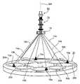
- FIG. 1diagrammatically illustrates one form of braiding apparatus that may be used for making intraluminal implants in accordance with the present invention
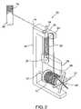
- FIG. 2illustrates one of the driven carriers for one of the filament spools in a commercially available braiding machine which may be used in the apparatus of FIG. 1 , and particularly indicating the span of the filament from its spool towards the braiding point on the mandrel where all the filaments are converged into a braid;
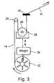
- FIG. 3illustrates a preferred manner of tensioning each of the filaments from its respective spool toward the braiding point in order to produce a uniform tension such as to reduce the possibility of filament rupture or deformation as well as filament entanglement;
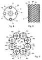
- FIGS. 4 and 5illustrate one loading arrangement for loading the braiding apparatus of FIG. 1 to produce a particular braid pattern, commonly called a Herringbone Pattern, in which each filament of one group of spools is interweaved under and over two filaments of the other group of spools;
- FIG. 6illustrates the Herringbone Pattern produced by the arrangement of FIGS. 4 and 5 ;
- FIGS. 7 and 8illustrate another loading arrangement for producing another broad pattern, commonly called a Diamond Pattern, in which two filaments of one group of spools are interleaved under and over two filaments of the other group of spools;
- FIG. 9illustrates the Diamond Pattern produced by the loading arrangement of FIGS. 7 and 8 ;
- FIGS. 10 and 11illustrate a further loading arrangement for producing another Diamond Pattern in which each filament of one group of spools is interweaved under and over a single filament of the second group of spools;
- FIG. 12illustrates the Diamond Pattern produced by the loading arrangement of FIGS. 10 and 11 ;
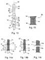
- FIG. 13illustrates the general construction of a mandrel for use in the braiding machine of FIG. 1 to produce tubular braids having flared ends;
- FIGS. 14 a and 14 bdiagrammatically illustrate two manners of cutting the braided tubing applied to the mandrel by the braiding machine in order to cause opposite ends of the braided tube implant device to be outwardly flared, making it particularly useful as an intraluminal implant;
- FIG. 14 cis a diagram helpful in explaining how the outwardly flared end is produced in FIG. 14 b with respect to the cut line at the portion of the tubular braid formed by the small-diameter section of the mandrel;
- FIG. 15illustrates the braided tube implant device after having been cut from the braided tubing in either of the manners illustrated in FIG. 14 a or 14 b;
- FIG. 16illustrates one particular construction of the mandrel of FIG. 13 ;
- FIG. 17illustrates another particular construction of the mandrel of FIG. 13 ;
- FIG. 18 ais a sectional view along line 18 — 18 of FIG. 17 , illustrating a removable ring thereon in its normal operative condition during the formation of the braided tubing thereover;
- FIG. 18 bis a view similar to that of FIG. 18 a , but illustrating the released condition of the ring, produced by manually squeezing it towards a circular configuration, to permit the ring to be conveniently assembled to and removed from the mandrel;
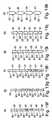
- FIGS. 19 a – 19 killustrate examples of other configurations of mandrels that may be used.
- FIGS. 1–12Braiding Machine Construction
- the inventionis particularly useful when embodied in the “Maypole” type of braiding machine, as sold by Steeger USA, Inc. of Spartanburg, South Carolina, or by the New England Butt Division of Wardwell Braiding Machine Company.
- the inventionis therefore described below with respect to such a braiding machine.
- the inventionis particularly useful, and is therefore also described below, for making braided tubes of ultra-fine filaments, in the order of 50 ⁇ m, for use in medical intraluminal implants, such as stents, filters and diverters, for implantation in the human body. It will be appreciated, as indicated above, that the invention could also be advantageously implemented in other braiding machines and methods, and could be used for making braids for other applications and for other sized filaments.
- FIG. 1diagrammatically illustrates a braiding machine of the foregoing Maypole type. It includes a plurality of carriers divided into two groups, 10 a , 10 b . Each carrier mounts a spool 12 ( FIG. 2 ) carrying supply of a filament 14 to be interwoven into a braid.
- the filaments 14 of all the carriers 10 a , 10 bare converged towards the braiding axis BA through a braiding guide 16 located distally from the plurality of carriers 10 a , 10 b .
- the filaments 14are thus interwoven into a braid 70 about a mandrel 60 passing through the braiding guide 16 .
- the mandrelis generally designated 60 and is more particularly illustrated in FIG. 13
- the braided tube formed thereonis generally designated 70 and is more particularly illustrated in FIGS. 14 a – 14 c below.
- the illustrated apparatusfurther includes an interweaving mechanism housed within a housing generally designated 20 for driving the carriers 10 a , 10 b and for paying out the filaments 14 from their respective spools 12 .
- the filamentsare thus payed out in an interweaving manner towards the braiding guide 16 to form the braid 70 about the mandrel 60 .
- the braiding apparatus illustrated in FIG. 1is of the vertical type; that is, the braiding axis BA of the mandrel 60 , about which the braid 70 is formed, extends in the vertical direction.
- a vertical-type braiding apparatusprovides more convenient access by the operator to various parts of the apparatus than the horizontal-type apparatus wherein the braid is formed about a horizontal axis.
- the interweaving mechanismis within a flat horizontal housing 20 , and includes a drive for driving the two groups of carriers 10 a , 10 b such as to interweave the filaments 14 of their respective spools as they are payed out towards the braiding guide 16 .
- Carriers 10 aare arrayed in a circular array around the braiding axis BA and are driven in one direction about that axis.
- Carriers 10 bare also arrayed, in a circular array around the braiding axis BA, alternatingly with respect to carriers 10 a , and are driven in the opposite direction about that axis.
- FIG. 1illustrates the filaments 14 a payed out from carriers 10 a in full lines, with carriers 10 a being driven about braiding axis BA in the clockwise direction; whereas the filaments 14 b payed out from carriers 10 b , shown in broken lines, with carriers 10 b being driven about braiding axis BA in the counter-clockwise direction.
- the flat horizontal housing 20houses a drive mechanism (to be more particularly described below with respect to FIGS. 4–12 ) which drives carriers 10 a along a circuitous path shown as shaded path 20 a , and drives the carriers 10 b along another circuitous path, shown by unshaded path 20 b , intersecting with the shaded circuitous path 20 a .
- a drive mechanismto be more particularly described below with respect to FIGS. 4–12
- the circuitous path 20 a for carriers 10 aand also the circuitous path 20 b for carriers 10 b , bring the respective carriers 10 a , 10 b radially inwardly and outwardly with respect to the braiding axis BA, as the carriers move around the braiding axis.
- FIG. 2illustrates one structure that may be provided for each of the carriers 10 a , 10 b , mounting one of the spools 12 for the respective filament 14 .
- each carriertherein generally designated 10 , includes a vertically-extending mounting member 22 rotatably mounting the respective filament spool 12 for rotation about a horizontal axis.
- Spool 12could be mounted to rotate with respect to its shaft 12 ′ or could be fixed to its shaft and both rotated with respect to mounting member 22 .
- each carrier mounting member 22mounts an upper roller 24 and a lower roller 26 above the spool 12 , each roller being rotatably mounted about an axis parallel to the spool axis.
- the upper roller 24is rotatably mounted on the carrier mounting member 22 ; whereas the lower roller 26 is rotatably mounted on a movable mounting member 28 which is vertically displaceable with respect to roller 24 and mounting member 22 .
- Each filament 14is fed from its respective spool 12 over the upper roller 24 , and under the lower, vertically-displaceable roller 26 , and through an upper eyelet 30 to braiding guide 16 of FIG. 1 .
- Braiding guide 16converges all the filaments 14 to produce the braid 70 over the mandrel 60 coaxial with the braiding axis BA.
- Braiding machines of this typeusually include a spring arrangement for applying the appropriate tension to the filaments.
- FIG. 2illustrates such a spring, at 32 , applied between the carrier mounting member 22 mounting the upper roller 24 , and the vertically-displaceable mounting member 28 mounting the lower roller 26 . The vertical displacement of mounting member 28 , and thereby of the lower roller 26 , is guided by a rod 34 movable within an opening in the upper roller mounting member 22 .
- FIG. 2further includes the vertically-displaceable mounting member 28 for the lower roller 26 as provided with a depending finger 36 movable within recesses defined by a retainer member 37 fixed to the spool shaft 12 ′ to restrain the spool shaft from free rotation.
- FIG. 3diagrammatically illustrates how the filaments 14 are preferably tensioned in a constant and uniform manner in order to minimize the possibility of over-tensioning likely to cause breakage or deformation, or under-tensioning likely to cause entanglement.
- the vertically displaceable roller 26 in each of the carriers 10is provided with a weight, shown at 39 , which applies a gravitational tensioning force to the filament 14 passing under the lower roller 26 mounted on mounting member 28 . Since this tensioning force is a gravitational force applied by the weight 39 , it is constant and uniform, and does not vary with the circuitous movements of the carriers as in the case where a spring tensioning force is applied to the filaments.
- the braiding machine diagrammatically illustrated in FIG. 1is actually a 16-carrier braiding machine, but is shown half-loaded, i.e., equipped with 8-carriers only divided into the two groups 10 a , 10 b .
- Each of the carriersis driven by a rotor formed with four transfer notches for receiving a carrier at one side and transferring it to another rotor at the opposite side.
- Such rotorsare generally in the form of gears, commonly called horn gears, and are disposed within the flat horizontal housing 20 .
- FIG. 4illustrates one of the horn gears, therein designated 40 . It includes circumferential teeth 42 and four transfer notches or pockets, sometimes called horns 44 , equally spaced around the circumference of the gear.
- FIG. 5illustrates eight of such horn gears 40 arrayed in a circular array around the braiding axis BA and intermeshing with each other so that each horn gear is rotated about its respective axis 46 but in an opposite direction with respect to the adjacent gears on its opposite sides.
- FIG. 5illustrates eight of such horn gears 40 arrayed in a circular array around the braiding axis BA and intermeshing with each other so that each horn gear is rotated about its respective axis 46 but in an opposite direction with respect to the adjacent gears on its opposite sides.
- one group 40 a of alternate horn gearsrotate clockwise about their respective axes 46 a , as shown by arrow 48 a
- the other group 40 b of horn gearsrotate in the opposite direction, e.g., counter-clockwise, about their respective axes 46 b.
- each horn gear 40As well known in braiding machines of this type, the rotation of each horn gear 40 about its respective axis 46 causes a carrier 10 to be received in a notch 44 from the horn gear at one side and to be transferred to the horn gear at the opposite side.
- the arrangementis such that the rotation of the two groups of horn gears 40 a , 40 b in opposite directions around their respective axes 46 a , 46 b is effective to drive the two groups of carriers 10 a , 10 b in opposite directions around the braiding axis BA, and along circuitous paths extending radially inwardly and outwardly with respect to the braiding axis.
- the resultsis to interweave the filaments 14 of the spools 12 carried by the two groups of carriers 10 a , 10 b as the filaments converge at the braiding guide 16 to form the braid 70 around the mandrel 60 .
- the mechanism for rotating the horn gears 40 a , 40 bsuch as to drive the carriers 10 a , 10 b in opposite directions along their respective serpentine paths, is well known in braiding machines of this type, as described for example in the published literature available with respect to the two commercial designs of braiding machines referred to above and incorporated herein by reference.
- Such braiding machinesare capable of producing various types of braid patterns, according to the manner of loading the horn gears 40 .
- three such braiding patternsare described below with respect to FIGS. 4–6 , FIGS. 7–9 , and FIGS. 10–12 , respectively.
- FIGS. 4–6relate to producing a regular braid pattern, which is the most commonly used one, sometimes called a Herringbone Pattern.
- each filament of carriers group 10 ais passed over and under two filaments of carrier group 10 b .
- each horn gear 40is loaded with a carrier 10 as shown in FIG. 4 , namely with alternative notches 44 occupied by a carrier, whereas the remaining alternate notches 44 are not occupied by a carrier.
- FIG. 5illustrates the manner in which the carriers 10 are transferred from one horn gear 40 to the next as each horn gear rotates about its respective axis 46 .
- arrow 48 a in FIG. 5it will be assumed that the horn gears of group 40 a are rotated clockwise about their respective axis 46 a , whereas the horn gears of group 40 b are rotated counter-clockwise about their respective axes 46 b as indicated by arrow 48 b.
- FIG. 6illustrates the braid pattern 51 produced in this set-up, wherein it will be seen that each filament 14 a from the carriers 10 a rotating in one direction about the braiding axis BA is interweaved over two and under two filaments 14 b of the carriers 10 b rotating in the opposite direction around the braiding axis.
- FIG. 7illustrates the set-up of the horn gears 40 for producing a diamond braid pattern, in which two filaments 14 a from carriers 10 a rotating in one direction are interweaved over and under two filaments 14 b from carriers 10 b rotating in the opposite direction.
- FIG. 7illustrates the loading arrangement for the horn gears to produce such a pattern, in which it will be seen that two adjacent notches 44 are loaded with a carrier, whereas the remaining two adjacent notches are not loaded.
- FIG. 8illustrates how the carriers are transferred from one horn gear to the next during the rotation of all the horn gears about their respective axes 46 .
- FIG. 9illustrates the braid pattern 52 so produced, wherein it will be seen that two filaments 14 a from carriers 10 a rotated in the clockwise direction are contiguous and interwoven over and under two contiguous filaments 14 b of the carriers 10 b rotated by the horn gears 40 b in the counter-clockwise direction.
- FIG. 10–12illustrate the manner of producing a braid pattern also of a diamond configuration but in which each filament 14 a from the carriers 10 a is interwoven over and under a single filament 14 b from the carriers 10 b .
- the horn gears 40are loaded with a carrier 10 in only one of the notches 44 , the remaining three notches 44 being without carriers.
- FIG. 12illustrates the braid pattern 53 so produced, wherein it will be seen that each filament 14 a of a carrier 10 a is interwoven over and under each filament 14 b of a carrier 10 b.
- the invention of the present applicationis concerned primarily with the manner of producing flared ends in the braided tubes, and also the construction of the mandrel 60 of FIG. 1 for this purpose.
- the mandrel 60 illustrated in FIG. 1is especially constructed so as to enable the braiding machine as described above with respect to FIGS. 1–12 to be used for producing tubular braid segments 80 having two opposing outwardly flared ends as shown in FIG. 15 , making them especially useful as medical intraluminal implants.
- the mandrel 60 around which the tubular braiding is applied by the braiding machineis of a length many times that of the tubular braid to be produced thereon, therein generally designated 80 in FIG. 15 .
- the mandrel 60is of cylindrical, conical, or tapered configuration and includes a plurality of large-diameter annular sections 62 at spaced locations along the length of the mandrel alternating with small-diameter sections 64 between each pair of large-diameter sections 62 .
- FIG. 13the mandrel 60 around which the tubular braiding is applied by the braiding machine, is of a length many times that of the tubular braid to be produced thereon, therein generally designated 80 in FIG. 15 .
- the mandrel 60is of cylindrical, conical, or tapered configuration and includes a plurality of large-diameter annular sections 62 at spaced locations along the length of the mandrel alternating with small-diameter sections 64 between each pair of large-diameter sections
- each small-diameter section 64 of the mandrelis joined to a large-diameter section 62 by a juncture wall 66 .
- juncture wall 66extends substantially perpendicularly to the longitudinal axis 68 of the mandrel 60 .
- juncture wall 66is defined by a taper or chamfer between large diameter 62 and small diameter 64 , the chamfer being formed by a conical portion of either small diameter section 64 or large diameter section 62 .
- FIG. 13illustrates both the large-diameter section 62 and the small-diameter section 64 as cylindrical in shape, it will be appreciated that either one, or both, may be of conical, oval, or other shape, and that the large-diameter section 62 may be merely a conical flaring at one or both ends of the cylindrical, conical or tapered section 64 .
- FIG. 14 aillustrates the tubular braiding 70 produced on the mandrel 60 ( FIG. 13 ) by the apparatus described above with respect to FIGS. 1–12 . Since such a tubular braiding conforms to the outer surface of the mandrel 60 , the tubular braiding 70 is also in the form of a continuous tube having large-diameter sections 72 of an outer diameter “D” spaced at the opposite ends of small-diameter sections 74 of a diameter “d”. It is understood that diameter “D” and “d” are not fixed and may have variable dimensions along the length of the mandrel and braiding 70 , depending on the width desired and selected.
- the continuous length of tubular braiding 70 illustrated in FIG. 14 ais cut to produce a plurality of the tubular braid segments, shown at 80 in FIG. 15 .
- Each of the tubular braid segments 80 cut from the continuous tubular braiding 70includes a main section 82 having outwardly flared sections 84 , 86 at its opposite ends.
- the continuous tubular braid 70is cut along lines 76 and 78 , in FIG. 14 a , at the large-diameter braid sections 72 .
- FIG. 14 aillustrates the distance “S” between the cut line 76 and 78 is slightly larger than the length “L” of each small-diameter section 64 of the mandrel 60 ( FIG. 13 ).
- the distance “S”may actually be shorter than the mandrel length “L”.
- Cutting the continuous tubes of braiding 70 along the cut lines 76 , 78thus produces an outwardly-flared end 84 , 86 ( FIG. 15 ) at each of the opposite ends of the main section 82 of the braided tube 80 so formed.
- the cut lines 76 , 78may be along mid-lines of the large-diameter sections 72 , in which case the braided tubes 80 produced from the continuous tubular braiding 70 would require little if any trimming.
- the cut lines 76 , 78are not precisely along the mid-lines of the respective large-diameter sections 72 , but are closer to the small-diameter sections 74 , so that some trimming would be required in the tubular braid segments produced from the continuous tubular braiding 70 .
- the flared ends 84 , 86are formed close to the beginning of the transition from the small-diameter sections 74 to the large diameter sections 72 .
- the mandrelis stepped at this transition as shown in FIG. 13 , such that the braid does not actually contact the mandrel at the transition where the cut line is made.
- an appropriate chamfermay be at the diameter transition, and the braid may contact the mandrel along the chamfer.
- FIG. 14 billustrates another manner of cutting the continuous tubular braiding 70 in order to produce individual tubular braid segments 80 outwardly flared at both ends as shown in FIG. 15 .
- one cut 76 ′may be formed in the braided transition region (or in the braided large-diameter region) of the earlier-formed braid to produce the flaring at that end.
- the second cut, shown at 78 ′ in FIG. 14 bmay be at the small-diameter region d in the later-formed braid.
- the ends of the filaments in the tubular braid segment 80 defined by the upper (earlier-formed) side of second cut line 78 ′will flare outwardly because of the release of the stress condition in the filaments as will be described further below.
- tubular braid segment 80flares outwardly along the cut line 78 ′ of FIG. 14 b will be better understood by reference to the diagram of FIG. 14 c.
- cut line 78 ′will produce the other flared end of the tubular braid segment so produced.
- the portion of the braid between cut line 78 ′ and the next cut line 76 ′′may have to be trimmed from the respective tubular braid segment.
- tubular braid segmentsTo enable such tubular braid segments to be used as intraluminal implants, it is important that there be no convergence at either end of the tubular braid segment, since such convergence would interfere with the flow of the blood. Providing some outward flaring at both ends of the tubular braid segment thus assures that there will be no convergence at either end. The amount of outward flaring, however, can vary as desired.
- FIG. 16illustrates a mandrel, therein generally designated 90 , constructed of a plurality of modular units 91 which may be conveniently removable, one after the other, to facilitate the removal of a tubular braid segment 80 of FIG. 15 after having been cut from the continuous tubular braiding 70 formed on the mandrel 90 .
- each modular unit 91includes a cylindrical, conical or tapered section 92 formed at either one or both ends with an enlarged head 93 .
- Each enlarged headcould be formed as a cylindrical, conical or tapered protrusion and with an axially-extending cavity or bore 94 of a diameter to receive the end of the cylindrical, conical or tapered section 92 of another like modular unit 91 .
- mandrel 90is constructed by assembling a plurality of the modular units 91 , with the end of section 92 of each modular unit received within the cavity 94 formed in the enlarged-head of the adjacent modular unit.
- bore 94could extend completely through the respective modular unit 91 to enable a plurality of such modular units to be assembled on a common shaft; also that the modular units could be provided with enlarged heads at both ends of alternatingly cylindrical, conical or tapered sections 92 connecting heads of such units.
- each modular unitis retained within cavity 94 formed in the enlarged head of the next adjacent modular unit 91 by a press-fit, a screw or any other adapter or fastening means. This enables a plurality of such modular units to be conveniently assembled. It further enables each modular unit 91 to be removed one after the other to facilitate the removal of a tubular braid segment 80 after having been cut from the continuous tubular braiding 70 .
- all the modular unitscould be hollow units, or otherwise formed with through openings, for assembling them on an elongated shaft in a manner to enable them to be individually removable to facilitate removal of a tubular braid segment 80 of FIG. 15 after having been cut from the continuous tubular braiding 70 .
- the modular unitsWhen the modular units are assembled on the shaft, they could be retained thereon, e.g., by a press-fit, by fasteners applied to the opposite ends of the shaft, by an adhesive, etc.
- each modular unit 91could be constructed of two separate sections 92 , 93 secured together in any suitable manner. Hollow modular units 91 or modular units with cavities could also be assembled on a non-circular shaft thus enabling efficient cleaning and flushing of gaps between assembled parts.
- FIGS. 17–18 billustrate another construction of mandrel that may be used in order to facilitate the convenient removal of each tubular braid segment 80 after having been cut from the continuous tubular braiding 70 as described above.
- a mandrelgenerally designated 95
- Each of the rings 97is normally of a non-circular configuration, as illustrated in FIG. 18 a , so as to be elastically retained on the cylindrical or conical rod 96 when producing the continuous tubular braiding 70 as described above with respect to FIG. 14 .
- rings 97are designed to be nearly circular when placed on rod 96 .
- the respective elastic ring 97may be manually distorted towards a circular configuration, as shown in FIG. 18 b , by merely squeezing the ring, to permit the ring to be removed, and thereby, to permit the removal of the next tubular braid segment 80 cut from the continuous tubular braiding 70 .
- FIGS. 19 a – 19 killustrate further constructions and configurations that may be used for the mandrel.
- the phrase facing the braiding pointis meant to indicate a taper which after being braided faces, or is tapered towards, the braiding point.
- the phrase facing away from the braiding pointis meant to include a taper that prior to being braided faces away from the braiding point.
- FIGS. 19 a – 19 cshow a cross section of mandrel 95 of FIG. 17 .
- ring 97is cylindrical and in FIG. 19 b ring 97 is conical facing the braiding point.
- FIG. 19 cring 97 is conical facing away from braiding point.
- FIG. 19 d , 19 eshow a cross section of further embodiments of mandrel 90 of FIG. 16 in which enlarged head 93 is cylindrical.
- flare 84 of FIG. 15is formed over enlarged head 93 and cylindrical, conical or tapered section 92 of the same modular unit 91 .
- flare 84 of FIG. 15is formed over enlarged head 93 and cylindrical, conical or tapered section 92 of a connected modular unit 91 .
- FIG. 19 fshows a cross section of a further embodiment of mandrel 90 of FIG. 16 in which enlarged head 93 is conical facing the braiding point and flare 84 of FIG.
- FIG. 19 gshows a cross section of a further embodiment of mandrel 90 of FIG. 16 in which enlarged head 93 and cylindrical or conical section 92 are formed from individual parts connected together.
- FIG. 19 hshows a cross section of a further embodiment of mandrel 90 of FIG. 16 , in which enlarged head 93 is conical facing away from the braiding point; and flare 84 of FIG. 15 is formed over enlarged head 93 and cylindrical, conical or tapered section 92 of the same modular unit 91 .
- FIG. 19 ishows a cross section of a further embodiment of mandrel 90 of FIG.
- FIG. 19 jshows a cross section of a further embodiment of mandrel 90 of FIG. 16 in which enlarged head 93 is cylindrical, flare 84 of FIG. 15 is formed over enlarged head 93 and conical section 92 of the connected modular unit 91 and conical section 92 faces away from the braiding point.
- FIG. 19 kshows a cross section of a further embodiment of mandrel 90 of FIG. 16 in which enlarged head 93 is conical facing the braiding point, flare 84 of FIG. 15 is formed over enlarged head 93 and conical section 92 of the connected modular unit 91 , and conical section 92 faces away from the braiding point.
- a braided intraluminal implantformed on a shaped mandrel, may more closely match the shape of the target implantation area with appropriate oversizing.
- an appropriately shaped braided intraluminal implant, formed on a shaped mandrelmay exhibit improved appositioning and ultimate fixation to the lumen wall.
- Another advantage of a conical, tapered or other shaped mandrelis the ability to change the effective braiding angle over the length of the implant, with a fixed braiding machine pitch.
- the tension, radial force and local stiffness of the implantmay be changed over the length of the implant without changing any braiding machine parameters.
Landscapes
- Engineering & Computer Science (AREA)
- Health & Medical Sciences (AREA)
- Textile Engineering (AREA)
- Biomedical Technology (AREA)
- Life Sciences & Earth Sciences (AREA)
- Transplantation (AREA)
- Heart & Thoracic Surgery (AREA)
- Vascular Medicine (AREA)
- Oral & Maxillofacial Surgery (AREA)
- Animal Behavior & Ethology (AREA)
- General Health & Medical Sciences (AREA)
- Public Health (AREA)
- Veterinary Medicine (AREA)
- Manufacturing & Machinery (AREA)
- Cardiology (AREA)
- Braiding, Manufacturing Of Bobbin-Net Or Lace, And Manufacturing Of Nets By Knotting (AREA)
Abstract
Description
Claims (15)
Priority Applications (1)
| Application Number | Priority Date | Filing Date | Title |
|---|---|---|---|
| US10/862,397US7093527B2 (en) | 2003-06-10 | 2004-06-08 | Method and apparatus for making intraluminal implants and construction particularly useful in such method and apparatus |
Applications Claiming Priority (2)
| Application Number | Priority Date | Filing Date | Title |
|---|---|---|---|
| US47703003P | 2003-06-10 | 2003-06-10 | |
| US10/862,397US7093527B2 (en) | 2003-06-10 | 2004-06-08 | Method and apparatus for making intraluminal implants and construction particularly useful in such method and apparatus |
Publications (2)
| Publication Number | Publication Date |
|---|---|
| US20040254633A1 US20040254633A1 (en) | 2004-12-16 |
| US7093527B2true US7093527B2 (en) | 2006-08-22 |
Family
ID=33514097
Family Applications (1)
| Application Number | Title | Priority Date | Filing Date |
|---|---|---|---|
| US10/862,397Expired - Fee RelatedUS7093527B2 (en) | 2003-06-10 | 2004-06-08 | Method and apparatus for making intraluminal implants and construction particularly useful in such method and apparatus |
Country Status (1)
| Country | Link |
|---|---|
| US (1) | US7093527B2 (en) |
Cited By (95)
| Publication number | Priority date | Publication date | Assignee | Title |
|---|---|---|---|---|
| US20100170990A1 (en)* | 2009-01-07 | 2010-07-08 | Wybrow Tim | Composite spars |
| US20100318178A1 (en)* | 2009-06-15 | 2010-12-16 | Perflow Medical Ltd. | Method and apparatus for allowing blood flow through an occluded vessel |
| US7942925B2 (en) | 2001-07-09 | 2011-05-17 | Surpass Medical Ltd. | Implantable intraluminal device and method of using same in treating aneurysms |
| US20110230955A1 (en)* | 2008-11-24 | 2011-09-22 | Vascular Graft Solutions Ltd. | External stent |
| US8147534B2 (en) | 2005-05-25 | 2012-04-03 | Tyco Healthcare Group Lp | System and method for delivering and deploying an occluding device within a vessel |
| WO2012081020A1 (en) | 2010-12-12 | 2012-06-21 | Perflow Medical Ltd. | Method and apparatus for occlusion retrieval |
| US8210086B2 (en) | 2007-01-22 | 2012-07-03 | A&P Technology, Inc. | Braided reinforcement for aircraft fuselage frames and method of producing the same |
| US8261648B1 (en) | 2011-10-17 | 2012-09-11 | Sequent Medical Inc. | Braiding mechanism and methods of use |
| US8267985B2 (en) | 2005-05-25 | 2012-09-18 | Tyco Healthcare Group Lp | System and method for delivering and deploying an occluding device within a vessel |
| US8273101B2 (en) | 2005-05-25 | 2012-09-25 | Tyco Healthcare Group Lp | System and method for delivering and deploying an occluding device within a vessel |
| US8382825B2 (en) | 2004-05-25 | 2013-02-26 | Covidien Lp | Flexible vascular occluding device |
| US8394119B2 (en) | 2006-02-22 | 2013-03-12 | Covidien Lp | Stents having radiopaque mesh |
| US8398701B2 (en) | 2004-05-25 | 2013-03-19 | Covidien Lp | Flexible vascular occluding device |
| CN103147222A (en)* | 2013-02-26 | 2013-06-12 | 东华大学 | Device capable of realizing braided structure |
| DE102012200584A1 (en)* | 2012-01-17 | 2013-07-18 | Bayerische Motoren Werke Aktiengesellschaft | Method for producing fiber braided fabric on core, involves guiding core through weaving device in braiding point in which fiber material is stored on core, and carrying out alignment of core with feeding device and removal unit |
| US8490530B2 (en)* | 2011-11-23 | 2013-07-23 | Hyundai Motor Company | Plastic composite spring for vehicle suspension and apparatus and method for manufacturing the same |
| US8511214B2 (en) | 2011-04-21 | 2013-08-20 | Aga Medical Corporation | Tubular structure and method for making the same |
| US20130232938A1 (en)* | 2010-11-26 | 2013-09-12 | Daimler Ag | Modular production device for integral fiber semifinished products and method for producing endless-fiber composite components made from integral fiber composite semifinished products having a hollow body structure |
| US20130305465A1 (en)* | 2011-01-27 | 2013-11-21 | Puma SE | Method for producing an upper part of a shoe, in particular of a sports shoe |
| US8617234B2 (en) | 2004-05-25 | 2013-12-31 | Covidien Lp | Flexible vascular occluding device |
| US8623067B2 (en) | 2004-05-25 | 2014-01-07 | Covidien Lp | Methods and apparatus for luminal stenting |
| US20140058436A1 (en)* | 2011-02-18 | 2014-02-27 | Sequent Medical, Inc. | Blood flow disruption devices and methods for the treatment of vascular defects |
| WO2013058889A3 (en)* | 2011-10-17 | 2014-05-08 | Sequent Medical Inc. | Braiding mechanism and methods of use |
| US8728117B1 (en) | 2013-07-29 | 2014-05-20 | Insera Therapeutics, Inc. | Flow disrupting devices |
| US8753371B1 (en) | 2013-03-15 | 2014-06-17 | Insera Therapeutics, Inc. | Woven vascular treatment systems |
| US8911490B2 (en) | 2012-03-27 | 2014-12-16 | Medtronic Vascular, Inc. | Integrated mesh high metal to vessel ratio stent and method |
| US9005270B2 (en) | 2012-03-27 | 2015-04-14 | Medtronic Vascular, Inc. | High metal to vessel ratio stent and method |
| US9034007B2 (en) | 2007-09-21 | 2015-05-19 | Insera Therapeutics, Inc. | Distal embolic protection devices with a variable thickness microguidewire and methods for their use |
| US9114001B2 (en) | 2012-10-30 | 2015-08-25 | Covidien Lp | Systems for attaining a predetermined porosity of a vascular device |
| US9155647B2 (en) | 2012-07-18 | 2015-10-13 | Covidien Lp | Methods and apparatus for luminal stenting |
| US9157174B2 (en) | 2013-02-05 | 2015-10-13 | Covidien Lp | Vascular device for aneurysm treatment and providing blood flow into a perforator vessel |
| WO2015166013A1 (en) | 2014-04-30 | 2015-11-05 | Cerus Endovascular Limited | Occlusion device |
| US9179931B2 (en) | 2013-03-15 | 2015-11-10 | Insera Therapeutics, Inc. | Shape-set textile structure based mechanical thrombectomy systems |
| US9314324B2 (en) | 2013-03-15 | 2016-04-19 | Insera Therapeutics, Inc. | Vascular treatment devices and methods |
| US20160168769A1 (en)* | 2014-12-12 | 2016-06-16 | Woven Orthopedic Technologies, Llc | Methods and systems for manufacturing woven retention devices |
| US9393136B2 (en) | 2012-03-27 | 2016-07-19 | Medtronic Vascular, Inc. | Variable zone high metal to vessel ratio stent and method |
| US20160251786A1 (en)* | 2013-10-18 | 2016-09-01 | Ichikawa Iron Works Co., Ltd. | Thread feeding device for torchon lace machine |
| US9452070B2 (en) | 2012-10-31 | 2016-09-27 | Covidien Lp | Methods and systems for increasing a density of a region of a vascular device |
| US9668544B2 (en) | 2014-12-10 | 2017-06-06 | Nike, Inc. | Last system for articles with braided components |
| US9675482B2 (en) | 2008-05-13 | 2017-06-13 | Covidien Lp | Braid implant delivery systems |
| WO2017153603A1 (en) | 2016-03-11 | 2017-09-14 | Cerus Endovascular Limited | Occlusion device |
| US9808291B2 (en) | 2014-08-05 | 2017-11-07 | Woven Orthopedic Technologies, Llc | Woven retention devices, systems and methods |
| US9839253B2 (en) | 2014-12-10 | 2017-12-12 | Nike, Inc. | Last system for braiding footwear |
| US9907593B2 (en) | 2014-08-05 | 2018-03-06 | Woven Orthopedic Technologies, Llc | Woven retention devices, systems and methods |
| US9920462B2 (en) | 2015-08-07 | 2018-03-20 | Nike, Inc. | Braiding machine with multiple rings of spools |
| US9943351B2 (en) | 2014-09-16 | 2018-04-17 | Woven Orthopedic Technologies, Llc | Woven retention devices, systems, packaging, and related methods |
| US9943427B2 (en) | 2012-11-06 | 2018-04-17 | Covidien Lp | Shaped occluding devices and methods of using the same |
| US10004618B2 (en) | 2004-05-25 | 2018-06-26 | Covidien Lp | Methods and apparatus for luminal stenting |
| US10052218B2 (en) | 2011-04-18 | 2018-08-21 | Vascular Graft Solutions Ltd. | Devices and methods for deploying implantable sleeves over blood vessels |
| US10060057B2 (en) | 2015-05-26 | 2018-08-28 | Nike, Inc. | Braiding machine with non-circular geometry |
| US10238176B2 (en) | 2015-05-26 | 2019-03-26 | Nike, Inc. | Braiding machine and method of forming a braided article using such braiding machine |
| US10280538B2 (en) | 2015-05-26 | 2019-05-07 | Nike, Inc. | Braiding machine and method of forming an article incorporating a moving object |
| US10376274B2 (en) | 2015-07-16 | 2019-08-13 | Perflow Medical Ltd. | Apparatus and method for vessel occlusion removal |
| US10390926B2 (en) | 2013-07-29 | 2019-08-27 | Insera Therapeutics, Inc. | Aspiration devices and methods |
| US10555758B2 (en) | 2015-08-05 | 2020-02-11 | Woven Orthopedic Technologies, Llc | Tapping devices, systems and methods for use in bone tissue |
| US10555581B2 (en) | 2015-05-26 | 2020-02-11 | Nike, Inc. | Braided upper with multiple materials |
| US10674791B2 (en) | 2014-12-10 | 2020-06-09 | Nike, Inc. | Braided article with internal midsole structure |
| US10743618B2 (en) | 2015-05-26 | 2020-08-18 | Nike, Inc. | Hybrid braided article |
| US10806210B2 (en) | 2017-05-31 | 2020-10-20 | Nike, Inc. | Braided articles and methods for their manufacture |
| US10863794B2 (en) | 2013-06-25 | 2020-12-15 | Nike, Inc. | Article of footwear having multiple braided structures |
| US10905430B2 (en) | 2018-01-24 | 2021-02-02 | DePuy Synthes Products, Inc. | Aneurysm device and delivery system |
| US10939915B2 (en) | 2018-05-31 | 2021-03-09 | DePuy Synthes Products, Inc. | Aneurysm device and delivery system |
| US11051573B2 (en) | 2017-05-31 | 2021-07-06 | Nike, Inc. | Braided articles and methods for their manufacture |
| US11058430B2 (en) | 2018-05-25 | 2021-07-13 | DePuy Synthes Products, Inc. | Aneurysm device and delivery system |
| US11076860B2 (en) | 2014-03-31 | 2021-08-03 | DePuy Synthes Products, Inc. | Aneurysm occlusion device |
| US11076861B2 (en) | 2018-10-12 | 2021-08-03 | DePuy Synthes Products, Inc. | Folded aneurysm treatment device and delivery method |
| US11103028B2 (en) | 2015-08-07 | 2021-08-31 | Nike, Inc. | Multi-layered braided article and method of making |
| US11123077B2 (en) | 2018-09-25 | 2021-09-21 | DePuy Synthes Products, Inc. | Intrasaccular device positioning and deployment system |
| US11134953B2 (en) | 2019-02-06 | 2021-10-05 | DePuy Synthes Products, Inc. | Adhesive cover occluding device for aneurysm treatment |
| US11154302B2 (en) | 2014-03-31 | 2021-10-26 | DePuy Synthes Products, Inc. | Aneurysm occlusion device |
| US11202483B2 (en) | 2017-05-31 | 2021-12-21 | Nike, Inc. | Braided articles and methods for their manufacture |
| US11219266B2 (en) | 2013-06-25 | 2022-01-11 | Nike, Inc. | Article of footwear with braided upper |
| US11253261B2 (en) | 2016-03-17 | 2022-02-22 | Swaminathan Jayaraman | Occluding anatomical structures |
| US11272939B2 (en) | 2018-12-18 | 2022-03-15 | DePuy Synthes Products, Inc. | Intrasaccular flow diverter for treating cerebral aneurysms |
| US11278292B2 (en) | 2019-05-21 | 2022-03-22 | DePuy Synthes Products, Inc. | Inverting braided aneurysm treatment system and method |
| US11337706B2 (en) | 2019-03-27 | 2022-05-24 | DePuy Synthes Products, Inc. | Aneurysm treatment device |
| US11395681B2 (en) | 2016-12-09 | 2022-07-26 | Woven Orthopedic Technologies, Llc | Retention devices, lattices and related systems and methods |
| US11406404B2 (en) | 2020-02-20 | 2022-08-09 | Cerus Endovascular Limited | Clot removal distal protection methods |
| US11406392B2 (en) | 2018-12-12 | 2022-08-09 | DePuy Synthes Products, Inc. | Aneurysm occluding device for use with coagulating agents |
| US11413046B2 (en) | 2019-05-21 | 2022-08-16 | DePuy Synthes Products, Inc. | Layered braided aneurysm treatment device |
| US11457926B2 (en) | 2019-12-18 | 2022-10-04 | DePuy Synthes Products, Inc. | Implant having an intrasaccular section and intravascular section |
| US11471162B2 (en) | 2015-12-07 | 2022-10-18 | Cerus Endovascular Limited | Occlusion device |
| US11497504B2 (en) | 2019-05-21 | 2022-11-15 | DePuy Synthes Products, Inc. | Aneurysm treatment with pushable implanted braid |
| US11583282B2 (en) | 2019-05-21 | 2023-02-21 | DePuy Synthes Products, Inc. | Layered braided aneurysm treatment device |
| US11583288B2 (en) | 2018-08-08 | 2023-02-21 | DePuy Synthes Products, Inc. | Delivery of embolic braid |
| US11596412B2 (en) | 2018-05-25 | 2023-03-07 | DePuy Synthes Products, Inc. | Aneurysm device and delivery system |
| US11602350B2 (en) | 2019-12-05 | 2023-03-14 | DePuy Synthes Products, Inc. | Intrasaccular inverting braid with highly flexible fill material |
| US11607226B2 (en) | 2019-05-21 | 2023-03-21 | DePuy Synthes Products, Inc. | Layered braided aneurysm treatment device with corrugations |
| US11672542B2 (en) | 2019-05-21 | 2023-06-13 | DePuy Synthes Products, Inc. | Aneurysm treatment with pushable ball segment |
| US11672543B2 (en) | 2017-02-23 | 2023-06-13 | DePuy Synthes Products, Inc. | Aneurysm method and system |
| US11812971B2 (en) | 2017-08-21 | 2023-11-14 | Cerus Endovascular Limited | Occlusion device |
| US12232737B2 (en) | 2016-03-17 | 2025-02-25 | Eclipse Medical Limited | Occluding anatomical structures |
| US12318294B2 (en) | 2017-07-06 | 2025-06-03 | Raghuveer Basude | Tissue grasping devices and related methods |
| US20250263872A1 (en)* | 2024-02-15 | 2025-08-21 | Rtx Corporation | Extended inner profile for mandrel for use in forming braided cmc structures |
| US12419764B2 (en) | 2018-03-12 | 2025-09-23 | Fluid Biomed Inc. | Bioabsorbable flow diverting scaffold |
Families Citing this family (16)
| Publication number | Priority date | Publication date | Assignee | Title |
|---|---|---|---|---|
| US8561514B2 (en) | 2010-12-14 | 2013-10-22 | Atkins & Pearce, Inc. | Braided carbon nanotube threads and methods of manufacturing the same |
| US9222205B2 (en) | 2013-03-15 | 2015-12-29 | A&P Technology, Inc. | Rapidly configurable braiding machine |
| US11447901B2 (en) | 2013-04-12 | 2022-09-20 | EverestMedica LLC | Method of making a surgical braid |
| US9610077B2 (en) | 2013-08-08 | 2017-04-04 | EverestMedica LLC | Round-flat-round surgical braids |
| CN103835065B (en)* | 2014-03-07 | 2016-01-20 | 江苏神韵绳缆有限公司 | A kind of car formula compiles twisted rope cable machine |
| DE102014009920B4 (en)* | 2014-07-03 | 2021-02-11 | Admedes Schuessler Gmbh | Method for making a body implant and tool therefor |
| US20180065317A1 (en)* | 2016-09-06 | 2018-03-08 | Cc3D Llc | Additive manufacturing system having in-situ fiber splicing |
| US20180065307A1 (en) | 2016-09-06 | 2018-03-08 | Cc3D Llc | Systems and methods for controlling additive manufacturing |
| EP3526379B1 (en) | 2016-10-14 | 2021-08-11 | Inceptus Medical, LLC | Braiding machine and methods of use |
| EP3554391A4 (en) | 2017-02-24 | 2020-09-16 | Inceptus Medical LLC | VESSEL LOCKING DEVICES AND METHODS |
| US11885051B2 (en) | 2017-10-14 | 2024-01-30 | Inceptus Medical, Llc | Braiding machine and methods of use |
| WO2020212972A1 (en)* | 2019-04-14 | 2020-10-22 | Perflow Medical Ltd. | Adaptable device and method for bridging a neck of an aneurysm |
| DE102020101250A1 (en)* | 2020-01-21 | 2021-07-22 | Acandis Gmbh | System and method for braiding a customized stent |
| US11926100B2 (en) | 2020-06-23 | 2024-03-12 | Continuous Composites Inc. | Systems and methods for controlling additive manufacturing |
| US11846049B2 (en)* | 2021-04-23 | 2023-12-19 | The Boeing Company | Braiding apparatus for braiding broad tape |
| CN113550065B (en)* | 2021-07-09 | 2023-03-21 | 艾柯医疗器械(北京)股份有限公司 | Braided tube manufacturing method and tool |
Citations (16)
| Publication number | Priority date | Publication date | Assignee | Title |
|---|---|---|---|---|
| US1064407A (en) | 1910-08-03 | 1913-06-10 | Simon W Wardwell | Braiding-machine. |
| US1423587A (en) | 1919-10-09 | 1922-07-25 | Carl V J Christensen | Yarn retriever for braiding or similar machines |
| US2557816A (en)* | 1949-12-28 | 1951-06-19 | Dominick Di Palma | Mandrel |
| US3287194A (en)* | 1962-04-17 | 1966-11-22 | Dayco Corp | Method of making a flexible corrugated conduit |
| US3783786A (en) | 1972-03-20 | 1974-01-08 | L Ellison | Self-inking hand stamp |
| US4616553A (en) | 1985-02-06 | 1986-10-14 | Nixon Charles E | Fast-moving eyelet guide for a group of braidable strands in a braiding machine |
| US4655771A (en) | 1982-04-30 | 1987-04-07 | Shepherd Patents S.A. | Prosthesis comprising an expansible or contractile tubular body |
| US4846908A (en)* | 1987-04-03 | 1989-07-11 | E. I. Du Pont De Nemours And Company | Process for preparing a fiber reinforced resin matrix preform |
| US4893543A (en)* | 1989-07-05 | 1990-01-16 | Phillips Raymond J | Braiding mandrel for cable grip and strain relief assemblies |
| US5061275A (en) | 1986-04-21 | 1991-10-29 | Medinvent S.A. | Self-expanding prosthesis |
| US5203249A (en)* | 1991-08-30 | 1993-04-20 | United Technologies Corporation | Multiple mandrel/braiding ring braider |
| US5922019A (en) | 1995-11-27 | 1999-07-13 | Schneider (Europe) A.G. | Conical stent |
| US5931077A (en) | 1998-07-10 | 1999-08-03 | Deyoung; Simon A. | Braiding machine eyelet tube support and drive mechanism |
| US5974938A (en) | 1992-06-02 | 1999-11-02 | Lloyd; Carter Francis | Braiding machine |
| US6250193B1 (en)* | 1996-12-02 | 2001-06-26 | A & P Technology, Inc. | Braided structure with elastic bias strands |
| US20020160068A1 (en)* | 2000-01-24 | 2002-10-31 | Takeshi Nakamura | Manufacturing apparatus of fiber reinforced composite member |
- 2004
- 2004-06-08USUS10/862,397patent/US7093527B2/ennot_activeExpired - Fee Related
Patent Citations (22)
| Publication number | Priority date | Publication date | Assignee | Title |
|---|---|---|---|---|
| US1064407A (en) | 1910-08-03 | 1913-06-10 | Simon W Wardwell | Braiding-machine. |
| US1423587A (en) | 1919-10-09 | 1922-07-25 | Carl V J Christensen | Yarn retriever for braiding or similar machines |
| US2557816A (en)* | 1949-12-28 | 1951-06-19 | Dominick Di Palma | Mandrel |
| US3287194A (en)* | 1962-04-17 | 1966-11-22 | Dayco Corp | Method of making a flexible corrugated conduit |
| US3783786A (en) | 1972-03-20 | 1974-01-08 | L Ellison | Self-inking hand stamp |
| US4655771A (en) | 1982-04-30 | 1987-04-07 | Shepherd Patents S.A. | Prosthesis comprising an expansible or contractile tubular body |
| US4655771B1 (en) | 1982-04-30 | 1996-09-10 | Medinvent Ams Sa | Prosthesis comprising an expansible or contractile tubular body |
| US4954126B1 (en) | 1982-04-30 | 1996-05-28 | Ams Med Invent S A | Prosthesis comprising an expansible or contractile tubular body |
| US4954126A (en) | 1982-04-30 | 1990-09-04 | Shepherd Patents S.A. | Prosthesis comprising an expansible or contractile tubular body |
| US4616553A (en) | 1985-02-06 | 1986-10-14 | Nixon Charles E | Fast-moving eyelet guide for a group of braidable strands in a braiding machine |
| US5061275A (en) | 1986-04-21 | 1991-10-29 | Medinvent S.A. | Self-expanding prosthesis |
| US5016516A (en)* | 1987-04-03 | 1991-05-21 | E. I. Du Pont De Nemours And Company | Fiber reinforced resin preform |
| US4846908A (en)* | 1987-04-03 | 1989-07-11 | E. I. Du Pont De Nemours And Company | Process for preparing a fiber reinforced resin matrix preform |
| US4893543A (en)* | 1989-07-05 | 1990-01-16 | Phillips Raymond J | Braiding mandrel for cable grip and strain relief assemblies |
| US5203249A (en)* | 1991-08-30 | 1993-04-20 | United Technologies Corporation | Multiple mandrel/braiding ring braider |
| US5974938A (en) | 1992-06-02 | 1999-11-02 | Lloyd; Carter Francis | Braiding machine |
| US5922019A (en) | 1995-11-27 | 1999-07-13 | Schneider (Europe) A.G. | Conical stent |
| US6283992B1 (en) | 1995-11-27 | 2001-09-04 | Schneider (Europe) Gmbh | Conical stent |
| US6533810B2 (en) | 1995-11-27 | 2003-03-18 | Schneider (Europe) Ag | Conical stent |
| US6250193B1 (en)* | 1996-12-02 | 2001-06-26 | A & P Technology, Inc. | Braided structure with elastic bias strands |
| US5931077A (en) | 1998-07-10 | 1999-08-03 | Deyoung; Simon A. | Braiding machine eyelet tube support and drive mechanism |
| US20020160068A1 (en)* | 2000-01-24 | 2002-10-31 | Takeshi Nakamura | Manufacturing apparatus of fiber reinforced composite member |
Cited By (221)
| Publication number | Priority date | Publication date | Assignee | Title |
|---|---|---|---|---|
| US7942925B2 (en) | 2001-07-09 | 2011-05-17 | Surpass Medical Ltd. | Implantable intraluminal device and method of using same in treating aneurysms |
| US8419787B2 (en) | 2001-11-23 | 2013-04-16 | Surpass Medical Ltd | Implantable intraluminal device and method of using same in treating aneurysms |
| US9801744B2 (en) | 2004-05-25 | 2017-10-31 | Covidien Lp | Methods and apparatus for luminal stenting |
| US10765542B2 (en) | 2004-05-25 | 2020-09-08 | Covidien Lp | Methods and apparatus for luminal stenting |
| US9393021B2 (en) | 2004-05-25 | 2016-07-19 | Covidien Lp | Flexible vascular occluding device |
| US9125659B2 (en) | 2004-05-25 | 2015-09-08 | Covidien Lp | Flexible vascular occluding device |
| US8628564B2 (en) | 2004-05-25 | 2014-01-14 | Covidien Lp | Methods and apparatus for luminal stenting |
| US9295568B2 (en) | 2004-05-25 | 2016-03-29 | Covidien Lp | Methods and apparatus for luminal stenting |
| US8617234B2 (en) | 2004-05-25 | 2013-12-31 | Covidien Lp | Flexible vascular occluding device |
| US12042411B2 (en) | 2004-05-25 | 2024-07-23 | Covidien Lp | Methods and apparatus for luminal stenting |
| US11771433B2 (en) | 2004-05-25 | 2023-10-03 | Covidien Lp | Flexible vascular occluding device |
| US8382825B2 (en) | 2004-05-25 | 2013-02-26 | Covidien Lp | Flexible vascular occluding device |
| US9855047B2 (en) | 2004-05-25 | 2018-01-02 | Covidien Lp | Flexible vascular occluding device |
| US8398701B2 (en) | 2004-05-25 | 2013-03-19 | Covidien Lp | Flexible vascular occluding device |
| US9050205B2 (en) | 2004-05-25 | 2015-06-09 | Covidien Lp | Methods and apparatus for luminal stenting |
| US8623067B2 (en) | 2004-05-25 | 2014-01-07 | Covidien Lp | Methods and apparatus for luminal stenting |
| US10004618B2 (en) | 2004-05-25 | 2018-06-26 | Covidien Lp | Methods and apparatus for luminal stenting |
| US10918389B2 (en) | 2004-05-25 | 2021-02-16 | Covidien Lp | Flexible vascular occluding device |
| US8273101B2 (en) | 2005-05-25 | 2012-09-25 | Tyco Healthcare Group Lp | System and method for delivering and deploying an occluding device within a vessel |
| US8267985B2 (en) | 2005-05-25 | 2012-09-18 | Tyco Healthcare Group Lp | System and method for delivering and deploying an occluding device within a vessel |
| US10064747B2 (en) | 2005-05-25 | 2018-09-04 | Covidien Lp | System and method for delivering and deploying an occluding device within a vessel |
| US9204983B2 (en) | 2005-05-25 | 2015-12-08 | Covidien Lp | System and method for delivering and deploying an occluding device within a vessel |
| US8257421B2 (en) | 2005-05-25 | 2012-09-04 | Tyco Healthcare Group Lp | System and method for delivering and deploying an occluding device within a vessel |
| US9381104B2 (en) | 2005-05-25 | 2016-07-05 | Covidien Lp | System and method for delivering and deploying an occluding device within a vessel |
| US8236042B2 (en) | 2005-05-25 | 2012-08-07 | Tyco Healthcare Group Lp | System and method for delivering and deploying an occluding device within a vessel |
| US9198666B2 (en) | 2005-05-25 | 2015-12-01 | Covidien Lp | System and method for delivering and deploying an occluding device within a vessel |
| US10322018B2 (en) | 2005-05-25 | 2019-06-18 | Covidien Lp | System and method for delivering and deploying an occluding device within a vessel |
| US8147534B2 (en) | 2005-05-25 | 2012-04-03 | Tyco Healthcare Group Lp | System and method for delivering and deploying an occluding device within a vessel |
| US9095343B2 (en) | 2005-05-25 | 2015-08-04 | Covidien Lp | System and method for delivering and deploying an occluding device within a vessel |
| US9610181B2 (en) | 2006-02-22 | 2017-04-04 | Covidien Lp | Stents having radiopaque mesh |
| US9320590B2 (en) | 2006-02-22 | 2016-04-26 | Covidien Lp | Stents having radiopaque mesh |
| US11382777B2 (en) | 2006-02-22 | 2022-07-12 | Covidien Lp | Stents having radiopaque mesh |
| US10433988B2 (en) | 2006-02-22 | 2019-10-08 | Covidien Lp | Stents having radiopaque mesh |
| US8394119B2 (en) | 2006-02-22 | 2013-03-12 | Covidien Lp | Stents having radiopaque mesh |
| US8210086B2 (en) | 2007-01-22 | 2012-07-03 | A&P Technology, Inc. | Braided reinforcement for aircraft fuselage frames and method of producing the same |
| US9034007B2 (en) | 2007-09-21 | 2015-05-19 | Insera Therapeutics, Inc. | Distal embolic protection devices with a variable thickness microguidewire and methods for their use |
| US9675482B2 (en) | 2008-05-13 | 2017-06-13 | Covidien Lp | Braid implant delivery systems |
| US11707371B2 (en) | 2008-05-13 | 2023-07-25 | Covidien Lp | Braid implant delivery systems |
| US10610389B2 (en) | 2008-05-13 | 2020-04-07 | Covidien Lp | Braid implant delivery systems |
| US20110230955A1 (en)* | 2008-11-24 | 2011-09-22 | Vascular Graft Solutions Ltd. | External stent |
| US8734503B2 (en) | 2008-11-24 | 2014-05-27 | Vascular Graft Solutions Ltd. | External stent |
| US9949852B2 (en) | 2008-11-24 | 2018-04-24 | Vascular Graft Solutions Ltd. | Implant for supporting bodily conduits such as blood vessels or/and grafted vessels |
| US9265632B2 (en) | 2008-11-24 | 2016-02-23 | Vascular Graft Solutions Ltd. | Methods of supporting a vein |
| US8061253B2 (en)* | 2009-01-07 | 2011-11-22 | Ge Aviation Systems Limited | Composite spars |
| US20100170990A1 (en)* | 2009-01-07 | 2010-07-08 | Wybrow Tim | Composite spars |
| US8636760B2 (en) | 2009-04-20 | 2014-01-28 | Covidien Lp | System and method for delivering and deploying an occluding device within a vessel |
| US9278201B2 (en) | 2009-06-15 | 2016-03-08 | Perflow Medical Ltd. | Method and apparatus for allowing blood flow through an occluded vessel |
| US11179253B2 (en) | 2009-06-15 | 2021-11-23 | Perflow Medieal Ltd. | Method and apparatus for allowing blood flow through an occluded vessel |
| US9510855B2 (en) | 2009-06-15 | 2016-12-06 | Perflow Medical Ltd. | Method and apparatus for allowing blood flow through an occluded vessel |
| WO2010146581A1 (en) | 2009-06-15 | 2010-12-23 | Perflow Medical Ltd. | Method and apparatus for allowing blood flow through an occluded vessel |
| US20100318178A1 (en)* | 2009-06-15 | 2010-12-16 | Perflow Medical Ltd. | Method and apparatus for allowing blood flow through an occluded vessel |
| US9156235B2 (en)* | 2010-11-26 | 2015-10-13 | Daimler Ag | Modular production device for integral fiber semifinished products and method for producing endless-fiber composite components made from integral fiber composite semifinished products having a hollow body structure |
| US20130232938A1 (en)* | 2010-11-26 | 2013-09-12 | Daimler Ag | Modular production device for integral fiber semifinished products and method for producing endless-fiber composite components made from integral fiber composite semifinished products having a hollow body structure |
| WO2012081020A1 (en) | 2010-12-12 | 2012-06-21 | Perflow Medical Ltd. | Method and apparatus for occlusion retrieval |
| US8757038B2 (en)* | 2011-01-27 | 2014-06-24 | Puma SE | Method for producing an upper part of a shoe, in particular of a sports shoe |
| US20130305465A1 (en)* | 2011-01-27 | 2013-11-21 | Puma SE | Method for producing an upper part of a shoe, in particular of a sports shoe |
| US20140058436A1 (en)* | 2011-02-18 | 2014-02-27 | Sequent Medical, Inc. | Blood flow disruption devices and methods for the treatment of vascular defects |
| US10052218B2 (en) | 2011-04-18 | 2018-08-21 | Vascular Graft Solutions Ltd. | Devices and methods for deploying implantable sleeves over blood vessels |
| US8511214B2 (en) | 2011-04-21 | 2013-08-20 | Aga Medical Corporation | Tubular structure and method for making the same |
| US8919389B2 (en) | 2011-04-21 | 2014-12-30 | Aga Medical Corporation | Tubular structure and method for making the same |
| US8826791B2 (en) | 2011-10-17 | 2014-09-09 | Sequent Medical, Inc. | Braiding mechanism and methods of use |
| US10260182B2 (en) | 2011-10-17 | 2019-04-16 | Sequent Medical, Inc. | Braiding mechanism and methods of use |
| US11352724B2 (en) | 2011-10-17 | 2022-06-07 | Sequent Medical, Inc. | Braiding mechanism and methods of use |
| US11885053B2 (en) | 2011-10-17 | 2024-01-30 | Microvention, Inc. | Braiding mechanism and methods of use |
| CN106192198A (en)* | 2011-10-17 | 2016-12-07 | 后续医疗股份有限公司 | Knitting mechanism |
| US9631303B2 (en) | 2011-10-17 | 2017-04-25 | Sequent Medical, Inc. | Braiding mechanism and methods of use |
| US8261648B1 (en) | 2011-10-17 | 2012-09-11 | Sequent Medical Inc. | Braiding mechanism and methods of use |
| US8820207B2 (en) | 2011-10-17 | 2014-09-02 | Sequent Medical, Inc. | Braiding mechanism and methods of use |
| WO2013058889A3 (en)* | 2011-10-17 | 2014-05-08 | Sequent Medical Inc. | Braiding mechanism and methods of use |
| US9528205B2 (en) | 2011-10-17 | 2016-12-27 | Sequent Medical, Inc | Braiding mechanism and methods of use |
| US10260183B2 (en) | 2011-10-17 | 2019-04-16 | Sequent Medical, Inc. | Braiding mechanism and methods of use |
| US8430012B1 (en) | 2011-10-17 | 2013-04-30 | Sequent Medical Inc. | Braiding mechanism and methods of use |
| US10907283B2 (en) | 2011-10-17 | 2021-02-02 | Sequent Medical, Inc. | Braiding mechanism and methods of use |
| US12344975B2 (en) | 2011-10-17 | 2025-07-01 | Microvention, Inc. | Braiding mechanism and methods of use |
| US8833224B2 (en) | 2011-10-17 | 2014-09-16 | Sequent Medical, Inc. | Braiding mechanism and methods of use |
| US8490530B2 (en)* | 2011-11-23 | 2013-07-23 | Hyundai Motor Company | Plastic composite spring for vehicle suspension and apparatus and method for manufacturing the same |
| DE102012200584A1 (en)* | 2012-01-17 | 2013-07-18 | Bayerische Motoren Werke Aktiengesellschaft | Method for producing fiber braided fabric on core, involves guiding core through weaving device in braiding point in which fiber material is stored on core, and carrying out alignment of core with feeding device and removal unit |
| US9005270B2 (en) | 2012-03-27 | 2015-04-14 | Medtronic Vascular, Inc. | High metal to vessel ratio stent and method |
| US9393136B2 (en) | 2012-03-27 | 2016-07-19 | Medtronic Vascular, Inc. | Variable zone high metal to vessel ratio stent and method |
| US8911490B2 (en) | 2012-03-27 | 2014-12-16 | Medtronic Vascular, Inc. | Integrated mesh high metal to vessel ratio stent and method |
| US9155647B2 (en) | 2012-07-18 | 2015-10-13 | Covidien Lp | Methods and apparatus for luminal stenting |
| US9877856B2 (en) | 2012-07-18 | 2018-01-30 | Covidien Lp | Methods and apparatus for luminal stenting |
| US9114001B2 (en) | 2012-10-30 | 2015-08-25 | Covidien Lp | Systems for attaining a predetermined porosity of a vascular device |
| US9301831B2 (en) | 2012-10-30 | 2016-04-05 | Covidien Lp | Methods for attaining a predetermined porosity of a vascular device |
| US9907643B2 (en) | 2012-10-30 | 2018-03-06 | Covidien Lp | Systems for attaining a predetermined porosity of a vascular device |
| US9452070B2 (en) | 2012-10-31 | 2016-09-27 | Covidien Lp | Methods and systems for increasing a density of a region of a vascular device |
| US10206798B2 (en) | 2012-10-31 | 2019-02-19 | Covidien Lp | Methods and systems for increasing a density of a region of a vascular device |
| US10952878B2 (en) | 2012-10-31 | 2021-03-23 | Covidien Lp | Methods and systems for increasing a density of a region of a vascular device |
| US9943427B2 (en) | 2012-11-06 | 2018-04-17 | Covidien Lp | Shaped occluding devices and methods of using the same |
| US9561122B2 (en) | 2013-02-05 | 2017-02-07 | Covidien Lp | Vascular device for aneurysm treatment and providing blood flow into a perforator vessel |
| US9157174B2 (en) | 2013-02-05 | 2015-10-13 | Covidien Lp | Vascular device for aneurysm treatment and providing blood flow into a perforator vessel |
| CN103147222A (en)* | 2013-02-26 | 2013-06-12 | 东华大学 | Device capable of realizing braided structure |
| US20140265096A1 (en)* | 2013-03-15 | 2014-09-18 | Insera Therapeutics, Inc. | Non-cylindrical mandrels |
| US9833251B2 (en) | 2013-03-15 | 2017-12-05 | Insera Therapeutics, Inc. | Variably bulbous vascular treatment devices |
| US9314324B2 (en) | 2013-03-15 | 2016-04-19 | Insera Therapeutics, Inc. | Vascular treatment devices and methods |
| US8783151B1 (en)* | 2013-03-15 | 2014-07-22 | Insera Therapeutics, Inc. | Methods of manufacturing vascular treatment devices |
| US8789452B1 (en)* | 2013-03-15 | 2014-07-29 | Insera Therapeutics, Inc. | Methods of manufacturing woven vascular treatment devices |
| US11298144B2 (en) | 2013-03-15 | 2022-04-12 | Insera Therapeutics, Inc. | Thrombus aspiration facilitation systems |
| US10463468B2 (en) | 2013-03-15 | 2019-11-05 | Insera Therapeutics, Inc. | Thrombus aspiration with different intensity levels |
| US9592068B2 (en) | 2013-03-15 | 2017-03-14 | Insera Therapeutics, Inc. | Free end vascular treatment systems |
| US9179995B2 (en) | 2013-03-15 | 2015-11-10 | Insera Therapeutics, Inc. | Methods of manufacturing slotted vascular treatment devices |
| US9179931B2 (en) | 2013-03-15 | 2015-11-10 | Insera Therapeutics, Inc. | Shape-set textile structure based mechanical thrombectomy systems |
| US10251739B2 (en) | 2013-03-15 | 2019-04-09 | Insera Therapeutics, Inc. | Thrombus aspiration using an operator-selectable suction pattern |
| US20140260928A1 (en)* | 2013-03-15 | 2014-09-18 | Insera Therapeutics, Inc. | Methods of using non-cylindrical mandrels |
| US9750524B2 (en) | 2013-03-15 | 2017-09-05 | Insera Therapeutics, Inc. | Shape-set textile structure based mechanical thrombectomy systems |
| US8852227B1 (en) | 2013-03-15 | 2014-10-07 | Insera Therapeutics, Inc. | Woven radiopaque patterns |
| US10335260B2 (en) | 2013-03-15 | 2019-07-02 | Insera Therapeutics, Inc. | Methods of treating a thrombus in a vein using cyclical aspiration patterns |
| US10342655B2 (en) | 2013-03-15 | 2019-07-09 | Insera Therapeutics, Inc. | Methods of treating a thrombus in an artery using cyclical aspiration patterns |
| US8753371B1 (en) | 2013-03-15 | 2014-06-17 | Insera Therapeutics, Inc. | Woven vascular treatment systems |
| US8910555B2 (en)* | 2013-03-15 | 2014-12-16 | Insera Therapeutics, Inc. | Non-cylindrical mandrels |
| US8904914B2 (en)* | 2013-03-15 | 2014-12-09 | Insera Therapeutics, Inc. | Methods of using non-cylindrical mandrels |
| US8895891B2 (en)* | 2013-03-15 | 2014-11-25 | Insera Therapeutics, Inc. | Methods of cutting tubular devices |
| US9901435B2 (en) | 2013-03-15 | 2018-02-27 | Insera Therapeutics, Inc. | Longitudinally variable vascular treatment devices |
| US8882797B2 (en) | 2013-03-15 | 2014-11-11 | Insera Therapeutics, Inc. | Methods of embolic filtering |
| US10863794B2 (en) | 2013-06-25 | 2020-12-15 | Nike, Inc. | Article of footwear having multiple braided structures |
| US11219266B2 (en) | 2013-06-25 | 2022-01-11 | Nike, Inc. | Article of footwear with braided upper |
| US8863631B1 (en)* | 2013-07-29 | 2014-10-21 | Insera Therapeutics, Inc. | Methods of manufacturing flow diverting devices |
| US8932320B1 (en) | 2013-07-29 | 2015-01-13 | Insera Therapeutics, Inc. | Methods of aspirating thrombi |
| US8845678B1 (en) | 2013-07-29 | 2014-09-30 | Insera Therapeutics Inc. | Two-way shape memory vascular treatment methods |
| US8728117B1 (en) | 2013-07-29 | 2014-05-20 | Insera Therapeutics, Inc. | Flow disrupting devices |
| US8728116B1 (en) | 2013-07-29 | 2014-05-20 | Insera Therapeutics, Inc. | Slotted catheters |
| US8866049B1 (en) | 2013-07-29 | 2014-10-21 | Insera Therapeutics, Inc. | Methods of selectively heat treating tubular devices |
| US8735777B1 (en) | 2013-07-29 | 2014-05-27 | Insera Therapeutics, Inc. | Heat treatment systems |
| US8845679B1 (en) | 2013-07-29 | 2014-09-30 | Insera Therapeutics, Inc. | Variable porosity flow diverting devices |
| US8870910B1 (en) | 2013-07-29 | 2014-10-28 | Insera Therapeutics, Inc. | Methods of decoupling joints |
| US8784446B1 (en) | 2013-07-29 | 2014-07-22 | Insera Therapeutics, Inc. | Circumferentially offset variable porosity devices |
| US8790365B1 (en) | 2013-07-29 | 2014-07-29 | Insera Therapeutics, Inc. | Fistula flow disruptor methods |
| US10751159B2 (en) | 2013-07-29 | 2020-08-25 | Insera Therapeutics, Inc. | Systems for aspirating thrombus during neurosurgical procedures |
| US8870901B1 (en) | 2013-07-29 | 2014-10-28 | Insera Therapeutics, Inc. | Two-way shape memory vascular treatment systems |
| US8795330B1 (en) | 2013-07-29 | 2014-08-05 | Insera Therapeutics, Inc. | Fistula flow disruptors |
| US8803030B1 (en) | 2013-07-29 | 2014-08-12 | Insera Therapeutics, Inc. | Devices for slag removal |
| US8816247B1 (en) | 2013-07-29 | 2014-08-26 | Insera Therapeutics, Inc. | Methods for modifying hypotubes |
| US8828045B1 (en) | 2013-07-29 | 2014-09-09 | Insera Therapeutics, Inc. | Balloon catheters |
| US8859934B1 (en) | 2013-07-29 | 2014-10-14 | Insera Therapeutics, Inc. | Methods for slag removal |
| US8932321B1 (en) | 2013-07-29 | 2015-01-13 | Insera Therapeutics, Inc. | Aspiration systems |
| US8813625B1 (en)* | 2013-07-29 | 2014-08-26 | Insera Therapeutics, Inc. | Methods of manufacturing variable porosity flow diverting devices |
| US8872068B1 (en) | 2013-07-29 | 2014-10-28 | Insera Therapeutics, Inc. | Devices for modifying hypotubes |
| US10390926B2 (en) | 2013-07-29 | 2019-08-27 | Insera Therapeutics, Inc. | Aspiration devices and methods |
| US8869670B1 (en) | 2013-07-29 | 2014-10-28 | Insera Therapeutics, Inc. | Methods of manufacturing variable porosity devices |
| US20160251786A1 (en)* | 2013-10-18 | 2016-09-01 | Ichikawa Iron Works Co., Ltd. | Thread feeding device for torchon lace machine |
| US10208411B2 (en)* | 2013-10-18 | 2019-02-19 | Ichikawa Iron Works Co., Ltd. | Thread feeding device for torchon lace machine |
| US11154302B2 (en) | 2014-03-31 | 2021-10-26 | DePuy Synthes Products, Inc. | Aneurysm occlusion device |
| US11076860B2 (en) | 2014-03-31 | 2021-08-03 | DePuy Synthes Products, Inc. | Aneurysm occlusion device |
| US11284901B2 (en) | 2014-04-30 | 2022-03-29 | Cerus Endovascular Limited | Occlusion device |
| EP3970635A1 (en) | 2014-04-30 | 2022-03-23 | Cerus Endovascular Limited | Occlusion device |
| EP3510945A1 (en) | 2014-04-30 | 2019-07-17 | Cerus Endovascular Limited | Occlusion device |
| WO2015166013A1 (en) | 2014-04-30 | 2015-11-05 | Cerus Endovascular Limited | Occlusion device |
| US11389174B2 (en) | 2014-04-30 | 2022-07-19 | Cerus Endovascular Limited | Occlusion device |
| US10130372B2 (en) | 2014-04-30 | 2018-11-20 | Cerus Endovascular Limited | Occlusion Device |
| US12029431B2 (en) | 2014-04-30 | 2024-07-09 | Stryker Ireland Technology, Ltd. | Occlusion device |
| US12414775B1 (en) | 2014-04-30 | 2025-09-16 | Stryker Ireland Technology LTD | Occlusion device |
| US10588677B2 (en) | 2014-08-05 | 2020-03-17 | Woven Orthopedic Technologies, Llc | Woven retention devices, systems and methods |
| US11376051B2 (en) | 2014-08-05 | 2022-07-05 | Woven Orthopedic Technologies, Llc | Woven retention devices, systems and methods |
| US9907593B2 (en) | 2014-08-05 | 2018-03-06 | Woven Orthopedic Technologies, Llc | Woven retention devices, systems and methods |
| US9808291B2 (en) | 2014-08-05 | 2017-11-07 | Woven Orthopedic Technologies, Llc | Woven retention devices, systems and methods |
| US9943351B2 (en) | 2014-09-16 | 2018-04-17 | Woven Orthopedic Technologies, Llc | Woven retention devices, systems, packaging, and related methods |
| US11540596B2 (en) | 2014-12-10 | 2023-01-03 | Nike, Inc. | Last system for articles with braided components |
| US10299544B2 (en) | 2014-12-10 | 2019-05-28 | Nike, Inc. | Last system for articles with braided components |
| US10932528B2 (en) | 2014-12-10 | 2021-03-02 | Nike, Inc. | Last system for articles with braided components |
| US9839253B2 (en) | 2014-12-10 | 2017-12-12 | Nike, Inc. | Last system for braiding footwear |
| US12042022B2 (en) | 2014-12-10 | 2024-07-23 | Nike, Inc. | Last system for articles with braided components |
| US9668544B2 (en) | 2014-12-10 | 2017-06-06 | Nike, Inc. | Last system for articles with braided components |
| US10674791B2 (en) | 2014-12-10 | 2020-06-09 | Nike, Inc. | Braided article with internal midsole structure |
| US20160168769A1 (en)* | 2014-12-12 | 2016-06-16 | Woven Orthopedic Technologies, Llc | Methods and systems for manufacturing woven retention devices |
| US10238176B2 (en) | 2015-05-26 | 2019-03-26 | Nike, Inc. | Braiding machine and method of forming a braided article using such braiding machine |
| US10060057B2 (en) | 2015-05-26 | 2018-08-28 | Nike, Inc. | Braiding machine with non-circular geometry |
| US11339513B2 (en) | 2015-05-26 | 2022-05-24 | Nike, Inc. | Braiding machine and method of forming an article incorporating a moving object |
| US10280538B2 (en) | 2015-05-26 | 2019-05-07 | Nike, Inc. | Braiding machine and method of forming an article incorporating a moving object |
| US10743618B2 (en) | 2015-05-26 | 2020-08-18 | Nike, Inc. | Hybrid braided article |
| US10870933B2 (en) | 2015-05-26 | 2020-12-22 | Nike, Inc. | Braiding machine and method of forming an article incorporating a moving object |
| US10555581B2 (en) | 2015-05-26 | 2020-02-11 | Nike, Inc. | Braided upper with multiple materials |
| US11129631B2 (en) | 2015-07-16 | 2021-09-28 | Perflow Medical Ltd. | Apparatus and method for vessel occlusion removal |
| US10376274B2 (en) | 2015-07-16 | 2019-08-13 | Perflow Medical Ltd. | Apparatus and method for vessel occlusion removal |
| US10555758B2 (en) | 2015-08-05 | 2020-02-11 | Woven Orthopedic Technologies, Llc | Tapping devices, systems and methods for use in bone tissue |
| US9920462B2 (en) | 2015-08-07 | 2018-03-20 | Nike, Inc. | Braiding machine with multiple rings of spools |
| US11103028B2 (en) | 2015-08-07 | 2021-08-31 | Nike, Inc. | Multi-layered braided article and method of making |
| US12076022B2 (en) | 2015-12-07 | 2024-09-03 | Stryker Ireland Technology Ltd. | Occlusion device |
| US11471162B2 (en) | 2015-12-07 | 2022-10-18 | Cerus Endovascular Limited | Occlusion device |
| WO2017153603A1 (en) | 2016-03-11 | 2017-09-14 | Cerus Endovascular Limited | Occlusion device |
| US11648013B2 (en) | 2016-03-11 | 2023-05-16 | Cerus Endovascular Limited | Occlusion device |
| US10869672B2 (en) | 2016-03-11 | 2020-12-22 | Cents Endovascular Limited | Occlusion device |
| EP3782576A1 (en) | 2016-03-11 | 2021-02-24 | Cerus Endovascular Limited | Occlusion device |
| US12285175B2 (en) | 2016-03-11 | 2025-04-29 | Stryker Ireland Technology Ltd. | Occlusion device |
| US11253261B2 (en) | 2016-03-17 | 2022-02-22 | Swaminathan Jayaraman | Occluding anatomical structures |
| US12232737B2 (en) | 2016-03-17 | 2025-02-25 | Eclipse Medical Limited | Occluding anatomical structures |
| US11395681B2 (en) | 2016-12-09 | 2022-07-26 | Woven Orthopedic Technologies, Llc | Retention devices, lattices and related systems and methods |
| US11890020B2 (en) | 2017-02-23 | 2024-02-06 | DePuy Synthes Products, Inc. | Intrasaccular aneurysm treatment device with varying coatings |
| US11672543B2 (en) | 2017-02-23 | 2023-06-13 | DePuy Synthes Products, Inc. | Aneurysm method and system |
| US10806210B2 (en) | 2017-05-31 | 2020-10-20 | Nike, Inc. | Braided articles and methods for their manufacture |
| US11202483B2 (en) | 2017-05-31 | 2021-12-21 | Nike, Inc. | Braided articles and methods for their manufacture |
| US11425956B2 (en) | 2017-05-31 | 2022-08-30 | Nike, Inc. | Braided articles and methods for their manufacture |
| US11051573B2 (en) | 2017-05-31 | 2021-07-06 | Nike, Inc. | Braided articles and methods for their manufacture |
| US12318294B2 (en) | 2017-07-06 | 2025-06-03 | Raghuveer Basude | Tissue grasping devices and related methods |
| US12251112B2 (en) | 2017-08-21 | 2025-03-18 | Stryker Ireland Technology Ltd. | Occlusion device |
| US11812971B2 (en) | 2017-08-21 | 2023-11-14 | Cerus Endovascular Limited | Occlusion device |
| US11672540B2 (en) | 2018-01-24 | 2023-06-13 | DePuy Synthes Products, Inc. | Aneurysm device and delivery system |
| US10905430B2 (en) | 2018-01-24 | 2021-02-02 | DePuy Synthes Products, Inc. | Aneurysm device and delivery system |
| US12419764B2 (en) | 2018-03-12 | 2025-09-23 | Fluid Biomed Inc. | Bioabsorbable flow diverting scaffold |
| US11596412B2 (en) | 2018-05-25 | 2023-03-07 | DePuy Synthes Products, Inc. | Aneurysm device and delivery system |
| US11058430B2 (en) | 2018-05-25 | 2021-07-13 | DePuy Synthes Products, Inc. | Aneurysm device and delivery system |
| US10939915B2 (en) | 2018-05-31 | 2021-03-09 | DePuy Synthes Products, Inc. | Aneurysm device and delivery system |
| US12150650B2 (en) | 2018-08-08 | 2024-11-26 | DePuy Synthes Products, Inc. | Delivery of embolic braid |
| US11583288B2 (en) | 2018-08-08 | 2023-02-21 | DePuy Synthes Products, Inc. | Delivery of embolic braid |
| US11123077B2 (en) | 2018-09-25 | 2021-09-21 | DePuy Synthes Products, Inc. | Intrasaccular device positioning and deployment system |
| US11633191B2 (en) | 2018-10-12 | 2023-04-25 | DePuy Synthes Products, Inc. | Folded aneurysm treatment device and delivery method |
| US11076861B2 (en) | 2018-10-12 | 2021-08-03 | DePuy Synthes Products, Inc. | Folded aneurysm treatment device and delivery method |
| US11406392B2 (en) | 2018-12-12 | 2022-08-09 | DePuy Synthes Products, Inc. | Aneurysm occluding device for use with coagulating agents |
| US11272939B2 (en) | 2018-12-18 | 2022-03-15 | DePuy Synthes Products, Inc. | Intrasaccular flow diverter for treating cerebral aneurysms |
| US11134953B2 (en) | 2019-02-06 | 2021-10-05 | DePuy Synthes Products, Inc. | Adhesive cover occluding device for aneurysm treatment |
| US11337706B2 (en) | 2019-03-27 | 2022-05-24 | DePuy Synthes Products, Inc. | Aneurysm treatment device |
| US11607226B2 (en) | 2019-05-21 | 2023-03-21 | DePuy Synthes Products, Inc. | Layered braided aneurysm treatment device with corrugations |
| US11583282B2 (en) | 2019-05-21 | 2023-02-21 | DePuy Synthes Products, Inc. | Layered braided aneurysm treatment device |
| US11672542B2 (en) | 2019-05-21 | 2023-06-13 | DePuy Synthes Products, Inc. | Aneurysm treatment with pushable ball segment |
| US11413046B2 (en) | 2019-05-21 | 2022-08-16 | DePuy Synthes Products, Inc. | Layered braided aneurysm treatment device |
| US11278292B2 (en) | 2019-05-21 | 2022-03-22 | DePuy Synthes Products, Inc. | Inverting braided aneurysm treatment system and method |
| US11497504B2 (en) | 2019-05-21 | 2022-11-15 | DePuy Synthes Products, Inc. | Aneurysm treatment with pushable implanted braid |
| US11602350B2 (en) | 2019-12-05 | 2023-03-14 | DePuy Synthes Products, Inc. | Intrasaccular inverting braid with highly flexible fill material |
| US11457926B2 (en) | 2019-12-18 | 2022-10-04 | DePuy Synthes Products, Inc. | Implant having an intrasaccular section and intravascular section |
| US11406404B2 (en) | 2020-02-20 | 2022-08-09 | Cerus Endovascular Limited | Clot removal distal protection methods |
| US12303153B2 (en) | 2020-02-20 | 2025-05-20 | Stryker Ireland Technology Ltd. | Clot removal distal protection methods |
| US20250263872A1 (en)* | 2024-02-15 | 2025-08-21 | Rtx Corporation | Extended inner profile for mandrel for use in forming braided cmc structures |
Also Published As
| Publication number | Publication date |
|---|---|
| US20040254633A1 (en) | 2004-12-16 |
Similar Documents
| Publication | Publication Date | Title |
|---|---|---|
| US7093527B2 (en) | Method and apparatus for making intraluminal implants and construction particularly useful in such method and apparatus | |
| EP1560544B1 (en) | Braided stent and method for its manufacture technical field | |
| US10716549B2 (en) | Medical device for treating a target site | |
| US7275471B2 (en) | Mixed wire braided device with structural integrity | |
| US6237460B1 (en) | Method for preparation of a self-expanding stent for a medical device to be introduced into a cavity of a body | |
| US9631303B2 (en) | Braiding mechanism and methods of use | |
| JP2006506168A5 (en) | ||
| US6161399A (en) | Process for manufacturing a wire reinforced monolayer fabric stent | |
| KR20140019286A (en) | Implant for influencing the blood flow in arteriovenous malformations | |
| CN108601596B (en) | Implants | |
| JP2014519353A (en) | Tubular structure and manufacturing method thereof | |
| JP2003521312A (en) | Braided-branch stent, method of treating a lumen using the same, and method of manufacturing the same | |
| JP2017511203A5 (en) | ||
| WO2016094678A1 (en) | Methods and systems for manufacturing woven retention devices | |
| US2388693A (en) | Method and machine for making catheters | |
| KR100776686B1 (en) | Braided Stent and Manufacturing Method Thereof | |
| US20040186549A1 (en) | Braided stent with looped ends and method for making same | |
| CN218932506U (en) | Braiding equipment for manufacturing double-end closed-loop dense-net support and double-end closed-loop dense-net support | |
| WO2001021101A1 (en) | Flexible expandable stent and method for manufacturing the same | |
| KR102865754B1 (en) | Stent comprising anti-migration features | |
| JP2016526117A (en) | Braiding machine for generating a three-dimensional braiding matrix | |
| CN118360723A (en) | Weaving equipment and method for making double-head closed-loop dense mesh bracket |
Legal Events
| Date | Code | Title | Description |
|---|---|---|---|
| AS | Assignment | Owner name:MINDGUARD LTD., ISRAEL Free format text:ASSIGNMENT OF ASSIGNORS INTEREST;ASSIGNORS:RAPAPORT, AVRAHAM;NISHRI, BOAZ;CIBULSKI, GILAD;REEL/FRAME:014790/0007;SIGNING DATES FROM 20040601 TO 20040608 | |
| AS | Assignment | Owner name:SURPASS MEDICAL LTD., ISRAEL Free format text:ASSIGNMENT OF ASSIGNORS INTEREST;ASSIGNOR:MINDGUARD LTD. (IN VOLUNTARY LIQUIDATION);REEL/FRAME:017110/0296 Effective date:20060117 | |
| FEPP | Fee payment procedure | Free format text:PAYOR NUMBER ASSIGNED (ORIGINAL EVENT CODE: ASPN); ENTITY STATUS OF PATENT OWNER: SMALL ENTITY | |
| FPAY | Fee payment | Year of fee payment:4 | |
| FEPP | Fee payment procedure | Free format text:PAYER NUMBER DE-ASSIGNED (ORIGINAL EVENT CODE: RMPN); ENTITY STATUS OF PATENT OWNER: SMALL ENTITY Free format text:PAYOR NUMBER ASSIGNED (ORIGINAL EVENT CODE: ASPN); ENTITY STATUS OF PATENT OWNER: SMALL ENTITY | |
| AS | Assignment | Owner name:STRYKER CORPORATION, MICHIGAN Free format text:ASSIGNMENT OF ASSIGNORS INTEREST;ASSIGNOR:SURPASS MEDICAL LTD.;REEL/FRAME:030385/0075 Effective date:20130506 Owner name:STRYKER NV OPERATIONS LIMITED, IRELAND Free format text:ASSIGNMENT OF ASSIGNORS INTEREST;ASSIGNOR:SURPASS MEDICAL LTD.;REEL/FRAME:030385/0075 Effective date:20130506 | |
| REMI | Maintenance fee reminder mailed | ||
| LAPS | Lapse for failure to pay maintenance fees | ||
| STCH | Information on status: patent discontinuation | Free format text:PATENT EXPIRED DUE TO NONPAYMENT OF MAINTENANCE FEES UNDER 37 CFR 1.362 | |
| FP | Lapsed due to failure to pay maintenance fee | Effective date:20140822 | |
| AS | Assignment | Owner name:STRYKER EUROPEAN HOLDINGS I, LLC, MICHIGAN Free format text:NUNC PRO TUNC ASSIGNMENT;ASSIGNOR:STRYKER MEDTECH LIMITED;REEL/FRAME:037153/0241 Effective date:20151013 Owner name:STRYKER MEDTECH LIMITED, MALTA Free format text:NUNC PRO TUNC ASSIGNMENT;ASSIGNOR:STRYKER NV OPERATIONS LIMITED;REEL/FRAME:037153/0034 Effective date:20151013 | |
| AS | Assignment | Owner name:STRYKER EUROPEAN HOLDINGS I, LLC, MICHIGAN Free format text:CORRECTIVE ASSIGNMENT TO CORRECT THE INCORRECT LISTED SERIAL NOS. 09/905,670 AND 07/092,079 PREVIOUSLY RECORDED AT REEL: 037153 FRAME: 0241. ASSIGNOR(S) HEREBY CONFIRMS THE NUNC PRO TUNC ASSIGNMENT EFFECTIVE DATE 9/29/2014;ASSIGNOR:STRYKER MEDTECH LIMITED;REEL/FRAME:038043/0011 Effective date:20151013 Owner name:STRYKER MEDTECH LIMITED, MALTA Free format text:CORRECTIVE ASSIGNMENT TO CORRECT THE INCORRECT SERIAL # 09/905,670 AND 07/092,079 PREVIOUSLY RECORDED AT REEL: 037153 FRAME: 0034. ASSIGNOR(S) HEREBY CONFIRMS THE NUNC PRO TUNC ASSIGNMENT;ASSIGNOR:STRYKER NV OPERATIONS LIMITED;REEL/FRAME:038039/0001 Effective date:20151013 | |
| AS | Assignment | Owner name:STRYKER EUROPEAN OPERATIONS HOLDINGS LLC, MICHIGAN Free format text:CHANGE OF NAME;ASSIGNOR:STRYKER EUROPEAN HOLDINGS III, LLC;REEL/FRAME:052860/0716 Effective date:20190226 Owner name:STRYKER EUROPEAN HOLDINGS III, LLC, DELAWARE Free format text:NUNC PRO TUNC ASSIGNMENT;ASSIGNOR:STRYKER EUROPEAN HOLDINGS I, LLC;REEL/FRAME:052861/0001 Effective date:20200519 | |
| AS | Assignment | Owner name:STRYKER CORPORATION, MICHIGAN Free format text:NUNC PRO TUNC ASSIGNMENT;ASSIGNOR:SURPASS MEDICAL LTD.;REEL/FRAME:057067/0625 Effective date:20210714 |