US7093188B2 - Decoding method and apparatus - Google Patents
Decoding method and apparatusDownload PDFInfo
- Publication number
- US7093188B2 US7093188B2US10/116,132US11613202AUS7093188B2US 7093188 B2US7093188 B2US 7093188B2US 11613202 AUS11613202 AUS 11613202AUS 7093188 B2US7093188 B2US 7093188B2
- Authority
- US
- United States
- Prior art keywords
- data
- decoding
- decoder
- symbols
- bits
- Prior art date
- Legal status (The legal status is an assumption and is not a legal conclusion. Google has not performed a legal analysis and makes no representation as to the accuracy of the status listed.)
- Expired - Fee Related, expires
Links
- 238000000034methodMethods0.000titleclaimsdescription32
- 238000012937correctionMethods0.000claimsabstractdescription9
- 238000009826distributionMethods0.000claimsabstractdescription5
- 238000001514detection methodMethods0.000claimsdescription4
- 238000012546transferMethods0.000description6
- 230000005540biological transmissionEffects0.000description4
- 230000003111delayed effectEffects0.000description4
- 238000012986modificationMethods0.000description3
- 230000004048modificationEffects0.000description3
- 230000010363phase shiftEffects0.000description3
- 238000010276constructionMethods0.000description2
- 238000012545processingMethods0.000description2
- 230000015556catabolic processEffects0.000description1
- 230000003247decreasing effectEffects0.000description1
- 238000006731degradation reactionMethods0.000description1
- 230000000694effectsEffects0.000description1
- 230000003993interactionEffects0.000description1
- 230000002452interceptive effectEffects0.000description1
- 230000000116mitigating effectEffects0.000description1
- 230000003287optical effectEffects0.000description1
- 238000012360testing methodMethods0.000description1
Images


Classifications
- H—ELECTRICITY
- H03—ELECTRONIC CIRCUITRY
- H03M—CODING; DECODING; CODE CONVERSION IN GENERAL
- H03M13/00—Coding, decoding or code conversion, for error detection or error correction; Coding theory basic assumptions; Coding bounds; Error probability evaluation methods; Channel models; Simulation or testing of codes
- H03M13/29—Coding, decoding or code conversion, for error detection or error correction; Coding theory basic assumptions; Coding bounds; Error probability evaluation methods; Channel models; Simulation or testing of codes combining two or more codes or code structures, e.g. product codes, generalised product codes, concatenated codes, inner and outer codes
- H03M13/2933—Coding, decoding or code conversion, for error detection or error correction; Coding theory basic assumptions; Coding bounds; Error probability evaluation methods; Channel models; Simulation or testing of codes combining two or more codes or code structures, e.g. product codes, generalised product codes, concatenated codes, inner and outer codes using a block and a convolutional code
- H03M13/2936—Coding, decoding or code conversion, for error detection or error correction; Coding theory basic assumptions; Coding bounds; Error probability evaluation methods; Channel models; Simulation or testing of codes combining two or more codes or code structures, e.g. product codes, generalised product codes, concatenated codes, inner and outer codes using a block and a convolutional code comprising an outer Reed-Solomon code and an inner convolutional code
- H—ELECTRICITY
- H03—ELECTRONIC CIRCUITRY
- H03M—CODING; DECODING; CODE CONVERSION IN GENERAL
- H03M13/00—Coding, decoding or code conversion, for error detection or error correction; Coding theory basic assumptions; Coding bounds; Error probability evaluation methods; Channel models; Simulation or testing of codes
- H03M13/03—Error detection or forward error correction by redundancy in data representation, i.e. code words containing more digits than the source words
- H03M13/05—Error detection or forward error correction by redundancy in data representation, i.e. code words containing more digits than the source words using block codes, i.e. a predetermined number of check bits joined to a predetermined number of information bits
- H03M13/13—Linear codes
- H03M13/15—Cyclic codes, i.e. cyclic shifts of codewords produce other codewords, e.g. codes defined by a generator polynomial, Bose-Chaudhuri-Hocquenghem [BCH] codes
- H03M13/151—Cyclic codes, i.e. cyclic shifts of codewords produce other codewords, e.g. codes defined by a generator polynomial, Bose-Chaudhuri-Hocquenghem [BCH] codes using error location or error correction polynomials
- H03M13/154—Error and erasure correction, e.g. by using the error and erasure locator or Forney polynomial
- H—ELECTRICITY
- H03—ELECTRONIC CIRCUITRY
- H03M—CODING; DECODING; CODE CONVERSION IN GENERAL
- H03M13/00—Coding, decoding or code conversion, for error detection or error correction; Coding theory basic assumptions; Coding bounds; Error probability evaluation methods; Channel models; Simulation or testing of codes
- H03M13/37—Decoding methods or techniques, not specific to the particular type of coding provided for in groups H03M13/03 - H03M13/35
- H03M13/45—Soft decoding, i.e. using symbol reliability information
- H—ELECTRICITY
- H03—ELECTRONIC CIRCUITRY
- H03M—CODING; DECODING; CODE CONVERSION IN GENERAL
- H03M13/00—Coding, decoding or code conversion, for error detection or error correction; Coding theory basic assumptions; Coding bounds; Error probability evaluation methods; Channel models; Simulation or testing of codes
- H03M13/63—Joint error correction and other techniques
- H03M13/6325—Error control coding in combination with demodulation
Definitions
- the present inventionis directed to a method and apparatus for decoding data that has been encoded by conventional concatenated block and convolutional encoding.
- the method and apparatusprovide improved system performance in the presence of pulsed and continuous interference. Error correction of conventionally encoded data is improved, and the overhead rate (number of code/parity bits) is not increased.
- FECForward Error Correction
- FEC coding techniquestransmit data in encoded form by encoding the data with added redundancy or parity data, which is used by a decoding device to detect and correct errors introduced during transmission or passage of the data between a source and a destination. Generally, data does not have to be retransmitted to correct errors.
- FEC systemsto correct errors without retransmission makes them suitable for use in satellite communications systems.
- Many satellite communications systemsuse a conventional form of FEC coding; concatenated Viterbi and Reed Solomon coding.
- Convolutional encoding with Viterbi decodingis capable of correcting disperse, scattered errors, as caused, for example, by white noise.
- Reed Solomon (block) codingis capable of correcting limited-size burst errors, as caused, for example, by pulsed noise.
- concatenated convolutional and Reed Solomon codingimprove system performance in the presence of pulse and scattered interference. Nevertheless, communications systems using such coding that are near multiple or high duty cycle radars often suffer from performance degradation.
- There is a need for a mitigation technique that allows FEC coding systems to compensate for pulse error patternsas for example, are typically introduced by multiple interfering and/or high duty cycle radars.
- the above aspectsmay be attained by a system that identifies a portion of data with a probability of being erroneously decoded by a convolutional decoder, that decodes the data with the convolutional decoder, and that further decodes the data with a second decoder by taking into account that the data has a portion that has been identified to have a probability of having been erroneously decoded by the convolutional decoder.
- the further decodingmay be performed by a blocked decoder, and the convolutional decoder and the blocked decoder perform soft-decision decoding according to quality information derived from the quality of a signal from which decoded data has been obtained.
- FIG. 1shows a conventional Forward Error Correction (FEC) coding system.
- FECForward Error Correction
- FIG. 2shows a detailed version of a conventional FEC decoder 14 .
- FIG. 4shows a decoding process carried out by the decoding unit 60 .
- FIG. 5shows an embodiment of the process shown in FIG. 4 .
- FIG. 6shows an embodiment of a decoder of the present invention.
- FIG. 7shows an embodiment of a process of the present invention.
- FIG. 9shows bit quality thresholds 210 and 212 .
- the FEC encoded data 20is transferred across a data transfer path 22 .
- the data transfer path 22is typically a radio transmission link, a data network path, a databus, etc. Noise is typically introduced in the data transfer path, which makes reception of the correct data difficult.
- a storage devicesuch as a digital optical storage disk, may also be used as a data transfer path 22 . In such a case, FEC encoded data 20 is stored on the disk, and is read from device and passed to an FEC decoder 14 .
- the FEC decoder 14is equipped with a first decoder 24 and a second decoder 26 .
- the first decoder 24often referred to as the inner decoder, decodes the FEC encoded data 20 with a decoding process corresponding to the encoding performed by the second encoder 18 .
- Output of the first decoder 24is processed by the second decoder 26 , also known as the exterior decoder.
- the second decoder 26performs a decoding process corresponding to the encoding performed by the first encoder 16 .
- the QPSK demodulator 44outputs three bits for each one-bit data value, where the three bits indicate whether the data value is 0 or 1, and also indicate the level of correctness of the 0 or 1 value.
- a level of zerowould indicate a high level of correctness that a binary zero was sent and at the same time a very low level of correctness that a binary one was sent.
- a level of sevenwould indicate a high level of correctness that a binary one was sent and at the same time a very low level of correctness that a binary zero was sent.
- a level of three or fourwould indicate high uncertainty for either a binary zero or a binary one.
- levels of correctness of three or fourtypically indicate low quality bits.
- the 3 bit units outputted by the QPSK demodulator 44are received by the automatic gain control (AGC) 48 , which adjusts the gain of the amplifiers 40 .
- AGCautomatic gain control
- the Reed Solomon decoder 54performs Reed Solomon decoding without erasure and without referring to the correctness level of the data decoded by the Viterbi decoder 50 . This feature is discussed in detail below.
- the Reed Solomon decoder 54outputs decoded output data 56 , which approximately equals the data input 10 .
- Viterbi decodingis accurate at correcting intermittent or interspersed corrupted bits.
- the value of a Viterbi output bit(a “hard” 1 or 0) depends in part on the quality measure of the H previous input bits, where H is the code history size. When a number of low quality bits appear sequentially or nearly sequentially, the Viterbi decoder generates output errors, usually without any indication of such error.
- Reed Solomon decodingis well suited to correct these bursts of errors.
- bitsare grouped into 8 bit symbols, groups of which form codewords.
- the codewords (or blocks) of 8 bit symbolscontain redundancy data symbols, or parity symbols, which are used to correct a number of symbol errors equal to one-half the number of redundant, or parity, symbols (when erasure, discussed below, is not used). If any bit in a symbol is corrupted, then the entire symbol is corrupted. For example, if a Reed Solomon decoder is capable of correcting up to 10 symbol errors, and an error burst of 11 bit in error occurs, only 2 or 3 Reed Solomon symbols in a codeword might be in error, which the exemplary Reed Solomon decoder can easily correct.
- the Reed Solomon decodercan correct no more than 10 symbol errors, and therefore the codeword containing the 11 bit/symbol errors would be in error or corrupt. That is to say, the Reed Solomon decoder could not correct the codeword.
- Reed Solomon decodersif symbol errors are known before decoding, Reed Solomon decoding with erasure may be performed. With erasure, symbols in error are ignored. Error symbols may be ignored or erased because the Reed Solomon decoder decides which codeword was intended or sent based on the minimum distance between the received codeword and each of the set of possible matching codewords. This symbol difference count is sometimes referred to as the Hamming distance.
- Lis defined to be the number of symbols in a codeword containing 1 or more bit errors
- Sis defined to be the number of symbols erased from the codeword
- Dthe number of parity symbols included with the codeword
- One aspect of the present inventionenables near optimum Reed Solomon decoding with erasure in concatenated Viterbi and Reed Solomon coding systems.
- Characteristics or parameters of low quality bit groupings that are likely to be erroneously Viterbi decoded,are determined in advance. These characteristics are used to identify error patterns, information of which is used for Reed Solomon erasure. A process of determining these characteristics or parameters is discussed in detail further below, with reference to FIGS. 8–10 .
- the length of a pulse of low quality bits that will have a high probability of erroneous Viterbi decodingdepends on a number of factors, discussed further below with reference to FIGS. 8–10 . Knowing such factors in advance, the Reed Solomon decoder can be notified when the Viterbi decoder is likely to break down due to an error burst.
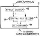
- FIG. 3shows a decoding unit 60 .
- FEC encoded datais received by the decoding unit 60 .
- a bit quality evaluator 62assigns a quality or correctness weighting to each input bit.
- the correctness-weighted datais processed by a detector 64 and a first decoder 66 .
- a second decoder 68decodes the output of the first decoder 66 , based on or according to error identification information received by the detector 64 .
- the second decoder 68outputs FEC decoded data output 28 , which is approximately equal to data input 10 ; the source data before being FEC encoded.
- a demodulatormay serve as the bit quality evaluator
- the first decoder 66may be a convolutional or Viterbi decoder
- the detector 64may perform error detection on a sliding window of M of N bits
- the second decoder 68may be a Reed Solomon decoder using erasure based on information provided by the detector 64 .
- FIG. 4shows a decoding process carried out by the decoding unit 60 .
- a portion of FEC encoded data 20 being evaluated by the bit quality evaluator 62is identified 80 to be prone to erroneous decoding by the first decoder 66 .
- the FEC-encoded datais decoded 82 by first decoder 66 .
- the output of the first decoder 66is further decoded 84 with the second decoder 68 , by taking into account a portion of encoded data 20 that has been identified as prone to be erroneously decoded.
- FIG. 5shows an embodiment of the process shown in FIG. 4 .
- the decoding unit 60receives 100 a signal with convolutional and Reed Solomon encoded data. A rank or level of correctness is assigned 102 to bits according to the quality of the signal. The quality rated bits are assessed 104 in the detector 64 . A portion of quality ranked data in the decoder 64 or sliding window is identified 106 as having a probability of being erroneously convolutionally decoded by the first decoder 66 . After or during the assessing 104 and the identifying 106 , the quality ranked bit data generated by the assigning 102 is convolutionally decoded 108 by the first decoder 66 .
- a portion of the data identified 106is convolutionally decoded 108 along with the other quality ranked data.
- the convolutionally decoded data generated by the convolutional decoding 108is block decoded 110 by applying erasure to the identified portion (or the convolutionally decoded portion corresponding to the same).
- FIG. 6shows an embodiment of a decoder of the present invention. Items 40 – 52 , and 56 are discussed above with reference to FIG. 2 . The relations and interactions between items 40 – 50 are essentially described above with reference to FIG. 2 .
- the correctness-rated output of the QPSK demodulator 44is received by both the input of the AGC 48 and the input of an M of N detector 130 .
- the M of N detector 130passes tagging information to a delay 132 , and a tagging unit 134 receives the delayed tagging information from the delay 132 .
- the delay 132enables the output of the Viterbi decoder 50 , delayed by such decoding, to catch up with and synchronize with the tagging information generated by the M of N detector 130 .
- This synchronizationenables the tagging unit 134 to tag symbols output by the Viterbi decoder 50 that correspond to bits determined by the M of N detector 130 to be in a group or burst of quality ranked bits that are likely to or have a probability of being incorrectly decoded by the Viterbi decoder 50 .
- a de-interleaver 52receives the delayed tagging information from the tagging unit 134 and the first decoded output from the Viterbi decoder 50 . Because Reed Solomon decoding with erasure is usually performed by erasing (ignoring) any symbol which contains a bit in error, the de-interleaver 52 marks for erasure any symbol to be input to the Reed Solomon decoder 136 which contains a bit output by the Viterbi output 50 and tagged by the tagging unit 134 .
- the Reed Solomon decoder 136receives the tagged and untagged symbols from the de-interleaver 52 and performs Reed Solomon decoding with erasure.
- Reed Solomon decodingis performed on codeword units that are made up of a fixed number of symbols. Some of the symbols in a codeword represent data, and other symbols in a codeword contain parity information that is used to correct errors in the data symbols.
- Reed Solomon decodersgenerally decide which codeword is the correct codeword based on the minimum of the distances between the received codeword and each of the set of possible matching codewords.
- the present inventioncan correct twice as many symbol errors as a concatenated decoder using Reed Solomon hard decision decoding (decoding without erasure).
- the M of N detector 130has been described with reference to a fixed-length sliding window, other configurations may also be used.
- the parameters of the M of N detector 130may be dynamically set based on conditions within the decoding unit 60 .
- the operations of the M of N detector 130may also be externally configurable or programmable.
- the delay 132 , the tagging unit 134 , and the de-interleaver 52may be arranged in various configurations, or may not be required depending on the other components of the decoding unit 60 . Any number of hardware or software arrangements may be used to enable Reed Solomon soft-decision decoding with erasure based on predictable patterns of Viterbi decoding errors.
- Viterbi decoding failure-predictionhas been described with reference to a ratio or concentration of low quality bits within a sliding window (M out of N)
- other tests or algorithmsmay be used to identify in advance patterns or sequences of error prone quality ranked bits that are to be decoded by a Viterbi decoder 50 .
- FIG. 7shows an embodiment of a process of the present invention.
- An analog signal carrying FEC decoded data that has been subject to burst and/or random noise during transmissionis received 150 .
- the signalis amplified 152 and converted 154 to a digital signal.
- the digital signalis demodulated 156 , using, for example, binary or quadrature phase shift keying, and is quantized into 3 bit units representing the correctness of a 1 or 0 data value.
- the quantized or correctness ranked digital datais channeled to two different parallel processing paths. In a first path, within a sliding window of the quality ranked bits, it is determined 160 whether bits in the window are prone to erroneous Viterbi decoding.
- This determinationmay be based on the size of the window (e.g., the number of bits in the window), and also on the number or concentration (M/N) of bits in the window at a given time that have a quality level below a given bit quality threshold.
- the bit stream, including the bits (or corresponding bits) detected or determined 160 to be prone to erroneous Viterbi decoding,are delayed 164 and tagged 166 .
- the quantized or quality ranked bitsare digitally filtered 158 and Viterbi decoded 162 using soft-decision decoding according to the correctness of individual data bits as indicated by the 3 bit units.
- the Viterbi soft-decision decoding 162consumes or does not output the quality ranking, and outputs hard (unranked) Viterbi decoded bits, which have no inherent quality or correctness value or rating.
- the bits output by the Viterbi decoding 162 that correspond to bits determined 160 to be prone to erroneous Viterbi decodingare tagged for erasure 168 .
- the Viterbi decoded 162 output, including the bits tagged for erasure 168are Reed Solomon soft-decision decoded 170 by erasing symbols that contain tagged bits. The result is outputted 172 . Accordingly, the second-decoded output of the Reed Solomon decoding 170 has been error corrected.
- FIG. 8shows a process by which operating parameters of the M of N detector 130 may be determined.
- the operating parameters of the detector 130may include, for example, the size of the sliding window (N), the number of low quality bits (M) which indicate a maximum portion of the window that is allowed to contain low-quality ranked bits before bits in that window (some or all) should be tagged for erasure, and a quality or correctness threshold level parameter which the M bits fall below.
- Nthe size of the sliding window
- Mthe number of low quality bits
- Mlow quality bits
- a quality or correctness threshold level parameterwhich the M bits fall below.
- the value of the selected parameteris modified 194 and the predicting 192 and modifying 194 is repeated until predicted bit error rates over a range of values of the parameter is completed 196 . This process is performed until various parameters affecting the BER have been tested 198 .
- the parameter values that resulted in an optimal predicted BERare selected 200 and used 202 for decoding.
- bit-quality groupingsmay be used (e.g. 4 medium quality bits, and 2 low-quality bits).
- Statistical distributionsmay be used. Patterns or arrangements may also be used to detect error-prone portions.
- FIG. 9shows bit quality thresholds 210 and 212 .
- the thresholds 210 and 212are used to determine the M number of low quality bits within a given window.
- the process for deriving prediction parameters(moving them along the axis), discussed above with reference to FIG. 8 , may be used to determine the voltage thresholds 210 and 212 .
- FIG. 10shows an example of bit error rate predictions based on different M, N, and low quality voltage threshold values.
Landscapes
- Physics & Mathematics (AREA)
- Probability & Statistics with Applications (AREA)
- Engineering & Computer Science (AREA)
- Theoretical Computer Science (AREA)
- Mathematical Physics (AREA)
- Algebra (AREA)
- General Physics & Mathematics (AREA)
- Pure & Applied Mathematics (AREA)
- Error Detection And Correction (AREA)
- Detection And Prevention Of Errors In Transmission (AREA)
Abstract
Description
Claims (12)
Priority Applications (8)
| Application Number | Priority Date | Filing Date | Title |
|---|---|---|---|
| US10/116,132US7093188B2 (en) | 2002-04-05 | 2002-04-05 | Decoding method and apparatus |
| PCT/US2003/010639WO2003088505A2 (en) | 2002-04-05 | 2003-04-07 | A decoding method and apparatus |
| AU2003228459AAU2003228459A1 (en) | 2002-04-05 | 2003-04-07 | A decoding method and apparatus |
| US11/472,423US20060242546A1 (en) | 2002-04-05 | 2006-06-22 | Decoding method and apparatus |
| US11/473,658US7549106B2 (en) | 2002-04-05 | 2006-06-23 | Decoding method |
| US11/761,671US8006170B2 (en) | 2002-04-05 | 2007-06-12 | Fault tolerant decoding method and apparatus including use of quality information |
| US11/761,662US8151175B2 (en) | 2002-04-05 | 2007-06-12 | Fault tolerant decoding method and apparatus |
| US12/484,401US8190964B2 (en) | 2002-04-05 | 2009-06-15 | Decoding method |
Applications Claiming Priority (1)
| Application Number | Priority Date | Filing Date | Title |
|---|---|---|---|
| US10/116,132US7093188B2 (en) | 2002-04-05 | 2002-04-05 | Decoding method and apparatus |
Related Child Applications (2)
| Application Number | Title | Priority Date | Filing Date |
|---|---|---|---|
| US11/472,423DivisionUS20060242546A1 (en) | 2002-04-05 | 2006-06-22 | Decoding method and apparatus |
| US11/473,658DivisionUS7549106B2 (en) | 2002-04-05 | 2006-06-23 | Decoding method |
Publications (2)
| Publication Number | Publication Date |
|---|---|
| US20030192001A1 US20030192001A1 (en) | 2003-10-09 |
| US7093188B2true US7093188B2 (en) | 2006-08-15 |
Family
ID=28673899
Family Applications (3)
| Application Number | Title | Priority Date | Filing Date |
|---|---|---|---|
| US10/116,132Expired - Fee RelatedUS7093188B2 (en) | 2002-04-05 | 2002-04-05 | Decoding method and apparatus |
| US11/472,423AbandonedUS20060242546A1 (en) | 2002-04-05 | 2006-06-22 | Decoding method and apparatus |
| US11/473,658Expired - LifetimeUS7549106B2 (en) | 2002-04-05 | 2006-06-23 | Decoding method |
Family Applications After (2)
| Application Number | Title | Priority Date | Filing Date |
|---|---|---|---|
| US11/472,423AbandonedUS20060242546A1 (en) | 2002-04-05 | 2006-06-22 | Decoding method and apparatus |
| US11/473,658Expired - LifetimeUS7549106B2 (en) | 2002-04-05 | 2006-06-23 | Decoding method |
Country Status (3)
| Country | Link |
|---|---|
| US (3) | US7093188B2 (en) |
| AU (1) | AU2003228459A1 (en) |
| WO (1) | WO2003088505A2 (en) |
Cited By (10)
| Publication number | Priority date | Publication date | Assignee | Title |
|---|---|---|---|---|
| US20050259765A1 (en)* | 2004-05-24 | 2005-11-24 | Stefan Keller | Apparatus and method for decoding a bit sequence from QPSK or QAM symbols |
| US20060107176A1 (en)* | 2004-11-04 | 2006-05-18 | Hongwei Song | Concatenated iterative and algebraic coding |
| US20070094561A1 (en)* | 2005-10-20 | 2007-04-26 | Jon Udell | Methods for distribution of test generation programs |
| US20070245208A1 (en)* | 2006-04-13 | 2007-10-18 | Nee Chi-Ping | Erasures assisted block code decoder and related method |
| US20080165905A1 (en)* | 2007-01-10 | 2008-07-10 | Bernd Heise | Monitoring and adjusting noise parameters |
| US20080216076A1 (en)* | 2005-10-20 | 2008-09-04 | Jon Udell | Methods for distributing programs for generating test data |
| US20120060071A1 (en)* | 2010-09-03 | 2012-03-08 | Snu R&Db Foundation | Product code decoding method and device |
| US8473826B1 (en)* | 2009-08-12 | 2013-06-25 | The United States Of America As Represented By The Secretary Of The Navy | Hybrid soft decision hard decision reed solomon decoding |
| US8583996B2 (en) | 2010-07-30 | 2013-11-12 | Michael Anthony Maiuzzo | Method and apparatus for determining bits in a convolutionally decoded output bit stream to be marked for erasure |
| US8745474B2 (en)* | 2010-07-30 | 2014-06-03 | Michael Anthony Maiuzzo | Method and apparatus for determining bits in a convolutionally decoded output bit stream to be marked for erasure |
Families Citing this family (15)
| Publication number | Priority date | Publication date | Assignee | Title |
|---|---|---|---|---|
| US7085282B2 (en)* | 2003-07-01 | 2006-08-01 | Thomson Licensing | Method and apparatus for providing forward error correction |
| US7228489B1 (en)* | 2003-12-26 | 2007-06-05 | Storage Technology Corporation | Soft viterbi Reed-Solomon decoder |
| GB2414638A (en)* | 2004-05-26 | 2005-11-30 | Tandberg Television Asa | Decoding a concatenated convolutional-encoded and block encoded signal |
| US8606081B2 (en)* | 2005-03-22 | 2013-12-10 | Panasonic Corporation | Stream data recording device, stream data recording/reproducing device, stream data reproduction device, stream data editing device, stream recording method, and stream reproducing method |
| US7890847B2 (en)* | 2007-03-09 | 2011-02-15 | Mediatek Inc. | Apparatus and method for calculating error metrics in a digital communication system |
| US7865812B2 (en)* | 2007-02-16 | 2011-01-04 | Mediatek Inc. | Apparatus and method for determining a detected punctured position in punctured convolutional codes |
| US7673222B2 (en)* | 2005-07-15 | 2010-03-02 | Mediatek Incorporation | Error-correcting apparatus including multiple error-correcting modules functioning in parallel and related method |
| US8286051B2 (en)* | 2005-07-15 | 2012-10-09 | Mediatek Inc. | Method and apparatus for burst error detection and digital communication device |
| US7603591B2 (en)* | 2005-07-19 | 2009-10-13 | Mediatek Incorporation | Apparatus selectively adopting different determining criteria in erasure marking procedure when performing decoding process, and method thereof |
| US7930617B1 (en)* | 2007-06-20 | 2011-04-19 | Rockwell Collins, Inc. | Sliding window block codes for cross-packet coding |
| US7752531B2 (en)* | 2007-09-12 | 2010-07-06 | Seagate Technology Llc | Defect sensing Viterbi based detector |
| KR101361598B1 (en)* | 2007-10-01 | 2014-02-12 | 에이저 시스템즈 엘엘시 | Systems and methods for media defect detection |
| FR2924877B1 (en)* | 2007-12-11 | 2011-04-01 | Thales Sa | METHOD AND MODULE FOR CORRECTING TRANSMISSION ERRORS IN A DATA STREAM, COMMUNICATION SYSTEM COMPRISING SAID MODULE |
| US10019223B2 (en) | 2015-09-03 | 2018-07-10 | Shure Acquisition Holdings, Inc. | Soft decision audio decoding system |
| US10644837B2 (en)* | 2018-08-01 | 2020-05-05 | Nxp B.V. | Signal processing with error correction |
Citations (8)
| Publication number | Priority date | Publication date | Assignee | Title |
|---|---|---|---|---|
| US5511081A (en)* | 1992-07-22 | 1996-04-23 | Deutsche Forschungsanstalt Fur Luft- Und Raumfahrt E.V. | Method for source-controlled channel decoding by expanding the Viterbi algorithm |
| US5825807A (en)* | 1995-11-06 | 1998-10-20 | Kumar; Derek D. | System and method for multiplexing a spread spectrum communication system |
| US6029264A (en)* | 1997-04-28 | 2000-02-22 | The Trustees Of Princeton University | System and method for error correcting a received data stream in a concatenated system |
| US6108811A (en) | 1996-10-18 | 2000-08-22 | Mitsubishi Denki Kabushiki Kaisha | Error-correcting decoder continuously adding flag signals to locations preceding a first location at which a difference between path metrics is lower than the threshold |
| WO2001048927A1 (en) | 1999-12-24 | 2001-07-05 | Ensemble Communications, Inc. | Method and apparatus for concatenated channel coding |
| US20010025358A1 (en) | 2000-01-28 | 2001-09-27 | Eidson Donald Brian | Iterative decoder employing multiple external code error checks to lower the error floor |
| EP1187340A2 (en) | 2000-08-30 | 2002-03-13 | Kabushiki Kaisha Toshiba | Error correction apparatus equipped with turbo decoder |
| US20020034269A1 (en) | 2000-07-28 | 2002-03-21 | Victor Demjanenko | Use of soft-decision or sum-product inner coders to improve the performance of outer coders |
Family Cites Families (16)
| Publication number | Priority date | Publication date | Assignee | Title |
|---|---|---|---|---|
| US5220568A (en)* | 1988-05-31 | 1993-06-15 | Eastman Kodak Company | Shift correcting code for channel encoded data |
| US5058115A (en)* | 1989-03-10 | 1991-10-15 | International Business Machines Corp. | Fault tolerant computer memory systems and components employing dual level error correction and detection with lock-up feature |
| US5602857A (en)* | 1993-09-21 | 1997-02-11 | Cirrus Logic, Inc. | Error correction method and apparatus |
| US5600663A (en)* | 1994-11-16 | 1997-02-04 | Lucent Technologies Inc. | Adaptive forward error correction system |
| US5689439A (en)* | 1995-03-31 | 1997-11-18 | Lucent Technologies, Inc. | Switched antenna diversity transmission method and system |
| US5631909A (en)* | 1995-05-31 | 1997-05-20 | Quantum Corporation | Method and apparatus for determining burst errors in an error pattern |
| US5835165A (en)* | 1995-06-07 | 1998-11-10 | Lsi Logic Corporation | Reduction of false locking code words in concatenated decoders |
| US5612956A (en)* | 1995-12-15 | 1997-03-18 | General Instrument Corporation Of Delaware | Reformatting of variable rate data for fixed rate communication |
| US5996103A (en)* | 1996-07-31 | 1999-11-30 | Samsung Information Systems America | Apparatus and method for correcting errors in a communication system |
| US5875199A (en)* | 1996-08-22 | 1999-02-23 | Lsi Logic Corporation | Video device with reed-solomon erasure decoder and method thereof |
| US5812603A (en)* | 1996-08-22 | 1998-09-22 | Lsi Logic Corporation | Digital receiver using a concatenated decoder with error and erasure correction |
| US5708665A (en)* | 1996-08-22 | 1998-01-13 | Lsi Logic Corporation | Digital receiver using equalization and block decoding with erasure and error correction |
| JPH113573A (en)* | 1997-04-15 | 1999-01-06 | Mitsubishi Electric Corp | Error correction decoding method and error correction decoding device for extended Reed-Solomon code, error correction method and error correction device for first-order expanded Reed-Solomon code, and error correction method and error correction device for second-order expansion Reed-Solomon code |
| US5870412A (en)* | 1997-12-12 | 1999-02-09 | 3Com Corporation | Forward error correction system for packet based real time media |
| JP3450756B2 (en)* | 1999-09-08 | 2003-09-29 | 松下電器産業株式会社 | Error correction method and error correction device |
| JP4323707B2 (en)* | 2000-10-25 | 2009-09-02 | 富士通マイクロエレクトロニクス株式会社 | Flash memory defect management method |
- 2002
- 2002-04-05USUS10/116,132patent/US7093188B2/ennot_activeExpired - Fee Related
- 2003
- 2003-04-07AUAU2003228459Apatent/AU2003228459A1/ennot_activeAbandoned
- 2003-04-07WOPCT/US2003/010639patent/WO2003088505A2/ennot_activeApplication Discontinuation
- 2006
- 2006-06-22USUS11/472,423patent/US20060242546A1/ennot_activeAbandoned
- 2006-06-23USUS11/473,658patent/US7549106B2/ennot_activeExpired - Lifetime
Patent Citations (8)
| Publication number | Priority date | Publication date | Assignee | Title |
|---|---|---|---|---|
| US5511081A (en)* | 1992-07-22 | 1996-04-23 | Deutsche Forschungsanstalt Fur Luft- Und Raumfahrt E.V. | Method for source-controlled channel decoding by expanding the Viterbi algorithm |
| US5825807A (en)* | 1995-11-06 | 1998-10-20 | Kumar; Derek D. | System and method for multiplexing a spread spectrum communication system |
| US6108811A (en) | 1996-10-18 | 2000-08-22 | Mitsubishi Denki Kabushiki Kaisha | Error-correcting decoder continuously adding flag signals to locations preceding a first location at which a difference between path metrics is lower than the threshold |
| US6029264A (en)* | 1997-04-28 | 2000-02-22 | The Trustees Of Princeton University | System and method for error correcting a received data stream in a concatenated system |
| WO2001048927A1 (en) | 1999-12-24 | 2001-07-05 | Ensemble Communications, Inc. | Method and apparatus for concatenated channel coding |
| US20010025358A1 (en) | 2000-01-28 | 2001-09-27 | Eidson Donald Brian | Iterative decoder employing multiple external code error checks to lower the error floor |
| US20020034269A1 (en) | 2000-07-28 | 2002-03-21 | Victor Demjanenko | Use of soft-decision or sum-product inner coders to improve the performance of outer coders |
| EP1187340A2 (en) | 2000-08-30 | 2002-03-13 | Kabushiki Kaisha Toshiba | Error correction apparatus equipped with turbo decoder |
Cited By (20)
| Publication number | Priority date | Publication date | Assignee | Title |
|---|---|---|---|---|
| US7680219B2 (en)* | 2004-05-24 | 2010-03-16 | Trident Microsystems (Far East) Ltd. | Apparatus and method for decoding a bit sequence from QPSK or QAM symbols |
| US20050259765A1 (en)* | 2004-05-24 | 2005-11-24 | Stefan Keller | Apparatus and method for decoding a bit sequence from QPSK or QAM symbols |
| US20060107176A1 (en)* | 2004-11-04 | 2006-05-18 | Hongwei Song | Concatenated iterative and algebraic coding |
| US7516389B2 (en)* | 2004-11-04 | 2009-04-07 | Agere Systems Inc. | Concatenated iterative and algebraic coding |
| US20070094561A1 (en)* | 2005-10-20 | 2007-04-26 | Jon Udell | Methods for distribution of test generation programs |
| US7765450B2 (en) | 2005-10-20 | 2010-07-27 | Jon Udell | Methods for distribution of test generation programs |
| US20080216076A1 (en)* | 2005-10-20 | 2008-09-04 | Jon Udell | Methods for distributing programs for generating test data |
| US20080320352A1 (en)* | 2005-10-20 | 2008-12-25 | Mentor Graphics Corporation | Methods for distribution of test generation programs |
| US7669101B2 (en)* | 2005-10-20 | 2010-02-23 | Jon Udell | Methods for distributing programs for generating test data |
| US7734984B2 (en)* | 2006-04-13 | 2010-06-08 | Trident Microsystems (Far East) Ltd. | Erasures assisted block code decoder and related method |
| US20070245208A1 (en)* | 2006-04-13 | 2007-10-18 | Nee Chi-Ping | Erasures assisted block code decoder and related method |
| US20100229070A1 (en)* | 2006-04-13 | 2010-09-09 | Nee Chi-Ping | Erasures Assisted Block Code Decoder And Related Method |
| US8065593B2 (en) | 2006-04-13 | 2011-11-22 | Trident Microsystems (Far East) Ltd. | Erasures assisted block code decoder and related method |
| US20080165905A1 (en)* | 2007-01-10 | 2008-07-10 | Bernd Heise | Monitoring and adjusting noise parameters |
| US8027379B2 (en)* | 2007-01-10 | 2011-09-27 | Lantiq Deutschland Gmbh | Monitoring and adjusting noise parameters |
| US8473826B1 (en)* | 2009-08-12 | 2013-06-25 | The United States Of America As Represented By The Secretary Of The Navy | Hybrid soft decision hard decision reed solomon decoding |
| US8583996B2 (en) | 2010-07-30 | 2013-11-12 | Michael Anthony Maiuzzo | Method and apparatus for determining bits in a convolutionally decoded output bit stream to be marked for erasure |
| US8745474B2 (en)* | 2010-07-30 | 2014-06-03 | Michael Anthony Maiuzzo | Method and apparatus for determining bits in a convolutionally decoded output bit stream to be marked for erasure |
| US20120060071A1 (en)* | 2010-09-03 | 2012-03-08 | Snu R&Db Foundation | Product code decoding method and device |
| US8468430B2 (en)* | 2010-09-03 | 2013-06-18 | Snu R&Db Foundation | Product code decoding method and device |
Also Published As
| Publication number | Publication date |
|---|---|
| US20030192001A1 (en) | 2003-10-09 |
| WO2003088505A2 (en) | 2003-10-23 |
| US20060242547A1 (en) | 2006-10-26 |
| WO2003088505A8 (en) | 2003-12-18 |
| US7549106B2 (en) | 2009-06-16 |
| WO2003088505A3 (en) | 2004-03-18 |
| US20060242546A1 (en) | 2006-10-26 |
| AU2003228459A1 (en) | 2003-10-27 |
Similar Documents
| Publication | Publication Date | Title |
|---|---|---|
| US7549106B2 (en) | Decoding method | |
| US8190964B2 (en) | Decoding method | |
| US7577899B2 (en) | Cyclic redundancy check (CRC) based error correction method and device | |
| US8074151B1 (en) | Correcting errors in disk drive read back signals by iterating with the reed-solomon decoder | |
| CA2710773C (en) | Decoding scheme using multiple hypotheses about transmitted messages | |
| US8127216B2 (en) | Reduced state soft output processing | |
| US8671335B2 (en) | Soft output Viterbi detector with error event output | |
| US7480852B2 (en) | Method and system for improving decoding efficiency in wireless receivers | |
| US20090319844A1 (en) | Apparatus selectively adopting different determining criteria in erasure marking procedure when performing decoding process, and method thereof | |
| US8006170B2 (en) | Fault tolerant decoding method and apparatus including use of quality information | |
| US20070153693A1 (en) | Transport format detecting apparatus and method | |
| US8151175B2 (en) | Fault tolerant decoding method and apparatus | |
| US7861137B2 (en) | System for identifying localized burst errors | |
| US8745474B2 (en) | Method and apparatus for determining bits in a convolutionally decoded output bit stream to be marked for erasure | |
| US7043678B2 (en) | Method for identifying bad frames | |
| US8583996B2 (en) | Method and apparatus for determining bits in a convolutionally decoded output bit stream to be marked for erasure | |
| US7386779B2 (en) | Systems and methods for correcting errors in a received frame | |
| US20100011279A1 (en) | Error correcting viterbi decoder | |
| US20070033495A1 (en) | Code-word list algorithm | |
| CN110460339B (en) | Method and device for detecting convolutional code decoding, storage medium and electronic equipment | |
| Freudenberger et al. | An algorithm for detecting unreliable code sequence segments and its applications | |
| JPH05235906A (en) | Decoder fro multi-dimension code and error correction/ detection system using decoder | |
| JP2022153920A (en) | Interference wave determination device, interference wave determination method, interference wave determination program, and receiver | |
| JP4918059B2 (en) | Receiving apparatus and Viterbi decoding method | |
| GB2411326A (en) | Viterbi decoder with single wrong turn correction using path discriminant values |
Legal Events
| Date | Code | Title | Description |
|---|---|---|---|
| AS | Assignment | Owner name:ALION SCIENCE AND TECHNOLOGY CORP., VIRGINIA Free format text:ASSIGNMENT OF ASSIGNORS INTEREST;ASSIGNOR:ILLINOIS INSTITUTE OF TECHNOLOGY RESEARCH INSTITUTE;REEL/FRAME:013828/0254 Effective date:20020704 Owner name:ALION SCIENCE AND TECHNOLOGY CORP.,VIRGINIA Free format text:ASSIGNMENT OF ASSIGNORS INTEREST;ASSIGNOR:ILLINOIS INSTITUTE OF TECHNOLOGY RESEARCH INSTITUTE;REEL/FRAME:013828/0254 Effective date:20020704 | |
| AS | Assignment | Owner name:ALION SCIENCE AND TECHNOLOGY CORP., VIRGINIA Free format text:ASSIGNMENT OF ASSIGNORS INTEREST;ASSIGNOR:ILLINOIS INSTITUTE OF TECHNOLOGY RESEARCH INSTITUTE;REEL/FRAME:014523/0245 Effective date:20020704 Owner name:ALION SCIENCE AND TECHNOLOGY CORP.,VIRGINIA Free format text:ASSIGNMENT OF ASSIGNORS INTEREST;ASSIGNOR:ILLINOIS INSTITUTE OF TECHNOLOGY RESEARCH INSTITUTE;REEL/FRAME:014523/0245 Effective date:20020704 | |
| AS | Assignment | Owner name:CREDIT SUISSE FIRST BOSTON, AS COLLATERAL AGENT, N Free format text:SECURITY INTEREST;ASSIGNOR:ALION SCIENCE AND TECHNOLOGY CORPORATION;REEL/FRAME:015829/0437 Effective date:20040802 Owner name:CREDIT SUISSE FIRST BOSTON, AS COLLATERAL AGENT,NE Free format text:SECURITY INTEREST;ASSIGNOR:ALION SCIENCE AND TECHNOLOGY CORPORATION;REEL/FRAME:015829/0437 Effective date:20040802 | |
| AS | Assignment | Owner name:SENTEL CORPORATION, VIRGINIA Free format text:ASSIGNMENT OF ASSIGNORS INTEREST;ASSIGNOR:MAIUZZO, MICHAEL A.;REEL/FRAME:016913/0501 Effective date:20040315 | |
| CC | Certificate of correction | ||
| AS | Assignment | Owner name:ALION SCIENCE AND TECHNOLOGY CORPORATION, VIRGINIA Free format text:ASSIGNMENT OF ASSIGNORS INTEREST;ASSIGNOR:ROBERTS, KENNETH KAHLE;REEL/FRAME:020753/0178 Effective date:20080315 Owner name:ALION SCIENCE AND TECHNOLOGY CORPORATION, VIRGINIA Free format text:JOINT EXPLOITATION AGREEMENT;ASSIGNORS:ALION SCIENCE AND TECHNOLOGY CORPORATION;SENTEL CORPORATION;REEL/FRAME:020783/0637;SIGNING DATES FROM 20040317 TO 20040427 Owner name:SENTEL CORPORATION, VIRGINIA Free format text:JOINT EXPLOITATION AGREEMENT;ASSIGNORS:ALION SCIENCE AND TECHNOLOGY CORPORATION;SENTEL CORPORATION;REEL/FRAME:020783/0637;SIGNING DATES FROM 20040317 TO 20040427 | |
| REMI | Maintenance fee reminder mailed | ||
| AS | Assignment | Owner name:ALION SCIENCE AND TECHNOLOGY CORPORATION,VIRGINIA Free format text:RELEASE OF SECURITY INTERESTS;ASSIGNOR:CREDIT SUISSE AG, CAYMAN ISLANDS BRANCH (FORMERLY KNOWN AS CREDIT SUISSE FIRST BOSTON);REEL/FRAME:024244/0982 Effective date:20100322 Owner name:ALION-BMH CORPORATION (FORMERLY KNOWN AS BMH ASSOC Free format text:RELEASE OF SECURITY INTERESTS;ASSIGNOR:CREDIT SUISSE AG, CAYMAN ISLANDS BRANCH (FORMERLY KNOWN AS CREDIT SUISSE FIRST BOSTON);REEL/FRAME:024244/0982 Effective date:20100322 Owner name:ALION-MA&D CORPORATION,VIRGINIA Free format text:RELEASE OF SECURITY INTERESTS;ASSIGNOR:CREDIT SUISSE AG, CAYMAN ISLANDS BRANCH (FORMERLY KNOWN AS CREDIT SUISSE FIRST BOSTON);REEL/FRAME:024244/0982 Effective date:20100322 | |
| AS | Assignment | Owner name:WILMINGTON TRUST COMPANY, AS COLLATERAL AGENT,DELA Free format text:SECURITY AGREEMENT;ASSIGNOR:ALION SCIENCE AND TECHNOLOGY CORPORATION;REEL/FRAME:024252/0327 Effective date:20100322 Owner name:WILMINGTON TRUST COMPANY, AS COLLATERAL AGENT, DEL Free format text:SECURITY AGREEMENT;ASSIGNOR:ALION SCIENCE AND TECHNOLOGY CORPORATION;REEL/FRAME:024252/0327 Effective date:20100322 | |
| LAPS | Lapse for failure to pay maintenance fees | ||
| STCH | Information on status: patent discontinuation | Free format text:PATENT EXPIRED DUE TO NONPAYMENT OF MAINTENANCE FEES UNDER 37 CFR 1.362 | |
| FP | Lapsed due to failure to pay maintenance fee | Effective date:20100815 | |
| AS | Assignment | Owner name:WILMINGTON TRUST COMPANY, AS COLLATERAL AGENT, DEL Free format text:SECURITY INTEREST;ASSIGNOR:ALION SCIENCE AND TECHNOLOGY CORPORATION;REEL/FRAME:032836/0300 Effective date:20140502 | |
| AS | Assignment | Owner name:ALION SCIENCE AND TECHNOLOGY CORPORATION, VIRGINIA Free format text:RELEASE OF SECURITY INTEREST;ASSIGNOR:WILMINGTON TRUST COMPANY, AS COLLATERAL AGENT;REEL/FRAME:033647/0327 Effective date:20140818 |