US7092554B2 - Method for detecting eye and mouth positions in a digital image - Google Patents
Method for detecting eye and mouth positions in a digital imageDownload PDFInfo
- Publication number
- US7092554B2 US7092554B2US09/846,718US84671801AUS7092554B2US 7092554 B2US7092554 B2US 7092554B2US 84671801 AUS84671801 AUS 84671801AUS 7092554 B2US7092554 B2US 7092554B2
- Authority
- US
- United States
- Prior art keywords
- iris
- eye
- pixel
- mouth
- image
- Prior art date
- Legal status (The legal status is an assumption and is not a legal conclusion. Google has not performed a legal analysis and makes no representation as to the accuracy of the status listed.)
- Expired - Fee Related, expires
Links
Images


Classifications
- G—PHYSICS
- G06—COMPUTING OR CALCULATING; COUNTING
- G06T—IMAGE DATA PROCESSING OR GENERATION, IN GENERAL
- G06T7/00—Image analysis
- G06T7/70—Determining position or orientation of objects or cameras
- G06T7/73—Determining position or orientation of objects or cameras using feature-based methods
- G06T7/74—Determining position or orientation of objects or cameras using feature-based methods involving reference images or patches
- G—PHYSICS
- G06—COMPUTING OR CALCULATING; COUNTING
- G06V—IMAGE OR VIDEO RECOGNITION OR UNDERSTANDING
- G06V40/00—Recognition of biometric, human-related or animal-related patterns in image or video data
- G06V40/10—Human or animal bodies, e.g. vehicle occupants or pedestrians; Body parts, e.g. hands
- G06V40/16—Human faces, e.g. facial parts, sketches or expressions
- G06V40/168—Feature extraction; Face representation
- G—PHYSICS
- G06—COMPUTING OR CALCULATING; COUNTING
- G06V—IMAGE OR VIDEO RECOGNITION OR UNDERSTANDING
- G06V40/00—Recognition of biometric, human-related or animal-related patterns in image or video data
- G06V40/10—Human or animal bodies, e.g. vehicle occupants or pedestrians; Body parts, e.g. hands
- G06V40/18—Eye characteristics, e.g. of the iris
Definitions
- the present inventionrelates to digital image processing methods, and more particularly to methods of detecting human eye and mouth positions.
- eye-mouth coordinationIn digital image processing it is often useful to find the eye-mouth coordination, that is, to detect/locate an eye and mouth position. This information can be used, for example, to find the pose of a human face in the image. Since human faces may often be distinguished by their features, eye-mouth coordination also can be used as a pre-processor for applications such as face recognition that is further used in image retrieval.
- U.S. Pat. No. 6,072,892which issued Jun. 6, 2000 discloses an eye position detecting apparatus and method.
- the disclosed method for detecting the position of eyes in a facial imageuses a thresholding method on an intensity histogram of the image to find three peaks in the histogram representing skin, white of the eye, and pupil.
- An object of the present inventionis to provide a digital image processing method for locating eyes and mouth in a digital face image.
- Still another object of the present inventionis to provide such a method which is effective for automatically obtaining eye and mouth positions in a frontal face image.
- Yet another object of the present inventionis to provide such a method which reduces the region of the image that must be searched.
- Another object of the present inventionis to provide such a method which reduces the computation required to locate the eye and mouth.
- a still further object of the present inventionis to provide such a method which reduces the incidence of false positives.
- a digital image processing methodfor locating eyes and mouth in a digital face image.
- the methodincludes the steps of detecting iris colored pixels in the digital face image; grouping the iris colored pixels into clusters; detecting eye positions using the iris colored pixels; identifying salient pixels relating to a facial feature in the digital face image; generating a signature curve using the salient pixels; and using the signature curve and the eye positions to locate a mouth position.
- a summation of squared difference methodis used to detect the eye positions.
- the eyes and mouth positionsare validated using statistics.
- the present inventionprovides a method which is effective for automatically obtaining eye and mouth positions in a frontal face image.
- the methodreduces the region of the image that must be searched, thereby reducing the computation required to locate eye and mouth, and reducing the incidence of false positives.
- FIG. 1shows a schematic diagram of an image processing system suitable for use with a method in accordance with the present invention
- FIG. 2shows a flow diagram illustrating the method of determining eye-mouth coordination in accordance with the present invention
- FIG. 3is an illustration showing parameters of a human face region
- FIG. 4( a )shows a plot representing iris and noniris pixel intensity distributions
- FIG. 4( b )shows a flow diagram illustrating the process of Bayesian iris modeling
- FIG. 5shows a flow diagram showing eye position estimation steps
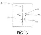
- FIG. 6is an illustration showing iris color pixel clusters
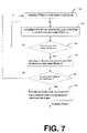
- FIG. 7shows a flow diagram illustrating the summation of squared difference used in eye template matching
- FIG. 8is a view of an eye template in searching eye patches in an image
- FIG. 9( a )shows a flow diagram for finding mouth position
- FIG. 9( b )shows a kernel
- FIG. 9( c )is a view of facial salient pixels and their projection onto the vertical axis
- FIG. 9( d )is an illustration of a lower half and upper half of a face region
- FIG. 9( e )shows a plot representative of a signature curve and peak points
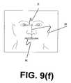
- FIG. 9( f )shows an illustration of parameters M, E, and D.
- FIG. 1shows an image processing system 50 suitable for use with a method in accordance with the present invention.
- System 50includes a digital image source 100 adapted to provide a color digital still image.
- digital image source 100include a scanner or other device for capturing images and converting the image for storage in digital form, a digital image capture device such as a digital camera, and a digital image storage device such as a memory card or compact disk drive with a CD.
- the digital imageis a facial image, preferably a frontal view, though the image may be angled from a frontal view.
- the digital image from digital image source 100is provided to an image processor 102 , such as a programmable personal computer, or digital image processing work station such as a Sun Sparc workstation.
- Image processor 102processes the digital image in accordance with the method of the present invention.
- image processor 102may be networked/connected to a CRT display or image display 104 , an interface device or other data/command entry device such as a keyboard 106 , and a data/command control device such as a mouse 108 .
- Image processor 102may also be networked/connected to a computer readable storage medium 107 .
- Image processor 102transmits the processed digital images to an output device 109 .
- Output device 109can comprise a printer, a long-term image storage device, a connection to another processor, or an image telecommunication device connected, for example, to the Internet.
- a printerin accordance with the present invention, can be a silver halide printer, thermal printer, ink jet printer, electrophotographic printer, and the like.
- the present inventioncomprises a computer program for detecting human eyes and mouths in a digital image in accordance with the method described.
- the computer program of the present inventioncan be utilized by any computer system known to those skilled in the art, such as the personal computer system of the type shown in FIG. 1 . Accordingly, many other types of computer systems can be used to execute the computer program of the present invention.
- the computer program of the present inventionmay employ image manipulation algorithms and processes that are known to those skilled in the art.
- the computer program embodiment of the present inventionmay embody conventional algorithms and processes not specifically shown or described herein that are useful for implementation.
- the computer program for performing the method of the present inventionmay be stored in computer readable storage medium 107 .
- Medium 107may comprise, for example, a magnetic storage media such as a magnetic disk (e.g., a hard drive or a floppy disk) or magnetic tape; an optical storage media such as an optical disc, optical tape, or machine readable bar code; a solid state electronic storage device such as random access memory (RAM), or read only memory (ROM); or any other physical device or medium employed to store a computer program.
- the computer program for performing the method of the present inventionmay also be stored on computer readable storage medium 107 connected to image processor 102 by means of the internet or other communication medium. Those skilled in the art will readily recognize that the equivalent of such a computer program may also be constructed in hardware.
- FIG. 2is a flow diagram illustrating a first embodiment of the method in accordance with the present invention of determining eye-mouth coordination.
- eye-mouth coordinate determinationcomprises several steps.
- a first step (step 200 )comprises detecting skin color regions (i.e., face regions) in the digital image.
- a second step (step 206 )comprises identifying iris color pixels from the face regions.
- a third step (step 208 )comprises estimating eye positions from the detected iris color pixels of second step 206 .
- a fourth step (step 212 )comprises identifying/extracting salient pixels in the face region and forming a signature curve with the salient pixels.
- a fifth step (step 214 )comprises estimating a mouth position based on the information gathered in third step 208 and fourth step 212 .
- a modeling step (step 216 )comprises forming an iris color Bayesian model training wherein second step 206 is provided with a look-up table for detecting iris color pixels.
- Modeling step (step 216 )is more particularly described below with regard to FIGS. 4( a ) and 4 ( b ). Further, modeling step 216 is performed once, preferably off-line.
- First step 200 in skin color region detectioncomprises three steps as illustrated in FIG. 2 , specifically, steps 201 , 202 , and 203 .
- step 201is a color histogram equalization step.
- Color histogram equalization step 201receives images to be processed and ensures that the images are in a form that will permit skin color detection.
- Step 201is employed since human skin may take on any number of colors in an image because of lighting conditions, flash settings or other circumstances. As such, it generally difficult to automatically detect skin in such images.
- color histogram equalization step 201a statistical analysis of each image is performed.
- the color histogram equalization of the digital face imageis preferably performed based on a mean intensity analysis of the digital face image.
- the imageis searched for skin color regions in skin color detection step 202 .
- a preferred method for detecting skin in a digital imageis the method that is described in commonly assigned U.S. Ser. No. 09/692,930, which issued as U.S. Pat. No. 6,690,822, incorporated herein by reference.
- skin color pixelsare separated from other pixels by defining a working color space that contains a range of possible skin colors collected from a large, well-balanced population of images. A pixel is then identified as a skin color pixel if the pixel has a color that is within the working color space.
- Skin color detection step 202identifies a region of skin color pixels in the image. This region can be defined in any number of ways. In one embodiment, the skin color region is defined by generating a set of pixel locations identifying the pixels in the image having skin colors. In another embodiment, a modified image is generated that contains only skin color pixels. In yet another embodiment, skin color detection step 202 defines boundaries that confine the skin color region in the image. It will be recognized by those skilled in the art that more than one skin color region can be identified in the image.
- Face region extraction step 203examines the skin color regions detected by skin color detection step 202 to locate skin color regions that may be indicative of a face. Face region extraction step 203 defines parameters that describe the size of the face and the location of the face within the image.
- FIG. 3more particularly illustrates the relationship between geometric parameters used to define a face region in the image.
- geometric parametersmay include a Face_top 300 , Face_bottom 302 , Face_left 304 , Face_right 306 , Face_center_row 308 , and Face_center_column 310 . These parameters can be used in subsequent processing of the image.
- second step 206examines the pixels in the face region to detect iris color pixels.
- second step 206determines whether a pixel is an iris by measuring the red intensity of the pixel. Red intensity levels are measured since it has been observed that that a human iris has a low red intensity level as compared to human skin which has a relatively high red intensity level.
- the method in accordance with the present inventiondoes not use a red level thresholding method to determine whether a pixel is to be classified as an iris or as a non-iris.
- the method of the present inventionclassifies a pixel as an iris or a non-iris pixel on the basis of a probability analysis.
- This probability analysisapplies an iris statistical model.
- the iris statistical modeldefines the probability that a pixel is an iris pixel based on the given red intensity level of the pixel.
- two conditional probability density distribution functionsare needed.
- FIG. 4( a )shows the two conditional probability density distribution functions.
- iris) 412represents the likelihood that a given iris pixel has a specific red intensity. For example, the likelihood that a given iris pixel has a red intensity level of 30 is 0.5, the same pixel has a red intensity level 255 is 0.0001.
- noniris) 414represents the likelihood that a given noniris pixel has a specific red intensity. For example, the likelihood that a given noniris pixel has a red intensity level of 30 is 0.0001, the same pixel has a red intensity level 255 is 0.1. The maximum value of a likelihood is one (e.g., 1).
- the probability analysiscan take many forms.
- the probabilitiescan be combined in various ways with a pixel being classified as an iris or not on the basis of the relationship between these probabilities.
- a mathematical construct known as a Bayes modelis employed to combine the probabilities to produce the posterior probability that a pixel having a given red intensity belongs to an iris.
- the Bayes modelis applied as follows:
- I)is a conditional probability that a given pixel intensity belongs to an iris
- iris)is a conditional probability that a given iris pixel has a specific intensity I (i.e., iris intensity distribution function 412 )
- P(iris)is a probability of the occurrence of an iris in the face region
- noniris)is a conditional probability that a given non-iris pixel has a specific intensity I (i.e., noniris intensity distribution function 414 )
- P(noniris)is a probability of the occurrence of a non-iris pixel in the face oval region.
- a pixelis classified as an iris if the conditional probability P(iris
- iris pixelscan be detected from a skin color region in an image without first detecting face boundaries or other shaped area.
- each pixel of the skin color regionis examined to detect iris color pixels and parameters defining the skin colored region are used later in the eye detection process.
- FIG. 4( b )shows a flow diagram illustrating the processes used in modeling step 216 , that is, iris color Bayesian model training of FIG. 2 , for developing the statistical models used to classify the pixels.
- Modeling step 216is performed before the method for detecting irises is used to detect iris pixels.
- FIG. 4( b )a large sample of frontal face images are collected and examined. All iris pixels and non-iris pixels in the face region of each image are then manually identified (steps 402 and 404 ).
- iris),is computed and the probability of the occurrence of an iris in the face oval region, P(iris), is computed (step 406 ); then the conditional probability that a given noniris pixel has a specific red intensity I, P(I
- the computed statistical models of iris and non-irisare used in the Bayes formula to produce the conditional probability that a pixel with a given intensity belongs to an iris, P(iris
- the Bayes modelcan be used to generate a look-up table to be used in second step 206 for iris color pixel detection.
- Second step 206the iris color pixel detection step, identifies the location of the iris color pixels in the image.
- the result from second step 206is an iris color pixel image in which noniris color pixels are set as zeros.
- the iris color pixel image resulting from second step 206is used in third step 208 .
- Third step 208is now more particularly described with regard to FIGS. 5 and 6 .
- FIG. 5shows a flow diagram illustrating third step 208 , the process of eye position detection using the iris color pixels.
- the eye position detection processstarts with an iris color pixel clustering step 500 . If iris color pixels are detected, then the iris pixels are assigned to a cluster.
- a clusteris a non-empty set of iris color pixels with the property that any pixel within the cluster is also within a predefined distance to another pixel in the cluster.
- a predefined distanceis one thirtieth of the digital image height.
- Iris color pixel clustering step 500 of FIG. 5groups iris color pixels into clusters based upon this definition of a cluster. However, it will be understood that pixels may be clustered on the basis of other criteria.
- a cluster of pixelsmay not be valid. Accordingly, an optional step of validating the clusters is shown in FIG. 5 as iris color pixel cluster validation step 501 .
- a clustermay be invalid, for example, if it contains too many iris color pixels or because the geometric relationship of the pixels in the cluster suggests that the cluster is not indicative of an iris. For example, if the ratio is greater than a pre-determined value, for example two, then the cluster is invalid. That is, the height to width ratio of each iris pixel cluster is determined, and the iris pixel cluster is invalid if the height to width ratio is greater than the predetermined value.
- a size measuremight also be considered.
- a size of each iris pixel clustercan be determined by counting the number of iris colored pixels within each iris pixel cluster; and the iris pixel cluster is invalid if the size of the size of the iris pixel cluster is greater than a pre-determined value. Invalid iris color pixel clusters are removed from further consideration by the method of the present invention. Accordingly, for ease of discussion, in the portions of the description that follow, valid iris color pixel clusters will hereinafter be referred to as iris pixel clusters.
- a center for each of the clustersis calculated in cluster centering step 502 .
- the center of a clusteris determined as the center of mass of the cluster.
- the center position of the clustersis calculated with respect to the origin of the image coordinate system.
- the origin of the image coordinate system for a digital imageis typically defined at the upper left corner of the image boundary.
- a face division step 504employs Face_center_column 310 to separate the skin color region into a left-half region and a right-half region.
- Face_center_column 310employs Face_center_column 310 to separate the skin color region into a left-half region and a right-half region.
- iris color pixel cluster 602 and cluster center 600 of the iris pixel clustersare positioned in either a left-half region 604 or a right-half region 606 separated by Face_center_column 310 .
- a left-eye position search step 506is conducted in left-half region 604 , preferably using a method known as the Summation of the Squared Difference.
- a right-eye position search step 508is conducted in right-half region 606 , preferably based on the same Summation of the Squared Difference method.
- the summation of the squared difference methodinvolves calculating the summation of the squared difference of the intensity values of the corresponding pixels in an eye template and a patch of the image that has the same size as the template.
- each pixel in the patch of pixelshas a corresponding pixel in the template.
- the difference between the intensity level of each of the corresponding pixelsis calculated.
- Each differenceis then squared.
- the sum of each of the squared differences for each of the pixels in the setis then calculated.
- This summation of the squared differencesprovides a relative measure of the degree of correspondence between each of the pixel sets measured and the template.
- the eye templateitself is generated by averaging a large number of sample eye images.
- a window 800is centered at each cluster center 600 in a respective half-region of the image ( 604 , 606 ).
- Window 800has a size which covers substantially the entire cluster about which it centers.
- An eye template 806is a template of an average eye, and moves within window 800 .
- summation of the squared difference valuesare calculated for each pixel in each window in each half region. These values are compared and the pixel having the lowest relative summation of the squared difference value is identified as an eye location for the half-region. This process is performed separately on the clusters of the left and the right-half regions of the image in the manner described below.
- the present inventionhas been described as using the summation of the squared difference method to identify the best relative match between the average eye template and each of the pixels, other methods to determine the degree of relative correspondence can be used.
- the mean-squared error methodcan be used in place of the summation of the squared difference method.
- left and right eye position search steps 506 and 508are started with centering window 800 at each cluster center 810 in a respective half region (step 700 ).
- the operation of calculating the summation of the squared differences (step 702 )is then performed, separately, using a patch of pixels centered on each of the pixels in each window 800 (step 704 ).
- the position of the pixel having the lowest summation of squared difference value in each window 800is recorded (step 706 ).
- the position of the pixel having the lowest summation of squared difference value for the half regionis recorded (step 709 ). This position is the eye position for the half-region.
- each iris pixel clusteris associated with either the right half region or the left half region.
- Eye template 806is defined, and window 800 is centered at the center of each iris pixel cluster.
- An image patchis defined as having a size substantially (preferably, exactly) equal to the size of the eye template. Then, to locate the right eye position in the right half region, the pixel intensity level difference is determined between the eye template and the image patch, with the image patch being centered at each pixel in each window, and the window being centered at each cluster in the right half region. Similarly, to locate the left eye position in the left half region, the pixel intensity level difference is determined between the eye template and the image patch, with the image patch being centered at each pixel in each window, and the window being centered at each cluster in the left half region.
- the summation of the squared difference method of steps 506 and 508 of FIG. 5can also be performed without the use of face region extraction.
- the skin colored regioncan be divided into a left-half region and a right-half region.
- Iris color pixel clusterscan then be divided into left-half region and right-half region clusters.
- the summation of the squared difference methodcan then be applied.
- Fourth step 212 and fifth step 214are used in finding a mouth position, and are more particularly described in FIGS. 9( a )– 9 ( f ).
- the input image to the step of extracting salient pixels and forming a signature curve (fourth step 212 )is the original color face image.
- a morphological opening operation(step 901 ) is first applied to the image to eliminate bright spots such as reflection of eye glasses or spectacles.
- the opening operationpreserves dark facial features such as eyes, nose and mouth.
- the input imageis then processed in step 902 with a high boost filter that is a type of high pass filter.
- the high boost filtering processis accomplished by convoluting the image with a high boost filter kernel 950 as shown in FIG. 9( b ).
- High boost filter kernel 950comprises a parameter H to be selected by the user.
- the action of a high pass filteris to remove flat intensity regions and retain places with high activities (i.e., intensity contrasts, between a dark region and a bright region). Examples of high activity places are shown as salient pixels 954 in FIG. 9( c ).
- Salient pixels 954are the result of thresholding the high boosted image into a binary image. Accordingly, step 904 comprises thresholding the high boosted image into a binary image to generate a binary image with salient pixels.
- An example of a binary image obtained after thresholding the high boost filtered original imageis shown in FIG. 9 ( c ) as 960 . Non-salient pixels are set to zeros.
- the example value of the parameter, H, of high boost filter kernel 950is chosen as 9 .
- step 906comprising projecting salient pixels 954 onto a vertical axis to obtain a signature curve 956 , as illustrated in FIG. 9( c ).
- the projectionis accomplished by counting the number of salient pixels 954 in the horizontal direction and then assigning the number to corresponding position on the vertical axis. It is evidently that there are more salient pixels in the eye and mouth regions than in any other regions. Therefore, the result of projecting salient pixels 954 is signature curve 956 with peaks signifying the places of mouth and eye regions.
- the search of mouth position in the vertical directionbecomes a search of a peak position on signature curve 956 .
- This searchis performed in step 908 .
- binary image 960is divided into an upper half region 962 and a lower half region 964 as shown in FIG. 9( d ).
- the divideris Face_center_row 308 obtained in face region extraction step 203 .
- the search of step 908is then performed in lower half region 964 of binary image 960 where the mouth resides.
- the section of signature curve 956 in lower half region 964may need to be smoothed a few times to remove spurs before the search takes place.
- FIG. 9( e )shows a smoothed signature curve 966 with a plurality of peak points 968 .
- the smoothing operation of signature curve 956 to generate smoothed signature curve 966can be performed, for example, using a moving average filter or a median filter.
- a peak being at position iis true if the following is satisfied: S ( i ⁇ 1) ⁇ S ( i ) ⁇ S ( i +1) where S(x) is the value of smoothed signature curve 966 at a position x.
- S(x)is the value of smoothed signature curve 966 at a position x.
- S(x)is the value of smoothed signature curve 966 at a position x.
- S(x)is the value of smoothed signature curve 966 at a position x.
- the position of the highest peak valueis recorded.
- the reason for recording the highest peak valueis because the mouth region most likely has more salient pixels 954 than other facial features such as a nose.
- the recorded peak positionis subsequently used as the mouth position in
- the position of the mouth in the horizontal directionis determined at step 910 wherein the middle position is found between the two eyes detected in third step 208 .
- This positionis also used in step 912 wherein the eye-mouth coordination is validated.
- the identified horizontal and vertical positions of the mouthare used as a starting point to group salient pixels 954 in the neighborhood of the identified mouth position into a mouth salient pixel cluster. That is, the salient pixels generally surrounding the identified mouth position are grouped into a mouth salient pixel cluster.
- a distance M between a left and right boundary of the mouth salient pixel clusteris determined.
- a distance E between the two eyes positions identified in third step 208is determined.
- a distance D from an eye level (i.e., an imaginary line drawn between the two eye positions) to a mouth leveli.e., an imaginary line drawn between the left and right boundary of the mouth salient pixel cluster) is also determined.
- a level of confidence of the detected eye-mouth coordinationcan be estimated, for example, using a ratio of M to E or E to D. That is, determining whether the ratio of M to E or E to D is within a predetermined range. For example, a high confidence level is estimated if the ratio of M to E is in a range of 0.89 to 0.99, or alternatively, if the ratio of E to D is in a range of 0.9 to 1.1. These ranges are derived from the statistics found in “Arthropometry of the Head and Face” by Leslie G. Farkas, incorporated herein by reference.
- the subject matter of the present inventionrelates to digital image understanding technology, which is understood to mean technology that digitally processes a digital image to recognize and thereby assign useful meaning to human understandable objects, attributes or conditions and then to utilize the results obtained in the further processing of the digital image.
- the present inventionprovides an efficient method for detecting normally appearing human eyes and mouth in a digital image.
- PARTS LIST 50 image processing system100 digital image source 102 image processor 104 image display 106 interface device; data and command entry device; keyboard 107 computer readable storage medium 108 data and command control device; mouse 109 output device 200 first step; skin color regions detection step 201 color histogram equalization step 202 skin color detection step 203 face region extraction step 206 second step; iris color pixel detection step 208 third step; eye position detection step 212 fourth step; salient pixel extraction and signature curve formation step 214 fifth step; mouth location step 216 modeling step; iris color Bayes model training step 300 Face_top 302 Face_bottom 304 Face_left 306 Face_right 308 Face_center_row 310 Face_center_column 402 computing step 404 computing step 406 computing step 408 computing step 410 computing step 412 iris intensity distribution function 414 noniris intensity distribution function 500 iris color pixel clustering step 501 iris color pixel cluster validation step 502 cluster centering step 504 face division step 506 left eye position search step 508 right eye position search step
Landscapes
- Engineering & Computer Science (AREA)
- General Physics & Mathematics (AREA)
- Physics & Mathematics (AREA)
- Health & Medical Sciences (AREA)
- Theoretical Computer Science (AREA)
- General Health & Medical Sciences (AREA)
- Human Computer Interaction (AREA)
- Multimedia (AREA)
- Computer Vision & Pattern Recognition (AREA)
- Oral & Maxillofacial Surgery (AREA)
- Ophthalmology & Optometry (AREA)
- Image Analysis (AREA)
- Image Processing (AREA)
Abstract
Description
where P(iris|I) is a conditional probability that a given pixel intensity belongs to an iris; P(I|iris) is a conditional probability that a given iris pixel has a specific intensity I (i.e., iris intensity distribution function412); P(iris) is a probability of the occurrence of an iris in the face region; P(I|noniris) is a conditional probability that a given non-iris pixel has a specific intensity I (i.e., noniris intensity distribution function414); and P(noniris) is a probability of the occurrence of a non-iris pixel in the face oval region. Using a probability analysis based on the Bayes model, a pixel is classified as an iris if the conditional probability P(iris|I) that a pixel having a given red intensity belongs to an iris is greater than a pre-determined value, for example, 0.05.
S(i−1)<S(i)<S(i+1)
where S(x) is the value of smoothed
| PARTS LIST |
| 50 | image processing system |
| 100 | digital image source |
| 102 | image processor |
| 104 | image display |
| 106 | interface device; data and command entry device; keyboard |
| 107 | computer readable storage medium |
| 108 | data and command control device; mouse |
| 109 | output device |
| 200 | first step; skin color regions detection step |
| 201 | color histogram equalization step |
| 202 | skin color detection step |
| 203 | face region extraction step |
| 206 | second step; iris color pixel detection step |
| 208 | third step; eye position detection step |
| 212 | fourth step; salient pixel extraction and signature curve formation |
| step | |
| 214 | fifth step; mouth location step |
| 216 | modeling step; iris color Bayes model training step |
| 300 | Face_top |
| 302 | Face_bottom |
| 304 | Face_left |
| 306 | Face_right |
| 308 | Face_center_row |
| 310 | Face_center_column |
| 402 | computing step |
| 404 | computing step |
| 406 | computing step |
| 408 | computing step |
| 410 | computing step |
| 412 | iris intensity distribution function |
| 414 | noniris intensity distribution function |
| 500 | iris color pixel clustering step |
| 501 | iris color pixel cluster validation step |
| 502 | cluster centering step |
| 504 | face division step |
| 506 | left eye position search step |
| 508 | right eye position search step |
| 600 | cluster center |
| 602 | iris color pixel cluster |
| 604 | left-half region |
| 606 | right-half region |
| 700 | window centering step |
| 702 | summation of squared difference step |
| 704 | checking step |
| 706 | position recording step |
| 708 | checking step |
| 709 | position recording step |
| 800 | window |
| 806 | eye template |
| 901 | morphological opening operation step |
| 902 | high boost filter processing step |
| 904 | thresholding step |
| 906 | projecting step |
| 908 | searching step |
| 910 | mouth in horizontal direction step |
| 912 | eye-mouth coordination validation step |
| 950 | high boost filter kernel |
| 954 | salient pixels |
| 956 | signature curve |
| 960 | binary image |
| 962 | upper half region |
| 964 | lower half region |
| 966 | smoothed signature curve |
| 968 | peak points of smoothed signature curve |
Claims (13)
Priority Applications (3)
| Application Number | Priority Date | Filing Date | Title |
|---|---|---|---|
| US09/846,718US7092554B2 (en) | 2001-05-01 | 2001-05-01 | Method for detecting eye and mouth positions in a digital image |
| EP02076551AEP1255225A3 (en) | 2001-05-01 | 2002-04-19 | Method for detecting eye and mouth positions in a digital image |
| JP2002118752AJP2002342756A (en) | 2001-05-01 | 2002-04-22 | Method for detecting position of eye and mouth in digital image |
Applications Claiming Priority (1)
| Application Number | Priority Date | Filing Date | Title |
|---|---|---|---|
| US09/846,718US7092554B2 (en) | 2001-05-01 | 2001-05-01 | Method for detecting eye and mouth positions in a digital image |
Publications (2)
| Publication Number | Publication Date |
|---|---|
| US20030021448A1 US20030021448A1 (en) | 2003-01-30 |
| US7092554B2true US7092554B2 (en) | 2006-08-15 |
Family
ID=25298741
Family Applications (1)
| Application Number | Title | Priority Date | Filing Date |
|---|---|---|---|
| US09/846,718Expired - Fee RelatedUS7092554B2 (en) | 2001-05-01 | 2001-05-01 | Method for detecting eye and mouth positions in a digital image |
Country Status (3)
| Country | Link |
|---|---|
| US (1) | US7092554B2 (en) |
| EP (1) | EP1255225A3 (en) |
| JP (1) | JP2002342756A (en) |
Cited By (21)
| Publication number | Priority date | Publication date | Assignee | Title |
|---|---|---|---|---|
| US20040131236A1 (en)* | 2002-12-30 | 2004-07-08 | Canon Kabushiki Kaisha | Method and apparatus for processing an image |
| US20050041867A1 (en)* | 2002-03-27 | 2005-02-24 | Gareth Loy | Method and apparatus for the automatic detection of facial features |
| US20050180659A1 (en)* | 2004-02-17 | 2005-08-18 | Zaklika Krzysztof A. | Adaptive sampling region for a region editing tool |
| US20080101690A1 (en)* | 2006-10-26 | 2008-05-01 | De Dzwo Hsu | Automatic White Balance Statistics Collection |
| US20080187213A1 (en)* | 2007-02-06 | 2008-08-07 | Microsoft Corporation | Fast Landmark Detection Using Regression Methods |
| US20090051979A1 (en)* | 2007-08-24 | 2009-02-26 | Hwai-Tzuu Tai | Toner-based noise reduction in electrostatography |
| US20090087097A1 (en)* | 2007-09-27 | 2009-04-02 | Masako Suehiro | Image display device, image display method and storage medium storing image display program |
| US20090087035A1 (en)* | 2007-10-02 | 2009-04-02 | Microsoft Corporation | Cartoon Face Generation |
| US20090252435A1 (en)* | 2008-04-04 | 2009-10-08 | Microsoft Corporation | Cartoon personalization |
| US7782338B1 (en) | 2004-02-17 | 2010-08-24 | Krzysztof Antoni Zaklika | Assisted adaptive region editing tool |
| US7826668B1 (en)* | 2004-02-17 | 2010-11-02 | Corel Corporation | Adaptive region editing tool |
| US20110123069A1 (en)* | 2009-11-20 | 2011-05-26 | Pavel Kisilev | Mapping Property Values Onto Target Pixels Of An Image |
| US20130223683A1 (en)* | 2012-02-24 | 2013-08-29 | Canon Kabushiki Kaisha | Method and Apparatus for Generating Image Description Vector, Image Detection Method and Apparatus |
| US8878773B1 (en) | 2010-05-24 | 2014-11-04 | Amazon Technologies, Inc. | Determining relative motion as input |
| US8942434B1 (en)* | 2011-12-20 | 2015-01-27 | Amazon Technologies, Inc. | Conflict resolution for pupil detection |
| US8947351B1 (en) | 2011-09-27 | 2015-02-03 | Amazon Technologies, Inc. | Point of view determinations for finger tracking |
| US9094576B1 (en) | 2013-03-12 | 2015-07-28 | Amazon Technologies, Inc. | Rendered audiovisual communication |
| US9269012B2 (en) | 2013-08-22 | 2016-02-23 | Amazon Technologies, Inc. | Multi-tracker object tracking |
| US9317113B1 (en) | 2012-05-31 | 2016-04-19 | Amazon Technologies, Inc. | Gaze assisted object recognition |
| US10713483B2 (en)* | 2018-03-20 | 2020-07-14 | Welch Allyn, Inc. | Pupil edge detection in digital imaging |
| US11410358B2 (en) | 2014-01-03 | 2022-08-09 | Creative Technology Ltd | System suitable for efficient communication of media stream and a method in association therewith |
Families Citing this family (22)
| Publication number | Priority date | Publication date | Assignee | Title |
|---|---|---|---|---|
| US7058209B2 (en)* | 2001-09-20 | 2006-06-06 | Eastman Kodak Company | Method and computer program product for locating facial features |
| US7239726B2 (en)* | 2001-12-12 | 2007-07-03 | Sony Corporation | System and method for effectively extracting facial feature information |
| GB2389498B (en)* | 2002-04-30 | 2005-06-29 | Canon Kk | Method and apparatus for generating models of individuals |
| GB0223491D0 (en)* | 2002-10-09 | 2002-11-13 | Canon Kk | Gaze tracking system |
| GB2396001B (en) | 2002-10-09 | 2005-10-26 | Canon Kk | Gaze tracking system |
| US20040113939A1 (en)* | 2002-12-11 | 2004-06-17 | Eastman Kodak Company | Adaptive display system |
| US20040223649A1 (en)* | 2003-05-07 | 2004-11-11 | Eastman Kodak Company | Composite imaging method and system |
| CN1333370C (en)* | 2003-06-18 | 2007-08-22 | 佳能株式会社 | Image processing method and device |
| US20050057491A1 (en)* | 2003-08-28 | 2005-03-17 | Eastman Kodak Company | Private display system |
| US7369100B2 (en)* | 2004-03-04 | 2008-05-06 | Eastman Kodak Company | Display system and method with multi-person presentation function |
| CN100377164C (en)* | 2004-10-21 | 2008-03-26 | 佳能株式会社 | Method, device and storage medium for detecting face complexion area in image |
| US20070009139A1 (en)* | 2005-07-11 | 2007-01-11 | Agere Systems Inc. | Facial recognition device for a handheld electronic device and a method of using the same |
| US7646894B2 (en)* | 2006-02-14 | 2010-01-12 | Microsoft Corporation | Bayesian competitive model integrated with a generative classifier for unspecific person verification |
| JP2007233871A (en)* | 2006-03-02 | 2007-09-13 | Fuji Xerox Co Ltd | Image processor, control method for computer, and program |
| CN101123677B (en)* | 2006-08-11 | 2011-03-02 | 松下电器产业株式会社 | Method, device and integrated circuit for improving image acuteness |
| US7940962B2 (en)* | 2007-08-03 | 2011-05-10 | Delphi Technologies, Inc. | System and method of awareness detection |
| ITFI20080049A1 (en)* | 2008-03-12 | 2009-09-13 | Sr Labs Srl | APPARATUS FOR THE CREATION, RESCUE AND FORMAT OF TEXTUAL DOCUMENTS THROUGH EYE CONTROL AND ASSOCIATED METHOD BASED ON THE OPTIMIZED POSITIONING OF THE CURSOR. |
| US8774498B2 (en) | 2009-01-28 | 2014-07-08 | Xerox Corporation | Modeling images as sets of weighted features |
| US9639742B2 (en) | 2014-04-28 | 2017-05-02 | Microsoft Technology Licensing, Llc | Creation of representative content based on facial analysis |
| US9773156B2 (en)* | 2014-04-29 | 2017-09-26 | Microsoft Technology Licensing, Llc | Grouping and ranking images based on facial recognition data |
| CN105205437B (en)* | 2014-06-16 | 2018-12-07 | 浙江宇视科技有限公司 | Side face detection method and device based on contouring head verifying |
| US12142084B2 (en)* | 2021-12-23 | 2024-11-12 | Qualcomm Incorporated | Apparatus and methods for spoofing detection using machine learning processes |
Citations (9)
| Publication number | Priority date | Publication date | Assignee | Title |
|---|---|---|---|---|
| EP0899686A2 (en) | 1997-08-29 | 1999-03-03 | Eastman Kodak Company | A computer program product for redeye detection |
| US6049626A (en)* | 1996-10-09 | 2000-04-11 | Samsung Electronics Co., Ltd. | Image enhancing method and circuit using mean separate/quantized mean separate histogram equalization and color compensation |
| US6072892A (en) | 1997-08-20 | 2000-06-06 | Daewoo Electronics Co., Ltd. | Eye position detecting apparatus and method therefor |
| US6072893A (en) | 1997-08-29 | 2000-06-06 | Eastman Kodak Company | Method and system for locating objects in an image |
| US6151403A (en)* | 1997-08-29 | 2000-11-21 | Eastman Kodak Company | Method for automatic detection of human eyes in digital images |
| US20010014182A1 (en)* | 1997-06-20 | 2001-08-16 | Ryuji Funayama | Image processing apparatus |
| US20020136450A1 (en)* | 2001-02-13 | 2002-09-26 | Tong-Xian Chen | Red-eye detection based on red region detection with eye confirmation |
| US6633655B1 (en)* | 1998-09-05 | 2003-10-14 | Sharp Kabushiki Kaisha | Method of and apparatus for detecting a human face and observer tracking display |
| US6711587B1 (en)* | 2000-09-05 | 2004-03-23 | Hewlett-Packard Development Company, L.P. | Keyframe selection to represent a video |
- 2001
- 2001-05-01USUS09/846,718patent/US7092554B2/ennot_activeExpired - Fee Related
- 2002
- 2002-04-19EPEP02076551Apatent/EP1255225A3/ennot_activeWithdrawn
- 2002-04-22JPJP2002118752Apatent/JP2002342756A/enactivePending
Patent Citations (10)
| Publication number | Priority date | Publication date | Assignee | Title |
|---|---|---|---|---|
| US6049626A (en)* | 1996-10-09 | 2000-04-11 | Samsung Electronics Co., Ltd. | Image enhancing method and circuit using mean separate/quantized mean separate histogram equalization and color compensation |
| US20010014182A1 (en)* | 1997-06-20 | 2001-08-16 | Ryuji Funayama | Image processing apparatus |
| US6072892A (en) | 1997-08-20 | 2000-06-06 | Daewoo Electronics Co., Ltd. | Eye position detecting apparatus and method therefor |
| EP0899686A2 (en) | 1997-08-29 | 1999-03-03 | Eastman Kodak Company | A computer program product for redeye detection |
| US6072893A (en) | 1997-08-29 | 2000-06-06 | Eastman Kodak Company | Method and system for locating objects in an image |
| EP0899686A3 (en) | 1997-08-29 | 2000-06-14 | Eastman Kodak Company | A computer program product for redeye detection |
| US6151403A (en)* | 1997-08-29 | 2000-11-21 | Eastman Kodak Company | Method for automatic detection of human eyes in digital images |
| US6633655B1 (en)* | 1998-09-05 | 2003-10-14 | Sharp Kabushiki Kaisha | Method of and apparatus for detecting a human face and observer tracking display |
| US6711587B1 (en)* | 2000-09-05 | 2004-03-23 | Hewlett-Packard Development Company, L.P. | Keyframe selection to represent a video |
| US20020136450A1 (en)* | 2001-02-13 | 2002-09-26 | Tong-Xian Chen | Red-eye detection based on red region detection with eye confirmation |
Non-Patent Citations (5)
| Title |
|---|
| Gonzalez and Woods. "Digital Image Processing" 1rst Ed., 1992, Addison-Wesley Publishing Company, Inc. pp. 196-198, 586-595.* |
| Hsin-Chia Fu et al., IEEE 2000, pp. 507-516, Face Detection and Eye Localization by Neural Network Based Color Segmentation, National Chiao Tung University. |
| Liyanage C. DeSilva et al., IEICE Transactions on Information and Systems, Sep., No. 9, Tokyo, JP, Detectino and Tracking Facial Features by Using Edge Pixel Counting and Deformable Circular Template Matching, pp. 1195-1207. |
| Ohtsuki et al., "Using Color and Geometric Models For Extracting Facial Features," Journal of Imaging Science and Technology, vol. 42, No. 6, pp. 554-561, 1998. |
| Robert Brunelli et al., IEEE Transactions on Pattern Analysis and Machine Intelligence, Oct. 1993, No. 10, NY, Face Recognition: Features versus Templates, pp. 1042-1052. |
Cited By (40)
| Publication number | Priority date | Publication date | Assignee | Title |
|---|---|---|---|---|
| US20050041867A1 (en)* | 2002-03-27 | 2005-02-24 | Gareth Loy | Method and apparatus for the automatic detection of facial features |
| US7460693B2 (en)* | 2002-03-27 | 2008-12-02 | Seeing Machines Pty Ltd | Method and apparatus for the automatic detection of facial features |
| US7403636B2 (en)* | 2002-12-30 | 2008-07-22 | Canon Kabushiki Kaisha | Method and apparatus for processing an image |
| US20040131236A1 (en)* | 2002-12-30 | 2004-07-08 | Canon Kabushiki Kaisha | Method and apparatus for processing an image |
| US7940988B2 (en) | 2004-02-17 | 2011-05-10 | Corel Corporation | Adaptive sampling region |
| US20110012922A1 (en)* | 2004-02-17 | 2011-01-20 | Corel Corporation | Assisted Adaptive Region Editing Tool |
| US8233725B2 (en) | 2004-02-17 | 2012-07-31 | Corel Corporation | Adaptive sampling region for a region editing tool |
| US8115782B2 (en) | 2004-02-17 | 2012-02-14 | Corel Corporation | Assisted adaptive region editing tool |
| US8081196B2 (en) | 2004-02-17 | 2011-12-20 | Corel Corporation | Assisted adaptive region editing tool |
| US20110205237A1 (en)* | 2004-02-17 | 2011-08-25 | Corel Corportation | Adaptive Sampling Region for a Region Editing Tool |
| US20050180659A1 (en)* | 2004-02-17 | 2005-08-18 | Zaklika Krzysztof A. | Adaptive sampling region for a region editing tool |
| US7609894B2 (en)* | 2004-02-17 | 2009-10-27 | Corel Corporation | Adaptive sampling region for a region editing tool |
| US20110012909A1 (en)* | 2004-02-17 | 2011-01-20 | Corel Corporation | Assisted Adaptive Region Editing Tool |
| US7782338B1 (en) | 2004-02-17 | 2010-08-24 | Krzysztof Antoni Zaklika | Assisted adaptive region editing tool |
| US7826668B1 (en)* | 2004-02-17 | 2010-11-02 | Corel Corporation | Adaptive region editing tool |
| US7912279B2 (en)* | 2006-10-26 | 2011-03-22 | Qualcomm Incorporated | Automatic white balance statistics collection |
| US20080101690A1 (en)* | 2006-10-26 | 2008-05-01 | De Dzwo Hsu | Automatic White Balance Statistics Collection |
| US20080187213A1 (en)* | 2007-02-06 | 2008-08-07 | Microsoft Corporation | Fast Landmark Detection Using Regression Methods |
| US7755802B2 (en) | 2007-08-24 | 2010-07-13 | Eastman Kodak Company | Toner-based noise reduction in electrostatography |
| US20090051979A1 (en)* | 2007-08-24 | 2009-02-26 | Hwai-Tzuu Tai | Toner-based noise reduction in electrostatography |
| US8290276B2 (en)* | 2007-09-27 | 2012-10-16 | Fujifilm Corporation | Image display device, image display method and storage medium storing image display program |
| US20090087097A1 (en)* | 2007-09-27 | 2009-04-02 | Masako Suehiro | Image display device, image display method and storage medium storing image display program |
| US8437514B2 (en)* | 2007-10-02 | 2013-05-07 | Microsoft Corporation | Cartoon face generation |
| US20090087035A1 (en)* | 2007-10-02 | 2009-04-02 | Microsoft Corporation | Cartoon Face Generation |
| US20090252435A1 (en)* | 2008-04-04 | 2009-10-08 | Microsoft Corporation | Cartoon personalization |
| US8831379B2 (en) | 2008-04-04 | 2014-09-09 | Microsoft Corporation | Cartoon personalization |
| US20110123069A1 (en)* | 2009-11-20 | 2011-05-26 | Pavel Kisilev | Mapping Property Values Onto Target Pixels Of An Image |
| US8878773B1 (en) | 2010-05-24 | 2014-11-04 | Amazon Technologies, Inc. | Determining relative motion as input |
| US9557811B1 (en) | 2010-05-24 | 2017-01-31 | Amazon Technologies, Inc. | Determining relative motion as input |
| US8947351B1 (en) | 2011-09-27 | 2015-02-03 | Amazon Technologies, Inc. | Point of view determinations for finger tracking |
| US8942434B1 (en)* | 2011-12-20 | 2015-01-27 | Amazon Technologies, Inc. | Conflict resolution for pupil detection |
| US9275300B2 (en)* | 2012-02-24 | 2016-03-01 | Canon Kabushiki Kaisha | Method and apparatus for generating image description vector, image detection method and apparatus |
| US20130223683A1 (en)* | 2012-02-24 | 2013-08-29 | Canon Kabushiki Kaisha | Method and Apparatus for Generating Image Description Vector, Image Detection Method and Apparatus |
| US9317113B1 (en) | 2012-05-31 | 2016-04-19 | Amazon Technologies, Inc. | Gaze assisted object recognition |
| US9563272B2 (en) | 2012-05-31 | 2017-02-07 | Amazon Technologies, Inc. | Gaze assisted object recognition |
| US9479736B1 (en) | 2013-03-12 | 2016-10-25 | Amazon Technologies, Inc. | Rendered audiovisual communication |
| US9094576B1 (en) | 2013-03-12 | 2015-07-28 | Amazon Technologies, Inc. | Rendered audiovisual communication |
| US9269012B2 (en) | 2013-08-22 | 2016-02-23 | Amazon Technologies, Inc. | Multi-tracker object tracking |
| US11410358B2 (en) | 2014-01-03 | 2022-08-09 | Creative Technology Ltd | System suitable for efficient communication of media stream and a method in association therewith |
| US10713483B2 (en)* | 2018-03-20 | 2020-07-14 | Welch Allyn, Inc. | Pupil edge detection in digital imaging |
Also Published As
| Publication number | Publication date |
|---|---|
| JP2002342756A (en) | 2002-11-29 |
| US20030021448A1 (en) | 2003-01-30 |
| EP1255225A2 (en) | 2002-11-06 |
| EP1255225A3 (en) | 2004-03-31 |
Similar Documents
| Publication | Publication Date | Title |
|---|---|---|
| US7092554B2 (en) | Method for detecting eye and mouth positions in a digital image | |
| US6920237B2 (en) | Digital image processing method and computer program product for detecting human irises in an image | |
| US6792134B2 (en) | Multi-mode digital image processing method for detecting eyes | |
| US6895103B2 (en) | Method for automatically locating eyes in an image | |
| EP1296279B1 (en) | Method and computer program product for locating facial features | |
| JP4903854B2 (en) | Object detection method in digital image | |
| US7120279B2 (en) | Method for face orientation determination in digital color images | |
| US6151403A (en) | Method for automatic detection of human eyes in digital images | |
| EP1391842B1 (en) | Method for locating faces in digital color images | |
| US6816611B1 (en) | Image processing method, facial region extraction method, and apparatus therefor | |
| KR100480781B1 (en) | Method of extracting teeth area from teeth image and personal identification method and apparatus using teeth image | |
| US8401250B2 (en) | Detecting objects of interest in still images | |
| De Smet et al. | A generalized EM approach for 3D model based face recognition under occlusions | |
| JP3962517B2 (en) | Face detection method and apparatus, and computer-readable medium | |
| JP4749879B2 (en) | Face discrimination method, apparatus, and program | |
| Held | Model-based correction of red eye defects | |
| Graf et al. | Robust image segmentation in low depth of field images | |
| JP2003123023A (en) | Character recognition method and character recognition device, character recognition program, and recording medium storing the program | |
| Sarkar et al. | Face detection and recognition using skin segmentation and elastic bunch graph matching | |
| Hoffmann et al. | Face detection using discrete Gabor jets and a probabilistic model of colored image patches | |
| CN119206259A (en) | An image processing and recognition algorithm based on visual acquisition | |
| JP2006309715A (en) | Face discrimination method and device, and program |
Legal Events
| Date | Code | Title | Description |
|---|---|---|---|
| AS | Assignment | Owner name:EASTMAN KODAK COMPANY, NEW YORK Free format text:ASSIGNMENT OF ASSIGNORS INTEREST;ASSIGNORS:CHEN, SHOUPU;RAY, LAWRENCE A.;REEL/FRAME:011789/0607 Effective date:20010501 | |
| FEPP | Fee payment procedure | Free format text:PAYOR NUMBER ASSIGNED (ORIGINAL EVENT CODE: ASPN); ENTITY STATUS OF PATENT OWNER: LARGE ENTITY | |
| FPAY | Fee payment | Year of fee payment:4 | |
| AS | Assignment | Owner name:CITICORP NORTH AMERICA, INC., AS AGENT, NEW YORK Free format text:SECURITY INTEREST;ASSIGNORS:EASTMAN KODAK COMPANY;PAKON, INC.;REEL/FRAME:028201/0420 Effective date:20120215 | |
| AS | Assignment | Owner name:KODAK (NEAR EAST), INC., NEW YORK Free format text:PATENT RELEASE;ASSIGNORS:CITICORP NORTH AMERICA, INC.;WILMINGTON TRUST, NATIONAL ASSOCIATION;REEL/FRAME:029913/0001 Effective date:20130201 Owner name:KODAK AMERICAS, LTD., NEW YORK Free format text:PATENT RELEASE;ASSIGNORS:CITICORP NORTH AMERICA, INC.;WILMINGTON TRUST, NATIONAL ASSOCIATION;REEL/FRAME:029913/0001 Effective date:20130201 Owner name:EASTMAN KODAK COMPANY, NEW YORK Free format text:PATENT RELEASE;ASSIGNORS:CITICORP NORTH AMERICA, INC.;WILMINGTON TRUST, NATIONAL ASSOCIATION;REEL/FRAME:029913/0001 Effective date:20130201 Owner name:CREO MANUFACTURING AMERICA LLC, WYOMING Free format text:PATENT RELEASE;ASSIGNORS:CITICORP NORTH AMERICA, INC.;WILMINGTON TRUST, NATIONAL ASSOCIATION;REEL/FRAME:029913/0001 Effective date:20130201 Owner name:QUALEX INC., NORTH CAROLINA Free format text:PATENT RELEASE;ASSIGNORS:CITICORP NORTH AMERICA, INC.;WILMINGTON TRUST, NATIONAL ASSOCIATION;REEL/FRAME:029913/0001 Effective date:20130201 Owner name:KODAK IMAGING NETWORK, INC., CALIFORNIA Free format text:PATENT RELEASE;ASSIGNORS:CITICORP NORTH AMERICA, INC.;WILMINGTON TRUST, NATIONAL ASSOCIATION;REEL/FRAME:029913/0001 Effective date:20130201 Owner name:KODAK AVIATION LEASING LLC, NEW YORK Free format text:PATENT RELEASE;ASSIGNORS:CITICORP NORTH AMERICA, INC.;WILMINGTON TRUST, NATIONAL ASSOCIATION;REEL/FRAME:029913/0001 Effective date:20130201 Owner name:FPC INC., CALIFORNIA Free format text:PATENT RELEASE;ASSIGNORS:CITICORP NORTH AMERICA, INC.;WILMINGTON TRUST, NATIONAL ASSOCIATION;REEL/FRAME:029913/0001 Effective date:20130201 Owner name:NPEC INC., NEW YORK Free format text:PATENT RELEASE;ASSIGNORS:CITICORP NORTH AMERICA, INC.;WILMINGTON TRUST, NATIONAL ASSOCIATION;REEL/FRAME:029913/0001 Effective date:20130201 Owner name:FAR EAST DEVELOPMENT LTD., NEW YORK Free format text:PATENT RELEASE;ASSIGNORS:CITICORP NORTH AMERICA, INC.;WILMINGTON TRUST, NATIONAL ASSOCIATION;REEL/FRAME:029913/0001 Effective date:20130201 Owner name:EASTMAN KODAK INTERNATIONAL CAPITAL COMPANY, INC., Free format text:PATENT RELEASE;ASSIGNORS:CITICORP NORTH AMERICA, INC.;WILMINGTON TRUST, NATIONAL ASSOCIATION;REEL/FRAME:029913/0001 Effective date:20130201 Owner name:LASER-PACIFIC MEDIA CORPORATION, NEW YORK Free format text:PATENT RELEASE;ASSIGNORS:CITICORP NORTH AMERICA, INC.;WILMINGTON TRUST, NATIONAL ASSOCIATION;REEL/FRAME:029913/0001 Effective date:20130201 Owner name:KODAK REALTY, INC., NEW YORK Free format text:PATENT RELEASE;ASSIGNORS:CITICORP NORTH AMERICA, INC.;WILMINGTON TRUST, NATIONAL ASSOCIATION;REEL/FRAME:029913/0001 Effective date:20130201 Owner name:PAKON, INC., INDIANA Free format text:PATENT RELEASE;ASSIGNORS:CITICORP NORTH AMERICA, INC.;WILMINGTON TRUST, NATIONAL ASSOCIATION;REEL/FRAME:029913/0001 Effective date:20130201 Owner name:KODAK PORTUGUESA LIMITED, NEW YORK Free format text:PATENT RELEASE;ASSIGNORS:CITICORP NORTH AMERICA, INC.;WILMINGTON TRUST, NATIONAL ASSOCIATION;REEL/FRAME:029913/0001 Effective date:20130201 Owner name:KODAK PHILIPPINES, LTD., NEW YORK Free format text:PATENT RELEASE;ASSIGNORS:CITICORP NORTH AMERICA, INC.;WILMINGTON TRUST, NATIONAL ASSOCIATION;REEL/FRAME:029913/0001 Effective date:20130201 | |
| AS | Assignment | Owner name:INTELLECTUAL VENTURES FUND 83 LLC, NEVADA Free format text:ASSIGNMENT OF ASSIGNORS INTEREST;ASSIGNOR:EASTMAN KODAK COMPANY;REEL/FRAME:030387/0571 Effective date:20130201 | |
| FPAY | Fee payment | Year of fee payment:8 | |
| AS | Assignment | Owner name:MONUMENT PEAK VENTURES, LLC, TEXAS Free format text:ASSIGNMENT OF ASSIGNORS INTEREST;ASSIGNOR:INTELLECTUAL VENTURES FUND 83 LLC;REEL/FRAME:041941/0079 Effective date:20170215 | |
| FEPP | Fee payment procedure | Free format text:MAINTENANCE FEE REMINDER MAILED (ORIGINAL EVENT CODE: REM.) | |
| LAPS | Lapse for failure to pay maintenance fees | Free format text:PATENT EXPIRED FOR FAILURE TO PAY MAINTENANCE FEES (ORIGINAL EVENT CODE: EXP.); ENTITY STATUS OF PATENT OWNER: LARGE ENTITY | |
| STCH | Information on status: patent discontinuation | Free format text:PATENT EXPIRED DUE TO NONPAYMENT OF MAINTENANCE FEES UNDER 37 CFR 1.362 | |
| FP | Lapsed due to failure to pay maintenance fee | Effective date:20180815 | |
| AS | Assignment | Owner name:MONUMENT PEAK VENTURES, LLC, TEXAS Free format text:RELEASE BY SECURED PARTY;ASSIGNOR:INTELLECTUAL VENTURES FUND 83 LLC;REEL/FRAME:064599/0304 Effective date:20230728 |