US7092290B2 - High speed programming system with reduced over programming - Google Patents
High speed programming system with reduced over programmingDownload PDFInfo
- Publication number
- US7092290B2 US7092290B2US10/990,702US99070204AUS7092290B2US 7092290 B2US7092290 B2US 7092290B2US 99070204 AUS99070204 AUS 99070204AUS 7092290 B2US7092290 B2US 7092290B2
- Authority
- US
- United States
- Prior art keywords
- volatile storage
- storage elements
- programming
- voltage signal
- program
- Prior art date
- Legal status (The legal status is an assumption and is not a legal conclusion. Google has not performed a legal analysis and makes no representation as to the accuracy of the status listed.)
- Expired - Lifetime
Links
- 230000015654memoryEffects0.000claimsabstractdescription221
- 238000003860storageMethods0.000claimsabstractdescription181
- 238000012360testing methodMethods0.000claimsabstractdescription6
- 238000000034methodMethods0.000claimsdescription70
- 230000000630rising effectEffects0.000claimsdescription22
- 238000004891communicationMethods0.000claimsdescription3
- 230000005055memory storageEffects0.000claims1
- 238000009826distributionMethods0.000description69
- 230000008569processEffects0.000description31
- 238000007667floatingMethods0.000description22
- 238000005516engineering processMethods0.000description6
- 238000012937correctionMethods0.000description5
- 239000004065semiconductorSubstances0.000description4
- 230000006399behaviorEffects0.000description3
- 238000010586diagramMethods0.000description3
- 230000007423decreaseEffects0.000description2
- 238000012986modificationMethods0.000description2
- 230000004048modificationEffects0.000description2
- 239000000758substrateSubstances0.000description2
- 238000012795verificationMethods0.000description2
- XUIMIQQOPSSXEZ-UHFFFAOYSA-NSiliconChemical compound[Si]XUIMIQQOPSSXEZ-UHFFFAOYSA-N0.000description1
- 238000003491arrayMethods0.000description1
- 230000015556catabolic processEffects0.000description1
- 230000001413cellular effectEffects0.000description1
- 238000012512characterization methodMethods0.000description1
- 238000013500data storageMethods0.000description1
- 238000006731degradation reactionMethods0.000description1
- 238000007599dischargingMethods0.000description1
- 238000004519manufacturing processMethods0.000description1
- 239000000463materialSubstances0.000description1
- 239000002159nanocrystalSubstances0.000description1
- 150000004767nitridesChemical class0.000description1
- 230000008520organizationEffects0.000description1
- 230000002093peripheral effectEffects0.000description1
- 229910021420polycrystalline siliconInorganic materials0.000description1
- 229920005591polysiliconPolymers0.000description1
- 230000009467reductionEffects0.000description1
- 230000004044responseEffects0.000description1
- 230000000717retained effectEffects0.000description1
- 229910052710siliconInorganic materials0.000description1
- 239000010703siliconSubstances0.000description1
Images


Classifications
- G—PHYSICS
- G11—INFORMATION STORAGE
- G11C—STATIC STORES
- G11C16/00—Erasable programmable read-only memories
- G11C16/02—Erasable programmable read-only memories electrically programmable
- G11C16/06—Auxiliary circuits, e.g. for writing into memory
- G11C16/34—Determination of programming status, e.g. threshold voltage, overprogramming or underprogramming, retention
- G11C16/3436—Arrangements for verifying correct programming or erasure
- G11C16/3468—Prevention of overerasure or overprogramming, e.g. by verifying whilst erasing or writing
- G11C16/3486—Circuits or methods to prevent overprogramming of nonvolatile memory cells, e.g. by detecting onset or cessation of current flow in cells and using the detector output to terminate programming
- G—PHYSICS
- G11—INFORMATION STORAGE
- G11C—STATIC STORES
- G11C11/00—Digital stores characterised by the use of particular electric or magnetic storage elements; Storage elements therefor
- G11C11/56—Digital stores characterised by the use of particular electric or magnetic storage elements; Storage elements therefor using storage elements with more than two stable states represented by steps, e.g. of voltage, current, phase, frequency
- G11C11/5621—Digital stores characterised by the use of particular electric or magnetic storage elements; Storage elements therefor using storage elements with more than two stable states represented by steps, e.g. of voltage, current, phase, frequency using charge storage in a floating gate
- G11C11/5628—Programming or writing circuits; Data input circuits
- G—PHYSICS
- G11—INFORMATION STORAGE
- G11C—STATIC STORES
- G11C16/00—Erasable programmable read-only memories
- G11C16/02—Erasable programmable read-only memories electrically programmable
- G11C16/04—Erasable programmable read-only memories electrically programmable using variable threshold transistors, e.g. FAMOS
- G11C16/0483—Erasable programmable read-only memories electrically programmable using variable threshold transistors, e.g. FAMOS comprising cells having several storage transistors connected in series
- G—PHYSICS
- G11—INFORMATION STORAGE
- G11C—STATIC STORES
- G11C16/00—Erasable programmable read-only memories
- G11C16/02—Erasable programmable read-only memories electrically programmable
- G11C16/06—Auxiliary circuits, e.g. for writing into memory
- G11C16/10—Programming or data input circuits
- G—PHYSICS
- G11—INFORMATION STORAGE
- G11C—STATIC STORES
- G11C16/00—Erasable programmable read-only memories
- G11C16/02—Erasable programmable read-only memories electrically programmable
- G11C16/06—Auxiliary circuits, e.g. for writing into memory
- G11C16/34—Determination of programming status, e.g. threshold voltage, overprogramming or underprogramming, retention
- G11C16/3436—Arrangements for verifying correct programming or erasure
- G11C16/3468—Prevention of overerasure or overprogramming, e.g. by verifying whilst erasing or writing
- G—PHYSICS
- G11—INFORMATION STORAGE
- G11C—STATIC STORES
- G11C2216/00—Indexing scheme relating to G11C16/00 and subgroups, for features not directly covered by these groups
- G11C2216/12—Reading and writing aspects of erasable programmable read-only memories
- G11C2216/14—Circuits or methods to write a page or sector of information simultaneously into a nonvolatile memory, typically a complete row or word line in flash memory
Definitions
- the present inventionrelates to programming non-volatile memory.
- Non-volatile semiconductor memory deviceshave become more popular for use in various electronic devices.
- non-volatile semiconductor memoryis used in cellular telephones, digital cameras, personal digital assistants, mobile computing devices, non-mobile computing devices and other devices.
- Electrical Erasable Programmable Read Only Memory (EEPROM) and flash memoryare among the most popular non-volatile semiconductor memories.
- Both EEPROM and flash memoryutilize a floating gate that is positioned above and insulated from a channel region in a semiconductor substrate.
- the floating gateis positioned between source and drain regions.
- a control gateis provided over and insulated from the floating gate.
- the threshold voltage of the transistoris controlled by the amount of charge that is retained on the floating gate. That is, the minimum amount of voltage that must be applied to the control gate before the transistor is turned on to permit conduction between its source and drain is controlled by the level of charge on the floating gate.
- FIG. 1shows a graph depicting two threshold voltage distributions.
- the x axisplots threshold voltage and the y axis plots the number of memory cells.
- Threshold voltage distribution 2is less than zero volts.
- threshold voltage distribution 2corresponds to erased memory cells that store data “1.”
- Threshold voltage distribution 4is greater than zero volts.
- threshold voltage distribution 4corresponds to programmed memory cells that store data “0.”
- a multi-state flash memory cellis implemented by identifying multiple, distinct allowed threshold voltage ranges separated by forbidden voltage ranges. Each distinct threshold voltage range corresponds to a predetermined value for the set of data bits.
- FIG. 2illustrates threshold voltage distributions for memory cells storing two bits of data (e.g., four data states).
- threshold voltage distribution 2represents memory cells that are in the erased state (e.g., storing “11”), having negative threshold voltage levels.
- Threshold voltage distribution 10represents memory cells that store data “10,” having positive threshold voltage levels.
- Threshold voltage distribution 12represents memory cells storing data “00.”
- Threshold voltage distribution 14represents memory cells that are storing “01.”
- each of the distributionscan correspond to different data states than described above.
- these data valuesare assigned to the threshold ranges using a gray code assignment so that if the threshold voltage of a floating gate erroneously shifts to its neighboring physical state, only one logical bit will be affected.
- the specific relationship between the data programmed into the memory cell and the threshold voltage ranges of the celldepends upon the data encoding scheme adopted for the memory cells.
- U.S. Pat. No. 6,222,762 and U.S. patent application Ser. No. 10/461,244, “Tracking Cells For A Memory System,” filed on Jun. 13, 2003, both of which are incorporated herein by reference in their entiretydescribe various data encoding schemes for multi-state flash memory cells. Additionally, the present is applicable to memory cells that store more than two bits of data.
- Threshold voltage distributions 2 and 4show the erased and programmed voltage-distributions when no verify operations are used. These distributions can be obtained by programming or erasing the memory cells with one single programming or erase pulse. Depending on the memory array size and the variations in the production process, the threshold voltage distribution 4 has a certain width, known as the natural Vt width.
- distributions 10 , 12 , and 14(corresponding to programming a multi-state device) need to be much narrower than the natural Vt width of distribution 4 .
- a process that uses multiple programming pulses and verify operationssuch as that described by FIGS. 3A , 3 B, and 3 C, can be used.
- FIG. 3Adepicts a programming voltage signal Vpgm that is applied to the control gate as a series of pulses.
- the magnitude of the pulsesis increased with each successive pulse by a pre-determined step size (e.g., 0.2 v–0.4 v), depicted in FIG. 3A as ⁇ Vpgm.
- verify operationsare carried out.
- the time-burdenis a more efficient verified process, such as the process that is disclosed in U.S. patent application Ser. No. 10/314,055 “Smart Verify For Multi-State Memories,” filed Dec. 5, 2002, incorporated herein by reference in its entirety.
- the pulses of FIG. 3Aare separated from each other by a time period for verification.
- the time period for verificationis omitted from the drawing.
- FIG. 3Bdepicts the voltage signal applied to a bit line for the associated memory cell being programmed.
- FIG. 3Cdepicts the threshold voltage of the memory cell being programmed. Note that the graph in FIG. 3C is smoothed out to make it easier to read.
- a verify operationis carried out (not shown.) During the verify operation, the threshold voltage of the memory cell to be programmed is checked. If the memory cell of the threshold voltage is larger than the target value (e.g., Vverify), then programming for that memory cell is inhibited in the next cycle by raising the bit line voltage from 0 v to Vinhibit (e.g., at time t 4 ).
- the target valuee.g., Vverify
- the multiple ranges of threshold voltages of the multi-state memory cellsshould be separated from each other by sufficient margin so that the level of the memory cell can be programmed and read in an unambiguous manner.
- a tight threshold voltage distributionis recommended. To achieve a tight threshold voltage distribution, small program steps have typically been used, thereby, programming the threshold voltage of the cells more slowly. The tighter the desired threshold voltage distribution the smaller the steps and the slower the programming process.
- One solution for achieving tight threshold voltage distributions, without unreasonably slowing down the programming processincludes using a two-phase programming process.
- the first phasea coarse programming phase, includes an attempt to raise a threshold voltage in a faster manner and paying less attention to achieving a tight threshold voltage distribution.
- the second phasea fine programming phase, attempts to raise the threshold voltage in a slower manner in order to reach the target threshold voltage, while also achieving a tighter threshold voltage distribution.
- a coarse/fine programming methodologycan be found in U.S. Pat. No. 6,643,188, incorporated herein by reference in its entirety.
- FIGS. 4 and 5provide more detail of one example of a coarse/fine programming methodology.
- FIGS. 4A and 5Adepict the programming pulses Vpgm applied to the control gate.
- FIGS. 4B and 5Bdepict the bit line voltages for the memory cells being programmed.
- FIGS. 4C and 5Cdepict the threshold voltage of the memory cells being programmed.
- This example of FIGS. 4 and 5uses two verify levels, indicated in the Figures as Vver 1 and Vver 2 .
- the final target levelis Vver 1 .
- the memory cellwill be inhibited from further programming by applying an inhibit voltage to the bit line corresponding to that memory cell.
- the bit line voltagecan be raised to Vinhibit (See FIG. 4B and FIG.
- the threshold voltage shift to the memory cell during subsequent programming pulsesis slowed down by applying a certain bias voltage to the bit line, typically in the order of 0.3 v to 0.8 v. Because the rate of threshold voltage shift is reduced during the next few programming pulses, the final threshold voltage distribution can be narrower than with the methods depicted in FIG. 3 .
- a second verify level that is lower than that of Vver 1is used. This second verify level is depicted in FIGS. 4 and 5 as Vver 2 .
- the threshold voltage shift to the memory cellwill be reduced for subsequent programming pulses by applying a bit line bias Vs ( FIG. 5B ).
- Vsbit line bias
- two verify operationsare required for each state. One verify operation at the corresponding Vver 1 for each state, and one verify operation at the corresponding Vver 2 for each state. This may increase the total time needed to program the memory cells.
- a large ⁇ Vpgm step sizecan be used to speed up the process.
- FIGS. 4A , 4 B, and 4 Cshow the behavior of a memory cell whose threshold voltage moves past Vver 2 and Vver 1 in one programming pulse.
- the threshold voltageis depicted in FIG. 4C to pass Vver 2 and Vver 1 in between t 2 and t 3 .
- the memory cellprior to t 3 , the memory cell is in the coarse phase. After t 3 , the memory cell is in the inhibit mode.
- FIGS. 5A , 5 B, and 5 Cdepict a memory cell that enters both the coarse and fine programming phases.
- the threshold voltage of the memory cellcrosses Vver 2 in between time t 2 and time t 3 .
- the memory cellPrior to t 3 , the memory cell is in the coarse phase.
- the bit line voltageis raised to Vs; therefore, the memory cell is in the fine phase.
- the threshold voltage of the memory cellcrosses Vver 1 ; therefore, the memory cell is inhibited from further programming by raising the bit line voltage to Vinhibit.
- non-volatile memoryparticularly multi-state memory
- over-programmingcan occur.
- the memory cellsare programmed to a certain target state defined by the threshold voltage range for that particular set of data.
- the threshold voltage of that cellshould not exceed the maximum allowed threshold voltage for that range. For example, looking at FIG. 2 , if the memory cell is to be programmed to target state 10, the memory cell's threshold voltage should be raised to be higher than Vv 1 , however should stay below Vmax 1 , the maximum allowable threshold voltage for distribution 10 .
- Vv 1the threshold voltage of the memory cell exceeds the allowable range
- error correctioncan be used to correct errors caused by over-programming. However, some over-programming cannot be rectified by error correction. Additionally, error correction can be very time consuming.
- FIG. 6depicts erased threshold voltage distribution 2 and programmed threshold voltage distribution 80 .
- Threshold voltage distribution 80includes a set of one or more memory cells that program faster than normal. These fast memory cells are candidates for being over-programmed. For example, after one program pulse, instead of obtaining threshold voltage distribution 4 of FIG. 1 , the population of memory cells that includes one or more fast cells will result in threshold voltage distribution 80 of FIG. 6 .
- Threshold voltage distribution 80includes fast memory cells 82 .
- FIGS. 7A , 7 B, and 7 Cfurther illustrate a problem with fast memory cells that can be over-programmed.
- FIG. 7Adepicts the threshold voltage distributions 2 , 10 , 12 and 14 for a two-bit multi-state memory cell.
- FIG. 7Bshows natural erased threshold voltage distribution 2 and programmed threshold voltage distribution 84 .
- distribution 84is associated with the population of memory cells intended to be programmed to distribution 10 , after one programming pulse. As can be seen, the distribution is moved over towards what should be distribution 10 .
- Distribution 84includes a set of fast memory cells, some of which exceed the read verify point Vr 1 . As can be seen from FIG.
- the read verify pointis the voltage level used to distinguish between threshold voltage distribution 10 and threshold voltage distribution 12 . Therefore, after one programming pulse, some of the memory cells in threshold voltage distribution 84 already have an error because they have a threshold voltage distribution greater than Vr 1 . At the end of the programming process, those memory cells intended to be in threshold voltage distribution 10 will likely be in distribution 86 , as depicted in FIG. 7C .
- the difference between threshold voltage distribution 86 and threshold voltage distribution 10 of FIG. 7Ais that threshold voltage distribution 86 includes a set of fast memory cels (the front-end tail of distribution 86 ) that have threshold voltage that exceeds Vr 1 . These fast bits with a threshold voltage greater than Vr 1 can return an error when read.
- a program pulseis applied to a set of non-volatile storage elements.
- the magnitude of the program pulseis chosen to be low enough such that no non-volatile storage elements will be over programmed.
- the non-volatile storage elementsare tested to determine whether at least one non-volatile storage element (or some other minimum number) has been programmed past a test threshold. If so, the set of non-volatile memory elements is considered to have one or more fast programming non-volatile storage elements and future programming is performed using a smaller increment value for subsequent program pulses.
- the set of non-volatile memory elementsis not determined to have one or more fast programming non-volatile storage elements, then a larger increment value is used for subsequent program pulses until one non-volatile storage element (or some other minimum number) has been programmed past the test threshold, at which point the smaller increment value is used for subsequent program pulses.
- FIG. 1is a graph depicting two threshold voltage distributions.
- FIG. 2is a graph depicting four threshold voltage distributions.
- FIGS. 3A , 3 B and 3 Cdepict a programming process.
- FIG. 3Adepicts a programming voltage signal that is applied to a control gate of a non-volatile storage element.
- FIG. 3Bdepicts a voltage signal applied to a bit line for a NAND string.
- FIG. 3Cdepicts the threshold voltage of the non-volatile storage element being programmed.
- FIGS. 4A , 4 B and 4 Cdepict a one embodiment of a programming process that is performed as part of coarse/fine programming.
- FIGS. 5A , 5 B and 5 Cdepict a one embodiment of a programming process that is performed as part of coarse/fine programming.
- FIG. 6is a graph depicting two threshold voltage distributions.
- FIGS. 7A , 7 B and 7 Care graphs depicting threshold voltage distributions.
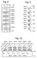
- FIG. 8is a top view of a NAND string.
- FIG. 9is an equivalent circuit diagram of the NAND string.
- FIG. 10is a cross sectional view of the NAND string.
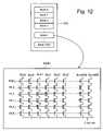
- FIG. 11is a block diagram of one embodiment of a non-volatile memory system.
- FIG. 12illustrates an example of an organization of a memory array.
- FIG. 13is a flow chart describing one embodiment of a process for programming pages of a memory system.
- FIG. 14is a flow chart describing one embodiment of a process for programming a page of a memory system.
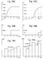
- FIGS. 15A , 15 B and 15 Care graphs depicting threshold voltage distributions.
- FIGS. 16A , 16 B and 16 Cdepict one embodiment of a programming process that reduces over programming.
- FIGS. 17A , 17 B and 17 Cdepict one embodiment of a programming process that reduces over programming.
- FIGS. 18A , 18 B and 18 Cdepict one embodiment of a programming process that reduces over programming.
- FIGS. 19A , 19 B and 19 Cdepict one embodiment of a programming process that reduces over programming.
- FIG. 8is a top view showing one NAND string.
- FIG. 9is an equivalent circuit thereof.
- the NAND string depicted in FIGS. 8 and 9includes four transistors 100 , 102 , 104 and 106 in series and sandwiched between a select gate 120 and a second select gate 122 .
- Select gate 120connects the NAND string to bit line contact 126 .
- Select gate 122connects the NAND string to source line contact 128 .
- Select gate 120is controlled by the applying appropriate voltages to control gate 120 CG.
- Select gate 122is controlled by applying the appropriate voltages to control gate 122 CG.
- Each of the transistors 100 , 102 , 104 and 106has a control gate and a floating gate.
- Transistor 100has control gate 100 CG and floating gate 100 FG.
- Transistor 102includes control gate 102 CG and floating gate 102 FG.
- Transistor 104includes control gate 104 CG and floating gate 104 FG.
- Transistor 106includes a control gate 106 CG and floating gate 106 FG.
- Control gate 100 CGis connected to word line WL 3
- control gate 102 CGis connected to word line WL 2
- control gate 104 CGis connected to word line WL 1
- control gate 106 CGis connected to word line WL 0 .
- transistors 100 , 102 , 104 and 106are each memory cells. In other embodiments, the memory cells may include multiple transistors or may be different than that depicted in FIGS. 8 and 9 .
- Select gate 120is connected to select line SGD, and select gate 122 is connected to select line SGS.
- FIG. 10provides a cross-sectional view of the NAND string described above.
- the transistors of the NAND stringare formed in p-well region 140 .
- Each transistorincludes a stacked gate structure that consists of the control gate ( 100 CG, 102 CG, 104 CG and 106 CG) and a floating gate ( 100 FG, 102 FG, 104 FG and 106 FG).
- the floating gatesare formed on the surface of the p-well on top of an oxide film.
- the control gateis above the floating gate, with an inter-polysilicon dielectric layer separating the control gate and floating gate.
- the control gates of the memory cells( 100 , 102 , 104 , 106 ) form the word lines.
- N+ diffused layers 130 , 132 , 134 , 136 and 138are shared between neighboring cells, whereby the cells are connected to one another in series to form a NAND string. These N+ diffused layers form the source and drain of each of the cells.
- N+ diffused layer 130serves as the drain of transistor 122 and the source for transistor of 106
- N+ diffused layer 132serves as the drain for transistor 106 and the source for transistor 104
- N+ diffused region 134serves as the drain for transistor 104 and the source for transistor 102
- N+ diffused region 136serves as the drain for transistor 102 and the source for transistor 100
- N+ diffused layer 138serves as the drain for transistor 100 and the source for transistor 120 .
- N+ diffused layer 126connects to the bit line for the NAND string
- N+ diffused layer 128connects to a common source line for multiple NAND strings.
- FIGS. 8–10show four memory cells in the NAND string, the use of four transistors is only provided as an example.
- a NAND stringcan have less than four memory cells or more than four memory cells.
- some NAND stringswill include 8 memory cells, 16 memory cells, 32 memory cells, etc. The discussion herein is not limited to any particular number of memory cells in a NAND string.
- Each memory cellcan store data represented in analog or digital form.
- the range of possible threshold voltages of the memory cellis divided into two ranges which are assigned logical data “1” and “0.”
- the voltage thresholdis negative after the memory cell is erased, and defined as logic “1.”
- the threshold voltage after a program operationis positive and defined as logic “0.”
- the memory cellwill turn on to indicate logic one is being stored.
- the threshold voltageis positive and a read operation is attempted, the memory cell will not turn on, which indicates that logic zero is stored.
- a memory cellcan also store multiple levels of information, thereby, storing multiple bits of digital data.
- the range of possible threshold voltagesis divided into the number of storage levels. For example, if four levels of information are stored, there will be four threshold voltage ranges assigned to the data values “11”, “10”, “01”, and “00.” In one example of a NAND type memory, the threshold voltage after an erase operation is negative and defined as “11”. Positive threshold voltages are used for the states of “10”, “01”, and “00.”
- the technology described hereinis not limited to floating gate type of memories, but may also be applicable to memory cells that use other types of material for the charge storage.
- the technology described hereincan be used with memory devices that uses various types of charge storage regions/layer(s) between the control gate (or wordline) and the substrate, such as a nitride layer or small silicon islands, better known as nano-crystals.
- FIG. 11is a block diagram of one embodiment of a flash memory system that can be used to implement the present invention.
- Memory cell array 202is controlled by column control circuit 204 , row control circuit 206 , c-source control circuit 210 and p-well control circuit 208 .
- Column control circuit 204is connected to the bit lines of memory cell array 202 for reading data stored in the memory cells, for determining a state of the memory cells during a program operation, and for controlling potential levels of the bit lines to promote the programming or to inhibit the programming.
- Row control circuit 206is connected to the word lines to select one of the word lines, to apply read voltages, to apply program voltages and to apply an erase voltage.
- C-source control circuit 210controls a common source line (labeled as “C-source” in FIG. 12 ) connected to the memory cells.
- P-well control circuit 208controls the p-well voltage.
- the data stored in the memory cellsare read out by the column control circuit 204 and are output to external I/O lines via data input/output buffer 212 .
- Program data to be stored in the memory cellsare input to the data input/output buffer 212 via the external I/O lines, and transferred to the column control circuit 204 .
- the external I/O linesare connected to controller 218 .
- Command data for controlling the flash memory deviceis input to controller 218 .
- the command datainforms the flash memory of what operation is requested.
- the input commandis transferred to state machine 216 , which controls column control circuit 204 , row control circuit 206 , c-source control 210 , p-well control circuit 208 and data input/output buffer 212 .
- State machine 216can also output status data of the flash memory such as READY/BUSY or PASS/FAIL.
- Controller 218is connected or connectable with a host system such as a personal computer, a digital camera, personal digital assistant, etc. Controller 218 communicates with the host in order to receive commands from the host, receive data from the host, provide data to the host and provide status information to the host. Controller 218 converts commands from the host into command signals that can be interpreted and executed by command circuits 214 , which is in communication with state machine 216 . Controller 218 typically contains buffer memory for the user data being written to or read from the memory array.
- One exemplar memory systemcomprises one integrated circuit that includes controller 218 , and one or more integrated circuit chips that each contain a memory array and associated control, input/output and state machine circuits.
- the trendis to integrate the memory arrays and controller circuits of a system together on one or more integrated circuit chips.
- the memory systemmay be embedded as part of the host system, or may be included in a memory card (or other package) that is removably inserted into the host systems.
- a removable cardmay include the entire memory system (e.g. including the controller) or just the memory array(s) and associated peripheral circuits (with the Controller being embedded in the host).
- the controlleror control capability
- control circuitsmay include any one of or a combination of a command circuit, a state machine, a row control circuit, a column control circuit, a well control circuit, a source control circuit or a data I/O circuit.
- FIG. 12shows four memory cells connected in series to form a NAND string. Although four cells are shown to be included in each NAND string, more or less than four memory cells can be used. One terminal of the NAND string is connected to corresponding bit line via a select transistor SGD, and another terminal is connected to c-source via a second select transistor SGS.
- 4,256 memory cellsare simultaneously selected.
- the memory cells selectedhave the same word line and the same kind of bit line (e.g. even bit lines or odd bit lines). Therefore, 532 bytes of data can be read or programmed simultaneously. These 532 bytes of data that are simultaneously read or programmed form a logical page. Therefore, one block can store at least eight logical pages (four word lines, each with odd and even pages).
- each memory cellstores two bits of data (e.g., multi-state memory cells), wherein each of these two bits are stored in a different page, one block stores 16 logical pages.
- Other sized blocks and pagescan also be used with the present invention. Additionally, architectures other than that of FIGS. 11 and 12 can also be used to implement the present invention.
- Memory cellsare erased by raising the p-well to an erase voltage (e.g. 20 volts) and grounding the word lines of a selected block.
- the source and bit linesare floating. Erasing can be performed on the entire memory array, separate blocks, or another unit of cells. Electrons are transferred from the floating gate to the p-well region and the threshold voltage becomes negative (in one embodiment).
- the select gates (SGD and SGS) and the unselected word lines (e.g., WL 0 , WL 2 and WL 3 )are raised to a read pass voltage (e.g. 4.5 volts) to make the transistors operate as pass gates.
- the selected word line (e.g. WL 1 )is connected to a voltage, a level of which is specified for each read and verify operation in order to determine whether a threshold voltage of the concerned memory cell is above or below such level. For example, in a read operation for a two level memory cell, the selected word line WL 1 may be grounded, so that it is detected whether the threshold voltage is higher than 0V.
- the selected word line WL 1is connected to 0.8V, for example, so that it is verified whether or not the threshold voltage has reached at least 0.8V.
- the source and p-wellare at zero volts.
- the selected bit lines (BLe)are pre-charged to a level of, for example, 0.7V. If the threshold voltage is higher than the read or verify level on the word line, the potential level of the bit line (BLe) associated with the cell of interest maintains the high level because of the non-conductive memory cell.
- the threshold voltageis lower than the read or verify level, the potential level of the concerned bit line (BLe) decreases to a low level, for example less than 0.5V, because of the conductive memory cell discharging the bitline.
- the state of the memory cellis thereby detected by a voltage comparator sense amplifier that is connected to the bit line.
- Vpgmprogram voltage
- Vpgmprogram voltage
- the choice of the magnitude of Vpgmis a compromise. Too high of a value will result in more fast cells being over-programmed, while a too low of a value will result in an unreasonable reduction in the programming speed.
- the number of fast cells that may cause over-programmingis relatively small in comparison to the total number of memory cells in a memory system. As a result, when a page of memory cells is programmed, the probability that there will be one or more fast memory cell in such a page is not very high.
- a low initial value for Vpgmis used for the first programming pulse such that no memory cells (or only a small number of memory cells) will be over-programmed during the first programming pulse (or first two or three pulses).
- the subsequent programming pulseswill be increased in magnitude with a larger step size (e.g., 0.6 v, instead of a typical value of 0.3 v).
- the value of Vpgmwill be quickly increased by the larger step size until the first set of one or more cells (or other minimum number) have reached an initial verify level (Vvstart).
- Vvstartinitial verify level
- fast memory cellsIn the case where one or more fast memory cells are present in a page being programmed, then these fast memory cells would be detected after the first pulse. However, depending on what value for Vpgm is used, more then one program pulse maybe needed before any fast cells are detected. In some pages, a fast cell or cells maybe detected after the first pulse, in other pages a fast cell or cells maybe detected after two or more pulses, while in other pages, no fast cells maybe detected at all. Subsequent programming pulses will be increased with a smaller step size in order to avoid over-programming of those fast memory cells. Such a page with fast memory cells would need a large number of programming pulses since the step size is small from the beginning. Since a majority of the pages in the memory array will not have any fast cells and, therefore, will not be slowed down too much, the overall programming speed will not unreasonably suffer. Only for pages where it is needed, the programming will be slower to avoid over-programming.
- FIG. 13is a flow chart describing one embodiment of a process for programming a memory system.
- command circuits 214receives a command from controller 318 to program a set of data.
- the datais received.
- step 304the system determines which pages of data need to be programmed. After determining which pages to program, state machine 216 will direct the programming of the appropriate pages.
- step 306the next page is programmed.
- step 308it is determined whether the operation was successful. If the page was programmed successfully, then it is determined whether there are more pages to program (step 310 ). If there are no more pages to program, then the process of FIG. 13 is completed. If there are more pages to program, then the process loops back to step 306 and the next page is programmed.
- Step 320can also include performing various error-correction techniques or canceling the program operation. After step 320 , the process may continue at step 310 .
- the various pages to be programmedcan also be pre-processed prior to programming. For example, pre-programming can be performed on the various pages so that all of the memory cells that were still in the erased state are programmed to a common level. After pre-programming, all of the pages can be erased. After erasing, soft programming can be performed to raise the threshold voltage of memory cells that were over-erased.
- FIG. 14is a flow chart describing one embodiment of a process for programming a page of data (see step 306 of FIG. 13 ).
- step 350data is loaded for that particular page.
- step 352the program voltage Vpgm is set to its initial low value, the increment value ⁇ Vpgm is set to a first increment value ⁇ Vpgm 1 and the program counter PC is initialized to zero.
- the value of the first program pulseis set with a magnitude low enough so that none or only a sufficiently small number of the non-volatile storage elements (even fast non-volatile storage elements) being programmed will be over-programmed (e.g., 15V).
- step 354the first program pulse is applied.
- the memory cells in a page of datashare a common word line and, thus, receive the same programming pulses at their respective control gates.
- the memory cellsare then verified against a voltage Vvstart in step 356 .
- the voltage value Vvstartis used to determine which memory cells are fast memory cells. It is chosen by device characterization so that any cells that pass Vvstart after one programming pulse are considered fast memory cells.
- step 360the program voltage is incremented by ⁇ Vpgm 1 and the program counter PC is incremented by 1. Note that in some embodiments it maybe preferred to increase the program counter with a different value than 1 in order to reflect the larger step size. For example, the loop counter could be increased by a value of 2 in case the larger step size is two times larger than the smaller step size.
- the processloops back to step 354 and the next program pulse is applied. Step 354 – 358 will be iterated until at least one memory cell has a threshold voltage greater than Vvstart.
- step 358will use a different minimum number (other than one memory cell) to test whether there are a sufficient number of memory cells with a threshold voltage greater than Vvstart.
- the number usedvaries by implementation. However, the number tested should be a number less than all of the memory cells that are successfully programmed.
- step 374the process continues as step 374 , at which time all of the memory cells are verified against the various verify levels for the different program states.
- the iterations of step 354 – 360include only verifying the memory cells against Vvstart in order to find one or more (or another minimum number) of memory cells that have a threshold voltage greater than Vvstart. After one or more memory cells are found to have a threshold voltage greater than Vvstart, all memory cells are verified against the various targets (or targets and coarse/fine verify levels, as appropriate by the implementation). For example, if coarse/fine programming is used, each memory cell will be verified against a coarse/fine verify level and a final target verify level for each of the various program states (step 374 ).
- coarse/fine algorithmscan be implemented, it is for example possible to verify first only against a coarse level of a certain desired state and start verifying against a fine level after the first cell has passed the coarse level of that state. Furthermore, if multiple levels are programmed at the same time, coarse/fine programming for the higher levels can be postponed for a certain number of programming pulses. Another possibility is to start coarse verifying for the higher levels a certain number of pulses after coarse verifying of a lower state has detected one or more cells passing that lower state coarse level. Using the above methods, the total number of required verify operations can be minimized, thereby reducing the total required programming time.
- the processis complete and status is set to pass (step 378 ).
- the programming processcan complete successfully if less than all memory cells reach their intended target. For example, in some embodiments if almost all memory cells reach their intended target (e.g., with no more than a predetermined number of cells not reaching their target), the process is successful. Memory cells that have not reached their target can be taken care of when read using error correction or the data can be programmed elsewhere in the memory array in case too many cells have failed to reach their target. If not all of the memory cells verify (which is likely the first time step 374 is performed), then it is determined whether the program counter is less than 20 (or another suitable value).
- step 382If the program counter is at 20 (or any other suitable value) or greater, then too many steps have been performed and the process fails (step 382 ). If the program counter is still less than 20 (or any other suitable value), then the program voltage is stepped by ⁇ Vpgm 2 and the program counter is incremented by one in step 370 . Note that in some embodiments, the program counter maybe incremented with a value different from one to take the difference in step sizes into account. Note that ⁇ Vpgm 2 is a smaller step size than ⁇ Vpgm 1 .
- step 372the program voltage Vpgm increases much faster during the iterations of step 354 – 360 , as compared to the slower rising of the program voltage Vpgm during the iterations of step 370 – 372 .
- step 372another program pulse is applied.
- step 374the memory cells are verified, as discussed above, and the process continues at step 376 .
- FIG. 15Ashows the threshold voltage distributions 2 , 10 , 12 , and 14 for two bit multi-state cells. Note, however, the technology described herein applies to memory cells storing more and less than two bits of data. Also depicted in FIG. 15A are read verify points Vr 1 and Vr 2 . Read verify point Vr 1 is for distinguishing between threshold voltage distributions 10 and 12 . Read verify point Vr 2 is for distinguishing between threshold voltage distributions 12 and 14 . Zero volts can be used to distinguish between threshold voltage distributions 2 and 10 .
- FIG. 15Aalso shows voltage level Vv 1 as the lowest voltage of threshold voltage distribution 10 and Vmax 1 as the upper voltage limit of voltage distribution 10 .
- FIG. 15Bshows erased threshold voltage distribution 2 and programmed threshold voltage distributions 402 and 404 when no fast memory cells are present in the page.
- verify level Vv 1represents the final target verify level and zero volts can be used as Vvstart.
- the threshold voltage distribution 402 after the first pulseshifts up from the erased level to a certain extent; however, none of the memory cells have reached the Vvstart (0 v) yet, so programming continues with a second pulse that has a Vpgm increased by the increment ⁇ Vpgm 1 .
- the threshold voltage distributionshifts up with a value close to ⁇ Vpgm 1 . Note that this amount of shift may vary and strongly depends on the amplitude of the initial Vpgm pulse.
- a number of memory cells in distribution 404have reached a threshold voltage above Vvstart (0 volts).
- Vpgmwill be subsequently increased with the smaller step size ⁇ Vpgm 2 .
- FIG. 15 cshows erased threshold voltage distribution 2 and programmed threshold voltage distribution 410 when fast memory cells are present.
- the first programming pulsee.g., threshold voltage distribution 410
- a number of cellshave a threshold voltage greater than the Vvstart (0 volts).
- Some memory cellsmay have a threshold voltage greater than Vv 1 .
- the step size for the following programming pulsewill be equal to ⁇ Vpgm 2 to avoid over-programming.
- FIGS. 16 and 17include graphs that depict the use of the technology described in conjunction with coarse/fine programming.
- FIGS. 16A , 16 B, and 16 Cdepict the behavior of a fast memory cell which has a threshold voltage that passes both the course and target verify levels in the same pulse so that the memory cell does not enter the fine mode.
- FIGS. 17A , 17 B, and 17 Cdepict a slower memory cell that participates in both the coarse and fine modes.
- FIGS. 16A and 17Adepict programming pulses Vpgm applied to the control gates of the memory cells being programmed.
- FIGS. 16B and 17Bdepict bit line voltages Vb 1 for the memory cells being programmed.
- FIGS. 16C and 17Cdepict the threshold voltages for the memory cells being programmed.
- Vver 3In response to a first pulse that starts at time t 0 , the memory cell's threshold voltage is raised above Vver 3 . Note that the verify level Vver 3 corresponds to Vvstart of FIG. 14 . Therefore, the page that includes this memory cell is programmed more slowly. As such, the magnitude of subsequent programming pulse will increase by ⁇ Vpgm 2 . In between t 1 and t 2 , the threshold voltage of the memory cell rises above both Vver 2 and Vver 1 . At t 2 , the bit line voltage will be raised to Vinhibit in order to inhibit any further programming. Note that in one embodiment, Vver 3 may be 0.2 v to 0.3 v lower than the Vver 2 for the lowest programmed state.
- the threshold voltage of the memory cellwill not rise above Vver 3 until the period between t 2 and t 3 .
- programming pulseswill increment by ⁇ Vpgm 1 prior to t 3 .
- the threshold voltage in the memory cell in the pageis greater than Vver 3 at t 3 , then the increment value is changed at t 3 to ⁇ Vpgm 2 , and subsequent pulses increase in magnitude by ⁇ Vpgm 2 .
- the threshold voltage in the memory cellincreases above Vver 2 between t 3 and t 4 , therefore, the memory cell enters the fine programming phase and the bit line is raised to Vs at t 4 .
- the threshold voltage increaseis slowed down due to the increase in bit line voltage and due to the decrease in the Vpgm increment value.
- the threshold voltagedoes become greater than Vver 1 between t 4 and t 5 ; therefore, the threshold voltage has reached its target level and the bit line voltage is raised to Vinhibit in order to inhibit further programming at t 5 .
- FIGS. 16A and 17Ashow the programming pulses adjacent each to each other to make the graph easier to read. However, there are actually time spaces between the pulse to allow for the verify operations.
- FIGS. 18 and 19describe another embodiment for using the technology described herein to avoid or reduce over-programming.
- This embodimentpertains to an initial set of one or more pulses until one or more memory cells reach the Vver 3 level and then resetting the program voltage magnitude to a lower level for subsequent programming pulses.
- This embodimentalso uses the coarse/fine methodology.
- FIGS. 18A , 18 B, and 18 Ccorrespond to a fast memory cell
- FIGS. 19A , 19 B, and 19 Ccorrespond to a slower memory cell.
- FIGS. 18A and 19Adepict the program pulses Vpgm.
- FIGS. 18B and 19Bdepict the bit line voltage Vb 1 .
- FIGS. 18C and 19Cdepict the threshold voltage of the memory cell being programmed over time.
- a first pulseis provided at time t 0 .
- the magnitude of this first pulseis determined so that no or only a sufficiently small number of memory cells will be over-programmed.
- FIG. 18Cshows a fast memory cell with a threshold voltage that becomes higher than Vver 3 in between times t 0 and t 1 . Therefore, the associated page of memory cells will be programmed slower using ⁇ Vpgm 2 .
- the magnitude of Vpgmis lowered, for example by a value of 0.3–0.5V.
- FIG. 18Ashows the magnitude of the pulse starting at t 1 to be lower than the magnitude of the pulse that starts at t 0 .
- each subsequent pulseis increased by ⁇ Vpgm 2 .
- the threshold voltage of the memory cellis raised to a level higher than Vver 1 ; therefore, the bit line is raised to Vinhibit at t 2 (See FIG. 18B ).
- FIG. 19Ashows the case where the memory cell programs more slowly.
- the memory celldoes not have its threshold voltage reach Vver 3 until the period between t 2 and t 3 . Therefore, prior to t 3 , the pulses are incremented by ⁇ Vpgm 1 . After t 3 , the increment value for Vpgm will be changed to ⁇ Vpgm 2 . Additionally, the magnitude of the pulses will be reset to a lower value.
- FIG. 19 ashows the pulse starting at t 3 to be lower than the pulse starting at t 2 . The increment value for additional pulses after t 3 is ⁇ Vpgm 2 .
- the threshold voltageis greater than Vver 2 , but less that Vver 1 , therefore, the memory cell enters the fine programming phase and the bit line voltage is raised to Vs.
- the threshold voltage of the memory cellis greater than Vver 1 ; therefore, the memory cell is inhibit from further programming by raising the bit line voltage to Vinhibit.
Landscapes
- Engineering & Computer Science (AREA)
- Computer Hardware Design (AREA)
- Microelectronics & Electronic Packaging (AREA)
- Read Only Memory (AREA)
- Stored Programmes (AREA)
Abstract
Description
Claims (44)
Priority Applications (11)
| Application Number | Priority Date | Filing Date | Title |
|---|---|---|---|
| US10/990,702US7092290B2 (en) | 2004-11-16 | 2004-11-16 | High speed programming system with reduced over programming |
| US11/099,259US7173859B2 (en) | 2004-11-16 | 2005-04-05 | Faster programming of higher level states in multi-level cell flash memory |
| AT05817284TATE492882T1 (en) | 2004-11-16 | 2005-11-03 | FAST PROGRAMMING SYSTEM WITH REDUCED OVERPROGRAMMING |
| CN2005800392083ACN101095199B (en) | 2004-11-16 | 2005-11-03 | Non-volatile memory system and method for programming non-volatile memory |
| PCT/US2005/039735WO2006055256A1 (en) | 2004-11-16 | 2005-11-03 | High speed programming system with reduced over programming |
| KR1020077011282AKR20070101240A (en) | 2004-11-16 | 2005-11-03 | High speed programming system reduces over programming |
| DE602005025522TDE602005025522D1 (en) | 2004-11-16 | 2005-11-03 | FAST PROGRAMMING SYSTEM WITH REDUCED OVERPROGRAMMING |
| KR1020097006837AKR100909721B1 (en) | 2004-11-16 | 2005-11-03 | High speed programming system reduces over programming |
| JP2007541243AJP4857278B2 (en) | 2004-11-16 | 2005-11-03 | High-speed programming system that uses reduced overprogramming |
| EP05817284AEP1812932B1 (en) | 2004-11-16 | 2005-11-03 | High speed programming system with reduced over programming |
| TW094140086ATWI301981B (en) | 2004-11-16 | 2005-11-15 | Non-volatile storage system and method for programming non-volatile storage |
Applications Claiming Priority (1)
| Application Number | Priority Date | Filing Date | Title |
|---|---|---|---|
| US10/990,702US7092290B2 (en) | 2004-11-16 | 2004-11-16 | High speed programming system with reduced over programming |
Related Child Applications (1)
| Application Number | Title | Priority Date | Filing Date |
|---|---|---|---|
| US11/099,259Continuation-In-PartUS7173859B2 (en) | 2004-11-16 | 2005-04-05 | Faster programming of higher level states in multi-level cell flash memory |
Publications (2)
| Publication Number | Publication Date |
|---|---|
| US20060104120A1 US20060104120A1 (en) | 2006-05-18 |
| US7092290B2true US7092290B2 (en) | 2006-08-15 |
Family
ID=35788987
Family Applications (1)
| Application Number | Title | Priority Date | Filing Date |
|---|---|---|---|
| US10/990,702Expired - LifetimeUS7092290B2 (en) | 2004-11-16 | 2004-11-16 | High speed programming system with reduced over programming |
Country Status (9)
| Country | Link |
|---|---|
| US (1) | US7092290B2 (en) |
| EP (1) | EP1812932B1 (en) |
| JP (1) | JP4857278B2 (en) |
| KR (2) | KR100909721B1 (en) |
| CN (1) | CN101095199B (en) |
| AT (1) | ATE492882T1 (en) |
| DE (1) | DE602005025522D1 (en) |
| TW (1) | TWI301981B (en) |
| WO (1) | WO2006055256A1 (en) |
Cited By (43)
| Publication number | Priority date | Publication date | Assignee | Title |
|---|---|---|---|---|
| US20060245261A1 (en)* | 2005-04-28 | 2006-11-02 | Midori Morooka | Semiconductor integrated circuit device |
| US20070025157A1 (en)* | 2005-08-01 | 2007-02-01 | Jun Wan | Method for programming non-volatile memory with self-adjusting maximum program loop |
| US20070266296A1 (en)* | 2006-05-15 | 2007-11-15 | Conley Kevin M | Nonvolatile Memory with Convolutional Coding |
| US20070266295A1 (en)* | 2006-05-15 | 2007-11-15 | Conley Kevin M | Convolutional Coding Methods for Nonvolatile Memory |
| US20080082897A1 (en)* | 2006-09-28 | 2008-04-03 | Yigal Brandman | Soft-Input Soft-Output Decoder for Nonvolatile Memory |
| US20080092026A1 (en)* | 2006-09-28 | 2008-04-17 | Yigal Brandman | Methods of Soft-Input Soft-Output Decoding for Nonvolatile Memory |
| US20080092014A1 (en)* | 2006-09-28 | 2008-04-17 | Yigal Brandman | Methods of Adapting Operation of Nonvolatile Memory |
| US20080092015A1 (en)* | 2006-09-28 | 2008-04-17 | Yigal Brandman | Nonvolatile memory with adaptive operation |
| US20080109702A1 (en)* | 2006-11-03 | 2008-05-08 | Yigal Brandman | Methods of Modulating Error Correction Coding |
| US20080109703A1 (en)* | 2006-11-03 | 2008-05-08 | Yigal Brandman | Nonvolatile Memory With Modulated Error Correction Coding |
| US20080117684A1 (en)* | 2006-11-16 | 2008-05-22 | Gerrit Jan Hemink | Systems for controlled boosting in non-volatile memory soft programming |
| US20080117683A1 (en)* | 2006-11-16 | 2008-05-22 | Gerrit Jan Hemink | Controlled boosting in non-volatile memory soft programming |
| US20080123419A1 (en)* | 2006-11-03 | 2008-05-29 | Yigal Brandman | Methods of Varying Read Threshold Voltage in Nonvolatile Memory |
| US20080123420A1 (en)* | 2006-11-03 | 2008-05-29 | Yigal Brandman | Nonvolatile Memory With Variable Read Threshold |
| US20080158980A1 (en)* | 2006-12-27 | 2008-07-03 | Teruhiko Kamei | Non-volatile storage system with initial programming voltage based on trial |
| US20080158979A1 (en)* | 2006-12-27 | 2008-07-03 | Teruhiko Kamei | Method for programming with initial programming voltage based on trial |
| US20080198662A1 (en)* | 2007-02-20 | 2008-08-21 | Nima Mokhlesi | Dynamic verify based on threshold voltage distribution |
| US20090010068A1 (en)* | 2007-07-03 | 2009-01-08 | Shih-Chung Lee | Systems for Coarse/Fine Program Verification in Non-Volatile Memory Using Different Reference Levels for Improved Sensing |
| US20090010067A1 (en)* | 2007-07-03 | 2009-01-08 | Shih-Chung Lee | Coarse/fine program verification in non-volatile memory using different reference levels for improved sensing |
| US20090323429A1 (en)* | 2008-06-27 | 2009-12-31 | Dana Lee | Programming algorithm to reduce disturb with minimal extra time penalty |
| US20100103734A1 (en)* | 2008-10-24 | 2010-04-29 | Gerrit Jan Hemink | Programming non-volatile memory with high resolution variable initial programming pulse |
| US8351276B2 (en) | 2010-07-13 | 2013-01-08 | Freescale Semiconductor, Inc. | Soft program of a non-volatile memory block |
| US8441862B2 (en) | 2010-04-12 | 2013-05-14 | Samsung Electronics Co., Ltd. | Program method of multi-bit memory device and data storage system using the same |
| US8472255B2 (en) | 2007-09-27 | 2013-06-25 | Sandisk Technologies Inc. | Compensation of non-volatile memory chip non-idealities by program pulse adjustment |
| US8582381B2 (en) | 2012-02-23 | 2013-11-12 | SanDisk Technologies, Inc. | Temperature based compensation during verify operations for non-volatile storage |
| WO2014011627A1 (en) | 2012-07-11 | 2014-01-16 | SanDisk Technologies, Inc. | Programming method to tighten threshold voltage width with avoiding program disturb |
| US8743624B2 (en) | 2008-07-02 | 2014-06-03 | SanDisk Technologies, Inc. | Programming and selectively erasing non-volatile storage |
| US8885416B2 (en) | 2013-01-30 | 2014-11-11 | Sandisk Technologies Inc. | Bit line current trip point modulation for reading nonvolatile storage elements |
| US9225356B2 (en) | 2012-11-12 | 2015-12-29 | Freescale Semiconductor, Inc. | Programming a non-volatile memory (NVM) system having error correction code (ECC) |
| US20160064094A1 (en)* | 2012-03-13 | 2016-03-03 | Micron Technology, Inc. | Nonconsecutive sensing of multilevel memory cells |
| US20170125117A1 (en)* | 2015-10-30 | 2017-05-04 | Sandisk Technologies Inc. | Smart Skip Verify Mode For Programming A Memory Device |
| TWI596477B (en)* | 2015-12-18 | 2017-08-21 | 群聯電子股份有限公司 | Memory management method, memory control circuit unit and memory storage device |
| US10249382B2 (en) | 2017-08-22 | 2019-04-02 | Sandisk Technologies Llc | Determination of fast to program word lines in non-volatile memory |
| US10248499B2 (en) | 2016-06-24 | 2019-04-02 | Sandisk Technologies Llc | Non-volatile storage system using two pass programming with bit error control |
| US10748622B2 (en) | 2019-01-21 | 2020-08-18 | Sandisk Technologies Llc | State adaptive predictive programming |
| US10839928B1 (en) | 2019-05-16 | 2020-11-17 | Sandisk Technologies Llc | Non-volatile memory with countermeasure for over programming |
| US10910075B2 (en) | 2018-11-13 | 2021-02-02 | Sandisk Technologies Llc | Programming process combining adaptive verify with normal and slow programming speeds in a memory device |
| US11049578B1 (en) | 2020-02-19 | 2021-06-29 | Sandisk Technologies Llc | Non-volatile memory with program verify skip |
| US11081198B2 (en) | 2019-05-16 | 2021-08-03 | Sandisk Technologies Llc | Non-volatile memory with countermeasure for over programming |
| US11532370B1 (en) | 2021-05-25 | 2022-12-20 | Sandisk Technologies Llc | Non-volatile memory with fast multi-level program verify |
| US11557346B2 (en) | 2021-06-02 | 2023-01-17 | Western Digital Technologies, Inc. | Self-adaptive program pulse width for programming 3D NAND memory |
| US12051473B2 (en) | 2022-06-28 | 2024-07-30 | Western Digital Technolologies, Inc. | Non-volatile memory with precise programming |
| US12094546B2 (en) | 2022-01-31 | 2024-09-17 | Sandisk Technologies Llc | Non-volatile memory with zone based program speed adjustment |
Families Citing this family (40)
| Publication number | Priority date | Publication date | Assignee | Title |
|---|---|---|---|---|
| US8511558B2 (en)* | 2005-04-12 | 2013-08-20 | Sandisk Il Ltd. | Smartcard power management |
| KR100771882B1 (en)* | 2006-09-06 | 2007-11-01 | 삼성전자주식회사 | Program method of multi-level nonvolatile memory device |
| KR100771883B1 (en) | 2006-09-06 | 2007-11-01 | 삼성전자주식회사 | Multi-level nonvolatile memory device and program method |
| US7453731B2 (en) | 2006-09-12 | 2008-11-18 | Sandisk Corporation | Method for non-volatile memory with linear estimation of initial programming voltage |
| US7606091B2 (en) | 2006-09-12 | 2009-10-20 | Sandisk Corporation | Method for non-volatile memory with reduced erase/write cycling during trimming of initial programming voltage |
| US7606077B2 (en) | 2006-09-12 | 2009-10-20 | Sandisk Corporation | Non-volatile memory with reduced erase/write cycling during trimming of initial programming voltage |
| EP2383748A3 (en)* | 2006-09-12 | 2012-03-28 | SanDisk Corporation | Non-volatile memory and method for linear estimation of initial programming voltage |
| US7599223B2 (en) | 2006-09-12 | 2009-10-06 | Sandisk Corporation | Non-volatile memory with linear estimation of initial programming voltage |
| US7450426B2 (en)* | 2006-10-10 | 2008-11-11 | Sandisk Corporation | Systems utilizing variable program voltage increment values in non-volatile memory program operations |
| WO2008045805A1 (en)* | 2006-10-10 | 2008-04-17 | Sandisk Corporation | Variable program voltage increment values in non-volatile memory program operations |
| US7474561B2 (en)* | 2006-10-10 | 2009-01-06 | Sandisk Corporation | Variable program voltage increment values in non-volatile memory program operations |
| JP2008140488A (en)* | 2006-12-04 | 2008-06-19 | Toshiba Corp | Semiconductor memory device |
| US7656709B2 (en)* | 2007-05-03 | 2010-02-02 | Micron Technology, Inc. | NAND step up voltage switching method |
| KR101344347B1 (en)* | 2008-01-16 | 2013-12-24 | 삼성전자주식회사 | Nonvolatile memory device controlling program start voltage, program method thereof, and memory system including the same |
| US7916544B2 (en)* | 2008-01-25 | 2011-03-29 | Micron Technology, Inc. | Random telegraph signal noise reduction scheme for semiconductor memories |
| CN102027548B (en)* | 2008-04-29 | 2014-01-01 | 桑迪士克以色列有限公司 | Non-volatile multilevel memory with adaptive setting of reference voltage levels for programming, verifying and reading |
| KR20090120205A (en) | 2008-05-19 | 2009-11-24 | 삼성전자주식회사 | Flash memory device and its operation method |
| JP2009301679A (en)* | 2008-06-17 | 2009-12-24 | Vantel Corp | Nonvolatile semiconductor storage device and its data writing method |
| US8174895B2 (en)* | 2009-12-15 | 2012-05-08 | Sandisk Technologies Inc. | Programming non-volatile storage with fast bit detection and verify skip |
| CN102129886B (en)* | 2010-01-12 | 2013-07-17 | 中芯国际集成电路制造(上海)有限公司 | Methods for initializing, setting and resetting resistive random access memory |
| US8472257B2 (en) | 2011-03-24 | 2013-06-25 | Sandisk Technologies Inc. | Nonvolatile memory and method for improved programming with reduced verify |
| JP2011204356A (en)* | 2011-07-19 | 2011-10-13 | Toshiba Corp | Nonvolatile semiconductor memory device |
| KR102053953B1 (en)* | 2013-02-04 | 2019-12-11 | 삼성전자주식회사 | Memory system comprising nonvolatile memory device and program method thereof |
| US9105360B2 (en)* | 2013-03-07 | 2015-08-11 | Seagate Technology Llc | Forming a characterization parameter of a resistive memory element |
| KR20150091684A (en)* | 2014-02-03 | 2015-08-12 | 에스케이하이닉스 주식회사 | Semiconductor Apparatus |
| WO2017200883A1 (en) | 2016-05-17 | 2017-11-23 | Silicon Storage Technology, Inc. | Deep learning neural network classifier using non-volatile memory array |
| KR102683414B1 (en)* | 2017-01-26 | 2024-07-10 | 삼성전자주식회사 | Nonvolatile Memory Device, and Programming Method Thereof |
| US10803943B2 (en) | 2017-11-29 | 2020-10-13 | Silicon Storage Technology, Inc. | Neural network classifier using array of four-gate non-volatile memory cells |
| US10699779B2 (en) | 2017-11-29 | 2020-06-30 | Silicon Storage Technology, Inc. | Neural network classifier using array of two-gate non-volatile memory cells |
| US10748630B2 (en)* | 2017-11-29 | 2020-08-18 | Silicon Storage Technology, Inc. | High precision and highly efficient tuning mechanisms and algorithms for analog neuromorphic memory in artificial neural networks |
| US11087207B2 (en) | 2018-03-14 | 2021-08-10 | Silicon Storage Technology, Inc. | Decoders for analog neural memory in deep learning artificial neural network |
| US10522226B2 (en)* | 2018-05-01 | 2019-12-31 | Silicon Storage Technology, Inc. | Method and apparatus for high voltage generation for analog neural memory in deep learning artificial neural network |
| US10607702B1 (en)* | 2018-12-03 | 2020-03-31 | Micron Technology, Inc. | Responding to power loss |
| US11409352B2 (en) | 2019-01-18 | 2022-08-09 | Silicon Storage Technology, Inc. | Power management for an analog neural memory in a deep learning artificial neural network |
| US11023559B2 (en) | 2019-01-25 | 2021-06-01 | Microsemi Soc Corp. | Apparatus and method for combining analog neural net with FPGA routing in a monolithic integrated circuit |
| US11270771B2 (en) | 2019-01-29 | 2022-03-08 | Silicon Storage Technology, Inc. | Neural network classifier using array of stacked gate non-volatile memory cells |
| US11423979B2 (en) | 2019-04-29 | 2022-08-23 | Silicon Storage Technology, Inc. | Decoding system and physical layout for analog neural memory in deep learning artificial neural network |
| CN112201293B (en)* | 2020-10-18 | 2023-12-15 | 本征信息技术(苏州)有限公司 | Programming method of multi-level cell nonvolatile memory |
| US12354680B2 (en) | 2022-09-30 | 2025-07-08 | SanDisk Technologies, Inc. | High performance verify techniques in a memory device |
| CN118072798A (en)* | 2022-11-23 | 2024-05-24 | 长江存储科技有限责任公司 | A method for improving programming operations in a 3D NAND system |
Citations (26)
| Publication number | Priority date | Publication date | Assignee | Title |
|---|---|---|---|---|
| US5220531A (en) | 1991-01-02 | 1993-06-15 | Information Storage Devices, Inc. | Source follower storage cell and improved method and apparatus for iterative write for integrated circuit analog signal recording and playback |
| US5313421A (en) | 1992-01-14 | 1994-05-17 | Sundisk Corporation | EEPROM with split gate source side injection |
| US5386422A (en) | 1991-03-12 | 1995-01-31 | Kabushiki Kaisha Toshiba | Electrically erasable and programmable non-volatile memory system with write-verify controller using two reference levels |
| US5412601A (en) | 1992-08-31 | 1995-05-02 | Nippon Steel Corporation | Non-volatile semiconductor memory device capable of storing multi-value data in each memory cell |
| US5521865A (en) | 1994-03-15 | 1996-05-28 | Kabushiki Kaisha Toshiba | Non-volatile semiconductor memory device for storing multi-value data |
| US5570315A (en) | 1993-09-21 | 1996-10-29 | Kabushiki Kaisha Toshiba | Multi-state EEPROM having write-verify control circuit |
| US5712815A (en) | 1996-04-22 | 1998-01-27 | Advanced Micro Devices, Inc. | Multiple bits per-cell flash EEPROM capable of concurrently programming and verifying memory cells and reference cells |
| US5712180A (en) | 1992-01-14 | 1998-01-27 | Sundisk Corporation | EEPROM with split gate source side injection |
| US5761222A (en) | 1994-09-30 | 1998-06-02 | Sgs-Thomson Microelectronics, S.R.L. | Memory device having error detection and correction function, and methods for reading, writing and erasing the memory device |
| WO1998028745A1 (en) | 1996-12-20 | 1998-07-02 | Intel Corporation | Nonvolatile writeable memory with fast programming capability |
| US5870344A (en) | 1996-03-14 | 1999-02-09 | Fujitsu Limited | Semiconductor memory device |
| US5949714A (en) | 1994-09-17 | 1999-09-07 | Kabushiki Kaisha Toshiba | Nonvolatile semiconductor memory device |
| US6151248A (en) | 1999-06-30 | 2000-11-21 | Sandisk Corporation | Dual floating gate EEPROM cell array with steering gates shared by adjacent cells |
| US6222762B1 (en) | 1992-01-14 | 2001-04-24 | Sandisk Corporation | Multi-state memory |
| US6266270B1 (en) | 1998-07-23 | 2001-07-24 | Sony Corporation | Non-volatile semiconductor memory and programming method of the same |
| US6278632B1 (en) | 1996-10-24 | 2001-08-21 | Micron Technology, Inc. | Method and circuitry for performing analog over-program and under-program detection for a multistate memory cell |
| US6301161B1 (en) | 2000-04-25 | 2001-10-09 | Winbond Electronics Corporation | Programming flash memory analog storage using coarse-and-fine sequence |
| US6373748B2 (en)* | 2000-04-27 | 2002-04-16 | Kabushiki Kaisha Toshiba | Nonvolatile semiconductor memory |
| US6424566B1 (en) | 2001-02-08 | 2002-07-23 | Advanced Micro Devices, Inc. | Program reconnaissance to eliminate variations in vt distributions of multi-level cell flash memory designs |
| US20020118574A1 (en) | 2001-02-26 | 2002-08-29 | Geoffrey Gongwer | Non-volatile memory with improved programming and method therefor |
| US6522580B2 (en) | 2001-06-27 | 2003-02-18 | Sandisk Corporation | Operating techniques for reducing effects of coupling between storage elements of a non-volatile memory operated in multiple data states |
| US6525964B2 (en) | 1997-04-07 | 2003-02-25 | Kabushiki Kaisha Toshiba | Semiconductor memory device |
| US6529412B1 (en) | 2002-01-16 | 2003-03-04 | Advanced Micro Devices, Inc. | Source side sensing scheme for virtual ground read of flash eprom array with adjacent bit precharge |
| US6532172B2 (en) | 2001-05-31 | 2003-03-11 | Sandisk Corporation | Steering gate and bit line segmentation in non-volatile memories |
| US6535428B2 (en)* | 2001-06-14 | 2003-03-18 | Stmicroelectronics S.R.L. | Sensing circuit for memory cells |
| US20030147278A1 (en) | 2001-12-27 | 2003-08-07 | Kabushiki Kaisha Toshiba | Non-volatile semiconductor memory device adapted to store a multi-valued data in a single memory cell |
Family Cites Families (6)
| Publication number | Priority date | Publication date | Assignee | Title |
|---|---|---|---|---|
| TWI267704B (en)* | 1999-07-02 | 2006-12-01 | Asml Netherlands Bv | Capping layer for EUV optical elements |
| KR100322470B1 (en)* | 1999-07-22 | 2002-02-07 | 윤종용 | High-density nor-type flash memory device and a programming method thereof |
| US6493266B1 (en)* | 2001-04-09 | 2002-12-10 | Advanced Micro Devices, Inc. | Soft program and soft program verify of the core cells in flash memory array |
| JP4050555B2 (en)* | 2002-05-29 | 2008-02-20 | 株式会社東芝 | Nonvolatile semiconductor memory device and data writing method thereof |
| JP4181363B2 (en)* | 2002-08-29 | 2008-11-12 | スパンション エルエルシー | Nonvolatile semiconductor memory device and data writing method |
| JP2004103089A (en)* | 2002-09-06 | 2004-04-02 | Sharp Corp | Nonvolatile semiconductor memory device and rewriting method thereof |
- 2004
- 2004-11-16USUS10/990,702patent/US7092290B2/ennot_activeExpired - Lifetime
- 2005
- 2005-11-03KRKR1020097006837Apatent/KR100909721B1/ennot_activeExpired - Fee Related
- 2005-11-03ATAT05817284Tpatent/ATE492882T1/ennot_activeIP Right Cessation
- 2005-11-03JPJP2007541243Apatent/JP4857278B2/ennot_activeExpired - Fee Related
- 2005-11-03CNCN2005800392083Apatent/CN101095199B/enactiveActive
- 2005-11-03WOPCT/US2005/039735patent/WO2006055256A1/enactiveApplication Filing
- 2005-11-03KRKR1020077011282Apatent/KR20070101240A/ennot_activeCeased
- 2005-11-03EPEP05817284Apatent/EP1812932B1/ennot_activeNot-in-force
- 2005-11-03DEDE602005025522Tpatent/DE602005025522D1/enactiveActive
- 2005-11-15TWTW094140086Apatent/TWI301981B/ennot_activeIP Right Cessation
Patent Citations (30)
| Publication number | Priority date | Publication date | Assignee | Title |
|---|---|---|---|---|
| US5220531A (en) | 1991-01-02 | 1993-06-15 | Information Storage Devices, Inc. | Source follower storage cell and improved method and apparatus for iterative write for integrated circuit analog signal recording and playback |
| US5386422A (en) | 1991-03-12 | 1995-01-31 | Kabushiki Kaisha Toshiba | Electrically erasable and programmable non-volatile memory system with write-verify controller using two reference levels |
| US5313421A (en) | 1992-01-14 | 1994-05-17 | Sundisk Corporation | EEPROM with split gate source side injection |
| US6317364B1 (en) | 1992-01-14 | 2001-11-13 | Sandisk Corporation | Multi-state memory |
| US5712180A (en) | 1992-01-14 | 1998-01-27 | Sundisk Corporation | EEPROM with split gate source side injection |
| US6222762B1 (en) | 1992-01-14 | 2001-04-24 | Sandisk Corporation | Multi-state memory |
| US5412601A (en) | 1992-08-31 | 1995-05-02 | Nippon Steel Corporation | Non-volatile semiconductor memory device capable of storing multi-value data in each memory cell |
| US5652719A (en) | 1993-09-21 | 1997-07-29 | Kabushiki Kaisha Toshiba | Nonvolatile semiconductor memory device |
| US5570315A (en) | 1993-09-21 | 1996-10-29 | Kabushiki Kaisha Toshiba | Multi-state EEPROM having write-verify control circuit |
| US5521865A (en) | 1994-03-15 | 1996-05-28 | Kabushiki Kaisha Toshiba | Non-volatile semiconductor memory device for storing multi-value data |
| US5949714A (en) | 1994-09-17 | 1999-09-07 | Kabushiki Kaisha Toshiba | Nonvolatile semiconductor memory device |
| US5761222A (en) | 1994-09-30 | 1998-06-02 | Sgs-Thomson Microelectronics, S.R.L. | Memory device having error detection and correction function, and methods for reading, writing and erasing the memory device |
| US5870344A (en) | 1996-03-14 | 1999-02-09 | Fujitsu Limited | Semiconductor memory device |
| US5712815A (en) | 1996-04-22 | 1998-01-27 | Advanced Micro Devices, Inc. | Multiple bits per-cell flash EEPROM capable of concurrently programming and verifying memory cells and reference cells |
| US6278632B1 (en) | 1996-10-24 | 2001-08-21 | Micron Technology, Inc. | Method and circuitry for performing analog over-program and under-program detection for a multistate memory cell |
| WO1998028745A1 (en) | 1996-12-20 | 1998-07-02 | Intel Corporation | Nonvolatile writeable memory with fast programming capability |
| US6525964B2 (en) | 1997-04-07 | 2003-02-25 | Kabushiki Kaisha Toshiba | Semiconductor memory device |
| US6266270B1 (en) | 1998-07-23 | 2001-07-24 | Sony Corporation | Non-volatile semiconductor memory and programming method of the same |
| US6151248A (en) | 1999-06-30 | 2000-11-21 | Sandisk Corporation | Dual floating gate EEPROM cell array with steering gates shared by adjacent cells |
| US6301161B1 (en) | 2000-04-25 | 2001-10-09 | Winbond Electronics Corporation | Programming flash memory analog storage using coarse-and-fine sequence |
| US6373748B2 (en)* | 2000-04-27 | 2002-04-16 | Kabushiki Kaisha Toshiba | Nonvolatile semiconductor memory |
| US6424566B1 (en) | 2001-02-08 | 2002-07-23 | Advanced Micro Devices, Inc. | Program reconnaissance to eliminate variations in vt distributions of multi-level cell flash memory designs |
| US20020118574A1 (en) | 2001-02-26 | 2002-08-29 | Geoffrey Gongwer | Non-volatile memory with improved programming and method therefor |
| US6738289B2 (en) | 2001-02-26 | 2004-05-18 | Sandisk Corporation | Non-volatile memory with improved programming and method therefor |
| US6532172B2 (en) | 2001-05-31 | 2003-03-11 | Sandisk Corporation | Steering gate and bit line segmentation in non-volatile memories |
| US6535428B2 (en)* | 2001-06-14 | 2003-03-18 | Stmicroelectronics S.R.L. | Sensing circuit for memory cells |
| US6522580B2 (en) | 2001-06-27 | 2003-02-18 | Sandisk Corporation | Operating techniques for reducing effects of coupling between storage elements of a non-volatile memory operated in multiple data states |
| US20030147278A1 (en) | 2001-12-27 | 2003-08-07 | Kabushiki Kaisha Toshiba | Non-volatile semiconductor memory device adapted to store a multi-valued data in a single memory cell |
| US6643188B2 (en) | 2001-12-27 | 2003-11-04 | Kabushiki Kaisha Toshiba | Non-volatile semiconductor memory device adapted to store a multi-valued data in a single memory cell |
| US6529412B1 (en) | 2002-01-16 | 2003-03-04 | Advanced Micro Devices, Inc. | Source side sensing scheme for virtual ground read of flash eprom array with adjacent bit precharge |
Non-Patent Citations (4)
| Title |
|---|
| Johnson, William S., et al., Session XII: ROMs, PROMs and EROMs, 1980 IEEE International Solid State Circuits Conference, pp. 152-153. |
| Kurata, Hideaki, et al., Constant-Charge-Injection Programming for 10-MB/s Multilevel AG-AND Flash Memories, 2002 Symposium On VLSI Circuits Digest of Technical Papers, pp. 302-303. |
| Nobukata, Hiromi, et al., A 144Mb 8-Level NAND Flash Memory with Optimized Pulse Width Programming, 1999 Symposium on VLSI Circuits Digest of Technical Papers, pp. 39-40. |
| Ohkawa, Masayoshi, et al., TP 2.3: A 98 mm2 3.3V 64 Mb Flash Memory with FN-NOR Type 4-level Cell, 1996 IEEE International Solid-State Circuits Conference, pp. 36-37. |
Cited By (89)
| Publication number | Priority date | Publication date | Assignee | Title |
|---|---|---|---|---|
| US7564713B2 (en)* | 2005-04-28 | 2009-07-21 | Kabushiki Kaisha Toshiba | Semiconductor integrated circuit device wherein during data write a potential transferred to each bit line is changed in accordance with program order of program data |
| US20060245261A1 (en)* | 2005-04-28 | 2006-11-02 | Midori Morooka | Semiconductor integrated circuit device |
| US20070025157A1 (en)* | 2005-08-01 | 2007-02-01 | Jun Wan | Method for programming non-volatile memory with self-adjusting maximum program loop |
| US7230854B2 (en)* | 2005-08-01 | 2007-06-12 | Sandisk Corporation | Method for programming non-volatile memory with self-adjusting maximum program loop |
| US7840875B2 (en) | 2006-05-15 | 2010-11-23 | Sandisk Corporation | Convolutional coding methods for nonvolatile memory |
| US20070266296A1 (en)* | 2006-05-15 | 2007-11-15 | Conley Kevin M | Nonvolatile Memory with Convolutional Coding |
| US20070266295A1 (en)* | 2006-05-15 | 2007-11-15 | Conley Kevin M | Convolutional Coding Methods for Nonvolatile Memory |
| US20080092026A1 (en)* | 2006-09-28 | 2008-04-17 | Yigal Brandman | Methods of Soft-Input Soft-Output Decoding for Nonvolatile Memory |
| US20080092015A1 (en)* | 2006-09-28 | 2008-04-17 | Yigal Brandman | Nonvolatile memory with adaptive operation |
| US7818653B2 (en) | 2006-09-28 | 2010-10-19 | Sandisk Corporation | Methods of soft-input soft-output decoding for nonvolatile memory |
| US7805663B2 (en) | 2006-09-28 | 2010-09-28 | Sandisk Corporation | Methods of adapting operation of nonvolatile memory |
| US7904783B2 (en) | 2006-09-28 | 2011-03-08 | Sandisk Corporation | Soft-input soft-output decoder for nonvolatile memory |
| US20080092014A1 (en)* | 2006-09-28 | 2008-04-17 | Yigal Brandman | Methods of Adapting Operation of Nonvolatile Memory |
| US20080082897A1 (en)* | 2006-09-28 | 2008-04-03 | Yigal Brandman | Soft-Input Soft-Output Decoder for Nonvolatile Memory |
| US8001441B2 (en) | 2006-11-03 | 2011-08-16 | Sandisk Technologies Inc. | Nonvolatile memory with modulated error correction coding |
| US20080123420A1 (en)* | 2006-11-03 | 2008-05-29 | Yigal Brandman | Nonvolatile Memory With Variable Read Threshold |
| US20080109702A1 (en)* | 2006-11-03 | 2008-05-08 | Yigal Brandman | Methods of Modulating Error Correction Coding |
| US20080109703A1 (en)* | 2006-11-03 | 2008-05-08 | Yigal Brandman | Nonvolatile Memory With Modulated Error Correction Coding |
| US7904788B2 (en) | 2006-11-03 | 2011-03-08 | Sandisk Corporation | Methods of varying read threshold voltage in nonvolatile memory |
| US7558109B2 (en) | 2006-11-03 | 2009-07-07 | Sandisk Corporation | Nonvolatile memory with variable read threshold |
| US7904780B2 (en) | 2006-11-03 | 2011-03-08 | Sandisk Corporation | Methods of modulating error correction coding |
| US20080123419A1 (en)* | 2006-11-03 | 2008-05-29 | Yigal Brandman | Methods of Varying Read Threshold Voltage in Nonvolatile Memory |
| US20080117684A1 (en)* | 2006-11-16 | 2008-05-22 | Gerrit Jan Hemink | Systems for controlled boosting in non-volatile memory soft programming |
| US7697338B2 (en) | 2006-11-16 | 2010-04-13 | Sandisk Corporation | Systems for controlled boosting in non-volatile memory soft programming |
| US7911849B2 (en) | 2006-11-16 | 2011-03-22 | Sandisk Corporation | Controlled boosting in non-volatile memory soft programming |
| US7535763B2 (en) | 2006-11-16 | 2009-05-19 | Sandisk Corporation | Controlled boosting in non-volatile memory soft programming |
| US20080117683A1 (en)* | 2006-11-16 | 2008-05-22 | Gerrit Jan Hemink | Controlled boosting in non-volatile memory soft programming |
| US20100195397A1 (en)* | 2006-11-16 | 2010-08-05 | Sandisk Corporation | Controlled Boosting In Non-Volatile Memory Soft Programming |
| US7570520B2 (en) | 2006-12-27 | 2009-08-04 | Sandisk Corporation | Non-volatile storage system with initial programming voltage based on trial |
| US20090257282A1 (en)* | 2006-12-27 | 2009-10-15 | Teruhiko Kamei | Non-volatile storage system with initial programming voltage based on trial |
| US20080158979A1 (en)* | 2006-12-27 | 2008-07-03 | Teruhiko Kamei | Method for programming with initial programming voltage based on trial |
| US20080158980A1 (en)* | 2006-12-27 | 2008-07-03 | Teruhiko Kamei | Non-volatile storage system with initial programming voltage based on trial |
| US7768834B2 (en) | 2006-12-27 | 2010-08-03 | Sandisk Corporation | Non-volatile storage system with initial programming voltage based on trial |
| US7551482B2 (en) | 2006-12-27 | 2009-06-23 | Sandisk Corporation | Method for programming with initial programming voltage based on trial |
| US7619930B2 (en) | 2007-02-20 | 2009-11-17 | Sandisk Corporation | Dynamic verify based on threshold voltage distribution |
| US7616500B2 (en) | 2007-02-20 | 2009-11-10 | Sandisk Corporation | Non-volatile storage apparatus with multiple pass write sequence |
| US7616495B2 (en) | 2007-02-20 | 2009-11-10 | Sandisk Corporation | Non-volatile storage apparatus with variable initial program voltage magnitude |
| US7564715B2 (en) | 2007-02-20 | 2009-07-21 | Sandisk Corporation | Variable initial program voltage magnitude for non-volatile storage |
| US8125832B2 (en) | 2007-02-20 | 2012-02-28 | Sandisk Technologies Inc. | Variable initial program voltage magnitude for non-volatile storage |
| US8395945B2 (en) | 2007-02-20 | 2013-03-12 | Sandisk Technologies Inc. | Variable initial program voltage magnitude for non-volatile storage |
| US20080198660A1 (en)* | 2007-02-20 | 2008-08-21 | Nima Mokhlesi | Multiple pass write sequence for non-volatile storage |
| US20080198661A1 (en)* | 2007-02-20 | 2008-08-21 | Nima Mokhlesi | Non-volatile storage apparatus with variable initial program voltage magnitude |
| US20090244977A1 (en)* | 2007-02-20 | 2009-10-01 | Nima Mokhlesi | Variable initial program voltage magnitude for non-volatile storage |
| US20080198665A1 (en)* | 2007-02-20 | 2008-08-21 | Nima Mokhlesi | Variable initial program voltage magnitude for non-volatile storage |
| US20080198664A1 (en)* | 2007-02-20 | 2008-08-21 | Nima Mokhlesi | Non-volatile storage apparatus with multiple pass write sequence |
| US20080198662A1 (en)* | 2007-02-20 | 2008-08-21 | Nima Mokhlesi | Dynamic verify based on threshold voltage distribution |
| US7564711B2 (en) | 2007-02-20 | 2009-07-21 | Sandisk Corporation | Multiple pass write sequence for non-volatile storage |
| US20090010068A1 (en)* | 2007-07-03 | 2009-01-08 | Shih-Chung Lee | Systems for Coarse/Fine Program Verification in Non-Volatile Memory Using Different Reference Levels for Improved Sensing |
| US20090010067A1 (en)* | 2007-07-03 | 2009-01-08 | Shih-Chung Lee | Coarse/fine program verification in non-volatile memory using different reference levels for improved sensing |
| US7599224B2 (en) | 2007-07-03 | 2009-10-06 | Sandisk Corporation | Systems for coarse/fine program verification in non-volatile memory using different reference levels for improved sensing |
| US7508715B2 (en) | 2007-07-03 | 2009-03-24 | Sandisk Corporation | Coarse/fine program verification in non-volatile memory using different reference levels for improved sensing |
| US8472255B2 (en) | 2007-09-27 | 2013-06-25 | Sandisk Technologies Inc. | Compensation of non-volatile memory chip non-idealities by program pulse adjustment |
| US7800956B2 (en) | 2008-06-27 | 2010-09-21 | Sandisk Corporation | Programming algorithm to reduce disturb with minimal extra time penalty |
| US20090323429A1 (en)* | 2008-06-27 | 2009-12-31 | Dana Lee | Programming algorithm to reduce disturb with minimal extra time penalty |
| USRE45699E1 (en) | 2008-07-02 | 2015-09-29 | Sandisk Technologies Inc. | Programming and selectively erasing non-volatile storage |
| US8743624B2 (en) | 2008-07-02 | 2014-06-03 | SanDisk Technologies, Inc. | Programming and selectively erasing non-volatile storage |
| US8422302B2 (en) | 2008-10-24 | 2013-04-16 | Sandisk Technologies Inc. | Programming non-volatile memory with variable initial programming pulse |
| US8045375B2 (en) | 2008-10-24 | 2011-10-25 | Sandisk Technologies Inc. | Programming non-volatile memory with high resolution variable initial programming pulse |
| US8254177B2 (en) | 2008-10-24 | 2012-08-28 | Sandisk Technologies Inc. | Programming non-volatile memory with variable initial programming pulse |
| US20100103733A1 (en)* | 2008-10-24 | 2010-04-29 | Gerrit Jan Hemink | Programming non-volatile memory with variable initial programming pulse |
| US8223554B2 (en) | 2008-10-24 | 2012-07-17 | Sandisk Technologies Inc. | Programming non-volatile memory with high resolution variable initial programming pulse |
| US20100103734A1 (en)* | 2008-10-24 | 2010-04-29 | Gerrit Jan Hemink | Programming non-volatile memory with high resolution variable initial programming pulse |
| US8295085B2 (en) | 2008-10-24 | 2012-10-23 | Sandisk Technologies Inc. | Programming non-volatile memory with high resolution variable initial programming pulse |
| US8441862B2 (en) | 2010-04-12 | 2013-05-14 | Samsung Electronics Co., Ltd. | Program method of multi-bit memory device and data storage system using the same |
| US8351276B2 (en) | 2010-07-13 | 2013-01-08 | Freescale Semiconductor, Inc. | Soft program of a non-volatile memory block |
| US8755234B2 (en) | 2012-02-23 | 2014-06-17 | Sandisk Technologies Inc. | Temperature based compensation during verify operations for non-volatile storage |
| US8582381B2 (en) | 2012-02-23 | 2013-11-12 | SanDisk Technologies, Inc. | Temperature based compensation during verify operations for non-volatile storage |
| US11211129B2 (en) | 2012-03-13 | 2021-12-28 | Micron Technology, Inc. | Nonconsecutive sensing of multilevel memory cells |
| US10153047B2 (en)* | 2012-03-13 | 2018-12-11 | Micron Technology, Inc. | Nonconsecutive sensing of multilevel memory cells |
| US20160064094A1 (en)* | 2012-03-13 | 2016-03-03 | Micron Technology, Inc. | Nonconsecutive sensing of multilevel memory cells |
| WO2014011627A1 (en) | 2012-07-11 | 2014-01-16 | SanDisk Technologies, Inc. | Programming method to tighten threshold voltage width with avoiding program disturb |
| US9225356B2 (en) | 2012-11-12 | 2015-12-29 | Freescale Semiconductor, Inc. | Programming a non-volatile memory (NVM) system having error correction code (ECC) |
| US8942047B2 (en) | 2013-01-30 | 2015-01-27 | Sandisk Technologies Inc. | Bit line current trip point modulation for reading nonvolatile storage elements |
| US8885416B2 (en) | 2013-01-30 | 2014-11-11 | Sandisk Technologies Inc. | Bit line current trip point modulation for reading nonvolatile storage elements |
| US10014063B2 (en)* | 2015-10-30 | 2018-07-03 | Sandisk Technologies Llc | Smart skip verify mode for programming a memory device |
| US20170125117A1 (en)* | 2015-10-30 | 2017-05-04 | Sandisk Technologies Inc. | Smart Skip Verify Mode For Programming A Memory Device |
| TWI596477B (en)* | 2015-12-18 | 2017-08-21 | 群聯電子股份有限公司 | Memory management method, memory control circuit unit and memory storage device |
| US10248499B2 (en) | 2016-06-24 | 2019-04-02 | Sandisk Technologies Llc | Non-volatile storage system using two pass programming with bit error control |
| US10249382B2 (en) | 2017-08-22 | 2019-04-02 | Sandisk Technologies Llc | Determination of fast to program word lines in non-volatile memory |
| US11017869B2 (en) | 2018-11-13 | 2021-05-25 | Sandisk Technologies Llc | Programming process combining adaptive verify with normal and slow programming speeds in a memory device |
| US10910075B2 (en) | 2018-11-13 | 2021-02-02 | Sandisk Technologies Llc | Programming process combining adaptive verify with normal and slow programming speeds in a memory device |
| US10748622B2 (en) | 2019-01-21 | 2020-08-18 | Sandisk Technologies Llc | State adaptive predictive programming |
| US10839928B1 (en) | 2019-05-16 | 2020-11-17 | Sandisk Technologies Llc | Non-volatile memory with countermeasure for over programming |
| US11081198B2 (en) | 2019-05-16 | 2021-08-03 | Sandisk Technologies Llc | Non-volatile memory with countermeasure for over programming |
| US11049578B1 (en) | 2020-02-19 | 2021-06-29 | Sandisk Technologies Llc | Non-volatile memory with program verify skip |
| US11532370B1 (en) | 2021-05-25 | 2022-12-20 | Sandisk Technologies Llc | Non-volatile memory with fast multi-level program verify |
| US11557346B2 (en) | 2021-06-02 | 2023-01-17 | Western Digital Technologies, Inc. | Self-adaptive program pulse width for programming 3D NAND memory |
| US12094546B2 (en) | 2022-01-31 | 2024-09-17 | Sandisk Technologies Llc | Non-volatile memory with zone based program speed adjustment |
| US12051473B2 (en) | 2022-06-28 | 2024-07-30 | Western Digital Technolologies, Inc. | Non-volatile memory with precise programming |
Also Published As
| Publication number | Publication date |
|---|---|
| KR100909721B1 (en) | 2009-07-29 |
| TW200632922A (en) | 2006-09-16 |
| CN101095199A (en) | 2007-12-26 |
| DE602005025522D1 (en) | 2011-02-03 |
| ATE492882T1 (en) | 2011-01-15 |
| US20060104120A1 (en) | 2006-05-18 |
| EP1812932A1 (en) | 2007-08-01 |
| TWI301981B (en) | 2008-10-11 |
| KR20090038495A (en) | 2009-04-20 |
| CN101095199B (en) | 2012-01-11 |
| EP1812932B1 (en) | 2010-12-22 |
| KR20070101240A (en) | 2007-10-16 |
| JP2008521153A (en) | 2008-06-19 |
| WO2006055256A1 (en) | 2006-05-26 |
| JP4857278B2 (en) | 2012-01-18 |
Similar Documents
| Publication | Publication Date | Title |
|---|---|---|
| US7092290B2 (en) | High speed programming system with reduced over programming | |
| US7173859B2 (en) | Faster programming of higher level states in multi-level cell flash memory | |
| US6888758B1 (en) | Programming non-volatile memory | |
| US7339834B2 (en) | Starting program voltage shift with cycling of non-volatile memory | |
| US7020017B2 (en) | Variable programming of non-volatile memory | |
| US7177199B2 (en) | Behavior based programming of non-volatile memory | |
| US7307887B2 (en) | Continued verification in non-volatile memory write operations | |
| EP1971984B1 (en) | Continued verification in non-volatile memory write operations | |
| US7352629B2 (en) | Systems for continued verification in non-volatile memory write operations |
Legal Events
| Date | Code | Title | Description |
|---|---|---|---|
| AS | Assignment | Owner name:SANDISK CORPORATION, CALIFORNIA Free format text:ASSIGNMENT OF ASSIGNORS INTEREST;ASSIGNOR:HEMINK, GERRIT JAN;REEL/FRAME:015539/0495 Effective date:20041115 Owner name:SANDISK CORPORATION, CALIFORNIA Free format text:ASSIGNMENT OF ASSIGNORS INTEREST;ASSIGNOR:HEMINK, GERRIT JAN;REEL/FRAME:015539/0503 Effective date:20041115 | |
| STCF | Information on status: patent grant | Free format text:PATENTED CASE | |
| FPAY | Fee payment | Year of fee payment:4 | |
| AS | Assignment | Owner name:SANDISK TECHNOLOGIES INC., TEXAS Free format text:ASSIGNMENT OF ASSIGNORS INTEREST;ASSIGNOR:SANDISK CORPORATION;REEL/FRAME:026349/0756 Effective date:20110404 | |
| FPAY | Fee payment | Year of fee payment:8 | |
| AS | Assignment | Owner name:SANDISK TECHNOLOGIES LLC, TEXAS Free format text:CHANGE OF NAME;ASSIGNOR:SANDISK TECHNOLOGIES INC;REEL/FRAME:038813/0004 Effective date:20160516 | |
| MAFP | Maintenance fee payment | Free format text:PAYMENT OF MAINTENANCE FEE, 12TH YEAR, LARGE ENTITY (ORIGINAL EVENT CODE: M1553) Year of fee payment:12 |