US7092262B2 - System and method for pre-charging the DC bus of a utility connected power converter - Google Patents
System and method for pre-charging the DC bus of a utility connected power converterDownload PDFInfo
- Publication number
- US7092262B2 US7092262B2US10/813,550US81355004AUS7092262B2US 7092262 B2US7092262 B2US 7092262B2US 81355004 AUS81355004 AUS 81355004AUS 7092262 B2US7092262 B2US 7092262B2
- Authority
- US
- United States
- Prior art keywords
- converter
- bus
- rectifier
- coupled
- isolation transformer
- Prior art date
- Legal status (The legal status is an assumption and is not a legal conclusion. Google has not performed a legal analysis and makes no representation as to the accuracy of the status listed.)
- Expired - Fee Related, expires
Links
- 238000000034methodMethods0.000titleclaimsabstractdescription22
- 238000002955isolationMethods0.000claimsabstractdescription35
- 239000003990capacitorSubstances0.000claimsabstractdescription20
- 239000004020conductorSubstances0.000claimsdescription5
- 230000008878couplingEffects0.000claims4
- 238000010168coupling processMethods0.000claims4
- 238000005859coupling reactionMethods0.000claims4
- 230000001012protectorEffects0.000abstract1
- 238000004804windingMethods0.000description4
- 230000008901benefitEffects0.000description3
- 230000001419dependent effectEffects0.000description2
- 238000004146energy storageMethods0.000description2
- 238000010586diagramMethods0.000description1
- 239000000446fuelSubstances0.000description1
- 238000010438heat treatmentMethods0.000description1
- 230000005405multipoleEffects0.000description1
- 238000013021overheatingMethods0.000description1
Images


Classifications
- H—ELECTRICITY
- H02—GENERATION; CONVERSION OR DISTRIBUTION OF ELECTRIC POWER
- H02M—APPARATUS FOR CONVERSION BETWEEN AC AND AC, BETWEEN AC AND DC, OR BETWEEN DC AND DC, AND FOR USE WITH MAINS OR SIMILAR POWER SUPPLY SYSTEMS; CONVERSION OF DC OR AC INPUT POWER INTO SURGE OUTPUT POWER; CONTROL OR REGULATION THEREOF
- H02M7/00—Conversion of AC power input into DC power output; Conversion of DC power input into AC power output
- H02M7/02—Conversion of AC power input into DC power output without possibility of reversal
- H02M7/04—Conversion of AC power input into DC power output without possibility of reversal by static converters
- H02M7/06—Conversion of AC power input into DC power output without possibility of reversal by static converters using discharge tubes without control electrode or semiconductor devices without control electrode
- H02M7/062—Avoiding or suppressing excessive transient voltages or currents
Definitions
- the present inventionrelates generally to power converters. More particularly, the present invention relates to a system and method for pre-charging the DC bus of a utility connected power converter.
- Power convertersare used to convert AC utility power for use by load devices requiring a reduced or boosted AC or DC supply voltage and/or by load devices that require an AC supply voltage at frequencies that are different from the conventional 50/60 Hz utility grid supply.
- Conventional utility power convertersoften include a utility-side converter connected to the utility grid through a contactor and filter circuits. The output of the utility-side converter is typically rectified, boosted, and supplied to a DC bus, including charging one or more DC bus capacitors. The DC bus is then linked to the inputs of one or more load-side converters, the outputs of which are connected to a load device such as an AC or DC motor/generator or a battery or other energy storage system.
- the power converterusually includes a control circuit containing control logic that initiates and regulates operation of the converter.
- the control circuitrequires its own control power supply so that the control circuit can perform its start-up and initial control functions independent of the operation of the converter.
- a source of external powertherefore must be connected to the converter to energize the internal control circuit power supply. This is often accomplished through the use of a battery or other power source that is separate from the utility grid.
- a utility power converterincludes a pre-charge circuit to pre-charge the DC bus capacitor(s) before the converter is activated.
- a conventional pre-charge circuitoften uses a resistor network connected in parallel with the power line contactor, utilizing the diodes inherent in the utility-side converter to rectify the grid power into the DC bus.
- the resistorsare effective in limiting the in-rush current to the DC bus capacitor(s), they introduce energy losses from resistive heating.
- the resistorsare subject to overheating and failure in the event of an electrical fault in the contactor circuit, and/or a fault in a converter on the DC bus. Also, because the resistor network electrically connects the contactor to the DC bus, there is no galvanic isolation between the power grid and the output of the converter.
- the present inventionprovides a system and method for pre-charging the DC bus of a utility connected converter system. It is applicable to a wide range of converter systems such as, for example, microturbine systems, fuel cells systems, wind machine systems, and photovoltaic systems, over a wide range of power levels.
- an isolation transformerprovides impedance to limit the in-rush current to the DC bus capacitors and galvanic isolation between the utility grid and the converter system when its contactor is open.
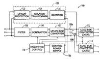
- FIG. 1is a block diagram and electrical schematic of a converter system with a pre-charge circuit according to an embodiment of the present invention.
- FIG. 2is a more detailed electrical schematic of the pre-charge circuit of FIG. 1 .
- FIG. 3is a flowchart of a method for pre-charging the DC bus of a utility connected converter system according to an embodiment of the present invention.
- a rectifier circuitis coupled to the utility power grid through an isolation transformer and circuit protection.
- the rectifier circuit outputis connected to the DC bus of the power converter to provide a pre-charging current to the DC bus capacitor(s).
- the output from the rectifier circuitalso supplies power to the control circuit power supply for the converter.
- the control circuitcloses the contactor of the converter system and activates the converter, the voltage across the DC bus capacitor(s) is increased above the level of the rectified power grid voltage provided at the output of the pre-charge circuit. This reverse-biases the rectifier circuit diodes, placing the pre-charge circuit into an inactive state.
- the internal impedance of the isolation transformerlimits the in-rush current into the DC bus capacitor(s) during the pre-charge.
- the transformerblocks the common-mode voltages inherently present on the DC bus during converter operation from being coupled to the utility grid.
- FIG. 1illustrates a converter system 100 with a pre-charge circuit 120 according to an embodiment of the present invention.
- the power converterincludes a utility-side converter 102 electrically connected to terminals a, b, and c of a utility power grid (not shown) through an electrical contactor 104 and an optional filter circuit 106 .
- Filter circuit 106is conventional and can include passive and/or active components to reduce high frequency noise, signal artifact, harmonics, and/or to improve power factor.
- the utility power gridcan provide single- or multi-phase AC electrical power, and is not limited to the three-phase power illustrated in the embodiment of FIG. 1 .
- utility-side converter 102will include supply side rectification, voltage buck or boost circuitry, and output side rectification, as is known by persons skilled in the relevant art(s).
- the rectified output of utility-side converter 102is connected to a DC bus 108 , which will usually include one or more DC bus capacitors 110 .
- One or more DC linksconnect the DC bus to the inputs of one or more load-side converters.
- the outputs of the load converter(s)can, depending on the application, supply DC or single/multiphase AC power to one or more load devices (not shown) such as a motor/generator or DC energy storage device.
- the embodiment shown in FIG. 1includes a DC-to-AC load-side converter 112 and a DC-to-DC load-side converter 114 .
- Control power supply 116includes control power output terminals that are used to supply operational power to a converter control circuit 118 for converter system 100 .
- the converter control circuitconventionally includes logic functional to operate contactor 104 as well as to activate, monitor, and control utility-side converter 102 and load-side converters 112 and 114 .
- a pre-charge circuit 120has input terminals connecting, for example, power grid terminals a and c to the input of circuit protection 122 .
- Circuit protection 122is conventional circuit protection that provides, for example, overload protection.
- the output of circuit protection 122is connected to the primary winding of an isolation transformer 124 .
- the secondary winding of isolation transformer 124is connected to the input of a rectifier 126 .
- the output of rectifier 126is connected to DC bus 108 .
- FIG. 2is a more detailed electrical schematic of pre-charge circuit 120 .
- each input conductor of pre-charge circuit 120has its own circuit protection element 202 .
- elements 202comprise a conventional multi-pole circuit breaker (e.g. a 2-pole circuit breaker having elements 202 a and 202 b ).
- elements 202are fuses.
- circuit protection 122can be any element or combination of elements that protect the circuit from overload.
- Isolation transformer 124has a turns ratio of 1-to-N. In one embodiment, isolation transformer 124 has a turns ratio of 1-to-1. In other embodiments, transformer(s) having turns ratios other than 1-to-1 are used. As would be known to persons skilled in the relevant art(s), isolation transformer 124 can be implemented using more than just one physical transformer. The impedance(s) of the transformer(s) used limit the in-rush current of pre-charge circuit 120 .
- rectifier 126is a full-wave bridge rectifier comprising four diodes 204 a , 204 b , 204 c , and 204 d .
- the present inventionis not limited however to using a full-wave bridge rectifier. Other rectifiers are used in other embodiments.
- an unrectified AC voltage from the power gridis connected to rectifier 126 of pre-charge circuit 120 through circuit protection 122 and isolation transformer 124 .
- a rectified voltageis then supplied by the output of pre-charge circuit 120 to DC bus 108 , charging DC bus capacitor(s) 110 up to a level corresponding to the output value of isolation transformer 124 .
- the output value of isolation transformer 124is dependent upon the windings ratio of isolation transformer 124 and how isolation transformer 124 is connected to the utility grid.
- Rectifier 126also provides a rectified voltage to control power supply 116 , which in turn supplies operational power to the converter control circuit (not shown) of converter system 100 .
- the in-rush current from pre-charge circuit 120 to DC bus capacitor(s) 110is primarily limited by the impedance of isolation transformer 124 .
- converter control circuit 118When converter control circuit 118 is commanded by internal or external logic to energize converter system 100 , contactor 104 is closed and utility-side converter 102 is activated.
- DC bus capacitor(s) 110are charged by utility-side converter 102 to a voltage level that exceeds the rectified voltage at the output of pre-charge circuit 120 . This reverse biases diodes 204 of rectifier 126 , thereby effectively deactivating pre-charge circuit 120 .
- the DC bus voltageis coupled by DC links to load-side converters 112 and 114 , which in turn supply operational power to load devices (not shown).
- Isolation transformer 124provides continuous galvanic isolation.
- each of the components of converter system 100 and pre-charge circuit 120must be appropriately selected and sized to meet the requirements of a particular application. Thus, specific values for the components described herein are not included. Persons skilled in the relevant art(s) will know how to determine specific values for these components for particular applications given the description herein.
- FIG. 3is a flowchart of a method 300 for supplying rectified voltage to the DC bus of a utility connected converter system using a pre-charge circuit that includes an isolation transformer and a rectifier.
- Method 300also can be used to provide rectified voltage to a control power supply of a utility connected converter system, thus eliminating the need for a separate source of power such as, for example, a battery.
- method 300comprises four steps 302 , 304 , 306 and 308 .
- Method 300can be implemented using a system embodying the present invention described herein.
- Method 300starts with step 302 .
- the isolation transformer of the pre-charge circuit of the converter systemis coupled to a utility grid.
- the transformer or transformerscan be coupled to a single phase of the utility grid or multiple phases of the utility grid in a manner that would be known to persons skilled in the relevant art(s).
- the transformer or transformershave a 1-to-1 turns ratio.
- the impedance of the transformer(s)are selected to limit the in-rush current of the pre-charge circuit.
- a rectified voltageis generated at an output of the rectifier of the pre-charge circuit.
- the output voltage of the rectifieris dependent on the type of rectifier used, the windings or turns ratio of isolation transformer(s) used, and how isolation transformer(s) are connected to the utility grid.
- the rectified voltageis generated using a full-wave bridge rectifier.
- step 306rectified voltage form the rectifier of the pre-charge circuit of the converter system is supplied to one or more capacitors coupled to the DC bus of the converter system.
- the voltageis only supplied when the contactor of the converter system is in an open position.
- the contactoris in a closed position and the utility-side converter is activated, the one or more capacitors coupled to the DC bus are charged to a voltage level higher than the rectified voltage level of the pre-charge circuit, thereby reverse biasing the diodes of the pre-charge circuit rectifier.
- the pre-charge circuitbecomes inactive.
- step 308rectified voltage form the rectifier of the pre-charge circuit of the converter system is supplied to a control power supply of the converter system.
- the voltageis only supplied when the contactor of the converter system is in the open position.
- the pre-charge circuitis inactive due to reverse biasing of the diodes of the pre-charge circuit rectifier.
- steps 306 and 308 of method 300are independent of one another. Therefore, in some method embodiments of the present invention, one of the steps 306 and 308 is omitted.
Landscapes
- Engineering & Computer Science (AREA)
- Power Engineering (AREA)
- Rectifiers (AREA)
Abstract
Description
Claims (18)
Priority Applications (1)
| Application Number | Priority Date | Filing Date | Title |
|---|---|---|---|
| US10/813,550US7092262B2 (en) | 2003-10-28 | 2004-03-31 | System and method for pre-charging the DC bus of a utility connected power converter |
Applications Claiming Priority (2)
| Application Number | Priority Date | Filing Date | Title |
|---|---|---|---|
| US51519803P | 2003-10-28 | 2003-10-28 | |
| US10/813,550US7092262B2 (en) | 2003-10-28 | 2004-03-31 | System and method for pre-charging the DC bus of a utility connected power converter |
Publications (2)
| Publication Number | Publication Date |
|---|---|
| US20050088868A1 US20050088868A1 (en) | 2005-04-28 |
| US7092262B2true US7092262B2 (en) | 2006-08-15 |
Family
ID=34527097
Family Applications (1)
| Application Number | Title | Priority Date | Filing Date |
|---|---|---|---|
| US10/813,550Expired - Fee RelatedUS7092262B2 (en) | 2003-10-28 | 2004-03-31 | System and method for pre-charging the DC bus of a utility connected power converter |
Country Status (1)
| Country | Link |
|---|---|
| US (1) | US7092262B2 (en) |
Cited By (17)
| Publication number | Priority date | Publication date | Assignee | Title |
|---|---|---|---|---|
| US20070064366A1 (en)* | 2005-08-18 | 2007-03-22 | Hammond Peter W | System and method for limiting AC inrush current |
| US20090251009A1 (en)* | 2008-04-07 | 2009-10-08 | Toshiba International Corporation | Drive Isolation Transformer Controller and Method |
| US8499874B2 (en) | 2009-05-12 | 2013-08-06 | Icr Turbine Engine Corporation | Gas turbine energy storage and conversion system |
| US8669670B2 (en) | 2010-09-03 | 2014-03-11 | Icr Turbine Engine Corporation | Gas turbine engine configurations |
| US8866334B2 (en) | 2010-03-02 | 2014-10-21 | Icr Turbine Engine Corporation | Dispatchable power from a renewable energy facility |
| US8984895B2 (en) | 2010-07-09 | 2015-03-24 | Icr Turbine Engine Corporation | Metallic ceramic spool for a gas turbine engine |
| US9042112B2 (en) | 2012-04-11 | 2015-05-26 | Delta Electronics, Inc. | Converter power unit and its bus bars |
| US9051873B2 (en) | 2011-05-20 | 2015-06-09 | Icr Turbine Engine Corporation | Ceramic-to-metal turbine shaft attachment |
| US9287783B2 (en)* | 2011-11-08 | 2016-03-15 | Fdk Corporation | Power supply device |
| US20160126858A1 (en)* | 2013-05-20 | 2016-05-05 | Ge Energy Power Conversion Technology Ltd | Input filter pre-charge fed by a medium-voltage grid supply |
| US9742185B2 (en) | 2015-04-28 | 2017-08-22 | General Electric Company | DC circuit breaker and method of use |
| US10094288B2 (en) | 2012-07-24 | 2018-10-09 | Icr Turbine Engine Corporation | Ceramic-to-metal turbine volute attachment for a gas turbine engine |
| DE102017127311A1 (en) | 2017-11-20 | 2019-05-23 | Ge Energy Power Conversion Technology Limited | Apparatus and method for biasing a power transformer in a power converter system |
| US10401885B2 (en) | 2017-08-18 | 2019-09-03 | Rolls-Royce North American Technologies Inc. | DC to DC converter output bus voltage control system |
| US10439431B2 (en) | 2016-02-23 | 2019-10-08 | Vertiv Corporation | Method to reduce inrush currents in a transformer-less rectifier uninterruptible power supply system |
| US10454276B2 (en)* | 2015-03-16 | 2019-10-22 | Abb Schweiz Ag | Power converter |
| US10833616B1 (en)* | 2019-11-22 | 2020-11-10 | Rolls-Royce Marine North America Inc. | Gas turbine engine generator power management control system |
Families Citing this family (14)
| Publication number | Priority date | Publication date | Assignee | Title |
|---|---|---|---|---|
| WO2007007812A1 (en)* | 2005-07-13 | 2007-01-18 | Mitsubishi Rayon Co., Ltd. | Prepreg |
| US7746024B2 (en)* | 2006-03-07 | 2010-06-29 | Hamilton Sundstrand Corporation | Electric engine start system with active rectifier |
| ITMI20072243A1 (en)* | 2007-11-28 | 2009-05-29 | Emerson Network Power Srl | STATIC SWITCH FOR MOTORS OF AIR CONDITIONING UNITS AND AIR CONDITIONING UNIT INCLUDING SUCH SWITCH. |
| US7965485B2 (en)* | 2009-06-12 | 2011-06-21 | Ferraz Shawmut S.A. | Circuit protection device for photovoltaic systems |
| EP2325984A1 (en)* | 2009-11-24 | 2011-05-25 | SMA Solar Technology AG | Start up of a photovoltiac field with high open circuit voltage |
| DE102010060398A1 (en)* | 2010-11-08 | 2012-05-10 | Adensis Gmbh | Method for operating a photovoltaic system for feeding electrical power into a medium-voltage network |
| US20140056041A1 (en)* | 2011-05-18 | 2014-02-27 | General Electric Company | Power generation system, power converter system, and methods of operating a power converter system |
| US10305321B2 (en) | 2016-02-10 | 2019-05-28 | Eguana Technologies | Automatic recovery control |
| US10181724B2 (en) | 2016-02-10 | 2019-01-15 | Eguana Technologies | Seamless transitions between control modes |
| US11139654B2 (en) | 2016-02-10 | 2021-10-05 | Eguana Technologies | Output control and compensation for AC coupled systems |
| DE102017204927A1 (en) | 2017-03-23 | 2018-09-27 | Siemens Aktiengesellschaft | Supply system for pre-charging a direct voltage network with electrical energy from an alternating voltage network |
| CN114079296B (en) | 2020-07-31 | 2024-04-12 | 华为数字能源技术有限公司 | Voltage conversion circuit, control method, DC/DC converter and device |
| US20240186885A1 (en)* | 2022-12-01 | 2024-06-06 | Rivian Ip Holdings, Llc | Systems and methods for energy delivery |
| DE102024202216A1 (en) | 2024-03-08 | 2025-09-11 | Robert Bosch Gesellschaft mit beschränkter Haftung | Procedure for an operation and grid module |
Citations (4)
| Publication number | Priority date | Publication date | Assignee | Title |
|---|---|---|---|---|
| US5404092A (en)* | 1993-09-03 | 1995-04-04 | Motorola, Inc. | High power factor AC-DC converter with reactive shunt regulation |
| US5631814A (en)* | 1995-06-16 | 1997-05-20 | Abraham Lavsky | Uninterruptible power supply based on non-invasive connection of backup circuit to switch power supply |
| US6275392B1 (en)* | 2000-09-27 | 2001-08-14 | Rockwell Technologies, Llc | Method and apparatus for pre-charge control of VSI |
| US6720674B1 (en)* | 2001-03-12 | 2004-04-13 | Indigo Energy, Inc. | Device for prevention of power interruptions |
- 2004
- 2004-03-31USUS10/813,550patent/US7092262B2/ennot_activeExpired - Fee Related
Patent Citations (4)
| Publication number | Priority date | Publication date | Assignee | Title |
|---|---|---|---|---|
| US5404092A (en)* | 1993-09-03 | 1995-04-04 | Motorola, Inc. | High power factor AC-DC converter with reactive shunt regulation |
| US5631814A (en)* | 1995-06-16 | 1997-05-20 | Abraham Lavsky | Uninterruptible power supply based on non-invasive connection of backup circuit to switch power supply |
| US6275392B1 (en)* | 2000-09-27 | 2001-08-14 | Rockwell Technologies, Llc | Method and apparatus for pre-charge control of VSI |
| US6720674B1 (en)* | 2001-03-12 | 2004-04-13 | Indigo Energy, Inc. | Device for prevention of power interruptions |
Cited By (24)
| Publication number | Priority date | Publication date | Assignee | Title |
|---|---|---|---|---|
| US7511975B2 (en)* | 2005-08-18 | 2009-03-31 | Siemens Energy & Automation, Inc. | System and method for limiting AC inrush current |
| US20070064366A1 (en)* | 2005-08-18 | 2007-03-22 | Hammond Peter W | System and method for limiting AC inrush current |
| US20090251009A1 (en)* | 2008-04-07 | 2009-10-08 | Toshiba International Corporation | Drive Isolation Transformer Controller and Method |
| US7880343B2 (en) | 2008-04-07 | 2011-02-01 | Toshiba International Corporation | Drive isolation transformer controller and method |
| US8499874B2 (en) | 2009-05-12 | 2013-08-06 | Icr Turbine Engine Corporation | Gas turbine energy storage and conversion system |
| US8708083B2 (en) | 2009-05-12 | 2014-04-29 | Icr Turbine Engine Corporation | Gas turbine energy storage and conversion system |
| US8866334B2 (en) | 2010-03-02 | 2014-10-21 | Icr Turbine Engine Corporation | Dispatchable power from a renewable energy facility |
| US8984895B2 (en) | 2010-07-09 | 2015-03-24 | Icr Turbine Engine Corporation | Metallic ceramic spool for a gas turbine engine |
| US8669670B2 (en) | 2010-09-03 | 2014-03-11 | Icr Turbine Engine Corporation | Gas turbine engine configurations |
| US9051873B2 (en) | 2011-05-20 | 2015-06-09 | Icr Turbine Engine Corporation | Ceramic-to-metal turbine shaft attachment |
| US9287783B2 (en)* | 2011-11-08 | 2016-03-15 | Fdk Corporation | Power supply device |
| TWI489715B (en)* | 2012-04-11 | 2015-06-21 | Delta Electronics Inc | Converter power unit and bus bar thereof |
| US9042112B2 (en) | 2012-04-11 | 2015-05-26 | Delta Electronics, Inc. | Converter power unit and its bus bars |
| US10094288B2 (en) | 2012-07-24 | 2018-10-09 | Icr Turbine Engine Corporation | Ceramic-to-metal turbine volute attachment for a gas turbine engine |
| US20160126858A1 (en)* | 2013-05-20 | 2016-05-05 | Ge Energy Power Conversion Technology Ltd | Input filter pre-charge fed by a medium-voltage grid supply |
| US9748860B2 (en)* | 2013-05-20 | 2017-08-29 | Ge Energy Power Conversion Technology Ltd | Input filter pre-charge fed by a medium-voltage grid supply |
| EP3000169B1 (en) | 2013-05-20 | 2019-07-03 | GE Energy Power Conversion Technology Ltd. | Input filter pre-charge fed by a medium-voltage grid supply |
| US10454276B2 (en)* | 2015-03-16 | 2019-10-22 | Abb Schweiz Ag | Power converter |
| US9742185B2 (en) | 2015-04-28 | 2017-08-22 | General Electric Company | DC circuit breaker and method of use |
| US10439431B2 (en) | 2016-02-23 | 2019-10-08 | Vertiv Corporation | Method to reduce inrush currents in a transformer-less rectifier uninterruptible power supply system |
| US10401885B2 (en) | 2017-08-18 | 2019-09-03 | Rolls-Royce North American Technologies Inc. | DC to DC converter output bus voltage control system |
| DE102017127311A1 (en) | 2017-11-20 | 2019-05-23 | Ge Energy Power Conversion Technology Limited | Apparatus and method for biasing a power transformer in a power converter system |
| US10554148B2 (en) | 2017-11-20 | 2020-02-04 | Ge Energy Power Conversion Technology Limited | Device and method for premagnetization of a power transformer in a converter system |
| US10833616B1 (en)* | 2019-11-22 | 2020-11-10 | Rolls-Royce Marine North America Inc. | Gas turbine engine generator power management control system |
Also Published As
| Publication number | Publication date |
|---|---|
| US20050088868A1 (en) | 2005-04-28 |
Similar Documents
| Publication | Publication Date | Title |
|---|---|---|
| US7092262B2 (en) | System and method for pre-charging the DC bus of a utility connected power converter | |
| US10554148B2 (en) | Device and method for premagnetization of a power transformer in a converter system | |
| EP2147490B1 (en) | Dynamic voltage sag correction | |
| JP4808221B2 (en) | High frequency modulation / demodulation multiphase rectifier | |
| US20050253564A1 (en) | Active power filter apparatus with reduced va rating for neutral current suppression | |
| CN111697847B (en) | Weissach rectifier assembly | |
| AU2001284979A1 (en) | High efficiency fuel cell power conditioner | |
| US6252310B1 (en) | Balanced modular power management system and method | |
| EP1078435B1 (en) | Line powered, primary side connected apparatus injecting voltage compensation into an electric power line using one transformer | |
| US20200177094A1 (en) | Pulsed rectifier architecture | |
| JP2009273355A (en) | Apparatus for transmitting electric power | |
| US7005840B2 (en) | Interface for supplying power to a load from an electrical power supply network | |
| US9236811B2 (en) | Multiphase transformer rectifier unit | |
| Cuartas et al. | Start-up, functionalities and protection issues for CHB-based solid state transformers | |
| CN210518135U (en) | Power supply device and electronic equipment | |
| EP4369584B1 (en) | Device, method, and system for resolving common-mode voltage interference | |
| JP4395669B2 (en) | Three-phase rectifier | |
| CN111987919A (en) | Power converter | |
| EP4618363A1 (en) | Active balancing of energy storage preferably at module and rack level | |
| KR100435106B1 (en) | The harmonic reduction apparatus which use the resonance of the ZERO-PHARSE-SEQUENCE IMPEDANCE | |
| JP7366076B2 (en) | Three-phase inverter and uninterruptible power supply system | |
| EP4618362A1 (en) | Active balancing of energy storage preferably at module and rack level | |
| Kumar et al. | A Novel Overvoltage Withstand Circuit with Plug-and-Play Feature for EV Chargers | |
| JPH08237944A (en) | Switching mode power supply | |
| Ohshima et al. | Development of uninterruptible secondary battery system |
Legal Events
| Date | Code | Title | Description |
|---|---|---|---|
| AS | Assignment | Owner name:CAPSTONE TURBINE CORPORATION, CALIFORNIA Free format text:ASSIGNMENT OF ASSIGNORS INTEREST;ASSIGNORS:RYAN, MICHAEL J.;GILBRETH, MARK G.;KELLER, KENNETH W.;AND OTHERS;REEL/FRAME:015836/0577;SIGNING DATES FROM 20040730 TO 20040924 | |
| AS | Assignment | Owner name:CAPSTONE TURBINE CORPORATION, CALIFORNIA Free format text:ASSIGNMENT OF ASSIGNORS INTEREST;ASSIGNORS:RYAN, MICHAEL J.;GILBRETH, MARK G.;KELLER, KENNETH W.;AND OTHERS;REEL/FRAME:016329/0668;SIGNING DATES FROM 20040730 TO 20040924 | |
| AS | Assignment | Owner name:WELLS FARGO BANK, NATIONAL ASSOCIATION, CALIFORNIA Free format text:SECURITY INTEREST;ASSIGNOR:CAPSTONE TURBINE CORPORATION, A DELAWARE CORPORATION;REEL/FRAME:022320/0030 Effective date:20090209 | |
| REMI | Maintenance fee reminder mailed | ||
| LAPS | Lapse for failure to pay maintenance fees | ||
| STCH | Information on status: patent discontinuation | Free format text:PATENT EXPIRED DUE TO NONPAYMENT OF MAINTENANCE FEES UNDER 37 CFR 1.362 | |
| FP | Lapsed due to failure to pay maintenance fee | Effective date:20100815 | |
| AS | Assignment | Owner name:CAPSTONE TURBINE CORPORATION, CALIFORNIA Free format text:RELEASE BY SECURED PARTY;ASSIGNOR:WELLS FARGO BANK, NATIONAL ASSOCIATION;REEL/FRAME:042722/0630 Effective date:20170602 | |
| AS | Assignment | Owner name:GOLDMAN SACHS SPECIALTY LENDING HOLDINGS, INC., NE Free format text:SECURITY INTEREST;ASSIGNOR:CAPSTONE TURBINE CORPORATION;REEL/FRAME:048262/0001 Effective date:20190204 | |
| AS | Assignment | Owner name:CAPSTONE GREEN ENERGY CORPORATION F/K/A CAPSTONE TURBINE CORPORATION, CALIFORNIA Free format text:RELEASE BY SECURED PARTY;ASSIGNOR:GOLDMAN SACHS SPECIALTY LENDING GROUP, L.P.;REEL/FRAME:065835/0541 Effective date:20231207 |