US7091950B2 - Force feedback device including non-rigid coupling - Google Patents
Force feedback device including non-rigid couplingDownload PDFInfo
- Publication number
- US7091950B2 US7091950B2US10/183,971US18397102AUS7091950B2US 7091950 B2US7091950 B2US 7091950B2US 18397102 AUS18397102 AUS 18397102AUS 7091950 B2US7091950 B2US 7091950B2
- Authority
- US
- United States
- Prior art keywords
- user
- actuator
- freedom
- computer
- coupled
- Prior art date
- Legal status (The legal status is an assumption and is not a legal conclusion. Google has not performed a legal analysis and makes no representation as to the accuracy of the status listed.)
- Expired - Fee Related, expires
Links
Images


Classifications
- G—PHYSICS
- G06—COMPUTING OR CALCULATING; COUNTING
- G06F—ELECTRIC DIGITAL DATA PROCESSING
- G06F3/00—Input arrangements for transferring data to be processed into a form capable of being handled by the computer; Output arrangements for transferring data from processing unit to output unit, e.g. interface arrangements
- G06F3/01—Input arrangements or combined input and output arrangements for interaction between user and computer
- G06F3/016—Input arrangements with force or tactile feedback as computer generated output to the user
- A—HUMAN NECESSITIES
- A63—SPORTS; GAMES; AMUSEMENTS
- A63F—CARD, BOARD, OR ROULETTE GAMES; INDOOR GAMES USING SMALL MOVING PLAYING BODIES; VIDEO GAMES; GAMES NOT OTHERWISE PROVIDED FOR
- A63F13/00—Video games, i.e. games using an electronically generated display having two or more dimensions
- A63F13/20—Input arrangements for video game devices
- A63F13/24—Constructional details thereof, e.g. game controllers with detachable joystick handles
- A63F13/245—Constructional details thereof, e.g. game controllers with detachable joystick handles specially adapted to a particular type of game, e.g. steering wheels
- A—HUMAN NECESSITIES
- A63—SPORTS; GAMES; AMUSEMENTS
- A63F—CARD, BOARD, OR ROULETTE GAMES; INDOOR GAMES USING SMALL MOVING PLAYING BODIES; VIDEO GAMES; GAMES NOT OTHERWISE PROVIDED FOR
- A63F13/00—Video games, i.e. games using an electronically generated display having two or more dimensions
- A63F13/25—Output arrangements for video game devices
- A63F13/28—Output arrangements for video game devices responding to control signals received from the game device for affecting ambient conditions, e.g. for vibrating players' seats, activating scent dispensers or affecting temperature or light
- A63F13/285—Generating tactile feedback signals via the game input device, e.g. force feedback
- A—HUMAN NECESSITIES
- A63—SPORTS; GAMES; AMUSEMENTS
- A63F—CARD, BOARD, OR ROULETTE GAMES; INDOOR GAMES USING SMALL MOVING PLAYING BODIES; VIDEO GAMES; GAMES NOT OTHERWISE PROVIDED FOR
- A63F13/00—Video games, i.e. games using an electronically generated display having two or more dimensions
- A63F13/80—Special adaptations for executing a specific game genre or game mode
- A63F13/803—Driving vehicles or craft, e.g. cars, airplanes, ships, robots or tanks
- G—PHYSICS
- G01—MEASURING; TESTING
- G01B—MEASURING LENGTH, THICKNESS OR SIMILAR LINEAR DIMENSIONS; MEASURING ANGLES; MEASURING AREAS; MEASURING IRREGULARITIES OF SURFACES OR CONTOURS
- G01B21/00—Measuring arrangements or details thereof, where the measuring technique is not covered by the other groups of this subclass, unspecified or not relevant
- G01B21/02—Measuring arrangements or details thereof, where the measuring technique is not covered by the other groups of this subclass, unspecified or not relevant for measuring length, width, or thickness
- G01B21/04—Measuring arrangements or details thereof, where the measuring technique is not covered by the other groups of this subclass, unspecified or not relevant for measuring length, width, or thickness by measuring coordinates of points
- G—PHYSICS
- G01—MEASURING; TESTING
- G01B—MEASURING LENGTH, THICKNESS OR SIMILAR LINEAR DIMENSIONS; MEASURING ANGLES; MEASURING AREAS; MEASURING IRREGULARITIES OF SURFACES OR CONTOURS
- G01B5/00—Measuring arrangements characterised by the use of mechanical techniques
- G01B5/004—Measuring arrangements characterised by the use of mechanical techniques for measuring coordinates of points
- G01B5/008—Measuring arrangements characterised by the use of mechanical techniques for measuring coordinates of points using coordinate measuring machines
- G—PHYSICS
- G05—CONTROLLING; REGULATING
- G05G—CONTROL DEVICES OR SYSTEMS INSOFAR AS CHARACTERISED BY MECHANICAL FEATURES ONLY
- G05G9/00—Manually-actuated control mechanisms provided with one single controlling member co-operating with two or more controlled members, e.g. selectively, simultaneously
- G05G9/02—Manually-actuated control mechanisms provided with one single controlling member co-operating with two or more controlled members, e.g. selectively, simultaneously the controlling member being movable in different independent ways, movement in each individual way actuating one controlled member only
- G05G9/04—Manually-actuated control mechanisms provided with one single controlling member co-operating with two or more controlled members, e.g. selectively, simultaneously the controlling member being movable in different independent ways, movement in each individual way actuating one controlled member only in which movement in two or more ways can occur simultaneously
- G05G9/047—Manually-actuated control mechanisms provided with one single controlling member co-operating with two or more controlled members, e.g. selectively, simultaneously the controlling member being movable in different independent ways, movement in each individual way actuating one controlled member only in which movement in two or more ways can occur simultaneously the controlling member being movable by hand about orthogonal axes, e.g. joysticks
- G—PHYSICS
- G06—COMPUTING OR CALCULATING; COUNTING
- G06F—ELECTRIC DIGITAL DATA PROCESSING
- G06F3/00—Input arrangements for transferring data to be processed into a form capable of being handled by the computer; Output arrangements for transferring data from processing unit to output unit, e.g. interface arrangements
- G06F3/01—Input arrangements or combined input and output arrangements for interaction between user and computer
- G06F3/011—Arrangements for interaction with the human body, e.g. for user immersion in virtual reality
- G—PHYSICS
- G06—COMPUTING OR CALCULATING; COUNTING
- G06F—ELECTRIC DIGITAL DATA PROCESSING
- G06F3/00—Input arrangements for transferring data to be processed into a form capable of being handled by the computer; Output arrangements for transferring data from processing unit to output unit, e.g. interface arrangements
- G06F3/01—Input arrangements or combined input and output arrangements for interaction between user and computer
- G06F3/03—Arrangements for converting the position or the displacement of a member into a coded form
- G06F3/033—Pointing devices displaced or positioned by the user, e.g. mice, trackballs, pens or joysticks; Accessories therefor
- G06F3/0346—Pointing devices displaced or positioned by the user, e.g. mice, trackballs, pens or joysticks; Accessories therefor with detection of the device orientation or free movement in a 3D space, e.g. 3D mice, 6-DOF [six degrees of freedom] pointers using gyroscopes, accelerometers or tilt-sensors
- G—PHYSICS
- G06—COMPUTING OR CALCULATING; COUNTING
- G06F—ELECTRIC DIGITAL DATA PROCESSING
- G06F3/00—Input arrangements for transferring data to be processed into a form capable of being handled by the computer; Output arrangements for transferring data from processing unit to output unit, e.g. interface arrangements
- G06F3/01—Input arrangements or combined input and output arrangements for interaction between user and computer
- G06F3/03—Arrangements for converting the position or the displacement of a member into a coded form
- G06F3/033—Pointing devices displaced or positioned by the user, e.g. mice, trackballs, pens or joysticks; Accessories therefor
- G06F3/0354—Pointing devices displaced or positioned by the user, e.g. mice, trackballs, pens or joysticks; Accessories therefor with detection of 2D relative movements between the device, or an operating part thereof, and a plane or surface, e.g. 2D mice, trackballs, pens or pucks
- G06F3/03545—Pens or stylus
- G—PHYSICS
- G06—COMPUTING OR CALCULATING; COUNTING
- G06F—ELECTRIC DIGITAL DATA PROCESSING
- G06F3/00—Input arrangements for transferring data to be processed into a form capable of being handled by the computer; Output arrangements for transferring data from processing unit to output unit, e.g. interface arrangements
- G06F3/01—Input arrangements or combined input and output arrangements for interaction between user and computer
- G06F3/03—Arrangements for converting the position or the displacement of a member into a coded form
- G06F3/033—Pointing devices displaced or positioned by the user, e.g. mice, trackballs, pens or joysticks; Accessories therefor
- G06F3/038—Control and interface arrangements therefor, e.g. drivers or device-embedded control circuitry
- G06F3/0383—Signal control means within the pointing device
- G—PHYSICS
- G09—EDUCATION; CRYPTOGRAPHY; DISPLAY; ADVERTISING; SEALS
- G09B—EDUCATIONAL OR DEMONSTRATION APPLIANCES; APPLIANCES FOR TEACHING, OR COMMUNICATING WITH, THE BLIND, DEAF OR MUTE; MODELS; PLANETARIA; GLOBES; MAPS; DIAGRAMS
- G09B23/00—Models for scientific, medical, or mathematical purposes, e.g. full-sized devices for demonstration purposes
- G09B23/28—Models for scientific, medical, or mathematical purposes, e.g. full-sized devices for demonstration purposes for medicine
- G—PHYSICS
- G09—EDUCATION; CRYPTOGRAPHY; DISPLAY; ADVERTISING; SEALS
- G09B—EDUCATIONAL OR DEMONSTRATION APPLIANCES; APPLIANCES FOR TEACHING, OR COMMUNICATING WITH, THE BLIND, DEAF OR MUTE; MODELS; PLANETARIA; GLOBES; MAPS; DIAGRAMS
- G09B9/00—Simulators for teaching or training purposes
- G09B9/02—Simulators for teaching or training purposes for teaching control of vehicles or other craft
- G09B9/08—Simulators for teaching or training purposes for teaching control of vehicles or other craft for teaching control of aircraft, e.g. Link trainer
- G09B9/28—Simulation of stick forces or the like
- A—HUMAN NECESSITIES
- A61—MEDICAL OR VETERINARY SCIENCE; HYGIENE
- A61B—DIAGNOSIS; SURGERY; IDENTIFICATION
- A61B90/00—Instruments, implements or accessories specially adapted for surgery or diagnosis and not covered by any of the groups A61B1/00 - A61B50/00, e.g. for luxation treatment or for protecting wound edges
- A61B90/50—Supports for surgical instruments, e.g. articulated arms
- A—HUMAN NECESSITIES
- A63—SPORTS; GAMES; AMUSEMENTS
- A63F—CARD, BOARD, OR ROULETTE GAMES; INDOOR GAMES USING SMALL MOVING PLAYING BODIES; VIDEO GAMES; GAMES NOT OTHERWISE PROVIDED FOR
- A63F2300/00—Features of games using an electronically generated display having two or more dimensions, e.g. on a television screen, showing representations related to the game
- A63F2300/10—Features of games using an electronically generated display having two or more dimensions, e.g. on a television screen, showing representations related to the game characterized by input arrangements for converting player-generated signals into game device control signals
- A63F2300/1037—Features of games using an electronically generated display having two or more dimensions, e.g. on a television screen, showing representations related to the game characterized by input arrangements for converting player-generated signals into game device control signals being specially adapted for converting control signals received from the game device into a haptic signal, e.g. using force feedback
- A—HUMAN NECESSITIES
- A63—SPORTS; GAMES; AMUSEMENTS
- A63F—CARD, BOARD, OR ROULETTE GAMES; INDOOR GAMES USING SMALL MOVING PLAYING BODIES; VIDEO GAMES; GAMES NOT OTHERWISE PROVIDED FOR
- A63F2300/00—Features of games using an electronically generated display having two or more dimensions, e.g. on a television screen, showing representations related to the game
- A63F2300/10—Features of games using an electronically generated display having two or more dimensions, e.g. on a television screen, showing representations related to the game characterized by input arrangements for converting player-generated signals into game device control signals
- A63F2300/1043—Features of games using an electronically generated display having two or more dimensions, e.g. on a television screen, showing representations related to the game characterized by input arrangements for converting player-generated signals into game device control signals being characterized by constructional details
- A—HUMAN NECESSITIES
- A63—SPORTS; GAMES; AMUSEMENTS
- A63F—CARD, BOARD, OR ROULETTE GAMES; INDOOR GAMES USING SMALL MOVING PLAYING BODIES; VIDEO GAMES; GAMES NOT OTHERWISE PROVIDED FOR
- A63F2300/00—Features of games using an electronically generated display having two or more dimensions, e.g. on a television screen, showing representations related to the game
- A63F2300/10—Features of games using an electronically generated display having two or more dimensions, e.g. on a television screen, showing representations related to the game characterized by input arrangements for converting player-generated signals into game device control signals
- A63F2300/1062—Features of games using an electronically generated display having two or more dimensions, e.g. on a television screen, showing representations related to the game characterized by input arrangements for converting player-generated signals into game device control signals being specially adapted to a type of game, e.g. steering wheel
- A—HUMAN NECESSITIES
- A63—SPORTS; GAMES; AMUSEMENTS
- A63F—CARD, BOARD, OR ROULETTE GAMES; INDOOR GAMES USING SMALL MOVING PLAYING BODIES; VIDEO GAMES; GAMES NOT OTHERWISE PROVIDED FOR
- A63F2300/00—Features of games using an electronically generated display having two or more dimensions, e.g. on a television screen, showing representations related to the game
- A63F2300/80—Features of games using an electronically generated display having two or more dimensions, e.g. on a television screen, showing representations related to the game specially adapted for executing a specific type of game
- A63F2300/8017—Driving on land or water; Flying
- G—PHYSICS
- G05—CONTROLLING; REGULATING
- G05G—CONTROL DEVICES OR SYSTEMS INSOFAR AS CHARACTERISED BY MECHANICAL FEATURES ONLY
- G05G9/00—Manually-actuated control mechanisms provided with one single controlling member co-operating with two or more controlled members, e.g. selectively, simultaneously
- G05G9/02—Manually-actuated control mechanisms provided with one single controlling member co-operating with two or more controlled members, e.g. selectively, simultaneously the controlling member being movable in different independent ways, movement in each individual way actuating one controlled member only
- G05G9/04—Manually-actuated control mechanisms provided with one single controlling member co-operating with two or more controlled members, e.g. selectively, simultaneously the controlling member being movable in different independent ways, movement in each individual way actuating one controlled member only in which movement in two or more ways can occur simultaneously
- G05G9/047—Manually-actuated control mechanisms provided with one single controlling member co-operating with two or more controlled members, e.g. selectively, simultaneously the controlling member being movable in different independent ways, movement in each individual way actuating one controlled member only in which movement in two or more ways can occur simultaneously the controlling member being movable by hand about orthogonal axes, e.g. joysticks
- G05G2009/0474—Manually-actuated control mechanisms provided with one single controlling member co-operating with two or more controlled members, e.g. selectively, simultaneously the controlling member being movable in different independent ways, movement in each individual way actuating one controlled member only in which movement in two or more ways can occur simultaneously the controlling member being movable by hand about orthogonal axes, e.g. joysticks characterised by means converting mechanical movement into electric signals
- G—PHYSICS
- G05—CONTROLLING; REGULATING
- G05G—CONTROL DEVICES OR SYSTEMS INSOFAR AS CHARACTERISED BY MECHANICAL FEATURES ONLY
- G05G9/00—Manually-actuated control mechanisms provided with one single controlling member co-operating with two or more controlled members, e.g. selectively, simultaneously
- G05G9/02—Manually-actuated control mechanisms provided with one single controlling member co-operating with two or more controlled members, e.g. selectively, simultaneously the controlling member being movable in different independent ways, movement in each individual way actuating one controlled member only
- G05G9/04—Manually-actuated control mechanisms provided with one single controlling member co-operating with two or more controlled members, e.g. selectively, simultaneously the controlling member being movable in different independent ways, movement in each individual way actuating one controlled member only in which movement in two or more ways can occur simultaneously
- G05G9/047—Manually-actuated control mechanisms provided with one single controlling member co-operating with two or more controlled members, e.g. selectively, simultaneously the controlling member being movable in different independent ways, movement in each individual way actuating one controlled member only in which movement in two or more ways can occur simultaneously the controlling member being movable by hand about orthogonal axes, e.g. joysticks
- G05G2009/04766—Manually-actuated control mechanisms provided with one single controlling member co-operating with two or more controlled members, e.g. selectively, simultaneously the controlling member being movable in different independent ways, movement in each individual way actuating one controlled member only in which movement in two or more ways can occur simultaneously the controlling member being movable by hand about orthogonal axes, e.g. joysticks providing feel, e.g. indexing means, means to create counterforce
- G—PHYSICS
- G05—CONTROLLING; REGULATING
- G05G—CONTROL DEVICES OR SYSTEMS INSOFAR AS CHARACTERISED BY MECHANICAL FEATURES ONLY
- G05G9/00—Manually-actuated control mechanisms provided with one single controlling member co-operating with two or more controlled members, e.g. selectively, simultaneously
- G05G9/02—Manually-actuated control mechanisms provided with one single controlling member co-operating with two or more controlled members, e.g. selectively, simultaneously the controlling member being movable in different independent ways, movement in each individual way actuating one controlled member only
- G05G9/04—Manually-actuated control mechanisms provided with one single controlling member co-operating with two or more controlled members, e.g. selectively, simultaneously the controlling member being movable in different independent ways, movement in each individual way actuating one controlled member only in which movement in two or more ways can occur simultaneously
- G05G9/047—Manually-actuated control mechanisms provided with one single controlling member co-operating with two or more controlled members, e.g. selectively, simultaneously the controlling member being movable in different independent ways, movement in each individual way actuating one controlled member only in which movement in two or more ways can occur simultaneously the controlling member being movable by hand about orthogonal axes, e.g. joysticks
- G05G9/04737—Manually-actuated control mechanisms provided with one single controlling member co-operating with two or more controlled members, e.g. selectively, simultaneously the controlling member being movable in different independent ways, movement in each individual way actuating one controlled member only in which movement in two or more ways can occur simultaneously the controlling member being movable by hand about orthogonal axes, e.g. joysticks with six degrees of freedom
- G—PHYSICS
- G06—COMPUTING OR CALCULATING; COUNTING
- G06F—ELECTRIC DIGITAL DATA PROCESSING
- G06F2203/00—Indexing scheme relating to G06F3/00 - G06F3/048
- G06F2203/01—Indexing scheme relating to G06F3/01
- G06F2203/015—Force feedback applied to a joystick
Definitions
- the present inventionrelates generally to interface devices between humans and computers, and more particularly to computer input devices that provide force feedback to the user.
- Computer systemscan be used for a variety of applications, including simulations and games which are very popular with consumers.
- a computer systemtypically displays a visual environment to a user on a display screen or other visual output device. Users can interact with the displayed environment to perform functions on the computer, such as playing a game, experience a simulation or virtual reality environment, use a computer aided design system, operate a graphical user interface (GUI), perform file manipulation, or otherwise influence events or images depicted on the screen.
- GUIgraphical user interface
- Such user interactioncan be implemented through the use of a human-computer interface device, such as a joystick, mouse, trackball, stylus, tablet, or the like, that is connected to the computer system controlling the displayed environment.
- the computerupdates the environment in response to the user's manipulation of a user-manipulatable physical object such as a joystick handle or mouse, and provides visual feedback to the user utilizing the display screen and, typically, audio speakers.
- the computersenses the user's manipulation of the object through sensors provided on the interface device.
- a usercan operate a simulated fighter aircraft or spacecraft by manipulating controls such as a joystick and other buttons and view the results of controlling the aircraft on display device portraying a virtual reality simulation or game of the aircraft in flight.
- controlssuch as a joystick and other buttons
- a usercan manipulate objects and tools in the real world, such as a stylus, and view the results of the manipulation in a virtual reality world with a “virtual stylus” viewed on a screen, in 3-D goggles, etc.
- activitiessuch as medical procedures, vehicle training, etc., virtual reality computer systems and simulations are used for training purposes to allow a user to learn from and experience a realistic “virtual” environment.
- a human interface mechanismshould also provide tactile or haptic feedback to the user, more generally known as “force feedback.”
- force feedbackThe need for the user to obtain realistic force information and experience force sensation is extensive in many kinds of simulation and greatly enhances an experience of a virtual environment or game. For example, in a simulated environment, the impact of a user controlled object against a “virtual wall” should feel as if a hard object were impacted.
- force feedbackis necessary to realistically simulate physical objects; for example, if a user touches a pen to a table, the user should feel the impact of the pen on the table.
- force feedback for controlssuch as a joystick can be desirable to realistically simulate experienced conditions, such as high acceleration in an aircraft, or the viscous, mushy feel of steering a car in mud.
- An effective human interfacenot only acts as an input device for tracking motion, but also as an output device for producing realistic force or “feel” sensations.
- Force feedback interface devicescan provide physical sensations to the user manipulating a user manipulable object of the interface device through the use of computer-controlled actuators, such as motors, provided in the interface device.
- the host computerdirectly controls forces output by controlled actuators of the interface device, i.e., a host computer closes a control loop around the system to generate sensations and maintain stability through direct host control.
- This configurationhas disadvantages in the inexpensive mass market, since the functions of reading sensor data and outputting force values to actuators can be a burden on the host computer's processor which detracts from the performance of the host in other host tasks and application execution.
- low bandwidth interfacesare often used, which reduces the ability of the host computer to control realistic forces requiring high frequency signals.
- force and texture informationis provided to a user.
- the interfaceconsists of an glove or “exoskeleton” which is worn over the user's appendages, such as fingers, arms, or body.
- Forcescan be applied to the user's appendages using tendon assemblies and actuators controlled by a computer system to simulate force and textual feedback.
- the system described by Kramerincludes a host computer directly controlling the actuators of the device, and thus has the disadvantages mentioned above.
- the Kramer deviceis not easily applicable to simulated environments where an object is referenced in virtual space and force feedback is applied to the object.
- the forces applied to the user in Kramerare with reference to the body of the user; the absolute location of the user's appendages are not easily calculated.
- the exoskeleton devices of Kramercan be complex, cumbersome or even dangerous to the user if extensive devices are worn over the user's appendages.
- Typical multi-degree-of-freedom apparatuses that include force feedbackalso include several other disadvantages. Since actuators which supply force feedback tend to be heavier and larger than sensors, they would provide inertial constraints if added to a device. There is also the problem of coupled actuators, where each actuator is coupled to a previous actuator in a chain such that a user who manipulates the object must carry the inertia of all of the subsequent actuators and links except for the first actuator in the chain. These types of interfaces also introduce tactile “noise” to the user through friction and compliance in signal transmission and limit the degree of sensitivity conveyed to the user through the actuators of the device.
- Active actuatorssuch as motors
- active actuatorstypically require high speed control signals to operate effectively and provide stability. In many situations, such high speed control signals and high power drive signals are not available or too costly, especially in the competitive, low-cost market of personal computers. Furthermore, active actuators can sometimes prove unsafe for a user when strong, unexpected forces are generated on a user of the interface who does not expect those forces.
- the present inventionprovides a human/computer interface apparatus and method which can provide multiple degrees of freedom and highly realistic force feedback to a user of the apparatus.
- the preferred apparatusincludes a local microprocessor used for enabling feel sensations including virtual walls and viscous damping in a virtual environment, thus permitting a low-cost force feedback interface device to be implemented.
- an interface device of the present inventionis used in conjunction with a host computer for monitoring user manipulations and for enabling the simulation of feel sensations in response to the user manipulations, where the feel sensations are generated in accordance with application software running on the host computer.
- the deviceincludes a user manipulatable object physically contacted by a user and movable in at least two degrees of freedom by the user and a gimbal mechanism coupled to and providing at least two degrees of freedom to the user object.
- the user objectcan be a joystick, stylus, pool cue, or other object.
- a local microprocessorseparate from the host computer system and operating simultaneously with the application software on the host, enables communication with the host computer and receives commands from the host, decodes the commands, outputs actuator signals in accordance with one or more of the commands, receives sensor signals, and reports data to the host in response to one or more of the commands.
- a communication interfaceis included for transmitting signals from the host computer to the local microprocessor and vice versa, and can be a serial communication bus such as RS232, or a wireless interface.
- Multiple actuatorsgenerate feel sensations by providing a force on the user object in at least two degrees of freedom in response to the actuator signals from the local microprocessor, and may include passive actuators such as brakes.
- At least one sensordetects the motion of the user object and reports sensor signals to the local microprocessor representative of motion of the user object.
- memoryis included locally to the local microprocessor for storing program instructions, including routines for enabling communication between the local microprocessor and the host computer, for decoding host commands, for reporting data to the host, and for generating feel sensations utilizing the actuators in accordance with software running on the host computer.
- a play mechanismsuch as a flexure is also included between actuator and user object.
- the interface deviceincludes a gimbal mechanism such as a 5-bar closed-loop linkage or a slotted bail.
- a transmission mechanismcan be included to provide mechanical advantage, and may be a capstan cable drive system including a flexible member such as a cable.
- the feel sensation generated on the useris, in one embodiment, a damping sensation simulating a feel of motion through a fluid.
- a damping constantis initialized by the local microprocessor indicating the degree of resistance experienced by the user.
- a current position of the user objectis stored by the local microprocessor, a difference between current and previous position values of the user object is determined preferably by the local microprocessor, and a sign of the difference is used as an indication of a direction of motion of the user object in one or more of the degrees of freedom.
- a variable representing force outputis determined as a function of the damping constant and the difference, a digital representation of the variable is sent by the local microprocessor to a digital to analog converter (DAC), and a resulting analog signal is output to at least one of the actuators.
- DACdigital to analog converter
- the feel sensationis a wall sensation simulating the feel of impacting a surface or obstruction.
- the wall sensationis generated at least in part preferably by the local microprocessor which tracks the position of the user object by reading said sensors.
- the host computerupdates a display of the simulation in response to user manipulation of the user object and determines that a simulated obstruction has been encountered and that such an obstruction should restrict motion of the user object in one or more directions.
- the actuatorgenerates a force to create a physical representation of said restriction of motion, thereby providing the user with a feel of hitting the simulated obstruction.
- the local microprocessoralso detects motion of the user object away from the simulated obstruction and deactivates the actuators, thereby simulating the feel of moving out of contact with the obstruction.
- the simulation on the host computermay include a cursor, where a location of the cursor on a display is updated by the host computer in response to user manipulation of the user object, and where the wall sensation is generated in response to interaction between the cursor and the obstruction.
- the interface of the present inventionenables force sensations in a virtual environment, such as hard walls and viscous damping, advantageously using a low cost interface device.
- a local microprocessorreceives commands from the host computer, decodes the commands, outputs actuator signals in accordance with the commands, receives sensor signals, and reports data to the host in response to the commands, thus relieving the host computer of substantial computational burden and allowing a slower interface between host and interface device to be used.
- Viscous dampingis enabled using the local microprocessor to compute present and previous positions of the user manipulated object to determine an amount of viscous force.
- Virtual wallsare likewise enabled by using the microprocessor to track positions of the user object to determine when wall forces are output.
- FIG. 1is a perspective view of a virtual reality system which interface a joystick with a computer system to enable feel sensations to a user of the joystick;
- FIG. 2is a schematic diagram of a mechanical apparatus for providing mechanical input and output to a computer system
- FIG. 3is a perspective front view of a preferred embodiment of the mechanical apparatus of FIG. 2 ;
- FIG. 4is a perspective rear view of the embodiment of the mechanical apparatus of FIG. 3 ;
- FIG. 5is a perspective detailed view of a capstan drive mechanism used for two degrees of motion in the present invention.
- FIG. 5 ais a side elevational view of the capstan drive mechanism shown in FIG. 5 ;
- FIG. 5 bis a detailed side view of a pulley and cable of the capstan drive mechanism of FIG. 5 ;
- FIG. 6is a perspective view of a center capstan drive mechanism for a linear axis member of the mechanical apparatus shown in FIG. 3 ;
- FIG. 6 ais a cross sectional top view of a pulley and linear axis member used in the capstan drive mechanism of FIG. 6 ;
- FIG. 6 bis a cross sectional side view of the linear axis member and transducer shown in FIG. 6 ;
- FIG. 7is a perspective view of an embodiment of the apparatus of FIG. 2 having a stylus object for the user;
- FIG. 8is a perspective view of an embodiment of the apparatus of FIG. 2 having a joystick object for the user;
- FIG. 9is a block diagram of a computer and the interface between the computer and the mechanical apparatus of FIG. 2 ;
- FIGS. 10–11are schematic diagrams of a suitable circuits for a digital to analog controller and power amplification circuit for the interface of FIG. 9 ;
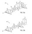
- FIG. 12 ais a schematic diagram of a transducer system in accordance with the present invention.
- FIG. 12 bis a schematic diagram of an alternate embodiment of the transducer system of FIG. 12 a;
- FIG. 13is a schematic diagram of the transducer system of FIG. 12 a which provides backlash between an actuator and an object;
- FIG. 14 ais a sectional side view of the actuator shaft and coupling of the transducer system of FIG. 13 ;
- FIG. 14 bis a sectional side view of the actuator shaft and coupling of FIG. 14 a;
- FIG. 15is a detailed view of the keyed portions of the actuator shaft and coupling of FIG. 14 a;
- FIG. 16is a schematic diagram of the system of FIG. 12 a having a flexible coupling
- FIG. 17is a schematic diagram of the transducer systems of FIGS. 12 a and 12 b coupled to the mechanical apparatus of FIG. 2 ;
- FIG. 18is a perspective view of the transducer systems of FIGS. 12 a and 12 b coupled to the mechanical apparatus of FIG. 8 ;
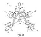
- FIG. 19is a perspective view of a slotted yoke mechanical apparatus used with the transducer system of FIG. 12 a;
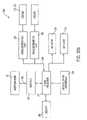
- FIG. 20 ais a block diagram showing an interface for a mechanical apparatus having the transducer system of FIG. 12 a;
- FIG. 20 bis a block diagram showing an interface having preprocessing hardware
- FIG. 21is a flow diagram illustrating a main command loop executed by the microprocessor of FIGS. 20 a and 20 b;
- FIGS. 22 a and 22 bare subroutines for use with the main command loop of FIG. 21 ;
- FIG. 23is a flow diagram illustrating a method for controlling an actuator of the transducer system of FIG. 12 a in the simulation of a fluid environment.
- FIG. 24is a flow diagram illustrating a method for controlling an actuator of the transducer system of FIG. 12 a when encountering an obstacle in a virtual environment.
- a force feedback system 10includes a human/computer interface apparatus 12 , an electronic interface 14 , and a host computer 16 .
- the illustrated system 10can used for a virtual reality simulation, video game, training procedure or simulation, use of a computer application program, or other application.
- a user manipulatable object 44is grasped by a user and manipulated. Images are displayed on a display apparatus, such as screen 20 , of the computer 16 in response to such manipulations.
- the computer 16is a preferably a personal computer or workstation, such as an IBM-PC compatible computer, Macintosh personal computer, or a SUN or Silicon Graphics workstation.
- the digital processing systemis a personal computer which operates under the WindowsTM, Unix, MacOS, or similar operating system and may include a host microprocessor such as a Pentium, PowerPC, or other type of microprocessor.
- the software running on the host computer 16may be of a wide variety. Suitable software drivers which interface simulation software with computer input/output (I/O) devices are available from Immersion Human Interface Corporation of Santa Clara, Calif. For example, in medical simulations, commercially available software such as, for example, TeleosTM from High Techsplanations of Rockville, Md. can be used.
- I/Ocomputer input/output
- the interface apparatus 12 as illustrated in FIG. 1is used to provide an interface to a video game or simulation running on host computer 16 .
- a user object 44 grasped by the user in operating the apparatus 12may be a joystick handle 28 movable in one or more degrees of freedom, as described in greater detail subsequently.
- the present inventioncan be used with any mechanical object where it is desirable to provide a human/computer interface with three to six degrees of freedom.
- Such objectsmay include joysticks, styluses, endoscopic or other similar surgical tools used in medical procedures, catheters, hypodermic needles, wires, fiber optic bundles, screw drivers, pool cues, etc.
- a mechanical apparatus 25 for interfacing mechanical input and outputis shown in phantom lines.
- Apparatus 25mechanically provides the degrees of freedom available to the user object 44 and allows sensors to sense movement in those degrees of freedom and actuators to provide forces in those degrees of freedom.
- Mechanical apparatus 25is described in greater detail below.
- the mechanical apparatusis adapted to provide data from which a computer or other computing device such as a microprocessor (see FIGS. 20 a and 20 b ) can ascertain the position and/or orientation of the user object as it moves in space. This information is then translated to an image on a computer display apparatus such as screen 20 .
- the mechanical apparatusmay be used, for example, by a user to change the position of a cursor on display screen 20 by changing the position and/or orientation of the user object 44 , the computer 16 being programmed to change the position of the cursor in proportion to the change in position and/or orientation of the user object.
- the user objectis moved through space by the user to designate to the computer how or where to move the cursor on the display apparatus. It is preferable that the mechanical apparatus provide the user object with enough degrees of freedom to enable the amount of flexibility needed to move the cursor as desired.
- the electronic interface 14is a component of the human/computer interface apparatus 12 and couples the apparatus 12 to the computer 16 . More particularly, interface 14 is used in preferred embodiments to couple the various actuators and sensors contained in apparatus 12 (which actuators and sensors are described in detail below) to computer 16 . A suitable interface 14 is described in detail with reference to FIG. 9 .
- the electronic interface 14is coupled to mechanical apparatus 25 of the apparatus 12 by a cable 30 and is coupled to the computer 16 by a cable 32 .
- signalcan be sent to and from interface 14 and computer 16 by wireless transmission and reception.
- interface 14serves solely as an input device for the computer 16 .
- interface 14serves solely as an output device for the computer 16 .
- the interface 14serves as an input/output (I/O) device for the computer 16 .
- Interface 14may be included in host computer 16 , in mechanical apparatus 12 , or be provided in separate housing as shown in FIG. 1 .
- FIG. 2a schematic diagram of mechanical apparatus 25 for providing mechanical input and output in accordance with the present invention is shown.
- Apparatus 25includes a gimbal mechanism 38 and a linear axis member 40 .
- a user object 44is preferably coupled to linear axis member 40 .
- Gimbal mechanism 38in the described embodiment, provides support for apparatus 25 on a grounded surface 56 (schematically shown as part of member 46 ).
- Gimbal mechanism 38is preferably a five-member linkage that includes a ground member 46 , extension members 48 a and 48 b , and central members 50 a and 50 b .
- Ground member 46is coupled to a base or surface which provides stability for apparatus 25 .
- Ground member 46is shown in FIG. 2 as two separate members coupled together through grounded surface 56 .
- extension member 48 ais rotatably coupled to ground member 46 and can rotate about an axis A
- central member 50 ais rotatably coupled to extension member 48 a and can rotate about a floating axis D
- extension member 48 bis rotatably coupled to ground member 46 and can rotate about axis B
- central member 50 bis rotatably coupled to extension member 48 b and can rotate about floating axis E
- central member 50 ais rotatably coupled to central member 50 b at a center point P at the intersection of axes D and E.
- the axes D and Eare “floating” in the sense that they are not fixed in one position as are axes A and B.
- Axes A and Bare substantially mutually perpendicular.
- substantially perpendicularwill mean that two objects or axis are exactly or almost perpendicular, i.e. at least within five degrees or ten degrees of perpendicular, or more preferably within less than one degree of perpendicular.
- substantially parallelwill mean that two objects or axis are exactly or almost parallel, i.e. are at least within five or ten degrees of parallel, and are preferably within less than one degree of parallel.
- Gimbal mechanism 38is formed as a five member closed chain. Each end of one member is coupled to the end of a another member.
- the five-member linkageis arranged such that extension member 48 a , central member 50 a , and central member 50 b can be rotated about axis A in a first degree of freedom.
- the linkageis also arranged such that members 48 b , 50 b , and 50 a can be rotated about axis B in a second degree of freedom.
- the angle ⁇increases or decreases with movement of object 44 into or out of the page, respectively.
- Linear axis member 40is preferably an elongated rod-like member which is coupled to central member 50 a and central member 50 b at the point of intersection P of axes A and B. As shown in FIG. 1 , linear axis member 40 can be provided as joystick handle 28 of user object 44 . In other embodiments, linear axis member 40 is coupled to a different object. Linear axis member 40 is coupled to gimbal mechanism 38 such that it extends out of the plane defined by axis A and axis B. Linear axis member 40 can be rotated about axis A by rotating extension member 48 a , central member 50 a , and central member 50 b in a first revolute degree of freedom, shown as arrow line 51 .
- Member 40can also be rotated about axis B by rotating extension member 50 b and the two central members about axis B in a second revolute degree of freedom, shown by arrow line 52 . Being also translatably coupled to the ends of central members 50 a and 50 b , linear axis member 40 can be linearly moved along floating axis C, providing a third degree of freedom as shown by arrows 53 .
- Axis Ccan, of course, be rotated about one or both axes A and B as member 40 is rotated about these axes.
- transducerssuch as sensors and actuators.
- Such transducersare preferably coupled at the link points between members of the apparatus and provide input to and output from an electrical system, such as computer 16 .
- Transducers that can be used with the present inventionare described in greater detail with respect to FIG. 2 .
- User object 44is coupled to apparatus 25 and is preferably an interface object for a user to grasp or otherwise manipulate in three dimensional (3D) space.
- One preferred user object 44is the joystick handle 28 as shown in FIG. 1 .
- Handle 28can be implemented as part of, or as the entire, linear axis member 40 .
- Other examples of user objectsare described in subsequent embodiments.
- User object 44may be moved in all three degrees of freedom provided by gimbal mechanism 38 and linear axis member 40 and additional degrees of freedom as described below. As user object 44 is moved about axis A, floating axis D varies its position, and as user object 44 is moved about axis B, floating axis E varies its position.
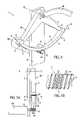
- FIGS. 3 and 4are perspective views of a specific embodiment of a mechanical apparatus 25 ′ for providing mechanical input and output to a computer system in accordance with the present invention.
- FIG. 3shows a front view of apparatus 25 ′
- FIG. 4shows a rear view of the apparatus.
- Apparatus 25 ′includes a gimbal mechanism 38 , a linear axis member 40 , and transducers 42 .
- a user object 44shown in this embodiment as a laparoscopic medical instrument having a grip portion 26 , is coupled to apparatus 25 ′.
- Apparatus 25 ′operates in substantially the same fashion as apparatus 25 described with reference to FIG. 2 .
- Gimbal mechanism 38provides support for apparatus 25 ′ on a grounded surface 56 , such as a table top or similar surface.
- the members and joints (“bearings”) of gimbal mechanism 38are preferably made of a lightweight, rigid, stiff metal, such as aluminum, but can also be made of other rigid materials such as other metals, plastic, etc.
- Gimbal mechanism 38includes a ground member 46 , capstan drive mechanisms 58 , extension members 48 a and 48 b , central drive member 50 a , and central link member 50 b .
- Ground member 46includes a base member 60 and vertical support members 62 .
- Base member 60is coupled to grounded surface 56 and provides two outer vertical surfaces 61 which are in a substantially perpendicular relation which each other.
- a vertical support member 62is coupled to each of these outer surfaces of base member 60 such that vertical members 62 are in a similar substantially 90-degree relation with each other.
- a capstan drive mechanism 58is preferably coupled to each vertical member 62 .
- Capstan drive mechanisms 58are included in gimbal mechanism 38 to provide mechanical advantage without introducing friction and backlash to the system.
- a capstan drum 59 of each capstan drive mechanismis rotatably coupled to a corresponding vertical support member 62 to form axes of rotation A and B, which correspond to axes A and B as shown in FIG. 2 .
- the capstan drive mechanisms 58are described in greater detail with respect to FIG. 5 .
- Extension member 48 ais rigidly coupled to capstan drum 59 and is rotated about axis A as capstan drum 59 is rotated.
- extension member 48 bis rigidly coupled to the other capstan drum 59 and can be rotated about axis B.
- Both extension members 48 a and 48 bare formed into a substantially 90-degree angle with a short end 49 coupled to capstan drum 59 .
- Central drive member 50 ais rotatably coupled to a long end 55 of extension member 48 a and extends at a substantially parallel relation with axis B.
- central link member 50 bis rotatably coupled to the long end of extension member 48 b and extends at a substantially parallel relation to axis A (as better viewed in FIG. 4 ).
- Central drive member 50 a and central link member 50 bare rotatably coupled to each other at the center of rotation of the gimbal mechanism, which is the point of intersection P of axes A and B.
- Bearing 64connects the two central members 50 a and 50 b together at the intersection point P.
- Gimbal mechanism 38provides two degrees of freedom to an object positioned at or coupled to the center point P of rotation.
- An object at or coupled to point Pcan be rotated about axis A and B or have a combination of rotational movement about these axes.
- Linear axis member 40is a cylindrical member that is preferably coupled to central members 50 a and 50 b at intersection point P.
- linear axis member 40can be a non-cylindrical member having a cross-section of, for example, a square or other polygon.
- Member 40is positioned through the center of bearing 64 and through holes in the central members 50 a and 50 b .
- the linear axis membercan be linearly translated along axis C, providing a third degree of freedom to user object 44 coupled to the linear axis member.
- Linear axis member 40can preferably be translated by a transducer 42 using a capstan drive mechanism similar to capstan drive mechanism 58 . The translation of linear axis member 40 is described in greater detail with respect to FIG. 6 .
- Transducers 42are preferably coupled to gimbal mechanism 38 to provide input and output signals between mechanical apparatus 25 ′ and computer 16 .
- transducers 42include two grounded transducers 66 a and 66 b , central transducer 68 , and shaft transducer 70 .
- the housing of grounded transducer 66 ais preferably coupled to vertical support member 62 and preferably includes both an actuator for providing force in or otherwise influencing the first revolute degree of freedom about axis A and a sensor for measuring the position of object 44 in or otherwise influenced by the first degree of freedom about axis A, i.e., the transducer 66 a is “associated with” or “related to” the first degree of freedom.
- a rotational shaft of actuator 66 ais coupled to a pulley of capstan drive mechanism 58 to transmit input and output along the first degree of freedom.
- the capstan drive mechanism 58is described in greater detail with respect to FIG. 5 .
- Grounded transducer 66 bpreferably corresponds to grounded transducer 66 a in function and operation.
- Transducer 66 bis coupled to the other vertical support member 62 and is an actuator/sensor which influences or is influenced by the second revolute degree of freedom about axis B.
- Grounded transducers 66 a and 66 bare preferably bi-directional transducers which include sensors and actuators.
- the sensorsare preferably relative optical encoders which provide signals to measure the angular rotation of a shaft of the transducer.
- the electrical outputs of the encodersare routed to computer interface 14 via buses 67 a and 67 b and are detailed with reference to FIG. 9 .
- Other types of sensorscan also be used, such as potentiometers, etc.
- an absolute sensoris one which the angle of the sensor is known in absolute terms, such as with an analog potentiometer.
- Relative sensorsonly provide relative angle information, and thus require some form of calibration step which provide a reference position for the relative angle information.
- the sensors described hereinare primarily relative sensors. In consequence, there is an implied calibration step after system power-up wherein the sensor's shaft is placed in a known position within the apparatus 25 ′ and a calibration signal is provided to the system to provide the reference position mentioned above. All angles provided by the sensors are thereafter relative to that reference position.
- Such calibration methodsare well known to those skilled in the art and, therefore, will not be discussed in any great detail herein.
- Transducers 66 a and 66 balso preferably include actuators which, in the described embodiment, are linear current control motors, such as DC servo motors. These motors preferably receive current signals to control the direction and torque (force output) that is produced on a shaft; the control signals for the motor are produced by computer interface 14 on control buses 67 a and 67 b and are detailed with respect to FIG. 9 .
- the motorsmay include brakes which allow the rotation of the shaft to be halted in a short span of time.
- a suitable transducer for the present invention including both an optical encoder and current controlled motoris a 20 W basket wound servo motor manufactured by Maxon of Burlingame, Calif.
- a stepper motor controlled with pulse width modulation of an applied voltageor pneumatic motors.
- the present inventionis much more suited to the use of linear current controlled motors. This is because voltage pulse width modulation or stepper motor control involves the use of steps or pulses which can be felt as “noise” by the user. Such noise corrupts the virtual simulation. Linear current control is smoother and thus more appropriate for the present invention.
- Passive actuatorscan also be used in transducers 66 a , 66 b and 68 .
- Magnetic particle brakes or friction brakescan be used in addition to or instead of a motor to generate a passive resistance or friction in a degree of motion.
- An alternate preferred embodiment only including passive actuatorsmay not be as realistic as an embodiment including motors; however, the passive actuators are typically safer for a user since the user does not have to fight generated forces.
- transducers 42can include only sensors to provide an apparatus without force feedback along designated degrees of freedom. Similarly, all or some of transducers 42 can be implemented as actuators without sensors to provide only force feedback.
- Central transducer 68is coupled to central drive member 50 a and preferably includes an actuator for providing force in the linear third degree of freedom along axis C and a sensor for measuring the position of object 44 along the third degree of freedom.
- the rotational shaft of central transducer 68is coupled to a translation interface coupled to central drive member 50 a which is described in greater detail with respect to FIG. 6 .
- central transducer 68is an optical encoder and DC servo motor combination similar to the actuators 66 a and 66 b described above.
- the transducers 66 a , 66 b and 68 of the described embodimentare advantageously positioned to provide a very low amount of inertia to the user handling object 44 .
- Transducer 66 a and transducer 66 bare decoupled, meaning that the transducers are both directly coupled to ground member 46 which is coupled to ground surface 56 , i.e. the ground surface carries the weight of the transducers, not the user handling object 44 .
- the weights and inertia of the transducers 66 a and 66 bare thus substantially negligible to a user handling and moving object 44 .
- Apparatus 25 ′is a high bandwidth force feedback system, meaning that high frequency signals can be used to control transducers 42 and these high frequency signals will be applied to the user object with high precision, accuracy, and dependability. The user feels very little compliance or “mushiness” when handling object 44 due to the high bandwidth.
- one actuator“rides” upon another actuator in a serial chain of links and actuators. This low bandwidth arrangement causes the user to feel the inertia of coupled actuators when manipulating an object.
- Central transducer 68is positioned near the center of rotation of two revolute degrees of freedom. Though the transducer 68 is not grounded, its central position permits a minimal inertial contribution to the mechanical apparatus 25 ′ along the provided degrees of freedom. A user manipulating object 44 thus will feel minimal internal effects from the weight of transducers 66 a , 66 b and 68 .
- Shaft transducer 70preferably includes a sensor and is provided in the described embodiment to measure a fourth degree of freedom for object 44 .
- Shaft transducer 70is preferably positioned at the end of linear axis member 40 that is opposite to the object 44 and measures the rotational position of object 44 about axis C in the fourth degree of freedom, as indicated by arrow 72 .
- Shaft transducer 70is described in greater detail with respect to FIGS. 6 and 6 b .
- shaft transducer 72is implemented using an optical encoder similar to the encoders described above.
- a suitable input transducer for use in the present inventionis an optical encoder model SI marketed by U.S. Digital of Vancouver, Wash.
- shaft transducer 70only includes a sensor and not an actuator.
- an actuatorsuch as a motor can be included in shaft transducer 70 similar to transducers 66 a , 66 b , and 68 .
- Object 44is shown in FIGS. 3 and 4 as a grip portion 26 of a laparoscopic tool.
- a shaft portion 27is implemented as linear axis member 40 .
- a usercan move the laparoscopic tool about axes A and B, and can translate the tool along axis C and rotate the tool about axis C. The movements in these four degrees of freedom will be sensed and tracked by computer system 16 . Forces can be applied preferably in the first three degrees of freedom by the computer system to simulate the tool impacting a portion of subject body, experiencing resistance moving through tissues, etc.
- additional transducerscan be added to apparatus 25 ′ to provide additional degrees of freedom for object 44 .
- a transducercan be added to grip 26 of laparoscopic tool 18 to sense when the user moves the two portions 26 a and 26 b relative to each other to simulate extending the cutting blade of the tool.
- Such a laparoscopic tool sensoris described in U.S. patent application Ser. No. 08/275,120, filed Jul. 14, 1994 and entitled “Method and Apparatus for Providing Mechanical I/O for Computer Systems” assigned to the assignee of the present invention and incorporated herein by reference in its entirety.
- FIG. 5is a perspective view of a capstan drive mechanism 58 shown in some detail.
- the drive mechanism 58 coupled to extension arm 48 bis shown; the other capstan drive 58 coupled to extension arm 48 a is substantially similar to the mechanism presented here.
- Capstan drive mechanism 58includes capstan drum 59 , capstan pulley 76 , and stop 78 .
- Capstan drum 59is preferably a wedge-shaped member having leg portion 82 and a curved portion 84 . Other shapes of member 59 can also be used.
- Leg portion 82is pivotally coupled to vertical support member 62 at axis B (or axis A for the opposing capstan drive mechanism).
- Extension member 48 bis rigidly coupled to leg portion 82 such that when capstan drum 59 is rotated about axis B, extension member 48 b is also rotated and maintains the position relative to leg portion 82 as shown in FIG. 5 .
- Curved portion 84couples the two ends of leg portion 82 together and is preferably formed in an arc centered about axis B. Curved portion 84 is preferably positioned such that its bottom edge 86 is about 0.030 inches above pulley 76 .
- Cable 80is preferably a thin metal cable connected to curved portion 84 of the capstan drum. Other types of durable cables, cords, wire, etc. can be used as well. Cable 80 is attached at a first end to curved portion 84 near an end of leg portion 82 and is drawn tautly against the outer surface 86 of curved portion 84 . Cable 80 is wrapped around pulley 76 a number of times and is then again drawn tautly against outer surface 86 . The second end of cable 80 is firmly attached to the other end of curved portion 84 near the opposite leg of leg portion 82 . The cable transmits rotational force from pulley 76 to the capstan drum 59 , causing capstan drum 59 to rotate about axis B as explained below.
- the cablealso transmits rotational force from drum 59 to the pulley and transducer 66 b .
- the tension in cable 80should be at a level so that negligible backlash or play occurs between capstan drum 59 and pulley 76 .
- the tension of cable 80can be adjusted by pulling more (or less) cable length through an end of curved portion 84 .
- Caps 81 on the ends of curved portion 84can be used to easily tighten cable 80 .
- Each cap 81is preferably tightly coupled to cable 80 and includes a pivot and tightening screw which allow the cap to move in a direction indicated by arrow 83 to tighten cable 80 .
- Capstan pulley 76is a threaded metal cylinder which transfers rotational force from transducer 66 b to capstan drum 59 and from capstan drum 59 to transducer 66 b .
- Pulley 76is rotationally coupled to vertical support member 62 by a shaft 88 (shown in FIG. 5 a ) positioned through a bore of vertical member 62 and rigidly attached to pulley 76 .
- Transducer 66 bis coupled to pulley 76 by shaft 88 through vertical support member 62 . Rotational force is applied from transducer 66 b to pulley 76 when the actuator of transducer 66 b rotates the shaft.
- the pulleytransmits the rotational force to cable 80 and thus forces capstan drum 59 to rotate in a direction about axis B.
- Extension member 48 brotates with capstan drum 59 , thus causing force along the second degree of freedom for object 44 .
- pulley 76 , capstan drum 59 and extension member 48 bwill only actually rotate if the user is not applying the same amount or a greater amount of rotational force to object 44 in the opposite direction to cancel the rotational movement. In any event, the user will feel the rotational force along the second degree of freedom in object 44 as force feedback.
- the capstan mechanism 58provides a mechanical advantage to apparatus 25 ′ so that the force output of the actuators can be increased.
- the ratio of the diameter of pulley 76 to the diameter of capstan drum 59dictates the amount of mechanical advantage, similar to a gear system. In the preferred embodiment, the ratio of drum to pulley is equal to 15:1, although other ratios can be used in other embodiments.
- extension member 48 brotates about axis B and rotates capstan drum 59 about axis B as well.
- This movementcauses cable 80 to move, which transmits the rotational force to pulley 76 .
- Pulley 76rotates and causes shaft 88 to rotate, and the direction and magnitude of the movement is detected by the sensor of transducer 66 b .
- a similar processoccurs along the first degree of freedom for the other capstan drive mechanism 58 .
- the capstan drive mechanismprovides a mechanical advantage to amplify the sensor resolution by a ratio of drum 59 to pulley 76 (15:1 in the preferred embodiment).
- Stop 78is rigidly coupled to vertical support member 62 a few millimeters above curved portion 84 of capstan drum 59 . Stop 78 is used to prevent capstan drum 59 from moving beyond a designated angular limit. Thus, drum 59 is constrained to movement within a range defined by the arc length between the ends of leg portion 82 . This constrained movement, in turn, constrains the movement of object 44 in the first two degrees of freedom.
- stop 78is a cylindrical member inserted into a threaded bore in vertical support member 62 .
- FIG. 5 ais a side elevational view of capstan mechanism 58 as shown in FIG. 5 .
- Cable 80is shown routed along the bottom side 86 of curved portion 84 of capstan drum 59 .
- Cable 80is preferably wrapped around pulley 76 so that the cable is positioned between threads 90 , i.e., the cable is guided by the threads as shown in greater detail in FIG. 5 b .
- the portion of cable 80 wrapped around the pulleytravels closer to or further from vertical support member 62 , depending on the direction that pulley 76 rotates. For example, if pulley 76 is rotated counterclockwise (when viewing the pulley as in FIG. 5 ), then cable 80 moves toward vertical support member 62 as shown by arrow 92 .
- Capstan drum 59also rotates clockwise as shown by arrow 94 .
- the threads of pulley 76are used mainly to provide cable 80 with a better grip on pulley 76 .
- pulley 76includes no threads, and the high tension in cable 80 allows cable 80 to grip pulley 76 .
- Capstan drive mechanism 58is advantageously used in the present invention to provide transmission of forces and mechanical advantage between transducers 66 a and 66 b and object 44 without introducing substantial compliance, friction, or backlash to the system.
- a capstan driveprovides increased stiffness, so that forces are transmitted with negligible stretch and compression of the components. The amount of friction is also reduced with a capstan drive mechanism so that substantially “noiseless” tactile signals can be provided to the user.
- the amount of backlash contributed by a capstan driveis also negligible. “Backlash” is the amount of play that occurs between two coupled rotating objects in a gear or pulley system.
- gears, belts, or other types of drive mechanismscould also be used in place of capstan drive mechanism 58 in alternate embodiments to transmit forces between transducer 66 a and extension member 48 b .
- gears and the liketypically introduce some backlash in the system.
- a usermight be able to feel the interlocking and grinding of gear teeth during rotation of gears when manipulating object 44 ; the rotation in a capstan drive mechanism is much less noticeable.
- FIG. 6is a perspective view of central drive member 50 a and linear axis member 40 shown in some detail.
- Central drive member 50 ais shown in a partial cutaway view to expose the interior of member 50 a .
- Central transducer 68is coupled to one side of central drive member 50 a .
- a capstan drive mechanismis used to transmit forces between transducer 68 and linear axis member 40 along the third degree of freedom.
- a rotatable shaft 98 of transducer 68extends through a bore in the side wall of central drive member 50 a and is coupled to a capstan pulley 100 . Pulley 100 is described in greater detail below with respect to FIG. 6 a.
- Linear axis member 40preferably includes an exterior sleeve 91 and an interior shaft 93 (described with reference to FIG. 6 b , below).
- Exterior sleeve 91is preferably a partially cylindrical member having a flat 41 provided along its length. Flat 41 prevents sleeve 91 from rotating about axis C in the fourth degree of freedom described above.
- Linear axis member 40is provided with a cable 99 which is secured on each end of member 40 by tension caps 101 . Cable 99 preferably runs down a majority of the length of exterior sleeve 91 on the surface of flat 41 and can be tightened, for example, by releasing a screw 97 , pulling an end of cable 99 until the desired tension is achieved, and tightening screw 97 . Similarly to the cable of the capstan mechanism described with reference to FIG. 5 , cable 99 should have a relatively high tension.
- Pulley 100preferably includes a central axle portion 103 and end lip portions 105 .
- Exterior sleeve 91is preferably positioned such that flat 41 of the sleeve is touching or is very close to lip portions 105 on both sides of axle portion 103 .
- the cable 99 portion around pulley 100is wrapped around central axle portion 103 and moves along portion 103 towards and away from shaft 98 as the pulley is rotated clockwise and counterclockwise, respectively.
- axle portion 103is smaller than lip portion 105 , providing space between the pulley 100 and flat 41 where cable 99 is attached and allowing free movement of the cable.
- Pulley 100preferably does not include threads, unlike pulley 76 , since the tension in cable 99 allows the cable to grip pulley 100 tightly.
- pulley 100can be a threaded or unthreaded cylinder similar to capstan pulley 76 described with reference to FIG. 5 .
- transducer 68can translate linear axis member 40 along axis C when the pulley is rotated by the actuator of transducer 68 .
- linear axis member 40is translated along axis C by the user manipulating object 44 , pulley 100 and shaft 98 are rotated; this rotation is detected by the sensor of transducer 68 .
- the capstan drive mechanismprovides low friction and smooth, rigid operation for precise movement of linear axis member 40 and accurate position measurement of the member 40 .
- a drive wheelmade of a rubber-like material or other frictional material can be positioned on shaft 98 to contact linear axis member 40 along the edge of the wheel. The wheel can cause forces along member 40 from the friction between wheel and linear axis member.
- a drive wheel mechanismis disclosed in the abovementioned application Ser. No. 08/275,120 as well as in U.S. patent application Ser. No. 08/344,148, filed Nov.
- Linear axis member 40can also be a single shaft in alternate embodiments instead of a dual part sleeve and shaft.
- interior shaft 93is positioned inside hollow exterior sleeve 91 and is rotatably coupled to sleeve 91 .
- a first end 107 of shaft 93preferably extends beyond sleeve 91 and is coupled to object 44 .
- shaft 93is also rotated about axis C in the fourth degree of freedom within sleeve 91 .
- Shaft 93is translated along axis C in the third degree of freedom when sleeve 91 is translated.
- interior shaft 93can be coupled to a shaft of object 44 within exterior sleeve 91 .
- shaft 27 of laparoscopic tool 18can extend into sleeve 91 and be coupled to shaft 93 within the sleeve, or shaft 27 can extend all the way to transducer 70 and functionally be used as shaft 93 .
- Shaft 93is coupled at its second end 109 to transducer 70 , which, in the preferred embodiment, is an optical encoder sensor.
- the housing 111 of transducer 70is rigidly coupled to exterior sleeve 91 by a cap 115 , and a shaft 113 of transducer 70 is coupled to interior shaft 93 so that transducer 70 can measure the rotational position of shaft 93 and object 44 .
- an actuatorcan also be included in transducer 70 to provide rotational forces about axis C to shaft 93 .
- FIG. 7is a perspective view of an alternate embodiment of the mechanical apparatus 25 ′′ and user object 44 of the present invention.
- Mechanical apparatus 25 ′′ shown in FIG. 7operates substantially the same as apparatus 25 ′ shown in FIGS. 3 and 4 .
- User object 44is a stylus 102 which the user can grasp and move in six degrees of freedom.
- Stylus 102can be sensed and force can be applied in various degrees of freedom by a computer system and interface such as computer 16 and interface 14 of FIG. 1 .
- Stylus 102can be used in virtual reality simulations in which the user can move the stylus in 3D space to point to objects, write words, drawings, or other images, etc.
- a usercan view a virtual environment generated on a computer screen or in 3D goggles.
- a virtual styluscan be presented in a virtual hand of the user.
- the computer systemtracks the position of the stylus with sensors as the user moves it.
- the computer systemalso provides force feedback to the stylus when the user moves the stylus against a virtual desk top, writes on a virtual pad of paper, etc. It thus appears and feels to the user that the stylus is contacting a real surface.
- Stylus 102preferably is coupled to a floating gimbal mechanism 104 which provides two degrees of freedom in addition to the four degrees of freedom provided by apparatus 25 ′ described with reference to FIGS. 3 and 4 .
- Floating gimbal mechanism 104includes a U-shaped member 106 which is rotatably coupled to an axis member 108 by a shaft 109 so that U-shaped member 106 can rotate about axis F.
- Axis member 108is rigidly coupled to linear axis member 40 .
- the housing of a transducer 110is coupled to U-shaped member 106 and a shaft of transducer 110 is coupled to shaft 109 .
- Transducer 110is preferably a sensor, such as an optical encoder as described above with reference to transducer 70 , which measures the rotation of U-shaped member 106 about axis F in a fifth degree of freedom and provides electrical signals indicating such movement to interface 14 .
- Stylus 102is preferably rotatably coupled to U-shaped member 106 by a shaft (not shown) extending through the U-shaped member. This shaft is coupled to a shaft of transducer 112 , the housing of which is coupled to U-shaped member 106 as shown.
- Transducer 112is preferably a sensor, such as an optical encoder as described above, which measures the rotation of stylus 102 about the lengthwise axis G of the stylus in a sixth degree of freedom.
- actuatorsare preferably not included for the fourth, fifth, and sixth degrees of freedom in the described embodiment, since actuators are typically heavier than sensors and, when positioned at the locations of transducers 70 , 100 , and 112 , would create more inertia in the system.
- the force feedback for the designated three degrees of freedomallows impacts and resistance to be simulated, which is typically adequate in many virtual reality applications. Force feedback in the fourth, fifth, and sixth degrees of freedom would allow torques on stylus 102 to be simulated as well, which may or may not be useful in a simulation.
- FIG. 8is a perspective view of a second alternate embodiment of the mechanical apparatus 25 ′′′ and user object 44 of the present invention.
- Mechanical apparatus 25 ′′′ shown in FIG. 8operates substantially the same as apparatus 25 ′ shown in FIGS. 3 and 4 .
- User object 44is a joystick 112 which the user can preferably move in two degrees of freedom, similar to the joystick 28 shown in FIG. 1 .
- Joystick 112can be sensed and force can be applied in both degrees of freedom by a computer system and interface similar to computer 16 and interface 14 of FIG. 1 .
- joystick 112is coupled to cylindrical fastener 64 so that the user can move the joystick in the two degrees of freedom provided by gimbal mechanism 38 as described above.
- Linear axis member 40is not typically included in the embodiment of FIG. 8 , since a joystick is not usually translated along an axis C.
- joystick 112can be coupled to linear axis member 40 similarly to stylus 102 as shown in FIG. 7 to provide a third degree of freedom.
- linear axis member 40can rotate about axis C and transducer 70 can be coupled to apparatus 25 ′′′ to provide a fourth degree of freedom.
- a floating gimbal mechanism as shown in FIG. 7or a different mechanism, can be added to the joystick to allow a full six degrees of freedom.
- Joystick 112can be used in virtual reality simulations in which the user can move the joystick to move a vehicle, point to objects, control a mechanism, etc.
- a usercan view a virtual environment generated on a computer screen or in 3D goggles in which joystick 112 controls an aircraft.
- the computer systemtracks the position of the joystick as the user moves it around with sensors and updates the virtual reality display accordingly to make the aircraft move in the indicated direction, etc.
- the computer systemalso provides force feedback to the joystick, for example, when the aircraft is banking or accelerating in a turn or in other situations where the user may experience forces on the joystick or find it more difficult to steer the aircraft.
- FIG. 9is a block diagram of a computer 16 and an interface circuit 120 used in interface 14 to send and receive signals from mechanical apparatus 25 .
- Circuit 120includes computer 16 , interface card 120 , DAC 122 , power amplifier circuit 124 , digital sensors 128 , and sensor interface 130 .
- analog sensors 132instead of or in addition to digital sensors 128 , and ADC 134 .
- the interface 14 between computer 16 and mechanical apparatus 25 as shown in FIG. 1can be considered functionally equivalent to the interface circuits enclosed within the dashed line in FIG. 14 .
- Other types of interfaces 14can also be used.
- an electronic interface 14is described in U.S. patent application Ser. No. 08/092,974, filed Jul.
- Interface card 120is preferably a card which can fit into an interface slot of computer 16 .
- interface card 14can be implemented as an ISA or other well-known standard interface card which plugs into the motherboard of the computer and provides input and output ports connected to the main data bus of the computer.
- Digital to analog converter (DAC) 122is coupled to interface card 120 and receives a digital signal from computer 16 .
- DAC 122converts the digital signal to analog voltages which are then sent to power amplifier circuit 124 .
- a DAC circuit suitable for use with the present inventionis well known to those skilled in the art; one example is shown in FIG. 10 .
- Power amplifier circuit 124receives an analog low-power control voltage from DAC 122 and amplifies the voltage to control actuators 126 .
- Power amplifier circuits 124are also well known to those skilled in the art; one example is shown in FIG. 11 .
- Actuators 126are preferably DC servo motors incorporated into the transducers 66 a , 66 b , and 68 , and any additional actuators, as described with reference to the embodiments shown in FIGS. 3 , 7 , and 8 for providing force feedback to a user manipulating object 44 coupled to mechanical apparatus 25 .
- Digital sensors 128provide signals to computer 16 relating the position of the user object 44 in 3D space.
- sensors 128are relative optical encoders, which are electro-optical devices that respond to a shaft's rotation by producing two phase-related signals.
- sensor interface circuit 130which is preferably a single chip, receives the signals from digital sensors 128 and converts the two signals from each sensor into another pair of clock signals, which drive a bi-directional binary counter. The output of the binary counter is received by computer 16 as a binary number representing the angular position of the encoded shaft.
- Such circuits, or equivalent circuitsare well known to those skilled in the art; for example, the Quadrature Chip from Hewlett Packard, California performs the functions described above.
- Analog sensors 132can be included instead of digital sensors 128 for all or some of the transducers of the present invention.
- a strain gaugecan be connected to stylus 130 of FIG. 7 to measure forces.
- Analog sensors 132provide an analog signal representative of the position of the user object in a particular degree of motion.
- Analog to digital converter (ADC) 134converts the analog signal to a digital signal that is received and interpreted by computer 16 , as is well known to those skilled in the art.
- ADCanalog to digital converter
- FIG. 10is a schematic view of a DAC circuit 122 of FIG. 9 suitable for converting an input digital signal to an analog voltage that is output to power amplifier circuit 124 .
- circuit 122includes a parallel DAC 136 , such as the DAC1220 manufactured by National Semiconductor, which is designed to operate with an external generic op amp 138 .
- Op amp 138for example, outputs a signal from zero to ⁇ 5 volts proportional to the binary number at its input.
- Op amp 140is an inverting summing amplifier that converts the output voltage to a symmetrical bipolar range.
- Op amp 140produces an output signal between ⁇ 2.5 V and +2.5 V by inverting the output of op amp 138 and subtracting 2.5 volts from that output; this output signal is suitable for power amplification in amplification circuit 124 .
- circuit 122is intended as one example of many possible circuits that can be used to convert a digital signal to a desired analog signal.
- FIG. 11is a schematic view of a power amplifier circuit 124 suitable for use in the interface circuit 14 shown in FIG. 9 .
- Power amplifier circuitreceives a low power control voltage from DAC circuit 122 to control high-power, current-controlled servo motor 126 .
- the input control voltagecontrols a transconductance stage composed of amplifier 142 and several resistors.
- the transconductance stageproduces an output current proportional to the input voltage to drive motor 126 while drawing very little current from the input voltage source.
- the second amplifier stageincluding amplifier 144 , resistors, and a capacitor C, provides additional current capacity by enhancing the voltage swing of the second terminal 147 of motor 146 .
- circuit 124is intended as one example of many possible circuits that can be used to amplify voltages to drive actuators 126 .
- FIG. 12 ais a schematic diagram of a transducer system 200 suitable for use with the present invention.
- Transducer system 200is ideally suited for an interface system in which passive actuators, instead of active actuators, are implemented. As shown in FIG. 12 a , transducer system 200 is applied to a mechanism having one degree of freedom, as shown by arrows 201 . Embodiments in which system 200 is applied to systems having additional degrees of freedom are described subsequently.
- Transducer system 200includes an actuator 202 , an actuator shaft 204 , a non-rigidly attached coupling 206 , a coupling shaft 208 , a sensor 210 , and an object 44 .
- Actuator 202transmits a force to object 44 and is preferably grounded, as shown by symbol 203 .
- Actuator 202is rigidly coupled to an actuator shaft 204 which extends from actuator 202 to non-rigidly attached coupling 206 .
- Actuator 202provides rotational forces, shown by arrows 212 , on actuator shaft 204 .
- actuator 202is a passive actuator which can apply a resistive or frictional force (i.e., drag) to shaft 204 in the directions of arrow 212 but cannot provide an active force to shaft 204 (i.e., actuator 202 cannot cause shaft 204 to rotate).
- an external rotational forcesuch as a force generated by a user
- passive actuator 202provides resistive forces to that external rotational force.
- Preferred passive actuatorsinclude rotary magnetic brakes, and, in particular, magnetic particle brakes, which are low cost and power-efficient devices. Suitable magnetic particle brakes can be obtained from Force Limited, Inc. of Santa Monica, Calif.
- Passive actuatorscan provide realistic force feedback to a user operating an interface apparatus in a simulated environment. Passive actuators impose a resistance to the motion of an object 44 manipulated by the user. Thus, a user who manipulates an interface having passive actuators will feel forces only when he or she actually moves an object of the interface.
- Passive actuators 202provide several advantages when compared to active actuators.
- a substantially lower currentis required to drive passive actuators than active actuators. This allows a less expensive power supply to drive a passive actuator system, and also allows a force feedback mechanism to be smaller and more lightweight due to the smaller power supply.
- passive actuatorsrequire substantially slower control signals to operate effectively in a simulation environment than do active actuators such as motors. This is significant if the controller of an interface mechanism is a computer system that includes only a standard, low-speed input/output port, such as a serial port. Serial ports are quite common to personal computers but do not communicate quickly enough to perform real-time, stable control of most active actuators. When using a controller with slower control signals, passive actuators can provide stable force feedback to the user.
- Another advantage of passive actuatorsis that passive actuators do not generate forces on the interface and the user and are thus more safe for the user.
- Coupling 206is coupled to actuator shaft 204 .
- Actuator 202 , actuator shaft 204 , and coupling 206can be considered to be an “actuator assembly” or, in a passive actuating system, a “braking mechanism.”
- Coupling 206is preferably not rigidly coupled to actuator shaft 204 and thus allows an amount (magnitude) of “play” between actuator shaft 204 and coupling 206 .
- the usercan move the object a short distance without fighting the drag induced by a passive actuator such as a brake.
- actuator 202can apply a resistive or frictional force to actuator shaft 204 so that actuator shaft 204 is locked in place, even when force is applied to the shaft.
- Coupling 206can still be freely rotated by an additional distance in either rotational direction due to the play between coupling 206 and shaft 204 . This play is intentional for purposes that will be described below, and is thus referred to as a “desired” amount of play.
- coupling 206Once coupling 206 is rotated to the limit of the allowed play, it either forces shaft 204 to rotate with it further; or, if actuator 202 is holding (i.e., locking) shaft 204 , the coupling cannot be further rotated in that rotational direction.
- the amount of desired play between actuator 202 and object 44greatly depends on the resolution of the sensor 210 being used, and is described in greater detail below. Examples of types of play include rotary backlash, such as occurs in gear systems as described in the above embodiments, and compliance or torsion flex, which can occur with flexible, rotational and non-rotational members. Embodiments including these forms of play are described in greater detail below with reference to FIGS. 13 and 16 , respectively.
- Coupling shaft 208is rigidly coupled to coupling 206 and extends to sensor 210 .
- Sensor 210is preferably rigidly coupled to coupling shaft 208 so as to detect rotational movement of shaft 208 and object 44 about axis H.
- Sensor 210preferably provides a electrical signal indicating the rotational position of shaft 208 and is preferably grounded as indicated by symbol 211 .
- sensor 210is a digital optical encoder, similar to the encoders described in the above embodiments of FIGS. 1–11 . In alternate embodiments, sensor 210 can be separated from object 44 , coupling shaft 208 , and coupling 206 .
- a sensor having an emitter and detector of electromagnetic energymight be disconnected from the rest of transducer system 200 yet be able to detect the rotational position of object 44 using a beam of electromagnetic energy, such as infrared light.
- a magnetic sensorcould detect the position of object 44 while being uncoupled to shaft 208 or object 44 . The operation of such sensors are well-known to those skilled in the art.
- Sensor 210has a sensing resolution, which is the smallest change in rotational position of coupling shaft 208 that the sensor can detect.
- a sensing resolutionis the smallest change in rotational position of coupling shaft 208 that the sensor can detect.
- an optical encoder of the described embodimentmay be able to detect on the order of about 3600 equally-spaced “pulses” (described below) per revolution of shaft 208 , which is about 10 detected pulses per degree of rotational movement.
- the sensing resolution of this sensoris about 1/10 degree in this example. Since it is desired to detect the desired play between actuator 202 and object 44 (as described below), this desired play should not be less than the sensing resolution of sensor 210 (e.g., 1/10 degree). Preferably, the desired play between actuator and object would be at least 1 ⁇ 5 degree in this example, since the encoder could then detect two pulses of movement, which would provide a more reliable measurement and allow the direction of the movement to be more easily determined.
- Sensor 210should also be as rigidly coupled to shaft 208 as possible so that the sensor can detect the desired play of shaft 208 and object 44 . Any play between sensor 210 and object 44 should be minimized so that such play does not adversely affect the sensor's measurements. Typically, any inherent play between sensor 210 and object 44 should be less than the sensing resolution of the sensor, and preferably at least an order of magnitude less than the sensing resolution. Thus, in the example above, the play between sensor and object should be less than 1/10 degree and preferably less than 1/100 degree. Use of steel or other rigid materials for shaft 208 and other components, which is preferred, can allow the play between sensor 210 and object 44 to be made practically negligible for purposes of the present invention.
- a sensor that is “rigidly” coupled to a memberhas a play less than the sensing resolution of the sensor (preferably a negligible amount).
- the play between actuator 202 and object 44is described in greater detail below.
- a suitable encoder to be used for sensor 210is the “Softpot” from U.S. Digital of Vacouver, Wash.
- Object 44is rigidly coupled to coupling shaft 208 .
- Object 44can take a variety of forms, as described in previous embodiments, and can be directly coupled to coupling shaft 208 or can be coupled through other intermediate members to shaft 208 .
- object 44is coupled to shaft 208 between coupling 206 and sensor 210 .
- shaft 208is also rotated about axis H and sensor 210 detects the magnitude and direction of the rotation of object 44 .
- object 44can be coupled directly to coupling 206 .
- Coupling 206 and/or shafts 204 and 208can be considered a “play mechanism” for providing the desired play between actuator 202 and object 44 .
- Certain suitable objects 44include a joystick, medical instrument (catheter, laparoscope, etc.), a steering wheel (e.g. having one degree of freedom), a pool cue, etc.
- transducer system 200is ideally suited for mechanical systems that include low-cost elements such as passive actuators. If a controlling computer system, such as computer system 16 , is to provide accurate force feedback to an object being held and moved by a user, the computer system should be able to detect the direction that the user is moving the object even when the passive actuators are being applied to the object at maximum force to lock the object in place. However, this can be difficult when using passive actuators, because passive rotary actuators provide a resistive force or friction to motion in both rotational directions about an axis. Thus, when force from an actuator prevents movement of an object in one direction, it also prevents movement in the opposite direction. This typically does not allow the computer to sense movement of the object in the opposite direction, unless the user provides a greater force than the actuator's resistive force and overcomes the actuator's force (i.e., overpowers the actuator).
- object 44is a one-degree-of-freedom joystick used for moving a video cursor that moves in the direction indicated by the joystick on a video screen.
- the usermoves the cursor into a virtual (computer generated) “wall”, which blocks the motion of the cursor in one direction.
- the controlling computer systemalso applies force feedback to the joystick by activating passive magnetic particle brakes to prevent the user from moving the joystick in the direction of the wall, thus simulating the surface of the wall.
- sensor 210is rigidly coupled to actuator shaft 204 , a problem occurs if the user wishes to move the joystick in the opposite direction to the wall. Since the brakes have locked the joystick in both directions, the computer cannot detect when the user switches the joystick's direction unless the user overpowers the passive brakes. Thus, to the user, the cursor feels like it is “stuck” to the wall.
- Active actuatorssuch as the DC motors described in the above embodiments of FIGS. 3–8 or other types of motors, can also be used with transducer system 200 .
- Many active actuatorscan apply force in one selected direction in a degree of freedom, so that the deliberately-introduced play would not be necessary when using such actuators.
- linear playcan be implemented instead of rotary play.
- the preferred embodiments of FIGS. 12 a and 12 bimplement play among rotational components, such as a rotary actuator and sensor.
- rotational componentssuch as a rotary actuator and sensor.
- compliance or backlashcan also be implemented between linearly moving (i.e., translatable) components.
- translatable componentsFor example, a small amount of space can be provided between interlocked translatable components to provide play in accordance with the present invention.
- An actuator and sensor for transducing linear movementwhich are well-known to those skilled in the art, can be used in such an embodiment.
- force sensorscan be coupled to the object to measure the force applied to the object by the user along desired degrees of freedom.
- a force sensorcan detect if a user is applying a force, for example, towards the virtual wall or away from the virtual wall, and the computer can activate or deactivate the passive actuators accordingly. Deliberately-introduced play between object and actuator is thus not required in such an embodiment.
- force sensorscan be expensive and bulky, adding to the cost and size of the interface mechanism.
- FIG. 12 bis a schematic diagram of an alternate transducer system 200 ′ similar to transducer system 200 shown in FIG. 12 a .
- sensor 210is positioned between coupling 206 and object 44 on coupling shaft 208 .
- Shaft 208extends through sensor 210 and can be rigidly coupled to object 44 at the end of the shaft.
- Transducer system 200 ′functions substantially the same as transducer system 200 shown in FIG. 12 a.
- FIG. 13is a schematic view of a preferred embodiment of transducer system 200 for a mechanism providing one degree of freedom that uses rotary backlash to provide play between actuator 202 and coupling 216 .
- Keyed actuator shaft 214is rigidly coupled to actuator 202 and mates with keyed coupling 216 .
- the cross-sectional diameter of keyed actuator shaft 214is preferably smaller than bore 218 of coupling 216 , to provide the desired backlash, as described in greater detail with reference to FIG. 14 a .
- Coupling shaft 208 , sensor 210 , and object 44are substantially similar to these components as described with reference to FIG. 12 a .
- backlashcan be provided between actuator 202 and coupling 206 using different components, such as gears, pulleys, etc.
- FIG. 14 ais a side sectional view of keyed actuator shaft 214 and coupling 216 taken along line 14 a — 14 a of FIG. 13 .
- Keyed shaft 214extends into keyed bore 218 of coupling 216 .
- gap 220is provided around the entire perimeter of shaft 214 . In alternate embodiments, gap 220 can be provided only between the sides of the keyed portion 222 of shaft 214 , as described with reference to FIG. 15 .
- FIG. 14 bis a side sectional view of keyed actuator shaft 214 and coupling 216 taken along line 14 b — 14 b of FIG. 14 a .
- Keyed shaft 214is shown partially extending into coupling 216 .
- a small gap 220is preferably provided between coupling 216 and shaft 214 .
- coupling 216is also rotated after the keyed portion of shaft 214 engages the keyed portion of bore 218 , as described with reference to FIG. 15 .
- Coupling shaft 208rotates as coupling 216 rotates, since it is rigidly attached.
- FIG. 15is a detailed view of FIG. 14 a showing the keyed portions of shaft 214 and bore 218 .
- Extended keyed portion 222 of shaft 218protrudes into receiving keyed portion 224 of bore 218 .
- an extended keyed portion of coupling 216can protrude into a receiving keyed portion of shaft 214 .
- Gap 220has a width d which determines how much desired backlash (play) is introduced between actuator 202 and object 44 . (Additional unintentional backlash or other inherent play can exist between the components of the system due to compliance of the shafts, etc.)
- dis preferably about 1/1000 inch.
- the distance dcan widely vary in alternate embodiments.
- the chosen distance dis preferably made small enough to prevent the user from feeling the backlash that exists in the system when handling object 44 and yet is large enough for the sensor to detect the play (i.e., greater than the sensing resolution of sensor 210 ) to allow the sensor to inform the computer the direction that the user is moving object 44 .
- the distance dis highly dependent on the sensing resolution of sensor 210 . For example, if a sensing resolution of 1/100 degree is available, the distance d can be much smaller.
- the amount of backlash that a user can typically feelcan depend on the size and shape of object 44 ; however, the backlash described above is not detectable by a user for the majority of possible objects. In other embodiments, it may be desirable to allow the user to feel the backlash or other play in the system, and thus a greater distance d can be implemented.
- distance dallows rotational movement of coupling 216 at least equal to the sensing resolution of sensor 210 in either direction, thus allowing a total backlash of distance of 2d between surfaces 228 and 232 of coupling 216 .
- a total backlash of distance d between surfaces 228 and 232can be implemented (half of the shown distance).
- sensor 210would only be able to detect movement from one limit of the backlash to the other limit, and, for example, movement of coupling 216 from a center position (as shown in FIG. 15 ) would not be detected.
- digital encoder sensors 210are used, in which rotational movement is detected using a number of divisions on a wheel that are rotated past fixed sensors, as is well known to those skilled in the art. Each division causes a “pulse,” and the pulses are counted to determine the amount (magnitude) of movement.
- Distance dcan be made as large or larger than the sensing resolution of the encoder so that the magnitude and direction of the movement within gap 220 can be detected.
- the resolution of the sensorcan be made great enough (i.e., the distance between divisions should be small enough, in a digital encoder) to detect movement within gap 220 .
- two or more pulsesshould be able to be detected within distance d to determine the direction of movement of object 44 and coupling 216 using a digital encoder or the like.
- coupling 216can again be rotated freely within gap 220 until surface 232 of bore 218 engages surface 234 of shaft 214 , at which point both shaft and coupling are rotated (or no rotation is allowed, as described above). It is the magnitude and direction of the movement between the engagement of the surfaces of keyed portions 222 and 224 which can be detected by sensor 210 , since sensor 210 is rigidly coupled to coupling 216 . Since sensor 210 can relay to the controlling computer the direction which coupling 216 (and thus object 44 ) is moving, the computer can deactivate or activate actuator 202 accordingly.
- computer 16should preferably deactivate (release) the passive actuator before surface 232 engages surface 234 so that the user will not feel any resistance to movement in the opposite direction.
- FIG. 16is a schematic diagram of an alternate embodiment of transducer system 200 in which the desired play between actuator 202 and object 44 is provided by a flexible (i.e. compliant) coupling instead of the keyed shaft system with backlash shown in FIG. 13 .
- a flexible couplingcan take many possible forms, as is well known to those skilled in the art.
- the flexible couplingallows coupling shaft 208 to rotate independently of actuator shaft 204 for a small distance, then forces actuator shaft 204 to rotate in the same direction as coupling shaft 208 , as described with reference to FIGS. 13–15 .
- actuator 202 , coupling shaft 208 , sensor 210 and object 44are similar the equivalent components as discussed above with reference to FIG. 12 a .
- a flexible coupling 236has two ends 219 and lengthwise portions 221 that provide torsion flex between the ends 219 .
- Flexible coupling 236thus allows an amount of torsion flex (play) about axis H between coupling shaft 208 and actuator shaft 215 .
- the amount of play provided by flexible coupling 236 between actuator 202 and object 44is equal to or greater than the sensing resolution of sensor 210 .
- a typical flexible couplinghas an inherent amount of stiffness so that a force must be applied to overcome the stiffness.
- flexible coupling 236has a low stiffness and flexes with a small amount of force with respect to the maximum drag output by the passive actuator 202 .
- Flexible coupling 236also preferably has a small amount of flex to provide a small amount of desired play; as above, the desired play when using flexible coupling 236 should be the minimum amount of play that the sensor 210 can reliably detect.
- FIG. 17is a schematic diagram of an embodiment of a mechanical apparatus 240 using transducer system 200 .
- apparatus 200includes a gimbal mechanism 38 and a linear axis member 40 .
- a user object 44is preferably coupled to linear axis member 40 .
- Gimbal mechanism 38provides two revolute degrees of freedom as shown by arrows 242 and 244 .
- Linear axis member 40provides a third linear degree of freedom as shown by arrows 246 . These components function as described with reference to FIG. 2 .
- transducer system 238(equivalent to transducer system 200 ) and 239 (equivalent to transducer system 200 ′), respectively.
- transducer system 200 and 200 ′are shown on one mechanical apparatus 240 for illustrative purposes. Typically, only one embodiment of system 200 or 200 ′ is used for both ground members 48 a and 48 b.
- Transducer system 238is similar to the system shown in FIG. 12 a wherein object 44 is positioned between coupling 206 and sensor 210 .
- Transducer system 238includes actuator 202 a , which is grounded and coupled to coupling 206 a (ground 56 is schematically shown coupled to ground member 46 , similar to FIG. 2 ).
- Coupling 206 ais coupled to extension member 48 a which ultimately connects to object 44 and provides a revolute degree of freedom about axis A.
- Sensor 210 ais rigidly coupled to extension member 48 a at the first bend 237 in the extension member.
- Sensor 210 ais also grounded by either coupling it to ground member 46 or separately to ground 56 .
- Sensor 210 athus detects all rotational movement of extension member 48 a and object 44 about axis A.
- coupling 206 aprovides a desired amount of play between actuator 202 a and extension member 48 a as described above.
- sensor 210 acan be rigidly coupled to extension member 48 a at other positions or bends in member 48 a , or even on central member 50 b , as long as the rotation of object 44 about axis A is detected.
- Transducer system 239is similar to the transducer system shown in FIG. 12 b in which sensor 210 is positioned between coupling 206 and object 44 .
- Actuator 202 bis grounded and is non-rigidly coupled (i.e., coupled with the desired play as described above) to coupling 206 b .
- Coupling 206 bis rigidly coupled, in turn, to sensor 210 b , which separately grounded and rigidly coupled to ground member 46 (leaving coupling 206 b ungrounded).
- Extension member 48 bis also rigidly coupled to coupling 206 b by a shaft extending through sensor 210 b (not shown). Sensor 210 b thus detects all rotational movement of extension member 48 b and object 44 about axis B.
- Coupling 206 bprovides a desired amount of play between actuator 202 b and extension member 48 b for reasons described above.
- Rotational resistance or impedancecan thus be applied to either or both of extension members 48 a and 48 b and object 44 using actuators 202 a and 202 b .
- Couplings 206 a and 206 ballow computer 16 to sense the movement of object 44 about either axis A or B when actuators are locking the movement of object 44 .
- a similar transducer system to system 238 or 239can also be provided for linear axis member 40 to sense movement in and provide force feedback to the third degree of freedom along axis C. Such a system can be implemented similarly to the transducers shown in FIG. 6 and as described below.
- FIG. 18is a perspective view of a preferred embodiment of mechanical apparatus 240 shown in FIG. 17 .
- Apparatus 240is similar to the embodiment of apparatus 25 ′′′ shown in FIG. 8 above, in which object 44 is implemented as a joystick 112 movable in two degrees of freedom about axes A and B.
- apparatus 240is shown with two embodiments of transducer system 200 and 200 ′.
- System 239is shown similarly as in FIG. 17 and includes actuator 202 b , coupling 206 b , and sensor 210 b , with the appropriate shafts connecting these components not shown.
- Actuator 202 bis grounded by, for example, a support member 241 .
- the coupling shaft 208 extending from sensor 210 bis preferably coupled to capstan pulley 76 of capstan drive mechanism 58 .
- extension member 48 bis also moved, which causes capstan member 59 (which is rigidly attached to member 48 b ) to rotate.
- This movementcauses pulley 76 to rotate and thus transmits the motion to the transducer system 239 .
- the capstan mechanismallows movement of object 44 without substantial backlash. This allows the introduced, controlled backlash of coupling 206 to be the only backlash in the system.
- the capstan drive mechanismprovides a mechanical advantage for the movement of object 44 .
- Sensor 210 bcan thus detect rotation at a higher resolution and actuator 202 b can provide greater forces to object 44 . This can be useful when, for example, a user can overpower the resistive forces output by actuator 202 b ; capstan mechanism 58 allows greater forces to be output from an actuator that are more difficult for the user to overcome.
- a different type of gearing systemcan also be used to provide such mechanical advantage, such as a pulley system.
- Transducer system 239 or 238can also be directly connected to ground member 46 and extension member 48 a or 48 b , as shown in FIG. 17 . For example, transducer system 239 can be directly coupled to vertical support 62 and capstan member 59 on axis A. However, in such a configuration, the described benefits of the capstan drive mechanism would not be gained.
- Transducer system 238is shown coupled to the other extension member 48 a similarly as in FIG. 17 .
- actuator 202 a and coupling 206 aare positioned on one side of vertical support member 62 .
- Coupling shaft 208preferably extends through vertical support member 62 and pulley 76 and is coupled to sensor 210 a , which is grounded.
- Transducer system 238gains the advantages of the capstan drive mechanism as described above.
- sensor 210 bcan be coupled to capstan member and vertical support 62 at axis B; however, the sensor would gain no mechanical advantage from the capstan drive mechanism 58 at this location.
- Actuator 202 a and sensor 210 bare preferably grounded by, for example, support members 243 .
- Transducer systems 238 and 239can also be used with other apparatuses as shown in the embodiments of FIGS. 3 and 7 .
- a third linear degree of freedom and a fourth rotational degree of freedomcan be added as shown in FIG. 3 .
- Transducer systems 238 or 239can be used to sense movement in and provide force feedback to those third and fourth degrees of freedom.
- transducer system 238 or 239can be applied to the fifth and sixth degrees of freedom as shown and described with reference to FIG. 7 .
- FIG. 19is a perspective view of alternate interface apparatus 250 suitable for use with transducer system 200 .
- Mechanism 250includes a slotted yoke configuration for use with joystick controllers that is well-known to those skilled in the art.
- Apparatus 250includes slotted yoke 252 a , slotted yoke 252 b , sensors 254 a and 254 b , bearings 255 a , and 255 b , actuators 256 a and 256 b , couplings 258 a and 258 b , and joystick 44 .
- Slotted yoke 252 ais rigidly coupled to shaft 259 a that extends through and is rigidly coupled to sensor 254 a at one end of the yoke.
- Slotted yoke 252 ais similarly coupled to shaft 259 c and bearing 255 a at the other end of the yoke. Slotted yoke 252 a is rotatable about axis L and this movement is detected by sensor 254 a .
- Coupling 254 ais rigidly coupled to shaft 259 a and is coupled to actuator 256 such that a desired amount of play is allowed between actuator 265 and shaft 259 a . This arrangement permits the play between object 44 and the actuator as described in the above embodiments.
- Actuator 256 ais preferably a passive actuator such as magnetic particle brakes.
- actuator 256 a and coupling 258 acan be instead coupled to shaft 259 c after bearing 255 a .
- bearing 255 aand be implemented as another sensor like sensor 254 a.
- slotted yoke 252 bis rigidly coupled to shaft 259 b and sensor 254 b at one end and shaft 259 d and bearing 255 b at the other end.
- Yoke 252 bcan rotated about axis M and this movement can be detected by sensor 254 b .
- a coupling 258 bis rigidly coupled to shaft 259 b and an actuator 256 b is coupled to coupling 258 b such that a desired amount of play is allowed between shaft 259 b and actuator 256 b , similar to actuator 256 a described above.
- Object 44is a joystick 112 that is pivotally attached to ground surface 260 at one end 262 so that the other end 264 typically can move in four 90-degree directions above surface 260 (and additional directions in other embodiments).
- Joystick 112extends through slots 266 and 268 in yokes 252 a and 252 b , respectively.
- yokes 252 a and 252 bfollow the joystick and rotate about axes L and M.
- Sensors 254 a–ddetect this rotation and can thus track the motion of joystick 112 .
- the addition of actuators 256 a and 256 ballows the user to experience force feedback when handling joystick 44 .
- the couplings 258 a and 258 bprovide an amount of play, as described above, to allow a controlling system to detect a change in direction of joystick 112 , even if joystick 112 is held in place by actuators 256 a and 256 b .
- the slotted yoke configurationtypically introduces some inherent play (such as compliance or backlash) to the mechanical system.
- Couplings 259 a and 259 bcan be added to provide an additional amount of play, if desired.
- other interface apparatusesthat typically provide an amount of inherent play can be used such that the inherent play is measured by sensor 210 and no coupling 206 is required.
- other types of objects 44can be used in place of joystick 112 , or additional objects can be coupled to joystick 112 .
- actuators and couplingscan be coupled to shafts 259 c and 259 d to provide additional force to joystick 112 .
- Actuator 256 a and an actuator coupled to shaft 259 ccan be controlled simultaneously by a computer or other electrical system to apply or release force from bail 252 a .
- actuator 256 b and an actuator coupled to shaft 259 dcan be controlled simultaneously.
- FIG. 20 ais a block diagram 270 of an electronic interface suitable for use with the transducer system 200 .
- the electronic components in diagram 270are preferably used with passive actuators and optical encoder sensors.
- the interface of diagram 270can also be used with other embodiments of interface apparatus 25 as described above.
- Host computer 16can be computer system 16 as described above with reference to FIGS. 1 and 9 and is preferably implements a simulation or similar virtual environment which a user is experiencing and moving object 44 in response to, as is well known to those skilled in the art.
- Host computer 16includes interface electronics 272 .
- interface electronicsinclude a serial port, such as an RS-232 interface, which is a standard interface included on most commercially available computers. This interface is different than the interface card and electronics shown with respect to FIG. 9 above, which allows faster control signal transmission and is thus more suitable for controlling active actuators than the presently described interface electronics.
- Microprocessor 274can be used to control input and output signals that are provided to and from interface 272 .
- microprocessorcan be provided with instructions to wait for commands or requests from computer host 16 , decode the command or request, and handle input and output signals according to the command or request. If computer 16 sends a command to control actuators, microprocessor 274 can decode the command and output signals to the actuator representing the force to be applied by the actuator, and can send an acknowledgment to computer 16 that such output was sent. If computer 16 sends a request for sensory input, microprocessor 274 can read position data from the sensors and send this data to the computer 16 . Suitable microprocessors for use as microprocessor 274 include the MC68HC711E9 by Motorola and the PIC16C74 by Microchip. The operation of microprocessor 274 in other embodiments is described below.
- Digital-to-analog converter (DAC) 276is electrically coupled to microprocessor 274 and receives digital signals representing a force value from the microprocessor. DAC 276 converts the digital signal to analog signal as is well known to those skilled in the art. A suitable DAC is the MAX530ACNG manufactured by Maxim. Power amplifier 278 receives the analog signal from DAC 276 and converts the signal into an appropriate brake control signal for actuator 202 . For example, an LM324 and TIP31 can be used as power amplifier 278 .
- Actuator 202which is preferably a magnetic particle brake by Force Limited, Inc., receives the brake signal and provides appropriate resistive forces to impede the motion of object 44 caused by the user.
- a separate DAC and power amplifieris used for each actuator 202 implemented in the interface apparatus so the computer 16 can control each actuator separately for each provided degree of motion.
- the sensorsare used to produce a locative signal or “sensor data” which is responsive to and corresponds with the position of the user object at any point in time during its normal operation.
- Sensor 210(or 128 ) is preferably a digital optical encoder which operates as described above; for example, a suitable encoder is the “Softpot” from U.S. Digital of Vacouver, Wash.
- the sensordetects the position of object 44 and provides a digital position signal to microprocessor 274 .
- decoding electronics 280can be provided between sensors 210 or 128 and microprocessor 274 , which convert the sensor signal into an input signal suitable to be interpreted by computer 16 , as shown in FIG. 20 b.
- Embodiment 270is a single-chip embodiment, where the sensors 210 or 128 , along with any peripherals 212 such as buttons, etc., can send their signals directly to microprocessor 274 or similar floating-point processor via transmission line 283 or another form of transmission, e.g., radio signals.
- the microprocessor 274is controlled by software preferably stored in a local memory device 282 such as a digital ROM (Read-Only Memory) coupled to microprocessor 274 .
- FIG. 20 bshows an alternative, multi-chip embodiment 286 which can be used to lessen the demands on microprocessor 274 .
- the inputs of the sensors 210 or 128can be sent indirectly to the microprocessor by way of dedicated angle-determining chips 280 and/or other decoding electronics, which pre-process the angle sensors' signals before sending them via bus 290 to the microprocessor 274 which can combine these signals with those from peripherals 289 , such as a button, switch, foot pedal, etc. (the configuration of FIG. 20 a may also have peripherals 289 coupled to microprocessor 274 ).
- a data bus, such as an 8-bit data bus, plus chip-enable linesallow any of the angle determining chips to communicate with the microprocessor.
- reporting the status of peripheralsincludes reading the appropriate switch or button and placing its status in the output sequence array.
- Some examples of specific electronic hardware usable for sensor pre-processinginclude quadrature counters, which are common dedicated chips that continually read the output of an optical incremental encoder and determine an angle therefrom, Gray decoders, filters, and ROM look-up tables.
- quadrature decoder LS7166is suitable to decode quadrature signals from sensor 210 or 128 .
- the position value signalsare interpreted by computer 16 which updates an implemented virtual reality environment and controls actuator 202 as appropriate in response to the position value signals.
- Other interface mechanisms other than decoding electronics 288can also be used to provide an appropriate signal to microprocessor 274 .
- an analog sensor 210 or 128can be used to provide an analog signal to an analog-to-digital converter (ADC), which can provide a digital position signal to computer 16 .
- ADCanalog-to-digital converter
- the resolution of the detected motion of object 44would then be limited by the resolution of the ADC.
- noisecan sometimes mask small movements of object 44 from an analog sensor 210 , which can potentially mask the play that is important to the present embodiment of the invention.
- the single-chip configuration of FIG. 20 ais most applicable where the sensors 210 are absolute sensors, which have output signals directly indicating angles or position without any further processing, thereby requiring less computation for the microprocessor 274 and thus little if any pre-processing.
- the multi-chip configuration of FIG. 20 bis most applicable if the sensors 210 are relative sensors, which indicate only the change in an angle or position and which require further processing for complete determination of the angle or position.
- the microprocessor 274In either configuration, if the microprocessor 274 is fast enough, it will compute the position and/or orientation (or motion, if desired) of the user object 44 on board the interface device(or locally coupled to the interface device) and send this final data through any standard communications interface such as an RS-232 serial interface 272 on to the host computer system 16 and to computer display apparatus 20 through transmission line 285 or another form of transmission. If the microprocessor 274 is not fast enough, then the angles will be sent to the host computer 16 which will perform these calculations on its own.
- any standard communications interfacesuch as an RS-232 serial interface 272
- a variationmay consist of a single microprocessor which reads the peripherals, obtains the angles, possibly computes coordinates and orientation of the user object 44 , and supervises communication with the host computer 16 .
- Another variationmay consist of dedicated subcircuits and specialized or off-the-shelf chips which read the peripherals, monitor the sensors 210 , determine the joint angles or positions, and handle communications with the host computer 16 , all without software or a microprocessor 274 .
- the term “joint” as used hereinis intended to mean the connection mechanism between individual linkage components. In fact, two separate moveable members can be joined; such together forming a joint.
- Softwareis preferably only included in the two microprocessor-based configurations shown in FIGS. 20 a and 20 b .
- One implementation of softwareincludes a main loop ( FIG. 21 ) and an output interrupt ( FIGS. 22 a and 22 b ).
- a clicker button or the likecan be included in the device to input signals to the microprocessor 274 or host computer 16 .
- the buttoncan be connected to a switch which, when in the on state, sends a signal to the computer giving it a command.
- the interface apparatusmay also include a remote clicker unit. Two ways for implementing the remote clicker unit include an alternate hand-clicker or a foot pedal. Digital buttons which are connected to switches on remote attached peripherals such as a hand-held clicker unit or foot pedal can generate additional digital input to microprocessor 274 and/or host computer 16 .
- the main command loop 300responds to the host computer 16 and runs repeatedly in an endless cycle on microprocessor 274 . With each cycle, incoming host commands from the host computer are monitored 302 and decoded 304 , and the corresponding command routines for reporting angles or positions are then executed 306 . Two possible command routines are shown in FIGS. 22 a and 22 b . When a command routine terminates, the main command loop resumes at 308 to initiate output communication.
- Available host commandsmay instruct the microprocessor to perform, for example, the following tasks: reporting the value of any single angle from any sensor to the host computer, reporting the angles of all angles at one time from all sensors to the host computer, reporting the values of all angles repeatedly to the host computer until a command is given to cease the aforementioned repeated reporting, reporting the status of peripheral buttons or other input devices, and setting communications parameters.
- the commandscan also instruct resetting the angle value of any single angle or otherwise modifying preprocessing parameters in other applicable ways. Resetting pre-processed angle values or preprocessing parameters does not require output data from the sensors.
- the microprocessor 274simply sends appropriate control signals to the preprocessing hardware 288 .
- the host commandscan also instruct the microprocessor to perform, for example, the following tasks: reporting the user object coordinates once, reporting the user object coordinates repeatedly until a host command is given to cease reporting, ceasing aforementioned repeated reporting, reporting the user object coordinates and orientation once, reporting the user object coordinates and orientation repeatedly until a command is given to cease, and ceasing aforementioned repeated reporting.
- the host commandsalso preferably include force host commands, for example: reporting the forces felt by any single joint or degree of freedom, setting the force or resistance on any single joint or degree of freedom, and locking or unlocking ajoint or degree of freedom.
- any report by the routines of FIGS. 22 a and 22 b of a single angle valuerequires determining 316 the given joint angle.
- this subroutinedirectly reads 314 the appropriate angle sensor from among sensors 210 .
- this routinereads 322 the outputs of pre-processing hardware 288 which have already determined the joint angles from the outputs of the sensors 210 .
- Any report of multiple anglesis accomplished by repeatedly executing the routine for reporting a single angle. The routine is executed once per angle, and the values of all angles are then included in an output sequence array. If the optional parts 320 or 326 of the routines are included, then these routines become the coordinate reporting routines. Many other command routines exist and are simpler yet in their high-level structure.
- the microprocessor 274After determining the given joint angle, the microprocessor 274 creates an output sequence 318 or 324 by assembling an output array in a designated area of processor memory which will be output by the microprocessor's communications system at a given regular communications rate at 308 of FIG. 21 .
- the sequencewill contain enough information for the host computer 16 to deduce which command is being responded to, as well as the actual angle value that was requested.
- a query 310 in the main command loopasks whether the previous command requested repeated reports of sensor data. If so, the main command loop is initiated accordingly.
- the communications output processmay be as simple as storing the output data in a designated output buffer, or it may involve a standard set of communications interrupts that are an additional part of the software. Setting communications parameters does not require output data from the device.
- the microprocessor 274simply resets some of its own internal registers or sends control signals to its communications sub-unit.
- Orientationcan be computed for embodiments including more than three degrees of freedom.
- the orientationcan consist of three angles (not necessarily identical to any joint angles) which are included in the output sequence array.
- forces on the user object from the usercan be sensed and reported to the host computer.
- a force sensor mounted on the jointcan be used. The resulting sensed force value can then be placed in the output sequence array, for example.
- Also contemplated in the present inventionis computer software and hardware which will provide feedback information from the computer to the user object.
- Setting the force or resistance in degree of freedom and locking or unlocking a jointare accomplished by using interaction of the microprocessor 274 with force-reflecting hardware such as actuators 202 .
- actuator control signalsare used to command actuators.
- This type of implementationis known in robotics and thus is easily incorporated into a system including the present invention.
- the computerwill send feedback signals to the mechanical linkage which has force generators or actuators 202 for generating force, for example, in response to the cursor position on the surface depicted on the computer screen. Force is applied for example, by increasing tension in the joints or degrees of freedom in proportion to the force being applied by the user and in conjunction with the image displayed on the screen.
- Return or tension springscan be provided on desired joints or in desired degrees of freedom of the mechanical apparatus 25 .
- counter-weightscan be provided on joints or in degrees of freedom of the mechanical apparatus 25 .
- a combination of a return or tension spring, a counter-weight, and a compression springcan be provided.
- FIG. 23is a flow diagram illustrating the control process 400 of actuator 202 during an example of simulated motion of object 44 along one degree of freedom through a fluid or similar material.
- Process 400can be implemented by computer 16 or by microprocessor 274 in conjunction with computer 16 .
- the processstarts at 410 , and, in step 412 , a damping constant is initialized.
- This constantindicates the degree of resistance that object 44 experiences when moving through a simulated material, where a greater number indicates greater resistance. For example, water would have a lower damping constant than oil or syrup.
- step 414the current position of object 44 along the examined degree of freedom is stored in a variable X 0 .
- step 416the current position of object 44 along the examined degree of freedom is stored in a variable X 1 .
- X 0 and X 1are set to the same value.
- a variable ⁇ Xis set to the difference between X 1 and X 0 (which is zero the first time implementing the process). From the sign (negative or positive) of ⁇ X, the direction of the movement of object 44 can also be determined.
- a variable FORCEis set equal to the damping constant multiplied by ⁇ X.
- a signal representative of the value of FORCEis then sent to the brake (or other passive actuator) in step 422 to set the brake impedance at the desired level.
- variable X 0is set equal to X 1
- the processthen returns to step 316 to read and store another position of object 44 in variable X 1 .
- Process 400thus measures the manual velocity of object 44 as controlled by the user and produces a brake impedance (FORCE) proportional to the user's motion to simulate movement through a fluid. Movement in other mediums, such as on a bumpy surface, on an inclined plane, etc., can be simulated in a similar fashion using different methods of calculating FORCE.
- FIG. 24is a flow diagram 428 illustrating a preferred method of modeling a “wall” or other hard surface or obstruction in a virtual environment when using a mechanical interface such as interface 240 or interface 250 with transducer system 200 . It is assumed for this method that an object 44 is being grasped and moved by a user in a virtual environment.
- a computer system 16is preferably detecting the position of the object and providing force feedback to the object when appropriate.
- the methodstarts at 430 , and, in a step 432 , the position of an object is sensed by the computer 16 and/or microprocessor 274 .
- Sensors 210provide the rotary and/or linear position of object 44 in the number of degrees of freedom being sensed.
- the computer 16updates a virtual reality environment in response to the user's movements of object 44 . For example, if the user moves a steering wheel object 44 , the computer 16 can move the point of view of the user as if looking out a vehicle and turning the vehicle.
- the computer 16 /microprocessor 274can be providing force feedback to the user that is not related to the virtual wall in this step as well.
- the computercan cause a joystick to require greater force to be moved when simulating a vehicle moving in mud, over a bumpy surface, etc., as described above with reference to FIG. 23 .
- step 434it is determined if object 44 (or a virtual, computer-generated object controlled by object 44 ) has been moved into a virtual wall or a similar obstruction that can prevent object 44 from moving in one or more directions. If the object has not been moved into such an obstruction, step 272 is repeated and any other appropriate force feedback according to the object's movement can be applied. If the object has been moved into such an obstruction, then step 436 is implemented, in which the passive actuator such as a brake provides maximum impedance to the motion of object 44 along the obstructed degree(s) of freedom. This feels to the user as if the object 44 has hit an obstruction and can no longer be moved in the direction of the “wall” or obstacle.
- the passive actuatorsuch as a brake provides maximum impedance to the motion of object 44 along the obstructed degree(s) of freedom. This feels to the user as if the object 44 has hit an obstruction and can no longer be moved in the direction of the “wall” or obstacle.
- next step 438the computer 16 checks for any movement in direction opposite to the wall. If no movement in this direction is sensed by sensors 210 , then continued maximum resistive force is applied to object 44 in step 436 ; the user is thus still forcing object 44 towards the wall. If the computer/microprocessor detects movement away from the wall in step 438 , due to the play caused by coupling 206 , then step 440 is implemented, in which the computer/microprocessor releases the brakes before the limit to the play is reached in the new direction (i.e., within the allowed compliance or backlash). The user can thus freely move object 44 away from the wall without feeling like it is stuck to the wall. The process then returns to step 432 , in which the computer/microprocessor senses the position of object 44 .
- the linked members of apparatus 25can take a number of actual physical sizes and forms while maintaining the disclosed linkage structure.
- other gimbal mechanismscan also be provided with a linear axis member 40 to provide three degrees of freedom.
- other types of gimbal mechanisms or different mechanisms providing multiple degrees of freedomcan be used with the capstan drive mechanisms disclosed herein to reduce inertia, friction, and backlash in a system.
- a variety of devicescan also be used to sense the position of an object in the provided degrees of freedom and to drive the object along those degrees of freedom.
- the senor and actuator used in the transducer system having desired playcan take a variety of forms.
- other types of couplingscan be used to provide the desired play between the object and actuator.
- certain terminologyhas been used for the purposes of descriptive clarity, and not to limit the present invention. It is therefore intended that the following appended claims include all such alterations, modifications and permutations as fall within the true spirit and scope of the present invention.
Landscapes
- Engineering & Computer Science (AREA)
- Theoretical Computer Science (AREA)
- General Engineering & Computer Science (AREA)
- Physics & Mathematics (AREA)
- General Physics & Mathematics (AREA)
- Human Computer Interaction (AREA)
- Multimedia (AREA)
- Educational Technology (AREA)
- Business, Economics & Management (AREA)
- Educational Administration (AREA)
- Health & Medical Sciences (AREA)
- Algebra (AREA)
- Aviation & Aerospace Engineering (AREA)
- Chemical & Material Sciences (AREA)
- General Health & Medical Sciences (AREA)
- Medical Informatics (AREA)
- Medicinal Chemistry (AREA)
- Automation & Control Theory (AREA)
- Computational Mathematics (AREA)
- Mathematical Analysis (AREA)
- Mathematical Optimization (AREA)
- Mathematical Physics (AREA)
- Pure & Applied Mathematics (AREA)
- Position Input By Displaying (AREA)
- User Interface Of Digital Computer (AREA)
Abstract
Description
Claims (22)
Priority Applications (2)
| Application Number | Priority Date | Filing Date | Title |
|---|---|---|---|
| US10/183,971US7091950B2 (en) | 1993-07-16 | 2002-06-25 | Force feedback device including non-rigid coupling |
| US11/499,426US20060267932A1 (en) | 1994-07-12 | 2006-08-04 | Force feedback device including coupling device |
Applications Claiming Priority (8)
| Application Number | Priority Date | Filing Date | Title |
|---|---|---|---|
| US9297493A | 1993-07-16 | 1993-07-16 | |
| US08/583,032US5701140A (en) | 1993-07-16 | 1994-07-12 | Method and apparatus for providing a cursor control interface with force feedback |
| PCT/US1994/007851WO1995002801A1 (en) | 1993-07-16 | 1994-07-12 | Three-dimensional mechanical mouse |
| US08/374,288US5731804A (en) | 1995-01-18 | 1995-01-18 | Method and apparatus for providing high bandwidth, low noise mechanical I/O for computer systems |
| US08/400,233US5767839A (en) | 1995-01-18 | 1995-03-03 | Method and apparatus for providing passive force feedback to human-computer interface systems |
| US08/784,803US6057828A (en) | 1993-07-16 | 1997-01-16 | Method and apparatus for providing force sensations in virtual environments in accordance with host software |
| US09/532,288US6437771B1 (en) | 1995-01-18 | 2000-03-22 | Force feedback device including flexure member between actuator and user object |
| US10/183,971US7091950B2 (en) | 1993-07-16 | 2002-06-25 | Force feedback device including non-rigid coupling |
Related Parent Applications (1)
| Application Number | Title | Priority Date | Filing Date |
|---|---|---|---|
| US09/532,288ContinuationUS6437771B1 (en) | 1993-07-16 | 2000-03-22 | Force feedback device including flexure member between actuator and user object |
Related Child Applications (1)
| Application Number | Title | Priority Date | Filing Date |
|---|---|---|---|
| US11/499,426ContinuationUS20060267932A1 (en) | 1994-07-12 | 2006-08-04 | Force feedback device including coupling device |
Publications (3)
| Publication Number | Publication Date |
|---|---|
| US20030030621A1 US20030030621A1 (en) | 2003-02-13 |
| US20040145563A9 US20040145563A9 (en) | 2004-07-29 |
| US7091950B2true US7091950B2 (en) | 2006-08-15 |
Family
ID=27409172
Family Applications (3)
| Application Number | Title | Priority Date | Filing Date |
|---|---|---|---|
| US09/532,288Expired - LifetimeUS6437771B1 (en) | 1993-07-16 | 2000-03-22 | Force feedback device including flexure member between actuator and user object |
| US10/183,971Expired - Fee RelatedUS7091950B2 (en) | 1993-07-16 | 2002-06-25 | Force feedback device including non-rigid coupling |
| US11/499,426AbandonedUS20060267932A1 (en) | 1994-07-12 | 2006-08-04 | Force feedback device including coupling device |
Family Applications Before (1)
| Application Number | Title | Priority Date | Filing Date |
|---|---|---|---|
| US09/532,288Expired - LifetimeUS6437771B1 (en) | 1993-07-16 | 2000-03-22 | Force feedback device including flexure member between actuator and user object |
Family Applications After (1)
| Application Number | Title | Priority Date | Filing Date |
|---|---|---|---|
| US11/499,426AbandonedUS20060267932A1 (en) | 1994-07-12 | 2006-08-04 | Force feedback device including coupling device |
Country Status (1)
| Country | Link |
|---|---|
| US (3) | US6437771B1 (en) |
Cited By (14)
| Publication number | Priority date | Publication date | Assignee | Title |
|---|---|---|---|---|
| US20040233161A1 (en)* | 1999-07-01 | 2004-11-25 | Shahoian Erik J. | Vibrotactile haptic feedback devices |
| US20050184696A1 (en)* | 2003-12-19 | 2005-08-25 | Anastas George V. | Haptic profiling system and method |
| US20050223327A1 (en)* | 2004-03-18 | 2005-10-06 | Cunningham Richard L | Medical device and procedure simulation |
| US20050252329A1 (en)* | 2004-05-13 | 2005-11-17 | Jean-Guy Demers | Haptic mechanism |
| US20060194180A1 (en)* | 1996-09-06 | 2006-08-31 | Bevirt Joeben | Hemispherical high bandwidth mechanical interface for computer systems |
| US20060267932A1 (en)* | 1994-07-12 | 2006-11-30 | Immersion Corporation | Force feedback device including coupling device |
| US20070146317A1 (en)* | 2000-05-24 | 2007-06-28 | Immersion Corporation | Haptic devices using electroactive polymers |
| US20070171200A1 (en)* | 1994-07-14 | 2007-07-26 | Immersion Corporation, A Delaware Corporation | Physically realistic computer simulation of medical procedures |
| US7308831B2 (en) | 1998-01-28 | 2007-12-18 | Immersion Medical, Inc. | Interface device and method for interfacing instruments to vascular access simulation systems |
| US8169402B2 (en) | 1999-07-01 | 2012-05-01 | Immersion Corporation | Vibrotactile haptic feedback devices |
| US8184095B2 (en)* | 2010-09-15 | 2012-05-22 | Liang Hsu | Control device |
| US9056244B2 (en) | 2012-09-12 | 2015-06-16 | Wms Gaming Inc. | Gaming apparatus incorporating targeted haptic feedback |
| US10613629B2 (en) | 2015-03-27 | 2020-04-07 | Chad Laurendeau | System and method for force feedback interface devices |
| US11103787B1 (en) | 2010-06-24 | 2021-08-31 | Gregory S. Rabin | System and method for generating a synthetic video stream |
Families Citing this family (115)
| Publication number | Priority date | Publication date | Assignee | Title |
|---|---|---|---|---|
| US6374255B1 (en)* | 1996-05-21 | 2002-04-16 | Immersion Corporation | Haptic authoring |
| IL123073A0 (en) | 1998-01-26 | 1998-09-24 | Simbionix Ltd | Endoscopic tutorial system |
| US6707443B2 (en) | 1998-06-23 | 2004-03-16 | Immersion Corporation | Haptic trackball device |
| DE20080209U1 (en) | 1999-09-28 | 2001-08-09 | Immersion Corp | Control of haptic sensations for interface devices with vibrotactile feedback |
| US7084854B1 (en) | 2000-09-28 | 2006-08-01 | Immersion Corporation | Actuator for providing tactile sensations and device for directional tactile sensations |
| JP3920559B2 (en)* | 2000-11-10 | 2007-05-30 | アルプス電気株式会社 | Manual input device |
| JP3958944B2 (en)* | 2001-07-17 | 2007-08-15 | アルプス電気株式会社 | Multi-function input device |
| US6778166B2 (en)* | 2001-10-26 | 2004-08-17 | Hao-Fong Lin | Keyless pointer input device |
| GB2387685B (en)* | 2002-04-19 | 2005-07-20 | Thales Plc | Apparatus and method for vehicle simulation |
| US7369115B2 (en) | 2002-04-25 | 2008-05-06 | Immersion Corporation | Haptic devices having multiple operational modes including at least one resonant mode |
| SE524018C2 (en)* | 2002-10-03 | 2004-06-15 | Parker Hannifin Ab | Control device and method of operation of a control object |
| US7138977B2 (en)* | 2003-01-15 | 2006-11-21 | Motorola, Inc. | Proportional force input apparatus for an electronic device |
| DE10304736B3 (en)* | 2003-02-06 | 2004-09-30 | Forschungszentrum Karlsruhe Gmbh | Arrangement for moving a rod or tube within a virtual reality simulator for minimally invasive surgery has a mounting frame assembly and a simulator assembly with a rod or tube that is moved in a simulation manner |
| US7124648B2 (en)* | 2003-05-19 | 2006-10-24 | Alps Electric Co., Ltd. | Force feedback input device |
| US7567243B2 (en)* | 2003-05-30 | 2009-07-28 | Immersion Corporation | System and method for low power haptic feedback |
| JP4203363B2 (en)* | 2003-06-10 | 2008-12-24 | 本田技研工業株式会社 | Operation device for vehicle |
| US7096852B2 (en)* | 2003-10-30 | 2006-08-29 | Immersion Corporation | Haptic throttle devices and methods |
| US20060084050A1 (en)* | 2004-01-12 | 2006-04-20 | Haluck Randy S | Portable virtual reality medical demonstration and training apparatus |
| US7620915B2 (en)* | 2004-02-13 | 2009-11-17 | Ludwig Lester F | Electronic document editing employing multiple cursors |
| US20060073455A1 (en)* | 2004-09-30 | 2006-04-06 | Cardiac Pacemakers, Inc. | Virtual reality based prototyping system for medical devices |
| EP1691254A1 (en)* | 2005-02-11 | 2006-08-16 | Force Dimension S.à.r.l | Device for transmitting movements and components thereof |
| JP2006321027A (en)* | 2005-05-20 | 2006-11-30 | Hitachi Ltd | Master / slave manipulator system and its operation input device |
| DE102005047971B4 (en)* | 2005-10-06 | 2008-01-17 | Dr.-Ing. Gschwind Elektronik Gmbh | Load measuring device |
| CN100355539C (en)* | 2005-11-11 | 2007-12-19 | 北京航空航天大学 | Three-freedom dynamic sensing interexchanging apparatus |
| US8545323B2 (en)* | 2006-06-30 | 2013-10-01 | Logitech Europe S.A. | Video game controller with compact and efficient force feedback mechanism |
| US7701161B2 (en)* | 2006-10-02 | 2010-04-20 | Honeywell International Inc. | Motor balanced active user interface assembly |
| US7750593B2 (en)* | 2006-10-26 | 2010-07-06 | Honeywell International Inc. | Active human-machine interface system without a force sensor |
| EP2099588B1 (en)* | 2006-12-19 | 2011-10-26 | Deakin University | Method and apparatus for haptic control |
| EP2126778A4 (en)* | 2007-01-22 | 2013-01-09 | Bell Helicopter Textron Inc | System and method for controlling a virtual reality environment by an actor in the virtual reality environment |
| EP2106572B1 (en) | 2007-01-22 | 2014-05-07 | Bell Helicopter Textron Inc. | System and method for performing multiple, simultaneous, independent simulations in a motion capture environment |
| CA2675999C (en)* | 2007-01-22 | 2015-12-15 | Bell Helicopter Textron Inc. | System and method for the interactive display of data in a motion capture environment |
| KR100889726B1 (en)* | 2007-02-02 | 2009-03-24 | 한국전자통신연구원 | Tactile stimulation device and device using the same |
| US20110035684A1 (en)* | 2007-04-17 | 2011-02-10 | Bell Helicoper Textron Inc. | Collaborative Virtual Reality System Using Multiple Motion Capture Systems and Multiple Interactive Clients |
| GB0714916D0 (en)* | 2007-07-31 | 2007-09-12 | Wittenstein Aerospace & Simula | Control device |
| GB2463625B (en)* | 2007-07-31 | 2012-05-23 | Wittenstein Aerospace & Simulation Ltd | Control device |
| US9720501B2 (en) | 2008-01-04 | 2017-08-01 | Tactus Technology, Inc. | Dynamic tactile interface |
| US9430074B2 (en) | 2008-01-04 | 2016-08-30 | Tactus Technology, Inc. | Dynamic tactile interface |
| US8922510B2 (en) | 2008-01-04 | 2014-12-30 | Tactus Technology, Inc. | User interface system |
| US8553005B2 (en) | 2008-01-04 | 2013-10-08 | Tactus Technology, Inc. | User interface system |
| US9588683B2 (en) | 2008-01-04 | 2017-03-07 | Tactus Technology, Inc. | Dynamic tactile interface |
| US8570295B2 (en) | 2008-01-04 | 2013-10-29 | Tactus Technology, Inc. | User interface system |
| US9274612B2 (en) | 2008-01-04 | 2016-03-01 | Tactus Technology, Inc. | User interface system |
| US20160187981A1 (en) | 2008-01-04 | 2016-06-30 | Tactus Technology, Inc. | Manual fluid actuator |
| US8547339B2 (en) | 2008-01-04 | 2013-10-01 | Tactus Technology, Inc. | System and methods for raised touch screens |
| US9423875B2 (en) | 2008-01-04 | 2016-08-23 | Tactus Technology, Inc. | Dynamic tactile interface with exhibiting optical dispersion characteristics |
| US9052790B2 (en) | 2008-01-04 | 2015-06-09 | Tactus Technology, Inc. | User interface and methods |
| US8243038B2 (en) | 2009-07-03 | 2012-08-14 | Tactus Technologies | Method for adjusting the user interface of a device |
| US9557915B2 (en) | 2008-01-04 | 2017-01-31 | Tactus Technology, Inc. | Dynamic tactile interface |
| US9552065B2 (en) | 2008-01-04 | 2017-01-24 | Tactus Technology, Inc. | Dynamic tactile interface |
| US8456438B2 (en) | 2008-01-04 | 2013-06-04 | Tactus Technology, Inc. | User interface system |
| US8704790B2 (en) | 2010-10-20 | 2014-04-22 | Tactus Technology, Inc. | User interface system |
| US8154527B2 (en) | 2008-01-04 | 2012-04-10 | Tactus Technology | User interface system |
| US9612659B2 (en) | 2008-01-04 | 2017-04-04 | Tactus Technology, Inc. | User interface system |
| US9128525B2 (en) | 2008-01-04 | 2015-09-08 | Tactus Technology, Inc. | Dynamic tactile interface |
| US8947383B2 (en) | 2008-01-04 | 2015-02-03 | Tactus Technology, Inc. | User interface system and method |
| US9298261B2 (en) | 2008-01-04 | 2016-03-29 | Tactus Technology, Inc. | Method for actuating a tactile interface layer |
| US9063627B2 (en) | 2008-01-04 | 2015-06-23 | Tactus Technology, Inc. | User interface and methods |
| US20090248042A1 (en)* | 2008-03-27 | 2009-10-01 | Kirschenman Mark B | Model catheter input device |
| US9161817B2 (en) | 2008-03-27 | 2015-10-20 | St. Jude Medical, Atrial Fibrillation Division, Inc. | Robotic catheter system |
| US20100167820A1 (en)* | 2008-12-29 | 2010-07-01 | Houssam Barakat | Human interface device |
| US9588684B2 (en) | 2009-01-05 | 2017-03-07 | Tactus Technology, Inc. | Tactile interface for a computing device |
| US8161398B2 (en)* | 2009-05-08 | 2012-04-17 | International Business Machines Corporation | Assistive group setting management in a virtual world |
| WO2011003113A1 (en) | 2009-07-03 | 2011-01-06 | Tactus Technology | User interface enhancement system |
| CN102782617B (en) | 2009-12-21 | 2015-10-07 | 泰克图斯科技公司 | User interface system |
| WO2011087816A1 (en) | 2009-12-21 | 2011-07-21 | Tactus Technology | User interface system |
| US9298262B2 (en) | 2010-01-05 | 2016-03-29 | Tactus Technology, Inc. | Dynamic tactile interface |
| US8619035B2 (en) | 2010-02-10 | 2013-12-31 | Tactus Technology, Inc. | Method for assisting user input to a device |
| WO2011112984A1 (en) | 2010-03-11 | 2011-09-15 | Tactus Technology | User interface system |
| WO2011133604A1 (en) | 2010-04-19 | 2011-10-27 | Tactus Technology | User interface system |
| WO2011133605A1 (en) | 2010-04-19 | 2011-10-27 | Tactus Technology | Method of actuating a tactile interface layer |
| US9086727B2 (en) | 2010-06-22 | 2015-07-21 | Microsoft Technology Licensing, Llc | Free space directional force feedback apparatus |
| CN103124946B (en) | 2010-10-20 | 2016-06-29 | 泰克图斯科技公司 | User interface system and method |
| US20130194083A1 (en)* | 2011-10-18 | 2013-08-01 | Amrita Vishwa Vidyapeetham | System and method for delivering haptic force feedback with cable and moving capstan drive mechanism |
| CN103186163A (en)* | 2011-12-27 | 2013-07-03 | 广明光电股份有限公司 | Force feedback device |
| WO2013168056A1 (en)* | 2012-05-10 | 2013-11-14 | Koninklijke Philips N.V. | Gesture control |
| FR2991662B1 (en)* | 2012-06-07 | 2014-06-13 | Sagem Defense Securite | MINIMANCHE OF PILOTAGE OF AN AIRCRAFT |
| WO2014047656A2 (en) | 2012-09-24 | 2014-03-27 | Tactus Technology, Inc. | Dynamic tactile interface and methods |
| US9405417B2 (en) | 2012-09-24 | 2016-08-02 | Tactus Technology, Inc. | Dynamic tactile interface and methods |
| EP2738756A1 (en)* | 2012-11-30 | 2014-06-04 | Surgical Science Sweden AB | User interface device for surgical simulation system |
| FR2999701B1 (en)* | 2012-12-19 | 2015-01-09 | Sagem Defense Securite | DEVICE FOR DETECTING AN ANGULAR DISPLACEMENT OF A CONTROL MEMBER OF A VEHICLE |
| EP2935000B1 (en)* | 2012-12-20 | 2019-06-26 | BAE Systems PLC | Inceptor apparatus |
| GB2509091A (en)* | 2012-12-20 | 2014-06-25 | Bae Systems Plc | Inceptor Apparatus |
| EP3211511A1 (en)* | 2013-03-15 | 2017-08-30 | Immersion Corporation | Programmable haptic peripheral |
| EP2811479B1 (en)* | 2013-06-07 | 2017-08-02 | Surgical Science Sweden AB | A user interface for a surgical simulation system |
| US9557813B2 (en) | 2013-06-28 | 2017-01-31 | Tactus Technology, Inc. | Method for reducing perceived optical distortion |
| CA2831197A1 (en)* | 2013-10-28 | 2015-04-28 | Patrick Mcfadden | Electric linear actuator |
| CN106462243B (en)* | 2014-03-24 | 2019-11-22 | 直观外科手术操作公司 | Systems and methods for virtual feedback on haptic devices |
| US10817056B2 (en) | 2014-07-21 | 2020-10-27 | Shenzhen Dexta Robotics Co. Ltd. | Hand exoskeleton force feedback system |
| US10423227B2 (en)* | 2014-07-21 | 2019-09-24 | Dexta Robotics | Hand exoskeleton force feedback system |
| DE102014110664A1 (en)* | 2014-07-29 | 2016-02-04 | Hella Kgaa Hueck & Co. | Actuator for the movement of an actuator |
| US10123846B2 (en) | 2014-11-13 | 2018-11-13 | Intuitive Surgical Operations, Inc. | User-interface control using master controller |
| CN118370610A (en)* | 2014-11-13 | 2024-07-23 | 直观外科手术操作公司 | Interaction between user interface and master controller |
| EP3086094B1 (en)* | 2015-04-20 | 2017-10-18 | MOBA Mobile Automation AG | Manual controller, control and operating unit with a manual controller and work machine or construction machine |
| US10118688B2 (en) | 2015-08-18 | 2018-11-06 | Woodward, Inc. | Inherently balanced control stick |
| CN105710865B (en)* | 2016-04-15 | 2017-06-23 | 北京航空航天大学 | A kind of three-dimensional translating force feedback equipment |
| US10248201B2 (en)* | 2016-05-06 | 2019-04-02 | The Board Of Trustees Of The Leland Stanford Junior University | Wolverine: a wearable haptic interface for grasping in virtual reality |
| US9823686B1 (en)* | 2016-08-15 | 2017-11-21 | Clause Technology | Three-axis motion joystick |
| US9889874B1 (en)* | 2016-08-15 | 2018-02-13 | Clause Technology | Three-axis motion joystick |
| DE102016118458A1 (en)* | 2016-09-29 | 2018-03-29 | Jungheinrich Aktiengesellschaft | Method for operating an industrial truck with a control element |
| US10393602B2 (en)* | 2017-03-17 | 2019-08-27 | Joseph D'Sa | Tension measuring device |
| US10585429B2 (en)* | 2017-08-01 | 2020-03-10 | Dynamic Research, Inc. | Robotic steering controller for optimal free response evaluation |
| CN107316533B (en)* | 2017-08-22 | 2023-08-15 | 中仿智能科技(上海)股份有限公司 | Simulated aircraft pilot operating system |
| CN111132630B (en)* | 2017-09-05 | 2023-11-07 | 柯惠Lp公司 | Robotic surgical system control arm including dual encoders |
| AT520763B1 (en)* | 2017-12-21 | 2022-09-15 | Hans Kuenz Gmbh | crane control |
| US10775891B2 (en) | 2018-04-02 | 2020-09-15 | Microsoft Technology Licensing, Llc | Resistance-based haptic device |
| US10975851B2 (en)* | 2019-04-01 | 2021-04-13 | Johnson Controls Technology Company | Torque box actuator with shape memory alloy |
| EP3733252A1 (en)* | 2019-05-03 | 2020-11-04 | 9 AXIS Kft. | Multiaxis manipulation control device |
| US11226685B2 (en) | 2019-06-12 | 2022-01-18 | Microsoft Technology Licensing, Llc | Haptic controller |
| WO2021090102A1 (en)* | 2019-11-04 | 2021-05-14 | Indian Institute Of Science | System for operating joystick |
| FR3105171B1 (en)* | 2019-12-20 | 2022-04-15 | Safran Electronics & Defense | Force application device for an aircraft control stick and method of using such a stick |
| CN111346368A (en)* | 2020-02-28 | 2020-06-30 | 歌尔科技有限公司 | A game handle and its joystick feedback force device |
| CN112349191B (en)* | 2020-10-14 | 2022-09-06 | 北京众绘虚拟现实技术研究院有限公司 | Parallel force feedback mechanism for laparoscopic surgery simulation |
| DE102021115884A1 (en)* | 2021-06-18 | 2022-12-22 | elobau GmbH & Co.KG | Adaptive control module |
| US12121799B2 (en)* | 2022-01-13 | 2024-10-22 | Dell Products L.P. | Contextual adjustment of input device resistance |
| US12056282B1 (en)* | 2023-07-03 | 2024-08-06 | Lemon Inc. | Adaptive triggers implementing soft actuators |
Citations (268)
| Publication number | Priority date | Publication date | Assignee | Title |
|---|---|---|---|---|
| GB225411A (en) | 1924-01-17 | 1924-12-04 | Samuel Bowley Barnes | Improvements in banjos, banjo-mandolines and like musical instruments |
| US2906179A (en) | 1957-01-28 | 1959-09-29 | North American Aviation Inc | Vector gage |
| US2972140A (en) | 1958-09-23 | 1961-02-14 | Hirsch Joseph | Apparatus and method for communication through the sense of touch |
| US3157853A (en) | 1957-12-06 | 1964-11-17 | Hirsch Joseph | Tactile communication system |
| US3220121A (en) | 1962-07-08 | 1965-11-30 | Communications Patents Ltd | Ground-based flight training or simulating apparatus |
| US3490059A (en) | 1966-06-06 | 1970-01-13 | Martin Marietta Corp | Three axis mounting and torque sensing apparatus |
| US3497668A (en) | 1966-08-25 | 1970-02-24 | Joseph Hirsch | Tactile control system |
| US3517446A (en) | 1967-04-19 | 1970-06-30 | Singer General Precision | Vehicle trainer controls and control loading |
| US3531868A (en) | 1968-04-18 | 1970-10-06 | Ford Motor Co | Surface scanner for measuring the coordinates of points on a three-dimensional surface |
| US3623064A (en) | 1968-10-11 | 1971-11-23 | Bell & Howell Co | Paging receiver having cycling eccentric mass |
| US3795150A (en) | 1972-12-13 | 1974-03-05 | Us Air Force | System for rapidly positioning gimbaled objects |
| US3832895A (en) | 1972-10-18 | 1974-09-03 | Saab Scania Ab | Joystick-type control with strain sensors |
| US3875488A (en) | 1973-02-15 | 1975-04-01 | Raytheon Co | Inertially stabilized gimbal platform |
| US3890958A (en) | 1974-04-08 | 1975-06-24 | Moog Automotive Inc | Physiological diagnostic apparatus |
| US3902687A (en) | 1973-06-25 | 1975-09-02 | Robert E Hightower | Aircraft indicator system |
| US3903614A (en) | 1970-03-27 | 1975-09-09 | Singer Co | Apparatus for simulating aircraft control loading |
| US3911416A (en) | 1974-08-05 | 1975-10-07 | Motorola Inc | Silent call pager |
| US3919691A (en) | 1971-05-26 | 1975-11-11 | Bell Telephone Labor Inc | Tactile man-machine communication system |
| US3923166A (en) | 1973-10-11 | 1975-12-02 | Nasa | Remote manipulator system |
| US3944798A (en) | 1974-04-18 | 1976-03-16 | Eaton-Leonard Corporation | Method and apparatus for measuring direction |
| US4050265A (en) | 1976-08-03 | 1977-09-27 | The United States Of America As Represented By The Secretary Of The Navy | Force-displacement controller knob |
| US4127752A (en) | 1977-10-13 | 1978-11-28 | Sheldahl, Inc. | Tactile touch switch panel |
| US4148014A (en) | 1977-04-06 | 1979-04-03 | Texas Instruments Incorporated | System with joystick to control velocity vector of a display cursor |
| US4160508A (en) | 1977-08-19 | 1979-07-10 | Nasa | Controller arm for a remotely related slave arm |
| US4216467A (en) | 1977-12-22 | 1980-08-05 | Westinghouse Electric Corp. | Hand controller |
| US4236325A (en) | 1978-12-26 | 1980-12-02 | The Singer Company | Simulator control loading inertia compensator |
| US4262549A (en) | 1978-05-10 | 1981-04-21 | Schwellenbach Donald D | Variable mechanical vibrator |
| US4333070A (en) | 1981-02-06 | 1982-06-01 | Barnes Robert W | Motor vehicle fuel-waste indicator |
| EP0085518A1 (en) | 1982-01-22 | 1983-08-10 | British Aerospace Public Limited Company | Control apparatus |
| US4414984A (en) | 1977-12-19 | 1983-11-15 | Alain Zarudiansky | Methods and apparatus for recording and or reproducing tactile sensations |
| US4436188A (en) | 1981-11-18 | 1984-03-13 | Jones Cecil R | Controlled motion apparatus |
| US4448083A (en) | 1981-04-13 | 1984-05-15 | Yamato Scale Company, Ltd. | Device for measuring components of force and moment in plural directions |
| US4464117A (en) | 1980-08-27 | 1984-08-07 | Dr. Ing. Reiner Foerst Gmbh | Driving simulator apparatus |
| US4477043A (en) | 1982-12-15 | 1984-10-16 | The United States Of America As Represented By The Secretary Of The Air Force | Biodynamic resistant control stick |
| US4477973A (en) | 1982-07-14 | 1984-10-23 | Micro Control Systems, Inc. | Three dimensional graphics tablet |
| US4484191A (en) | 1982-06-14 | 1984-11-20 | Vavra George S | Tactile signaling systems for aircraft |
| US4489304A (en) | 1983-07-22 | 1984-12-18 | Hayes Charles L | Spring disconnect mechanism for self centering multiple axis analog control stick |
| US4538035A (en) | 1983-02-11 | 1985-08-27 | Pool Danny J | Joystick occlusion gate control for video games |
| US4550221A (en) | 1983-10-07 | 1985-10-29 | Scott Mabusth | Touch sensitive control device |
| US4550617A (en) | 1983-05-06 | 1985-11-05 | Societe Nationale D'etude Et De Construction De Moteurs D'aviation "S.N.E.C.M.A." | Multi axis force and moments transducer |
| US4571834A (en) | 1984-02-17 | 1986-02-25 | Orthotronics Limited Partnership | Knee laxity evaluator and motion module/digitizer arrangement |
| US4581491A (en) | 1984-05-04 | 1986-04-08 | Research Corporation | Wearable tactile sensory aid providing information on voice pitch and intonation patterns |
| US4593470A (en) | 1982-07-14 | 1986-06-10 | Micro Control Systems, Inc. | Portable three dimensional graphics tablet |
| US4599070A (en) | 1981-07-29 | 1986-07-08 | Control Interface Company Limited | Aircraft simulator and simulated control system therefor |
| US4601206A (en) | 1983-09-16 | 1986-07-22 | Ferranti Plc | Accelerometer system |
| US4603284A (en) | 1984-06-05 | 1986-07-29 | Unimation, Inc. | Control system for manipulator apparatus with resolved compliant motion control |
| US4604016A (en) | 1983-08-03 | 1986-08-05 | Joyce Stephen A | Multi-dimensional force-torque hand controller having force feedback |
| US4632341A (en) | 1985-02-06 | 1986-12-30 | The United States Of America As Represented By The Secretary Of The Air Force | Stabilizing force feedback in bio-actuated control systems |
| US4638798A (en) | 1980-09-10 | 1987-01-27 | Shelden C Hunter | Stereotactic method and apparatus for locating and treating or removing lesions |
| US4653011A (en) | 1984-10-29 | 1987-03-24 | Mitutoyo Mfg. Co., Ltd. | Method of measuring by coordinate measuring instrument and coordinate measuring instrument |
| US4654648A (en) | 1984-12-17 | 1987-03-31 | Herrington Richard A | Wireless cursor control system |
| US4670851A (en) | 1984-01-09 | 1987-06-02 | Mitsubishi Denki Kabushiki Kaisha | Vector quantizer |
| US4676002A (en) | 1984-06-25 | 1987-06-30 | Slocum Alexander H | Mechanisms to determine position and orientation in space |
| US4679331A (en) | 1985-08-26 | 1987-07-14 | Ppg Industries, Inc. | Apparatus and method for determining contour characteristics of a contoured article |
| US4688983A (en) | 1984-05-21 | 1987-08-25 | Unimation Inc. | Low cost robot |
| US4703443A (en) | 1984-02-16 | 1987-10-27 | Kabushiki Kaisha Toshiba | Device for measuring the shape of a three-dimensional object |
| US4704909A (en) | 1985-07-22 | 1987-11-10 | Grahn Allen R | Multicomponent force-torque sensor |
| US4708656A (en) | 1985-11-11 | 1987-11-24 | Fokker B.V. | Simulator of mechanical properties of a steering system |
| US4712971A (en) | 1985-02-13 | 1987-12-15 | The Charles Stark Draper Laboratory, Inc. | Control arm assembly |
| US4713007A (en) | 1985-10-11 | 1987-12-15 | Alban Eugene P | Aircraft controls simulator |
| EP0265011A1 (en) | 1986-10-20 | 1988-04-27 | Océ-Nederland B.V. | Inputting device with tactile feedback |
| US4750487A (en) | 1986-11-24 | 1988-06-14 | Zanetti Paul H | Stereotactic frame |
| US4758692A (en) | 1987-05-19 | 1988-07-19 | Otto Engineering, Inc. | Joystick type control device |
| US4769763A (en) | 1985-06-28 | 1988-09-06 | Carl-Zeiss-Stiftung | Control for coordinate measuring instruments |
| US4787051A (en) | 1986-05-16 | 1988-11-22 | Tektronix, Inc. | Inertial mouse system |
| US4791934A (en) | 1986-08-07 | 1988-12-20 | Picker International, Inc. | Computer tomography assisted stereotactic surgery system and method |
| US4794392A (en) | 1987-02-20 | 1988-12-27 | Motorola, Inc. | Vibrator alert device for a communication receiver |
| US4794388A (en) | 1980-02-20 | 1988-12-27 | Summagraphics Corporation | Method of and apparatus for controlling a display |
| US4798919A (en) | 1987-04-28 | 1989-01-17 | International Business Machines Corporation | Graphics input tablet with three-dimensional data |
| US4800721A (en) | 1987-02-13 | 1989-01-31 | Caterpillar Inc. | Force feedback lever |
| US4803413A (en) | 1986-07-15 | 1989-02-07 | Honeywell Inc. | Magnetic isolating and pointing gimbal apparatus |
| US4811608A (en) | 1985-12-18 | 1989-03-14 | Spatial Systems Pty Limited | Force and torque converter |
| US4819195A (en) | 1987-01-20 | 1989-04-04 | The Warner & Swasey Company | Method for calibrating a coordinate measuring machine and the like and system therefor |
| US4823634A (en) | 1987-11-03 | 1989-04-25 | Culver Craig F | Multifunction tactile manipulatable control |
| US4839838A (en) | 1987-03-30 | 1989-06-13 | Labiche Mitchell | Spatial input apparatus |
| US4849692A (en) | 1986-10-09 | 1989-07-18 | Ascension Technology Corporation | Device for quantitatively measuring the relative position and orientation of two bodies in the presence of metals utilizing direct current magnetic fields |
| US4861269A (en) | 1988-03-30 | 1989-08-29 | Grumman Aerospace Corporation | Sidestick flight control simulator |
| US4868549A (en) | 1987-05-18 | 1989-09-19 | International Business Machines Corporation | Feedback mouse |
| US4874998A (en) | 1987-06-11 | 1989-10-17 | International Business Machines Corporation | Magnetically levitated fine motion robot wrist with programmable compliance |
| US4879556A (en) | 1986-10-27 | 1989-11-07 | Huka Developments B.V. | Joystick control unit using multiple substrates |
| US4885565A (en) | 1988-06-01 | 1989-12-05 | General Motors Corporation | Touchscreen CRT with tactile feedback |
| US4888877A (en) | 1987-11-26 | 1989-12-26 | Carl-Zeiss-Stiftung, Heidenhein/Brenz | Articulating head for a coordinate-measuring instrument |
| US4891764A (en) | 1985-12-06 | 1990-01-02 | Tensor Development Inc. | Program controlled force measurement and control system |
| EP0349086A1 (en) | 1988-06-29 | 1990-01-03 | Stork Kwant B.V. | Control system |
| US4891889A (en) | 1987-05-05 | 1990-01-09 | Garda Impianti S.R.L. | Apparatus for measure and/or check the position and orientation of characteristic spots or areas in structures, particularly in motor-vehicle bodies |
| US4907973A (en) | 1988-11-14 | 1990-03-13 | Hon David C | Expert system simulator for modeling realistic internal environments and performance |
| US4907970A (en) | 1988-03-30 | 1990-03-13 | Grumman Aerospace Corporation | Sidestick-type thrust control simulator |
| US4930770A (en) | 1988-12-01 | 1990-06-05 | Baker Norman A | Eccentrically loaded computerized positive/negative exercise machine |
| US4934694A (en) | 1985-12-06 | 1990-06-19 | Mcintosh James L | Computer controlled exercise system |
| US4942545A (en) | 1988-06-06 | 1990-07-17 | Combustion Engineering, Inc. | Calibration of eddy current profilometry |
| JPH02185278A (en) | 1989-01-12 | 1990-07-19 | Taito Corp | Light beam gun shooting game device |
| US4945305A (en) | 1986-10-09 | 1990-07-31 | Ascension Technology Corporation | Device for quantitatively measuring the relative position and orientation of two bodies in the presence of metals utilizing direct current magnetic fields |
| US4945501A (en) | 1987-01-20 | 1990-07-31 | The Warner & Swasey Company | Method for determining position within the measuring volume of a coordinate measuring machine and the like and system therefor |
| US4949119A (en) | 1989-01-12 | 1990-08-14 | Atari Games Corporation | Gearshift for a vehicle simulator using computer controlled realistic real world forces |
| US4961038A (en) | 1989-10-16 | 1990-10-02 | General Electric Company | Torque estimator for switched reluctance machines |
| US4961138A (en) | 1987-05-01 | 1990-10-02 | General Datacomm, Inc. | System and apparatus for providing three dimensions of input into a host processor |
| US4962448A (en) | 1988-09-30 | 1990-10-09 | Demaio Joseph | Virtual pivot handcontroller |
| US4961267A (en) | 1987-05-23 | 1990-10-09 | Carl-Zeiss-Stiftung | Method and apparatus for making coordinate measurements |
| US4962591A (en) | 1988-10-03 | 1990-10-16 | Carl-Zeiss-Stiftung, Heidenheim/Brenz | Calibration-test member for a coordinate-measuring instrument |
| US4983786A (en) | 1990-01-17 | 1991-01-08 | The University Of British Columbia | XY velocity controller |
| US4983901A (en) | 1989-04-21 | 1991-01-08 | Allergan, Inc. | Digital electronic foot control for medical apparatus and the like |
| US4982504A (en) | 1988-02-18 | 1991-01-08 | C.E. Johansson Ab | Method for determining positional errors and for compensating for such errors, and apparatus for carrying out the method |
| US5007085A (en) | 1988-10-28 | 1991-04-09 | International Business Machines Corporation | Remotely sensed personal stylus |
| US5007300A (en) | 1989-03-03 | 1991-04-16 | United Kingdom Atomic Energy Authority | Multi-axis hand controller |
| US5019761A (en) | 1989-02-21 | 1991-05-28 | Kraft Brett W | Force feedback control for backhoe |
| US5022384A (en) | 1990-05-14 | 1991-06-11 | Capitol Systems | Vibrating/massage chair |
| US5022407A (en) | 1990-01-24 | 1991-06-11 | Topical Testing, Inc. | Apparatus for automated tactile testing |
| US5035242A (en) | 1990-04-16 | 1991-07-30 | David Franklin | Method and apparatus for sound responsive tactile stimulation of deaf individuals |
| US5038089A (en) | 1988-03-23 | 1991-08-06 | The United States Of America As Represented By The Administrator Of The National Aeronautics And Space Administration | Synchronized computational architecture for generalized bilateral control of robot arms |
| US5040306A (en) | 1988-02-18 | 1991-08-20 | Renishaw Plc | Surface-sensing device |
| US5044956A (en) | 1989-01-12 | 1991-09-03 | Atari Games Corporation | Control device such as a steering wheel for video vehicle simulator with realistic feedback forces |
| US5050608A (en) | 1988-07-12 | 1991-09-24 | Medirand, Inc. | System for indicating a position to be operated in a patient's body |
| US5072361A (en) | 1990-02-01 | 1991-12-10 | Sarcos Group | Force-reflective teleoperation control system |
| US5076517A (en) | 1989-08-14 | 1991-12-31 | United Technologies Corporation | Programmable, linear collective control system for a helicopter |
| US5078152A (en) | 1985-06-23 | 1992-01-07 | Loredan Biomedical, Inc. | Method for diagnosis and/or training of proprioceptor feedback capabilities in a muscle and joint system of a human patient |
| US5088046A (en) | 1987-12-19 | 1992-02-11 | Renishaw Plc | Mounting for surface-sensing stylus and a method of using said mounting |
| US5088055A (en) | 1989-02-22 | 1992-02-11 | Kabushiki Kaisha Okuma Tekkosho | Coordinate measuring apparatus having a stylus friction compensating means |
| JPH048381Y2 (en) | 1986-07-10 | 1992-03-03 | ||
| US5095303A (en) | 1990-03-27 | 1992-03-10 | Apple Computer, Inc. | Six degree of freedom graphic object controller |
| US5103404A (en)* | 1985-12-06 | 1992-04-07 | Tensor Development, Inc. | Feedback for a manipulator |
| US5107080A (en) | 1989-12-01 | 1992-04-21 | Massachusetts Institute Of Technology | Multiple degree of freedom damped hand controls |
| US5107719A (en) | 1990-08-28 | 1992-04-28 | The University Of Michigan | Adjustable robotic mechanism |
| US5116051A (en) | 1989-01-12 | 1992-05-26 | Atari Games Corporation | Strain gauge pressure-sensitive video game control |
| JPH0434610B2 (en) | 1987-11-30 | 1992-06-08 | Shinnippon Seitetsu Kk | |
| US5128671A (en) | 1990-04-12 | 1992-07-07 | Ltv Aerospace And Defense Company | Control device having multiple degrees of freedom |
| US5132672A (en) | 1990-03-27 | 1992-07-21 | Apple Computer, Inc. | Three degree of freedom graphic object controller |
| US5131844A (en) | 1991-04-08 | 1992-07-21 | Foster-Miller, Inc. | Contact digitizer, particularly for dental applications |
| US5139261A (en) | 1989-09-15 | 1992-08-18 | Openiano Renato M | Foot-actuated computer game controller serving as a joystick |
| US5142506A (en) | 1990-10-22 | 1992-08-25 | Logitech, Inc. | Ultrasonic position locating method and apparatus therefor |
| US5142931A (en) | 1991-02-14 | 1992-09-01 | Honeywell Inc. | 3 degree of freedom hand controller |
| US5143505A (en) | 1991-02-26 | 1992-09-01 | Rutgers University | Actuator system for providing force feedback to a dextrous master glove |
| US5146566A (en) | 1991-05-29 | 1992-09-08 | Ibm Corporation | Input/output system for computer user interface using magnetic levitation |
| US5148377A (en) | 1986-12-10 | 1992-09-15 | Mcdonald Gregory J | Coordinate measuring system |
| US5148154A (en)* | 1990-12-04 | 1992-09-15 | Sony Corporation Of America | Multi-dimensional user interface |
| US5165897A (en) | 1990-08-10 | 1992-11-24 | Tini Alloy Company | Programmable tactile stimulator array system and method of operation |
| US5171013A (en)* | 1990-01-23 | 1992-12-15 | Dooley Daniel J | Detector system for object movement in a game |
| US5175459A (en) | 1991-08-19 | 1992-12-29 | Motorola, Inc. | Low profile vibratory alerting device |
| US5178012A (en) | 1991-05-31 | 1993-01-12 | Rockwell International Corporation | Twisting actuator accelerometer |
| US5181181A (en) | 1990-09-27 | 1993-01-19 | Triton Technologies, Inc. | Computer apparatus input device for three-dimensional information |
| US5182557A (en) | 1989-09-20 | 1993-01-26 | Semborg Recrob, Corp. | Motorized joystick |
| US5184319A (en) | 1990-02-02 | 1993-02-02 | Kramer James F | Force feedback and textures simulating interface device |
| US5184306A (en) | 1989-06-09 | 1993-02-02 | Regents Of The University Of Minnesota | Automated high-precision fabrication of objects of complex and unique geometry |
| US5185561A (en) | 1991-07-23 | 1993-02-09 | Digital Equipment Corporation | Torque motor as a tactile feedback device in a computer system |
| US5186695A (en) | 1989-02-03 | 1993-02-16 | Loredan Biomedical, Inc. | Apparatus for controlled exercise and diagnosis of human performance |
| US5187874A (en) | 1989-04-28 | 1993-02-23 | Mitutoyo Corporation | Coordinate measuring machine with protected origin point blocks |
| US5189806A (en) | 1988-12-19 | 1993-03-02 | Renishaw Plc | Method of and apparatus for scanning the surface of a workpiece |
| US5193963A (en) | 1990-10-31 | 1993-03-16 | The United States Of America As Represented By The Administrator Of The National Aeronautics And Space Administration | Force reflecting hand controller |
| US5204824A (en) | 1989-08-29 | 1993-04-20 | Mitutoyo Corporation | Method of and apparatus for copy controlling coordinate measuring probe with rotary table |
| US5209131A (en) | 1989-11-03 | 1993-05-11 | Rank Taylor Hobson | Metrology |
| US5212473A (en) | 1991-02-21 | 1993-05-18 | Typeright Keyboard Corp. | Membrane keyboard and method of using same |
| US5216948A (en) | 1989-11-24 | 1993-06-08 | Michael E. Sheppard | Environment control chamber with safety switch |
| US5220260A (en) | 1991-10-24 | 1993-06-15 | Lex Computer And Management Corporation | Actuator having electronically controllable tactile responsiveness |
| US5223776A (en)* | 1990-12-31 | 1993-06-29 | Honeywell Inc. | Six-degree virtual pivot controller |
| US5228356A (en) | 1991-11-25 | 1993-07-20 | Chuang Keh Shih K | Variable effort joystick |
| US5230623A (en) | 1991-12-10 | 1993-07-27 | Radionics, Inc. | Operating pointer with interactive computergraphics |
| JPH05192449A (en) | 1992-01-20 | 1993-08-03 | Taito Corp | Video type rifle-shooting battle game machine and its control method |
| US5235868A (en) | 1991-10-02 | 1993-08-17 | Culver Craig F | Mechanism for generating control signals |
| US5240417A (en) | 1991-03-14 | 1993-08-31 | Atari Games Corporation | System and method for bicycle riding simulation |
| US5243266A (en) | 1991-07-05 | 1993-09-07 | Kabushiki Kaisha Daihen | Teaching control device for manual operation in an industrial robots-system |
| US5251156A (en) | 1990-08-25 | 1993-10-05 | Carl-Zeiss-Stiftung, Heidenheim/Brenz | Method and apparatus for non-contact measurement of object surfaces |
| US5251127A (en) | 1988-02-01 | 1993-10-05 | Faro Medical Technologies Inc. | Computer-aided surgery apparatus |
| US5259120A (en) | 1991-07-27 | 1993-11-09 | Renishaw Transducer Systems Limited | Calibration and measurement device |
| US5259894A (en) | 1990-01-26 | 1993-11-09 | Sampson Richard K | Method for solvent bonding non-porous materials to automatically create variable bond characteristics |
| US5262777A (en) | 1991-11-16 | 1993-11-16 | Sri International | Device for generating multidimensional input signals to a computer |
| US5264768A (en) | 1992-10-06 | 1993-11-23 | Honeywell, Inc. | Active hand controller feedback loop |
| US5271290A (en) | 1991-10-29 | 1993-12-21 | United Kingdom Atomic Energy Authority | Actuator assembly |
| US5275174A (en) | 1985-10-30 | 1994-01-04 | Cook Jonathan A | Repetitive strain injury assessment |
| US5275565A (en) | 1991-05-23 | 1994-01-04 | Atari Games Corporation | Modular display simulator and method |
| US5277281A (en) | 1992-06-18 | 1994-01-11 | Lord Corporation | Magnetorheological fluid dampers |
| US5283970A (en) | 1992-09-25 | 1994-02-08 | Strombecker Corporation | Toy guns |
| US5286203A (en) | 1992-10-07 | 1994-02-15 | Aai Microflite Simulation International | Simulating horizontal stabilizer trimming in an aircraft |
| US5296846A (en) | 1990-10-15 | 1994-03-22 | National Biomedical Research Foundation | Three-dimensional cursor control device |
| US5296871A (en) | 1992-07-27 | 1994-03-22 | Paley W Bradford | Three-dimensional mouse with tactile feedback |
| US5299810A (en) | 1991-03-21 | 1994-04-05 | Atari Games Corporation | Vehicle simulator including cross-network feedback |
| US5309140A (en) | 1991-11-26 | 1994-05-03 | The United States Of America As Represented By The Secretary Of The Navy | Feedback system for remotely operated vehicles |
| US5334027A (en) | 1991-02-25 | 1994-08-02 | Terry Wherlock | Big game fish training and exercise device and method |
| US5351692A (en) | 1993-06-09 | 1994-10-04 | Capistrano Labs Inc. | Laparoscopic ultrasonic probe |
| US5351412A (en) | 1991-06-11 | 1994-10-04 | International Business Machines Corporation | Micro positioning device |
| US5355148A (en) | 1993-01-14 | 1994-10-11 | Ast Research, Inc. | Fingerpoint mouse |
| US5354162A (en) | 1991-02-26 | 1994-10-11 | Rutgers University | Actuator system for providing force feedback to portable master support |
| EP0626634A2 (en) | 1993-05-11 | 1994-11-30 | Matsushita Electric Industrial Co., Ltd. | Force-feedback data input device |
| US5379663A (en) | 1992-03-02 | 1995-01-10 | Mitsui Engineering & Shipbuilding Co., Ltd. | Multi-axial joy stick device |
| US5384460A (en) | 1993-11-03 | 1995-01-24 | Silitek Corporation | Encoder with a light emitting editing wheel |
| WO1995002801A1 (en) | 1993-07-16 | 1995-01-26 | Immersion Human Interface | Three-dimensional mechanical mouse |
| US5389865A (en) | 1992-12-02 | 1995-02-14 | Cybernet Systems Corporation | Method and system for providing a tactile virtual reality and manipulator defining an interface device therefor |
| US5396266A (en) | 1993-06-08 | 1995-03-07 | Technical Research Associates, Inc. | Kinesthetic feedback apparatus and method |
| US5397323A (en) | 1992-10-30 | 1995-03-14 | International Business Machines Corporation | Remote center-of-motion robot for surgery |
| JPH0724147B2 (en) | 1986-06-17 | 1995-03-15 | ソニー株式会社 | Decoding method of multiple writing data |
| US5402582A (en) | 1993-02-23 | 1995-04-04 | Faro Technologies Inc. | Three dimensional coordinate measuring apparatus |
| US5405152A (en) | 1993-06-08 | 1995-04-11 | The Walt Disney Company | Method and apparatus for an interactive video game with physical feedback |
| US5412880A (en) | 1993-02-23 | 1995-05-09 | Faro Technologies Inc. | Method of constructing a 3-dimensional map of a measurable quantity using three dimensional coordinate measuring apparatus |
| US5417696A (en) | 1991-02-13 | 1995-05-23 | Howmedica Inc. | Acetabular cup positioning insert with release mechanism |
| US5428748A (en) | 1992-09-24 | 1995-06-27 | National Semiconductor Corporation | Method and apparatus for automatically configuring a computer peripheral |
| US5429140A (en) | 1993-06-04 | 1995-07-04 | Greenleaf Medical Systems, Inc. | Integrated virtual reality rehabilitation system |
| US5436542A (en) | 1994-01-28 | 1995-07-25 | Surgix, Inc. | Telescopic camera mount with remotely controlled positioning |
| US5436640A (en) | 1993-10-29 | 1995-07-25 | Thrustmaster, Inc. | Video game and simulator joystick controller with geared potentiometer actuation |
| US5436622A (en) | 1993-07-06 | 1995-07-25 | Motorola, Inc. | Variable frequency vibratory alert method and structure |
| US5437607A (en) | 1992-06-02 | 1995-08-01 | Hwe, Inc. | Vibrating massage apparatus |
| WO1995020788A1 (en) | 1994-01-27 | 1995-08-03 | Exos, Inc. | Intelligent remote multimode sense and display system utilizing haptic information compression |
| WO1995020787A1 (en) | 1994-01-27 | 1995-08-03 | Exos, Inc. | Multimode feedback display technology |
| WO1995020877A1 (en) | 1994-02-07 | 1995-08-10 | Merck & Co., Inc. | Anti-withering composition for pines and anti-withering method |
| US5445166A (en) | 1991-06-13 | 1995-08-29 | International Business Machines Corporation | System for advising a surgeon |
| US5452615A (en) | 1989-10-25 | 1995-09-26 | Spacetec Imc Corporation | Force and torque converter |
| US5466213A (en) | 1993-07-06 | 1995-11-14 | Massachusetts Institute Of Technology | Interactive robotic therapist |
| US5467763A (en) | 1992-01-21 | 1995-11-21 | Mcmahon; Michael J. | Surgical instruments |
| WO1995032459A1 (en) | 1994-05-19 | 1995-11-30 | Exos, Inc. | Interactive simulation system including force feedback input device |
| US5482051A (en) | 1994-03-10 | 1996-01-09 | The University Of Akron | Electromyographic virtual reality system |
| US5512919A (en) | 1992-03-31 | 1996-04-30 | Pioneer Electronic Corporation | Three-dimensional coordinates input apparatus |
| US5513100A (en) | 1993-06-10 | 1996-04-30 | The University Of British Columbia | Velocity controller with force feedback stiffness control |
| WO1996016397A1 (en) | 1994-11-23 | 1996-05-30 | Immersion Human Interface Corporation | Method and apparatus for providing mechanical i/o for computer systems interfaced with elongated flexible objects |
| WO1996022591A1 (en) | 1995-01-18 | 1996-07-25 | Immersion Human Interface Corporation | Method and apparatus for providing high bandwidth, low noise mechanical i/o for computer systems |
| US5547382A (en) | 1990-06-28 | 1996-08-20 | Honda Giken Kogyo Kabushiki Kaisha | Riding simulation system for motorcycles |
| US5575761A (en) | 1994-07-27 | 1996-11-19 | Hajianpour; Mohammed-Ali | Massage device applying variable-frequency vibration in a variable pulse sequence |
| US5577981A (en) | 1994-01-19 | 1996-11-26 | Jarvik; Robert | Virtual reality exercise machine and computer controlled video system |
| US5589828A (en) | 1992-03-05 | 1996-12-31 | Armstrong; Brad A. | 6 Degrees of freedom controller with capability of tactile feedback |
| US5589854A (en) | 1995-06-22 | 1996-12-31 | Tsai; Ming-Chang | Touching feedback device |
| US5591924A (en) | 1985-12-18 | 1997-01-07 | Spacetec Imc Corporation | Force and torque converter |
| US5623582A (en) | 1994-07-14 | 1997-04-22 | Immersion Human Interface Corporation | Computer interface or control input device for laparoscopic surgical instrument and other elongated mechanical objects |
| US5625576A (en) | 1993-10-01 | 1997-04-29 | Massachusetts Institute Of Technology | Force reflecting haptic interface |
| US5629594A (en) | 1992-12-02 | 1997-05-13 | Cybernet Systems Corporation | Force feedback system |
| US5642469A (en) | 1994-11-03 | 1997-06-24 | University Of Washington | Direct-drive manipulator for pen-based force display |
| US5656901A (en) | 1994-04-22 | 1997-08-12 | Kokusai Dengyo Co., Ltd. | Reaction force generating apparatus |
| US5666473A (en) | 1992-10-08 | 1997-09-09 | Science & Technology Corporation & Unm | Tactile computer aided sculpting device |
| US5666138A (en) | 1994-11-22 | 1997-09-09 | Culver; Craig F. | Interface control |
| US5691898A (en) | 1995-09-27 | 1997-11-25 | Immersion Human Interface Corp. | Safe and low cost computer peripherals with force feedback for consumer applications |
| US5690582A (en) | 1993-02-02 | 1997-11-25 | Tectrix Fitness Equipment, Inc. | Interactive exercise apparatus |
| US5694153A (en) | 1995-07-31 | 1997-12-02 | Microsoft Corporation | Input device for providing multi-dimensional position coordinate signals to a computer |
| US5714978A (en) | 1994-12-05 | 1998-02-03 | Nec Corporation | Adjacent cursor system with tactile feedback for the blind |
| US5721566A (en) | 1995-01-18 | 1998-02-24 | Immersion Human Interface Corp. | Method and apparatus for providing damping force feedback |
| US5724068A (en) | 1995-09-07 | 1998-03-03 | Microsoft Corporation | Joystick with uniform center return force |
| US5734373A (en) | 1993-07-16 | 1998-03-31 | Immersion Human Interface Corporation | Method and apparatus for controlling force feedback interface systems utilizing a host computer |
| US5739811A (en) | 1993-07-16 | 1998-04-14 | Immersion Human Interface Corporation | Method and apparatus for controlling human-computer interface systems providing force feedback |
| US5754023A (en) | 1995-10-26 | 1998-05-19 | Cybernet Systems Corporation | Gyro-stabilized platforms for force-feedback applications |
| US5755577A (en) | 1995-03-29 | 1998-05-26 | Gillio; Robert G. | Apparatus and method for recording data of a surgical procedure |
| US5767839A (en) | 1995-01-18 | 1998-06-16 | Immersion Human Interface Corporation | Method and apparatus for providing passive force feedback to human-computer interface systems |
| US5766016A (en) | 1994-11-14 | 1998-06-16 | Georgia Tech Research Corporation | Surgical simulator and method for simulating surgical procedure |
| US5769640A (en) | 1992-12-02 | 1998-06-23 | Cybernet Systems Corporation | Method and system for simulating medical procedures including virtual reality and control method and system for use therein |
| US5781172A (en) | 1990-12-05 | 1998-07-14 | U.S. Philips Corporation | Data input device for use with a data processing apparatus and a data processing apparatus provided with such a device |
| US5784052A (en) | 1995-03-13 | 1998-07-21 | U.S. Philips Corporation | Vertical translation of mouse or trackball enables truly 3D input |
| US5785630A (en) | 1993-02-02 | 1998-07-28 | Tectrix Fitness Equipment, Inc. | Interactive exercise apparatus |
| US5790108A (en) | 1992-10-23 | 1998-08-04 | University Of British Columbia | Controller |
| US5802353A (en) | 1996-06-12 | 1998-09-01 | General Electric Company | Haptic computer modeling system |
| US5805140A (en) | 1993-07-16 | 1998-09-08 | Immersion Corporation | High bandwidth force feedback interface using voice coils and flexures |
| US5821921A (en) | 1996-08-09 | 1998-10-13 | Osborn; John J. | Cursor controller having cross-translating platforms with a cantilevered handle |
| US5821920A (en) | 1994-07-14 | 1998-10-13 | Immersion Human Interface Corporation | Control input device for interfacing an elongated flexible object with a computer system |
| US5825308A (en) | 1996-11-26 | 1998-10-20 | Immersion Human Interface Corporation | Force feedback interface having isotonic and isometric functionality |
| US5825328A (en) | 1997-01-11 | 1998-10-20 | Trimble Navigation Limited | Precise inverse differential corrections for location determination |
| US5828363A (en) | 1993-12-15 | 1998-10-27 | Interlink Electronics, Inc. | Force-sensing pointing device |
| US5831596A (en) | 1992-03-25 | 1998-11-03 | Penney & Giles Blackwood Limited | Joystick controller using magnetic position sensors and a resilient control arm with sensor used to measure its flex |
| US5847528A (en) | 1995-05-19 | 1998-12-08 | Canadian Space Agency | Mechanism for control of position and orientation in three dimensions |
| US5889670A (en) | 1991-10-24 | 1999-03-30 | Immersion Corporation | Method and apparatus for tactilely responsive user interface |
| US5914705A (en) | 1996-02-09 | 1999-06-22 | Lucent Technologies Inc. | Apparatus and method for providing detent-like tactile feedback |
| US5944151A (en) | 1995-08-03 | 1999-08-31 | Vdo Adolf Schindling Ag | Operating device |
| US5956484A (en) | 1995-12-13 | 1999-09-21 | Immersion Corporation | Method and apparatus for providing force feedback over a computer network |
| US5979892A (en) | 1998-05-15 | 1999-11-09 | Xerox Corporation | Controlled cilia for object manipulation |
| US5984785A (en) | 1995-05-10 | 1999-11-16 | Nintendo Co., Ltd. | Operating device with analog joystick |
| US6028593A (en) | 1995-12-01 | 2000-02-22 | Immersion Corporation | Method and apparatus for providing simulated physical interactions within computer generated environments |
| US6057828A (en)* | 1993-07-16 | 2000-05-02 | Immersion Corporation | Method and apparatus for providing force sensations in virtual environments in accordance with host software |
| US6067077A (en) | 1998-04-10 | 2000-05-23 | Immersion Corporation | Position sensing for force feedback devices |
| US6104382A (en) | 1997-10-31 | 2000-08-15 | Immersion Corporation | Force feedback transmission mechanisms |
| US6111577A (en) | 1996-04-04 | 2000-08-29 | Massachusetts Institute Of Technology | Method and apparatus for determining forces to be applied to a user through a haptic interface |
| US6128006A (en) | 1998-03-26 | 2000-10-03 | Immersion Corporation | Force feedback mouse wheel and other control wheels |
| US6160489A (en) | 1994-06-23 | 2000-12-12 | Motorola, Inc. | Wireless communication device adapted to generate a plurality of distinctive tactile alert patterns |
| US6219032B1 (en) | 1995-12-01 | 2001-04-17 | Immersion Corporation | Method for providing force feedback to a user of an interface device based on interactions of a controlled cursor with graphical elements in a graphical user interface |
| US6275213B1 (en) | 1995-11-30 | 2001-08-14 | Virtual Technologies, Inc. | Tactile feedback man-machine interface device |
| US6278439B1 (en) | 1995-12-01 | 2001-08-21 | Immersion Corporation | Method and apparatus for shaping force signals for a force feedback device |
| US6422941B1 (en) | 1994-09-21 | 2002-07-23 | Craig Thorner | Universal tactile feedback system for computer video games and simulations |
| US6906700B1 (en)* | 1992-03-05 | 2005-06-14 | Anascape | 3D controller with vibration |
Family Cites Families (22)
| Publication number | Priority date | Publication date | Assignee | Title |
|---|---|---|---|---|
| JPS6022805B2 (en)* | 1977-08-23 | 1985-06-04 | オリンパス光学工業株式会社 | Electromagnetic device for releasing restraint |
| JPS5829754U (en)* | 1981-08-21 | 1983-02-26 | 日立金属株式会社 | Actuator for door lock |
| US4479040A (en)* | 1983-03-07 | 1984-10-23 | Oak Industries Inc. | Tactile feel switch with positive switch actuation |
| US4811921A (en)* | 1987-06-22 | 1989-03-14 | Whitaker Charles N | Cyclic control stick |
| US5209661A (en)* | 1990-10-29 | 1993-05-11 | Systems Control Technology, Inc. | Motor control desired dynamic load of a simulating system and method |
| US5194786A (en)* | 1991-02-27 | 1993-03-16 | Kollmorgen Corporation | Linear current source amplifier for brushless dc motor |
| WO1993001646A1 (en)* | 1991-07-12 | 1993-01-21 | Denne Developments Limited | Electromagnetic apparatus for producing linear motion |
| FR2688105B1 (en)* | 1992-02-28 | 1994-05-06 | Moving Magnet Technologies Sa | ELECTROMAGNETIC ROTARY ACTUATOR SINGLE-PHASE RACE BETWEEN 60 AND 120 DEGREES. |
| US5245245A (en)* | 1992-05-04 | 1993-09-14 | Motorola, Inc. | Mass-loaded cantilever vibrator |
| US5327790A (en)* | 1992-06-19 | 1994-07-12 | Massachusetts Institute Of Technology | Reaction sensing torque actuator |
| EP0580117A3 (en)* | 1992-07-20 | 1994-08-24 | Tdk Corp | Moving magnet-type actuator |
| US5456341A (en)* | 1993-04-23 | 1995-10-10 | Moog Inc. | Method and apparatus for actively adjusting and controlling a resonant mass-spring system |
| US6437771B1 (en)* | 1995-01-18 | 2002-08-20 | Immersion Corporation | Force feedback device including flexure member between actuator and user object |
| US5554900A (en)* | 1994-02-04 | 1996-09-10 | Schlenker Enterprises Ltd. | Motor including embedded permanent-magnet rotor |
| US5492312A (en)* | 1995-04-17 | 1996-02-20 | Lord Corporation | Multi-degree of freedom magnetorheological devices and system for using same |
| US5650704A (en)* | 1995-06-29 | 1997-07-22 | Massachusetts Institute Of Technology | Elastic actuator for precise force control |
| US5749533A (en)* | 1995-08-03 | 1998-05-12 | Daniels; John J. | Fishing reel with electronically variable brake for preventing backlash |
| JPH09140168A (en)* | 1995-11-15 | 1997-05-27 | Nikon Corp | Vibration motor drive |
| US6639581B1 (en)* | 1995-11-17 | 2003-10-28 | Immersion Corporation | Flexure mechanism for interface device |
| US6161126A (en)* | 1995-12-13 | 2000-12-12 | Immersion Corporation | Implementing force feedback over the World Wide Web and other computer networks |
| US5668423A (en)* | 1996-03-21 | 1997-09-16 | You; Dong-Ok | Exciter for generating vibration in a pager |
| US5828197A (en)* | 1996-10-25 | 1998-10-27 | Immersion Human Interface Corporation | Mechanical interface having multiple grounded actuators |
- 2000
- 2000-03-22USUS09/532,288patent/US6437771B1/ennot_activeExpired - Lifetime
- 2002
- 2002-06-25USUS10/183,971patent/US7091950B2/ennot_activeExpired - Fee Related
- 2006
- 2006-08-04USUS11/499,426patent/US20060267932A1/ennot_activeAbandoned
Patent Citations (288)
| Publication number | Priority date | Publication date | Assignee | Title |
|---|---|---|---|---|
| GB225411A (en) | 1924-01-17 | 1924-12-04 | Samuel Bowley Barnes | Improvements in banjos, banjo-mandolines and like musical instruments |
| US2906179A (en) | 1957-01-28 | 1959-09-29 | North American Aviation Inc | Vector gage |
| US3157853A (en) | 1957-12-06 | 1964-11-17 | Hirsch Joseph | Tactile communication system |
| US2972140A (en) | 1958-09-23 | 1961-02-14 | Hirsch Joseph | Apparatus and method for communication through the sense of touch |
| US3220121A (en) | 1962-07-08 | 1965-11-30 | Communications Patents Ltd | Ground-based flight training or simulating apparatus |
| US3490059A (en) | 1966-06-06 | 1970-01-13 | Martin Marietta Corp | Three axis mounting and torque sensing apparatus |
| US3497668A (en) | 1966-08-25 | 1970-02-24 | Joseph Hirsch | Tactile control system |
| US3517446A (en) | 1967-04-19 | 1970-06-30 | Singer General Precision | Vehicle trainer controls and control loading |
| US3531868A (en) | 1968-04-18 | 1970-10-06 | Ford Motor Co | Surface scanner for measuring the coordinates of points on a three-dimensional surface |
| US3623064A (en) | 1968-10-11 | 1971-11-23 | Bell & Howell Co | Paging receiver having cycling eccentric mass |
| US3903614A (en) | 1970-03-27 | 1975-09-09 | Singer Co | Apparatus for simulating aircraft control loading |
| US3919691A (en) | 1971-05-26 | 1975-11-11 | Bell Telephone Labor Inc | Tactile man-machine communication system |
| US3832895A (en) | 1972-10-18 | 1974-09-03 | Saab Scania Ab | Joystick-type control with strain sensors |
| US3795150A (en) | 1972-12-13 | 1974-03-05 | Us Air Force | System for rapidly positioning gimbaled objects |
| US3875488A (en) | 1973-02-15 | 1975-04-01 | Raytheon Co | Inertially stabilized gimbal platform |
| US3902687A (en) | 1973-06-25 | 1975-09-02 | Robert E Hightower | Aircraft indicator system |
| US3923166A (en) | 1973-10-11 | 1975-12-02 | Nasa | Remote manipulator system |
| US3890958A (en) | 1974-04-08 | 1975-06-24 | Moog Automotive Inc | Physiological diagnostic apparatus |
| US3944798A (en) | 1974-04-18 | 1976-03-16 | Eaton-Leonard Corporation | Method and apparatus for measuring direction |
| US3911416A (en) | 1974-08-05 | 1975-10-07 | Motorola Inc | Silent call pager |
| US4050265A (en) | 1976-08-03 | 1977-09-27 | The United States Of America As Represented By The Secretary Of The Navy | Force-displacement controller knob |
| US4148014A (en) | 1977-04-06 | 1979-04-03 | Texas Instruments Incorporated | System with joystick to control velocity vector of a display cursor |
| US4160508A (en) | 1977-08-19 | 1979-07-10 | Nasa | Controller arm for a remotely related slave arm |
| US4127752A (en) | 1977-10-13 | 1978-11-28 | Sheldahl, Inc. | Tactile touch switch panel |
| US4414984A (en) | 1977-12-19 | 1983-11-15 | Alain Zarudiansky | Methods and apparatus for recording and or reproducing tactile sensations |
| US4216467A (en) | 1977-12-22 | 1980-08-05 | Westinghouse Electric Corp. | Hand controller |
| US4262549A (en) | 1978-05-10 | 1981-04-21 | Schwellenbach Donald D | Variable mechanical vibrator |
| US4236325A (en) | 1978-12-26 | 1980-12-02 | The Singer Company | Simulator control loading inertia compensator |
| US4794388A (en) | 1980-02-20 | 1988-12-27 | Summagraphics Corporation | Method of and apparatus for controlling a display |
| US4464117A (en) | 1980-08-27 | 1984-08-07 | Dr. Ing. Reiner Foerst Gmbh | Driving simulator apparatus |
| US4638798A (en) | 1980-09-10 | 1987-01-27 | Shelden C Hunter | Stereotactic method and apparatus for locating and treating or removing lesions |
| US4333070A (en) | 1981-02-06 | 1982-06-01 | Barnes Robert W | Motor vehicle fuel-waste indicator |
| US4448083A (en) | 1981-04-13 | 1984-05-15 | Yamato Scale Company, Ltd. | Device for measuring components of force and moment in plural directions |
| US4599070A (en) | 1981-07-29 | 1986-07-08 | Control Interface Company Limited | Aircraft simulator and simulated control system therefor |
| US4436188A (en) | 1981-11-18 | 1984-03-13 | Jones Cecil R | Controlled motion apparatus |
| US4513235A (en) | 1982-01-22 | 1985-04-23 | British Aerospace Public Limited Company | Control apparatus |
| EP0085518A1 (en) | 1982-01-22 | 1983-08-10 | British Aerospace Public Limited Company | Control apparatus |
| US4484191A (en) | 1982-06-14 | 1984-11-20 | Vavra George S | Tactile signaling systems for aircraft |
| US4477973A (en) | 1982-07-14 | 1984-10-23 | Micro Control Systems, Inc. | Three dimensional graphics tablet |
| US4593470A (en) | 1982-07-14 | 1986-06-10 | Micro Control Systems, Inc. | Portable three dimensional graphics tablet |
| US4477043A (en) | 1982-12-15 | 1984-10-16 | The United States Of America As Represented By The Secretary Of The Air Force | Biodynamic resistant control stick |
| US4538035A (en) | 1983-02-11 | 1985-08-27 | Pool Danny J | Joystick occlusion gate control for video games |
| US4550617A (en) | 1983-05-06 | 1985-11-05 | Societe Nationale D'etude Et De Construction De Moteurs D'aviation "S.N.E.C.M.A." | Multi axis force and moments transducer |
| US4489304A (en) | 1983-07-22 | 1984-12-18 | Hayes Charles L | Spring disconnect mechanism for self centering multiple axis analog control stick |
| US4604016A (en) | 1983-08-03 | 1986-08-05 | Joyce Stephen A | Multi-dimensional force-torque hand controller having force feedback |
| US4601206A (en) | 1983-09-16 | 1986-07-22 | Ferranti Plc | Accelerometer system |
| US4550221A (en) | 1983-10-07 | 1985-10-29 | Scott Mabusth | Touch sensitive control device |
| US4670851A (en) | 1984-01-09 | 1987-06-02 | Mitsubishi Denki Kabushiki Kaisha | Vector quantizer |
| US4703443A (en) | 1984-02-16 | 1987-10-27 | Kabushiki Kaisha Toshiba | Device for measuring the shape of a three-dimensional object |
| US4571834A (en) | 1984-02-17 | 1986-02-25 | Orthotronics Limited Partnership | Knee laxity evaluator and motion module/digitizer arrangement |
| US4581491A (en) | 1984-05-04 | 1986-04-08 | Research Corporation | Wearable tactile sensory aid providing information on voice pitch and intonation patterns |
| US4688983A (en) | 1984-05-21 | 1987-08-25 | Unimation Inc. | Low cost robot |
| US4603284A (en) | 1984-06-05 | 1986-07-29 | Unimation, Inc. | Control system for manipulator apparatus with resolved compliant motion control |
| US4676002A (en) | 1984-06-25 | 1987-06-30 | Slocum Alexander H | Mechanisms to determine position and orientation in space |
| US4653011A (en) | 1984-10-29 | 1987-03-24 | Mitutoyo Mfg. Co., Ltd. | Method of measuring by coordinate measuring instrument and coordinate measuring instrument |
| US4654648A (en) | 1984-12-17 | 1987-03-31 | Herrington Richard A | Wireless cursor control system |
| US4632341A (en) | 1985-02-06 | 1986-12-30 | The United States Of America As Represented By The Secretary Of The Air Force | Stabilizing force feedback in bio-actuated control systems |
| US4712971A (en) | 1985-02-13 | 1987-12-15 | The Charles Stark Draper Laboratory, Inc. | Control arm assembly |
| US5078152A (en) | 1985-06-23 | 1992-01-07 | Loredan Biomedical, Inc. | Method for diagnosis and/or training of proprioceptor feedback capabilities in a muscle and joint system of a human patient |
| US4769763A (en) | 1985-06-28 | 1988-09-06 | Carl-Zeiss-Stiftung | Control for coordinate measuring instruments |
| US4704909A (en) | 1985-07-22 | 1987-11-10 | Grahn Allen R | Multicomponent force-torque sensor |
| US4679331A (en) | 1985-08-26 | 1987-07-14 | Ppg Industries, Inc. | Apparatus and method for determining contour characteristics of a contoured article |
| US4713007A (en) | 1985-10-11 | 1987-12-15 | Alban Eugene P | Aircraft controls simulator |
| US5275174B1 (en) | 1985-10-30 | 1998-08-04 | Jonathan A Cook | Repetitive strain injury assessment |
| US5275174A (en) | 1985-10-30 | 1994-01-04 | Cook Jonathan A | Repetitive strain injury assessment |
| US4708656A (en) | 1985-11-11 | 1987-11-24 | Fokker B.V. | Simulator of mechanical properties of a steering system |
| US5103404A (en)* | 1985-12-06 | 1992-04-07 | Tensor Development, Inc. | Feedback for a manipulator |
| US4891764A (en) | 1985-12-06 | 1990-01-02 | Tensor Development Inc. | Program controlled force measurement and control system |
| US4934694A (en) | 1985-12-06 | 1990-06-19 | Mcintosh James L | Computer controlled exercise system |
| US5591924A (en) | 1985-12-18 | 1997-01-07 | Spacetec Imc Corporation | Force and torque converter |
| US4811608A (en) | 1985-12-18 | 1989-03-14 | Spatial Systems Pty Limited | Force and torque converter |
| US4787051A (en) | 1986-05-16 | 1988-11-22 | Tektronix, Inc. | Inertial mouse system |
| JPH0724147B2 (en) | 1986-06-17 | 1995-03-15 | ソニー株式会社 | Decoding method of multiple writing data |
| JPH048381Y2 (en) | 1986-07-10 | 1992-03-03 | ||
| US4803413A (en) | 1986-07-15 | 1989-02-07 | Honeywell Inc. | Magnetic isolating and pointing gimbal apparatus |
| US4791934A (en) | 1986-08-07 | 1988-12-20 | Picker International, Inc. | Computer tomography assisted stereotactic surgery system and method |
| US4849692A (en) | 1986-10-09 | 1989-07-18 | Ascension Technology Corporation | Device for quantitatively measuring the relative position and orientation of two bodies in the presence of metals utilizing direct current magnetic fields |
| US4945305A (en) | 1986-10-09 | 1990-07-31 | Ascension Technology Corporation | Device for quantitatively measuring the relative position and orientation of two bodies in the presence of metals utilizing direct current magnetic fields |
| EP0265011A1 (en) | 1986-10-20 | 1988-04-27 | Océ-Nederland B.V. | Inputting device with tactile feedback |
| US4879556A (en) | 1986-10-27 | 1989-11-07 | Huka Developments B.V. | Joystick control unit using multiple substrates |
| US4750487A (en) | 1986-11-24 | 1988-06-14 | Zanetti Paul H | Stereotactic frame |
| US5148377A (en) | 1986-12-10 | 1992-09-15 | Mcdonald Gregory J | Coordinate measuring system |
| US4819195A (en) | 1987-01-20 | 1989-04-04 | The Warner & Swasey Company | Method for calibrating a coordinate measuring machine and the like and system therefor |
| US4945501A (en) | 1987-01-20 | 1990-07-31 | The Warner & Swasey Company | Method for determining position within the measuring volume of a coordinate measuring machine and the like and system therefor |
| US4800721A (en) | 1987-02-13 | 1989-01-31 | Caterpillar Inc. | Force feedback lever |
| US4794392A (en) | 1987-02-20 | 1988-12-27 | Motorola, Inc. | Vibrator alert device for a communication receiver |
| US4839838A (en) | 1987-03-30 | 1989-06-13 | Labiche Mitchell | Spatial input apparatus |
| US4798919A (en) | 1987-04-28 | 1989-01-17 | International Business Machines Corporation | Graphics input tablet with three-dimensional data |
| US4961138A (en) | 1987-05-01 | 1990-10-02 | General Datacomm, Inc. | System and apparatus for providing three dimensions of input into a host processor |
| US4891889A (en) | 1987-05-05 | 1990-01-09 | Garda Impianti S.R.L. | Apparatus for measure and/or check the position and orientation of characteristic spots or areas in structures, particularly in motor-vehicle bodies |
| US4868549A (en) | 1987-05-18 | 1989-09-19 | International Business Machines Corporation | Feedback mouse |
| US4758692A (en) | 1987-05-19 | 1988-07-19 | Otto Engineering, Inc. | Joystick type control device |
| US4961267A (en) | 1987-05-23 | 1990-10-09 | Carl-Zeiss-Stiftung | Method and apparatus for making coordinate measurements |
| US4874998A (en) | 1987-06-11 | 1989-10-17 | International Business Machines Corporation | Magnetically levitated fine motion robot wrist with programmable compliance |
| US4823634A (en) | 1987-11-03 | 1989-04-25 | Culver Craig F | Multifunction tactile manipulatable control |
| US4888877A (en) | 1987-11-26 | 1989-12-26 | Carl-Zeiss-Stiftung, Heidenhein/Brenz | Articulating head for a coordinate-measuring instrument |
| JPH0434610B2 (en) | 1987-11-30 | 1992-06-08 | Shinnippon Seitetsu Kk | |
| US5088046A (en) | 1987-12-19 | 1992-02-11 | Renishaw Plc | Mounting for surface-sensing stylus and a method of using said mounting |
| US5251127A (en) | 1988-02-01 | 1993-10-05 | Faro Medical Technologies Inc. | Computer-aided surgery apparatus |
| US4982504A (en) | 1988-02-18 | 1991-01-08 | C.E. Johansson Ab | Method for determining positional errors and for compensating for such errors, and apparatus for carrying out the method |
| US5040306A (en) | 1988-02-18 | 1991-08-20 | Renishaw Plc | Surface-sensing device |
| US5038089A (en) | 1988-03-23 | 1991-08-06 | The United States Of America As Represented By The Administrator Of The National Aeronautics And Space Administration | Synchronized computational architecture for generalized bilateral control of robot arms |
| US4907970A (en) | 1988-03-30 | 1990-03-13 | Grumman Aerospace Corporation | Sidestick-type thrust control simulator |
| US4861269A (en) | 1988-03-30 | 1989-08-29 | Grumman Aerospace Corporation | Sidestick flight control simulator |
| US4885565A (en) | 1988-06-01 | 1989-12-05 | General Motors Corporation | Touchscreen CRT with tactile feedback |
| US4942545A (en) | 1988-06-06 | 1990-07-17 | Combustion Engineering, Inc. | Calibration of eddy current profilometry |
| EP0349086A1 (en) | 1988-06-29 | 1990-01-03 | Stork Kwant B.V. | Control system |
| US5050608A (en) | 1988-07-12 | 1991-09-24 | Medirand, Inc. | System for indicating a position to be operated in a patient's body |
| US4962448A (en) | 1988-09-30 | 1990-10-09 | Demaio Joseph | Virtual pivot handcontroller |
| US4962591A (en) | 1988-10-03 | 1990-10-16 | Carl-Zeiss-Stiftung, Heidenheim/Brenz | Calibration-test member for a coordinate-measuring instrument |
| US5007085A (en) | 1988-10-28 | 1991-04-09 | International Business Machines Corporation | Remotely sensed personal stylus |
| US4907973A (en) | 1988-11-14 | 1990-03-13 | Hon David C | Expert system simulator for modeling realistic internal environments and performance |
| US4930770A (en) | 1988-12-01 | 1990-06-05 | Baker Norman A | Eccentrically loaded computerized positive/negative exercise machine |
| US5189806A (en) | 1988-12-19 | 1993-03-02 | Renishaw Plc | Method of and apparatus for scanning the surface of a workpiece |
| US5044956A (en) | 1989-01-12 | 1991-09-03 | Atari Games Corporation | Control device such as a steering wheel for video vehicle simulator with realistic feedback forces |
| US5116051A (en) | 1989-01-12 | 1992-05-26 | Atari Games Corporation | Strain gauge pressure-sensitive video game control |
| US4949119A (en) | 1989-01-12 | 1990-08-14 | Atari Games Corporation | Gearshift for a vehicle simulator using computer controlled realistic real world forces |
| JPH02185278A (en) | 1989-01-12 | 1990-07-19 | Taito Corp | Light beam gun shooting game device |
| US5186695A (en) | 1989-02-03 | 1993-02-16 | Loredan Biomedical, Inc. | Apparatus for controlled exercise and diagnosis of human performance |
| US5019761A (en) | 1989-02-21 | 1991-05-28 | Kraft Brett W | Force feedback control for backhoe |
| US5088055A (en) | 1989-02-22 | 1992-02-11 | Kabushiki Kaisha Okuma Tekkosho | Coordinate measuring apparatus having a stylus friction compensating means |
| US5007300A (en) | 1989-03-03 | 1991-04-16 | United Kingdom Atomic Energy Authority | Multi-axis hand controller |
| US4983901A (en) | 1989-04-21 | 1991-01-08 | Allergan, Inc. | Digital electronic foot control for medical apparatus and the like |
| US5187874A (en) | 1989-04-28 | 1993-02-23 | Mitutoyo Corporation | Coordinate measuring machine with protected origin point blocks |
| US5184306A (en) | 1989-06-09 | 1993-02-02 | Regents Of The University Of Minnesota | Automated high-precision fabrication of objects of complex and unique geometry |
| US5076517A (en) | 1989-08-14 | 1991-12-31 | United Technologies Corporation | Programmable, linear collective control system for a helicopter |
| US5204824A (en) | 1989-08-29 | 1993-04-20 | Mitutoyo Corporation | Method of and apparatus for copy controlling coordinate measuring probe with rotary table |
| US5139261A (en) | 1989-09-15 | 1992-08-18 | Openiano Renato M | Foot-actuated computer game controller serving as a joystick |
| US5182557A (en) | 1989-09-20 | 1993-01-26 | Semborg Recrob, Corp. | Motorized joystick |
| US4961038A (en) | 1989-10-16 | 1990-10-02 | General Electric Company | Torque estimator for switched reluctance machines |
| US5452615A (en) | 1989-10-25 | 1995-09-26 | Spacetec Imc Corporation | Force and torque converter |
| US5209131A (en) | 1989-11-03 | 1993-05-11 | Rank Taylor Hobson | Metrology |
| US5216948A (en) | 1989-11-24 | 1993-06-08 | Michael E. Sheppard | Environment control chamber with safety switch |
| US5107080A (en) | 1989-12-01 | 1992-04-21 | Massachusetts Institute Of Technology | Multiple degree of freedom damped hand controls |
| US4983786A (en) | 1990-01-17 | 1991-01-08 | The University Of British Columbia | XY velocity controller |
| US5171013A (en)* | 1990-01-23 | 1992-12-15 | Dooley Daniel J | Detector system for object movement in a game |
| US5022407A (en) | 1990-01-24 | 1991-06-11 | Topical Testing, Inc. | Apparatus for automated tactile testing |
| US5259894A (en) | 1990-01-26 | 1993-11-09 | Sampson Richard K | Method for solvent bonding non-porous materials to automatically create variable bond characteristics |
| US5072361A (en) | 1990-02-01 | 1991-12-10 | Sarcos Group | Force-reflective teleoperation control system |
| US5184319A (en) | 1990-02-02 | 1993-02-02 | Kramer James F | Force feedback and textures simulating interface device |
| US5095303A (en) | 1990-03-27 | 1992-03-10 | Apple Computer, Inc. | Six degree of freedom graphic object controller |
| US5132672A (en) | 1990-03-27 | 1992-07-21 | Apple Computer, Inc. | Three degree of freedom graphic object controller |
| US5128671A (en) | 1990-04-12 | 1992-07-07 | Ltv Aerospace And Defense Company | Control device having multiple degrees of freedom |
| US5035242A (en) | 1990-04-16 | 1991-07-30 | David Franklin | Method and apparatus for sound responsive tactile stimulation of deaf individuals |
| US5022384A (en) | 1990-05-14 | 1991-06-11 | Capitol Systems | Vibrating/massage chair |
| US5547382A (en) | 1990-06-28 | 1996-08-20 | Honda Giken Kogyo Kabushiki Kaisha | Riding simulation system for motorcycles |
| US5165897A (en) | 1990-08-10 | 1992-11-24 | Tini Alloy Company | Programmable tactile stimulator array system and method of operation |
| US5251156A (en) | 1990-08-25 | 1993-10-05 | Carl-Zeiss-Stiftung, Heidenheim/Brenz | Method and apparatus for non-contact measurement of object surfaces |
| US5107719A (en) | 1990-08-28 | 1992-04-28 | The University Of Michigan | Adjustable robotic mechanism |
| US5181181A (en) | 1990-09-27 | 1993-01-19 | Triton Technologies, Inc. | Computer apparatus input device for three-dimensional information |
| US5296846A (en) | 1990-10-15 | 1994-03-22 | National Biomedical Research Foundation | Three-dimensional cursor control device |
| US5142506A (en) | 1990-10-22 | 1992-08-25 | Logitech, Inc. | Ultrasonic position locating method and apparatus therefor |
| US5193963A (en) | 1990-10-31 | 1993-03-16 | The United States Of America As Represented By The Administrator Of The National Aeronautics And Space Administration | Force reflecting hand controller |
| US5148154A (en)* | 1990-12-04 | 1992-09-15 | Sony Corporation Of America | Multi-dimensional user interface |
| US5781172A (en) | 1990-12-05 | 1998-07-14 | U.S. Philips Corporation | Data input device for use with a data processing apparatus and a data processing apparatus provided with such a device |
| US5223776A (en)* | 1990-12-31 | 1993-06-29 | Honeywell Inc. | Six-degree virtual pivot controller |
| US5417696A (en) | 1991-02-13 | 1995-05-23 | Howmedica Inc. | Acetabular cup positioning insert with release mechanism |
| US5142931A (en) | 1991-02-14 | 1992-09-01 | Honeywell Inc. | 3 degree of freedom hand controller |
| US5212473A (en) | 1991-02-21 | 1993-05-18 | Typeright Keyboard Corp. | Membrane keyboard and method of using same |
| US5334027A (en) | 1991-02-25 | 1994-08-02 | Terry Wherlock | Big game fish training and exercise device and method |
| US5354162A (en) | 1991-02-26 | 1994-10-11 | Rutgers University | Actuator system for providing force feedback to portable master support |
| US5143505A (en) | 1991-02-26 | 1992-09-01 | Rutgers University | Actuator system for providing force feedback to a dextrous master glove |
| US5240417A (en) | 1991-03-14 | 1993-08-31 | Atari Games Corporation | System and method for bicycle riding simulation |
| US5299810A (en) | 1991-03-21 | 1994-04-05 | Atari Games Corporation | Vehicle simulator including cross-network feedback |
| US5131844A (en) | 1991-04-08 | 1992-07-21 | Foster-Miller, Inc. | Contact digitizer, particularly for dental applications |
| US5275565A (en) | 1991-05-23 | 1994-01-04 | Atari Games Corporation | Modular display simulator and method |
| US5146566A (en) | 1991-05-29 | 1992-09-08 | Ibm Corporation | Input/output system for computer user interface using magnetic levitation |
| US5178012A (en) | 1991-05-31 | 1993-01-12 | Rockwell International Corporation | Twisting actuator accelerometer |
| US5351412A (en) | 1991-06-11 | 1994-10-04 | International Business Machines Corporation | Micro positioning device |
| US5445166A (en) | 1991-06-13 | 1995-08-29 | International Business Machines Corporation | System for advising a surgeon |
| US5243266A (en) | 1991-07-05 | 1993-09-07 | Kabushiki Kaisha Daihen | Teaching control device for manual operation in an industrial robots-system |
| US5185561A (en) | 1991-07-23 | 1993-02-09 | Digital Equipment Corporation | Torque motor as a tactile feedback device in a computer system |
| US5259120A (en) | 1991-07-27 | 1993-11-09 | Renishaw Transducer Systems Limited | Calibration and measurement device |
| US5175459A (en) | 1991-08-19 | 1992-12-29 | Motorola, Inc. | Low profile vibratory alerting device |
| US5235868A (en) | 1991-10-02 | 1993-08-17 | Culver Craig F | Mechanism for generating control signals |
| US5414337A (en) | 1991-10-24 | 1995-05-09 | Lex Computer And Management Corporation | Actuator having electronically controllable tactile responsiveness |
| US5889672A (en) | 1991-10-24 | 1999-03-30 | Immersion Corporation | Tactiley responsive user interface device and method therefor |
| US5889670A (en) | 1991-10-24 | 1999-03-30 | Immersion Corporation | Method and apparatus for tactilely responsive user interface |
| US5220260A (en) | 1991-10-24 | 1993-06-15 | Lex Computer And Management Corporation | Actuator having electronically controllable tactile responsiveness |
| US5271290A (en) | 1991-10-29 | 1993-12-21 | United Kingdom Atomic Energy Authority | Actuator assembly |
| US5262777A (en) | 1991-11-16 | 1993-11-16 | Sri International | Device for generating multidimensional input signals to a computer |
| US5228356A (en) | 1991-11-25 | 1993-07-20 | Chuang Keh Shih K | Variable effort joystick |
| US5309140A (en) | 1991-11-26 | 1994-05-03 | The United States Of America As Represented By The Secretary Of The Navy | Feedback system for remotely operated vehicles |
| US5230623A (en) | 1991-12-10 | 1993-07-27 | Radionics, Inc. | Operating pointer with interactive computergraphics |
| JPH05192449A (en) | 1992-01-20 | 1993-08-03 | Taito Corp | Video type rifle-shooting battle game machine and its control method |
| US5467763A (en) | 1992-01-21 | 1995-11-21 | Mcmahon; Michael J. | Surgical instruments |
| US5379663A (en) | 1992-03-02 | 1995-01-10 | Mitsui Engineering & Shipbuilding Co., Ltd. | Multi-axial joy stick device |
| US6906700B1 (en)* | 1992-03-05 | 2005-06-14 | Anascape | 3D controller with vibration |
| US5589828A (en) | 1992-03-05 | 1996-12-31 | Armstrong; Brad A. | 6 Degrees of freedom controller with capability of tactile feedback |
| US5831596A (en) | 1992-03-25 | 1998-11-03 | Penney & Giles Blackwood Limited | Joystick controller using magnetic position sensors and a resilient control arm with sensor used to measure its flex |
| US5512919A (en) | 1992-03-31 | 1996-04-30 | Pioneer Electronic Corporation | Three-dimensional coordinates input apparatus |
| US5437607A (en) | 1992-06-02 | 1995-08-01 | Hwe, Inc. | Vibrating massage apparatus |
| US5277281A (en) | 1992-06-18 | 1994-01-11 | Lord Corporation | Magnetorheological fluid dampers |
| US5296871A (en) | 1992-07-27 | 1994-03-22 | Paley W Bradford | Three-dimensional mouse with tactile feedback |
| US5428748A (en) | 1992-09-24 | 1995-06-27 | National Semiconductor Corporation | Method and apparatus for automatically configuring a computer peripheral |
| US5283970A (en) | 1992-09-25 | 1994-02-08 | Strombecker Corporation | Toy guns |
| US5264768A (en) | 1992-10-06 | 1993-11-23 | Honeywell, Inc. | Active hand controller feedback loop |
| US5286203A (en) | 1992-10-07 | 1994-02-15 | Aai Microflite Simulation International | Simulating horizontal stabilizer trimming in an aircraft |
| US5666473A (en) | 1992-10-08 | 1997-09-09 | Science & Technology Corporation & Unm | Tactile computer aided sculpting device |
| US5790108A (en) | 1992-10-23 | 1998-08-04 | University Of British Columbia | Controller |
| US5397323A (en) | 1992-10-30 | 1995-03-14 | International Business Machines Corporation | Remote center-of-motion robot for surgery |
| US5459382A (en) | 1992-12-02 | 1995-10-17 | Cybernet Systems Corporation | Method and system for providing a tactile virtual reality and manipulator defining an interface device therefor |
| US5389865A (en) | 1992-12-02 | 1995-02-14 | Cybernet Systems Corporation | Method and system for providing a tactile virtual reality and manipulator defining an interface device therefor |
| US5629594A (en) | 1992-12-02 | 1997-05-13 | Cybernet Systems Corporation | Force feedback system |
| US5769640A (en) | 1992-12-02 | 1998-06-23 | Cybernet Systems Corporation | Method and system for simulating medical procedures including virtual reality and control method and system for use therein |
| US5459382B1 (en) | 1992-12-02 | 1998-06-09 | Cybernet Systems Corp | Method and system for providing a tactile virtual reality and manipulator defining an interface device therefor |
| US5844392A (en) | 1992-12-02 | 1998-12-01 | Cybernet Systems Corporation | Haptic browsing |
| US5355148A (en) | 1993-01-14 | 1994-10-11 | Ast Research, Inc. | Fingerpoint mouse |
| US5785630A (en) | 1993-02-02 | 1998-07-28 | Tectrix Fitness Equipment, Inc. | Interactive exercise apparatus |
| US5690582A (en) | 1993-02-02 | 1997-11-25 | Tectrix Fitness Equipment, Inc. | Interactive exercise apparatus |
| US5412880A (en) | 1993-02-23 | 1995-05-09 | Faro Technologies Inc. | Method of constructing a 3-dimensional map of a measurable quantity using three dimensional coordinate measuring apparatus |
| US5402582A (en) | 1993-02-23 | 1995-04-04 | Faro Technologies Inc. | Three dimensional coordinate measuring apparatus |
| EP0626634A2 (en) | 1993-05-11 | 1994-11-30 | Matsushita Electric Industrial Co., Ltd. | Force-feedback data input device |
| US5429140A (en) | 1993-06-04 | 1995-07-04 | Greenleaf Medical Systems, Inc. | Integrated virtual reality rehabilitation system |
| US5405152A (en) | 1993-06-08 | 1995-04-11 | The Walt Disney Company | Method and apparatus for an interactive video game with physical feedback |
| US5396266A (en) | 1993-06-08 | 1995-03-07 | Technical Research Associates, Inc. | Kinesthetic feedback apparatus and method |
| US5351692A (en) | 1993-06-09 | 1994-10-04 | Capistrano Labs Inc. | Laparoscopic ultrasonic probe |
| US5513100A (en) | 1993-06-10 | 1996-04-30 | The University Of British Columbia | Velocity controller with force feedback stiffness control |
| US5466213A (en) | 1993-07-06 | 1995-11-14 | Massachusetts Institute Of Technology | Interactive robotic therapist |
| US5436622A (en) | 1993-07-06 | 1995-07-25 | Motorola, Inc. | Variable frequency vibratory alert method and structure |
| US5734373A (en) | 1993-07-16 | 1998-03-31 | Immersion Human Interface Corporation | Method and apparatus for controlling force feedback interface systems utilizing a host computer |
| US5576727A (en)* | 1993-07-16 | 1996-11-19 | Immersion Human Interface Corporation | Electromechanical human-computer interface with force feedback |
| US5739811A (en) | 1993-07-16 | 1998-04-14 | Immersion Human Interface Corporation | Method and apparatus for controlling human-computer interface systems providing force feedback |
| WO1995002801A1 (en) | 1993-07-16 | 1995-01-26 | Immersion Human Interface | Three-dimensional mechanical mouse |
| US5880714A (en) | 1993-07-16 | 1999-03-09 | Immersion Corporation | Three-dimensional cursor control interface with force feedback |
| US5805140A (en) | 1993-07-16 | 1998-09-08 | Immersion Corporation | High bandwidth force feedback interface using voice coils and flexures |
| US6057828A (en)* | 1993-07-16 | 2000-05-02 | Immersion Corporation | Method and apparatus for providing force sensations in virtual environments in accordance with host software |
| US5701140A (en) | 1993-07-16 | 1997-12-23 | Immersion Human Interface Corp. | Method and apparatus for providing a cursor control interface with force feedback |
| US5625576A (en) | 1993-10-01 | 1997-04-29 | Massachusetts Institute Of Technology | Force reflecting haptic interface |
| US5436640A (en) | 1993-10-29 | 1995-07-25 | Thrustmaster, Inc. | Video game and simulator joystick controller with geared potentiometer actuation |
| US5384460A (en) | 1993-11-03 | 1995-01-24 | Silitek Corporation | Encoder with a light emitting editing wheel |
| US5828363A (en) | 1993-12-15 | 1998-10-27 | Interlink Electronics, Inc. | Force-sensing pointing device |
| US5577981A (en) | 1994-01-19 | 1996-11-26 | Jarvik; Robert | Virtual reality exercise machine and computer controlled video system |
| US5709219A (en) | 1994-01-27 | 1998-01-20 | Microsoft Corporation | Method and apparatus to create a complex tactile sensation |
| US5742278A (en) | 1994-01-27 | 1998-04-21 | Microsoft Corporation | Force feedback joystick with digital signal processor controlled by host processor |
| WO1995020788A1 (en) | 1994-01-27 | 1995-08-03 | Exos, Inc. | Intelligent remote multimode sense and display system utilizing haptic information compression |
| WO1995020787A1 (en) | 1994-01-27 | 1995-08-03 | Exos, Inc. | Multimode feedback display technology |
| US5436542A (en) | 1994-01-28 | 1995-07-25 | Surgix, Inc. | Telescopic camera mount with remotely controlled positioning |
| WO1995020877A1 (en) | 1994-02-07 | 1995-08-10 | Merck & Co., Inc. | Anti-withering composition for pines and anti-withering method |
| US5482051A (en) | 1994-03-10 | 1996-01-09 | The University Of Akron | Electromyographic virtual reality system |
| US5656901A (en) | 1994-04-22 | 1997-08-12 | Kokusai Dengyo Co., Ltd. | Reaction force generating apparatus |
| WO1995032459A1 (en) | 1994-05-19 | 1995-11-30 | Exos, Inc. | Interactive simulation system including force feedback input device |
| US6004134A (en) | 1994-05-19 | 1999-12-21 | Exos, Inc. | Interactive simulation including force feedback |
| US5643087A (en) | 1994-05-19 | 1997-07-01 | Microsoft Corporation | Input device including digital force feedback apparatus |
| US6160489A (en) | 1994-06-23 | 2000-12-12 | Motorola, Inc. | Wireless communication device adapted to generate a plurality of distinctive tactile alert patterns |
| US5821920A (en) | 1994-07-14 | 1998-10-13 | Immersion Human Interface Corporation | Control input device for interfacing an elongated flexible object with a computer system |
| US5623582A (en) | 1994-07-14 | 1997-04-22 | Immersion Human Interface Corporation | Computer interface or control input device for laparoscopic surgical instrument and other elongated mechanical objects |
| US6215470B1 (en) | 1994-07-14 | 2001-04-10 | Immersion Corp | User interface device including braking mechanism for interfacing with computer simulations |
| US5575761A (en) | 1994-07-27 | 1996-11-19 | Hajianpour; Mohammed-Ali | Massage device applying variable-frequency vibration in a variable pulse sequence |
| US6422941B1 (en) | 1994-09-21 | 2002-07-23 | Craig Thorner | Universal tactile feedback system for computer video games and simulations |
| US5642469A (en) | 1994-11-03 | 1997-06-24 | University Of Washington | Direct-drive manipulator for pen-based force display |
| US5766016A (en) | 1994-11-14 | 1998-06-16 | Georgia Tech Research Corporation | Surgical simulator and method for simulating surgical procedure |
| US5666138A (en) | 1994-11-22 | 1997-09-09 | Culver; Craig F. | Interface control |
| WO1996016397A1 (en) | 1994-11-23 | 1996-05-30 | Immersion Human Interface Corporation | Method and apparatus for providing mechanical i/o for computer systems interfaced with elongated flexible objects |
| US5714978A (en) | 1994-12-05 | 1998-02-03 | Nec Corporation | Adjacent cursor system with tactile feedback for the blind |
| US5721566A (en) | 1995-01-18 | 1998-02-24 | Immersion Human Interface Corp. | Method and apparatus for providing damping force feedback |
| US5767839A (en) | 1995-01-18 | 1998-06-16 | Immersion Human Interface Corporation | Method and apparatus for providing passive force feedback to human-computer interface systems |
| US6154198A (en) | 1995-01-18 | 2000-11-28 | Immersion Corporation | Force feedback interface apparatus including backlash and for generating feel sensations |
| WO1996022591A1 (en) | 1995-01-18 | 1996-07-25 | Immersion Human Interface Corporation | Method and apparatus for providing high bandwidth, low noise mechanical i/o for computer systems |
| US6271828B1 (en) | 1995-01-18 | 2001-08-07 | Immersion Corporation | Force feedback interface devices providing resistance forces using a fluid |
| US5731804A (en) | 1995-01-18 | 1998-03-24 | Immersion Human Interface Corp. | Method and apparatus for providing high bandwidth, low noise mechanical I/O for computer systems |
| US6246390B1 (en) | 1995-01-18 | 2001-06-12 | Immersion Corporation | Multiple degree-of-freedom mechanical interface to a computer system |
| US5784052A (en) | 1995-03-13 | 1998-07-21 | U.S. Philips Corporation | Vertical translation of mouse or trackball enables truly 3D input |
| US5755577A (en) | 1995-03-29 | 1998-05-26 | Gillio; Robert G. | Apparatus and method for recording data of a surgical procedure |
| US5984785A (en) | 1995-05-10 | 1999-11-16 | Nintendo Co., Ltd. | Operating device with analog joystick |
| US5847528A (en) | 1995-05-19 | 1998-12-08 | Canadian Space Agency | Mechanism for control of position and orientation in three dimensions |
| US6486872B2 (en) | 1995-06-09 | 2002-11-26 | Immersion Corporation | Method and apparatus for providing passive fluid force feedback |
| US5589854A (en) | 1995-06-22 | 1996-12-31 | Tsai; Ming-Chang | Touching feedback device |
| US5694153A (en) | 1995-07-31 | 1997-12-02 | Microsoft Corporation | Input device for providing multi-dimensional position coordinate signals to a computer |
| US5944151A (en) | 1995-08-03 | 1999-08-31 | Vdo Adolf Schindling Ag | Operating device |
| US5724068A (en) | 1995-09-07 | 1998-03-03 | Microsoft Corporation | Joystick with uniform center return force |
| US5691898A (en) | 1995-09-27 | 1997-11-25 | Immersion Human Interface Corp. | Safe and low cost computer peripherals with force feedback for consumer applications |
| US5754023A (en) | 1995-10-26 | 1998-05-19 | Cybernet Systems Corporation | Gyro-stabilized platforms for force-feedback applications |
| US6275213B1 (en) | 1995-11-30 | 2001-08-14 | Virtual Technologies, Inc. | Tactile feedback man-machine interface device |
| US6219032B1 (en) | 1995-12-01 | 2001-04-17 | Immersion Corporation | Method for providing force feedback to a user of an interface device based on interactions of a controlled cursor with graphical elements in a graphical user interface |
| US6028593A (en) | 1995-12-01 | 2000-02-22 | Immersion Corporation | Method and apparatus for providing simulated physical interactions within computer generated environments |
| US6278439B1 (en) | 1995-12-01 | 2001-08-21 | Immersion Corporation | Method and apparatus for shaping force signals for a force feedback device |
| US5956484A (en) | 1995-12-13 | 1999-09-21 | Immersion Corporation | Method and apparatus for providing force feedback over a computer network |
| US5914705A (en) | 1996-02-09 | 1999-06-22 | Lucent Technologies Inc. | Apparatus and method for providing detent-like tactile feedback |
| US6111577A (en) | 1996-04-04 | 2000-08-29 | Massachusetts Institute Of Technology | Method and apparatus for determining forces to be applied to a user through a haptic interface |
| US5802353A (en) | 1996-06-12 | 1998-09-01 | General Electric Company | Haptic computer modeling system |
| US5821921A (en) | 1996-08-09 | 1998-10-13 | Osborn; John J. | Cursor controller having cross-translating platforms with a cantilevered handle |
| US5825308A (en) | 1996-11-26 | 1998-10-20 | Immersion Human Interface Corporation | Force feedback interface having isotonic and isometric functionality |
| US5825328A (en) | 1997-01-11 | 1998-10-20 | Trimble Navigation Limited | Precise inverse differential corrections for location determination |
| US6104382A (en) | 1997-10-31 | 2000-08-15 | Immersion Corporation | Force feedback transmission mechanisms |
| US6128006A (en) | 1998-03-26 | 2000-10-03 | Immersion Corporation | Force feedback mouse wheel and other control wheels |
| US6067077A (en) | 1998-04-10 | 2000-05-23 | Immersion Corporation | Position sensing for force feedback devices |
| US5979892A (en) | 1998-05-15 | 1999-11-09 | Xerox Corporation | Controlled cilia for object manipulation |
Non-Patent Citations (123)
| Title |
|---|
| "3D Human Interface Tool," Immersion Probe.TM., Immersion Human Interface Corporation 1994. |
| "Call it Palpable Progress," Science & Technology, Business Week, Oct. 9, 1995, pp. 93. |
| "Cursor Waldo", Designer's Corner, Useful Technology for Your Idea Life, Design News, Mar. 7, 1994, pp. 63. |
| "Foot-Operated Mouse," IBM Technical Disclosure Bulletin, Apr. 1986, vol. 28, No. 11. |
| "High Performance Model of the Immersion Probe," Immersion Probe.TM., Immersion Human Interface Corporation. |
| "Proceedings of the IFIP Congress 65," International Federation for Information Processing, Information Processing 1965, vol. 3, New York, May 24-29, 1965, pp. 506. |
| "The Personal Digitizer(TM)," Immersion Human Interface Corporation, 1994. |
| "Useful Technology for Your Idea File," Design News, Mar. 7, 1994, pp. 63. |
| "Component Maintenance Manual With Illustrated Parts List, Coaxial Control Shaker Part No. C-25502," Safe Flight Instrument Corporation, Revised Jan. 28, 2002 (3 pages). |
| "Cyberman Technical Specification," Logitech Cyberman SWIFT Supplement to Logitech Mouse Technical Reference and Programming Guide, Apr. 5, 1994. |
| "Technical Manual Overhaul Instructions With Parts Breakdown, Coaxial Control Shaker Part No. C-25502," Safe Flight Instrument Corporation, Revised Jul. 15, 1980 (23 pages). |
| "The Personal Digitizer™," Immersion Human Interface Corporation, 1994. |
| Adelstein et al., "Design and Implementation of a Force Reflecting Manipulandum for Manual Control research," DSC-vol. 42, Advances in Robotics, pp. 1-12, 1992. |
| Adelstein, "A Virtual Environment System For The Study of Human Arm Tremor," Ph.D. Dissertation, Dept. of Mechanical Engineering, MIT, Jun. 1989, archived Mar. 13, 1990. |
| Adelstein, B. et al., "Design and Implementation of a Force Reflecting Manipulandum for Manual Control Research," Dept. of Mechanical Engineering, MIT, 1992, pp. 1-24. |
| Adelstein, B., "A High Performance Two Degree-of-Freedom Kinesthetic Interface," Mass. Inst. of Technology, 1992, pp. 108-112. |
| Akamatsu, M. et al., "Multimodal Mouse: A Mouse-Type Device with Tactile and Force Display," Presence, vol. 3, No. 1, 1994, pp. 73-80. |
| Atkinson, W., et al., "Computing with Feeling," Comput. & Graphics, vol. 2, Permagon Press, 1977, pp. 97-103. |
| Aukstakalnis et al., "Silicon Mirage: The Art and Science of Virtual Reality," ISBN 0-938151-82-7, pp. 129-180, 1992. |
| Baigrie, "Electric Control Loading-A Low Cost, High Performance Alternative," Proceedings of Interservice/Industry Training Systems Conference, pp. 247-254, Nov. 6-8, 1990. |
| Batter, J. et al., "GROPE-1: A Computer Display to the Sense of Feel," Proc. IFIP Congress 1971, pp. 759-763. |
| Bejczy et al., "A Laboratory Breadboard System For Dual-Arm Teleoperation," SOAR '89 Workshop, JSC, Houston, TX, Jul. 25-27, 1989. |
| Bejczy et al., "Generalization of Bilateral Force-Reflecting Control of Manipulators," Proceedings Of Fourth CISM-IFToMM, Sep. 8-12, 1981. |
| Bejczy et al., "Kinesthetic Coupling Between Operator and Remote Manipulator," International Computer Technology Conference, The American Society of Mechanical Engineers, San Francisco, CA, Aug. 12-15, 1980. |
| Bejczy, "Sensors, Controls, and Man-Machine Interface for Advanced Teleoperation," Science, vol. 208, No. 4450, pp. 1327-1335, 1980. |
| Bejczy, Antal K., "The Phantom Robot: Predictive Displays for Teleoperation with Time Delay," IEEE 1990, pp. 546-550. |
| Bejczy, et al., "Universal Computer Control System (UCCS) For Space Telerobots," CH2413-3/87/0000/0318501.00 1987 IEEE, 1987. |
| Bliss, "Optical-to-Tactile Image Conversion for the Blind," IEEE Transactions on Man-Machine Systems, vol. MMS-11, No. 1, Mar. 1970. |
| Bostrom, M. et al., "Design of an Interactive Lumbar Puncture Simulator with Tactile Feedback," IEEE 0-7803-1363-1/93, 1993. pp. 280-286. |
| Brooks et al., "Hand Controllers for Teleoperation-A State-of-the-Art Technology Survey and Evaluation," JPL Publication 85-11, NASA-CR-175890; N85-28559, pp. 1-84, Mar. 1, 1985. |
| Brooks, F. et al., "Project GROPE-Haptic Displays for Scientific Visualization," Computer Graphics, vol. 24, No. 4, 1990, pp. 177-185. |
| Burdea et al., "Distributed Virtual Force Feedback, Lecture Notes for Workshop on Force Display in Virtual Environments and its Application to Robotic Teleoperation," 1993 IEEE International Conference on Robotics and Automation, pp. 25-44, May 2, 1993. |
| Burdea, Grigone et al., "A Portable Dextrous Master with Force Feedback," Presence: Teleoperators and Virtual Environments, MIT Press, Jun. 1991. |
| Burdea, Grigore et al., "Dextrous Telerobotics with Force Feedback-An Overview," Robotica 1991, vol. 9. |
| Burdea, Grigore et al., "Distributed Virtual Force Feedback," IEEE, May 2, 1993, pp. 25-44. |
| Buttolo, P. et al., "Pen<SUB>-</SUB>Based Force Display for Precision Manipulation in Virtual Environments," IEEE 0-8186-7084, 1995, pp. 217-224. |
| Buttolo, P. et al., "Pen—Based Force Display for Precision Manipulation in Virtual Environments," IEEE 0-8186-7084, 1995, pp. 217-224. |
| Calder, "Design of A Force-Feedback Touch-Introducing Actuator For Teleoperator Robot Control," Bachelor of Science Thesis, MIT, May 1983, archived Jun. 23, 1983. |
| Caldwell et al., "Enhanced Tactile Feedback (Tele-Taction) Using a Multi-Functional Sensory System," 1050-4729/93, pp. 955-960, 1993. |
| Colgate, J. Edward et al., "Implementation of Stiff Virtual Walls in Force-Reflecting Interfaces," Northwestern Univ., Sep. 22, 1993, p. 1-7. |
| Eberhardt et al., "OMAR-A Haptic display for speech perception by deaf and deaf-blind individuals," IEEE Virtual Reality Annual International Symposium, Seattle, WA, Sep. 18-22, 1993. |
| Eberhardt et al., "Inducing Dynamic Haptic Perception by The Hand: System Description and Some Results." DSC-vol. 55-1, Dynamic Systems and Control: vol. 1, ASME 1994. |
| Ellis, R.E. et al., "Design and Evaluation of a High-Performance Prototype Planar Haptic Interface," DSC-vol. 49, Advances in Robotics, Mechatronics, and Haptic Interfaces, ASME 1993, pp. 55-64. |
| Fischer, P. et al., "Specification and Design of Input Devices for Teleoperation," IEEE CH2876-1, 1990, pp. 540-545. |
| Fisher, S.S. et al., "Virtual Environment Display System," ACM 1986 Workshop on Interactive 3D Graphics, Oct. 1988. |
| Gobel et al., "Tactile Feedback Applied to Computer Mice," International Journal of Human-Computer Interaction, vol. 7, No. 1, pp. 1-24, 1995. |
| Gotow et al., "Controlled Impedance Test Apparatus for Studying Human Interpretation of Kinesthetic Feedback," WA11-11:00, pp. 332-337. |
| Gotow, J. et al., "Perception of Mechanical Properties at the Man-Machine Interface," IEEE CH2503-1, 1987, pp. 688-689. |
| Hannaford, B. et al., "Performance Evaluation of a Six-Axis Generalized Force-Reflecting Teleoperator," IEEE Transactions on Systems, Man, and Cybernetics, vol. 21, No. 3, 1991, pp. 620-623, 631-633. |
| Hannaford, et al., "Force-feedback Cursor Control," NASA Tech Brief, vol. 13, No. 11, Item #21, 1989, pp. 1-4. |
| Hayward, V. et al., "Design and Multi-Objective Optimization of a Linkage for a Haptic Interface," Advances in Robot Kinematics and Computationed Geometry, Kluwer Academic Publishers, 1994, pp. 359-368. |
| Herndon, J. et al., "The State-of-the-Art Model M-2 Maintenance System," Proc. of 1984 Natl Topical Meeting on Remote Handling in Hostile Environments, American Nuclear Society, pp. 147-154. |
| Hirota, K., "Development of Surface Display," IEEE 0-7803-1363-1, 1993, pp. 256-262. |
| Howe, "A Force-Reflecting Teleoperated Hand System for the Study of Tactile Sensing in Precision Manipulation," Proceedings of the 1992 IEEE International Conference on Robotics and Automation, Nice, France, May 1992. |
| Howe, R. et al., "Task Performance with a Dextrous Teleoperated Hand System," Proc. of SPIE, vol. 1833, 1992, pp. 1-9. |
| IBM Technical Disclosure Bulletin, "Mouse Ball-Actuating Device With Force and Tactile Feedback," vol. 32, No. 9B, Feb. 1990. |
| Iwata, "Pen-based Haptic Virtual Environment," 0-7803-1363-1/93 IEEE, pp. 287-292, 1993. |
| Iwata, Hiroo et al, "Volume Haptization," IEEE 1993, pp. 16-18. |
| Iwata, Hiroo, "Artificial Reality with Force Feedback: Development of Desktop Virtual Space with Compact Master Manipulator," ACM-0-89791-344-2, 1990, pp. 165-170. |
| Jacobsen et al., "High Performance, Dextrous Telerobotic Manipulator With Force Reflection," Intervention/ROV '91 Conference & Exposition, Hollywood, Florida, May 21-23, 1991. |
| Jacobsen, S.C. et al., "High Performance, High Dexterity, Force Reflective Teleoperator II," ANS Topical Meeting on Robotics & Remote Systems, Albuquerque, New Mexico Feb. 24-27, 1991, pp. 1-10. |
| Johnson, "Shape-Memory Alloy Tactile Feedback Actuator," Armstrong Aerospace Medical Research Laboratory, AAMRL-TR-90-039. Aug. 1990. |
| Jones et al., "A perceptual analysis of stiffness," ISSN 0014-4819 Springer International (Springer-Verlag); Experimental Brain Research, vol. 79, No. 1, pp. 150-156, 1990. |
| Kaczmarek et al., "Tactile Displays," Virtual Environment Technologies, Chap. 9, pp. 349-414. |
| Kelley, A.J. et al., "MagicMouse: Tactile and Kinesthetic Feedback in the Human-Computer Interface using an Electromagnetically Actuated Input/Output Device," Dept. of Elec. Eng., Univ. of British Columbia, 1993, pp. 1-27. |
| Kelley, A.J. et al., "On the Development of a Force-Feedback Mouse and Its Integration into a Graphical User Interface," Symp. on Haptic Interfaces for Virtual Environment and Teleoperator Systems, 1994 Intl Mechanical Eng. Congress and Exhib., 1994, pp. 1-8. |
| Kilpatrick, Paul, "The Use of a Kinesthetic Supplement in an Interactive Graphics System," Univ. of N. Carolina, 1976, pp. 1-172. |
| Kim, W. et al., "A Teleoperation Training Simulator with Visual and Kinesthetic Force Virtual Reality," JPL, Calif. Institute of Tech., 1991. |
| Kim, Won S. et al., "Graphics Displays for Operator Aid in Telemanipulation," IEEE 1991, pp. 1059-1067. |
| Kontarinis et al., "Display of High-Frequency Tactile Information to Teleoperators," Telemanipulator Technology and Space Telerobotics, Won S. Kim, Editor, Proc. SPIE vol. 2057, pp. 40-50, Sep. 7-9, 1993. |
| Kontarinis et al., "Tactile Display of Vibratory Information in Teleoperation and Virtual Environments," Presence, 4(4):387-402, Harvard Univ., 1995. |
| Kotoku, T. et al., "Environment Modeling for the Interactive Display (EMID) used in Telerobotic Systems," IEEE, Int'l Workshop on Intelligent Robots and Systems IROS '91, IEEE 91 TH0375-6, 1991, pp. 999-1004. |
| Kotoku, Tetsuo, "A Predictive Display with Force Feedback and its Application to Remote Manipulation System with Transmission Time Display," IEEE 1992, Jul. 7-10, 1992, pp. 239-246. |
| Krueger, Myron W., Artificial Reality 1988, pp. 54-75. |
| Lake, "Cyberman from Logitech," at http://www.ibiblio.org/GameBytes/issue21/greviews/cyberman.html, 1994. |
| Marcus, "Touch Feedback in Surgery," Proceedings of Virtual Reality and Medicine The Cutting Edge, Sep. 8-11, 1994. |
| McAffee et al., "Teleoperator Subsystem/Telerobot Demonstrator: Force Reflecting Hand Controller Equipment Manual," JPL 1988, JPL D-5172. |
| McAffee, Douglas A., "Teleoperator System/Telerobot Demonstrator: Force Reflecting Hand Controller Equipment Manual," JPL Jan. 1988, pp. 3-8,11, and A-34. |
| Meyer, Kenneth et al., "A Survey of Position Trackers," Presence, vol. 1, No. 2, Spring 1992, pp. 173-200. |
| Millman, P. et al., "Design of a Four Degree-of-Freedom Force-Reflecting Manipulandum with a Specified Force/Torque Workspace," IEEE CH2969-4/91, 1991, pp. 1488-1492. |
| Minsky, "Computational Haptics: The Sandpaper System for Synthesizing Texture for a Force-Feedback Display," Ph.D. Dissertation, MIT, Jun. 1995, archived Jul. 6, 1995. |
| Minsky, M. et al., "Feeling and Seeing: Issues in Force Display," Association for Computing Machinery (ACM), 1990, pp. 235-242, 270. |
| Noll, "Man-Machine Tactile," SID Journal, Jul./Aug. 1972 Issue. |
| Noll, A. Michael, "Man-Machine Tactile Communication Dissertation," Polytechnic Institute of Brooklyn, Jun. 1971, pp. 1-88. |
| Ouhyoung et al., "A Low-Cost Force Feedback Joystick and Its Use in PC Video Games," IEEE Transactions on Consumer Electronics, vol. 41, No. 3, Aug. 1995. |
| Ouhyoung et al., "The Development of A Low-Cost Force Feedback Joystick and Its Use in the Virtual Reality Environment," Proceedings of the Third Pacific Conference on Computer Graphics and Applications, Pacific Graphics '95, Seoul, Korea, Aug. 21-24, 1995. |
| Ouh-Young, "Force Display in Molecular Docking," Doctoral Dissertation, University of North Carolina at Chapel Hill, UMI Order No. 9034744, p. 1-369, 1990. |
| Ouh-Young, M. et al., "Force Display Performs Better than Visual Display in a Simple 6-D Docking Task," 1989 IEEE Int'l Conf. on Robotics and Automation, IEEE, 1989, pp. 1462-1466. |
| Ouh-Young, M., "Force Display In Molecular Docking," University of North Carolina at Chapel Hill, 1990, pp. 1-12, 66-85. |
| Ouh-young, Ming et al., "Using a Manipulator for Force Display in Molecular Docking," IEEE 1988, pp. 1824-1829. |
| Ouh-Young, Ming, "Creating an Illusion of Feel: Control Issue In Force Display," Computer Science Dept., Univ of North Carolina at Chapel Hill, 1989, pp. 1-14. |
| Patrick et al., "Design and Testing of A Non-reactive, Fingertip, Tactile Display for Interaction with Remote Environments," Cooperative Intelligent Robotics in Space, Rui J. deFigueiredo et al, Editor, Proc. SPIE vol. 1387, pp. 215-222, 1990. |
| Patrick, "Design, Construction, and Testing of a Fingertip Tactile Display for Interaction with Virtual and Remote Environments," Master of Science Thesis, MIT, Aug. 1990, archived Nov. 8, 1990. |
| Pimentel et al., "Virtual Reality; through the new looking glass," 2nd Edition; McGraw-Hill, ISBN 0-07-050167-X, pp. 41-202, 1994. |
| Rabinowitz et al., "Multidimensional tactile displays: Identification of vibratory intensity, frequency, and contractor area," Journal of The Acoustical Society of America, vol. 82, No. 4, Oct. 1987. |
| Ramstein, C., "The Pantograph: A Large Workspace Haptic Device for a Multimodal Human-Computer Interaction," Computer-Human Interaction, CHI '94, 1994, pp. 1-3. |
| Rosenberg, "Virtual Fixtures: Perceptual Overlays Enhance Operator Performance In Telepresence Tasks," Ph.D. Dissertation, Stanford University, Jun. 1994. |
| Rosenberg, L. et al., "Commercially Viable Force Feedback Controller for Individuals with Neuromotor Disabilities," AL/CF-TR-1997-0016, Crew Systems Directorate, Air Force Materiel Command, 1996, pp. 1-33. |
| Rosenberg, L. et al., "Perceptual Decomposition of Virtual Haptic Surfaces," Proc. IEEE Symposium on Research Frontiers in Virtual Reality, 1993, pp. 1-8. |
| Rosenberg, Louis B., "The Use of Virtual Fixtures as Perceptual Overlays to Enhance Operator Performance in Remote Environments," Air Force Material Command, Sep. 1992, pp. 1-42. |
| Rosenberg, Louis B., "The Use of Virtual Fixtures to Enhance Operator Performance in Time Delayed Teleoperation," Crew Systems Directorate Biodynamics and Biocommunications Division Wright-Patterson, Air Force Material Command, Mar. 1993, pp. 1-45. |
| Rosenberg, Louis B., "Virtual Fixtures as Tools to Enhance Operator Performance in Telepresence Environments," SPIE Telemanipulator Technology, 1993. |
| Rosenberg, Louis, "Perceptual Design of a Virtual Rigid Surface Contact," Center for Design Research, Stanford Univ., Crew Systems Directorate, Air Force Materiel Command, AL/CF-TR-1995-0029, 1993, pp. 1-42. |
| Rosenberg, Louis, "The Use of Virtual Fixtures to Enhance Operator Performance in Time Delayed Teleoperation," Armstrong Laboratory, Crew Systems Directorate, Air Force Materiel Command, 1993, pp. 1-45. |
| Rosenberg, Louis, "Virtual Haptic Overlays Enhance Performance in Telepresence Tasks," Stanford University, 1994, pp. 1-10. |
| Russo, "Controlling Dissipative Magnetic Particle Brakes in Force Reflective Devices," DSC-vol. 42, Advances in Robotics, pp. 63-70, ASME 1992. |
| Russo, "The Design and Implementation of a Three Degree of Freedom Force Output Joystick," MIT Libraries Archives pp. 1-131, May 1990, archived Aug. 14, 1990. |
| Russo, Controlling Dissipative Magnetic Particle Brakes In Force Reflective Devices, DSC, Vo.42, Advances in Robotics , ASME 1992.* |
| Russo, M., "The Design and Implementation of a Three Degree-of-Freedom Force Output Joystick," Department of Mechanical Engineering, 1990, pp. 1-40. |
| Scannell, "Taking a Joystick Ride," Computer Currents, Boston Edition, vol. 9, No. 11, Nov. 1994. |
| Schmult, B. et al., "Application Areas for a Force-Feedback Joystick," DSC-vol. 49, Advances in Robotics, Mechatronics, and Haptic Interfaces, ASME 1993, pp. 47-54. |
| Shimoga, "Finger Force and Touch Feedback Issues in Dexterous Telemanipulation," Proceedings of Fourth Annual Conference on Intelligent Robotic Systems for Space Exploration, Rensselaer Polytechnic Institute, Sep. 30-Oct. 1, 1992. |
| Snow et al., Model-X Force-Reflecting-Hand-Controller, NT Control No. NPO-17851; JPL Case No. 7348, pp. 1-4 with 45 pages of attachments, Jun. 15, 1989. |
| Snow, E. et al., "Compact Force-Reflecting Hand Controller," JPL, Apr. 1991, vol. 15, No. 3, Item No. 153, pp. 1-15a. |
| Stanley et al., "Computer Simulation of Interacting Dynamic Mechanical Systems Using Distributed Memory Parallel Processors," DSC-vol. 42, Advances in Robotics, pp. 55-61, ASME 1992. |
| Tadros, "Control System Design for a Three Degree of Freedom Virtual Environment Simulator Using Motor/Brake Pair Actuators," MIT Archive, pp. 1-88, Feb. 1990, archived Aug. 13, 1990. |
| Tan, Hong Z. et al., "Human Factors for the Design of Force-Reflecting Haptic Interfaces," Tan, Srinivasan, Eberman, & Chang, ASME WAM 1994, pp. 1-11. |
| Tavkhelidze, D.S. et al., "Kinematic Analysis of Five-Link Spherical Mechanisms," Mechanism and Machine Theory, Pergamon Press, 1974, vol. 9, pp. 181-190. |
| Terry et al., "Tactile Feedback In A Computer Mouse," Proceedings of Fourteenth Annual Northeast Bioengineering Conference, University of New Hampshire, Mar. 10-11, 1988. |
| Wiker, "Teletouch Display Development: Phase 1 Report," Technical Report 1230, Naval Ocean Systems Center, San Diego, Jul. 1988. |
| Wiker, S. et al., "Development of Tactile Mice for Blind Access to Computers: Importance of Stimulation Locus, Object Size, and Vibrotactile Display Resolution," Proc. of the Human Factors Soc'y, 1991, pp. 708-712. |
| Winey III, C., "Computer Simulated Visual and Tactile Feedback as an Aid to Manipulator and Vehicle Control," Dept. of Mech. Engineering, MIT, 1981, pp. 1-79. |
| Yamakita et al., "Tele-Virtual Reality of Dynamic Mechanical Model," Proceedings of the 1992 IEEE/RSJ International Conference on Intelligent Robots and Systems, Raleigh, NC, Jul. 7-10, 1992. |
Cited By (25)
| Publication number | Priority date | Publication date | Assignee | Title |
|---|---|---|---|---|
| US20060267932A1 (en)* | 1994-07-12 | 2006-11-30 | Immersion Corporation | Force feedback device including coupling device |
| US8184094B2 (en) | 1994-07-14 | 2012-05-22 | Immersion Corporation | Physically realistic computer simulation of medical procedures |
| US7573461B2 (en) | 1994-07-14 | 2009-08-11 | Immersion Corporation | Physically realistic computer simulation of medical procedures |
| US20070171200A1 (en)* | 1994-07-14 | 2007-07-26 | Immersion Corporation, A Delaware Corporation | Physically realistic computer simulation of medical procedures |
| US7500853B2 (en) | 1996-09-06 | 2009-03-10 | Immersion Corporation | Mechanical interface for a computer system |
| US20060194180A1 (en)* | 1996-09-06 | 2006-08-31 | Bevirt Joeben | Hemispherical high bandwidth mechanical interface for computer systems |
| US7308831B2 (en) | 1998-01-28 | 2007-12-18 | Immersion Medical, Inc. | Interface device and method for interfacing instruments to vascular access simulation systems |
| US8169402B2 (en) | 1999-07-01 | 2012-05-01 | Immersion Corporation | Vibrotactile haptic feedback devices |
| US20040233161A1 (en)* | 1999-07-01 | 2004-11-25 | Shahoian Erik J. | Vibrotactile haptic feedback devices |
| US7561142B2 (en) | 1999-07-01 | 2009-07-14 | Immersion Corporation | Vibrotactile haptic feedback devices |
| US20070146317A1 (en)* | 2000-05-24 | 2007-06-28 | Immersion Corporation | Haptic devices using electroactive polymers |
| US7339572B2 (en) | 2000-05-24 | 2008-03-04 | Immersion Corporation | Haptic devices using electroactive polymers |
| US20080143693A1 (en)* | 2000-05-24 | 2008-06-19 | Immersion Corporation | Haptic stylus utilizing an electroactive polymer |
| US7511706B2 (en) | 2000-05-24 | 2009-03-31 | Immersion Corporation | Haptic stylus utilizing an electroactive polymer |
| US7982711B2 (en) | 2003-12-19 | 2011-07-19 | Immersion Corporation | Haptic profiling system and method |
| US20050184696A1 (en)* | 2003-12-19 | 2005-08-25 | Anastas George V. | Haptic profiling system and method |
| US20090181350A1 (en)* | 2004-03-18 | 2009-07-16 | Immersion Medical, Inc. | Medical Device And Procedure Simulation |
| US7505030B2 (en) | 2004-03-18 | 2009-03-17 | Immersion Medical, Inc. | Medical device and procedure simulation |
| US20050223327A1 (en)* | 2004-03-18 | 2005-10-06 | Cunningham Richard L | Medical device and procedure simulation |
| US9336691B2 (en) | 2004-03-18 | 2016-05-10 | Immersion Corporation | Medical device and procedure simulation |
| US20050252329A1 (en)* | 2004-05-13 | 2005-11-17 | Jean-Guy Demers | Haptic mechanism |
| US11103787B1 (en) | 2010-06-24 | 2021-08-31 | Gregory S. Rabin | System and method for generating a synthetic video stream |
| US8184095B2 (en)* | 2010-09-15 | 2012-05-22 | Liang Hsu | Control device |
| US9056244B2 (en) | 2012-09-12 | 2015-06-16 | Wms Gaming Inc. | Gaming apparatus incorporating targeted haptic feedback |
| US10613629B2 (en) | 2015-03-27 | 2020-04-07 | Chad Laurendeau | System and method for force feedback interface devices |
Also Published As
| Publication number | Publication date |
|---|---|
| US20030030621A1 (en) | 2003-02-13 |
| US6437771B1 (en) | 2002-08-20 |
| US20040145563A9 (en) | 2004-07-29 |
| US20060267932A1 (en) | 2006-11-30 |
Similar Documents
| Publication | Publication Date | Title |
|---|---|---|
| US7091950B2 (en) | Force feedback device including non-rigid coupling | |
| US6057828A (en) | Method and apparatus for providing force sensations in virtual environments in accordance with host software | |
| US6850222B1 (en) | Passive force feedback for computer interface devices | |
| US6154198A (en) | Force feedback interface apparatus including backlash and for generating feel sensations | |
| US5767839A (en) | Method and apparatus for providing passive force feedback to human-computer interface systems | |
| US6697048B2 (en) | Computer interface apparatus including linkage having flex | |
| CA2272379C (en) | Mechanical interface having multiple grounded actuators | |
| US6639581B1 (en) | Flexure mechanism for interface device | |
| US6486872B2 (en) | Method and apparatus for providing passive fluid force feedback | |
| US6219033B1 (en) | Method and apparatus for controlling force feedback interface systems utilizing a host computer | |
| US20040183777A1 (en) | Method and apparatus for providing an interface mechanism for a computer simulation |
Legal Events
| Date | Code | Title | Description |
|---|---|---|---|
| FPAY | Fee payment | Year of fee payment:4 | |
| AS | Assignment | Owner name:IMMERSION HUMAN INTERFACE CORPORATION,CALIFORNIA Free format text:ASSIGNMENT OF ASSIGNORS INTEREST;ASSIGNORS:ROSENBERG, LOUIS B;JACKSON, BERNARD G;REEL/FRAME:024140/0093 Effective date:19970203 Owner name:IMMERSION HUMAN INTERFACE CORPORATION, CALIFORNIA Free format text:ASSIGNMENT OF ASSIGNORS INTEREST;ASSIGNORS:ROSENBERG, LOUIS B;JACKSON, BERNARD G;REEL/FRAME:024140/0093 Effective date:19970203 | |
| AS | Assignment | Owner name:IMMERSION CORPORATION,CALIFORNIA Free format text:CHANGE OF NAME;ASSIGNOR:IMMERSION HUMAN INTERFACE CORPORATION;REEL/FRAME:024402/0432 Effective date:19980406 Owner name:IMMERSION CORPORATION DELAWARE D/B/A IMMERSION COR Free format text:MERGER;ASSIGNOR:IMMERSION CORPORATION;REEL/FRAME:024402/0497 Effective date:19991102 Owner name:IMMERSION CORPORATION, CALIFORNIA Free format text:CHANGE OF NAME;ASSIGNOR:IMMERSION HUMAN INTERFACE CORPORATION;REEL/FRAME:024402/0432 Effective date:19980406 | |
| FPAY | Fee payment | Year of fee payment:8 | |
| FEPP | Fee payment procedure | Free format text:MAINTENANCE FEE REMINDER MAILED (ORIGINAL EVENT CODE: REM.) | |
| LAPS | Lapse for failure to pay maintenance fees | Free format text:PATENT EXPIRED FOR FAILURE TO PAY MAINTENANCE FEES (ORIGINAL EVENT CODE: EXP.); ENTITY STATUS OF PATENT OWNER: LARGE ENTITY | |
| STCH | Information on status: patent discontinuation | Free format text:PATENT EXPIRED DUE TO NONPAYMENT OF MAINTENANCE FEES UNDER 37 CFR 1.362 | |
| FP | Lapsed due to failure to pay maintenance fee | Effective date:20180815 |