US7090682B2 - Method and apparatus for extraction of a subcutaneous electrode - Google Patents
Method and apparatus for extraction of a subcutaneous electrodeDownload PDFInfo
- Publication number
- US7090682B2 US7090682B2US10/011,949US1194901AUS7090682B2US 7090682 B2US7090682 B2US 7090682B2US 1194901 AUS1194901 AUS 1194901AUS 7090682 B2US7090682 B2US 7090682B2
- Authority
- US
- United States
- Prior art keywords
- icd
- electrode
- insertion portion
- lead
- extractor
- Prior art date
- Legal status (The legal status is an assumption and is not a legal conclusion. Google has not performed a legal analysis and makes no representation as to the accuracy of the status listed.)
- Expired - Lifetime, expires
Links
Images


Classifications
- A—HUMAN NECESSITIES
- A61—MEDICAL OR VETERINARY SCIENCE; HYGIENE
- A61N—ELECTROTHERAPY; MAGNETOTHERAPY; RADIATION THERAPY; ULTRASOUND THERAPY
- A61N1/00—Electrotherapy; Circuits therefor
- A61N1/18—Applying electric currents by contact electrodes
- A61N1/32—Applying electric currents by contact electrodes alternating or intermittent currents
- A61N1/36—Applying electric currents by contact electrodes alternating or intermittent currents for stimulation
- A61N1/372—Arrangements in connection with the implantation of stimulators
- A61N1/375—Constructional arrangements, e.g. casings
- A—HUMAN NECESSITIES
- A61—MEDICAL OR VETERINARY SCIENCE; HYGIENE
- A61N—ELECTROTHERAPY; MAGNETOTHERAPY; RADIATION THERAPY; ULTRASOUND THERAPY
- A61N1/00—Electrotherapy; Circuits therefor
- A61N1/18—Applying electric currents by contact electrodes
- A61N1/32—Applying electric currents by contact electrodes alternating or intermittent currents
- A61N1/38—Applying electric currents by contact electrodes alternating or intermittent currents for producing shock effects
- A61N1/39—Heart defibrillators
- A61N1/3906—Heart defibrillators characterised by the form of the shockwave
- A—HUMAN NECESSITIES
- A61—MEDICAL OR VETERINARY SCIENCE; HYGIENE
- A61N—ELECTROTHERAPY; MAGNETOTHERAPY; RADIATION THERAPY; ULTRASOUND THERAPY
- A61N1/00—Electrotherapy; Circuits therefor
- A61N1/18—Applying electric currents by contact electrodes
- A61N1/32—Applying electric currents by contact electrodes alternating or intermittent currents
- A61N1/38—Applying electric currents by contact electrodes alternating or intermittent currents for producing shock effects
- A61N1/39—Heart defibrillators
- A61N1/3956—Implantable devices for applying electric shocks to the heart, e.g. for cardioversion
- A61N1/3962—Implantable devices for applying electric shocks to the heart, e.g. for cardioversion in combination with another heart therapy
- A61N1/39622—Pacing therapy
- A—HUMAN NECESSITIES
- A61—MEDICAL OR VETERINARY SCIENCE; HYGIENE
- A61N—ELECTROTHERAPY; MAGNETOTHERAPY; RADIATION THERAPY; ULTRASOUND THERAPY
- A61N1/00—Electrotherapy; Circuits therefor
- A61N1/18—Applying electric currents by contact electrodes
- A61N1/32—Applying electric currents by contact electrodes alternating or intermittent currents
- A61N1/36—Applying electric currents by contact electrodes alternating or intermittent currents for stimulation
- A61N1/372—Arrangements in connection with the implantation of stimulators
- A61N1/375—Constructional arrangements, e.g. casings
- A61N1/3756—Casings with electrodes thereon, e.g. leadless stimulators
- A—HUMAN NECESSITIES
- A61—MEDICAL OR VETERINARY SCIENCE; HYGIENE
- A61N—ELECTROTHERAPY; MAGNETOTHERAPY; RADIATION THERAPY; ULTRASOUND THERAPY
- A61N1/00—Electrotherapy; Circuits therefor
- A61N1/18—Applying electric currents by contact electrodes
- A61N1/32—Applying electric currents by contact electrodes alternating or intermittent currents
- A61N1/38—Applying electric currents by contact electrodes alternating or intermittent currents for producing shock effects
- A61N1/39—Heart defibrillators
- A61N1/3968—Constructional arrangements, e.g. casings
- A—HUMAN NECESSITIES
- A61—MEDICAL OR VETERINARY SCIENCE; HYGIENE
- A61N—ELECTROTHERAPY; MAGNETOTHERAPY; RADIATION THERAPY; ULTRASOUND THERAPY
- A61N1/00—Electrotherapy; Circuits therefor
- A61N1/18—Applying electric currents by contact electrodes
- A61N1/32—Applying electric currents by contact electrodes alternating or intermittent currents
- A61N1/38—Applying electric currents by contact electrodes alternating or intermittent currents for producing shock effects
- A61N1/39—Heart defibrillators
- A61N1/3975—Power supply
Definitions
- the present inventionrelates to an apparatus and method for performing electrical cardioversion/defibrillation and optional pacing of the heart via a totally subcutaneous non-transvenous system.
- Defibrillation/cardioversionis a technique employed to counter arrhythmic heart conditions including some tachycardias in the atria and/or ventricles.
- electrodesare employed to stimulate the heart with electrical impulses or shocks, of a magnitude substantially greater than pulses used in cardiac pacing.
- current densityis a key factor in both defibrillation and pacing
- implantable devicesmay improve what is capable with the standard waveform where the current and voltage decay over the time of pulse deliver. Consequently, a waveform that maintains a constant current over the duration of delivery to the myocardium may improve defibrillation as well as pacing.
- ICDsimplantable cardioverter/defibrillators
- the electrodes used in ICDscan be in the form of patches applied directly to epicardial tissue, or, more commonly, are on the distal regions of small cylindrical insulated catheters that typically enter the subclavian venous system, pass through the superior vena cava and, into one or more endocardial areas of the heart.
- Such electrode systemsare called intravascular or transvenous electrodes.
- ICDswhich are small enough to be implanted in the pectoral region.
- advances in circuit designhave enabled the housing of the ICD to form a subcutaneous electrode.
- ICDs in which the housing of the ICD serves as an optional additional electrodeare described in U.S. Pat. Nos. 5,133,353, 5,261,400, 5,620,477, and 5,658,321 the disclosures of which are incorporated herein by reference.
- ICDsare now an established therapy for the management of life threatening cardiac rhythm disorders, primarily ventricular fibrillation (V-Fib). ICDs are very effective at treating VFib, but are therapies that still require significant surgery.
- V-Fibventricular fibrillation
- transvenous lead systemsAs ICD therapy becomes more prophylactic in nature and used in progressively less ill individuals, especially children at risk of cardiac arrest, the requirement of ICD therapy to use intravenous catheters and transvenous leads is an impediment to very long term management as most individuals will begin to develop complications related to lead system malfunction sometime in the 5–10 year time frame, often earlier.
- chronic transvenous lead systemscan damage major cardiovascular venous systems and the tricuspid valve, as well as result in life threatening perforations of the great vessels and heart. Consequently, use of transvenous lead systems, despite their many advantages, are not without their chronic patient management limitations in those with life expectancies of >5 years.
- transvenous ICD systemsalso increase cost and require specialized interventional rooms and equipment as well as special skill for insertion. These systems are typically implanted by cardiac electrophysiologists who have had a great deal of extra training.
- AEDautomatic external defibrillator
- AEDsemploy the use of cutaneous patch electrodes, rather than implantable lead systems, to effect defibrillation under the direction of a bystander user who treats the patient suffering from V-Fib with a portable device containing the necessary electronics and power supply that allows defibrillation.
- AEDscan be nearly as effective as an ICD for defibrillation if applied to the victim of ventricular fibrillation promptly, i.e., within 2 to 3 minutes of the onset of the ventricular fibrillation.
- AED therapyhas great appeal as a tool for diminishing the risk of death in public venues such as in air flight.
- an AEDmust be used by another individual, not the person suffering from the potential fatal rhythm. It is more of a public health tool than a patient-specific tool like an ICD. Because >75% of cardiac arrests occur in the home, and over half occur in the bedroom, patients at risk of cardiac arrest are often alone or asleep and can not be helped in time with an AED. Moreover, its success depends to a reasonable degree on an acceptable level of skill and calm by the bystander user.
- an assembly for subcutaneous implantation in a patientincluding a lead electrode assembly having an opening and an introducer disposed within the opening of the housing.
- Another aspect of the inventionis an extractor for extracting a lead electrode assembly subcutaneously implanted in a patient, including an insertion portion for insertion into an opening in the lead electrode assembly, and a handle assembly connected to the insertion portion.
- FIG. 1is a schematic view of a Subcutaneous ICD (S-ICD) of the present invention
- FIG. 2is a schematic view of an alternate embodiment of a subcutaneous electrode of the present invention.
- FIG. 3is a schematic view of an alternate embodiment of a subcutaneous electrode of the present invention.
- FIG. 4is a schematic view of the S-ICD and lead of FIG. 1 subcutaneously implanted in the thorax of a patient;
- FIG. 5is a schematic view of the S-ICD and lead of FIG. 2 subcutaneously implanted in an alternate location within the thorax of a patient;
- FIG. 6is a schematic view of the S-ICD and lead of FIG. 3 subcutaneously implanted in the thorax of a patient;
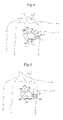
- FIG. 7is a schematic view of the method of making a subcutaneous path from the preferred incision and housing implantation point to a termination point for locating a subcutaneous electrode of the present invention
- FIG. 8is a schematic view of an introducer set for performing the method of lead insertion of any of the described embodiments
- FIG. 9is a schematic view of an alternative S-ICD of the present invention illustrating a lead subcutaneously and serpiginously implanted in the thorax of a patient for use particularly in children;
- FIG. 10is a schematic view of an alternate embodiment of an S-ICD of the present invention.
- FIG. 11is a schematic view of the S-ICD of FIG. 10 subcutaneously implanted in the thorax of a patient;
- FIG. 12is a schematic view of yet a further embodiment where the canister of the S-ICD of the present invention is shaped to be particularly useful in placing subcutaneously adjacent and parallel to a rib of a patient;
- FIG. 13is a schematic of a different embodiment where the canister of the S-ICD of the present invention is shaped to be particularly useful in placing subcutaneously adjacent and parallel to a rib of a patient.
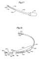
- FIG. 14is a schematic view of a Unitary Subcutaneous ICD (US-ICD) of the present invention.
- FIG. 15is a schematic view of the US-ICD subcutaneously implanted in the thorax of a patient
- FIG. 16is a schematic view of the method of making a subcutaneous path from the preferred incision for implanting the US-ICD.
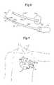
- FIG. 17is a schematic view of an introducer for performing the method of US-ICD implantation.
- FIG. 18is an exploded schematic view of an alternate embodiment of the present invention with a plug-in portion that contains operational circuitry and means for generating cardioversion/defibrillation shock waves.
- FIG. 19is a posterior perspective view of a lead electrode assembly in an embodiment of the present invention.
- FIG. 20is a top perspective view of an introducer for performing the method of lead insertion of the lead electrode assembly of FIG. 19 in an embodiment of the present invention
- FIG. 21( a )is a top perspective view of an extractor for performing the method of lead extraction of the lead electrode assembly of FIG. 19 in an embodiment of the present invention.
- FIG. 21( b )is a top perspective view of an extractor in the operational position for performing the method of lead extraction of the lead electrode assembly of FIG. 19 in an embodiment of the present invention.
- the S-ICDconsists of an electrically active canister 11 and a subcutaneous electrode 13 attached to the canister.
- the canisterhas an electrically active surface 15 that is electrically insulated from the electrode connector block 17 and the canister housing 16 via insulating area 14 .
- the canistercan be similar to numerous electrically active canisters commercially available in that the canister will contain a battery supply, capacitor and operational circuitry. Alternatively, the canister can be thin and elongated to conform to the intercostal space.
- the circuitrywill be able to monitor cardiac rhythms for tachycardia and fibrillation, and if detected, will initiate charging the capacitor and then delivering cardioversion/defibrillation energy through the active surface of the housing and to the subcutaneous electrode. Examples of such circuitry are described in U.S. Pat. Nos. 4,693,253 and 5,105,810, the entire disclosures of which are herein incorporated by reference.
- the canister circuitrycan provide cardioversion/defibrillation energy in different types of waveforms.
- a 100 uF biphasic waveformis used of approximately 10–20 ms total duration and with the initial phase containing approximately 2 ⁇ 3 of the energy, however, any type of waveform can be utilized such as monophasic, biphasic, multiphasic or alternative waveforms as is known in the art.
- the circuitrycan also provide transthoracic cardiac pacing energy.
- the optional circuitrywill be able to monitor the heart for bradycardia and/or tachycardia rhythms. Once a bradycardia or tachycardia rhythm is detected, the circuitry can then deliver appropriate pacing energy at appropriate intervals through the active surface and the subcutaneous electrode.
- Pacing stimulican be biphasic in one embodiment and similar in pulse amplitude to that used for conventional transthoracic pacing.
- This same circuitrycan also be used to deliver low amplitude shocks on the T-wave for induction of ventricular fibrillation for testing S-ICD performance in treating V-Fib as is described in U.S. Pat. No. 5,129,392, the entire disclosure of which is hereby incorporated by reference.
- the circuitrycan be provided with rapid induction of ventricular fibrillation or ventricular tachycardia using rapid ventricular pacing.
- Another optional way for inducing ventricular fibrillationwould be to provide a continuous low voltage, i.e., about 3 volts, across the heart during the entire cardiac cycle.
- the operational circuitrycan detect the presence of atrial fibrillation as described in Olson, W. et al. “Onset And Stability For Ventricular Tachyarrhythmia Detection in an Implantable Cardioverter and Defibrillator,” Computers in Cardiology (1986) pp. 167–170. Detection can be provided via R-R Cycle length instability detection algorithms. Once atrial fibrillation has been detected, the operational circuitry will then provide QRS synchronized atrial defibrillation/cardioversion using the same shock energy and waveshape characteristics used for ventricular defibrillation/cardioversion.
- the sensing circuitrywill utilize the electronic signals generated from the heart and will primarily detect QRS waves.
- the circuitrywill be programmed to detect only ventricular tachycardias or fibrillations.
- the detection circuitrywill utilize in its most direct form, a rate detection algorithm that triggers charging of the capacitor once the ventricular rate exceeds some predetermined level for a fixed period of time: for example, if the ventricular rate exceeds 240 bpm on average for more than 4 seconds. Once the capacitor is charged, a confirmatory rhythm check would ensure that the rate persists for at least another 1 second before discharge. Similarly, termination algorithms could be instituted that ensure that a rhythm less than 240 bpm persisting for at least 4 seconds before the capacitor charge is drained to an internal resistor.
- Detection, confirmation and termination algorithms as are described above and in the artcan be modulated to increase sensitivity and specificity by examining QRS beat-to-beat uniformity, QRS signal frequency content, R-R interval stability data, and signal amplitude characteristics all or part of which can be used to increase or decrease both sensitivity and specificity of S-ICD arrhythmia detection function.
- the sense circuitrycan check for the presence or the absence of respiration.
- the respiration ratecan be detected by monitoring the impedance across the thorax using subthreshold currents delivered across the active can and the high voltage subcutaneous lead electrode and monitoring the frequency in undulation in the waveform that results from the undulations of transthoracic impedance during the respiratory cycle. If there is no undulation, then the patent is not respiring and this lack of respiration can be used to confirm the QRS findings of cardiac arrest.
- the same techniquecan be used to provide information about the respiratory rate or estimate cardiac output as described in U.S. Pat. Nos. 6,095,987, 5,423,326, 4,450,527, the entire disclosures of which are incorporated herein by reference.
- the canister of the present inventioncan be made out of titanium alloy or other presently preferred electrically active canister designs. However, it is contemplated that a malleable canister that can conform to the curvature of the patient's chest will be preferred. In this way the patient can have a comfortable canister that conforms to the shape of the patient's rib cage. Examples of conforming canisters are provided in U.S. Pat. No. 5,645,586, the entire disclosure of which is herein incorporated by reference. Therefore, the canister can be made out of numerous materials such as medical grade plastics, metals, and alloys. In the preferred embodiment, the canister is smaller than 60 cc volume having a weight of less than 100 gms for long term wearability, especially in children.
- the canister and the lead of the S-ICDcan also use fractal or wrinkled surfaces to increase surface area to improve defibrillation capability. Because of the primary prevention role of the therapy and the likely need to reach energies over 40 Joules, a feature of one embodiment is that the charge time for the therapy, is intentionally left relatively long to allow capacitor charging within the limitations of device size. Examples of small ICD housings are disclosed in U.S. Pat. Nos. 5,597,956 and 5,405,363, the entire disclosures of which are herein incorporated by reference.
- the lead 21 for the subcutaneous electrodeis preferably composed of silicone or polyurethane insulation.
- the electrodeis connected to the canister at its proximal end via connection port 19 which is located on an electrically insulated area 17 of the canister.
- the electrode illustratedis a composite electrode with three different electrodes attached to the lead.
- an optional anchor segment 52is attached at the most distal end of the subcutaneous electrode for anchoring the electrode into soft tissue such that the electrode does not dislodge after implantation.
- the most distal electrode on the composite subcutaneous electrodeis a coil electrode 27 that is used for delivering the high voltage cardioversion/defibrillation energy across the heart.
- the coil cardioversion/defibrillation electrodeis about 5–10 cm in length.
- Proximal to the coil electrodeare two sense electrodes, a first sense electrode 25 is located proximally to the coil electrode and a second sense electrode 23 is located proximally to the first sense electrode.
- the sense electrodesare spaced far enough apart to be able to have good QRS detection. This spacing can range from 1 to 10 cm with 4 cm being presently preferred.
- the electrodesmay or may not be circumferential with the preferred embodiment.
- the sensing electrodesare electrically isolated from the cardioversion/defibrillation electrode via insulating areas 29 .
- Similar types of cardioversion/defibrillation electrodesare currently commercially available in a transvenous configuration.
- U.S. Pat. No. 5,534,022the entire disclosure of which is herein incorporated by reference, discloses a composite electrode with a coil cardioversion/defibrillation electrode and sense electrodes. Modifications to this arrangement are contemplated within the scope of the invention. One such modification is illustrated in FIG.
- FIG. 3illustrates yet a further embodiment where the two sensing electrodes are located at the distal end to the composite electrode with the coil electrode located proximally thereto.
- the sensing of QRS wavescan be carried out via sense electrodes on the canister housing or in combination with the cardioversion/defibrillation coil electrode and/or the subcutaneous lead sensing electrode(s).
- sensingcould be performed via the one coil electrode located on the subcutaneous electrode and the active surface on the canister housing.
- Another possibilitywould be to have only one sense electrode located on the subcutaneous electrode and the sensing would be performed by that one electrode and either the coil electrode on the subcutaneous electrode or by the active surface of the canister.
- the use of sensing electrodes on the canisterwould eliminate the need for sensing electrodes on the subcutaneous electrode.
- the canister sense electrodesmay also be placed on the electrically inactive surface of the canister. In the embodiment of FIG. 2 , there are actually four sensing electrodes, two on the subcutaneous lead and two on the canister. In the preferred embodiment, the ability to change which electrodes are used for sensing would be a programmable feature of the S-ICD to adapt to changes in the patient physiology and size (in the case of children) over time.
- the programmingcould be done via the use of physical switches on the canister, or as presently preferred, via the use of a programming wand or via a wireless connection to program the circuitry within the canister.
- the canistercould be employed as either a cathode or an anode of the S-ICD cardioversion/defibrillation system. If the canister is the cathode, then the subcutaneous coil electrode would be the anode. Likewise, if the canister is the anode, then the subcutaneous electrode would be the cathode.
- the active canister housingwill provide energy and voltage intermediate to that available with ICDs and most AEDs.
- the typical maximum voltage necessary for ICDs using most biphasic waveformsis approximately 750 Volts with an associated maximum energy of approximately 40 Joules.
- the typical maximum voltage necessary for AEDsis approximately 2000–5000 Volts with an associated maximum energy of approximately 200–360 Joules depending upon the model and waveform used.
- the S-ICD and the US-ICD of the present inventionuses maximum voltages in the range of about 50 to about 3500 Volts and is associated with energies of about 0.5 to about 350 Joules.
- the capacitance of the devicescan range from about 25 to about 200 micro farads.
- the S-ICD and US-ICD devicesprovide energy with a pulse width of approximately one millisecond to approximately 40 milliseconds.
- the devicescan provide pacing current of approximately one milliamp to approximately 250 milliamps.
- the sense circuitry contained within the canisteris highly sensitive and specific for the presence or absence of life threatening ventricular arrhythmias.
- Features of the detection algorithmare programmable and the algorithm is focused on the detection of V-FIB and high rate V-TACH (>240 bpm).
- V-FIB and high rate V-TACH>240 bpm.
- the S-ICD of the present inventionmay rarely be used for an actual life-threatening event, the simplicity of design and implementation allows it to be employed in large populations of patients at modest risk with modest cost by non-cardiac electrophysiologists. Consequently, the S-ICD of the present invention focuses mostly on the detection and therapy of the most malignant rhythm disorders.
- the upper rate rangeis programmable upward for use in children, known to have rapid supraventricular tachycardias and more rapid ventricular fibrillation. Energy levels also are programmable downward in order to allow treatment of neonates and infants.
- FIG. 4the optimal subcutaneous placement of the S-ICD of the present invention is illustrated.
- the actual location of the S-ICDis in a subcutaneous space that is developed during the implantation process.
- the heartis not exposed during this process and the heart is schematically illustrated in the figures only for help in understanding where the canister and coil electrode are three dimensionally located in the left mid-clavicular line approximately at the level of the inframammary crease at approximately the 5th rib.
- the lead 21 of the subcutaneous electrodetraverses in a subcutaneous path around the thorax terminating with its distal electrode end at the posterior axillary line ideally just lateral to the left scapula. This way the canister and subcutaneous cardioversion/defibrillation electrode provide a reasonably good pathway for current delivery to the majority of the ventricular myocardium.
- FIG. 5illustrates a different placement of the present invention.
- the S-ICD canister with the active housingis located in the left posterior axillary line approximately lateral to the tip of the inferior portion of the scapula. This location is especially useful in children.
- the lead 21 of the subcutaneous electrodetraverses in a subcutaneous path around the thorax terminating with its distal electrode end at the anterior precordial region, ideally in the inframammary crease.
- FIG. 6illustrates the embodiment of FIG. 1 subcutaneously implanted in the thorax with the proximal sense electrodes 23 and 25 located at approximately the left axillary line with the cardioversion/defibrillation electrode just lateral to the tip of the inferior portion of the scapula.
- the S-ICD canister 11is then placed subcutaneously at the location of the incision or medially at the subcutaneous region at the left inframammary crease.
- the subcutaneous electrode 13is placed with a specially designed curved introducer set 40 (see FIG. 8 ).
- the introducer setcomprises a curved trocar 42 and a stiff curved peel away sheath 44 .
- the peel away sheathis curved to allow for placement around the rib cage of the patient in the subcutaneous space created by the trocar.
- the sheathhas to be stiff enough to allow for the placement of the electrodes without the sheath collapsing or bending.
- the sheathis made out of a biocompatible plastic material and is perforated along its axial length to allow for it to split apart into two sections.
- the trocarhas a proximal handle 41 and a curved shaft 43 .
- the distal end 45 of the trocaris tapered to allow for dissection of a subcutaneous path 33 in the patient.
- the trocaris cannulated having a central Lumen 46 and terminating in an opening 48 at the distal end.
- Local anestheticsuch as lidocaine can be delivered, if necessary, through the lumen or through a curved and elongated needle designed to anesthetize the path to be used for trocar insertion should general anesthesia not be employed.
- the curved peel away sheath 44has a proximal pull tab 49 for breaking the sheath into two halves along its axial shaft 47 .
- the sheathis placed over a guidewire inserted through the trocar after the subcutaneous path has been created.
- the subcutaneous pathwayis then developed until it terminates subcutaneously at a location that, if a straight line were drawn from the canister location to the path termination point the line would intersect a substantial portion of the left ventricular mass of the patient.
- the guidewireis then removed leaving the peel away sheath.
- the subcutaneous lead systemis then inserted through the sheath until it is in the proper location. Once the subcutaneous lead system is in the proper location, the sheath is split in half using the pull tab 49 and removed. If more than one subcutaneous electrode is being used, a new curved peel away sheath can be used for each subcutaneous electrode.
- the S-ICDwill have prophylactic use in adults where chronic transvenous/epicardial ICD lead systems pose excessive risk or have already resulted in difficulty, such as sepsis or lead fractures. It is also contemplated that a major use of the S-ICD system of the present invention will be for prophylactic use in children who are at risk for having fatal arrhythmias, where chronic transvenous lead systems pose significant management problems. Additionally, with the use of standard transvenous ICDs in children, problems develop during patient growth in that the lead system does not accommodate the growth.
- FIG. 9illustrates the placement of the S-ICD subcutaneous lead system such that he problem that growth presents to the lead system is overcome.
- the distal end of the subcutaneous electrodeis placed in the same location as described above providing a good location for the coil cardioversion/defibrillation electrode 27 and the sensing electrodes 23 and 25 .
- the insulated lead 21is no longer placed in a taut configuration. Instead, the lead is serpiginously placed with a specially designed introducer trocar and sheath such that it has numerous waves or bends. As the child grows, the waves or bends will straighten out lengthening the lead system while maintaining proper electrode placement.
- a lead system with a distal tine or screw electrode anchoring system 52can also be incorporated into the distal tip of the lead to facilitate lead stability (see FIG. 1 ).
- Other anchoring systemscan also be used such as hooks, sutures, or the like.
- FIGS. 10 and 11illustrate another embodiment of the present S-ICD invention.
- the additional subcutaneous electrode 13 ′is essentially identical to the previously described electrode.
- the cardioversion/defibrillation energyis delivered between the active surface of the canister and the two coil electrodes 27 and 27 ′.
- provided in the canisteris means for selecting the optimum sensing arrangement between the four sense electrodes 23 , 23 ′, 25 , and 25 ′.
- the two electrodesare subcutaneously placed on the same side of the heart. As illustrated in FIG. 6 , one subcutaneous electrode 13 is placed inferiorly and the other electrode 13 ′ is placed superiorly. It is also contemplated with this dual subcutaneous electrode system that the canister and one subcutaneous electrode are the same polarity and the other subcutaneous electrode is the opposite polarity.
- FIGS. 12 and 13further embodiments are illustrated where the canister 11 of the S-ICD of the present invention is shaped to be particularly useful in placing subcutaneously adjacent and parallel to a rib of a patient.
- the canisteris long, thin, and curved to conform to the shape of the patient's rib.
- the canisterhas a diameter ranging from about 0.5 cm to about 2 cm without 1 cm being presently preferred.
- the canistercould have a rectangular or square cross sectional area as illustrated in FIG. 13 without falling outside of the scope of the present invention.
- the length of the canistercan vary depending on the size of the patient's thorax.
- the canistercan optionally have at least one sense electrode located on either the active surface of the inactive surface and the circuitry within the canister can be programmable as described above to allow for the selection of the best sense electrodes. It is presently preferred that the canister have two sense electrodes 26 and 28 located on the inactive surface of the canisters as illustrated, where the electrodes are spaced from about 1 to about 10 cm apart with a spacing of about 3 cm being presently preferred. However, the sense electrodes can be located on the active surface as described above.
- FIG. 12will be subcutaneously implanted adjacent and parallel to the left anterior 5th rib, either between the 4th and 5th ribs or between the 5th and 6th ribs. However other locations can be used.
- Another component of the S-ICD of the present inventionis a cutaneous test electrode system designed to simulate the subcutaneous high voltage shock electrode system as well as the QRS cardiac rhythm detection system.
- This test electrode systemis comprised of a cutaneous patch electrode of similar surface area and impedance to that of the S-ICD canister itself together with a cutaneous strip electrode comprising a defibrillation strip as well as two button electrodes for sensing of the QRS.
- Several cutaneous strip electrodesare available to allow for testing various bipole spacings to optimize signal detection comparable to the implantable system.
- FIGS. 14 to 18depict particular US-ICD embodiments of the present invention.
- the various sensing, shocking and pacing circuitry, described in detail above with respect to the S-ICD embodiments,may additionally be incorporated into the following US-ICD embodiments.
- particular aspects of any individual S-ICD embodiment discussed abovemay be incorporated, in whole or in part, into the US-ICD embodiments depicted in the following figures.
- the US-ICDconsists of a curved housing 1211 with a first and second end.
- the first end 1413is thicker than the second end 1215 .
- This thicker areahouses a battery supply, capacitor and operational circuitry for the US-ICD.
- the circuitrywill be able to monitor cardiac rhythms for tachycardia and fibrillation, and if detected, will initiate charging the capacitor and then delivering cardioversion/defibrillation energy through the two cardioversion/defibrillating electrodes 1417 and 1219 located on the outer surface of the two ends of the housing.
- the circuitrycan provide cardioversion/defibrillation energy in different types of waveforms.
- a 100 uF biphasic waveformis used of approximately 10–20 ms total duration and with the initial phase containing approximately 2 ⁇ 3 of the energy, however, any type of waveform can be utilized such as monophasic, biphasic, multiphasic or alternative waveforms as is known in the art.
- the housing of the present inventioncan be made out of titanium alloy or other presently preferred ICD designs. It is contemplated that the housing is also made out of biocompatible plastic materials that electronically insulate the electrodes from each other. However, it is contemplated that a malleable canister that can conform to the curvature of the patient's chest will be preferred. In this way the patient can have a comfortable canister that conforms to the unique shape of the patient's rib cage. Examples of conforming ICD housings are provided in U.S. Pat. No. 5,645,586, the entire disclosure of which is herein incorporated by reference. In the preferred embodiment, the housing is curved in the shape of a 5th rib of a person.
- the housingwill come in different incremental sizes to allow a good match between the size of the rib cage and the size of the US-ICD.
- the length of the US-ICDwill range from about 15 to about 50 cm. Because of the primary preventative role of the therapy and the need to reach energies over 40 Joules, a feature of the preferred embodiment is that the charge time for the therapy, intentionally be relatively long to allow capacitor charging within the limitations of device size.
- the thick end of the housingis currently needed to allow for the placement of the battery supply, operational circuitry, and capacitors. It is contemplated that the thick end will be about 0.5 cm to about 2 cm wide with about 1 cm being presently preferred. As microtechnology advances, the thickness of the housing will become smaller.
- the two cardioversion/defibrillation electrodes on the housingare used for delivering the high voltage cardioversion/defibrillation energy across the heart.
- the cardioversion/defibrillation electrodesare coil electrodes, however, other cardioversion/defibrillation electrodes could be used such as having electrically isolated active surfaces or platinum alloy electrodes.
- the coil cardioversion/defibrillation electrodesare about 5–10 cm in length.
- Located on the housing between the two cardioversion/defibrillation electrodesare two sense electrodes 1425 and 1427 . The sense electrodes are spaced far enough apart to be able to have good QRS detection. This spacing can range from 1 to 10 cm with 4 cm being presently preferred.
- the electrodesmay or may not be circumferential with the preferred embodiment. Having the electrodes non-circumferential and positioned outward, toward the skin surface, is a means to minimize muscle artifact and enhance QRS signal quality.
- the sensing electrodesare electrically isolated from the cardioversion/defibrillation electrode via insulating areas 1423 .
- Analogous types of cardioversion/defibrillation electrodesare currently commercially available in a transvenous configuration.
- U.S. Pat. No. 5,534,022the entire disclosure of which is herein incorporated by reference, discloses a composite electrode with a coil cardioversion/defibrillation electrode and sense electrodes. Modifications to this arrangement are contemplated within the scope of the invention.
- One such modificationis to have the sense electrodes at the two ends of the housing and have the cardioversion/defibrillation electrodes located in between the sense electrodes.
- Another modificationis to have three or more sense electrodes spaced throughout the housing and allow for the selection of the two best sensing electrodes. If three or more sensing electrodes are used, then the ability to change which electrodes are used for sensing would be a programmable feature of the US-ICD to adapt to changes in the patient physiology and size over time.
- the programmingcould be done via the use of physical switches on the canister, or as presently preferred, via the use of a programming wand or via a wireless connection to program the circuitry within the canister.
- FIG. 15the optimal subcutaneous placement of the US-ICD of the present invention is illustrated.
- the actual location of the US-ICDis in a subcutaneous space that is developed during the implantation process.
- the heartis not exposed during this process and the heart is schematically illustrated in the figures only for help in understanding where the device and its various electrodes are three dimensionally located in the thorax of the patient.
- the US-ICDis located between the left mid-clavicular line approximately at the level of the inframammary crease at approximately the 5 th rib and the posterior axillary line, ideally just lateral to the left scapula. This way the US-ICD provides a reasonably good pathway for current delivery to the majority of the ventricular myocardium.
- FIG. 16schematically illustrates the method for implanting the US-ICD of the present invention.
- An incision 1631is made in the left anterior axillary line approximately at the level of the cardiac apex.
- a subcutaneous pathwayis then created that extends posteriorly to allow placement of the US-ICD.
- the incisioncan be anywhere on the thorax deemed reasonable by the implanting physician although in the preferred embodiment, the US-ICD of the present invention will be applied in this region.
- the subcutaneous pathwayis created medially to the inframammary crease and extends posteriorly to the left posterior axillary line.
- the pathwayis developed with a specially designed curved introducer 1742 (see FIG. 17 ).
- the trocarhas a proximal handle 1641 and a curved shaft 1643 .
- the distal end 1745 of the trocaris tapered to allow for dissection of a subcutaneous path in the patient.
- the trocaris cannulated having a central lumen 1746 and terminating in an opening 1748 at the distal end.
- Local anestheticsuch as lidocaine can be delivered, if necessary, through the lumen or through a curved and elongated needle designed to anesthetize the path to be used for trocar insertion should general anesthesia not be employed.
- the US-ICDs of the present inventionvary in length and curvature.
- the US-ICDsare provided in incremental sizes for subcutaneous implantation in different sized patients.
- FIG. 18a different embodiment is schematically illustrated in exploded view which provides different sized US-ICDs that are easier to manufacture.
- the different sized US-ICDswill all have the same sized and shaped thick end 1413 .
- the thick endis hollow inside allowing for the insertion of a core operational member 1853 .
- the core membercomprises a housing 1857 which contains the battery supply, capacitor and operational circuitry for the US-ICD.
- the proximal end of the core memberhas a plurality of electronic plug connectors.
- Plug connectors 1861 and 1863are electronically connected to the sense electrodes via pressure fit connectors (not illustrated) inside the thick end which are standard in the art.
- Plug connectors 1865 and 1867are also electronically connected to the cardioverter/defibrillator electrodes via pressure fit connectors inside the thick end.
- the distal end of the core membercomprises an end cap 1855 , and a ribbed fitting 1859 which creates a water-tight seal when the core member is inserted into opening 1851 of the thick end of the US-ICD.
- the S-ICD and US-ICDhave the ability to detect and treat atrial rhythm disorders, including atrial fibrillation.
- the S-ICD and US-ICDhave two or more electrodes that provide a far-field view of cardiac electrical activity that includes the ability to record the P-wave of the electrocardiogram as well as the QRS.
- One can detect the onset and offset of atrial fibrillationby referencing to the P-wave recorded during normal sinus rhythm and monitoring for its change in rate, morphology, amplitude and frequency content. For example, a well-defined P-wave that abruptly disappeared and was replaced by a low-amplitude, variable morphology signal would be a strong indication of the absence of sinus rhythm and the onset of atrial fibrillation.
- the ventricular detection ratecould be monitored for stability of the R-R coupling interval.
- atrial fibrillationcan be recognized by providing a near constant irregularly irregular coupling interval on a beat-by-beat basis.
- An R-R interval plot during AFappears “cloudlike” in appearance when several hundred or thousands of R-R intervals are plotted over time when compared to sinus rhythm or other supraventricular arrhythmias.
- a distinguishing feature compared to other rhythms that are irregularly irregularis that the QRS morphology is similar on a beat-by-beat basis despite the irregularity in the R-R coupling interval.
- Atrial fibrillationmay be detected by seeking to compare the timing and amplitude relationship of the detected P-wave of the electrocardiogram to the detected QRS (R-wave) of the electrocardiogram.
- Normal sinus rhythmhas a fixed relationship that can be placed into a template matching algorithm that can be used as a reference point should the relationship change.
- the arrhythmiacan be treated by delivery of a synchronized shock using energy levels up to the maximum output of the device therapy for terminating atrial fibrillation or for other supraventricular arrhythmias.
- the S-ICD or US-ICD electrode systemcan be used to treat both atrial and ventricular arrhythmias not only with shock therapy but also with pacing therapy.
- onemay be able to use different electrode systems than what is used to treat ventricular arrhythmias.
- Another embodimentwould be to allow for different types of therapies (amplitude, waveform, capacitance, etc.) for atrial arrhythmias compared to ventricular arrhythmias.
- the core member of the different sized and shaped US-ICDwill all be the same size and shape. That way, during an implantation procedure, multiple sized US-ICDs can be available for implantation, each one without a core member. Once the implantation procedure is being performed, then the correct sized US-ICD can be selected and the core member can be inserted into the US-ICD and then programmed as described above. Another advantage of this configuration is when the battery within the core member needs replacing it can be done without removing the entire US-ICD.
- FIG. 19is a posterior perspective view of a lead electrode assembly in an embodiment of the present invention.
- the lead electrode assembly 1902comprises a connector portion 1904 , a housing 1906 and an electrode assembly 1908 .
- the connector portion 1904includes a pair of contacts 1918 and 1920 to provide a mechanical and electrical connection to an implantable cardioverter/defibrillator, such as a Subcutaneous Implantable Cardioverter/Defibrillator (S-ICD) or a Unitary Subcutaneous Implantable Cardioverter/Defibrillator (US-ICD).
- the housing 1906contains the electrical wiring to electrically connect a shocking/pacing electrode (not shown) on an anterior side 1922 of the electrode assembly 1908 and the connector portion 1904 .
- the shocking/pacing electrodedelivers the high voltage cardioversion/defibrillation energy across the heart.
- the shocking/pacing electrodecan also deliver the anti-arrhythmia pacing energy for across the heart.
- the electrode assembly 1908contains one or more sense electrode(s) (not shown) to provide various sense data as described above.
- the sense electrodesare electrically isolated from the shocking/pacing electrodes, but may be the same physical structure.
- the housing 1906further comprises a posterior side 1910 having a lumen 1912 and an anterior side 1914 .
- the lumen 1912provides an opening 1916 through the posterior side 1910 of the housing 1906 and runs the length of the body into the electrode assembly 1908 .
- the housing 1906 , the electrode assembly 1908 and the connector portion 1904(except the pair of contacts 1918 and 1920 ) comprises a biocompatible, flexible polymeric material.
- the lead electrode assembly 1902can range from approximately 25 cm to approximately 50 cm in length and from approximately 1 cm to approximately 4 cm in width.
- FIG. 20is a top perspective view of an introducer 2002 for performing the method of lead insertion of the lead electrode assembly 1902 of FIG. 19 in an embodiment of the present invention.
- the introducer 2002comprises an insertion portion 2004 and a handle 2006 .
- the handle 2006further comprises a flange 2008 .
- the introducer 2002comprises a biocompatible, non-flexible polymeric or metal material that is coated with a material such as Teflon for ease of insertion.
- the introduce 2002comprises stainless steel. It can be seen that other materials can be used to provide a non-flexible characteristic to the introducer 2002 .
- the insertion portion 2004can be pre-formed in shape, such as substantially flat or perhaps, curved to approximate the shape of the human thorax.
- the length and width of the insertion portion 2004are constructed to be slightly less than the width of the lumen 1912 and the length 1916 of the opening in the lead electrode assembly 1906 in FIG. 19 .
- the insertion portion 2004 of the introducer 2002can range from approximately 25 cm to approximately 50 cm in length and from approximately 1 cm to approximately 4 cm in width.
- the handle 2006 of the introducer 2002can range from approximately 4 cm to approximately 8 cm in length and from approximately 2 cm to approximately 5 cm in width.
- the introducer 2002 of FIG. 20is to be used to implant the lead electrode assembly 1902 of FIG. 19 .
- the physiciancan grasp the handle 2006 and insert the introducer 2002 into the opening 1916 through the lumen 1912 .
- the introducer 2002is inserted into the opening 1916 until being stopped by the flange 2008 on the handle 2006 .
- the combined introducer 2002 /lead electrode assembly 1902is implanted anywhere on the thorax.
- the introducer 2002can be used to create the subcutaneous pathway through the patient's thorax region. Because the introducer 2002 comprises a flexible material, the lead electrode assembly 1908 is easily inserted into the patient. After insertion to a proper location is completed, the physician can withdraw the introducer 2002 from the lumen 1912 .
- the flexible lead electrode assemblyis left in the patient and can comfortably comply with the patient's body movements.
- FIGS. 21( a ) and 21 ( b )are top perspective views of an extractor 2102 for performing the method of lead extraction of the lead electrode assembly 1902 of FIG. 19 in an embodiment of the present invention.
- the extractor 2102comprises an insertion portion 2104 and a handle assembly 2106 .
- the handle assembly 2106further comprises a tab 2116 seated in a housing 2118 , and a flange 2020 .
- the insertion portion 2104further comprises two prongs 2110 and 2112 , a wedge 2108 , and a connector 2114 .
- the connector 2114connects the wedge 2108 and the tab 2116 in the handle assembly 2106 .
- the two prongs 2110 and 2112further comprise one or more barbs 2218 disposed facing the outside edge of the insertion portion 2104 .
- the insertion portion 2104further includes a covering 2022 that is disposed around the prongs 2110 and 2112 , the wedge 2108 and the connector 2114 .
- the extractor 2102including the prongs 2110 and 2112 , barbs 2218 , and the wedge 2108 comprises a biocompatible, flexible polymeric material.
- the covering 2022comprises a biocompatible, flexible polymeric material.
- the covering 2022is coated with a material such as PTFE (Polytetrafluoroethylene) for ease of insertion.
- the insertion portion 2104can be pre-formed in shape, such as substantially flat or perhaps, curved to approximate the human thorax.
- the connector 2114comprises a wire or other flexible material.
- the length and width of the insertion portion 2104are constructed to be slightly less than the width of the lumen 1912 and the length 1916 of the opening in the lead electrode assembly 1906 in FIG. 19 .
- the insertion portion 2104 of the extractor 2102can range from approximately 25 cm to approximately 50 cm in length and from approximately 1 cm to approximately 4 cm in width.
- the handle 2106 of the extractor 2102can range from approximately 4 cm to approximately 8 cm in length and from approximately 2 cm to approximately 5 cm in width.
- the extractor 2102 of FIG. 21is to be used to extract the lead electrode assembly 1902 of FIG. 19 that has been implanted in a patient.
- the physiciangrasps the handle assembly 2106 and inserts the extractor 2102 into the opening 1916 of the lead electrode assembly 1902 through the lumen 1912 .
- the extractor 2102is inserted into the opening 1916 until being stopped by the flange 2020 on the handle assembly 2106 .
- the physicianpulls the tab 2116 , which in turn, pulls the wedge 2108 towards the prongs 2110 and 2112 as shown in FIG 21 ( b ).
- the wedge 2108spreads the prongs 2110 and 2112 apart and outward.
- the barbs 2218are forced into an inner portion of the opening 1916 of the lead electrode assembly 1902 .
- the physiciancan withdraw the lead electrode assembly 1902 from the patient by pulling on the handle assembly 2106 of the extractor 2102 .
Landscapes
- Health & Medical Sciences (AREA)
- Cardiology (AREA)
- Animal Behavior & Ethology (AREA)
- Nuclear Medicine, Radiotherapy & Molecular Imaging (AREA)
- Radiology & Medical Imaging (AREA)
- Life Sciences & Earth Sciences (AREA)
- Biomedical Technology (AREA)
- General Health & Medical Sciences (AREA)
- Public Health (AREA)
- Veterinary Medicine (AREA)
- Engineering & Computer Science (AREA)
- Heart & Thoracic Surgery (AREA)
- Electrotherapy Devices (AREA)
Abstract
Description
Claims (13)
Priority Applications (4)
| Application Number | Priority Date | Filing Date | Title |
|---|---|---|---|
| US10/011,949US7090682B2 (en) | 2000-09-18 | 2001-11-05 | Method and apparatus for extraction of a subcutaneous electrode |
| US10/124,159US7194302B2 (en) | 2000-09-18 | 2002-04-17 | Subcutaneous cardiac stimulator with small contact surface electrodes |
| US11/680,107US8447398B2 (en) | 2000-09-18 | 2007-02-28 | Subcutaneous implantable cardioverter-defibrillator placement methods |
| US13/887,652US8718760B2 (en) | 2000-09-18 | 2013-05-06 | Subcutaneous implantable cardioverter-defibrillator placement methods |
Applications Claiming Priority (3)
| Application Number | Priority Date | Filing Date | Title |
|---|---|---|---|
| US09/663,606US6647292B1 (en) | 2000-09-18 | 2000-09-18 | Unitary subcutaneous only implantable cardioverter-defibrillator and optional pacer |
| US09/663,607US6721597B1 (en) | 2000-09-18 | 2000-09-18 | Subcutaneous only implantable cardioverter defibrillator and optional pacer |
| US10/011,949US7090682B2 (en) | 2000-09-18 | 2001-11-05 | Method and apparatus for extraction of a subcutaneous electrode |
Related Parent Applications (3)
| Application Number | Title | Priority Date | Filing Date |
|---|---|---|---|
| US09/663,607Continuation-In-PartUS6721597B1 (en) | 2000-09-18 | 2000-09-18 | Subcutaneous only implantable cardioverter defibrillator and optional pacer |
| US09/663,606Continuation-In-PartUS6647292B1 (en) | 2000-09-18 | 2000-09-18 | Unitary subcutaneous only implantable cardioverter-defibrillator and optional pacer |
| US10/011,527Continuation-In-PartUS6834204B2 (en) | 2000-09-18 | 2001-11-05 | Method and apparatus for inducing defibrillation in a patient using a T-shock waveform |
Related Child Applications (3)
| Application Number | Title | Priority Date | Filing Date |
|---|---|---|---|
| US09/940,471Continuation-In-PartUS7076296B2 (en) | 2000-09-18 | 2001-08-27 | Method of supplying energy to subcutaneous cardioverter-defibrillator and pacer |
| US10/011,956Continuation-In-PartUS7120495B2 (en) | 2000-09-18 | 2001-11-05 | Flexible subcutaneous implantable cardioverter-defibrillator |
| US10/124,159Continuation-In-PartUS7194302B2 (en) | 2000-09-18 | 2002-04-17 | Subcutaneous cardiac stimulator with small contact surface electrodes |
Publications (2)
| Publication Number | Publication Date |
|---|---|
| US20020107559A1 US20020107559A1 (en) | 2002-08-08 |
| US7090682B2true US7090682B2 (en) | 2006-08-15 |
Family
ID=46204300
Family Applications (1)
| Application Number | Title | Priority Date | Filing Date |
|---|---|---|---|
| US10/011,949Expired - LifetimeUS7090682B2 (en) | 2000-09-18 | 2001-11-05 | Method and apparatus for extraction of a subcutaneous electrode |
Country Status (1)
| Country | Link |
|---|---|
| US (1) | US7090682B2 (en) |
Cited By (43)
| Publication number | Priority date | Publication date | Assignee | Title |
|---|---|---|---|---|
| US20070049979A1 (en)* | 2000-09-18 | 2007-03-01 | Cameron Health, Inc. | Bradycardia pacing in a subcutaneous device |
| US20070055309A1 (en)* | 2000-09-18 | 2007-03-08 | Cameron Health, Inc. | Active housing dual lead assembly |
| US20070179537A1 (en)* | 2001-11-05 | 2007-08-02 | Cameron Health, Inc. | Implantable Cardioverter-Defibrillator With Post-Shock Reset |
| US7623913B2 (en) | 2006-08-01 | 2009-11-24 | Cameron Health, Inc. | Implantable medical devices using heuristic filtering in cardiac event detection |
| US7623916B2 (en) | 2006-12-20 | 2009-11-24 | Cameron Health, Inc. | Implantable cardiac stimulus devices and methods with input recharge circuitry |
| US7706866B2 (en) | 2004-06-24 | 2010-04-27 | Cardiac Pacemakers, Inc. | Automatic orientation determination for ECG measurements using multiple electrodes |
| US7774064B2 (en) | 2003-12-12 | 2010-08-10 | Cardiac Pacemakers, Inc. | Cardiac response classification using retriggerable classification windows |
| US7783340B2 (en) | 2007-01-16 | 2010-08-24 | Cameron Health, Inc. | Systems and methods for sensing vector selection in an implantable medical device using a polynomial approach |
| US7797036B2 (en) | 2004-11-30 | 2010-09-14 | Cardiac Pacemakers, Inc. | Cardiac activation sequence monitoring for ischemia detection |
| US7805185B2 (en) | 2005-05-09 | 2010-09-28 | Cardiac Pacemakers, In. | Posture monitoring using cardiac activation sequences |
| US7877139B2 (en) | 2006-09-22 | 2011-01-25 | Cameron Health, Inc. | Method and device for implantable cardiac stimulus device lead impedance measurement |
| US7890159B2 (en) | 2004-09-30 | 2011-02-15 | Cardiac Pacemakers, Inc. | Cardiac activation sequence monitoring and tracking |
| US7917196B2 (en) | 2005-05-09 | 2011-03-29 | Cardiac Pacemakers, Inc. | Arrhythmia discrimination using electrocardiograms sensed from multiple implanted electrodes |
| US7917215B2 (en) | 2005-05-09 | 2011-03-29 | Cardiac Pacemakers, Inc. | Closed loop cardiac resynchronization therapy using cardiac activation sequence information |
| US7938782B2 (en) | 2003-08-18 | 2011-05-10 | Cardiac Pacemakers, Inc. | Prediction of disordered breathing |
| US7941208B2 (en) | 2006-11-29 | 2011-05-10 | Cardiac Pacemakers, Inc. | Therapy delivery for identified tachyarrhythmia episode types |
| US7996072B2 (en) | 2004-12-21 | 2011-08-09 | Cardiac Pacemakers, Inc. | Positionally adaptable implantable cardiac device |
| US8014851B2 (en) | 2006-09-26 | 2011-09-06 | Cameron Health, Inc. | Signal analysis in implantable cardiac treatment devices |
| US8116871B2 (en) | 2005-05-09 | 2012-02-14 | Cardiac Pacemakers, Inc. | Automatic capture verification using electrocardiograms sensed from multiple implanted electrodes |
| US8145310B2 (en) | 2003-12-11 | 2012-03-27 | Cardiac Pacemakers, Inc. | Non-captured intrinsic discrimination in cardiac pacing response classification |
| US8185202B2 (en) | 2005-04-26 | 2012-05-22 | Cardiac Pacemakers, Inc. | Implantable cardiac device for reduced phrenic nerve stimulation |
| US8200341B2 (en) | 2007-02-07 | 2012-06-12 | Cameron Health, Inc. | Sensing vector selection in a cardiac stimulus device with postural assessment |
| US8209013B2 (en) | 2006-09-14 | 2012-06-26 | Cardiac Pacemakers, Inc. | Therapeutic electrical stimulation that avoids undesirable activation |
| US8265736B2 (en) | 2007-08-07 | 2012-09-11 | Cardiac Pacemakers, Inc. | Method and apparatus to perform electrode combination selection |
| US8321014B2 (en) | 2008-10-06 | 2012-11-27 | Cardiac Pacemakers, Inc. | Dynamic cardiac resynchronization therapy by tracking intrinsic conduction |
| US8447398B2 (en) | 2000-09-18 | 2013-05-21 | Cameron Health, Inc. | Subcutaneous implantable cardioverter-defibrillator placement methods |
| US8521284B2 (en) | 2003-12-12 | 2013-08-27 | Cardiac Pacemakers, Inc. | Cardiac response classification using multisite sensing and pacing |
| US8527048B2 (en) | 2006-06-29 | 2013-09-03 | Cardiac Pacemakers, Inc. | Local and non-local sensing for cardiac pacing |
| US8649866B2 (en) | 2008-02-14 | 2014-02-11 | Cardiac Pacemakers, Inc. | Method and apparatus for phrenic stimulation detection |
| US8700138B2 (en) | 2006-08-18 | 2014-04-15 | Cardiac Pacemakers, Inc. | Methods and devices for determination of arrhythmia rate zone thresholds |
| US8712507B2 (en) | 2006-09-14 | 2014-04-29 | Cardiac Pacemakers, Inc. | Systems and methods for arranging and labeling cardiac episodes |
| US8718793B2 (en) | 2006-08-01 | 2014-05-06 | Cameron Health, Inc. | Electrode insertion tools, lead assemblies, kits and methods for placement of cardiac device electrodes |
| US8838234B2 (en) | 2000-09-18 | 2014-09-16 | Cameron Health, Inc. | Methods for implanting a subcutaneous defibrillator |
| US8915741B2 (en) | 2003-08-18 | 2014-12-23 | Cardiac Pacemakers, Inc. | Sleep quality data collection and evaluation |
| US9014819B2 (en) | 2003-09-18 | 2015-04-21 | Cardiac Pacemakers, Inc. | Autonomic arousal detection system and method |
| US9037239B2 (en) | 2007-08-07 | 2015-05-19 | Cardiac Pacemakers, Inc. | Method and apparatus to perform electrode combination selection |
| US9144683B2 (en) | 2000-09-18 | 2015-09-29 | Cameron Health, Inc. | Post-shock treatment in a subcutaneous device |
| US9579065B2 (en) | 2013-03-12 | 2017-02-28 | Cameron Health Inc. | Cardiac signal vector selection with monophasic and biphasic shape consideration |
| US9974944B2 (en) | 2010-07-29 | 2018-05-22 | Cameron Health, Inc. | Subcutaneous leads and methods of implant and explant |
| US10154794B2 (en) | 2014-04-25 | 2018-12-18 | Medtronic, Inc. | Implantable cardioverter-defibrillator (ICD) tachyarrhythmia detection modifications responsive to detected pacing |
| US10226197B2 (en) | 2014-04-25 | 2019-03-12 | Medtronic, Inc. | Pace pulse detector for an implantable medical device |
| US10448855B2 (en) | 2014-04-25 | 2019-10-22 | Medtronic, Inc. | Implantable medical device (IMD) sensing modifications responsive to detected pacing pulses |
| US10617402B2 (en) | 2015-07-22 | 2020-04-14 | Cameron Health, Inc. | Minimally invasive method to implant a subcutaneous electrode |
Families Citing this family (126)
| Publication number | Priority date | Publication date | Assignee | Title |
|---|---|---|---|---|
| US7097618B1 (en)* | 2003-03-12 | 2006-08-29 | Transoma Medical, Inc. | Devices and methods for detecting and treating inadequate tissue perfusion |
| US6754528B2 (en)* | 2001-11-21 | 2004-06-22 | Cameraon Health, Inc. | Apparatus and method of arrhythmia detection in a subcutaneous implantable cardioverter/defibrillator |
| CA2428873C (en)* | 2000-11-22 | 2013-05-14 | Medtronic, Inc. | Apparatus for detecting and treating ventricular arrhythmia |
| US7069075B2 (en)* | 2002-11-22 | 2006-06-27 | Medtronic, Inc. | Subcutaneous implantable cardioverter/defibrillator |
| US7189204B2 (en) | 2002-12-04 | 2007-03-13 | Cardiac Pacemakers, Inc. | Sleep detection using an adjustable threshold |
| US7529583B1 (en) | 2003-01-15 | 2009-05-05 | Transoma Medical, Inc. | Therapeutic device and method using feedback from implantable pressure sensor |
| US7392081B2 (en) | 2003-02-28 | 2008-06-24 | Cardiac Pacemakers, Inc. | Subcutaneous cardiac stimulator employing post-shock transthoracic asystole prevention pacing |
| US7117035B2 (en) | 2003-04-11 | 2006-10-03 | Cardiac Pacemakers, Inc. | Subcutaneous cardiac stimulation system with patient activity sensing |
| US7865233B2 (en) | 2003-04-11 | 2011-01-04 | Cardiac Pacemakers, Inc. | Subcutaneous cardiac signal discrimination employing non-electrophysiologic signal |
| US7047071B2 (en) | 2003-04-11 | 2006-05-16 | Cardiac Pacemakers, Inc. | Patient stratification for implantable subcutaneous cardiac monitoring and therapy |
| US7493175B2 (en) | 2003-04-11 | 2009-02-17 | Cardiac Pacemakers, Inc. | Subcutaneous lead with tined fixation |
| US7389138B2 (en)* | 2003-04-11 | 2008-06-17 | Cardiac Pacemakers, Inc. | Electrode placement determination for subcutaneous cardiac monitoring and therapy |
| US7499750B2 (en) | 2003-04-11 | 2009-03-03 | Cardiac Pacemakers, Inc. | Noise canceling cardiac electrodes |
| US20040220626A1 (en)* | 2003-04-11 | 2004-11-04 | Wagner Darrell Orvin | Distributed subcutaneous defibrillation system |
| US20040204734A1 (en)* | 2003-04-11 | 2004-10-14 | Wagner Darrell Orvin | Tunneling tool with subcutaneous transdermal illumination |
| US7302294B2 (en) | 2003-04-11 | 2007-11-27 | Cardiac Pacemakers, Inc. | Subcutaneous cardiac sensing and stimulation system employing blood sensor |
| US7349742B2 (en)* | 2003-04-11 | 2008-03-25 | Cardiac Pacemakers, Inc. | Expandable fixation elements for subcutaneous electrodes |
| US7218966B2 (en) | 2003-04-11 | 2007-05-15 | Cardiac Pacemakers, Inc. | Multi-parameter arrhythmia discrimination |
| US7236819B2 (en) | 2003-04-11 | 2007-06-26 | Cardiac Pacemakers, Inc. | Separation of a subcutaneous cardiac signal from a plurality of composite signals |
| US7529592B2 (en)* | 2003-04-11 | 2009-05-05 | Cardiac Pacemakers, Inc. | Subcutaneous electrode and lead with temporary pharmacological agents |
| US7702399B2 (en)* | 2003-04-11 | 2010-04-20 | Cardiac Pacemakers, Inc. | Subcutaneous electrode and lead with phoresis based pharmacological agent delivery |
| US7555335B2 (en) | 2003-04-11 | 2009-06-30 | Cardiac Pacemakers, Inc. | Biopotential signal source separation using source impedances |
| US8116868B2 (en) | 2003-04-11 | 2012-02-14 | Cardiac Pacemakers, Inc. | Implantable device with cardiac event audio playback |
| US7570997B2 (en) | 2003-04-11 | 2009-08-04 | Cardiac Pacemakers, Inc. | Subcutaneous cardiac rhythm management with asystole prevention therapy |
| US7499758B2 (en)* | 2003-04-11 | 2009-03-03 | Cardiac Pacemakers, Inc. | Helical fixation elements for subcutaneous electrodes |
| US7979122B2 (en) | 2003-04-11 | 2011-07-12 | Cardiac Pacemakers, Inc. | Implantable sudden cardiac death prevention device with reduced programmable feature set |
| US7566318B2 (en) | 2003-04-11 | 2009-07-28 | Cardiac Pacemakers, Inc. | Ultrasonic subcutaneous dissection tool incorporating fluid delivery |
| US8239045B2 (en) | 2003-06-04 | 2012-08-07 | Synecor Llc | Device and method for retaining a medical device within a vessel |
| US7082336B2 (en) | 2003-06-04 | 2006-07-25 | Synecor, Llc | Implantable intravascular device for defibrillation and/or pacing |
| CA2527909A1 (en)* | 2003-06-04 | 2005-01-06 | Synecor Llc | Intravascular electrophysiological system and methods |
| US7617007B2 (en) | 2003-06-04 | 2009-11-10 | Synecor Llc | Method and apparatus for retaining medical implants within body vessels |
| US7887493B2 (en) | 2003-09-18 | 2011-02-15 | Cardiac Pacemakers, Inc. | Implantable device employing movement sensing for detecting sleep-related disorders |
| US20050107838A1 (en)* | 2003-09-18 | 2005-05-19 | Lovett Eric G. | Subcutaneous cardiac rhythm management with disordered breathing detection and treatment |
| EP1670547B1 (en) | 2003-08-18 | 2008-11-12 | Cardiac Pacemakers, Inc. | Patient monitoring system |
| EP1701766A2 (en) | 2003-12-12 | 2006-09-20 | Synecor, LLC | Implantable medical device having pre-implant exoskeleton |
| CA2567769A1 (en)* | 2004-05-10 | 2005-11-24 | Transoma Medical, Inc. | Portable device for monitoring electrocardiographic signals and indices of blood flow |
| US7496408B2 (en)* | 2004-12-03 | 2009-02-24 | Medtronic, Inc. | Electrodes array for a pacemaker |
| US7680534B2 (en) | 2005-02-28 | 2010-03-16 | Cardiac Pacemakers, Inc. | Implantable cardiac device with dyspnea measurement |
| US8391990B2 (en) | 2005-05-18 | 2013-03-05 | Cardiac Pacemakers, Inc. | Modular antitachyarrhythmia therapy system |
| US20070049975A1 (en)* | 2005-09-01 | 2007-03-01 | Cates Adam W | Active can with dedicated defibrillation and sensing electrodes |
| US20070118180A1 (en) | 2005-11-18 | 2007-05-24 | Quan Ni | Cardiac resynchronization therapy for improved hemodynamics based on disordered breathing detection |
| US7761158B2 (en)* | 2005-12-20 | 2010-07-20 | Cardiac Pacemakers, Inc. | Detection of heart failure decompensation based on cumulative changes in sensor signals |
| US7899537B1 (en) | 2006-10-27 | 2011-03-01 | Pacesetter, Inc. | Pericardial cardioverter defibrillator |
| US7894915B1 (en)* | 2006-10-27 | 2011-02-22 | Pacesetter, Inc. | Implantable medical device |
| US9017341B2 (en)* | 2011-10-31 | 2015-04-28 | Pacesetter, Inc. | Multi-piece dual-chamber leadless intra-cardiac medical device and method of implanting same |
| AU2015204693B2 (en) | 2014-01-10 | 2017-03-23 | Cardiac Pacemakers, Inc. | Methods and systems for improved communication between medical devices |
| WO2015106015A1 (en) | 2014-01-10 | 2015-07-16 | Cardiac Pacemakers, Inc. | Systems and methods for detecting cardiac arrhythmias |
| CN107073275B (en) | 2014-08-28 | 2020-09-01 | 心脏起搏器股份公司 | Medical device with triggered blanking period |
| AU2016215606B2 (en) | 2015-02-06 | 2018-05-31 | Cardiac Pacemakers, Inc. | Systems and methods for treating cardiac arrhythmias |
| EP3253449B1 (en) | 2015-02-06 | 2018-12-12 | Cardiac Pacemakers, Inc. | Systems for safe delivery of electrical stimulation therapy |
| US10046167B2 (en) | 2015-02-09 | 2018-08-14 | Cardiac Pacemakers, Inc. | Implantable medical device with radiopaque ID tag |
| CN107530002B (en) | 2015-03-04 | 2021-04-30 | 心脏起搏器股份公司 | System and method for treating cardiac arrhythmias |
| US10050700B2 (en) | 2015-03-18 | 2018-08-14 | Cardiac Pacemakers, Inc. | Communications in a medical device system with temporal optimization |
| EP3270768B1 (en) | 2015-03-18 | 2023-12-13 | Cardiac Pacemakers, Inc. | Communications in a medical device system with link quality assessment |
| CN108136186B (en) | 2015-08-20 | 2021-09-17 | 心脏起搏器股份公司 | System and method for communication between medical devices |
| CN108136187B (en) | 2015-08-20 | 2021-06-29 | 心脏起搏器股份公司 | System and method for communication between medical devices |
| US9956414B2 (en) | 2015-08-27 | 2018-05-01 | Cardiac Pacemakers, Inc. | Temporal configuration of a motion sensor in an implantable medical device |
| US9968787B2 (en) | 2015-08-27 | 2018-05-15 | Cardiac Pacemakers, Inc. | Spatial configuration of a motion sensor in an implantable medical device |
| US10137305B2 (en) | 2015-08-28 | 2018-11-27 | Cardiac Pacemakers, Inc. | Systems and methods for behaviorally responsive signal detection and therapy delivery |
| WO2017040115A1 (en) | 2015-08-28 | 2017-03-09 | Cardiac Pacemakers, Inc. | System for detecting tamponade |
| US10226631B2 (en) | 2015-08-28 | 2019-03-12 | Cardiac Pacemakers, Inc. | Systems and methods for infarct detection |
| WO2017044389A1 (en) | 2015-09-11 | 2017-03-16 | Cardiac Pacemakers, Inc. | Arrhythmia detection and confirmation |
| WO2017062806A1 (en) | 2015-10-08 | 2017-04-13 | Cardiac Pacemakers, Inc. | Devices and methods for adjusting pacing rates in an implantable medical device |
| EP3389775B1 (en) | 2015-12-17 | 2019-09-25 | Cardiac Pacemakers, Inc. | Conducted communication in a medical device system |
| US10905886B2 (en) | 2015-12-28 | 2021-02-02 | Cardiac Pacemakers, Inc. | Implantable medical device for deployment across the atrioventricular septum |
| WO2017127548A1 (en) | 2016-01-19 | 2017-07-27 | Cardiac Pacemakers, Inc. | Devices for wirelessly recharging a rechargeable battery of an implantable medical device |
| CN109069840B (en) | 2016-02-04 | 2022-03-15 | 心脏起搏器股份公司 | Delivery system with force sensor for leadless cardiac devices |
| EP3436142B1 (en) | 2016-03-31 | 2025-04-30 | Cardiac Pacemakers, Inc. | Implantable medical device with rechargeable battery |
| US10668294B2 (en) | 2016-05-10 | 2020-06-02 | Cardiac Pacemakers, Inc. | Leadless cardiac pacemaker configured for over the wire delivery |
| US10328272B2 (en) | 2016-05-10 | 2019-06-25 | Cardiac Pacemakers, Inc. | Retrievability for implantable medical devices |
| EP3474945B1 (en) | 2016-06-27 | 2022-12-28 | Cardiac Pacemakers, Inc. | Cardiac therapy system using subcutaneously sensed p-waves for resynchronization pacing management |
| US11207527B2 (en) | 2016-07-06 | 2021-12-28 | Cardiac Pacemakers, Inc. | Method and system for determining an atrial contraction timing fiducial in a leadless cardiac pacemaker system |
| WO2018009392A1 (en) | 2016-07-07 | 2018-01-11 | Cardiac Pacemakers, Inc. | Leadless pacemaker using pressure measurements for pacing capture verification |
| EP3487579B1 (en) | 2016-07-20 | 2020-11-25 | Cardiac Pacemakers, Inc. | System for utilizing an atrial contraction timing fiducial in a leadless cardiac pacemaker system |
| WO2018035343A1 (en) | 2016-08-19 | 2018-02-22 | Cardiac Pacemakers, Inc. | Trans septal implantable medical device |
| EP3503970B1 (en) | 2016-08-24 | 2023-01-04 | Cardiac Pacemakers, Inc. | Cardiac resynchronization using fusion promotion for timing management |
| EP3503799B1 (en) | 2016-08-24 | 2021-06-30 | Cardiac Pacemakers, Inc. | Integrated multi-device cardiac resynchronization therapy using p-wave to pace timing |
| US10994145B2 (en) | 2016-09-21 | 2021-05-04 | Cardiac Pacemakers, Inc. | Implantable cardiac monitor |
| US10758737B2 (en) | 2016-09-21 | 2020-09-01 | Cardiac Pacemakers, Inc. | Using sensor data from an intracardially implanted medical device to influence operation of an extracardially implantable cardioverter |
| CN109803720B (en) | 2016-09-21 | 2023-08-15 | 心脏起搏器股份公司 | Leadless stimulation device having a housing containing its internal components and functioning as a terminal for a battery case and an internal battery |
| US10561330B2 (en) | 2016-10-27 | 2020-02-18 | Cardiac Pacemakers, Inc. | Implantable medical device having a sense channel with performance adjustment |
| EP3532161B1 (en) | 2016-10-27 | 2023-08-30 | Cardiac Pacemakers, Inc. | Implantable medical device with pressure sensor |
| US10413733B2 (en) | 2016-10-27 | 2019-09-17 | Cardiac Pacemakers, Inc. | Implantable medical device with gyroscope |
| CN109922860B (en) | 2016-10-27 | 2023-07-04 | 心脏起搏器股份公司 | Implantable medical device delivery system with integrated sensor |
| US10434314B2 (en) | 2016-10-27 | 2019-10-08 | Cardiac Pacemakers, Inc. | Use of a separate device in managing the pace pulse energy of a cardiac pacemaker |
| WO2018081275A1 (en) | 2016-10-27 | 2018-05-03 | Cardiac Pacemakers, Inc. | Multi-device cardiac resynchronization therapy with timing enhancements |
| US10434317B2 (en) | 2016-10-31 | 2019-10-08 | Cardiac Pacemakers, Inc. | Systems and methods for activity level pacing |
| EP3532157B1 (en) | 2016-10-31 | 2020-08-26 | Cardiac Pacemakers, Inc. | Systems for activity level pacing |
| WO2018089311A1 (en) | 2016-11-08 | 2018-05-17 | Cardiac Pacemakers, Inc | Implantable medical device for atrial deployment |
| WO2018089308A1 (en) | 2016-11-09 | 2018-05-17 | Cardiac Pacemakers, Inc. | Systems, devices, and methods for setting cardiac pacing pulse parameters for a cardiac pacing device |
| CN109963618B (en) | 2016-11-21 | 2023-07-04 | 心脏起搏器股份公司 | Leadless cardiac pacemaker with multi-mode communication |
| US10881869B2 (en) | 2016-11-21 | 2021-01-05 | Cardiac Pacemakers, Inc. | Wireless re-charge of an implantable medical device |
| WO2018093605A1 (en) | 2016-11-21 | 2018-05-24 | Cardiac Pacemakers, Inc. | Leadless cardiac pacemaker providing cardiac resynchronization therapy |
| US10639486B2 (en) | 2016-11-21 | 2020-05-05 | Cardiac Pacemakers, Inc. | Implantable medical device with recharge coil |
| US11147979B2 (en) | 2016-11-21 | 2021-10-19 | Cardiac Pacemakers, Inc. | Implantable medical device with a magnetically permeable housing and an inductive coil disposed about the housing |
| US11207532B2 (en) | 2017-01-04 | 2021-12-28 | Cardiac Pacemakers, Inc. | Dynamic sensing updates using postural input in a multiple device cardiac rhythm management system |
| US10029107B1 (en) | 2017-01-26 | 2018-07-24 | Cardiac Pacemakers, Inc. | Leadless device with overmolded components |
| JP7000438B2 (en) | 2017-01-26 | 2022-01-19 | カーディアック ペースメイカーズ, インコーポレイテッド | Human device communication with redundant message transmission |
| CN110198759B (en) | 2017-01-26 | 2023-08-11 | 心脏起搏器股份公司 | Leadless implantable device with removable fasteners |
| US10905872B2 (en) | 2017-04-03 | 2021-02-02 | Cardiac Pacemakers, Inc. | Implantable medical device with a movable electrode biased toward an extended position |
| CN110740779B (en) | 2017-04-03 | 2024-03-08 | 心脏起搏器股份公司 | Cardiac pacemaker with pacing pulse energy modulation based on sensed heart rate |
| CN111032148B (en) | 2017-08-18 | 2024-04-02 | 心脏起搏器股份公司 | Implantable medical device with pressure sensor |
| US10918875B2 (en) | 2017-08-18 | 2021-02-16 | Cardiac Pacemakers, Inc. | Implantable medical device with a flux concentrator and a receiving coil disposed about the flux concentrator |
| US11235163B2 (en) | 2017-09-20 | 2022-02-01 | Cardiac Pacemakers, Inc. | Implantable medical device with multiple modes of operation |
| US11185703B2 (en) | 2017-11-07 | 2021-11-30 | Cardiac Pacemakers, Inc. | Leadless cardiac pacemaker for bundle of his pacing |
| WO2019108830A1 (en) | 2017-12-01 | 2019-06-06 | Cardiac Pacemakers, Inc. | Leadless cardiac pacemaker with reversionary behavior |
| EP3717059B1 (en) | 2017-12-01 | 2024-11-20 | Cardiac Pacemakers, Inc. | Systems for detecting atrial contraction timing fiducials within a search window from a ventricularly implanted leadless cardiac pacemaker |
| CN111417433B (en) | 2017-12-01 | 2024-04-30 | 心脏起搏器股份公司 | Method and system for detecting atrial contraction timing reference during ventricular filling from a ventricularly implanted leadless cardiac pacemaker |
| WO2019108482A1 (en) | 2017-12-01 | 2019-06-06 | Cardiac Pacemakers, Inc. | Methods and systems for detecting atrial contraction timing fiducials and determining a cardiac interval from a ventricularly implanted leadless cardiac pacemaker |
| WO2019136148A1 (en) | 2018-01-04 | 2019-07-11 | Cardiac Pacemakers, Inc. | Dual chamber pacing without beat-to-beat communication |
| US11529523B2 (en) | 2018-01-04 | 2022-12-20 | Cardiac Pacemakers, Inc. | Handheld bridge device for providing a communication bridge between an implanted medical device and a smartphone |
| CN111886046B (en) | 2018-03-23 | 2025-05-27 | 美敦力公司 | AV-synchronized VFA cardiac therapy |
| JP2021518192A (en) | 2018-03-23 | 2021-08-02 | メドトロニック,インコーポレイテッド | VfA cardiac resynchronization therapy |
| EP3768160B1 (en) | 2018-03-23 | 2023-06-07 | Medtronic, Inc. | Vfa cardiac therapy for tachycardia |
| US11235161B2 (en) | 2018-09-26 | 2022-02-01 | Medtronic, Inc. | Capture in ventricle-from-atrium cardiac therapy |
| US11951313B2 (en) | 2018-11-17 | 2024-04-09 | Medtronic, Inc. | VFA delivery systems and methods |
| US12296177B2 (en) | 2018-12-21 | 2025-05-13 | Medtronic, Inc. | Delivery systems and methods for left ventricular pacing |
| US11679265B2 (en) | 2019-02-14 | 2023-06-20 | Medtronic, Inc. | Lead-in-lead systems and methods for cardiac therapy |
| US11697025B2 (en) | 2019-03-29 | 2023-07-11 | Medtronic, Inc. | Cardiac conduction system capture |
| US11213676B2 (en) | 2019-04-01 | 2022-01-04 | Medtronic, Inc. | Delivery systems for VfA cardiac therapy |
| US11712188B2 (en) | 2019-05-07 | 2023-08-01 | Medtronic, Inc. | Posterior left bundle branch engagement |
| US12042172B2 (en) | 2019-07-03 | 2024-07-23 | Valens Recovery Solutions LLC | Medical implant delivery device |
| US11305127B2 (en) | 2019-08-26 | 2022-04-19 | Medtronic Inc. | VfA delivery and implant region detection |
| US11813466B2 (en) | 2020-01-27 | 2023-11-14 | Medtronic, Inc. | Atrioventricular nodal stimulation |
| US11911168B2 (en) | 2020-04-03 | 2024-02-27 | Medtronic, Inc. | Cardiac conduction system therapy benefit determination |
| US11813464B2 (en) | 2020-07-31 | 2023-11-14 | Medtronic, Inc. | Cardiac conduction system evaluation |
Citations (113)
| Publication number | Priority date | Publication date | Assignee | Title |
|---|---|---|---|---|
| US3653387A (en) | 1970-05-08 | 1972-04-04 | Cardiac Electronics Inc | Protector circuit for cardiac apparatus |
| US3710374A (en) | 1970-03-16 | 1973-01-09 | Wester Instr Inc | Dual-slope and analog-to-digital converter wherein two analog input signals are selectively integrated with respect to time |
| US3911925A (en) | 1974-05-23 | 1975-10-14 | Jr Joe B Tillery | Ear trimming forceps |
| US4157720A (en) | 1977-09-16 | 1979-06-12 | Greatbatch W | Cardiac pacemaker |
| US4191942A (en) | 1978-06-08 | 1980-03-04 | National Semiconductor Corporation | Single slope A/D converter with sample and hold |
| US4223678A (en) | 1978-05-03 | 1980-09-23 | Mieczyslaw Mirowski | Arrhythmia recorder for use with an implantable defibrillator |
| US4248237A (en) | 1978-03-07 | 1981-02-03 | Needle Industries Limited | Cardiac pacemakers |
| US4291707A (en) | 1979-04-30 | 1981-09-29 | Mieczyslaw Mirowski | Implantable cardiac defibrillating electrode |
| US4314095A (en) | 1979-04-30 | 1982-02-02 | Mieczyslaw Mirowski | Device and method for making electrical contact |
| US4335756A (en)* | 1981-01-21 | 1982-06-22 | Texas Medical Products, Inc. | Sterilized medical tubing cover |
| US4402322A (en) | 1981-03-25 | 1983-09-06 | Medtronic, Inc. | Pacer output circuit |
| US4407288A (en) | 1981-02-18 | 1983-10-04 | Mieczyslaw Mirowski | Implantable heart stimulator and stimulation method |
| EP0095727A1 (en) | 1982-06-01 | 1983-12-07 | Purdue Research Foundation | Method and apparatus for inserting a defibrillator electrode and defibrillator electrode |
| US4424818A (en) | 1982-02-18 | 1984-01-10 | Medtronic, Inc. | Electrical lead and insertion tool |
| US4450527A (en) | 1982-06-29 | 1984-05-22 | Bomed Medical Mfg. Ltd. | Noninvasive continuous cardiac output monitor |
| US4567900A (en) | 1984-06-04 | 1986-02-04 | Moore J Paul | Internal deployable defibrillator electrode |
| US4574800A (en)* | 1984-12-07 | 1986-03-11 | Cordis Corporation | Implanted lead extractor |
| US4602637A (en) | 1983-01-11 | 1986-07-29 | Siemens Aktiengesellschaft | Heart pacemaker system |
| US4603705A (en) | 1984-05-04 | 1986-08-05 | Mieczyslaw Mirowski | Intravascular multiple electrode unitary catheter |
| US4693253A (en) | 1981-03-23 | 1987-09-15 | Medtronic, Inc. | Automatic implantable defibrillator and pacer |
| US4765341A (en) | 1981-06-22 | 1988-08-23 | Mieczyslaw Mirowski | Cardiac electrode with attachment fin |
| US4800883A (en) | 1986-04-02 | 1989-01-31 | Intermedics, Inc. | Apparatus for generating multiphasic defibrillation pulse waveform |
| US4830005A (en) | 1987-07-23 | 1989-05-16 | Siemens-Pacesetter, Inc. | Disposable in-package load test element for pacemakers |
| EP0316616A2 (en) | 1987-11-19 | 1989-05-24 | Siemens Aktiengesellschaft | Analog-digital converter |
| EP0347353A1 (en) | 1988-06-15 | 1989-12-20 | ATESYS, société anonyme | High performance defibrillator with several electrodes outside the heart |
| US4944300A (en) | 1987-04-28 | 1990-07-31 | Sanjeev Saksena | Method for high energy defibrillation of ventricular fibrillation in humans without a thoracotomy |
| DE3937594A1 (en)* | 1989-11-11 | 1991-05-16 | Vascomed Kathetertech | Extracting spiral electrode from organ of human body - inserting thin drawing element in internal lumen of spiral until nearly reaching electrode head |
| US5105810A (en) | 1990-07-24 | 1992-04-21 | Telectronics Pacing Systems, Inc. | Implantable automatic and haemodynamically responsive cardioverting/defibrillating pacemaker with means for minimizing bradycardia support pacing voltages |
| US5109842A (en) | 1990-09-24 | 1992-05-05 | Siemens Pacesetter, Inc. | Implantable tachyarrhythmia control system having a patch electrode with an integrated cardiac activity system |
| US5129392A (en) | 1990-12-20 | 1992-07-14 | Medtronic, Inc. | Apparatus for automatically inducing fibrillation |
| US5133353A (en) | 1990-04-25 | 1992-07-28 | Cardiac Pacemakers, Inc. | Implantable intravenous cardiac stimulation system with pulse generator housing serving as optional additional electrode |
| US5144946A (en) | 1991-08-05 | 1992-09-08 | Siemens Pacesetter, Inc. | Combined pacemaker substrate and electrical interconnect and method of assembly |
| EP0517494A2 (en) | 1991-06-07 | 1992-12-09 | Cardiac Pacemakers, Inc. | Insertion and tunneling tool for a subcutaneous wire patch electrode |
| EP0518599A2 (en) | 1991-06-14 | 1992-12-16 | Telectronics N.V. | Implantable pacemaker/cardioverter/defibrillator device and method incorporating multiple bradycardia support pacing rates |
| US5184616A (en) | 1991-10-21 | 1993-02-09 | Telectronics Pacing Systems, Inc. | Apparatus and method for generation of varying waveforms in arrhythmia control system |
| US5191901A (en) | 1991-08-29 | 1993-03-09 | Mieczyslaw Mirowski | Controlled discharge defibrillation electrode |
| US5203348A (en) | 1990-06-06 | 1993-04-20 | Cardiac Pacemakers, Inc. | Subcutaneous defibrillation electrodes |
| US5230337A (en) | 1990-06-06 | 1993-07-27 | Cardiac Pacemakers, Inc. | Process for implanting subcutaneous defibrillation electrodes |
| WO1993019809A1 (en) | 1992-04-06 | 1993-10-14 | Angemed, Inc. | System for treatment of ventricular tachycardia using a far-field pulse series |
| US5255692A (en) | 1992-09-04 | 1993-10-26 | Siemens Aktiengesellschaft | Subcostal patch electrode |
| US5261400A (en) | 1992-02-12 | 1993-11-16 | Medtronic, Inc. | Defibrillator employing transvenous and subcutaneous electrodes and method of use |
| US5331966A (en) | 1991-04-05 | 1994-07-26 | Medtronic, Inc. | Subcutaneous multi-electrode sensing system, method and pacer |
| US5366496A (en) | 1993-04-01 | 1994-11-22 | Cardiac Pacemakers, Inc. | Subcutaneous shunted coil electrode |
| EP0627237A1 (en) | 1991-06-26 | 1994-12-07 | Hector Osvaldo Trabucco | Pacemaker |
| US5376103A (en) | 1992-03-19 | 1994-12-27 | Angeion Corporation | Electrode system for implantable defibrillator |
| US5376104A (en) | 1992-02-07 | 1994-12-27 | Nihon Kohden Corporation | Defibrillator with electrocardiogram monitor |
| US5391200A (en) | 1992-09-30 | 1995-02-21 | Cardiac Pacemakers, Inc. | Defibrillation patch electrode having conductor-free resilient zone for minimally invasive deployment |
| EP0641573A2 (en) | 1993-08-31 | 1995-03-08 | Ventritex, Inc. | Method and apparatus for phase related cardiac defibrillation |
| US5405363A (en) | 1991-03-15 | 1995-04-11 | Angelon Corporation | Implantable cardioverter defibrillator having a smaller displacement volume |
| US5411539A (en) | 1993-08-31 | 1995-05-02 | Medtronic, Inc. | Active can emulator and method of use |
| US5411547A (en) | 1993-08-09 | 1995-05-02 | Pacesetter, Inc. | Implantable cardioversion-defibrillation patch electrodes having means for passive multiplexing of discharge pulses |
| US5413591A (en) | 1992-02-26 | 1995-05-09 | Angeion Corporation | Current truncated waveform defibrillator |
| US5423326A (en) | 1991-09-12 | 1995-06-13 | Drexel University | Apparatus and method for measuring cardiac output |
| EP0677301A1 (en) | 1994-04-14 | 1995-10-18 | Pacesetter AB | Electrode apparatus with a variable distance between the electrodes |
| US5476503A (en) | 1994-03-28 | 1995-12-19 | Pacesetter, Inc. | Sense array intelligent patch lead for an implantable defibrillator and method |
| US5509923A (en) | 1989-08-16 | 1996-04-23 | Raychem Corporation | Device for dissecting, grasping, or cutting an object |
| US5509928A (en) | 1995-03-02 | 1996-04-23 | Pacesetter, Inc. | Internally supported self-sealing septum |
| US5531766A (en) | 1995-01-23 | 1996-07-02 | Angeion Corporation | Implantable cardioverter defibrillator pulse generator kite-tail electrode system |
| US5531765A (en) | 1990-12-18 | 1996-07-02 | Ventritex, Inc. | Method and apparatus for producing configurable biphasic defibrillation waveforms |
| US5534022A (en) | 1994-11-22 | 1996-07-09 | Ventritex, Inc. | Lead having an integrated defibrillation/sensing electrode |
| US5534019A (en) | 1994-12-09 | 1996-07-09 | Ventritex, Inc. | Cardiac defibrillator with case that can be electrically active or inactive |
| US5549615A (en)* | 1989-11-11 | 1996-08-27 | Vascomed Institut Fur Kathetertechnologie Gmbh | Method and apparatus for extracting pacemaker electrodes embedded in the heart |
| US5597956A (en) | 1994-08-24 | 1997-01-28 | Murata Manufacturing Co., Ltd. | Capacitor type acceleration sensor |
| US5601607A (en) | 1992-03-19 | 1997-02-11 | Angeion Corporation | Implantable cardioverter defibrillator housing plated electrode |
| US5618287A (en) | 1994-01-28 | 1997-04-08 | Thomas J. Fogarty | Methods of surgically implanting a defibrillator electrode within a patient |
| US5620477A (en) | 1994-03-31 | 1997-04-15 | Ventritex, Inc. | Pulse generator with case that can be active or inactive |
| US5643328A (en) | 1996-07-19 | 1997-07-01 | Sulzer Intermedics Inc. | Implantable cardiac stimulation device with warning system having elongated stimulation electrode |
| US5645586A (en) | 1994-07-08 | 1997-07-08 | Ventritex, Inc. | Conforming implantable defibrillator |
| US5658321A (en) | 1995-06-09 | 1997-08-19 | Ventritex, Inc. | Conductive housing for implantable cardiac device |
| US5658317A (en) | 1995-08-14 | 1997-08-19 | Cardiac Pacemakers, Inc. | Threshold templating for digital AGC |
| WO1997029802A2 (en) | 1996-02-20 | 1997-08-21 | Advanced Bionics Corporation | Improved implantable microstimulator and systems employing the same |
| EP0536873B1 (en) | 1991-10-07 | 1997-09-17 | Telectronics N.V. | Apparatus for arrhythmia induction in arrhythmia control system |
| US5674260A (en) | 1996-02-23 | 1997-10-07 | Pacesetter, Inc. | Apparatus and method for mounting an activity sensor or other component within a pacemaker using a contoured hybrid lid |
| US5690683A (en) | 1995-06-19 | 1997-11-25 | Cardiac Pacemakers, Inc. | After potential removal in cardiac rhythm management device |
| US5697953A (en) | 1993-03-13 | 1997-12-16 | Angeion Corporation | Implantable cardioverter defibrillator having a smaller displacement volume |
| US5713926A (en) | 1990-04-25 | 1998-02-03 | Cardiac Pacemakers, Inc. | Implantable intravenous cardiac stimulation system with pulse generator housing serving as optional additional electrode |
| DE29801807U1 (en) | 1997-02-04 | 1998-06-04 | Mathar, Ralph, Humble | Device for use in surgical interventions, in particular in bypass operations |
| WO1998025349A1 (en) | 1996-12-03 | 1998-06-11 | Microchip Technology Incorporated | Slope analog-to-digital converter with ramp initiated prior to counter |
| US5766226A (en) | 1996-12-09 | 1998-06-16 | Angeion Corporation | Switched discharge pathways for ICD having multiple output capacitors |
| US5776169A (en) | 1997-04-28 | 1998-07-07 | Sulzer Intermedics Inc. | Implantable cardiac stimulator for minimally invasive implantation |
| US5814090A (en) | 1995-06-07 | 1998-09-29 | Angeion Corporation | Implantable medical device having heat-shrink conforming shield |
| US5836976A (en) | 1997-04-30 | 1998-11-17 | Medtronic, Inc. | Cardioversion energy reduction system |
| WO1999003534A1 (en) | 1997-07-17 | 1999-01-28 | Cpr Medical, Inc. | Defibrillator/pacemaker |
| US5895414A (en) | 1996-04-19 | 1999-04-20 | Sanchez-Zambrano; Sergio | Pacemaker housing |
| EP0917887A1 (en) | 1997-11-24 | 1999-05-26 | Pacesetter AB | A cardiac event detecting system for a heart stimulator |
| EP0923130A1 (en) | 1997-12-12 | 1999-06-16 | ELA MEDICAL (Société anonyme) | Electronic circuit, in particular for implantable active medical device, like a heart stimulator or defibrillator, and its manufacturing method |
| US5919222A (en) | 1998-01-06 | 1999-07-06 | Medtronic Inc. | Adjustable medical electrode lead |
| US5919211A (en) | 1996-06-27 | 1999-07-06 | Adams; Theodore P. | ICD power source using multiple single use batteries |
| US5925069A (en) | 1997-11-07 | 1999-07-20 | Sulzer Intermedics Inc. | Method for preparing a high definition window in a conformally coated medical device |
| WO1999037362A1 (en) | 1998-01-27 | 1999-07-29 | Vitatron Medical, B.V. | System for inducing tachycardia utilizing near field t-wave sensing |
| US5935154A (en) | 1997-01-24 | 1999-08-10 | Cardiac Pacemakers, Inc. | Implantable tissue stimulator incorporating deposited multilayer capacitor |
| US5941904A (en) | 1997-09-12 | 1999-08-24 | Sulzer Intermedics Inc. | Electromagnetic acceleration transducer for implantable medical device |
| US5944730A (en)* | 1997-05-19 | 1999-08-31 | Cardio Medical Solutions, Inc. | Device and method for assisting end-to-side anastomosis |
| WO1999053991A1 (en) | 1998-04-23 | 1999-10-28 | Alza Corporation | Trocar for inserting implants |
| US6014586A (en) | 1995-11-20 | 2000-01-11 | Pacesetter, Inc. | Vertically integrated semiconductor package for an implantable medical device |
| US6026325A (en) | 1998-06-18 | 2000-02-15 | Pacesetter, Inc. | Implantable medical device having an improved packaging system and method for making electrical connections |
| US6058328A (en) | 1996-08-06 | 2000-05-02 | Pacesetter, Inc. | Implantable stimulation device having means for operating in a preemptive pacing mode to prevent tachyarrhythmias and method thereof |
| WO2000041766A1 (en) | 1999-01-14 | 2000-07-20 | The Mower Family Chf Treatment Irrevocable Trust | Antitachycardial pacing |
| US6093173A (en) | 1998-09-09 | 2000-07-25 | Embol-X, Inc. | Introducer/dilator with balloon protection and methods of use |
| US6095987A (en) | 1996-04-17 | 2000-08-01 | Imagyn Medical Techonologies California, Inc. | Apparatus and methods of bioelectrical impedance analysis of blood flow |
| WO2000050120A1 (en) | 1999-02-25 | 2000-08-31 | St. Jude Medical Ab | Implantable tissue stimulating device |
| USH1905H (en) | 1997-03-21 | 2000-10-03 | Medtronic, Inc. | Mechanism for adjusting the exposed surface area and position of an electrode along a lead body |
| US6128531A (en) | 1998-04-01 | 2000-10-03 | Pacesetter, Inc. | Delivery of ICD shock capacitor energy via a controlled current source |
| US6144866A (en) | 1998-10-30 | 2000-11-07 | Medtronic, Inc. | Multiple sensor assembly for medical electric lead |
| US6185450B1 (en) | 1998-01-26 | 2001-02-06 | Physio-Control Manufacturing Corporation | Digital sliding pole fast-restore for an electrocardiograph display |
| WO2001043649A1 (en) | 1999-12-17 | 2001-06-21 | Fogarty Thomas J | Method and device for use in minimally invasive approximation of muscle and other tissue |
| WO2001056166A2 (en) | 2000-01-28 | 2001-08-02 | Infineon Technologies Ag | Method and analog-to-digital converter for converting an analog voltage into an arithmetical value |
| US20010027330A1 (en) | 1998-10-13 | 2001-10-04 | Physio-Control Manufacturing Corporation | Circuit for performing external pacing and biphasic defibrillation |
| WO2002022208A2 (en) | 2000-09-18 | 2002-03-21 | Cameron Health, Inc. | Subcutaneous only implantable cardioverter-defibrillator and optional pacer |
| WO2002024275A2 (en) | 2000-09-18 | 2002-03-28 | Cameron Health, Inc. | Unitary subcutaneous only implantable cardioverter-debribillator and optional pacer |
| US6411844B1 (en) | 1999-10-19 | 2002-06-25 | Pacesetter, Inc. | Fast recovery sensor amplifier circuit for implantable medical device |
| WO2002068046A1 (en) | 2000-11-03 | 2002-09-06 | Medtronic, Inc. | Mems switching circuit and method for an implantable medical device |
| WO2003018121A2 (en) | 2001-08-21 | 2003-03-06 | Medtronic,Inc. | Space-efficient implantable medical device assembly and manufacturing methods |
- 2001
- 2001-11-05USUS10/011,949patent/US7090682B2/ennot_activeExpired - Lifetime
Patent Citations (128)
| Publication number | Priority date | Publication date | Assignee | Title |
|---|---|---|---|---|
| US3710374A (en) | 1970-03-16 | 1973-01-09 | Wester Instr Inc | Dual-slope and analog-to-digital converter wherein two analog input signals are selectively integrated with respect to time |
| US3653387A (en) | 1970-05-08 | 1972-04-04 | Cardiac Electronics Inc | Protector circuit for cardiac apparatus |
| US3911925A (en) | 1974-05-23 | 1975-10-14 | Jr Joe B Tillery | Ear trimming forceps |
| US4157720A (en) | 1977-09-16 | 1979-06-12 | Greatbatch W | Cardiac pacemaker |
| US4248237A (en) | 1978-03-07 | 1981-02-03 | Needle Industries Limited | Cardiac pacemakers |
| US4223678A (en) | 1978-05-03 | 1980-09-23 | Mieczyslaw Mirowski | Arrhythmia recorder for use with an implantable defibrillator |
| US4191942A (en) | 1978-06-08 | 1980-03-04 | National Semiconductor Corporation | Single slope A/D converter with sample and hold |
| US4291707A (en) | 1979-04-30 | 1981-09-29 | Mieczyslaw Mirowski | Implantable cardiac defibrillating electrode |
| US4314095A (en) | 1979-04-30 | 1982-02-02 | Mieczyslaw Mirowski | Device and method for making electrical contact |
| US4335756A (en)* | 1981-01-21 | 1982-06-22 | Texas Medical Products, Inc. | Sterilized medical tubing cover |
| US4407288B1 (en) | 1981-02-18 | 2000-09-19 | Mieczyslaw Mirowski | Implantable heart stimulator and stimulation method |
| US4407288A (en) | 1981-02-18 | 1983-10-04 | Mieczyslaw Mirowski | Implantable heart stimulator and stimulation method |
| US4693253A (en) | 1981-03-23 | 1987-09-15 | Medtronic, Inc. | Automatic implantable defibrillator and pacer |
| US4402322A (en) | 1981-03-25 | 1983-09-06 | Medtronic, Inc. | Pacer output circuit |
| US4765341A (en) | 1981-06-22 | 1988-08-23 | Mieczyslaw Mirowski | Cardiac electrode with attachment fin |
| US4424818A (en) | 1982-02-18 | 1984-01-10 | Medtronic, Inc. | Electrical lead and insertion tool |
| EP0095727A1 (en) | 1982-06-01 | 1983-12-07 | Purdue Research Foundation | Method and apparatus for inserting a defibrillator electrode and defibrillator electrode |
| US4450527A (en) | 1982-06-29 | 1984-05-22 | Bomed Medical Mfg. Ltd. | Noninvasive continuous cardiac output monitor |
| US4602637A (en) | 1983-01-11 | 1986-07-29 | Siemens Aktiengesellschaft | Heart pacemaker system |
| US4603705A (en) | 1984-05-04 | 1986-08-05 | Mieczyslaw Mirowski | Intravascular multiple electrode unitary catheter |
| US4567900A (en) | 1984-06-04 | 1986-02-04 | Moore J Paul | Internal deployable defibrillator electrode |
| US4574800A (en)* | 1984-12-07 | 1986-03-11 | Cordis Corporation | Implanted lead extractor |
| US4800883A (en) | 1986-04-02 | 1989-01-31 | Intermedics, Inc. | Apparatus for generating multiphasic defibrillation pulse waveform |
| US4944300A (en) | 1987-04-28 | 1990-07-31 | Sanjeev Saksena | Method for high energy defibrillation of ventricular fibrillation in humans without a thoracotomy |
| US4830005A (en) | 1987-07-23 | 1989-05-16 | Siemens-Pacesetter, Inc. | Disposable in-package load test element for pacemakers |
| EP0316616A2 (en) | 1987-11-19 | 1989-05-24 | Siemens Aktiengesellschaft | Analog-digital converter |
| EP0316616A3 (en) | 1987-11-19 | 1992-06-03 | Siemens Aktiengesellschaft | Analog-digital converter |
| EP0347353A1 (en) | 1988-06-15 | 1989-12-20 | ATESYS, société anonyme | High performance defibrillator with several electrodes outside the heart |
| US5509923A (en) | 1989-08-16 | 1996-04-23 | Raychem Corporation | Device for dissecting, grasping, or cutting an object |
| DE3937594A1 (en)* | 1989-11-11 | 1991-05-16 | Vascomed Kathetertech | Extracting spiral electrode from organ of human body - inserting thin drawing element in internal lumen of spiral until nearly reaching electrode head |
| US5549615A (en)* | 1989-11-11 | 1996-08-27 | Vascomed Institut Fur Kathetertechnologie Gmbh | Method and apparatus for extracting pacemaker electrodes embedded in the heart |
| US5713926A (en) | 1990-04-25 | 1998-02-03 | Cardiac Pacemakers, Inc. | Implantable intravenous cardiac stimulation system with pulse generator housing serving as optional additional electrode |
| US5133353A (en) | 1990-04-25 | 1992-07-28 | Cardiac Pacemakers, Inc. | Implantable intravenous cardiac stimulation system with pulse generator housing serving as optional additional electrode |
| US5385574A (en) | 1990-04-25 | 1995-01-31 | Cardiac Pacemakers, Inc. | Implantable intravenous cardiac stimulation system with pulse generator housing serving as optional additional electrode |
| US5230337A (en) | 1990-06-06 | 1993-07-27 | Cardiac Pacemakers, Inc. | Process for implanting subcutaneous defibrillation electrodes |
| US5342407A (en) | 1990-06-06 | 1994-08-30 | Cardiac Pacemakers, Inc. | Body implantable defibrillation system |
| US5603732A (en) | 1990-06-06 | 1997-02-18 | Cardiac Pacemakers, Inc. | Subcutaneous defibrillation electrodes |
| US5203348A (en) | 1990-06-06 | 1993-04-20 | Cardiac Pacemakers, Inc. | Subcutaneous defibrillation electrodes |
| US5105810A (en) | 1990-07-24 | 1992-04-21 | Telectronics Pacing Systems, Inc. | Implantable automatic and haemodynamically responsive cardioverting/defibrillating pacemaker with means for minimizing bradycardia support pacing voltages |
| US5109842A (en) | 1990-09-24 | 1992-05-05 | Siemens Pacesetter, Inc. | Implantable tachyarrhythmia control system having a patch electrode with an integrated cardiac activity system |
| US5531765A (en) | 1990-12-18 | 1996-07-02 | Ventritex, Inc. | Method and apparatus for producing configurable biphasic defibrillation waveforms |
| US5129392A (en) | 1990-12-20 | 1992-07-14 | Medtronic, Inc. | Apparatus for automatically inducing fibrillation |
| US5405363A (en) | 1991-03-15 | 1995-04-11 | Angelon Corporation | Implantable cardioverter defibrillator having a smaller displacement volume |
| US5331966A (en) | 1991-04-05 | 1994-07-26 | Medtronic, Inc. | Subcutaneous multi-electrode sensing system, method and pacer |
| EP0517494B1 (en) | 1991-06-07 | 1996-09-04 | Cardiac Pacemakers, Inc. | Insertion and tunneling tool for a subcutaneous wire patch electrode |
| EP0517494A3 (en) | 1991-06-07 | 1993-03-17 | Cardiac Pacemakers, Inc. | Insertion and tunneling tool for a subcutaneous wire patch electrode |
| US5300106A (en) | 1991-06-07 | 1994-04-05 | Cardiac Pacemakers, Inc. | Insertion and tunneling tool for a subcutaneous wire patch electrode |
| EP0517494A2 (en) | 1991-06-07 | 1992-12-09 | Cardiac Pacemakers, Inc. | Insertion and tunneling tool for a subcutaneous wire patch electrode |
| EP0518599A2 (en) | 1991-06-14 | 1992-12-16 | Telectronics N.V. | Implantable pacemaker/cardioverter/defibrillator device and method incorporating multiple bradycardia support pacing rates |
| EP0518599B1 (en) | 1991-06-14 | 1997-09-24 | Telectronics N.V. | Implantable pacemaker/cardioverter/defibrillator device for incorporating multiple bradycardia support pacing rates |
| EP0627237A1 (en) | 1991-06-26 | 1994-12-07 | Hector Osvaldo Trabucco | Pacemaker |
| US5144946A (en) | 1991-08-05 | 1992-09-08 | Siemens Pacesetter, Inc. | Combined pacemaker substrate and electrical interconnect and method of assembly |
| US5191901A (en) | 1991-08-29 | 1993-03-09 | Mieczyslaw Mirowski | Controlled discharge defibrillation electrode |
| US5423326A (en) | 1991-09-12 | 1995-06-13 | Drexel University | Apparatus and method for measuring cardiac output |
| EP0536873B1 (en) | 1991-10-07 | 1997-09-17 | Telectronics N.V. | Apparatus for arrhythmia induction in arrhythmia control system |
| US5184616A (en) | 1991-10-21 | 1993-02-09 | Telectronics Pacing Systems, Inc. | Apparatus and method for generation of varying waveforms in arrhythmia control system |
| US5376104A (en) | 1992-02-07 | 1994-12-27 | Nihon Kohden Corporation | Defibrillator with electrocardiogram monitor |
| US5261400A (en) | 1992-02-12 | 1993-11-16 | Medtronic, Inc. | Defibrillator employing transvenous and subcutaneous electrodes and method of use |
| US5413591A (en) | 1992-02-26 | 1995-05-09 | Angeion Corporation | Current truncated waveform defibrillator |
| US5601607A (en) | 1992-03-19 | 1997-02-11 | Angeion Corporation | Implantable cardioverter defibrillator housing plated electrode |
| US5376103A (en) | 1992-03-19 | 1994-12-27 | Angeion Corporation | Electrode system for implantable defibrillator |
| WO1993019809A1 (en) | 1992-04-06 | 1993-10-14 | Angemed, Inc. | System for treatment of ventricular tachycardia using a far-field pulse series |
| EP0586858B1 (en) | 1992-09-04 | 1997-03-26 | Pacesetter AB | Subcostal patch electrode |
| US5255692A (en) | 1992-09-04 | 1993-10-26 | Siemens Aktiengesellschaft | Subcostal patch electrode |
| US5391200A (en) | 1992-09-30 | 1995-02-21 | Cardiac Pacemakers, Inc. | Defibrillation patch electrode having conductor-free resilient zone for minimally invasive deployment |
| US5697953A (en) | 1993-03-13 | 1997-12-16 | Angeion Corporation | Implantable cardioverter defibrillator having a smaller displacement volume |
| US5366496A (en) | 1993-04-01 | 1994-11-22 | Cardiac Pacemakers, Inc. | Subcutaneous shunted coil electrode |
| US5411547A (en) | 1993-08-09 | 1995-05-02 | Pacesetter, Inc. | Implantable cardioversion-defibrillation patch electrodes having means for passive multiplexing of discharge pulses |
| US5411539A (en) | 1993-08-31 | 1995-05-02 | Medtronic, Inc. | Active can emulator and method of use |
| EP0641573A2 (en) | 1993-08-31 | 1995-03-08 | Ventritex, Inc. | Method and apparatus for phase related cardiac defibrillation |
| EP0641573A3 (en) | 1993-08-31 | 1997-06-25 | Ventritex Inc | Method and apparatus for phase related cardiac defibrillation. |
| US5618287A (en) | 1994-01-28 | 1997-04-08 | Thomas J. Fogarty | Methods of surgically implanting a defibrillator electrode within a patient |
| US5690648A (en) | 1994-01-28 | 1997-11-25 | Thomas J. Fogarty | Methods and apparatus for rolling a defibrillator electrode |
| US5476503A (en) | 1994-03-28 | 1995-12-19 | Pacesetter, Inc. | Sense array intelligent patch lead for an implantable defibrillator and method |
| US5620477A (en) | 1994-03-31 | 1997-04-15 | Ventritex, Inc. | Pulse generator with case that can be active or inactive |
| EP0677301A1 (en) | 1994-04-14 | 1995-10-18 | Pacesetter AB | Electrode apparatus with a variable distance between the electrodes |
| US5645586A (en) | 1994-07-08 | 1997-07-08 | Ventritex, Inc. | Conforming implantable defibrillator |
| US5597956A (en) | 1994-08-24 | 1997-01-28 | Murata Manufacturing Co., Ltd. | Capacitor type acceleration sensor |
| US5534022A (en) | 1994-11-22 | 1996-07-09 | Ventritex, Inc. | Lead having an integrated defibrillation/sensing electrode |
| US5534019A (en) | 1994-12-09 | 1996-07-09 | Ventritex, Inc. | Cardiac defibrillator with case that can be electrically active or inactive |
| US5531766A (en) | 1995-01-23 | 1996-07-02 | Angeion Corporation | Implantable cardioverter defibrillator pulse generator kite-tail electrode system |
| US5509928A (en) | 1995-03-02 | 1996-04-23 | Pacesetter, Inc. | Internally supported self-sealing septum |
| US5814090A (en) | 1995-06-07 | 1998-09-29 | Angeion Corporation | Implantable medical device having heat-shrink conforming shield |
| US5658321A (en) | 1995-06-09 | 1997-08-19 | Ventritex, Inc. | Conductive housing for implantable cardiac device |
| US5690683A (en) | 1995-06-19 | 1997-11-25 | Cardiac Pacemakers, Inc. | After potential removal in cardiac rhythm management device |
| US5658317A (en) | 1995-08-14 | 1997-08-19 | Cardiac Pacemakers, Inc. | Threshold templating for digital AGC |
| US6014586A (en) | 1995-11-20 | 2000-01-11 | Pacesetter, Inc. | Vertically integrated semiconductor package for an implantable medical device |
| WO1997029802A2 (en) | 1996-02-20 | 1997-08-21 | Advanced Bionics Corporation | Improved implantable microstimulator and systems employing the same |
| US5674260A (en) | 1996-02-23 | 1997-10-07 | Pacesetter, Inc. | Apparatus and method for mounting an activity sensor or other component within a pacemaker using a contoured hybrid lid |
| US6095987A (en) | 1996-04-17 | 2000-08-01 | Imagyn Medical Techonologies California, Inc. | Apparatus and methods of bioelectrical impedance analysis of blood flow |
| US5895414A (en) | 1996-04-19 | 1999-04-20 | Sanchez-Zambrano; Sergio | Pacemaker housing |
| US5919211A (en) | 1996-06-27 | 1999-07-06 | Adams; Theodore P. | ICD power source using multiple single use batteries |
| US5643328A (en) | 1996-07-19 | 1997-07-01 | Sulzer Intermedics Inc. | Implantable cardiac stimulation device with warning system having elongated stimulation electrode |
| US6058328A (en) | 1996-08-06 | 2000-05-02 | Pacesetter, Inc. | Implantable stimulation device having means for operating in a preemptive pacing mode to prevent tachyarrhythmias and method thereof |
| WO1998025349A1 (en) | 1996-12-03 | 1998-06-11 | Microchip Technology Incorporated | Slope analog-to-digital converter with ramp initiated prior to counter |
| US5766226A (en) | 1996-12-09 | 1998-06-16 | Angeion Corporation | Switched discharge pathways for ICD having multiple output capacitors |
| US5935154A (en) | 1997-01-24 | 1999-08-10 | Cardiac Pacemakers, Inc. | Implantable tissue stimulator incorporating deposited multilayer capacitor |
| DE29801807U1 (en) | 1997-02-04 | 1998-06-04 | Mathar, Ralph, Humble | Device for use in surgical interventions, in particular in bypass operations |
| USH1905H (en) | 1997-03-21 | 2000-10-03 | Medtronic, Inc. | Mechanism for adjusting the exposed surface area and position of an electrode along a lead body |
| US5776169A (en) | 1997-04-28 | 1998-07-07 | Sulzer Intermedics Inc. | Implantable cardiac stimulator for minimally invasive implantation |
| US5836976A (en) | 1997-04-30 | 1998-11-17 | Medtronic, Inc. | Cardioversion energy reduction system |
| US5944730A (en)* | 1997-05-19 | 1999-08-31 | Cardio Medical Solutions, Inc. | Device and method for assisting end-to-side anastomosis |
| WO1999003534A1 (en) | 1997-07-17 | 1999-01-28 | Cpr Medical, Inc. | Defibrillator/pacemaker |
| US5941904A (en) | 1997-09-12 | 1999-08-24 | Sulzer Intermedics Inc. | Electromagnetic acceleration transducer for implantable medical device |
| US5925069A (en) | 1997-11-07 | 1999-07-20 | Sulzer Intermedics Inc. | Method for preparing a high definition window in a conformally coated medical device |
| EP0917887A1 (en) | 1997-11-24 | 1999-05-26 | Pacesetter AB | A cardiac event detecting system for a heart stimulator |
| EP0923130A1 (en) | 1997-12-12 | 1999-06-16 | ELA MEDICAL (Société anonyme) | Electronic circuit, in particular for implantable active medical device, like a heart stimulator or defibrillator, and its manufacturing method |
| US5919222A (en) | 1998-01-06 | 1999-07-06 | Medtronic Inc. | Adjustable medical electrode lead |
| US6185450B1 (en) | 1998-01-26 | 2001-02-06 | Physio-Control Manufacturing Corporation | Digital sliding pole fast-restore for an electrocardiograph display |
| WO1999037362A1 (en) | 1998-01-27 | 1999-07-29 | Vitatron Medical, B.V. | System for inducing tachycardia utilizing near field t-wave sensing |
| US6128531A (en) | 1998-04-01 | 2000-10-03 | Pacesetter, Inc. | Delivery of ICD shock capacitor energy via a controlled current source |
| WO1999053991A1 (en) | 1998-04-23 | 1999-10-28 | Alza Corporation | Trocar for inserting implants |
| US6026325A (en) | 1998-06-18 | 2000-02-15 | Pacesetter, Inc. | Implantable medical device having an improved packaging system and method for making electrical connections |
| US6093173A (en) | 1998-09-09 | 2000-07-25 | Embol-X, Inc. | Introducer/dilator with balloon protection and methods of use |
| US20010027330A1 (en) | 1998-10-13 | 2001-10-04 | Physio-Control Manufacturing Corporation | Circuit for performing external pacing and biphasic defibrillation |
| US6144866A (en) | 1998-10-30 | 2000-11-07 | Medtronic, Inc. | Multiple sensor assembly for medical electric lead |
| WO2000041766A1 (en) | 1999-01-14 | 2000-07-20 | The Mower Family Chf Treatment Irrevocable Trust | Antitachycardial pacing |
| WO2000050120A1 (en) | 1999-02-25 | 2000-08-31 | St. Jude Medical Ab | Implantable tissue stimulating device |
| US6411844B1 (en) | 1999-10-19 | 2002-06-25 | Pacesetter, Inc. | Fast recovery sensor amplifier circuit for implantable medical device |
| WO2001043649A1 (en) | 1999-12-17 | 2001-06-21 | Fogarty Thomas J | Method and device for use in minimally invasive approximation of muscle and other tissue |
| WO2001056166A2 (en) | 2000-01-28 | 2001-08-02 | Infineon Technologies Ag | Method and analog-to-digital converter for converting an analog voltage into an arithmetical value |
| WO2002022208A2 (en) | 2000-09-18 | 2002-03-21 | Cameron Health, Inc. | Subcutaneous only implantable cardioverter-defibrillator and optional pacer |
| WO2002024275A2 (en) | 2000-09-18 | 2002-03-28 | Cameron Health, Inc. | Unitary subcutaneous only implantable cardioverter-debribillator and optional pacer |
| WO2002024275A3 (en) | 2000-09-18 | 2002-05-30 | Cameron Health Inc | Unitary subcutaneous only implantable cardioverter-debribillator and optional pacer |
| WO2002022208A3 (en) | 2000-09-18 | 2002-06-06 | Cameron Health Inc | Subcutaneous only implantable cardioverter-defibrillator and optional pacer |
| US6647292B1 (en) | 2000-09-18 | 2003-11-11 | Cameron Health | Unitary subcutaneous only implantable cardioverter-defibrillator and optional pacer |
| WO2002068046A1 (en) | 2000-11-03 | 2002-09-06 | Medtronic, Inc. | Mems switching circuit and method for an implantable medical device |
| WO2003018121A2 (en) | 2001-08-21 | 2003-03-06 | Medtronic,Inc. | Space-efficient implantable medical device assembly and manufacturing methods |
Non-Patent Citations (13)
| Title |
|---|
| Friedman, Richard A. et al., "Implantable Defibrillators In Children: From Whence to Shock," Journal of Cardiovascular Electrophysiology, vol. 12, No. 3, Mar. 2001, pp. 361-362. |
| Gradaus, Rainer et al., "Nonthoracotomy Implantable Cardioverter Defibrillator Placement in Children: Use of Subcutaneous Array Leads and Abdominally Placed Implantable Cardioverter Defibrillators in Children," Journal of Cardiovascular Electrophysiology, vol. 12, No. 3, Mar. 2001, pp. 356-360. |
| Mirowski, M. et al., "Automatic Detection and Defibrillation of Lethal Arrhythmias-A New Concept," JAMA, vol. 213, No. 4, Jul. 27, 1970, pp. 615-616. |
| Olson, Walter H. et al., "Onset and Stability for Ventricular Tachyarrhythmia Detection in an Implantable Pacer-Cardioverter-Defribrillator," IEEE, (1987) pp. 167-170. |
| Schuder, John C. et al., "Experimental Ventricular Defibrillation with an Automatic and Completely Implanted System," Trans. Amer. Soc. Artif. Int. Organs, vol. XVI (1970) pp. 207-212. |
| Schuder, John C. et al., "Standby Implanted Defibrillators," Arch Intern. Med, vol. 127, Feb. 1971, p. 317 (single sheet). |
| Schuder, John C. et al., "Transthoracic Ventricular Defibrillation in the Dog with Truncated and Untruncated Exponential Stimuli," IEEE Transactions on Bio-Medical Engineering, vol. BME-18, No. 6, Nov. 1971, pp. 410-415. |
| Schuder, John C., "Completely Implanted Defibrillator," JAMA, vol. 214, No. 6, Nov. 9, 1970. p. 1123 (single sheet). |
| Schuder, John C., "The Role of an Engineering Oriented Medical Research Group in Developing Improved Methods and Devices for Achieving Ventricular Defibrillation: The University of Missouri Experience," PACE, vol. 16, Jan. 1993, pp. 95-124. |
| Tietze U. et al., "Halbleiter-Schaltungstechnik," (C) Springer-Verlag (Berlin, Germany), (1991), pp. 784-786. |
| Tietze U. et al., "Halbleiter-Schaltungstechnik," © Springer-Verlag (Berlin, Germany), (1991), pp. 784-786. |
| U.S. Appl. No. 09/663,607 to Bardy et al., filed Sep. 18, 2000. |
| Walters, R.A. et al., "Analog to Digital Conversion Techniques in Implantable Devices," Annual International Conference of the IEEE Engineering in Medicine and Biology Society, vol. 13 No. 4 (1991) p. 1674-1676. |
Cited By (89)
| Publication number | Priority date | Publication date | Assignee | Title |
|---|---|---|---|---|
| US9144683B2 (en) | 2000-09-18 | 2015-09-29 | Cameron Health, Inc. | Post-shock treatment in a subcutaneous device |
| US8838234B2 (en) | 2000-09-18 | 2014-09-16 | Cameron Health, Inc. | Methods for implanting a subcutaneous defibrillator |
| US20070060960A1 (en)* | 2000-09-18 | 2007-03-15 | Cameron Health, Inc. | Anterior active housing subcutaneous positioning methods |
| US20070060958A1 (en)* | 2000-09-18 | 2007-03-15 | Cameron Health, Inc. | Anterior positioning inactive housing |
| US20070060957A1 (en)* | 2000-09-18 | 2007-03-15 | Cameron Health, Inc. | Anterior positioning on opposing sides of sternum |
| US8014862B2 (en) | 2000-09-18 | 2011-09-06 | Cameron Health, Inc. | Anterior active housing subcutaneous positioning methods |
| US7349736B2 (en) | 2000-09-18 | 2008-03-25 | Cameron Health, Inc. | Active housing dual lead assembly |
| US7774059B2 (en) | 2000-09-18 | 2010-08-10 | Cameron Health | Anterior positioning inactive housing |
| US7835790B2 (en) | 2000-09-18 | 2010-11-16 | Cameron Health, Inc. | Anterior active housing subcutaneous positioning methods |
| US20070049979A1 (en)* | 2000-09-18 | 2007-03-01 | Cameron Health, Inc. | Bradycardia pacing in a subcutaneous device |
| US20070055309A1 (en)* | 2000-09-18 | 2007-03-08 | Cameron Health, Inc. | Active housing dual lead assembly |
| US7774058B2 (en) | 2000-09-18 | 2010-08-10 | Cameron Health, Inc. | Anterior positioning on opposing sides of sternum |
| US7751885B2 (en) | 2000-09-18 | 2010-07-06 | Cameron Health, Inc. | Bradycardia pacing in a subcutaneous device |
| US8447398B2 (en) | 2000-09-18 | 2013-05-21 | Cameron Health, Inc. | Subcutaneous implantable cardioverter-defibrillator placement methods |
| US7769445B2 (en) | 2001-11-05 | 2010-08-03 | Cameron Health, Inc. | Implantable cardioverter-defibrillator with post-shock reset |
| US20070179537A1 (en)* | 2001-11-05 | 2007-08-02 | Cameron Health, Inc. | Implantable Cardioverter-Defibrillator With Post-Shock Reset |
| US7938782B2 (en) | 2003-08-18 | 2011-05-10 | Cardiac Pacemakers, Inc. | Prediction of disordered breathing |
| US8915741B2 (en) | 2003-08-18 | 2014-12-23 | Cardiac Pacemakers, Inc. | Sleep quality data collection and evaluation |
| US9014819B2 (en) | 2003-09-18 | 2015-04-21 | Cardiac Pacemakers, Inc. | Autonomic arousal detection system and method |
| US9008771B2 (en) | 2003-12-11 | 2015-04-14 | Cardiac Pacemakers, Inc. | Non-captured intrinsic discrimination in cardiac pacing response classification |
| US8145310B2 (en) | 2003-12-11 | 2012-03-27 | Cardiac Pacemakers, Inc. | Non-captured intrinsic discrimination in cardiac pacing response classification |
| US8521284B2 (en) | 2003-12-12 | 2013-08-27 | Cardiac Pacemakers, Inc. | Cardiac response classification using multisite sensing and pacing |
| US7774064B2 (en) | 2003-12-12 | 2010-08-10 | Cardiac Pacemakers, Inc. | Cardiac response classification using retriggerable classification windows |
| US9308375B2 (en) | 2003-12-12 | 2016-04-12 | Cardiac Pacemakers, Inc. | Cardiac response classification using multisite sensing and pacing |
| US8843199B2 (en) | 2003-12-12 | 2014-09-23 | Cardiac Pacemakers, Inc. | Cardiac response classification using multisite sensing and pacing |
| US10898142B2 (en) | 2003-12-12 | 2021-01-26 | Cardiac Pacemakers, Inc. | Cardiac response classification using retriggerable classification windows |
| US9993205B2 (en) | 2003-12-12 | 2018-06-12 | Cardiac Pacemakers, Inc. | Cardiac response classification using retriggerable classification windows |
| US7706866B2 (en) | 2004-06-24 | 2010-04-27 | Cardiac Pacemakers, Inc. | Automatic orientation determination for ECG measurements using multiple electrodes |
| US7941206B2 (en) | 2004-06-24 | 2011-05-10 | Cardiac Pacemakers, Inc. | Automatic orientation determination for ECG measurements using multiple electrodes |
| US8380293B2 (en) | 2004-09-30 | 2013-02-19 | Cardiac Pacemakers, Inc. | Cardiac activation sequence monitoring and tracking |
| US7890159B2 (en) | 2004-09-30 | 2011-02-15 | Cardiac Pacemakers, Inc. | Cardiac activation sequence monitoring and tracking |
| US8626276B2 (en) | 2004-11-30 | 2014-01-07 | Cardiac Pacemakers, Inc. | Cardiac activation sequence monitoring for ischemia detection |
| US7797036B2 (en) | 2004-11-30 | 2010-09-14 | Cardiac Pacemakers, Inc. | Cardiac activation sequence monitoring for ischemia detection |
| US7996072B2 (en) | 2004-12-21 | 2011-08-09 | Cardiac Pacemakers, Inc. | Positionally adaptable implantable cardiac device |
| US8185202B2 (en) | 2005-04-26 | 2012-05-22 | Cardiac Pacemakers, Inc. | Implantable cardiac device for reduced phrenic nerve stimulation |
| US8260421B2 (en) | 2005-04-26 | 2012-09-04 | Cardiac Pacemakers, Inc. | Method for reducing phrenic nerve stimulation |
| US8116871B2 (en) | 2005-05-09 | 2012-02-14 | Cardiac Pacemakers, Inc. | Automatic capture verification using electrocardiograms sensed from multiple implanted electrodes |
| US7917215B2 (en) | 2005-05-09 | 2011-03-29 | Cardiac Pacemakers, Inc. | Closed loop cardiac resynchronization therapy using cardiac activation sequence information |
| US7917196B2 (en) | 2005-05-09 | 2011-03-29 | Cardiac Pacemakers, Inc. | Arrhythmia discrimination using electrocardiograms sensed from multiple implanted electrodes |
| US7805185B2 (en) | 2005-05-09 | 2010-09-28 | Cardiac Pacemakers, In. | Posture monitoring using cardiac activation sequences |
| US8321002B2 (en) | 2005-05-09 | 2012-11-27 | Cardiac Pacemakers, Inc. | Arrhythmia discrimination using ECG's sensed from multiple implanted electrodes |
| US8965530B2 (en) | 2006-05-26 | 2015-02-24 | Cameron Health, Inc. | Implantable cardiac devices and methods using an x/y counter |
| US9357969B2 (en) | 2006-05-26 | 2016-06-07 | Cameron Health, Inc. | Sensing vector selection in a cardiac stimulus device with postural assessment |
| US9744366B2 (en) | 2006-05-26 | 2017-08-29 | Cameron Health, Inc. | Sensing vector selection in a cardiac stimulus device with postural assessment |
| US8527048B2 (en) | 2006-06-29 | 2013-09-03 | Cardiac Pacemakers, Inc. | Local and non-local sensing for cardiac pacing |
| US8718793B2 (en) | 2006-08-01 | 2014-05-06 | Cameron Health, Inc. | Electrode insertion tools, lead assemblies, kits and methods for placement of cardiac device electrodes |
| US7623913B2 (en) | 2006-08-01 | 2009-11-24 | Cameron Health, Inc. | Implantable medical devices using heuristic filtering in cardiac event detection |
| US9216284B2 (en) | 2006-08-01 | 2015-12-22 | Cameron Health, Inc. | Electrode insertion tools, lead assemblies, kits and methods for placement of cardiac device electrodes |
| US8700138B2 (en) | 2006-08-18 | 2014-04-15 | Cardiac Pacemakers, Inc. | Methods and devices for determination of arrhythmia rate zone thresholds |
| US8712507B2 (en) | 2006-09-14 | 2014-04-29 | Cardiac Pacemakers, Inc. | Systems and methods for arranging and labeling cardiac episodes |
| US8209013B2 (en) | 2006-09-14 | 2012-06-26 | Cardiac Pacemakers, Inc. | Therapeutic electrical stimulation that avoids undesirable activation |
| US7877139B2 (en) | 2006-09-22 | 2011-01-25 | Cameron Health, Inc. | Method and device for implantable cardiac stimulus device lead impedance measurement |
| US8014851B2 (en) | 2006-09-26 | 2011-09-06 | Cameron Health, Inc. | Signal analysis in implantable cardiac treatment devices |
| US8688204B2 (en) | 2006-11-29 | 2014-04-01 | Cardiac Pacemakers, Inc. | Therapy delivery for identified tachyarrhythmia episode types |
| US7941208B2 (en) | 2006-11-29 | 2011-05-10 | Cardiac Pacemakers, Inc. | Therapy delivery for identified tachyarrhythmia episode types |
| US7623916B2 (en) | 2006-12-20 | 2009-11-24 | Cameron Health, Inc. | Implantable cardiac stimulus devices and methods with input recharge circuitry |
| US7783340B2 (en) | 2007-01-16 | 2010-08-24 | Cameron Health, Inc. | Systems and methods for sensing vector selection in an implantable medical device using a polynomial approach |
| US10016609B2 (en) | 2007-02-07 | 2018-07-10 | Cameron Health, Inc. | Sensing vector selection in a cardiac stimulus device with postural assessment |
| US8781602B2 (en) | 2007-02-07 | 2014-07-15 | Cameron Health, Inc. | Sensing vector selection in a cardiac stimulus device with postural assessment |
| US8200341B2 (en) | 2007-02-07 | 2012-06-12 | Cameron Health, Inc. | Sensing vector selection in a cardiac stimulus device with postural assessment |
| US9037239B2 (en) | 2007-08-07 | 2015-05-19 | Cardiac Pacemakers, Inc. | Method and apparatus to perform electrode combination selection |
| US9008775B2 (en) | 2007-08-07 | 2015-04-14 | Cardiac Pacemakers, Inc. | Method and apparatus to perform electrode combination selection |
| US11857795B2 (en) | 2007-08-07 | 2024-01-02 | Cardiac Pacemakers, Inc. | Method and apparatus to perform electrode combination selection |
| US8265736B2 (en) | 2007-08-07 | 2012-09-11 | Cardiac Pacemakers, Inc. | Method and apparatus to perform electrode combination selection |
| US10080901B2 (en) | 2007-08-07 | 2018-09-25 | Cardiac Pacemakers, Inc. | Method and apparatus to perform electrode combination selection |
| US10022548B2 (en) | 2007-08-07 | 2018-07-17 | Cardiac Pacemakers, Inc. | Method and apparatus to perform electrode combination selection |
| US9427588B2 (en) | 2007-08-07 | 2016-08-30 | Cardiac Pacemakers, Inc. | Method and apparatus to perform electrode combination selection |
| US9533160B2 (en) | 2007-08-07 | 2017-01-03 | Cardiac Pacemakers, Inc. | Method and apparatus to perform electrode combination selection |
| US9539429B2 (en) | 2007-08-07 | 2017-01-10 | Cardiac Pacemakers, Inc. | Method and apparatus to perform electrode combination selection |
| US8615297B2 (en) | 2007-08-07 | 2013-12-24 | Cardiac Pacemakers, Inc. | Method and apparatus to perform electrode combination selection |
| US8983602B2 (en) | 2007-08-07 | 2015-03-17 | Cardiac Pacemakers, Inc. | Method and apparatus to perform electrode combination selection |
| US9623252B2 (en) | 2007-08-07 | 2017-04-18 | Cardiac Pacemakers, Inc. | Method and apparatus to perform electrode combination selection |
| US9555253B2 (en) | 2008-02-14 | 2017-01-31 | Cardiac Pacemakers, Inc. | Method and apparatus for phrenic stimulation detection |
| US8996112B2 (en) | 2008-02-14 | 2015-03-31 | Cardiac Pacemakers, Inc. | Method and apparatus for phrenic stimulation detection |
| US8649866B2 (en) | 2008-02-14 | 2014-02-11 | Cardiac Pacemakers, Inc. | Method and apparatus for phrenic stimulation detection |
| US9352160B2 (en) | 2008-02-14 | 2016-05-31 | Cardiac Pacemakers, Inc. | Method and apparatus for phrenic stimulation detection |
| US8725257B2 (en) | 2008-10-06 | 2014-05-13 | Cardiac Pacemakers, Inc. | Dynamic cardiac resynchronization therapy by tracking intrinsic conduction |
| US8321014B2 (en) | 2008-10-06 | 2012-11-27 | Cardiac Pacemakers, Inc. | Dynamic cardiac resynchronization therapy by tracking intrinsic conduction |
| US9974944B2 (en) | 2010-07-29 | 2018-05-22 | Cameron Health, Inc. | Subcutaneous leads and methods of implant and explant |
| US9579065B2 (en) | 2013-03-12 | 2017-02-28 | Cameron Health Inc. | Cardiac signal vector selection with monophasic and biphasic shape consideration |
| US10448855B2 (en) | 2014-04-25 | 2019-10-22 | Medtronic, Inc. | Implantable medical device (IMD) sensing modifications responsive to detected pacing pulses |
| US10750970B2 (en) | 2014-04-25 | 2020-08-25 | Medtronic, Inc. | Implantable cardioverter-defibrillator (ICD) tachyarrhythmia detection modifications responsive to detected pacing |
| US10226197B2 (en) | 2014-04-25 | 2019-03-12 | Medtronic, Inc. | Pace pulse detector for an implantable medical device |
| US11020038B2 (en) | 2014-04-25 | 2021-06-01 | Medtronic, Inc. | Pace pulse detector for a medical device |
| US10154794B2 (en) | 2014-04-25 | 2018-12-18 | Medtronic, Inc. | Implantable cardioverter-defibrillator (ICD) tachyarrhythmia detection modifications responsive to detected pacing |
| US11883179B2 (en) | 2014-04-25 | 2024-01-30 | Medtronic, Inc. | Implantable cardioverter-defibrillator (ICD) tachyarrhythmia detection modifications responsive to detected pacing |
| US12076153B2 (en) | 2014-04-25 | 2024-09-03 | Medtronic, Inc. | Pace pulse detector for a medical device |
| US12357221B2 (en) | 2014-04-25 | 2025-07-15 | Medtronic, Inc. | Implantable cardioverter-defibrillator (ICD) tachyarrhythmia detection modifications responsive to detected pacing |
| US10617402B2 (en) | 2015-07-22 | 2020-04-14 | Cameron Health, Inc. | Minimally invasive method to implant a subcutaneous electrode |
Also Published As
| Publication number | Publication date |
|---|---|
| US20020107559A1 (en) | 2002-08-08 |
Similar Documents
| Publication | Publication Date | Title |
|---|---|---|
| US7090682B2 (en) | Method and apparatus for extraction of a subcutaneous electrode | |
| US6952610B2 (en) | Current waveforms for anti-tachycardia pacing for a subcutaneous implantable cardioverter- defibrillator | |
| US7502645B2 (en) | Current waveforms for anti-bradycardia pacing for a subcutaneous implantable cardioverter-defibrillator | |
| US7092754B2 (en) | Monophasic waveform for anti-bradycardia pacing for a subcutaneous implantable cardioverter-defibrillator | |
| US8831720B2 (en) | Method of implanting and using a subcutaneous defibrillator | |
| US7463924B2 (en) | Methods for determining placement of an implantable cardiac stimulus device | |
| US7146212B2 (en) | Anti-bradycardia pacing for a subcutaneous implantable cardioverter-defibrillator | |
| US7720536B2 (en) | Power supply for an implantable subcutaneous cardioverter-defibrillator | |
| US7751885B2 (en) | Bradycardia pacing in a subcutaneous device |
Legal Events
| Date | Code | Title | Description |
|---|---|---|---|
| AS | Assignment | Owner name:CAMERON HEALTH, INC., CALIFORNIA Free format text:ASSIGNMENT OF ASSIGNORS INTEREST;ASSIGNORS:SANDERS, GARY H.;BARDY, GUST H.;REEL/FRAME:012771/0476;SIGNING DATES FROM 20020219 TO 20020307 | |
| AS | Assignment | Owner name:COMERICA BANK-CALIFORNIA, CALIFORNIA Free format text:SECURITY INTEREST;ASSIGNOR:CAMERON HEALTH, INC.;REEL/FRAME:013848/0266 Effective date:20030121 | |
| STCF | Information on status: patent grant | Free format text:PATENTED CASE | |
| CC | Certificate of correction | ||
| AS | Assignment | Owner name:CAMERON HEALTH INC., CALIFORNIA Free format text:RELEASE BY SECURED PARTY;ASSIGNOR:COMERICA BANK;REEL/FRAME:020758/0413 Effective date:20080401 | |
| FPAY | Fee payment | Year of fee payment:4 | |
| FEPP | Fee payment procedure | Free format text:PAT HOLDER NO LONGER CLAIMS SMALL ENTITY STATUS, ENTITY STATUS SET TO UNDISCOUNTED (ORIGINAL EVENT CODE: STOL); ENTITY STATUS OF PATENT OWNER: LARGE ENTITY | |
| FEPP | Fee payment procedure | Free format text:PAYER NUMBER DE-ASSIGNED (ORIGINAL EVENT CODE: RMPN); ENTITY STATUS OF PATENT OWNER: LARGE ENTITY Free format text:PAYOR NUMBER ASSIGNED (ORIGINAL EVENT CODE: ASPN); ENTITY STATUS OF PATENT OWNER: LARGE ENTITY | |
| FPAY | Fee payment | Year of fee payment:8 | |
| MAFP | Maintenance fee payment | Free format text:PAYMENT OF MAINTENANCE FEE, 12TH YEAR, LARGE ENTITY (ORIGINAL EVENT CODE: M1553) Year of fee payment:12 |