US7090672B2 - Method for treating obstructive sleep disorder includes removing tissue from the base of tongue - Google Patents
Method for treating obstructive sleep disorder includes removing tissue from the base of tongueDownload PDFInfo
- Publication number
- US7090672B2 US7090672B2US10/613,609US61360903AUS7090672B2US 7090672 B2US7090672 B2US 7090672B2US 61360903 AUS61360903 AUS 61360903AUS 7090672 B2US7090672 B2US 7090672B2
- Authority
- US
- United States
- Prior art keywords
- tissue
- electrode
- tongue
- instrument
- cavity
- Prior art date
- Legal status (The legal status is an assumption and is not a legal conclusion. Google has not performed a legal analysis and makes no representation as to the accuracy of the status listed.)
- Expired - Fee Related, expires
Links
Images


Classifications
- A—HUMAN NECESSITIES
- A61—MEDICAL OR VETERINARY SCIENCE; HYGIENE
- A61B—DIAGNOSIS; SURGERY; IDENTIFICATION
- A61B18/00—Surgical instruments, devices or methods for transferring non-mechanical forms of energy to or from the body
- A61B18/04—Surgical instruments, devices or methods for transferring non-mechanical forms of energy to or from the body by heating
- A61B18/12—Surgical instruments, devices or methods for transferring non-mechanical forms of energy to or from the body by heating by passing a current through the tissue to be heated, e.g. high-frequency current
- A61B18/14—Probes or electrodes therefor
- A61B18/149—Probes or electrodes therefor bow shaped or with rotatable body at cantilever end, e.g. for resectoscopes, or coagulating rollers
- A—HUMAN NECESSITIES
- A61—MEDICAL OR VETERINARY SCIENCE; HYGIENE
- A61B—DIAGNOSIS; SURGERY; IDENTIFICATION
- A61B18/00—Surgical instruments, devices or methods for transferring non-mechanical forms of energy to or from the body
- A61B18/04—Surgical instruments, devices or methods for transferring non-mechanical forms of energy to or from the body by heating
- A61B18/12—Surgical instruments, devices or methods for transferring non-mechanical forms of energy to or from the body by heating by passing a current through the tissue to be heated, e.g. high-frequency current
- A61B18/14—Probes or electrodes therefor
- A61B18/1402—Probes for open surgery
- A—HUMAN NECESSITIES
- A61—MEDICAL OR VETERINARY SCIENCE; HYGIENE
- A61B—DIAGNOSIS; SURGERY; IDENTIFICATION
- A61B18/00—Surgical instruments, devices or methods for transferring non-mechanical forms of energy to or from the body
- A61B18/04—Surgical instruments, devices or methods for transferring non-mechanical forms of energy to or from the body by heating
- A61B18/12—Surgical instruments, devices or methods for transferring non-mechanical forms of energy to or from the body by heating by passing a current through the tissue to be heated, e.g. high-frequency current
- A61B18/14—Probes or electrodes therefor
- A61B18/148—Probes or electrodes therefor having a short, rigid shaft for accessing the inner body transcutaneously, e.g. for neurosurgery or arthroscopy
- A—HUMAN NECESSITIES
- A61—MEDICAL OR VETERINARY SCIENCE; HYGIENE
- A61B—DIAGNOSIS; SURGERY; IDENTIFICATION
- A61B18/00—Surgical instruments, devices or methods for transferring non-mechanical forms of energy to or from the body
- A61B18/04—Surgical instruments, devices or methods for transferring non-mechanical forms of energy to or from the body by heating
- A61B18/12—Surgical instruments, devices or methods for transferring non-mechanical forms of energy to or from the body by heating by passing a current through the tissue to be heated, e.g. high-frequency current
- A61B18/14—Probes or electrodes therefor
- A61B18/1482—Probes or electrodes therefor having a long rigid shaft for accessing the inner body transcutaneously in minimal invasive surgery, e.g. laparoscopy
- A—HUMAN NECESSITIES
- A61—MEDICAL OR VETERINARY SCIENCE; HYGIENE
- A61B—DIAGNOSIS; SURGERY; IDENTIFICATION
- A61B18/00—Surgical instruments, devices or methods for transferring non-mechanical forms of energy to or from the body
- A61B18/04—Surgical instruments, devices or methods for transferring non-mechanical forms of energy to or from the body by heating
- A61B18/12—Surgical instruments, devices or methods for transferring non-mechanical forms of energy to or from the body by heating by passing a current through the tissue to be heated, e.g. high-frequency current
- A61B18/14—Probes or electrodes therefor
- A61B18/1485—Probes or electrodes therefor having a short rigid shaft for accessing the inner body through natural openings
- A—HUMAN NECESSITIES
- A61—MEDICAL OR VETERINARY SCIENCE; HYGIENE
- A61B—DIAGNOSIS; SURGERY; IDENTIFICATION
- A61B18/00—Surgical instruments, devices or methods for transferring non-mechanical forms of energy to or from the body
- A61B18/04—Surgical instruments, devices or methods for transferring non-mechanical forms of energy to or from the body by heating
- A61B18/12—Surgical instruments, devices or methods for transferring non-mechanical forms of energy to or from the body by heating by passing a current through the tissue to be heated, e.g. high-frequency current
- A61B18/1206—Generators therefor
- A—HUMAN NECESSITIES
- A61—MEDICAL OR VETERINARY SCIENCE; HYGIENE
- A61B—DIAGNOSIS; SURGERY; IDENTIFICATION
- A61B18/00—Surgical instruments, devices or methods for transferring non-mechanical forms of energy to or from the body
- A61B18/04—Surgical instruments, devices or methods for transferring non-mechanical forms of energy to or from the body by heating
- A61B18/12—Surgical instruments, devices or methods for transferring non-mechanical forms of energy to or from the body by heating by passing a current through the tissue to be heated, e.g. high-frequency current
- A61B18/14—Probes or electrodes therefor
- A61B18/1492—Probes or electrodes therefor having a flexible, catheter-like structure, e.g. for heart ablation
- A—HUMAN NECESSITIES
- A61—MEDICAL OR VETERINARY SCIENCE; HYGIENE
- A61B—DIAGNOSIS; SURGERY; IDENTIFICATION
- A61B17/00—Surgical instruments, devices or methods
- A61B2017/00017—Electrical control of surgical instruments
- A61B2017/00022—Sensing or detecting at the treatment site
- A61B2017/00026—Conductivity or impedance, e.g. of tissue
- A—HUMAN NECESSITIES
- A61—MEDICAL OR VETERINARY SCIENCE; HYGIENE
- A61B—DIAGNOSIS; SURGERY; IDENTIFICATION
- A61B17/00—Surgical instruments, devices or methods
- A61B2017/00017—Electrical control of surgical instruments
- A61B2017/00022—Sensing or detecting at the treatment site
- A61B2017/00084—Temperature
- A61B2017/00101—Temperature using an array of thermosensors
- A—HUMAN NECESSITIES
- A61—MEDICAL OR VETERINARY SCIENCE; HYGIENE
- A61B—DIAGNOSIS; SURGERY; IDENTIFICATION
- A61B17/00—Surgical instruments, devices or methods
- A61B17/00234—Surgical instruments, devices or methods for minimally invasive surgery
- A61B2017/00238—Type of minimally invasive operation
- A61B2017/00243—Type of minimally invasive operation cardiac
- A61B2017/00247—Making holes in the wall of the heart, e.g. laser Myocardial revascularization
- A—HUMAN NECESSITIES
- A61—MEDICAL OR VETERINARY SCIENCE; HYGIENE
- A61B—DIAGNOSIS; SURGERY; IDENTIFICATION
- A61B18/00—Surgical instruments, devices or methods for transferring non-mechanical forms of energy to or from the body
- A61B2018/00005—Cooling or heating of the probe or tissue immediately surrounding the probe
- A61B2018/00011—Cooling or heating of the probe or tissue immediately surrounding the probe with fluids
- A61B2018/00029—Cooling or heating of the probe or tissue immediately surrounding the probe with fluids open
- A—HUMAN NECESSITIES
- A61—MEDICAL OR VETERINARY SCIENCE; HYGIENE
- A61B—DIAGNOSIS; SURGERY; IDENTIFICATION
- A61B18/00—Surgical instruments, devices or methods for transferring non-mechanical forms of energy to or from the body
- A61B2018/00053—Mechanical features of the instrument of device
- A61B2018/00107—Coatings on the energy applicator
- A61B2018/00119—Coatings on the energy applicator with metal oxide nitride
- A—HUMAN NECESSITIES
- A61—MEDICAL OR VETERINARY SCIENCE; HYGIENE
- A61B—DIAGNOSIS; SURGERY; IDENTIFICATION
- A61B18/00—Surgical instruments, devices or methods for transferring non-mechanical forms of energy to or from the body
- A61B2018/00315—Surgical instruments, devices or methods for transferring non-mechanical forms of energy to or from the body for treatment of particular body parts
- A61B2018/00321—Head or parts thereof
- A61B2018/00327—Ear, nose or throat
- A—HUMAN NECESSITIES
- A61—MEDICAL OR VETERINARY SCIENCE; HYGIENE
- A61B—DIAGNOSIS; SURGERY; IDENTIFICATION
- A61B18/00—Surgical instruments, devices or methods for transferring non-mechanical forms of energy to or from the body
- A61B2018/00315—Surgical instruments, devices or methods for transferring non-mechanical forms of energy to or from the body for treatment of particular body parts
- A61B2018/00345—Vascular system
- A61B2018/00351—Heart
- A61B2018/00392—Transmyocardial revascularisation
- A—HUMAN NECESSITIES
- A61—MEDICAL OR VETERINARY SCIENCE; HYGIENE
- A61B—DIAGNOSIS; SURGERY; IDENTIFICATION
- A61B18/00—Surgical instruments, devices or methods for transferring non-mechanical forms of energy to or from the body
- A61B2018/00571—Surgical instruments, devices or methods for transferring non-mechanical forms of energy to or from the body for achieving a particular surgical effect
- A61B2018/00577—Ablation
- A61B2018/00583—Coblation, i.e. ablation using a cold plasma
- A—HUMAN NECESSITIES
- A61—MEDICAL OR VETERINARY SCIENCE; HYGIENE
- A61B—DIAGNOSIS; SURGERY; IDENTIFICATION
- A61B18/00—Surgical instruments, devices or methods for transferring non-mechanical forms of energy to or from the body
- A61B2018/00571—Surgical instruments, devices or methods for transferring non-mechanical forms of energy to or from the body for achieving a particular surgical effect
- A61B2018/00601—Cutting
- A—HUMAN NECESSITIES
- A61—MEDICAL OR VETERINARY SCIENCE; HYGIENE
- A61B—DIAGNOSIS; SURGERY; IDENTIFICATION
- A61B18/00—Surgical instruments, devices or methods for transferring non-mechanical forms of energy to or from the body
- A61B2018/00636—Sensing and controlling the application of energy
- A61B2018/00696—Controlled or regulated parameters
- A61B2018/00702—Power or energy
- A—HUMAN NECESSITIES
- A61—MEDICAL OR VETERINARY SCIENCE; HYGIENE
- A61B—DIAGNOSIS; SURGERY; IDENTIFICATION
- A61B18/00—Surgical instruments, devices or methods for transferring non-mechanical forms of energy to or from the body
- A61B2018/00636—Sensing and controlling the application of energy
- A61B2018/00773—Sensed parameters
- A61B2018/00791—Temperature
- A—HUMAN NECESSITIES
- A61—MEDICAL OR VETERINARY SCIENCE; HYGIENE
- A61B—DIAGNOSIS; SURGERY; IDENTIFICATION
- A61B18/00—Surgical instruments, devices or methods for transferring non-mechanical forms of energy to or from the body
- A61B2018/00636—Sensing and controlling the application of energy
- A61B2018/00773—Sensed parameters
- A61B2018/00827—Current
- A—HUMAN NECESSITIES
- A61—MEDICAL OR VETERINARY SCIENCE; HYGIENE
- A61B—DIAGNOSIS; SURGERY; IDENTIFICATION
- A61B18/00—Surgical instruments, devices or methods for transferring non-mechanical forms of energy to or from the body
- A61B2018/00636—Sensing and controlling the application of energy
- A61B2018/00773—Sensed parameters
- A61B2018/00875—Resistance or impedance
- A—HUMAN NECESSITIES
- A61—MEDICAL OR VETERINARY SCIENCE; HYGIENE
- A61B—DIAGNOSIS; SURGERY; IDENTIFICATION
- A61B18/00—Surgical instruments, devices or methods for transferring non-mechanical forms of energy to or from the body
- A61B2018/00982—Surgical instruments, devices or methods for transferring non-mechanical forms of energy to or from the body combined with or comprising means for visual or photographic inspections inside the body, e.g. endoscopes
- A—HUMAN NECESSITIES
- A61—MEDICAL OR VETERINARY SCIENCE; HYGIENE
- A61B—DIAGNOSIS; SURGERY; IDENTIFICATION
- A61B18/00—Surgical instruments, devices or methods for transferring non-mechanical forms of energy to or from the body
- A61B18/04—Surgical instruments, devices or methods for transferring non-mechanical forms of energy to or from the body by heating
- A61B18/12—Surgical instruments, devices or methods for transferring non-mechanical forms of energy to or from the body by heating by passing a current through the tissue to be heated, e.g. high-frequency current
- A61B18/1206—Generators therefor
- A61B2018/1213—Generators therefor creating an arc
- A—HUMAN NECESSITIES
- A61—MEDICAL OR VETERINARY SCIENCE; HYGIENE
- A61B—DIAGNOSIS; SURGERY; IDENTIFICATION
- A61B18/00—Surgical instruments, devices or methods for transferring non-mechanical forms of energy to or from the body
- A61B18/04—Surgical instruments, devices or methods for transferring non-mechanical forms of energy to or from the body by heating
- A61B18/12—Surgical instruments, devices or methods for transferring non-mechanical forms of energy to or from the body by heating by passing a current through the tissue to be heated, e.g. high-frequency current
- A61B18/1206—Generators therefor
- A61B2018/124—Generators therefor switching the output to different electrodes, e.g. sequentially
- A—HUMAN NECESSITIES
- A61—MEDICAL OR VETERINARY SCIENCE; HYGIENE
- A61B—DIAGNOSIS; SURGERY; IDENTIFICATION
- A61B18/00—Surgical instruments, devices or methods for transferring non-mechanical forms of energy to or from the body
- A61B18/04—Surgical instruments, devices or methods for transferring non-mechanical forms of energy to or from the body by heating
- A61B18/12—Surgical instruments, devices or methods for transferring non-mechanical forms of energy to or from the body by heating by passing a current through the tissue to be heated, e.g. high-frequency current
- A61B18/1206—Generators therefor
- A61B2018/1246—Generators therefor characterised by the output polarity
- A61B2018/1253—Generators therefor characterised by the output polarity monopolar
- A—HUMAN NECESSITIES
- A61—MEDICAL OR VETERINARY SCIENCE; HYGIENE
- A61B—DIAGNOSIS; SURGERY; IDENTIFICATION
- A61B18/00—Surgical instruments, devices or methods for transferring non-mechanical forms of energy to or from the body
- A61B18/04—Surgical instruments, devices or methods for transferring non-mechanical forms of energy to or from the body by heating
- A61B18/12—Surgical instruments, devices or methods for transferring non-mechanical forms of energy to or from the body by heating by passing a current through the tissue to be heated, e.g. high-frequency current
- A61B18/1206—Generators therefor
- A61B2018/1246—Generators therefor characterised by the output polarity
- A61B2018/126—Generators therefor characterised by the output polarity bipolar
- A—HUMAN NECESSITIES
- A61—MEDICAL OR VETERINARY SCIENCE; HYGIENE
- A61B—DIAGNOSIS; SURGERY; IDENTIFICATION
- A61B18/00—Surgical instruments, devices or methods for transferring non-mechanical forms of energy to or from the body
- A61B18/04—Surgical instruments, devices or methods for transferring non-mechanical forms of energy to or from the body by heating
- A61B18/12—Surgical instruments, devices or methods for transferring non-mechanical forms of energy to or from the body by heating by passing a current through the tissue to be heated, e.g. high-frequency current
- A61B18/1206—Generators therefor
- A61B2018/1273—Generators therefor including multiple generators in one device
- A—HUMAN NECESSITIES
- A61—MEDICAL OR VETERINARY SCIENCE; HYGIENE
- A61B—DIAGNOSIS; SURGERY; IDENTIFICATION
- A61B18/00—Surgical instruments, devices or methods for transferring non-mechanical forms of energy to or from the body
- A61B18/04—Surgical instruments, devices or methods for transferring non-mechanical forms of energy to or from the body by heating
- A61B18/12—Surgical instruments, devices or methods for transferring non-mechanical forms of energy to or from the body by heating by passing a current through the tissue to be heated, e.g. high-frequency current
- A61B18/14—Probes or electrodes therefor
- A61B2018/1405—Electrodes having a specific shape
- A61B2018/1407—Loop
- A—HUMAN NECESSITIES
- A61—MEDICAL OR VETERINARY SCIENCE; HYGIENE
- A61B—DIAGNOSIS; SURGERY; IDENTIFICATION
- A61B18/00—Surgical instruments, devices or methods for transferring non-mechanical forms of energy to or from the body
- A61B18/04—Surgical instruments, devices or methods for transferring non-mechanical forms of energy to or from the body by heating
- A61B18/12—Surgical instruments, devices or methods for transferring non-mechanical forms of energy to or from the body by heating by passing a current through the tissue to be heated, e.g. high-frequency current
- A61B18/14—Probes or electrodes therefor
- A61B2018/1467—Probes or electrodes therefor using more than two electrodes on a single probe
- A—HUMAN NECESSITIES
- A61—MEDICAL OR VETERINARY SCIENCE; HYGIENE
- A61B—DIAGNOSIS; SURGERY; IDENTIFICATION
- A61B18/00—Surgical instruments, devices or methods for transferring non-mechanical forms of energy to or from the body
- A61B18/04—Surgical instruments, devices or methods for transferring non-mechanical forms of energy to or from the body by heating
- A61B18/12—Surgical instruments, devices or methods for transferring non-mechanical forms of energy to or from the body by heating by passing a current through the tissue to be heated, e.g. high-frequency current
- A61B18/14—Probes or electrodes therefor
- A61B2018/1472—Probes or electrodes therefor for use with liquid electrolyte, e.g. virtual electrodes
- A—HUMAN NECESSITIES
- A61—MEDICAL OR VETERINARY SCIENCE; HYGIENE
- A61B—DIAGNOSIS; SURGERY; IDENTIFICATION
- A61B18/00—Surgical instruments, devices or methods for transferring non-mechanical forms of energy to or from the body
- A61B18/04—Surgical instruments, devices or methods for transferring non-mechanical forms of energy to or from the body by heating
- A61B18/12—Surgical instruments, devices or methods for transferring non-mechanical forms of energy to or from the body by heating by passing a current through the tissue to be heated, e.g. high-frequency current
- A61B18/14—Probes or electrodes therefor
- A61B18/16—Indifferent or passive electrodes for grounding
- A61B2018/162—Indifferent or passive electrodes for grounding located on the probe body
- A—HUMAN NECESSITIES
- A61—MEDICAL OR VETERINARY SCIENCE; HYGIENE
- A61B—DIAGNOSIS; SURGERY; IDENTIFICATION
- A61B18/00—Surgical instruments, devices or methods for transferring non-mechanical forms of energy to or from the body
- A61B18/04—Surgical instruments, devices or methods for transferring non-mechanical forms of energy to or from the body by heating
- A61B18/12—Surgical instruments, devices or methods for transferring non-mechanical forms of energy to or from the body by heating by passing a current through the tissue to be heated, e.g. high-frequency current
- A61B18/14—Probes or electrodes therefor
- A61B18/16—Indifferent or passive electrodes for grounding
- A61B2018/165—Multiple indifferent electrodes
- A—HUMAN NECESSITIES
- A61—MEDICAL OR VETERINARY SCIENCE; HYGIENE
- A61B—DIAGNOSIS; SURGERY; IDENTIFICATION
- A61B2218/00—Details of surgical instruments, devices or methods for transferring non-mechanical forms of energy to or from the body
- A61B2218/001—Details of surgical instruments, devices or methods for transferring non-mechanical forms of energy to or from the body having means for irrigation and/or aspiration of substances to and/or from the surgical site
- A61B2218/002—Irrigation
- A—HUMAN NECESSITIES
- A61—MEDICAL OR VETERINARY SCIENCE; HYGIENE
- A61B—DIAGNOSIS; SURGERY; IDENTIFICATION
- A61B2218/00—Details of surgical instruments, devices or methods for transferring non-mechanical forms of energy to or from the body
- A61B2218/001—Details of surgical instruments, devices or methods for transferring non-mechanical forms of energy to or from the body having means for irrigation and/or aspiration of substances to and/or from the surgical site
- A61B2218/007—Aspiration
- A—HUMAN NECESSITIES
- A61—MEDICAL OR VETERINARY SCIENCE; HYGIENE
- A61F—FILTERS IMPLANTABLE INTO BLOOD VESSELS; PROSTHESES; DEVICES PROVIDING PATENCY TO, OR PREVENTING COLLAPSING OF, TUBULAR STRUCTURES OF THE BODY, e.g. STENTS; ORTHOPAEDIC, NURSING OR CONTRACEPTIVE DEVICES; FOMENTATION; TREATMENT OR PROTECTION OF EYES OR EARS; BANDAGES, DRESSINGS OR ABSORBENT PADS; FIRST-AID KITS
- A61F2/00—Filters implantable into blood vessels; Prostheses, i.e. artificial substitutes or replacements for parts of the body; Appliances for connecting them with the body; Devices providing patency to, or preventing collapsing of, tubular structures of the body, e.g. stents
- A61F2/02—Prostheses implantable into the body
- A61F2/24—Heart valves ; Vascular valves, e.g. venous valves; Heart implants, e.g. passive devices for improving the function of the native valve or the heart muscle; Transmyocardial revascularisation [TMR] devices; Valves implantable in the body
- A61F2/2493—Transmyocardial revascularisation [TMR] devices
Definitions
- the present inventionrelates generally to the field of electrosurgery, and more particularly to surgical devices and methods which employ high frequency electrical energy to treat tissue in regions of the head and neck, such as the ear, nose and throat.
- the present inventionis particularly suited for treating obstructive sleep disorders, such as sleep-apnea, snoring and the like.
- Sleep-apnea syndromeis a medical condition characterized by daytime hypersomnolence, intellectual deterioration, cardiac arrhythmias, snoring and thrashing during sleep. This syndrome is typically divided into two types. One type, termed “central sleep apnea syndrome”, is characterized by repeated loss of respiratory effort. The second type, termed obstructive sleep apnea syndrome, is characterized by repeated apneic episodes during sleep resulting from obstruction of the patient's upper airway.
- Treatment for sleep apneahas included various medical, surgical and physical measures. Medical measures include the use of medications and the avoidance of central nervous system depressants, such as sedatives or alcohol. These measures are sometimes helpful, but rarely completely effective. Physical measures geared toward improvement have included weight loss, opening nasopharygeal airways, nasal CPAP and various dental appliances used nocturnally. These measures are cumbersome, uncomfortable and difficult to use for prolonged periods of time. In particular, CPAP devices, which act essentially as a pneumatic “splint” to the airway to alleviate the obstruction, must be used for the entire patient's lifetime, and typically requires close to 100% usage of the device while sleeping and napping. These factors result in limited patient compliance with CPAP devices, reducing the effectiveness of the therapy.
- Surgical interventionshave included uvulopalatopharyngoplasty (UPPP), laser-assisted uvuloplasty procedures (LAUP), tonsillectomy, surgery to correct severe retrognathia and tracheostomy.
- the LAUP proceduresinvolve the use a CO 2 laser to excise and vaporize excess tissue in the region of the palate and uvula.
- a scalpel or conventional electrocautery deviceis typically employed to remove portions of the uvula, palate, pharynx and/or tonsils. While these procedures are effective, the risk of surgery in some patients is often prohibitive.
- UPPP and LAUP procedures performed with conventional electrocautery or laser devicestypically generate extreme post-operative pain which may be unacceptable to the patient.
- RF energyhas been used to selectively destroy portions of the tongue and soft palate to treat air passage disorders, such as sleep apnea.
- This procedurewhich was developed by Somnus Medical Technologies of Sunnyvale, Calif., involves the use of a monopolar electrode that directs RF current into the target tissue to desiccate or destroy submucosal tissue in the patient's mouth.
- monopolar devicessuffer from the disadvantage that the electric current will flow through undefined paths in the patient's body, thereby increasing the risk of unwanted electrical stimulation to portions of the patient's body.
- RF devicessuch as the Somnus monopolar electrode
- these devicestypically operate by creating a voltage difference between the active electrode and the target tissue, causing an electrical arc to form across the physical gap between the electrode and tissue.
- rapid tissue heatingoccurs due to high current density between the electrode and tissue.
- This high current densitycauses cellular fluids to rapidly vaporize into steam, thereby producing a “cutting effect” along the pathway of localized tissue heating.
- the tissueis parted along the pathway of evaporated cellular fluid, inducing undesirable collateral tissue damage in regions surrounding the target tissue site.
- This collateral tissue damageoften causes indiscriminate destruction of tissue, resulting in the loss of the proper function of the tissue.
- the devicedoes not remove any tissue directly, but rather depends on destroying a zone of tissue and allowing the body to eventually remove the destroyed tissue.
- the RF electrode or electrodesare delivered into the mouth and then inserted into the interior of the tongue through a penetration in the surface of the tongue such as the dorsum surface, the inferior dorsal surface, the ventral surface, the tip of the tongue or under the tongue Sublingual surface.
- RF energyis applied to one or more treatment locations within the tongue until a selected volume of tissue is removed.
- base-of-tongue reduction procedures4 to 6 lesion are created that require 4 to 6 weeks to be reabsorbed.
- the present inventionprovides systems, apparatus and methods for selectively applying electrical energy to structures in the head and neck of a patient's body, such as tissue within the ear, nose, mouth (e.g., tongue) and throat.
- the systems and methods of the present inventionare particularly useful for treating obstructive sleep disorders, such as snoring or sleep apnea.
- the present inventionincludes a channeling technique in which controlled removal of tissue is carried out by forming small holes or channels within tissue structures in the mouth, such as the tonsils, tongue, palate and uvula. After a cavity, channel or hole is made in the target area, thermal energy may be applied to the tissue surface immediately surrounding these holes or channels to cause thermal damage to the tissue surface, thereby creating hemostasis and stiffening the surrounding tissue structure.
- the inventors hereofhave discovered that such stiffening of certain tissue structures in the mouth and throat helps to prevent the tissue structure from obstructing the patient's upper airway during sleep.
- Certain methods of the present inventioninclude introducing one or more active electrode(s) into the patient's mouth, and positioning the active electrode(s) adjacent the target tissue, e.g., selected portions of the tongue, tonsils, soft palate tissues (e.g., the uvula and pharynx), hard tissue or other mucosal tissue.
- High frequency voltageis applied between the active electrode(s) and one or more return electrode(s) to volumetrically remove or ablate at least a portion of the target tissue, and the active electrode(s) are advanced through the space left by the ablated tissue to form a channel, hole, divot or other space in the target tissue.
- the active electrode(s)are then removed from the channel, and other channels or holes may be formed at suitable locations in the patient's mouth or throat until the desired volumetric reduction to obstructive tissue within the patient's air passage has been achieved.
- high frequency voltageis applied to the active electrode(s) as they are removed from the hole or channel.
- the high frequency voltageis below the threshold for ablation of tissue to effect hemostasis of severed blood vessels within the tissue surface surrounding the hole.
- the high frequency voltageeffects a controlled depth of thermal heating of the tissue surrounding the hole to thermally damage at least the surface of this tissue without destroying or otherwise further debulking the underlying tissue. This thermal damage stiffens the tissue structure.
- electrically conductive mediasuch as isotonic saline or an electrically conductive gel
- the mediamay be delivered through an irrigation lumen integrated within the electrosurgical device or through another instrument to the specific target site, or the entire target region may be filled with conductive media such that the electrode terminal(s) are submerged during the procedure.
- the distal end of the instrumentmay be dipped or otherwise applied to the conductive media prior to introduction into the patient's mouth.
- the electrically conductive mediais applied or delivered such that it provides a current flow path between the active and return electrode(s).
- the intracellular conductive fluid in the patient's tissuemay be used as a substitute for, or as a supplement to, the electrically conductive media that is applied or delivered to the target site.
- the instrumentis dipped into conductive media to provide a sufficient amount of fluid to initiate the requisite conditions for ablation. After initiation, the conductive fluid already present in the patient's tissue is used to sustain these conditions.
- the active electrode(s)are advanced into the target tissue in the ablation mode, where the high frequency voltage is sufficient to ablate or remove the target tissue through molecular dissociation or disintegration processes.
- the high frequency voltage applied to the electrode terminal(s)is sufficient to vaporize an electrically conductive fluid (e.g., gel, saline and/or intracellular fluid) between the electrode terminal(s) and the tissue.
- an electrically conductive fluide.g., gel, saline and/or intracellular fluid
- an ionized plasmais formed and charged particles (e.g., electrons) are accelerated towards the tissue to cause the molecular breakdown or disintegration of several cell layers of the tissue. This molecular dissociation is accompanied by the volumetric removal of the tissue.
- the short range of the accelerated charged particles within the plasma layerconfines the molecular dissociation process to the surface layer to minimize damage and necrosis to the underlying tissue.
- This processcan be precisely controlled to effect the volumetric removal of tissue as thin as 10 to 150 microns with minimal heating of, or damage to, surrounding or underlying tissue structures.
- U.S. Pat. No. 5,697,882the complete disclosure of which is incorporated herein by reference.
- the active electrode(s)are usually removed from the holes or channels in the subablation or thermal heating mode, where the high frequency voltage is below the threshold for ablation as described above, but sufficient to coagulate severed blood vessels and to effect thermal damage to at least the surface tissue surrounding the holes.
- the active electrode(s)are immediately removed from the holes after being placed into the subablation mode.
- the physicianmay desire to control the rate of removal of the active electrode(s) and/or leave the active electrode(s) in the hole for a period of time, e.g., on the order of about 1 to 10 seconds, in the subablation mode to increase the depth of thermal damage to the tissue.
- high frequency voltageis applied, in the ablation mode, between one or more active electrode(s) and a return electrode spaced axially from the active electrode(s), and the active electrode(s) are advanced into the tissue to form a hole or channel as described above.
- High frequency voltageis then applied between the return electrode and one or more third electrode(s), in the thermal heating mode, as the electrosurgical instrument is removed from the hole.
- the third electrodeis a dispersive return pad on the external surface of the skin.
- the thermal heating modeis a monopolar mode, in which current flows from the return electrode, through the patient's body, to the return pad.
- the third electrode(s)are located on the electrosurgical instrument and the thermal heating mode is bipolar.
- the third electrode(s)are designed to increase the depth of current penetration in the tissue over the ablation mode so as to increase the thermal damage.
- the third or coagulation electrodeis placed in the thermal heating mode at the same time that the active electrode(s) is placed in the ablation mode.
- electric currentis passed from the coagulation electrode, through the tissue surrounding the hole, to the return electrode at the same time that current is passing between the active and return electrodes.
- thisis accomplished by reducing the voltage applied to the coagulation electrode with a passive or active element coupled between the power supply and the coagulation electrode. In this manner, the instrument will immediately begin to coagulate and heat the tissue surrounding the hole as soon as the coagulation electrode enters the hole so that the tissue can close the electric circuit between the coagulation and return electrodes.
- an electrosurgical instrument having an electrode assemblyis dipped into electrically conductive fluid such that the conductive fluid is located around and between both active and return electrodes in the electrode assembly.
- the instrumentis then introduced into the patient's mouth to the back of the tongue, and a plurality of holes are formed across the base of the tongue as described above.
- the instrumentis removed from each hole in the thermal heating mode to create thermal damage and to coagulate blood vessels.
- the instrumentwill be dipped into the conductive fluid after being removed from each hole to ensure that sufficient conductive fluid exists for plasma formation and to conduct electric current between the active and return electrodes. This procedure stiffens the base of the tongue, which inhibits the tongue from obstructing breathing as the patient sleeps.
- the interior of the tongueis accessed through an incision made in the skin in the vicinity of the jaw of a patient; an instrument is advanced through the incision into the interior of the tongue; and a selected amount of tissue is removed from the interior of the base of the tongue with the instrument.
- the interior of the tongueis accessed by creating a channel in the tissue between the incision and the interior of the tongue.
- the incisionis made under the jaw between the mandible and the hyoid bone wherein the channel passes through the mylohyoid and the geniohyoid muscles into the genioglossus muscle.
- the instrumentis a debulking instrument, and is preferably an electrosurgical instrument such that the removal of tissue involves applying a high frequency voltage difference between one or more active electrodes and one or more return electrodes, and providing an electrically conductive medium over at least a portion of the one or more active electrodes and the tissue to be removed.
- Tissuemay be removed from the base of the tongue in order to decrease the mass of the tongue by about 5% to about 15%. In certain variations of this method, tissue is removed without breaching the mucosal surface of the tongue.
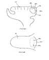
- a cavityis formed within the interior of the base of the tongue.
- the cavitymay be collapsed and permanently closed by suturing, stapling, gluing or otherwise closing the cavity.
- Systems according to the present inventiongenerally include an electrosurgical instrument having a shaft with proximal and distal ends, an electrode assembly at the distal end and one or more connectors coupling the electrode assembly to a source of high frequency electrical energy.
- the electrode assemblyincludes one or more active electrode(s) configured for tissue ablation, a return electrode spaced from the active electrode(s) on the instrument shaft and, optionally, a third, coagulation electrode spaced from the return electrode on the instrument shaft.
- the systemfurther includes a power source coupled to the electrodes on the instrument shaft for applying a high frequency voltage between the active and return electrodes, and between the coagulation and return electrodes, at the same time.
- the voltage applied between the coagulation and return electrodesis substantially lower than the voltage applied between the active and return electrodes to allow the former to coagulation severed blood vessels and heat tissue, while the latter ablates tissue.
- the active electrode(s)may comprise a single active electrode, or an electrode array, extending from an electrically insulating support member, typically made of an inorganic material such as ceramic, silicone or glass.
- the active electrodewill usually have a smaller exposed surface area than the return and coagulation electrodes such that the current densities are much higher at the active electrode than at the other electrodes.
- the return and coagulation electrodeshave relatively large, smooth surfaces extending around the instrument shaft to reduce current densities, thereby minimizing damage to adjacent tissue.
- the systemcomprises a voltage reduction element coupled between the power source and the coagulation electrode to reduce the voltage applied to the coagulation electrode.
- the voltage reduction elementwill typically comprise a passive element, such as a capacitor, resistor, inductor or the like.
- the power supplywill apply a voltage of about 150 to 350 volts rms between the active and return electrodes, and the voltage reduction element will reduce this voltage to about 20 to 90 volts rms to the coagulation electrode. In this manner, the voltage delivered to the coagulation electrode is below the threshold for ablation of tissue, but high enough to coagulation and heat the tissue.
- the apparatusmay further include a fluid delivery element for delivering electrically conducting fluid to the electrode terminal(s) and the target site.
- the fluid delivery elementmay be located on the instrument, e.g., a fluid lumen or tube, or it may be part of a separate instrument.
- an electrically conducting gel or spraysuch as a saline electrolyte or other conductive gel, may be applied to the electrode assembly or the target site.
- the apparatusmay not have a fluid delivery element.
- the electrically conducting fluidwill preferably generate a current flow path between the electrode terminal(s) and the return electrode(s).
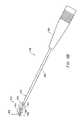
- FIG. 1is a perspective view of an electrosurgical system incorporating a power supply and an electrosurgical probe for tissue ablation, resection, incision, contraction and for vessel hemostasis according to the present invention
- FIG. 2is a side view of an electrosurgical probe according to the present invention.
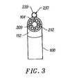
- FIG. 3is an end view of the probe of FIG. 2 ;
- FIG. 4is a cross sectional view of the electrosurgical probe of FIG. 1 ;
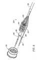
- FIG. 5is an exploded view of a proximal portion of the electrosurgical probe
- FIG. 6is an end view of an alternative electrosurgical probe incorporating an inner fluid lumen
- FIGS. 7A–7Care cross-sectional views of the distal portions of three different embodiments of an electrosurgical probe according to the present invention.
- FIGS. 8A and 8Bare cross-sectional and end views, respectively, of yet another electrosurgical probe incorporating flattened electrode terminals
- FIG. 9illustrates an electrosurgical probe with a 90° distal bend and a lateral fluid lumen
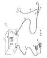
- FIG. 10illustrates an electrosurgical system with a separate fluid delivery instrument according to the present invention
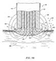
- FIGS. 11A and 11Billustrate a detailed view of the ablation of tissue according to the present invention
- FIGS. 12A–12Dillustrate three embodiments of electrosurgical probes specifically designed for treating obstructive sleep disorders
- FIG. 13illustrates an alternative embodiment of an electrosurgical probe for treating obstructive sleep disorders
- FIG. 14illustrates an electrosurgical system incorporating a dispersive return pad for monopolar and/or bipolar operations
- FIG. 15illustrates a catheter system for electrosurgical treatment of body structures within the head and neck according to the present invention
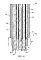
- FIG. 16is a cross-section view of a working end of a catheter according to one embodiment of the present invention.
- FIG. 17Ais a cross-section view of a working end of a catheter according to a second embodiment of the present invention.
- FIG. 17Bis an end view of the catheter of FIG. 17A ;
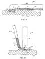
- FIG. 18illustrates a procedure for treating submucosal tissue according to the present invention
- FIG. 19is a top view of the tongue, illustrates a plurality of channels near the back of the tongue, generated with the techniques of the present invention
- FIG. 20is a side view of the tongue, illustrating a single channel
- FIG. 21is a detailed view of a single channel generated with the techniques of the present invention.
- FIG. 22schematically illustrates one embodiment of a power supply according to the present invention
- FIG. 23illustrates an electrosurgical system incorporating a plurality of active electrodes and associated current limiting elements
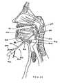
- FIG. 24illustrates a method for submucosal channeling with the probe of FIG. 12D ;
- FIG. 25illustrates another procedure according to the present invention for reducing the volume at the base of the tongue
- FIG. 26Ais a cross-sectional side view of the tongue illustrating the excavation or removal of tissue from within the base of the tongue as a result of the procedure of FIG. 25 ;
- FIG. 26Bis a top view of the tongue of FIG. 26A .
- FIG. 27is a side view of the tongue of FIG. 27 illustrating use of a suture to substantially collapse the area of excavation or removal of tissue within the tongue;
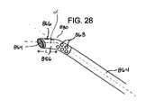
- FIG. 28illustrates the working end of a probe of an electrosurgical system according to an aspect of the present invention which is particularly suited for the procedure of FIG. 25 .
- test stripincludes a plurality of such test strips
- deviceincludes reference to one or more devices and equivalents thereof known to those skilled in the art, and so forth.
- the present inventionprovides systems and methods for selectively applying electrical energy to a target location within or on a patient's body, particularly including tissue in the head and neck, such as the ear, mouth, pharynx, larynx, esophagus, nasal cavity and sinuses. These procedures may be performed through the mouth or nose using speculae or gags, or using endoscopic techniques, such as functional endoscopic sinus surgery (FESS).
- FESSfunctional endoscopic sinus surgery
- These proceduresmay include the removal of swollen tissue, chronically-diseased inflamed and hypertrophic mucus linings, polyps and/or neoplasms from the various anatomical sinuses of the skull, the turbinates and nasal passages, in the tonsil, adenoid, epi-glottic and supra-glottic regions, and salivary glands, submucus resection of the nasal septum, excision of diseased tissue, trachea broncheal strictures and the like.
- the present inventionmay be useful for collagen shrinkage, ablation and/or hemostasis in procedures for treating snoring and obstructive sleep apnea (e.g., soft palate, such as the uvula, or tongue/pharynx stiffening, and midline glossectomies), for gross tissue removal, such as tonsillectomies, adenoidectomies, tracheal stenosis and vocal cord polyps and lesions, or for the resection or ablation of facial tumors or tumors within the mouth and pharynx, such as glossectomies, laryngectories, acoustic neuroma procedures and nasal ablation procedures.
- the present inventionis useful for procedures within the ear, such as stapedotomies, myringotomies, tympanostomies or the like.
- the present inventionis particularly useful for treating snoring and obstructive sleep apnea by creating channels within the tongue, tonsils, palate, or uvula, to stiffen the tissue within these structures.
- the remaining disclosurewill be directed specifically to the treatment of obstructive sleep disorders, but it will be appreciated that the system and method can be applied equally well to procedures involving other tissues of the body, as well as to other procedures including open procedures, intravascular procedures, urology, laparascopy, arthroscopy, thoracoscopy or other cardiac procedures, cosmetic surgery, orthopedics, gynecology, otorhinolaryngology, spinal and neurologic procedures, oncology and the like.
- the present inventionmay be applied to any type of electrosurgical device, including those using (RF) energy, the device is particularly useful in those devices using Coblation® technology (plasma assisted electrosurgical ablation devices).
- Coblation®requires application of a high frequency voltage difference between one or more active electrode(s) and one or more return electrode(s) to develop high electric field intensities in the vicinity of the target tissue.
- the high electric field intensitiesmay be generated by applying a high frequency voltage that is sufficient to vaporize an electrically conductive medium over at least a portion of the active electrode(s) in the region between the distal tip of the active electrode(s) and the target tissue.
- the electrically conductive mediummay be, for example, a liquid, gel or gas.
- Such electrically conductive mediuminclude isotonic saline, blood, extracelluar or intracellular fluid, delivered to, or already present at, the target site, or a viscous medium, such as a gel, applied to the target site.
- plasmasmay be formed by heating a gas and ionizing the gas by driving an electric current through it, or by shining radio waves into the gas. These methods of plasma formation give energy to free electrons in the plasma directly, and then electron-atom collisions liberate more electrons, and the process cascades until the desired degree of ionization is achieved.
- Plasma Physicsby R. J. Goldston and P. H. Rutherford of the Plasma Physics Laboratory of Princeton University (1995), the complete disclosure of which is incorporated herein by reference.
- the electron mean free pathincreases to enable subsequently injected electrons to cause impact ionization within the vapor layer).
- the ionic particles in the plasma layerhave sufficient energy, they accelerate towards the target tissue.
- Energy evolved by the energetic electronse.g., 3.5 eV to 5 eV
- the electronscan subsequently bombard a molecule and break its bonds, dissociating a molecule into free radicals, which then combine into final gaseous or liquid species.
- the electronscarry the electrical current or absorb the radio waves and, therefore, are hotter than the ions.
- the electronswhich are carried away from the tissue towards the return electrode, carry most of the plasma's heat with them, allowing the ions to break apart the tissue molecules in a substantially non-thermal manner.
- the target tissue structureis volumetrically removed through molecular disintegration of larger organic molecules into smaller molecules and/or atoms, such as hydrogen, oxygen, oxides of carbon, hydrocarbons and nitrogen compounds.
- This molecular disintegrationcompletely removes the tissue structure, as opposed to dehydrating the tissue material by the removal of liquid within the cells of the tissue and extracellular fluids, as is typically the case with electrosurgical desiccation and vaporization.
- electrosurgical desiccation and vaporizationA more detailed description of this phenomena can be found in commonly assigned U.S. Pat. No. 5,697,882 the complete disclosure of which is incorporated herein by reference.
- high frequency (RF) electrical energyis applied in an electrically conducting media environment to shrink or remove (i.e., resect, cut, or ablate) a tissue structure and to seal transected vessels within the region of the target tissue.
- Coblation technologyis also useful for sealing larger arterial vessels, e.g., on the order of about 1 mm in diameter.
- a high frequency power supplyhaving an ablation mode, wherein a first voltage is applied to an active electrode sufficient to effect molecular dissociation or disintegration of the tissue, and a coagulation mode, wherein a second, lower voltage is applied to an active electrode (either the same or a different electrode) sufficient to heat, shrink, and/or achieve hemostasis of severed vessels within the tissue.
- an electrosurgical instrumentis provided having one or more coagulation electrode(s) configured for sealing a severed vessel, such as an arterial vessel, and one or more active electrodes configured for either contracting the collagen fibers within the tissue or removing (ablating) the tissue, e.g., by applying sufficient energy to the tissue to effect molecular dissociation.
- a single voltagecan be applied to the tissue by the coagulation electrode(s), as well as to the active electrode(s) to ablate or shrink the tissue.
- the power supplyis combined with the coagulation instrument such that the coagulation electrode is used when the power supply is in the coagulation mode (low voltage), and the active electrode(s) are used when the power supply is in the ablation mode (higher voltage).
- the amount of energy produced by the Coblation® technologymay be varied by adjusting a variety of factors, such as: the number of active electrodes; electrode size and spacing; electrode surface area; asperities and sharp edges on the electrode surfaces; electrode materials; applied voltage and power; current limiting means, such as inductors; electrical conductivity of the medium in contact with the electrodes; density of the medium; and other factors. Accordingly, these factors can be manipulated to control the energy level of the excited electrons. Since different tissue structures have different molecular bonds, the Coblation® device may be configured to produce energy sufficient to break the molecular bonds of certain tissue but insufficient to break the molecular bonds of other tissue.
- fatty tissuee.g., adipose
- Coblation® technologygenerally does not ablate or remove such fatty tissue; however, it may be used to effectively ablate cells to release the inner fat content in a liquid form.
- factorsmay be changed such that these double bonds can also be broken in a similar fashion as the single bonds (e.g., increasing voltage or changing the electrode configuration to increase the current density at the electrode tips).
- U.S. Pat. Nos. 6,355,032, 6,149,120 and 6,296,136the complete disclosures of which are incorporated herein by reference.
- the active electrode(s) of a Coblation® deviceare preferably supported within or by an inorganic insulating support positioned near the distal end of the instrument shaft.
- the return electrodemay be located on the instrument shaft, on another instrument or on the external surface of the patient (i.e., a dispersive pad).
- the proximal end of the instrument(s)will include the appropriate electrical connections for coupling the return electrode(s) and the active electrode(s) to a high frequency power supply, such as an electrosurgical generator.
- Coblation®ablates tissue in a non-thermal manner
- surface temperature of the tissuehas been observed to be in the range of 40–70° C. Accordingly, it still may be desirable for the medical practitioner to have the ability to directly observe the temperature environment of the surgical site when using a Coblation® device.
- the invention described hereinmay be applied to any type of surgical instrument which generates heat either directly, or as a by-product of the procedure.
- the inventionmay be incorporated in devices using microwave energy, laser, UV light based, mechanical energy, etc. It is noted that the device has particular value in thermal electrosurgical devices.
- the present inventionapplies high frequency (RF) electrical energy in an electrically conducting media environment to remove (i.e., resect, cut or ablate) a tissue structure and to seal transected vessels within the region of the target tissue.
- RFhigh frequency
- the present inventionmay also be useful for sealing larger arterial vessels, e.g., on the order of about 1 mm in diameter.
- a high frequency power supplyis provided having an ablation mode, wherein a first voltage is applied to an electrode terminal sufficient to effect molecular dissociation or disintegration of the tissue, and a coagulation mode, wherein a second, lower voltage is applied to an electrode terminal (either the same or a different electrode) sufficient to achieve hemostasis of severed vessels within the tissue.
- an electrosurgical instrumenthaving one or more coagulation electrode(s) configured for sealing a severed vessel, such as an arterial vessel, and one or more electrode terminals configured for either contracting the collagen fibers within the tissue or removing (ablating) the tissue, e.g., by applying sufficient energy to the tissue to effect molecular dissociation.
- the coagulation electrode(s)may be configured such that a single voltage can be applied to coagulate with the coagulation electrode(s), and to ablate with the electrode terminal(s).
- the power supplyis combined with the coagulation instrument such that the coagulation electrode is used when the power supply is in the coagulation mode (low voltage), and the electrode terminal(s) are used when the power supply is in the ablation mode (higher voltage).
- one or more electrode terminalsare brought into close proximity to tissue at a target site, and the power supply is activated in the ablation mode such that sufficient voltage is applied between the electrode terminals and the return electrode to volumetrically remove the tissue through molecular dissociation, as described below.
- the power supplyis activated in the ablation mode such that sufficient voltage is applied between the electrode terminals and the return electrode to volumetrically remove the tissue through molecular dissociation, as described below.
- vessels within the tissuewill be severed. Smaller vessels will be automatically sealed with the system and method of the present invention. Larger vessels, and those with a higher flow rate, such as arterial vessels, may not be automatically sealed in the ablation mode. In these cases, the severed vessels may be sealed by activating a control (e.g., a foot pedal) to reduce the voltage of the power supply into the coagulation mode.
- a controle.g., a foot pedal
- the electrode terminalsmay be pressed against the severed vessel to provide sealing and/or coagulation of the vessel.
- a coagulation electrode located on the same or a different instrumentmay be pressed against the severed vessel.
- the tissueis damaged in a thermal heating mode to create necrosed or scarred tissue at the tissue surface.
- the high frequency voltage in the thermal heating modeis below the threshold of ablation as described above, but sufficient to cause some thermal damage to the tissue immediately surrounding the electrodes without vaporizing or otherwise debulking this tissue.
- a tissue temperaturein the range of about 60° C. to 100° C. to a depth of about 0.2 to 5 mm, usually about 1 to 2 mm.
- the voltage required for this thermal damagewill partly depend on the electrode configurations, the conductivity of the tissue and the area immediately surrounding the electrodes, the time period in which the voltage is applied and the depth of tissue damage desired.
- the voltage level for thermal heatingwill usually be in the range of about 20 to 300 volts rms, preferably about 60 to 200 volts rms.
- the peak-to-peak voltages for thermal heating with a square wave form having a crest factor of about 2are typically in the range of about 40 to 600 volts peak-to-peak, preferably about 120 to 400 volts peak-to-peak. The higher the voltage is within this range, the less time required. If the voltage is too high, however, the surface tissue may be vaporized, debulked or ablated, which is undesirable.
- the present inventionis also useful for removing or ablating tissue around nerves, such as spinal, peripheral or cranial nerves, e.g., optic nerve, facial nerves, vestibulocochlear nerves and the like.
- nervessuch as spinal, peripheral or cranial nerves, e.g., optic nerve, facial nerves, vestibulocochlear nerves and the like.
- One of the significant drawbacks with the prior art microdebriders, conventional electrosurgical devices and lasersis that these devices do not differentiate between the target tissue and the surrounding nerves or bone. Therefore, the surgeon must be extremely careful during these procedures to avoid damage to the bone or nerves within and around the target site.
- the Coblation® process for removing tissueresults in extremely small depths of collateral tissue damage as discussed above. This allows the surgeon to remove tissue close to a nerve without causing collateral damage to the nerve fibers.
- Nervesusually comprise a connective tissue sheath, or epineurium, enclosing the bundles of nerve fibers, each bundle being surrounded by its own sheath of connective tissue (the perineurium) to protect these nerve fibers.
- the outer protective tissue sheath or epineuriumtypically comprises a fatty tissue (e.g., adipose tissue) having substantially different electrical properties than the normal target tissue, such as the turbinates, polyps, mucus tissue or the like, that are, for example, removed from the nose during sinus procedures.
- the system of the present inventionmeasures the electrical properties of the tissue at the tip of the probe with one or more electrode terminal(s).
- These electrical propertiesmay include electrical conductivity at one, several or a range of frequencies (e.g., in the range from 1 kHz to 100 MHz), dielectric constant, capacitance or combinations of these.
- an audible signalmay be produced when the sensing electrode(s) at the tip of the probe detects the fatty tissue surrounding a nerve, or direct feedback control can be provided to only supply power to the electrode terminal(s) either individually or to the complete array of electrodes, if and when the tissue encountered at the tip or working end of the probe is normal tissue based on the measured electrical properties.
- the current limiting elementsare configured such that the electrode terminals will shut down or turn off when the electrical impedance reaches a threshold level.
- a threshold levelis set to the impedance of the fatty tissue surrounding nerves, the electrode terminals will shut off whenever they come in contact with, or in close proximity to, nerves. Meanwhile, the other electrode terminals, which are in contact with or in close proximity to tissue, will continue to conduct electric current to the return electrode.
- the present inventionis capable of volumetrically removing tissue closely adjacent to nerves without impairment the function of the nerves, and without significantly damaging the tissue of the epineurium.
- One of the significant drawbacks with the prior art microdebriders, conventional electrosurgical devices and lasersis that these devices do not differentiate between the target tissue and the surrounding nerves or bone. Therefore, the surgeon must be extremely careful during these procedures to avoid damage to the bone or nerves within and around the nasal cavity.
- the Coblation® process for removing tissueresults in extremely small depths of collateral tissue damage as discussed above. This allows the surgeon to remove tissue close to a nerve without causing collateral damage to the nerve fibers.
- the Coblation® mechanism of the present inventioncan be manipulated to ablate or remove certain tissue structures, while having little effect on other tissue structures.
- the present inventionuses a technique of vaporizing electrically conductive fluid to form a plasma layer or pocket around the electrode terminal(s), and then inducing the discharge of energy from this plasma or vapor layer to break the molecular bonds of the tissue structure. Based on initial experiments, applicants believe that the free electrons within the ionized vapor layer are accelerated in the high electric fields near the electrode tip(s).
- the electron mean free pathincreases to enable subsequently injected electrons to cause impact ionization within these regions of low density (i.e., vapor layers or bubbles).
- Energy evolved by the energetic electronse.g., 4 to 5 eV
- the energy evolved by the energetic electronsmay be varied by adjusting a variety of factors, such as: the number of electrode terminals; electrode size and spacing; electrode surface area; asperities and sharp edges on the electrode surfaces; electrode materials; applied voltage and power; current limiting means, such as inductors; electrical conductivity of the fluid in contact with the electrodes; density of the fluid; and other factors. Accordingly, these factors can be manipulated to control the energy level of the excited electrons. Since different tissue structures have different molecular bonds, the present invention can be configured to break the molecular bonds of certain tissue, while having too low an energy to break the molecular bonds of other tissue.
- fatty tissuee.g., adipose
- fatty tissuee.g., adipose
- the present inventionin its current configuration generally does not ablate or remove such fatty tissue.
- factorsmay be changed such that these double bonds can also be broken in a similar fashion as the single bonds (e.g., increasing voltage or changing the electrode configuration to increase the current density at the electrode tips).
- the present inventionalso provides systems, apparatus and methods for selectively removing tumors, e.g., facial tumors, or other undesirable body structures while minimizing the spread of viable cells from the tumor.
- Conventional techniques for removing such tumorsgenerally result in the production of smoke in the surgical setting, termed an electrosurgical or laser plume, which can spread intact, viable bacterial or viral particles from the tumor or lesion to the surgical team or to other portions of the patient's body.
- This potential spread of viable cells or particleshas resulted in increased concerns over the proliferation of certain debilitating and fatal diseases, such as hepatitis, herpes, HIV and papillomavirus.
- high frequency voltageis applied between the electrode terminal(s) and one or more return electrode(s) to volumetrically remove at least a portion of the tissue cells in the tumor through the dissociation or disintegration of organic molecules into non-viable atoms and molecules.
- the present inventionconverts the solid tissue cells into non-condensable gases that are no longer intact or viable, and thus, not capable of spreading viable tumor particles to other portions of the patient's brain or to the surgical staff.
- the high frequency voltageis preferably selected to effect controlled removal of these tissue cells while minimizing substantial tissue necrosis to surrounding or underlying tissue.
- the RF energyheats the tissue directly by virtue of the electrical current flow therethrough, and/or indirectly through the exposure of the tissue to fluid heated by RF energy, to elevate the tissue temperature from normal body temperatures (e.g., 37° C.) to temperatures in the range of 45° C. to 90° C., preferably in the range from about 60° C. to 70° C.
- Thermal shrinkage of collagen fibersoccurs within a small temperature range which, for mammalian collagen is in the range from 60° C. to 70° C.
- the preferred depth of heating to effect the shrinkage of collagen in the heated regioni.e., the depth to which the tissue is elevated to temperatures between 60° C. to 70° C.
- the depth of heatingis usually in the range from 0 to 3.5 mm. In the case of collagen within the soft palate or uvula, the depth of heating is preferably in the range from about 0.5 to about 3.5 mm.
- the electrosurgical instrumentwill comprise a shaft or a handpiece having a proximal end and a distal end which supports one or more electrode terminal(s).
- the shaft or handpiecemay assume a wide variety of configurations, with the primary purpose being to mechanically support the active electrode and permit the treating physician to manipulate the electrode from a proximal end of the shaft.
- the shaftmay be rigid or flexible, with flexible shafts optionally being combined with a generally rigid external tube for mechanical support. Flexible shafts may be combined with pull wires, shape memory actuators, and other known mechanisms for effecting selective deflection of the distal end of the shaft to facilitate positioning of the electrode array.
- the shaftwill usually include a plurality of wires or other conductive elements running axially therethrough to permit connection of the electrode array to a connector at the proximal end of the shaft.
- the shaftwill have a suitable diameter and length to allow the surgeon to reach the target by delivering the instrument shaft through the patient's mouth or another opening.
- the shaftwill usually have a length in the range of about 5–25 cm, and a diameter in the range of about 0.5 to 5 mm.
- the distal end portion of the shaftwill usually have a diameter less than 3 mm, preferably less than about 1.0 mm.
- the shaftwill be suitably designed to access the larynx.
- the shaftmay be flexible, or have a distal bend to accommodate the bend in the patient's throat.
- the shaftmay be a rigid shaft having a specifically designed bend to correspond with the geometry of the mouth and throat, or it may have a flexible distal end, or it may be part of a catheter.
- the shaftmay also be introduced through rigid or flexible endoscopes.
- the electrosurgical instrumentmay also be a catheter that is delivered percutaneously and/or endoluminally into the patient by insertion through a conventional or specialized guide catheter, or the invention may include a catheter having an active electrode or electrode array integral with its distal end.
- the catheter shaftmay be rigid or flexible, with flexible shafts optionally being combined with a generally rigid external tube for mechanical support. Flexible shafts may be combined with pull wires, shape memory actuators, and other known mechanisms for effecting selective deflection of the distal end of the shaft to facilitate positioning of the electrode or electrode array.
- the catheter shaftwill usually include one or more wires or other conductive elements running axially therethrough to permit connection of the electrode or electrode array and the return electrode to a connector at the proximal end of the catheter shaft.
- the catheter shaftmay include a guide wire for guiding the catheter to the target site, or the catheter may comprise a steerable guide catheter.
- the cathetermay also include a substantially rigid distal end portion to increase the torque control of the distal end portion as the catheter is advanced further into the patient's body.
- the electrode terminal(s)are preferably supported within or by an inorganic insulating support positioned near the distal end of the instrument shaft.
- the return electrodemay be located on the instrument shaft, on another instrument or on the external surface of the patient (i.e., a dispersive pad).
- a dispersive padlocated on the instrument shaft, on another instrument or on the external surface of the patient (i.e., a dispersive pad).
- the return electrodeis preferably either integrated with the instrument body, or another instrument located in close proximity thereto.
- the proximal end of the instrument(s)will include the appropriate electrical connections for coupling the return electrode(s) and the electrode terminal(s) to a high frequency power supply, such as an electrosurgical generator.
- the return electrodeis typically spaced proximally from the active electrode(s) a suitable distance to avoid electrical shorting between the active and return electrodes in the presence of electrically conductive fluid.
- the distal edge of the exposed surface of the return electrodeis spaced about 0.5 to 25 mm from proximal edge of the exposed surface of the active electrode(s), preferably about 1.0 to 5.0 mm.
- this distancemay vary with different voltage ranges, conductive fluids, and depending on the proximity of tissue structures to active and return electrodes.
- the return electrodewill typically have an exposed length in the range of about 1 to 20 mm.
- the current flow path between the electrode terminals and the return electrode(s)may be generated by submerging the tissue site in an electrical conducting fluid (e.g., within a viscous fluid, such as an electrically conductive gel) or by directing an electrically conducting fluid along a fluid path to the target site (i.e., a liquid, such as isotonic saline, hypotonic saline or a gas, such as argon).
- the conductive gelmay also be delivered to the target site to achieve a slower more controlled delivery rate of conductive fluid.
- the viscous nature of the gelmay allow the surgeon to more easily contain the gel around the target site (e.g., rather than attempting to contain isotonic saline).
- a liquid electrically conductive fluide.g., isotonic saline
- a liquid electrically conductive fluidmay be used to concurrently “bathe” the target tissue surface to provide an additional means for removing any tissue, and to cool the region of the target tissue ablated in the previous moment.
- the power supplymay include a fluid interlock for interrupting power to the electrode terminal(s) when there is insufficient conductive fluid around the electrode terminal(s). This ensures that the instrument will not be activated when conductive fluid is not present, minimizing the tissue damage that may otherwise occur.
- a fluid interlockcan be found in commonly assigned, co-pending U.S. Pat. No. 6,235,020, filed Apr. 10, 1998, the complete disclosure of which is incorporated herein by reference.
- the system of the present inventionmay include one or more suction lumen(s) in the instrument, or on another instrument, coupled to a suitable vacuum source for aspirating fluids from the target site.
- the inventionmay include one or more aspiration electrode(s) coupled to the distal end of the suction lumen for ablating, or at least reducing the volume of, non-ablated tissue fragments that are aspirated into the lumen.
- the aspiration electrode(s)function mainly to inhibit clogging of the lumen that may otherwise occur as larger tissue fragments are drawn therein.
- the aspiration electrode(s)may be different from the ablation electrode terminal(s), or the same electrode(s) may serve both functions.
- suctionit may be desirable to contain the excess electrically conductive fluid, tissue fragments and/or gaseous products of ablation at or near the target site with a containment apparatus, such as a basket, retractable sheath or the like.
- a containment apparatussuch as a basket, retractable sheath or the like.
- This embodimenthas the advantage of ensuring that the conductive fluid, tissue fragments or ablation products do not flow through the patient's vasculature or into other portions of the body.
- the present inventionmay use a single active electrode terminal or an array of electrode terminals spaced around the distal surface of a catheter or probe.
- the electrode arrayusually includes a plurality of independently current-limited and/or power-controlled electrode terminals to apply electrical energy selectively to the target tissue while limiting the unwanted application of electrical energy to the surrounding tissue and environment resulting from power dissipation into surrounding electrically conductive fluids, such as blood, normal saline, and the like.
- the electrode terminalsmay be independently current-limited by isolating the terminals from each other and connecting each terminal to a separate power source that is isolated from the other electrode terminals.
- the electrode terminalsmay be connected to each other at either the proximal or distal ends of the catheter to form a single wire that couples to a power source.
- each individual electrode terminal in the electrode arrayis electrically insulated from all other electrode terminals in the array within said instrument and is connected to a power source which is isolated from each of the other electrode terminals in the array or to circuitry which limits or interrupts current flow to the electrode terminal when low resistivity material (e.g., blood, electrically conductive saline irrigant or electrically conductive gel) causes a lower impedance path between the return electrode and the individual electrode terminal.
- the isolated power sources for each individual electrode terminalmay be separate power supply circuits having internal impedance characteristics which limit power to the associated electrode terminal when a low impedance return path is encountered.
- the isolated power sourcemay be a user selectable constant current source.
- a single power sourcemay be connected to each of the electrode terminals through independently actuatable switches, or by independent current limiting elements, such as inductors, capacitors, resistors and/or combinations thereof.
- the current limiting elementsmay be provided in the instrument, connectors, cable, controller or along the conductive path from the controller to the distal tip of the instrument.
- the resistance and/or capacitancemay occur on the surface of the active electrode terminal(s) due to oxide layers which form selected electrode terminals (e.g., titanium or a resistive coating on the surface of metal, such as platinum).
- the tip region of the instrumentmay comprise many independent electrode terminals designed to deliver electrical energy in the vicinity of the tip.
- the selective application of electrical energy to the conductive fluidis achieved by connecting each individual electrode terminal and the return electrode to a power source having independently controlled or current limited channels.
- the return electrode(s)may comprise a single tubular member of conductive material proximal to the electrode array at the tip which also serves as a conduit for the supply of the electrically conducting fluid between the active and return electrodes.
- the instrumentmay comprise an array of return electrodes at the distal tip of the instrument (together with the active electrodes) to maintain the electric current at the tip.
- the application of high frequency voltage between the return electrode(s) and the electrode arrayresults in the generation of high electric field intensities at the distal tips of the electrode terminals with conduction of high frequency current from each individual electrode terminal to the return electrode.
- the current flow from each individual electrode terminal to the return electrode(s)is controlled by either active or passive means, or a combination thereof, to deliver electrical energy to the surrounding conductive fluid while minimizing energy delivery to surrounding (non-target) tissue.
- the application of a high frequency voltage between the return electrode(s) and the electrode terminal(s) for appropriate time intervalseffects cutting, removing, ablating, shaping, contracting or otherwise modifying the target tissue.
- the tissue volume over which energy is dissipatedi.e., a high current density exists
- the tissue volume over which energy is dissipatedmay be more precisely controlled, for example, by the use of a multiplicity of small electrode terminals whose effective diameters or principal dimensions range from about 10 mm to 0.01 mm, preferably from about 2 mm to 0.05 mm, and more preferably from about 1 mm to 0.1 mm.
- electrode areas for both circular and non-circular terminalswill have a contact area (per electrode terminal) below 50 mm 2 for electrode arrays and as large as 75 mm 2 for single electrode embodiments.
- the contact area of each electrode terminalis typically in the range from 0.0001 mm 2 to 1 mm 2 , and more preferably from 0.001 mm 2 to 0.5 mm 2 .
- the circumscribed area of the electrode array or electrode terminalis in the range from 0.25 mm 2 to 75 mm 2 , preferably from 0.5 mm 2 to 40 mm 2 .
- the arraywill usually include at least two isolated electrode terminals, often at least five electrode terminals, often greater than 10 electrode terminals and even 50 or more electrode terminals, disposed over the distal contact surfaces on the shaft.
- the use of small diameter electrode terminalsincreases the electric field intensity and reduces the extent or depth of tissue heating as a consequence of the divergence of current flux lines which emanate from the exposed surface of each electrode terminal.
- the area of the tissue treatment surfacecan vary widely, and the tissue treatment surface can assume a variety of geometries, with particular areas and geometries being selected for specific applications.
- the geometriescan be planar, concave, convex, hemispherical, conical, linear “in-line” array or virtually any other regular or irregular shape.
- the active electrode(s) or electrode terminal(s)will be formed at the distal tip of the electrosurgical instrument shaft, frequently being planar, disk-shaped, or hemispherical surfaces for use in reshaping procedures or being linear arrays for use in cutting.
- the active electrode(s)may be formed on lateral surfaces of the electrosurgical instrument shaft (e.g., in the manner of a spatula), facilitating access to certain body structures in endoscopic procedures.
- the electrode support and the fluid outletmay be recessed from an outer surface of the instrument or handpiece to confine the electrically conductive fluid to the region immediately surrounding the electrode support.
- the shaftmay be shaped so as to form a cavity around the electrode support and the fluid outlet. This helps to assure that the electrically conductive fluid will remain in contact with the electrode terminal(s) and the return electrode(s) to maintain the conductive path therebetween. In addition, this will help to maintain a vapor layer and subsequent plasma layer between the electrode terminal(s) and the tissue at the treatment site throughout the procedure, which reduces the thermal damage that might otherwise occur if the vapor layer were extinguished due to a lack of conductive fluid. Provision of the electrically conductive fluid around the target site also helps to maintain the tissue temperature at desired levels.
- the active electrodesare spaced from the tissue a sufficient distance to minimize or avoid contact between the tissue and the vapor layer formed around the active electrodes.
- contact between the heated electrons in the vapor layer and the tissueis minimized as these electrons travel from the vapor layer back through the conductive fluid to the return electrode.
- the ions within the plasmawill have sufficient energy, under certain conditions such as higher voltage levels, to accelerate beyond the vapor layer to the tissue.
- the tissue bondsare dissociated or broken as in previous embodiments, while minimizing the electron flow, and thus the thermal energy, in contact with the tissue.
- the electrically conducting fluidshould have a threshold conductivity to provide a suitable conductive path between the return electrode and the electrode terminal(s).
- the electrical conductivity of the fluid(in units of milliSiemans per centimeter or mS/cm) will usually be greater than 0.2 mS/cm, preferably will be greater than 2 mS/cm and more preferably greater than 10 mS/cm.
- the electrically conductive fluidis isotonic saline, which has a conductivity of about 17 mS/cm. Applicant has found that a more conductive fluid, or one with a higher ionic concentration, will usually provide a more aggressive ablation rate.
- a saline solution with higher levels of sodium chloride than conventional saline(which is on the order of about 0.9% sodium chloride) e.g., on the order of greater than 1% or between about 3% and 20%, may be desirable.
- the inventionmay be used with different types of conductive fluids that increase the power of the plasma layer by, for example, increasing the quantity of ions in the plasma, or by providing ions that have higher energy levels than sodium ions.
- the present inventionmay be used with elements other than sodium, such as potassium, magnesium, calcium and other metals near the left end of the periodic chart.
- other electronegative elementsmay be used in place of chlorine, such as fluorine.
- the voltage difference applied between the return electrode(s) and the electrode terminal(s)will be at high or radio frequency, typically between about 5 kHz and 20 MHz, usually being between about 30 kHz and 2.5 MHz, preferably being between about 50 kHz and 500 kHz, often less than 350 kHz, and often between about 100 kHz and 200 kHz.
- a frequency of about 100 kHzis useful because the tissue impedance is much greater at this frequency.
- higher frequenciesmay be desirable (e.g., 400–600 kHz) to minimize low frequency current flow into the heart or the nerves of the head and neck.
- the RMS (root mean square) voltage appliedwill usually be in the range from about 5 volts to 1000 volts, preferably being in the range from about 10 volts to 500 volts, often between about 150 to 400 volts depending on the electrode terminal size, the operating frequency and the operation mode of the particular procedure or desired effect on the tissue (i.e., contraction, coagulation, cutting or ablation).
- the peak-to-peak voltage for ablation or cutting with a square wave formwill be in the range of 10 to 2000 volts and preferably in the range of 100 to 1800 volts and more preferably in the range of about 300 to 1500 volts, often in the range of about 300 to 800 volts peak to peak (again, depending on the electrode size, number of electrons, the operating frequency and the operation mode).
- Lower peak-to-peak voltageswill be used for tissue coagulation, thermal heating of tissue, or collagen contraction and will typically be in the range from 50 to 1500, preferably 100 to 1000 and more preferably 120 to 400 volts peak-to-peak (again, these values are computed using a square wave form).
- Peak-to-peak voltagese.g., greater than about 800 volts peak-to-peak, may be desirable for ablation of harder material, such as bone, depending on other factors, such as the electrode geometries and the composition of the conductive fluid.
- the voltageis usually delivered in a series of voltage pulses or alternating current of time varying voltage amplitude with a sufficiently high frequency (e.g., on the order of 5 kHz to 20 MHz) such that the voltage is effectively applied continuously (as compared with e.g., lasers claiming small depths of necrosis, which are generally pulsed about 10 to 20 Hz).
- the duty cyclei.e., cumulative time in any one-second interval that energy is applied
- the preferred power source of the present inventiondelivers a high frequency current selectable to generate average power levels ranging from several milliwatts to tens of watts per electrode, depending on the volume of target tissue being heated, and/or the maximum allowed temperature selected for the instrument tip.
- the power sourceallows the user to select the voltage level according to the specific requirements of a particular neurosurgery procedure, cardiac surgery, arthroscopic surgery, dermatological procedure, ophthalmic procedures, open surgery or other endoscopic surgery procedure.
- the power sourcemay have an additional filter, for filtering leakage voltages at frequencies below 100 kHz, particularly voltages around 60 kHz.
- a power source having a higher operating frequencye.g., 300 to 600 kHz may be used in certain procedures in which stray low frequency currents may be problematic.
- a description of one suitable power sourcecan be found in co-pending patent application Ser. Nos. 09/058,571 and 09/058,336, filed Apr. 10, 1998, the complete disclosure of both applications are incorporated herein by reference for all purposes.
- the power sourcemay be current limited or otherwise controlled so that undesired heating of the target tissue or surrounding (non-target) tissue does not occur.
- current limiting inductorsare placed in series with each independent electrode terminal, where the inductance of the inductor is in the range of 10 uH to 50,000 uH, depending on the electrical properties of the target tissue, the desired tissue heating rate and the operating frequency.
- capacitor-inductor (LC) circuit structuresmay be employed, as described previously in U.S. Pat. No. 5,697,909, the complete disclosure of which is incorporated herein by reference. Additionally, current limiting resistors may be selected.
- these resistorswill have a large positive temperature coefficient of resistance so that, as the current level begins to rise for any individual electrode terminal in contact with a low resistance medium (e.g., saline irrigant or blood), the resistance of the current limiting resistor increases significantly, thereby minimizing the power delivery from said electrode terminal into the low resistance medium (e.g., saline irrigant or blood).
- a low resistance mediume.g., saline irrigant or blood
- the inventionis not limited to electrically isolated electrode terminals, or even to a plurality of electrode terminals.
- the array of active electrode terminalsmay be connected to a single lead that extends through the catheter shaft to a power source of high frequency current.
- the instrumentmay incorporate a single electrode that extends directly through the catheter shaft or is connected to a single lead that extends to the power source.
- the active electrode(s)may have ball shapes (e.g., for tissue vaporization and desiccation), twizzle shapes (for vaporization and needle-like cutting), spring shapes (for rapid tissue debulking and desiccation), twisted metal shapes, annular or solid tube shapes or the like.
- the electrode(s)may comprise a plurality of filaments, rigid or flexible brush electrode(s) (for debulking a tumor, such as a fibroid, bladder tumor or a prostate adenoma), side-effect brush electrode(s) on a lateral surface of the shaft, coiled electrode(s) or the like.
- an electrosurgical catheter or probecomprises a single active electrode terminal that extends from an insulating member, e.g., ceramic, at the distal end of the shaft.
- the insulating memberis preferably a tubular structure that separates the active electrode terminal from a tubular or annular return electrode positioned proximal to the insulating member and the active electrode.
- the catheter or probeincludes a single active electrode that can be rotated relative to the rest of the catheter body, or the entire catheter may be rotated related to the lead. The single active electrode can be positioned adjacent the abnormal tissue and energized and rotated as appropriate to remove this tissue.
- the current flow path between the electrode terminal(s) and the return electrode(s)may be generated by submerging the tissue site in an electrical conducting media (e.g., within a viscous fluid, such as an electrically conductive gel) or by directing an electrically conducting fluid along a fluid path to the target site (i.e., a liquid, such as isotonic saline, or a gas, such as argon).
- an electrically conducting fluidalong a fluid path to the target site (i.e., a liquid, such as isotonic saline, or a gas, such as argon).
- Electrosurgical system 11generally comprises an electrosurgical handpiece or probe 10 connected to a power supply 28 for providing high frequency voltage to a target site and a fluid source 21 for supplying electrically conducting fluid 50 to probe 10 .
- electrosurgical system 11may include an endoscope (not shown) with a fiber optic head light for viewing the surgical site, particularly in sinus procedures or procedures in the ear or the back of the mouth.
- the endoscopemay be integral with probe 10 , or it may be part of a separate instrument.
- the system 11may also include a vacuum source (not shown) for coupling to a suction lumen or tube 205 (see FIG. 2 ) in the probe 10 for aspirating the target site.
- probe 10generally includes a proximal handle 19 and an elongate shaft 18 having an array 12 of electrode terminals 58 at its distal end.
- a connecting cable 34has a connector 26 for electrically coupling the electrode terminals 58 to power supply 28 .
- the electrode terminals 58are electrically isolated from each other and each of the terminals 58 is connected to an active or passive control network within power supply 28 by means of a plurality of individually insulated conductors (not shown).
- a fluid supply tube 15is connected to a fluid tube 14 of probe 10 for supplying electrically conducting fluid 50 to the target site. Fluid supply tube 15 may be connected to a suitable pump (not shown), if desired.
- Power supply 28has an operator controllable voltage level adjustment 30 to change the applied voltage level, which is observable at a voltage level display 32 .
- Power supply 28also includes first, second and third foot pedals 37 , 38 , 39 and a cable 36 which is removably coupled to power supply 28 .
- the foot pedals 37 , 38 , 39allow the surgeon to remotely adjust the energy level applied to electrode terminals 58 .
- first foot pedal 37is used to place the power supply into the “ablation” mode and second foot pedal 38 places power supply 28 into the “sub-ablation” mode (e.g., coagulation or contraction of tissue).
- the third foot pedal 39allows the user to adjust the voltage level within the “ablation” mode.
- a sufficient voltageis applied to the electrode terminals to establish the requisite conditions for molecular dissociation of the tissue (i.e., vaporizing a portion of the electrically conductive fluid, ionizing charged particles within the vapor layer and accelerating these charged particles against the tissue).
- the requisite voltage level for ablationwill vary depending on the number, size, shape and spacing of the electrodes, the distance in which the electrodes extend from the support member, etc.
- the power supply 28applies a low enough voltage to the electrode terminals to avoid vaporization of the electrically conductive fluid and subsequent molecular dissociation of the tissue.
- the surgeonmay automatically toggle the power supply between the ablation and sub-ablation modes by alternatively stepping on foot pedals 37 , 38 , respectively. In some embodiments, this allows the surgeon to quickly move between coagulation/thermal heating and ablation in situ, without having to remove his/her concentration from the surgical field or without having to request an assistant to switch the power supply.
- the probetypically will simultaneously seal and/or coagulation small severed vessels within the tissue.
- the surgeoncan simply step on foot pedal 38 , automatically lowering the voltage level below the threshold level for ablation, and apply sufficient pressure onto the severed vessel for a sufficient period of time to seal and/or coagulate the vessel. After this is completed, the surgeon may quickly move back into the ablation mode by stepping on foot pedal 37 .
- the high frequency power supply of the present inventionis configured to apply a high frequency voltage of about 10 to 500 volts RMS between one or more electrode terminals (and/or coagulation electrode) and one or more return electrodes.
- the power supplyapplies about 70–350 volts RMS in the ablation mode and about 20 to 90 volts in a subablation mode, preferably 45 to 70 volts in the subablation mode (these values will, of course, vary depending on the probe configuration attached to the power supply and the desired mode of operation).
- the preferred power source of the present inventiondelivers a high frequency current selectable to generate average power levels ranging from several milliwatts to tens of watts per electrode, depending on the volume of target tissue being heated, and/or the maximum allowed temperature selected for the probe tip.
- the power sourceallows the user to select the voltage level according to the specific requirements of a particular procedure, e.g., arthroscopic surgery, dermatological procedure, ophthalmic procedures, open surgery or other endoscopic surgery procedure.
- the power supplygenerally comprises a radio frequency (RF) power oscillator 100 having output connections for coupling via a power output signal 102 to the load impedance, which is represented by the electrode assembly when the electrosurgical probe is in use.
- RFradio frequency
- the RF oscillatoroperates at about 100 kHz.
- the RF oscillatoris not limited to this frequency and may operate at frequencies of about 300 kHz to 600 kHz. In particular, for cardiac applications, the RF oscillator will preferably operate in the range of about 400 kHz to about 600 kHz.
- the RF oscillatorwill generally supply a square wave signal with a crest factor of about 1 to 2.
- this signalmay be a sine wave signal or other suitable wave signal depending on the application and other factors, such as the voltage applied, the number and geometry of the electrodes, etc.
- the power output signal 102is designed to incur minimal voltage decrease (i.e., sag) under load. This improves the applied voltage to the electrode terminals and the return electrode, which improves the rate of volumetric removal (ablation) of tissue.
- the switching power supply 140allows the generator to achieve high peak power output without the large size and weight of a bulky transformer.
- the architecture of the switching power supplyalso has been designed to reduce electromagnetic noise such that U.S. and foreign EMI requirements are met. This architecture comprises a zero voltage switching or crossing, which causes the transistors to turn ON and OFF when the voltage is zero. Therefore, the electromagnetic noise produced by the transistors switching is vastly reduced.
- the switching power supply 104operates at about 100 kHz.
- the controller 106may be a microprocessor or an integrated circuit.
- the power supplymay also include one or more current sensors 112 for detecting the output current.
- the power supplyis preferably housed within a metal casing which provides a durable enclosure for the electrical components therein.
- the metal casingreduces the electromagnetic noise generated within the power supply because the grounded metal casing functions as a “Faraday shield”, thereby shielding the environment from internal sources of electromagnetic noise.
- the power supplygenerally comprises a main or mother board containing generic electrical components required for many different surgical procedures (e.g., arthroscopy, urology, general surgery, dermatology, neurosurgery, etc.), and a daughter board containing application specific current-limiting circuitry (e.g., inductors, resistors, capacitors and the like).
- the daughter boardis coupled to the mother board by a detachable multi-pin connector to allow convenient conversion of the power supply to, e.g., applications requiring a different current limiting circuit design.
- the daughter boardpreferably comprises a plurality of inductors of about 200 to 400 microhenries, usually about 300 microhenries, for each of the channels supplying current to the electrode terminals 02 (see FIG. 2 ).
- current limiting inductorsare placed in series with each independent electrode terminal, where the inductance of the inductor is in the range of 10 uH to 50,000 uH, depending on the electrical properties of the target tissue, the desired tissue heating rate and the operating frequency.
- capacitor-inductor (LC) circuit structuresmay be employed, as described previously in co-pending PCT application No. PCT/US94/05168, the complete disclosure of which is incorporated herein by reference. Additionally, current limiting resistors may be selected.
- these resistorswill have a large positive temperature coefficient of resistance so that, as the current level begins to rise for any individual electrode terminal in contact with a low resistance medium (e.g., saline irrigant or conductive gel), the resistance of the current limiting resistor increases significantly, thereby minimizing the power delivery from said electrode terminal into the low resistance medium (e.g., saline irrigant or conductive gel).
- Power output signalmay also be coupled to a plurality of current limiting elements 96 , which are preferably located on the daughter board since the current limiting elements may vary depending on the application.
- FIGS. 2–4illustrate an exemplary electrosurgical probe 20 constructed according to the principles of the present invention.
- probe 90generally includes an elongated shaft 100 which may be flexible or rigid, a handle 204 coupled to the proximal end of shaft 100 and an electrode support member 102 coupled to the distal end of shaft 100 .
- Shaft 100preferably comprises an electrically conducting material, usually metal, which is selected from the group comprising tungsten, stainless steel alloys, platinum or its alloys, titanium or its alloys, molybdenum or its alloys, and nickel or its alloys.
- shaft 100includes an electrically insulating jacket 108 , which is typically formed as one or more electrically insulating sheaths or coatings, such as polytetrafluoroethylene, polyimide, and the like.
- electrically insulating jacket 108is typically formed as one or more electrically insulating sheaths or coatings, such as polytetrafluoroethylene, polyimide, and the like.
- the provision of the electrically insulating jacket over the shaftprevents direct electrical contact between these metal elements and any adjacent body structure or the surgeon. Such direct electrical contact between a body structure (e.g., tendon) and an exposed electrode could result in unwanted heating and necrosis of the structure at the point of contact causing necrosis.
- Handle 204typically comprises a plastic material that is easily molded into a suitable shape for handling by the surgeon. Handle 204 defines an inner cavity (not shown) that houses the electrical connections 250 ( FIG. 4 ), and provides a suitable interface for connection to an electrical connecting cable 22 (see FIG. 1 ). Electrode support member 102 extends from the distal end of shaft 100 (usually about 1 to 20 mm), and provides support for a plurality of electrically isolated electrode terminals 104 (see FIG. 3 ). As shown in FIG. 2 , a fluid tube 233 extends through an opening in handle 204 , and includes a connector 235 for connection to a fluid supply source, for supplying electrically conductive fluid to the target site.
- fluid tube 233may extend through a single lumen (not shown) in shaft 100 , or it may be coupled to a plurality of lumens (also not shown) that extend through shaft 100 to a plurality of openings at its distal end.
- fluid tube 239is a peek tubing that extends along the exterior of shaft 100 to a point just distal of return electrode 112 (see FIG. 3 ).
- the fluidis directed through an opening 237 past return electrode 112 to the electrode terminals 104 .
- Probe 20may also include a valve 17 ( FIG. 1 ) or equivalent structure for controlling the flow rate of the electrically conducting fluid to the target site.
- Electrode support member 102has a substantially planar tissue treatment surface 212 ( FIG. 3 ) that is usually at an angle of about 10 to 90 degrees relative to the longitudinal axis of shaft 100 , preferably about 30 to 60 degrees and more preferably about 45 degrees.
- the distal portion of shaft 100comprises a flexible material which can be deflected relative to the longitudinal axis of the shaft. Such deflection may be selectively induced by mechanical tension of a pull wire, for example, or by a shape memory wire that expands or contracts by externally applied temperature changes.
- U.S. Pat. No. 5,697,909the complete disclosure of which has previously been incorporated herein by reference.
- probe 90includes a return electrode 112 for completing the current path between electrode terminals 104 and a high frequency power supply 28 (see FIG. 1 ).
- return electrode 112preferably comprises an exposed portion of shaft 100 shaped as an annular conductive band near the distal end of shaft 100 slightly proximal to tissue treatment surface 212 of electrode support member 102 , typically about 0.5 to 10 mm and more preferably about 1 to 10 mm.
- Return electrode 112 or shaft 100is coupled to a connector 258 that extends to the proximal end of probe 10 , where it is suitably connected to power supply 10 ( FIG. 1 ).
- return electrode 112is not directly connected to electrode terminals 104 .
- electrically conducting fluide.g., isotonic saline
- the electrically conducting fluidis delivered through fluid tube 233 to opening 237 , as described above.
- the fluidmay be delivered by a fluid delivery element (not shown) that is separate from probe 20 .
- the body cavitywill be flooded with isotonic saline and the probe 90 will be introduced into this flooded cavity.
- Electrode conducting fluidwill be continually resupplied to maintain the conduction path between return electrode 112 and electrode terminals 104 .
- the distal portion of probe 20may be dipped into a source of electrically conductive fluid, such as a gel or isotonic saline, prior to positioning at the target site.
- a source of electrically conductive fluidsuch as a gel or isotonic saline
- the conductive fluidsuch as a gel, may be applied directly to the target site.
- the fluid pathmay be formed in probe 90 by, for example, an inner lumen or an annular gap between the return electrode and a tubular support member within shaft 100 (see FIG. 5 ).
- This annular gapmay be formed near the perimeter of the shaft 100 such that the electrically conducting fluid tends to flow radially inward towards the target site, or it may be formed towards the center of shaft 100 so that the fluid flows radially outward.
- a fluid sourcee.g., a bag of fluid elevated above the surgical site or having a pumping device
- a fluid supply tubenot shown
- a more complete description of an electrosurgical probe incorporating one or more fluid lumen(s)can be found in U.S. Pat. No. 5,697,281, the complete disclosure of which has previously been incorporated herein by reference.
- the electrically isolated electrode terminals 104are spaced apart over tissue treatment surface 212 of electrode support member 102 .
- the tissue treatment surface and individual electrode terminals 104will usually have dimensions within the ranges set forth above.
- the tissue treatment surface 212has a circular cross-sectional shape with a diameter in the range of 1 mm to 20.
- the individual electrode terminals 104preferably extend outward from tissue treatment surface 212 by a distance of about 0.1 to 4 mm, usually about 0.2 to 2 mm. Applicant has found that this configuration increases the high electric field intensities and associated current densities around electrode terminals 104 to facilitate the ablation of tissue as described in detail above.
- the probeincludes a single, larger opening 209 in the center of tissue treatment surface 212 , and a plurality of electrode terminals (e.g., about 3–15) around the perimeter of surface 212 (see FIG. 3 ).
- the probemay include a single, annular, or partially annular, electrode terminal at the perimeter of the tissue treatment surface.
- the central opening 209is coupled to a suction lumen (not shown) within shaft 100 and a suction tube 211 ( FIG. 2 ) for aspirating tissue, fluids and/or gases from the target site.
- the electrically conductive fluidgenerally flows radially inward past electrode terminals 104 and then back through the opening 209 . Aspirating the electrically conductive fluid during surgery allows the surgeon to see the target site, and it prevents the fluid from flowing into the patient's body, e.g., through the sinus passages, down the patient's throat or into the ear canal.
- the distal tip of probemay have a variety of different configurations.
- the probemay include a plurality of openings 209 around the outer perimeter of tissue treatment surface 212 (see FIG. 6 ).
- the electrode terminals 104extend from the center of tissue treatment surface 212 radially inward from openings 209 .
- the openingsare suitably coupled to fluid tube 233 for delivering electrically conductive fluid to the target site, and suction tube 211 for aspirating the fluid after it has completed the conductive path between the return electrode 112 and the electrode terminals 104 .
- FIG. 4illustrates the electrical connections 250 within handle 204 for coupling electrode terminals 104 and return electrode 112 to the power supply 28 .
- a plurality of wires 252extend through shaft 100 to couple terminals 104 to a plurality of pins 254 , which are plugged into a connector block 256 for coupling to a connecting cable 22 ( FIG. 1 ).
- return electrode 112is coupled to connector block 256 via a wire 258 and a plug 260 .
- the probe 20further includes an identification element that is characteristic of the particular electrode assembly so that the same power supply 28 can be used for different electrosurgical operations.
- the probe 20includes a voltage reduction element or a voltage reduction circuit for reducing the voltage applied between the electrode terminals 104 and the return electrode 112 .
- the voltage reduction elementserves to reduce the voltage applied by the power supply so that the voltage between the electrode terminals and the return electrode is low enough to avoid excessive power dissipation into the electrically conducting medium and/or ablation of the soft tissue at the target site.
- the voltage reduction elementprimarily allows the electrosurgical probe 90 to be compatible with other ArthroCare generators that are adapted to apply higher voltages for ablation or vaporization of tissue.
- the voltage reduction elementwill serve to reduce a voltage of about 100 to 170 volts rms (which is a setting of 1 or 2 on the ArthroCare Model 970 and 980 (i.e., 2000) Generators) to about 45 to 60 volts rms, which is a suitable voltage for coagulation of tissue without ablation (e.g., molecular dissociation) of the tissue.
- the probewill typically not require a voltage reduction element.
- the probemay include a voltage increasing element or circuit, if desired.
- the cable 22 that couples the power supply 10 to the probe 90may be used as a voltage reduction element.
- the cablehas an inherent capacitance that can be used to reduce the power supply voltage if the cable is placed into the electrical circuit between the power supply, the electrode terminals and the return electrode.
- the cable 22may be used alone, or in combination with one of the voltage reduction elements discussed above, e.g., a capacitor.
- the present inventioncan be used with a power supply that is adapted to apply a voltage within the selected range for treatment of tissue. In this embodiment, a voltage reduction element or circuitry may not be desired.
- FIGS. 7A–7Cschematically illustrate the distal portion of three different embodiments of probe 90 according to the present invention.
- electrode terminals 104are anchored in a support matrix 102 of suitable insulating material (e.g., ceramic or glass material, such as alumina, zirconia and the like) which could be formed at the time of manufacture in a flat, hemispherical or other shape according to the requirements of a particular procedure.
- suitable insulating materiale.g., ceramic or glass material, such as alumina, zirconia and the like
- the preferred support matrix materialis alumina, available from Kyocera Industrial Ceramics Corporation, Elkgrove, Ill., because of its high thermal conductivity, good electrically insulative properties, high flexural modulus, resistance to carbon tracking, biocompatibility, and high melting point.
- the support matrix 102is adhesively joined to a tubular support member 78 that extends most or all of the distance between matrix 102 and the proximal end of probe 90 .
- Tubular member 78preferably comprises an electrically insulating material, such as an epoxy or silicone-based material.
- electrode terminals 104extend through pre-formed openings in the support matrix 102 so that they protrude above tissue treatment surface 212 by the desired distance.
- the electrodesare then bonded to the tissue treatment surface 212 of support matrix 102 , typically by an inorganic sealing material 80 .
- Sealing material 80is selected to provide effective electrical insulation, and good adhesion to both the alumina matrix 102 and the platinum or titanium electrode terminals.
- Sealing material 80additionally should have a compatible thermal expansion coefficient and a melting point well below that of platinum or titanium and alumina or zirconia, typically being a glass or glass ceramic.
- return electrode 112comprises an annular member positioned around the exterior of shaft 100 of probe 90 .
- Return electrode 90may fully or partially circumscribe tubular support member 78 to form an annular gap 54 therebetween for flow of electrically conducting liquid 50 therethrough, as discussed below.
- Gap 54preferably has a width in the range of 0.25 mm to 4 mm.
- probemay include a plurality of longitudinal ribs between support member 78 and return electrode 112 to form a plurality of fluid lumens extending along the perimeter of shaft 100 . In this embodiment, the plurality of lumens will extend to a plurality of openings.
- Return electrode 112is disposed within an electrically insulative jacket 18 , which is typically formed as one or more electrically insulative sheaths or coatings, such as polytetrafluoroethylene, polyamide, and the like.
- the provision of the electrically insulative jacket 18 over return electrode 112prevents direct electrical contact between return electrode 56 and any adjacent body structure. Such direct electrical contact between a body structure (e.g., tendon) and an exposed electrode member 112 could result in unwanted heating and necrosis of the structure at the point of contact causing necrosis.
- return electrode 112is not directly connected to electrode terminals 104 .
- electrically conducting liquid 50e.g., isotonic saline
- Fluid path 83is formed by annular gap 54 between outer return electrode 112 and tubular support member. The electrically conducting liquid 50 flowing through fluid path 83 provides a pathway for electrical current flow between electrode terminals 104 and return electrode 112 , as illustrated by the current flux lines 60 in FIG. 6A .
- FIG. 7Billustrates another alternative embodiment of electrosurgical probe 90 which has a return electrode 112 positioned within tubular member 78 .
- Return electrode 112is preferably a tubular member defining an inner lumen 57 for allowing electrically conducting liquid 50 (e.g., isotonic saline) to flow therethrough in electrical contact with return electrode 112 .
- electrically conducting liquid 50e.g., isotonic saline
- a voltage differenceis applied between electrode terminals 104 and return electrode 112 resulting in electrical current flow through the electrically conducting liquid 50 as shown by current flux lines 60 ( FIG. 3 ).
- tissue 52becomes ablated or transected in zone 88 .
- FIG. 7Cillustrates another embodiment of probe 90 that is a combination of the embodiments in FIGS. 7A and 7B .
- this probeincludes both an inner lumen 57 and an outer gap or plurality of outer lumens 54 for flow of electrically conductive fluid.
- the return electrode 112may be positioned within tubular member 78 as in FIG. 7B , outside of tubular member 78 as in FIG. 7A , or in both locations.
- FIG. 9illustrates another embodiment of probe 90 where the distal portion of shaft 100 is bent so that electrode terminals extend transversely to the shaft.
- the distal portion of shaft 100is perpendicular to the rest of the shaft so that tissue treatment surface 212 is generally parallel to the shaft axis.
- return electrode 112is mounted to the outer surface of shaft 100 and is covered with an electrically insulating jacket 18 .
- the electrically conducting fluid 50flows along flow path 83 through return electrode 112 and exits the distal end of electrode 112 at a point proximal of tissue treatment surface 212 .
- the fluidis directed exterior of shaft to surface 212 to create a return current path from electrode terminals 104 , through the fluid 50 , to return electrode 12 , as shown by current flux lines 60 .
- FIG. 10illustrates another embodiment of the invention where electrosurgical system 11 further includes a liquid supply instrument 64 for supplying electrically conducting fluid 50 between electrode terminals 104 and return electrode 112 .
- Liquid supply instrument 64comprises an inner tubular member or return electrode 112 surrounded by an electrically insulating jacket 18 .
- Return electrode 112defines an inner passage 83 for flow of fluid 50 .
- the distal portion of instrument 64is preferably bent so that liquid 50 is discharged at an angle with respect to instrument 64 . This allows the surgical team to position liquid supply instrument 64 adjacent tissue treatment surface 212 with the proximal portion of supply instrument 64 oriented at a similar angle to probe 90 .
- an alternative probe 90includes a pair of electrodes 105 a , 105 b mounted to the distal end of shaft 100 . Electrodes 105 a , 105 b are electrically connected to power supply as described above and preferably have tips 107 a , 107 b with a screwdriver shape.
- the screwdriver shapeprovides a greater amount of “edges” to electrodes 105 a , 105 b , to increase the electric field intensity and current density at the edges and thereby improve the cutting ability as well as the ability to limit bleeding from the incised tissue (i.e., hemostasis).
- FIGS. 11A and 11Billustrate the present invention in the ablation mode.
- the high frequency voltage difference applied between the active electrodes 104is sufficient to convert the electrically conductive fluid (not shown) between the target tissue 302 and electrode terminal(s) 104 into an ionized vapor layer 312 or plasma.
- the applied voltage difference between electrode terminal(s) 104 and the target tissue 302i.e., the voltage gradient across the plasma layer 312
- charged particles 315 in the plasmaviz., electrons
- these charged particles 315gain sufficient energy to cause dissociation of the molecular bonds within tissue structures.
- This molecular dissociationis accompanied by the volumetric removal (i.e., ablative sublimation) of tissue and the production of low molecular weight gases 314 , such as oxygen, nitrogen, carbon dioxide, hydrogen and methane.
- gases 314such as oxygen, nitrogen, carbon dioxide, hydrogen and methane.
- the gases 314will be aspirated through opening 209 and suction tube 211 (see FIGS. 2 and 3 ) to a vacuum source.
- excess electrically conductive fluid, and other fluidse.g., blood
- the residual heat generated by the current flux linestypically less than 150° C.
- the surgeonmay switch the power supply 28 into the coagulation mode by lowering the voltage to a level below the threshold for fluid vaporization, as discussed above. This simultaneous hemostasis results in less bleeding and facilitates the surgeon's ability to perform the procedure.
- aeration and drainageare reestablished to allow the sinuses to heal and return to their normal function.
- FIGS. 12A–12D and 13illustrate embodiments of an electrosurgical probe 350 specifically designed for the treatment of obstructive sleep disorders, such as sleep apnea or snoring.
- probe 350comprises an electrically conductive shaft 352 , a handle 354 coupled to the proximal end of shaft 352 and an electrically insulating support member 356 at the distal end of shaft 352 .
- Probe 350further includes a shrink wrapped insulating sleeve 358 over shaft 352 , and exposed portion of shaft 352 that functions as the return electrode 360 .
- probe 350comprises a plurality of active electrodes 362 extending from the distal end of support member 356 .
- return electrode 360is spaced a further distance from active electrodes 362 than in the embodiments described above.
- the return electrode 360is spaced a distance of about 2.0 to 50 mm, preferably about 5 to 25 mm.
- return electrode 360has a larger exposed surface area than in previous embodiments, having a length in the range of about 2.0 to 40 mm, preferably about 5 to 20 mm. Accordingly, electric current passing from active electrodes 362 to return electrode 360 will follow a current flow path 370 that is further away from shaft 352 than in the previous embodiments. In some applications, this current flow path 370 results in a deeper current penetration into the surrounding tissue with the same voltage level, and thus increased thermal heating of the tissue.
- this increased thermal heatingmay have advantages in some applications of treating obstructive sleep disorders.
- a tissue temperaturein the range of about 60° C. to 100° C. to a depth of about 0.2 to 5 mm, usually about 1 to 2 mm.
- the voltage required for this thermal damagewill partly depend on the electrode configurations, the conductivity of the tissue and the area immediately surrounding the electrodes, the time period in which the voltage is applied and the depth of tissue damage desired. With the electrode configurations described in FIGS. 12–14 , the voltage level for thermal heating will usually be in the range of about 20 to 300 volts rms, preferably about 60 to 200 volts rms.
- the peak-to-peak voltages for thermal heating with a square wave form having a crest factor of about 2are typically in the range of about 40 to 600 volts peak-to-peak, preferably about 120 to 400 volts peak-to-peak. The higher the voltage is within this range, the less time required. If the voltage is too high, however, the surface tissue may be vaporized, debulked or ablated, which is undesirable.
- the electrosurgical system used in conjunction with probe 350may include a dispersive return electrode 450 (see FIG. 14 ) for switching between bipolar and monopolar modes.
- the systemwill switch between an ablation mode, where the dispersive pad 450 is deactivated and voltage is applied between active and return electrodes 362 , 360 , and a subablation or thermal heating mode, where the active electrode(s) 362 and deactivated and voltage is applied between the dispersive pad 450 and the return electrode 360 .
- a lower voltageis typically applied and the return electrode 360 functions as the active electrode to provide thermal heating and/or coagulation of tissue surrounding return electrode 360 .
- FIG. 12Billustrates yet another embodiment of the present invention.
- electrosurgical probe 350comprises an electrode assembly 372 having one or more active electrode(s) 362 and a proximally spaced return electrode 360 as in previous embodiments.
- Return electrode 360is typically spaced about 0.5 to 25 mm, preferably 1.0 to 5.0 mm from the active electrode(s) 362 , and has an exposed length of about 1 to 20 mm.
- electrode assembly 372includes two additional electrodes 374 , 376 spaced axially on either side of return electrode 360 . Electrodes 374 , 376 are typically spaced about 0.5 to 25 mm, preferably about 1 to 5 mm from return electrode 360 .
- the additional electrodes 374 , 376are exposed portions of shaft 352 , and the return electrode 360 is electrically insulated from shaft 352 such that a voltage difference may be applied between electrodes 374 , 376 and electrode 360 .
- probe 350may be used in at least two different modes, an ablation mode and a subablation or thermal heating mode.
- ablation modevoltage is applied between active electrode(s) 362 and return electrode 360 in the presence of electrically conductive fluid, as described above.
- electrodes 374 , 376are deactivated.
- active electrode(s) 362are deactivated and a voltage difference is applied between electrodes 374 , 376 and electrode 360 such that a high frequency current 370 flows therebetween, as shown in FIG. 12B .
- a lower voltageis typically applied below the threshold for plasma formation and ablation, but sufficient to cause some thermal damage to the tissue immediately surrounding the electrodes without vaporizing or otherwise debulking this tissue so that the current 370 provides thermal heating and/or coagulation of tissue surrounding electrodes 360 , 372 , 374 .
- FIG. 12Cillustrates another embodiment of probe 350 incorporating an electrode assembly 372 having one or more active electrode(s) 362 and a proximally spaced return electrode 360 as in previous embodiments.
- Return electrode 360is typically spaced about 0.5 to 25 mm, preferably 1.0 to 5.0 mm from the active electrode(s) 362 , and has an exposed length of about 1 to 20 mm.
- electrode assembly 372includes a second active electrode 380 separated from return electrode 360 by an electrically insulating spacer 382 .
- handle 354includes a switch 384 for toggling probe 350 between at least two different modes, an ablation mode and a subablation or thermal heating mode.
- active electrode(s) 362In the ablation mode, voltage is applied between active electrode(s) 362 and return electrode 360 in the presence of electrically conductive fluid, as described above. In the ablation mode, electrode 380 deactivated. In the thermal heating or coagulation mode, active electrode(s) 362 may be deactivated and a voltage difference is applied between electrode 380 and electrode 360 such that a high frequency current 370 flows therebetween. Alternatively, active electrode(s) 362 may not be deactivated as the higher resistance of the smaller electrodes may automatically send the electric current to electrode 380 without having to physically decouple electrode(s) 362 from the circuit.
- a lower voltageis typically applied below the threshold for plasma formation and ablation, but sufficient to cause some thermal damage to the tissue immediately surrounding the electrodes without vaporizing or otherwise debulking this tissue so that the current 370 provides thermal heating and/or coagulation of tissue surrounding electrodes 360 , 380 .
- electrosurgical probe 350may include a plurality of helical bands formed around shaft 352 , with one or more of the helical bands having an electrode coupled to the portion of the band such that one or more electrodes are formed on shaft 352 spaced axially from each other.
- FIG. 12Dillustrates another embodiment of the invention designed for channeling through tissue and creating lesions therein to treat turbinates and/or snoring and sleep apnea.
- probe 350is similar to the probe in FIG. 12C having a return electrode 360 and a third, coagulation electrode 380 spaced proximally from the return electrode 360 .
- active electrode 362comprises a single electrode wire extending distally from insulating support member 356 .
- the active electrode 362may have a variety of configurations to increase the current densities on its surfaces, e.g., a conical shape tapering to a distal point, a hollow cylinder, loop electrode and the like.
- support members 356 and 382are constructed of inorganic material, such as ceramic, glass, silicone and the like.
- the proximal support member 382may also comprise a more conventional organic material as this support member 382 will generally not be in the presence of a plasma that would otherwise etch or wear away an organic material.
- the probe 350 in FIG. 12Ddoes not include a switching element.
- all three electrodesare activated when the power supply is activated.
- the return electrode 360has an opposite polarity from the active and coagulation electrodes 362 , 380 such that current 370 flows from the latter electrodes to the return electrode 360 as shown.
- the electrosurgical systemincludes a voltage reduction element or a voltage reduction circuit for reducing the voltage applied between the coagulation electrode 380 and return electrode 360 .
- the voltage reduction elementfunctions as a voltage drop between the power supply and the coagulation electrode 380 to, in effect, allow the power supply 28 to apply two different voltages simultaneously to two different electrodes.
- the operatormay apply a voltage sufficient to provide ablation of the tissue at the tip of the probe (i.e., tissue adjacent to the active electrode 362 ).
- the voltage applied to the coagulation electrode 380will be insufficient to ablate tissue.
- the voltage reduction elementwill serve to reduce a voltage of about 100 to 300 volts rms to about 45 to 90 volts rms, which is a suitable voltage for coagulation of tissue without ablation (e.g., molecular dissociation) of the tissue.
- the voltage reduction elementis a capacitor (not shown) coupled to the power supply and coagulation electrode 380 .
- the capacitorusually has a capacitance of about 100 to 1500 pF (at 500 volts) and preferably about 200 to 1000 pF (at 500 volts).
- the voltage reduction elementcomprises two capacitors connected in series with the coagulation electrode 380 or shaft 358 .
- the capacitorseach have a capacitance of about 350–450 pF to form a single capacitance of about 700–900 pF.
- the capacitormay be located in other places within the system, such as in, or distributed along the length of, the cable, the generator, the connector, etc.
- the probe 350may include a coded resistor (not shown) that is constructed to lower the voltage applied between the return and coagulation electrodes 360 , 380 .
- electrical circuitsmay be employed for this purpose.
- the probewill typically not require a voltage reduction element.
- the probemay include a voltage increasing element or circuit, if desired.
- the cable 22 that couples the power supply 10 to the probe 90may be used as a voltage reduction element.
- the cablehas an inherent capacitance that can be used to reduce the power supply voltage if the cable is placed into the electrical circuit between the power supply, the electrode terminals and the return electrode.
- the cable 22may be used alone, or in combination with one of the voltage reduction elements discussed above, e.g., a capacitor.
- the present inventioncan be used with a power supply that is adapted to apply two different voltages within the selected range for treatment of tissue. In this embodiment, a voltage reduction element or circuitry may not be desired.
- the probe 350is manufactured by first inserting an electrode wire (active electrode 362 ) through a ceramic tube (insulating member 360 ) such that a distal portion of the wire extends through the distal portion of the tube, and bonding the wire to the tube, typically with an appropriate epoxy.
- a stainless steel tube (return electrode 356 )is then placed over the proximal portion of the ceramic tube, and a wire (e.g., nickel wire) is bonded, typically by spot welding, to the inside surface of the stainless steel tube.
- the stainless steel tubeis coupled to the ceramic tube by epoxy, and the device is cured in an oven or other suitable heat source.
- a second ceramic tube(insulating member 382 ) is then placed inside of the proximal portion of the stainless steel tube, and bonded in a similar manner.
- the shaft 358is then bonded to the proximal portion of the second ceramic tube, and an insulating sleeve (e.g. polyimide) is wrapped around shaft 358 such that only a distal portion of the shaft is exposed (i.e., coagulation electrode 380 ).
- the nickel wire connectionwill extend through the center of shaft 358 to connect return electrode 356 to the power supply.
- the active electrode 362may form a distal portion of shaft 358 , or it may also have a connector extending through shaft 358 to the power supply.
- the physicianpositions active electrode 362 adjacent to the tissue surface to be treated (i.e., the soft palate, uvula, tongue, turbinates or uvula).
- the power supplyis activated to provide an ablation voltage between active and return electrodes 362 , 360 and a coagulation or thermal heating voltage between coagulation and return electrodes 360 , 380 .
- An electrically conductive fluidis then provided around active electrode 362 , and in the junction between the active and return electrodes 360 , 362 to provide a current flow path therebetween. This may be accomplished in a variety of manners, as discussed above.
- the active electrode 362is then advanced through the space left by the ablated tissue to form a channel.
- the electric current between the coagulation and return electrodeis typically insufficient to cause any damage to the surface of the tissue as these electrodes pass through the tissue surface into the channel created by active electrode 362 .
- the physicianOnce the physician has formed the channel to the appropriate depth, he or she will cease advancement of the active electrode, and will either hold the instrument in place for 1 to 10 seconds, or will immediately remove the distal tip of the instrument from the channel (see detailed discussion of this below). In either event, when the active electrode is no longer advancing, it will eventually stop ablating tissue.
- coagulation electrode 380Prior to entering the channel formed by the active electrode 362 , an open circuit exists between return and coagulation electrodes 360 , 380 . Once coagulation electrode 380 enters this channel, electric current will flow from coagulation electrode 380 , through the tissue surrounding the channel, to return electrode 360 . This electric current will heat the tissue immediately surrounding the channel to coagulate any severed vessels at the surface of the channel. If the physician desires, the instrument may be held within the channel for a period of time to create a lesion around the channel, as discussed in more detail below.
- the distal portion of shaft 352 of probe 350may have different angles relative to the proximal handle 354 .
- the distal portion of shaft 352may have extend at an angle of about 35° to 55° relative to the proximal portion of shaft or handle 354 .
- the distal portion of shaft 352may extend at an angle of about 50° to 70° relative to the proximal portion of the shaft.
- FIG. 13illustrates yet another embodiment of the present invention for forming small channels or holes in tissue, as described in more detail below.
- an exemplary electrosurgical probe 510comprises a handle 519 , which preferably comprises a disposable distal portion 513 removably coupled to a proximal reusable portion 512 , and an elongate shaft 517 extending from distal portion 513 of handle 519 .
- Shaft 517is also disposable, and preferably removably coupled to distal portion 513 of the handle.
- the proximal and distal portions of handle 512typically comprise a plastic material that is easily molded into a suitable shape for handling by the surgeon.
- Handle 519defines an inner cavity (not shown) that houses the electrical connections 574 , and provides a suitable interface for connection to an electrical connecting cable (not shown).
- the proximal portion of handle 519is constructed so that it can be re-used by sterilizing handle 519 between surgical procedures.
- both the proximal and distal portions of handle 519may be reusable, or both of these handle portions may be disposable, if desired.
- Shaft 517is preferably sized to provide access to the patient's mouth and throat, typically through the patient's mouth. Accordingly, shaft 517 preferably has a length in the range of about 4 to 25 cm and a diameter less than 1 cm.
- the shaft 517will also preferably be sized for forming small holes or channels in the tongue, palate, tonsils and/or uvula and, therefore, will have a diameter less than 3 mm, preferably less than about 1 mm.
- shaft 517may have a distal portion that is smaller than the rest of shaft for forming such holes. As shown in FIG.
- shaft 517includes an electrically insulating electrode support member 570 extending from the distal end of shaft 517 (usually about 0.5 to 20 mm) to provide support for a plurality of electrically isolated electrode terminals 558 .
- electrode support member 570may be recessed from the distal end of shaft 517 to help confine the electrically conductive fluid around the electrode terminals 558 during the surgical procedure, as discussed above.
- probe 510includes an annular return electrode 572 for completing the current path between electrode terminals 558 and a high frequency power supply 28 .
- Return electrode 572is spaced proximally from electrode terminal(s) 558 a sufficient distance to avoid arcing therebetween.
- return electrode 572is positioned such that, when electrode terminal(s) 558 are brought adjacent a tissue structure, return electrode 572 is spaced away from the tissue structure so that the tissue structure cannot, at least by itself, complete the current flow path between electrode terminal(s) 558 and return electrode 572 .
- probe 510includes a fluid tube 511 for delivering electrically conductive fluid to the target site.
- Fluid tube 511is sized to extend through a groove 514 in handle 511 and through an inner cavity (not shown) in shaft 517 to a distal opening (not shown) located adjacent electrode support member 570 .
- Tube 510preferably extends all the way through the inner cavity to the distal opening to eliminate any possible fluid ingress into the cavity. As shown in FIG.
- fluid tube 510includes a proximal connector 512 for coupling to an electrically conductive fluid source (not shown). Probe 510 will also include a valve or equivalent structure for controlling the flow rate of the electrically conducting fluid to the target site.
- handle 19comprises a main body 518 , 520 and a rotatable sleeve 516 for controlling fluid flow through tube 510 . Rotation of sleeve 516 crimps tube 510 to limit or complete shut off flow therethrough.
- this fluid controlmay be provided by a variety of other input and valve devices, such as switches, buttons, etc.
- FIG. 14illustrates yet another embodiment of an electrosurgical system 440 incorporating a dispersive return pad 450 attached to the electrosurgical probe 400 .
- the inventionfunctions in the bipolar mode as described above.
- the system 440may function in a monopolar mode in which a high frequency voltage difference is applied between the active electrode(s) 410 , and the dispersive return pad 450 .
- the pad 450 and the probe 400are coupled together, and are both disposable, single-use items.
- the pad 450includes an electrical connector 452 that extends into handle 404 of probe 400 for direct connection to the power supply.
- the inventionwould also be operable with a standard return pad that connects directly to the power supply.
- the power supply 460will include a switch, e.g., a foot pedal 462 , for switching between the monopolar and bipolar modes.
- a switche.g., a foot pedal 462
- the return path on the power supplyis coupled to return electrode 408 on probe 400 , as described above.
- the return path on the power supplyis coupled to connector 452 of pad 450 , active electrode(s) 410 are decoupled from the electrical circuit, and return electrode 408 functions as the active electrode This allows the surgeon to switch between bipolar and monopolar modes during, or prior to, the surgical procedure (discussed in more detail below in conjunction with FIGS. 18–21 ).
- the bipolar modalitymay be preferable to limit the current penetration to the tissue.
- the dispersive return pad 450is adapted for coupling to an external surface of the patient in a region substantially close to the target region.
- the dispersive return padis designed and constructed for placement in or around the patient's shoulder, upper back or upper chest region. This design limits the current path through the patient's body to the head and neck area, which minimizes the damage that may be generated by unwanted current paths in the patient's body, particularly by limiting current flow through the patient's heart.
- the return padis also designed to minimize the current densities at the pad, to thereby minimize patient skin burns in the region where the pad is attached.
- a catheter system 400generally comprises an electrosurgical catheter 460 connected to a power supply 28 by an interconnecting cable 486 for providing high frequency voltage to a target tissue and an irrigant reservoir or source 600 for providing electrically conducting fluid to the target site.
- Catheter 460generally comprises an elongate, flexible shaft body 462 including a tissue removing or ablating region 464 at the distal end of body 462 .
- the proximal portion of catheter 460includes a multi-lumen filament 614 which provides for interconnections between lumens and electrical leads within catheter 460 and conduits and cables proximal to filament 614 .
- a catheter electrical connector 496is removably connected to a distal cable connector 494 which, in turn, is removably connectable to generator 28 through connector 492 .
- One or more electrically conducting lead wires (not shown) within catheter 460extend between one or more active electrodes 463 at tissue ablating region 464 and one or more corresponding electrical terminals (also not shown) in catheter connector 496 via active electrode cable branch 487 .
- one or more return electrodes 466 at tissue ablating region 464are coupled to a return electrode cable branch 489 of catheter connector 496 by lead wires (not shown).
- lead wiresnot shown
- a single cable branchmay be used for both active and return electrodes.
- Catheter body 462may include reinforcing fibers or braids (not shown) in the walls of at least the distal ablation region 464 of body 462 to provide responsive torque control for rotation of electrode terminals during tissue engagement.
- This rigid portion of the catheter body 462preferably extends only about 7 to 10 mm while the remainder of the catheter body 462 is flexible to provide good trackability during advancement and positioning of the electrodes adjacent target tissue.
- Conductive fluid 30is provided to tissue ablation region 464 of catheter 460 via a lumen (not shown in FIG. 15 ) within catheter 460 .
- Fluidis supplied to lumen from the source along a conductive fluid supply line 602 and a conduit 603 , which is coupled to the inner catheter lumen at multi-lumen fitment 114 .
- the source of conductive fluide.g., isotonic saline
- a control valve 604may be positioned at the interface of fluid supply line 602 and conduit 603 to allow manual control of the flow rate of electrically conductive fluid 30 .
- a metering pump or flow regulatormay be used to precisely control the flow rate of the conductive fluid.
- System 400further includes an aspiration or vacuum system (not shown) to aspirate liquids and gases from the target site.
- the aspiration systemwill usually comprise a source of vacuum coupled to fitment 614 by a aspiration connector 605 .
- FIGS. 16 and 17illustrate the working end 464 of an electrosurgical catheter 460 constructed according to the principles of the present invention.
- catheter 460generally includes an elongated shaft 462 which may be flexible or rigid, and an electrode support member 620 coupled to the distal end of shaft 462 .
- Electrode support member 620extends from the distal end of shaft 462 (usually about 1 to 20 mm), and provides support for a plurality of electrically isolated electrode terminals 463 .
- Electrode support member 620 and electrode terminals 462are preferably secured to a tubular support member 626 within shaft 460 by adhesive 630 .
- the electrode terminals 463may be constructed using round, square, rectangular or other shaped conductive metals.
- the electrode terminal materialsmay be selected from the group including stainless steel, tungsten and its alloys, molybdenum and its alloys, titanium and its alloys, nickel-based alloys, as well as platinum and its alloys.
- Electrode support member 620is preferably a ceramic, glass or glass/ceramic composition (e.g., aluminum oxide, titanium nitride).
- electrode support member 620may include the use of high-temperature biocompatible plastics such as polyether-ether-keytone (PEEK) manufactured by Vitrex International Products, Inc. or polysulfone manufactured by GE Plastics.
- the adhesive 630may, by way of example, be an epoxy (e.g., Master Bond EP42HT) or a silicone-based adhesive.
- a total of 7 circular active electrodes or electrode terminals 463are shown in a symmetrical pattern having an active electrode diameter, D 1 in the range from 0.05 mm to 1.5 mm, more preferably in the range from 0.1 mm to 0.75 mm.
- the interelectrode spacings, W 1 and W 2are preferably in the range from 0.1 mm to 1.5 mm and more preferably in the range from 0.2 mm to 0.75 mm.
- the distance between the outer perimeter of the electrode terminal 463 and the perimeter of the electrode support member, W 3is preferably in the range from 0.1 mm to 1.5 mm and more preferably in the range from 0.2 mm to 0.75 mm.
- the overall diameter, D 2 of the working end 464 of catheter body 462is preferably in the range from 0.5 mm to 10 mm and more preferably in the range from 0.5 mm to 5 mm.
- the shape of the active electrodesmay be round, square, triangular, hexagonal, rectangular, tubular, flat strip and the like and may be arranged in a circularly symmetric pattern or may, by way of example, be arranged in a rectangular pattern, square pattern, or strip.
- Catheter body 462includes a tubular cannula 626 extending along body 462 radially outward from support member 620 and electrode terminals 463 .
- the material for cannula 626may be advantageously selected from a group of electrically conductive metals so that the cannula 626 functions as both a structural support member for the array of electrode terminals 463 as well as a return electrode 624 .
- the support member 626is connected to an electrical lead wire (not shown) at its proximal end within a connector housing (not shown) and continues via a suitable connector to power supply 28 to provide electrical continuity between one output pole of high frequency generator 28 and said return electrode 624 .
- the cannula 626may be selected from the group including stainless steel, copper-based alloys, titanium or its alloys, and nickel-based alloys.
- the thickness of the cannula 626is preferably in the range from 0.08 mm to 1.0 mm and more preferably in the range from 0.1 mm to 0.4 mm.
- cannula 626is covered with an electrically insulating sleeve 608 to protect the patient's body from the electric current.
- Electrically insulating sleeve 608may be a coating (e.g., nylon) or heat shrinkable plastic (e.g., fluropolymer or polyester).
- the proximal portion of the cannula 626is left exposed to function as the return electrode 624 .
- the length of the return electrode 624 , L 5is preferably in the range from 1 mm to 30 mm and more preferably in the range from 2 mm to 20 mm.
- the spacing between the most distal portion of the return electrode 624 and the plane of the tissue treatment surface 622 of the electrode support member 620 , L 1is preferably in the range from 0.5 mm to 30 mm and more preferably in the range from 1 mm to 20 mm.
- the thickness of the electrically insulating sleeve 608is preferably in the range from 0.01 mm to 0.5 mm and more preferably in the range from 0.02 mm to 0.2 mm.
- the fluid pathis formed in catheter by an inner lumen 627 or annular gap between the return electrode 624 and a second tubular support member 628 within shaft 460 .
- This annular gapmay be formed near the perimeter of the shaft 460 as shown in FIG. 16 such that the electrically conducting fluid tends to flow radially inward towards the target site, or it may be formed towards the center of shaft 460 (not shown) so that the fluid flows radially outward.
- a fluid sourcee.g., a bag of fluid elevated above the surgical site or having a pumping device
- a fluid supply tube(not shown) that may or may not have a controllable valve.
- the electrically conducting fluidis delivered from a fluid delivery element (not shown) that is separate from catheter 460 .
- a fluid delivery element(not shown) that is separate from catheter 460 .
- the body cavitywill be flooded with isotonic saline and the catheter 460 will be introduced into this flooded cavity. Electrically conducting fluid will be continually resupplied to maintain the conduction path between return electrode 624 and electrode terminals 463 .
- an electrosurgical probesuch as one described above can be used to ablate targeted masses including, but not limited to, the tongue, tonsils, turbinates, soft palate tissues (e.g., the uvula), hard tissue and mucosal tissue.
- selected portions of the tongue 314are removed to treat sleep apnea or snoring.
- the distal end of an electrosurgical probe 90is introduced into the patient's mouth 310 , as shown in FIG. 18 .
- an endoscope(not shown), or other type of viewing device, may also be introduced, or partially introduced, into the mouth 310 to allow the surgeon to view the procedure (the viewing device may be integral with, or separate from, the electrosurgical probe).
- the electrode terminals 104are positioned adjacent to or against the back surface 316 of the target site, e.g., the tongue 314 , and electrically conductive fluid is delivered to the target site, as described above.
- the conductive fluidis applied to the target site, or the distal end of probe 90 is dipped into conductive fluid or gel prior to introducing the probe 90 into the patient's mouth.
- the power supply 28is then activated and adjusted such that a high frequency voltage difference is applied between electrode terminals 104 and return electrode 112 in the presence of the conductive fluid to remove selected portions of the back of the tongue 314 , as described above, without damaging sensitive structures, such as nerves, and the bottom portion of the tongue 314 .
- the high frequency voltageis sufficient to convert the electrically conductive fluid (not shown) between the target tissue and electrode terminal(s) 104 into an ionized vapor layer or plasma.
- the applied voltage difference between electrode terminal(s) 140 and the target tissuecharged particles in the plasma are accelerated towards the occlusion to cause dissociation of the molecular bonds within tissue structures, as discussed above.
- products of ablation and excess electrically conductive fluid, and other fluidsmay be aspirated from the target site to facilitate the surgeon's view.
- the residual heat generated by the current flux linestypically less than 150° C.
- the surgeonmay switch the power supply 28 into the coagulation mode by lowering the voltage to a level below the threshold for fluid vaporization, as discussed above. This simultaneous hemostasis results in less bleeding and facilitates the surgeon's ability to perform the procedure. Once the blockage has been removed, aeration and drainage are reestablished to allow the sinuses to heal and return to their normal function.
- the surgeonmay translate the electrode terminals 104 relative to the target tissue to form holes, channels, stripes, divots, craters or the like within the tongue.
- the surgeonmay purposely create some thermal damage within these holes, or channels to form scar tissue that will stiffen the target tissue, e.g., the tongue, and minimize air passage blockage after the procedure.
- the physicianaxially translates the electrode terminals 104 into the tongue tissue as the tissue is volumetrically removed to form one or more holes in the turbinate, typically having a diameter of less than 2 mm, preferably less than 1 mm.
- the physiciantranslates the electrode terminals 104 across the outer surface 316 of the tongue 314 to form one or more channels or troughs.
- Applicanthas found that the present invention can quickly and cleanly create such holes, divots or channels in tissue with the cold ablation technology described herein.
- a more complete description of methods for forming holes or channels in tissuecan be found in U.S. Pat. No. 5,683,366, the complete disclosure of which is incorporated herein by reference for all purposes.
- Another advantage of the present inventionis the ability to precisely ablate channels or holes within the tissue without causing necrosis or thermal damage to the underlying and surrounding tissues, nerves (e.g., the optic nerve) or bone.
- the voltagecan be controlled so that the energy directed to the target site is insufficient to ablate bone or adipose tissue (which generally has a higher impedance than the target sinus tissue). In this manner, the surgeon can literally clean the tissue off the bone, without ablating or otherwise effecting significant damage to the bone.
- FIGS. 19–21illustrate a specific method for treating obstructive sleep disorders by treating the back of the patient's tongue 314 .
- a plurality of holes or channels 702are formed in the back of the patient's tongue 314 .
- Holes 702are preferably formed with the methods described in detail above. Namely, a high frequency voltage difference is applied between active and return electrodes 362 , 360 , respectively, in the presence of an electrically conductive fluid.
- the fluidmay be delivered to the target site, applied directly to the target site, or the distal end of the probe may be dipped into the fluid prior to the procedure.
- the voltageis sufficient to vaporize the fluid around active electrodes 362 to form a plasma with sufficient energy to effect molecular dissociation of the tissue.
- holes 702will typically have a depth D in the range of about 0.5 to 2.5 cm, preferably about 1.2 to 1.8 cm, and a diameter d of about 0.5 to 5 mm, preferably about 1.0 to 3.0 mm. The exact diameter will, of course, depend on the diameter of the electrosurgical probe used for the procedure.
- each hole 702the conductive fluid between active and return electrodes 362 , 360 will generally minimize current flow into the surrounding tissue, thereby minimizing thermal damage to the tissue. Therefore, severed blood vessels in the surface 704 of the hole 702 may not be coagulated as the electrodes 362 advance through the tissue. In addition, in some procedures, it may be desired to thermally damage the surface 704 of the hole 702 to stiffen the tissue. Applicant has discovered that stiffening the tissue at the back of the tongue 314 reduces air passage obstruction after the procedure. For these reasons, it may be desired in some procedures to increase the thermal damage caused to the surface 704 of tongue.
- the physicianswitches the electrosurgical system from the ablation mode to the subablation or thermal heating mode after the hole 702 has been formed. This is typically accomplished by pressing a switch or foot pedal to reduce the voltage applied to a level below the threshold required for ablation for the particular electrode configuration and the conductive fluid being used in the procedure (as described above).
- the physicianwill then remove the distal end of the probe 350 from the hole 702 .
- high frequency currentflows from the active electrodes 362 through the surrounding tissue to the return electrode 360 . This current flow heats the tissue and coagulates severed blood vessels at surface 704 .
- the probemay include one or more temperature sensors (not shown) on probe coupled to one or more temperature displays on the power supply 28 such that the physician is aware of the temperature within the hole 702 during the procedure.
- the system and method of the present inventionmay be used for treating a variety of disorders in the mouth 310 , pharynx 330 , larynx 335 , hypopharynx, trachea 340 , esophagus 350 and the neck 360 (see FIG. 18 ).
- tonsillar hyperplasis or other tonsil disordersmay be treated with a tonsillectomy by partially ablating the lymphoepithelial tissue. This procedure is usually carried out under intubation anesthesia with the head extended. An incision is made in the anterior faucial pillar, and the connective tissue layer between the tonsillar parenchyma and the pharyngeal constrictor muscles is demonstrated.
- the incisionmay be made with conventional scalpels, or with the electrosurgical probe of the present invention.
- the tonsilis then freed by ablating through the upper pole to the base of the tongue, preserving the faucial pillars.
- the probeablates the tissue, while providing simultaneous hemostasis of severed blood vessels in the region.
- adenoid hyperplasisor nasal obstruction leading to mouth breathing difficulty, can be treated in an adenoidectomy by separating (e.g., resecting or ablating) the adenoid from the base of the nasopharynx.
- hypopharyngeal diverticuluminvolves small pouches that form within the esophagus immediately above the esophageal opening.
- the sac of the pouchmay be removed endoscopically according to the present invention by introducing a rigid esophagoscope, and isolating the sac of the pouch.
- the cricopharyngeus muscleis then divided, and the pouch is ablated according to the present invention.
- Tumors within the mouth and pharynxsuch as hemangionmas, lymphangiomas, papillomas, lingual thyroid tumors, or malignant tumors, may also be removed according to the present invention.
- Tracheal stenosismay also be treated according to the present invention. Acute and chronic stenoses within the wall of the trachea may cause coughing, cyanosis and choking.
- FIG. 24illustrates a specific method for treating tissue with the embodiment shown in FIG. 12D .
- Holes or channels 702are preferably formed in the tissue, e.g., turbinates, soft palate tissue, tongue or tonsils, with the methods described in detail above. Namely, a high frequency voltage difference is applied between active and return electrodes 362 , 360 , respectively, in the presence of an electrically conductive fluid such that an electric current 361 passes from the active electrode 362 , through the conductive fluid, to the return electrode 360 . As shown in FIG. 24 , this will result in shallow or no current penetration into the target tissue 704 .
- the fluidmay be delivered to the target site, applied directly to the target site, or the distal end of the probe may be dipped into the fluid prior to the procedure.
- the voltageis sufficient to vaporize the fluid around active electrode 362 to form a plasma with sufficient energy to effect molecular dissociation of the tissue.
- the distal end of the probe 350is then axially advanced through the tissue as the tissue is removed by the plasma in front of the probe 350 .
- the holes 702will typically have a depth D in the range of about 0.5 to 2.5 cm, preferably about 1.2 to 1.8 cm, and a diameter d of about 0.5 to 5 mm, preferably about 1.0 to 3.0 mm. The exact diameter will, of course, depend on the diameter of the electrosurgical probe used for the procedure.
- each hole 702the conductive fluid between active and return electrodes 362 , 360 will generally minimize current flow into the surrounding tissue, thereby minimizing thermal damage to the tissue. Therefore, severed blood vessels on the surface 705 of the hole 702 may not be coagulated as the electrodes 362 advance through the tissue. In addition, in some procedures, it may be desired to thermally damage the surface 705 of the hole 702 to stiffen the tissue. For these reasons, it may be desired in some procedures to increase the thermal damage caused to the tissue surrounding hole 702 . In the embodiment shown in FIG.
- the size and spacing of these electrodes 360 , 380allows for relatively deep current penetration into the tissue 704 .
- the thermal necrosis 706will extend about 1.0 to 5.0 mm from surface 705 of hole 702 .
- the probemay include one or more temperature sensors (not shown) on probe coupled to one or more temperature displays on the power supply 28 such that the physician is aware of the temperature within the hole 702 during the procedure.
- FIGS. 25–27illustrate another method of the present invention for treating obstructive sleep disorders by volumetrically reducing the patient's tongue 311 .
- a small incision 800typically no more than about 1.5 cm in length, is made in the midline, just above the Hyoid bone.
- a single incision 800is made between the mandible 802 and the hyoid bone 804 .
- Other, less direct approachesmay be necessary for clinical or anatomical reasons, requiring more than one incision around about the hyoid bone 804 Anatomical structural reasons may necessitate multiple incisions.
- an access channelis made from each incision to a target location within the interior of the tongue 311 , most commonly at the base 314 of the tongue.
- the access channelis made through the mylohyoid 806 and geniohyoid 808 muscles into genioglossus muscle 810 at the base of the tongue.
- the superficial incision 1–1.5 cmis made with a scalpel and a channel is made a debulking instrument such as a coblation wand, described above.
- a debulking instrument 850creates a channel by removing tissue as it is inserted into the base of the tongue.
- the instrumentmay be moved from a medial location to a lateral location, creating the cavern within the base of tongue. Care is taken to stay at least 1 cm away from the vascular bundles.
- the debulking instrument 850is percutaneously delivered through the access channel to a selected location within the interior of the base 314 of the tongue.
- a debulking instrument having a mechanicale.g., a grasper, ronguer, a rotary shaver, coring device, etc.
- electromechanical or electromagnetic mechanism to remove tissuemay be used
- an electrosurgical instrumentwhich can both remove tissue and coagulate vasculature as herein described is preferred.
- the instrumentmay be configured to remove tissue mechanically, chemically, via laser, etc, while also being configured to coagulate bleeding tissue via a coagulation mode.
- instrument 850is an electrosurgical device which employs the Coblation® technology described above.
- At least one cavity 870(as shown in FIGS. 26A and 26B ) or a plurality of holes or channels, as described above, is made submucosally within the tongue base 314 .
- a single cavity techniquecan remove more tissue than a plurality of holes amounting to a significant reduction of the obstruction.
- Instrument 850is used to ablate and remove the tissue.
- the same instrument 850may also be used to coagulate and to cauterize severed blood vessels in the region of the debulking such as the tissue walls which define cavity 870 .
- cavity 870is created as close to the mucosal surface 316 of tongue 311 as possible without breaching, penetrating or perforating the surface 316 .
- the surgeonwill have his hand in the patients mouth so he can feel how close the wand is to the surface of the tongue. Maintaining the integrity of mucosal surface 316 facilitates closure and healing of the treated area, minimizes the risk of infection to the area, is less painful and is less inhibiting to speech and swallowing
- instrument 850is an electrosurgical probe or wand having a handle portion 862 at a proximal end and a shaft 852 extending distally from handle portion 862 .
- a working tipis provided at the distal end of shaft 864 .
- An assembly 854 of active electrodesis provided at the distal end of working tip along with a proximally positioned return electrode 856 encircling the distal end of shaft 852 which electrodes function according to the principles discussed above.
- instrument 850may further include a coagulation electrode as also discussed above.
- a port 866for the delivery of conductive medium to the surgical site in fluid communication with an irrigation lumen or tubing 858 which extends through shaft 852 and is coupled to a source of conductive medium, such as saline. Also provided within the wall of return electrode 856 are a plurality of ports 868 in fluid communication with an aspiration lumen or tubing 860 which extends through shaft 852 and is coupled to a source of suction. The proximal end of handle 862 is configured to operatively interconnect with a power supply such as described above.
- the power supplyis activated to provide an ablation voltage between active and return electrodes 854 , 856 .
- an electrically conductive fluidis then provided around active electrode 854 , and in the junction between the active and return electrodes 854 , 856 to provide a current flow path therebetween.
- the active electrode 854is then advanced through the tissue as it ablates the tissue and thereby forms a channel within the base of the tongue to an appropriate depth within the tongue. If using an instrument which also employs a coagulation electrode, a thermal heating voltage may be supplied between the coagulation and return electrodes simultaneously or subsequently to the application of the ablation voltage.
- instrument 850is withdrawn a short distance within the first made channel and repositioned to form a channel along another path.
- a curved or offset working end 880 of instrument 850provides an advantage. As best illustrated in FIG. 28 , working end 880 is curved, having a length L offset from the axis of shaft 864 by an offset angle ⁇ .
- the offset length Lranges from about 10 mm to about 20 mm and the offset angle ⁇ ranges from about 30° to about 50°.
- curved working end 880allows removal of tissue laterally from the axis defined by shaft 864 solely by rotation of the shaft about its axis, thereby creating a cavity having a cross-sectional dimension greater than the width of shaft 864 .
- shaft 864may be combined with pull wires, shape memory actuators, or other known mechanisms for effecting selective deflection of the distal end of the shaft to facilitate positioning of the shaft distal end/active electrode(s) with respect to the target tissue. Such manipulation of instrument 850 is continued or repeated until sufficient tissue is excavated or removed thereby resulting in the formation of cavity 870 .
- electrically conductive mediummay be delivered through the irrigation lumen to the active and/or return electrodes.
- the aspiration lumenaspirates the excess conductive medium and/or tissue debris from the distal end of shaft 852 or from the surgical site.
- the fluid delivery and aspiration lumenscreate a recirculation system for minimizing the amount of conductive medium that contacts the patient, and for reducing the temperature to which a target tissue is exposed during a procedure.
- the formation of the channel into the target location within the tongue base 314 , the delivery of instrument 850 to the target location and the subsequent manipulation of and treatment with instrument 850are preferably accomplished with a medical imaging or guidance system such as an ultrasound guidance system, X-ray or CT scan in order to avoid damaging blood vessels and nerves and to access the adequacy of the holes or cavity formed such as Lingual artery and lingual nerve bundle.
- a medical imaging or guidance systemsuch as an ultrasound guidance system, X-ray or CT scan
- an ultrasound probeis placed along side the patients neck on the same side of the tongue the surgeon is working on.
- the physicianmay use his or her fingers to palpate the base of the tongue from inside the mouth to help guide instrument 850 and to ensure that the instrument is not ablating and removing tissue too close to the mucosal surface of the tongue.
- cavity 870may be collapsed or closed to eliminate any air space within the tongue in order to reduce the profile of the base of the tongue and thereby increase the cross-sectional area of the air passage.
- the excavated areamay be closed by suturing, stapling or gluing together the tissue walls defining the cavity.
- a closure instrumentsuch as a suturing or stapling instrument or a biological glue dispenser may be delivered through the channel to the cavity and operatively used to substantially seal or bring together the walls of the cavity.
- the closure mechanisme.g., suture, staple, glue, etc., may be resorbable thereby obviating the need for performing a subsequent procedure to remove the same.
- FIG. 27illustrates closure of cavity 870 by means of a suture 880 which has been run through the submucosal wall of tissue 872 separating cavity 870 and mucosal surface 316 .
- the surface of the tongueis synched or pulled down by suture 880 into the formed cavity.
- the trailing ends 882 of suture 880are then anchored to the incision or the Hyoid bone such that the tongue is tethered.
- An automated instrumentsuch as the Autosuture made by U.S. Surgical Corp. may be used.
- the suturemay be placed with a conventional knot tier or manually placed with use of a pledget or mattress.
- the overall length of the sutureis in the range from about 2 to about 6 inches.
- the distance spanned by the suturewill be approximately one half or slightly less than one half of the overall length of the suture, e.g., the placed suture is adapted to span from the cavity to at or just above the Hyoid bone.
- a system for treating sleep obstructive disordersincludes a debulking instrument, such as the electrosurgical instruments described above, and a closure instrument and one or more closure mechanisms, such as a suture, staple or bio-adhesive material, for collapsing a cavity formed within the base of the tongue.
- kitsthat include the devices and or systems of the present invention and typically include instructions for using the subject systems in methods according to the subject invention.
- the instructions for practicing the subject methodsare generally recorded on a suitable recording medium.
- the instructionsmay be printed on a substrate, such as paper or plastic, etc.
- the instructionsmay be present in the kits as a package insert, in the labeling of the container of the kit or components thereof (i.e., associated with the packaging or subpackaging) etc.
- the instructionsare present as an electronic storage data file present on a suitable computer readable storage medium, e.g., CD-ROM, diskette, etc.
- the actual instructionsare not present in the kit, but means for obtaining the instructions from a remote source, e.g., via the Internet, are provided.
- An example of this embodimentis a kit that includes a web address where the instructions can be viewed and/or from which the instructions can be downloaded. As with the instructions, this means for obtaining the instructions is recorded on a suitable substrate.
Landscapes
- Health & Medical Sciences (AREA)
- Surgery (AREA)
- Engineering & Computer Science (AREA)
- Life Sciences & Earth Sciences (AREA)
- Biomedical Technology (AREA)
- Molecular Biology (AREA)
- Nuclear Medicine, Radiotherapy & Molecular Imaging (AREA)
- Plasma & Fusion (AREA)
- Physics & Mathematics (AREA)
- Heart & Thoracic Surgery (AREA)
- Medical Informatics (AREA)
- Otolaryngology (AREA)
- Animal Behavior & Ethology (AREA)
- General Health & Medical Sciences (AREA)
- Public Health (AREA)
- Veterinary Medicine (AREA)
- Neurology (AREA)
- Neurosurgery (AREA)
- Surgical Instruments (AREA)
Abstract
Description
Claims (23)
Priority Applications (1)
| Application Number | Priority Date | Filing Date | Title |
|---|---|---|---|
| US10/613,609US7090672B2 (en) | 1995-06-07 | 2003-07-02 | Method for treating obstructive sleep disorder includes removing tissue from the base of tongue |
Applications Claiming Priority (8)
| Application Number | Priority Date | Filing Date | Title |
|---|---|---|---|
| US08/485,219US5697281A (en) | 1991-10-09 | 1995-06-07 | System and method for electrosurgical cutting and ablation |
| US08/990,374US6109268A (en) | 1995-06-07 | 1997-12-15 | Systems and methods for electrosurgical endoscopic sinus surgery |
| US09/083,526US6053172A (en) | 1995-06-07 | 1998-05-22 | Systems and methods for electrosurgical sinus surgery |
| US09/136,079US6086585A (en) | 1995-06-07 | 1998-08-18 | System and methods for electrosurgical treatment of sleep obstructive disorders |
| US09/268,616US6159208A (en) | 1995-06-07 | 1999-03-15 | System and methods for electrosurgical treatment of obstructive sleep disorders |
| US09/295,687US6203542B1 (en) | 1995-06-07 | 1999-04-21 | Method for electrosurgical treatment of submucosal tissue |
| US09/562,496US7131969B1 (en) | 1995-06-07 | 2000-05-01 | Systems and methods for electrosurgical treatment of obstructive sleep disorders |
| US10/613,609US7090672B2 (en) | 1995-06-07 | 2003-07-02 | Method for treating obstructive sleep disorder includes removing tissue from the base of tongue |
Related Parent Applications (1)
| Application Number | Title | Priority Date | Filing Date |
|---|---|---|---|
| US09/562,496Continuation-In-PartUS7131969B1 (en) | 1992-01-07 | 2000-05-01 | Systems and methods for electrosurgical treatment of obstructive sleep disorders |
Publications (2)
| Publication Number | Publication Date |
|---|---|
| US20040006339A1 US20040006339A1 (en) | 2004-01-08 |
| US7090672B2true US7090672B2 (en) | 2006-08-15 |
Family
ID=30004114
Family Applications (1)
| Application Number | Title | Priority Date | Filing Date |
|---|---|---|---|
| US10/613,609Expired - Fee RelatedUS7090672B2 (en) | 1995-06-07 | 2003-07-02 | Method for treating obstructive sleep disorder includes removing tissue from the base of tongue |
Country Status (1)
| Country | Link |
|---|---|
| US (1) | US7090672B2 (en) |
Cited By (273)
| Publication number | Priority date | Publication date | Assignee | Title |
|---|---|---|---|---|
| US20050154255A1 (en)* | 2003-11-20 | 2005-07-14 | The Children's Hospital Of Philadelphia | Surgical device |
| US20060276861A1 (en)* | 2005-06-01 | 2006-12-07 | Lin J T | Non-invasive method and system for the treatment of snoring and nasal obstruction |
| US20070144534A1 (en)* | 2005-11-30 | 2007-06-28 | Carlos Mery | System to prevent airway obstruction |
| US7241293B2 (en) | 1998-11-20 | 2007-07-10 | Arthrocare Corporation | Electrode screen enhanced electrosurgical apparatus and methods for ablating tissue |
| US7270661B2 (en) | 1995-11-22 | 2007-09-18 | Arthocare Corporation | Electrosurgical apparatus and methods for treatment and removal of tissue |
| US7270658B2 (en) | 2000-05-12 | 2007-09-18 | Arthrocare Corporation | Systems and methods for electrosurgery |
| US20070239156A1 (en)* | 2002-05-03 | 2007-10-11 | Palanker Daniel V | Method and apparatus for plasma-mediated thermo-electrical ablation |
| US7297143B2 (en) | 2003-02-05 | 2007-11-20 | Arthrocare Corporation | Temperature indicating electrosurgical apparatus and methods |
| US7297145B2 (en) | 1997-10-23 | 2007-11-20 | Arthrocare Corporation | Bipolar electrosurgical clamp for removing and modifying tissue |
| US20070289158A1 (en)* | 2006-06-14 | 2007-12-20 | Siestamed. Technologies | Medical equipment drying device and method |
| US7318823B2 (en) | 1995-04-13 | 2008-01-15 | Arthrocare Corporation | Methods for repairing damaged intervertebral discs |
| US20080027428A1 (en)* | 2003-02-14 | 2008-01-31 | Palanker Daniel V | Electrosurgical system with uniformly enhanced electric field and minimal collateral damage |
| US20080039832A1 (en)* | 2002-05-03 | 2008-02-14 | Palanker Daniel V | Method and apparatus for plasma-mediated thermo-electrical ablation |
| US7331956B2 (en) | 2000-09-28 | 2008-02-19 | Arthrocare Corporation | Methods and apparatus for treating back pain |
| US7331957B2 (en) | 1993-05-10 | 2008-02-19 | Arthrocare Corporation | Electrosurgical apparatus and methods for laparoscopy |
| US7357798B2 (en) | 1996-07-16 | 2008-04-15 | Arthrocare Corporation | Systems and methods for electrosurgical prevention of disc herniations |
| US7387625B2 (en) | 1995-06-07 | 2008-06-17 | Arthrocare Corporation | Methods and apparatus for treating intervertebral discs |
| US7393351B2 (en) | 1995-06-07 | 2008-07-01 | Arthrocare Corporation | Apparatus and methods for treating cervical inter-vertebral discs |
| US7419488B2 (en) | 2001-02-09 | 2008-09-02 | Arthrocare Corporation | Electrosurgical probe with movable return electrode and methods related thereto |
| US7422585B1 (en) | 1992-01-07 | 2008-09-09 | Arthrocare Corporation | System for electrosurgical myocardial revascularization |
| US7429260B2 (en) | 1996-07-16 | 2008-09-30 | Arthrocare Corporation | Systems and methods for electrosurgical tissue contraction within the spine |
| US7429262B2 (en) | 1992-01-07 | 2008-09-30 | Arthrocare Corporation | Apparatus and methods for electrosurgical ablation and resection of target tissue |
| US20080243135A1 (en)* | 2007-03-30 | 2008-10-02 | Robinson Randolph C | Driver-Fixator System, Method, and Apparatus |
| US7435247B2 (en) | 1998-08-11 | 2008-10-14 | Arthrocare Corporation | Systems and methods for electrosurgical tissue treatment |
| US7442191B2 (en) | 1995-06-07 | 2008-10-28 | Arthrocare Corporation | Systems and methods for electrosurgical treatment of turbinates |
| US7445618B2 (en) | 1993-05-10 | 2008-11-04 | Arthrocare Corporation | Methods for tissue ablation using pulsed energy |
| US7468059B2 (en) | 1992-01-07 | 2008-12-23 | Arthrocare Corporation | System and method for epidermal tissue ablation |
| US7491200B2 (en)* | 2004-03-26 | 2009-02-17 | Arthrocare Corporation | Method for treating obstructive sleep disorder includes removing tissue from base of tongue |
| US7505812B1 (en) | 1993-05-10 | 2009-03-17 | Arthrocare Corporation | Electrosurgical system for treating restenosis of body lumens |
| US7507236B2 (en) | 1992-01-07 | 2009-03-24 | Arthrocare Corporation | System and method for electrosurgical cutting and ablation |
| US7572251B1 (en) | 1995-06-07 | 2009-08-11 | Arthrocare Corporation | Systems and methods for electrosurgical tissue treatment |
| US7632267B2 (en) | 2005-07-06 | 2009-12-15 | Arthrocare Corporation | Fuse-electrode electrosurgical apparatus |
| US7678069B1 (en) | 1995-11-22 | 2010-03-16 | Arthrocare Corporation | System for electrosurgical tissue treatment in the presence of electrically conductive fluid |
| US7691101B2 (en) | 2006-01-06 | 2010-04-06 | Arthrocare Corporation | Electrosurgical method and system for treating foot ulcer |
| US7704249B2 (en) | 2004-05-07 | 2010-04-27 | Arthrocare Corporation | Apparatus and methods for electrosurgical ablation and resection of target tissue |
| US7708733B2 (en) | 2003-10-20 | 2010-05-04 | Arthrocare Corporation | Electrosurgical method and apparatus for removing tissue within a bone body |
| US7758537B1 (en) | 1995-11-22 | 2010-07-20 | Arthrocare Corporation | Systems and methods for electrosurgical removal of the stratum corneum |
| US7794456B2 (en) | 2003-05-13 | 2010-09-14 | Arthrocare Corporation | Systems and methods for electrosurgical intervertebral disc replacement |
| US7824398B2 (en) | 1995-06-07 | 2010-11-02 | Arthrocare Corporation | Electrosurgical systems and methods for removing and modifying tissue |
| US20100294284A1 (en)* | 2008-12-09 | 2010-11-25 | H-Medical | Apparatus, systems, and methods for constraining and/or supporting tissue structures along an airway |
| US7862560B2 (en) | 2007-03-23 | 2011-01-04 | Arthrocare Corporation | Ablation apparatus having reduced nerve stimulation and related methods |
| US7879034B2 (en) | 2006-03-02 | 2011-02-01 | Arthrocare Corporation | Internally located return electrode electrosurgical apparatus, system and method |
| US7892230B2 (en) | 2004-06-24 | 2011-02-22 | Arthrocare Corporation | Electrosurgical device having planar vertical electrode and related methods |
| US20110144421A1 (en)* | 2008-05-12 | 2011-06-16 | Gillis Edward M | Partially erodable systems for treatment of obstructive sleep apnea |
| US7975700B2 (en) | 2005-02-08 | 2011-07-12 | Koninklijke Philips Electronics N.V. | System for adjustable tissue anchors |
| US8012153B2 (en) | 2003-07-16 | 2011-09-06 | Arthrocare Corporation | Rotary electrosurgical apparatus and methods thereof |
| US20110226262A1 (en)* | 2010-03-19 | 2011-09-22 | Gillis Edward M | Systems and methods for treatment of sleep apnea |
| US20110226263A1 (en)* | 2010-03-19 | 2011-09-22 | Gillis Edward M | Systems and methods for treatment of sleep apnea |
| US8096303B2 (en) | 2005-02-08 | 2012-01-17 | Koninklijke Philips Electronics N.V | Airway implants and methods and devices for insertion and retrieval |
| US8114071B2 (en) | 2006-05-30 | 2012-02-14 | Arthrocare Corporation | Hard tissue ablation system |
| USD658760S1 (en) | 2010-10-15 | 2012-05-01 | Arthrocare Corporation | Wound care electrosurgical wand |
| US8177783B2 (en) | 2006-11-02 | 2012-05-15 | Peak Surgical, Inc. | Electric plasma-mediated cutting and coagulation of tissue and surgical apparatus |
| US8186355B2 (en) | 2005-11-09 | 2012-05-29 | Koninklijke Philips Electronics N.V. | Glossoplasty using tissue anchor glossopexy with volumetric tongue reduction |
| US8192424B2 (en) | 2007-01-05 | 2012-06-05 | Arthrocare Corporation | Electrosurgical system with suction control apparatus, system and method |
| US8222822B2 (en) | 2009-10-27 | 2012-07-17 | Tyco Healthcare Group Lp | Inductively-coupled plasma device |
| US8257350B2 (en) | 2009-06-17 | 2012-09-04 | Arthrocare Corporation | Method and system of an electrosurgical controller with wave-shaping |
| WO2012075503A3 (en)* | 2010-12-03 | 2012-09-27 | Revent Medical, Inc. | Systems and methods for treatment of sleep apnea |
| CN102789733A (en)* | 2012-08-24 | 2012-11-21 | 王学建 | Preoperative trainer of endoscopic sinus surgery |
| US8317786B2 (en) | 2009-09-25 | 2012-11-27 | AthroCare Corporation | System, method and apparatus for electrosurgical instrument with movable suction sheath |
| US8323279B2 (en) | 2009-09-25 | 2012-12-04 | Arthocare Corporation | System, method and apparatus for electrosurgical instrument with movable fluid delivery sheath |
| US8355799B2 (en) | 2008-12-12 | 2013-01-15 | Arthrocare Corporation | Systems and methods for limiting joint temperature |
| US8361067B2 (en) | 2002-09-30 | 2013-01-29 | Relievant Medsystems, Inc. | Methods of therapeutically heating a vertebral body to treat back pain |
| US8372067B2 (en) | 2009-12-09 | 2013-02-12 | Arthrocare Corporation | Electrosurgery irrigation primer systems and methods |
| US8371307B2 (en) | 2005-02-08 | 2013-02-12 | Koninklijke Philips Electronics N.V. | Methods and devices for the treatment of airway obstruction, sleep apnea and snoring |
| US8414571B2 (en) | 2010-01-07 | 2013-04-09 | Relievant Medsystems, Inc. | Vertebral bone navigation systems |
| US8419730B2 (en) | 2008-09-26 | 2013-04-16 | Relievant Medsystems, Inc. | Systems and methods for navigating an instrument through bone |
| US8425507B2 (en) | 2002-09-30 | 2013-04-23 | Relievant Medsystems, Inc. | Basivertebral nerve denervation |
| US8460322B2 (en) | 2010-03-31 | 2013-06-11 | Siesta Medical, Inc. | Suture passer systems and methods for tongue or other tissue suspension and compression |
| US8461744B2 (en) | 2009-07-15 | 2013-06-11 | Ethicon Endo-Surgery, Inc. | Rotating transducer mount for ultrasonic surgical instruments |
| US8469981B2 (en) | 2010-02-11 | 2013-06-25 | Ethicon Endo-Surgery, Inc. | Rotatable cutting implement arrangements for ultrasonic surgical instruments |
| US8486096B2 (en) | 2010-02-11 | 2013-07-16 | Ethicon Endo-Surgery, Inc. | Dual purpose surgical instrument for cutting and coagulating tissue |
| US8512365B2 (en) | 2007-07-31 | 2013-08-20 | Ethicon Endo-Surgery, Inc. | Surgical instruments |
| US8523889B2 (en) | 2007-07-27 | 2013-09-03 | Ethicon Endo-Surgery, Inc. | Ultrasonic end effectors with increased active length |
| US8523760B2 (en) | 2008-01-03 | 2013-09-03 | Revent Medical, Inc. | Partially erodable systems for treatment of obstructive sleep apnea |
| US8531064B2 (en) | 2010-02-11 | 2013-09-10 | Ethicon Endo-Surgery, Inc. | Ultrasonically powered surgical instruments with rotating cutting implement |
| US8546996B2 (en) | 2008-08-06 | 2013-10-01 | Ethicon Endo-Surgery, Inc. | Devices and techniques for cutting and coagulating tissue |
| US8546999B2 (en) | 2009-06-24 | 2013-10-01 | Ethicon Endo-Surgery, Inc. | Housing arrangements for ultrasonic surgical instruments |
| US8568405B2 (en) | 2010-10-15 | 2013-10-29 | Arthrocare Corporation | Electrosurgical wand and related method and system |
| US8568404B2 (en) | 2010-02-19 | 2013-10-29 | Covidien Lp | Bipolar electrode probe for ablation monitoring |
| US8575843B2 (en) | 2008-05-30 | 2013-11-05 | Colorado State University Research Foundation | System, method and apparatus for generating plasma |
| US8574187B2 (en) | 2009-03-09 | 2013-11-05 | Arthrocare Corporation | System and method of an electrosurgical controller with output RF energy control |
| US8574229B2 (en) | 2006-05-02 | 2013-11-05 | Aesculap Ag | Surgical tool |
| US8579928B2 (en) | 2010-02-11 | 2013-11-12 | Ethicon Endo-Surgery, Inc. | Outer sheath and blade arrangements for ultrasonic surgical instruments |
| US8591536B2 (en) | 2007-11-30 | 2013-11-26 | Ethicon Endo-Surgery, Inc. | Ultrasonic surgical instrument blades |
| US8623027B2 (en) | 2007-10-05 | 2014-01-07 | Ethicon Endo-Surgery, Inc. | Ergonomic surgical instruments |
| US8632537B2 (en) | 2009-01-05 | 2014-01-21 | Medtronic Advanced Energy Llc | Electrosurgical devices for tonsillectomy and adenoidectomy |
| US8663220B2 (en) | 2009-07-15 | 2014-03-04 | Ethicon Endo-Surgery, Inc. | Ultrasonic surgical instruments |
| US8663216B2 (en) | 1998-08-11 | 2014-03-04 | Paul O. Davison | Instrument for electrosurgical tissue treatment |
| US8685018B2 (en) | 2010-10-15 | 2014-04-01 | Arthrocare Corporation | Electrosurgical wand and related method and system |
| US8696659B2 (en) | 2010-04-30 | 2014-04-15 | Arthrocare Corporation | Electrosurgical system and method having enhanced temperature measurement |
| US8704425B2 (en) | 2008-08-06 | 2014-04-22 | Ethicon Endo-Surgery, Inc. | Ultrasonic device for cutting and coagulating with stepped output |
| US8709031B2 (en) | 2007-07-31 | 2014-04-29 | Ethicon Endo-Surgery, Inc. | Methods for driving an ultrasonic surgical instrument with modulator |
| US8747399B2 (en) | 2010-04-06 | 2014-06-10 | Arthrocare Corporation | Method and system of reduction of low frequency muscle stimulation during electrosurgical procedures |
| US8747401B2 (en) | 2011-01-20 | 2014-06-10 | Arthrocare Corporation | Systems and methods for turbinate reduction |
| US8747400B2 (en) | 2008-08-13 | 2014-06-10 | Arthrocare Corporation | Systems and methods for screen electrode securement |
| US8808319B2 (en) | 2007-07-27 | 2014-08-19 | Ethicon Endo-Surgery, Inc. | Surgical instruments |
| US8876746B2 (en) | 2006-01-06 | 2014-11-04 | Arthrocare Corporation | Electrosurgical system and method for treating chronic wound tissue |
| US8882764B2 (en) | 2003-03-28 | 2014-11-11 | Relievant Medsystems, Inc. | Thermal denervation devices |
| US8882759B2 (en) | 2009-12-18 | 2014-11-11 | Covidien Lp | Microwave ablation system with dielectric temperature probe |
| US8900259B2 (en) | 2007-03-22 | 2014-12-02 | Ethicon Endo-Surgery, Inc. | Surgical instruments |
| US8951272B2 (en) | 2010-02-11 | 2015-02-10 | Ethicon Endo-Surgery, Inc. | Seal arrangements for ultrasonically powered surgical instruments |
| US8951248B2 (en) | 2009-10-09 | 2015-02-10 | Ethicon Endo-Surgery, Inc. | Surgical generator for ultrasonic and electrosurgical devices |
| US8961547B2 (en) | 2010-02-11 | 2015-02-24 | Ethicon Endo-Surgery, Inc. | Ultrasonic surgical instruments with moving cutting implement |
| US8979842B2 (en) | 2011-06-10 | 2015-03-17 | Medtronic Advanced Energy Llc | Wire electrode devices for tonsillectomy and adenoidectomy |
| US8979838B2 (en) | 2010-05-24 | 2015-03-17 | Arthrocare Corporation | Symmetric switching electrode method and related system |
| US8994270B2 (en) | 2008-05-30 | 2015-03-31 | Colorado State University Research Foundation | System and methods for plasma application |
| US9011428B2 (en) | 2011-03-02 | 2015-04-21 | Arthrocare Corporation | Electrosurgical device with internal digestor electrode |
| US9017326B2 (en) | 2009-07-15 | 2015-04-28 | Ethicon Endo-Surgery, Inc. | Impedance monitoring apparatus, system, and method for ultrasonic surgical instruments |
| US9028656B2 (en) | 2008-05-30 | 2015-05-12 | Colorado State University Research Foundation | Liquid-gas interface plasma device |
| US9044261B2 (en) | 2007-07-31 | 2015-06-02 | Ethicon Endo-Surgery, Inc. | Temperature controlled ultrasonic surgical instruments |
| US9050124B2 (en) | 2007-03-22 | 2015-06-09 | Ethicon Endo-Surgery, Inc. | Ultrasonic surgical instrument and cartilage and bone shaping blades therefor |
| US9095367B2 (en) | 2012-10-22 | 2015-08-04 | Ethicon Endo-Surgery, Inc. | Flexible harmonic waveguides/blades for surgical instruments |
| US9131597B2 (en) | 2011-02-02 | 2015-09-08 | Arthrocare Corporation | Electrosurgical system and method for treating hard body tissue |
| US9168054B2 (en) | 2009-10-09 | 2015-10-27 | Ethicon Endo-Surgery, Inc. | Surgical generator for ultrasonic and electrosurgical devices |
| US9168082B2 (en) | 2011-02-09 | 2015-10-27 | Arthrocare Corporation | Fine dissection electrosurgical device |
| US9198714B2 (en) | 2012-06-29 | 2015-12-01 | Ethicon Endo-Surgery, Inc. | Haptic feedback devices for surgical robot |
| US9226766B2 (en) | 2012-04-09 | 2016-01-05 | Ethicon Endo-Surgery, Inc. | Serial communication protocol for medical device |
| US9226767B2 (en) | 2012-06-29 | 2016-01-05 | Ethicon Endo-Surgery, Inc. | Closed feedback control for electrosurgical device |
| US9232979B2 (en) | 2012-02-10 | 2016-01-12 | Ethicon Endo-Surgery, Inc. | Robotically controlled surgical instrument |
| US9237921B2 (en) | 2012-04-09 | 2016-01-19 | Ethicon Endo-Surgery, Inc. | Devices and techniques for cutting and coagulating tissue |
| US9241731B2 (en) | 2012-04-09 | 2016-01-26 | Ethicon Endo-Surgery, Inc. | Rotatable electrical connection for ultrasonic surgical instruments |
| US9241728B2 (en) | 2013-03-15 | 2016-01-26 | Ethicon Endo-Surgery, Inc. | Surgical instrument with multiple clamping mechanisms |
| US9254166B2 (en) | 2013-01-17 | 2016-02-09 | Arthrocare Corporation | Systems and methods for turbinate reduction |
| US9259234B2 (en) | 2010-02-11 | 2016-02-16 | Ethicon Endo-Surgery, Llc | Ultrasonic surgical instruments with rotatable blade and hollow sheath arrangements |
| US9271784B2 (en) | 2011-02-09 | 2016-03-01 | Arthrocare Corporation | Fine dissection electrosurgical device |
| US9272359B2 (en) | 2008-05-30 | 2016-03-01 | Colorado State University Research Foundation | Liquid-gas interface plasma device |
| US9283045B2 (en) | 2012-06-29 | 2016-03-15 | Ethicon Endo-Surgery, Llc | Surgical instruments with fluid management system |
| US9288886B2 (en) | 2008-05-30 | 2016-03-15 | Colorado State University Research Foundation | Plasma-based chemical source device and method of use thereof |
| US9326788B2 (en) | 2012-06-29 | 2016-05-03 | Ethicon Endo-Surgery, Llc | Lockout mechanism for use with robotic electrosurgical device |
| US9351754B2 (en) | 2012-06-29 | 2016-05-31 | Ethicon Endo-Surgery, Llc | Ultrasonic surgical instruments with distally positioned jaw assemblies |
| US9358063B2 (en) | 2008-02-14 | 2016-06-07 | Arthrocare Corporation | Ablation performance indicator for electrosurgical devices |
| US9393037B2 (en) | 2012-06-29 | 2016-07-19 | Ethicon Endo-Surgery, Llc | Surgical instruments with articulating shafts |
| US9408622B2 (en) | 2012-06-29 | 2016-08-09 | Ethicon Endo-Surgery, Llc | Surgical instruments with articulating shafts |
| US9439801B2 (en) | 2012-06-29 | 2016-09-13 | Revent Medical, Inc. | Systems and methods for treatment of sleep apnea |
| US9439668B2 (en) | 2012-04-09 | 2016-09-13 | Ethicon Endo-Surgery, Llc | Switch arrangements for ultrasonic surgical instruments |
| US9439669B2 (en) | 2007-07-31 | 2016-09-13 | Ethicon Endo-Surgery, Llc | Ultrasonic surgical instruments |
| US9463014B2 (en) | 2012-09-07 | 2016-10-11 | Siesta Medical, Inc. | Tether line systems and methods for tongue or other tissue suspension or compression |
| US9504483B2 (en) | 2007-03-22 | 2016-11-29 | Ethicon Endo-Surgery, Llc | Surgical instruments |
| US9510922B2 (en) | 2010-05-21 | 2016-12-06 | Revent Medical, Inc. | Systems and methods for treatment of sleep apnea |
| US9526556B2 (en) | 2014-02-28 | 2016-12-27 | Arthrocare Corporation | Systems and methods systems related to electrosurgical wands with screen electrodes |
| US9532826B2 (en) | 2013-03-06 | 2017-01-03 | Covidien Lp | System and method for sinus surgery |
| US9555145B2 (en) | 2013-03-13 | 2017-01-31 | Covidien Lp | System and method for biofilm remediation |
| US9554852B2 (en) | 2012-08-31 | 2017-01-31 | David G. Dillard | Apparatus and method for ventral only ablation of the tongue |
| USRE46356E1 (en) | 2002-09-30 | 2017-04-04 | Relievant Medsystems, Inc. | Method of treating an intraosseous nerve |
| US9636135B2 (en) | 2007-07-27 | 2017-05-02 | Ethicon Endo-Surgery, Llc | Ultrasonic surgical instruments |
| US9693818B2 (en) | 2013-03-07 | 2017-07-04 | Arthrocare Corporation | Methods and systems related to electrosurgical wands |
| US9700339B2 (en) | 2009-05-20 | 2017-07-11 | Ethicon Endo-Surgery, Inc. | Coupling arrangements and methods for attaching tools to ultrasonic surgical instruments |
| US9707027B2 (en) | 2010-05-21 | 2017-07-18 | Ethicon Endo-Surgery, Llc | Medical device |
| US9707122B2 (en) | 2010-07-26 | 2017-07-18 | Revent Medical, Inc. | Systems and methods for treatment of sleep apnea |
| US9713489B2 (en) | 2013-03-07 | 2017-07-25 | Arthrocare Corporation | Electrosurgical methods and systems |
| US9724118B2 (en) | 2012-04-09 | 2017-08-08 | Ethicon Endo-Surgery, Llc | Techniques for cutting and coagulating tissue for ultrasonic surgical instruments |
| US9724151B2 (en) | 2013-08-08 | 2017-08-08 | Relievant Medsystems, Inc. | Modulating nerves within bone using bone fasteners |
| US9724107B2 (en) | 2008-09-26 | 2017-08-08 | Relievant Medsystems, Inc. | Nerve modulation systems |
| US9775627B2 (en) | 2012-11-05 | 2017-10-03 | Relievant Medsystems, Inc. | Systems and methods for creating curved paths through bone and modulating nerves within the bone |
| US9788882B2 (en) | 2011-09-08 | 2017-10-17 | Arthrocare Corporation | Plasma bipolar forceps |
| US9801678B2 (en) | 2013-03-13 | 2017-10-31 | Arthrocare Corporation | Method and system of controlling conductive fluid flow during an electrosurgical procedure |
| US9820768B2 (en) | 2012-06-29 | 2017-11-21 | Ethicon Llc | Ultrasonic surgical instruments with control mechanisms |
| US9867733B2 (en) | 2013-08-01 | 2018-01-16 | Cook Medical Technologies Llc | Tissue adjustment implant |
| US9883884B2 (en) | 2007-03-22 | 2018-02-06 | Ethicon Llc | Ultrasonic surgical instruments |
| US9913661B2 (en) | 2014-08-04 | 2018-03-13 | Cook Medical Technologies Llc | Medical devices having a releasable tubular member and methods of using the same |
| US9956384B2 (en) | 2014-01-24 | 2018-05-01 | Cook Medical Technologies Llc | Articulating balloon catheter and method for using the same |
| US9962150B2 (en) | 2013-12-20 | 2018-05-08 | Arthrocare Corporation | Knotless all suture tissue repair |
| US9974563B2 (en) | 2014-05-28 | 2018-05-22 | Cook Medical Technologies Llc | Medical devices having a releasable member and methods of using the same |
| US10010339B2 (en) | 2007-11-30 | 2018-07-03 | Ethicon Llc | Ultrasonic surgical blades |
| US10022263B2 (en) | 2011-07-14 | 2018-07-17 | Cook Medical Technologies Llc | Sling-based treatment of obstructive sleep apnea |
| US10034704B2 (en) | 2015-06-30 | 2018-07-31 | Ethicon Llc | Surgical instrument with user adaptable algorithms |
| US10034684B2 (en) | 2015-06-15 | 2018-07-31 | Ethicon Llc | Apparatus and method for dissecting and coagulating tissue |
| US10123900B2 (en) | 2013-03-15 | 2018-11-13 | Cook Medical Technologies Llc | Devices, kits, and methods for the treatment of obstructive sleep apnea |
| US10154852B2 (en) | 2015-07-01 | 2018-12-18 | Ethicon Llc | Ultrasonic surgical blade with improved cutting and coagulation features |
| US10166017B2 (en) | 2013-08-05 | 2019-01-01 | Cook Medical Technologies Llc | Medical devices having a releasable tubular member and methods of using the same |
| US10179022B2 (en) | 2015-12-30 | 2019-01-15 | Ethicon Llc | Jaw position impedance limiter for electrosurgical instrument |
| US10194973B2 (en) | 2015-09-30 | 2019-02-05 | Ethicon Llc | Generator for digitally generating electrical signal waveforms for electrosurgical and ultrasonic surgical instruments |
| US10201365B2 (en) | 2012-10-22 | 2019-02-12 | Ethicon Llc | Surgeon feedback sensing and display methods |
| US10226273B2 (en) | 2013-03-14 | 2019-03-12 | Ethicon Llc | Mechanical fasteners for use with surgical energy devices |
| US10237962B2 (en) | 2014-02-26 | 2019-03-19 | Covidien Lp | Variable frequency excitation plasma device for thermal and non-thermal tissue effects |
| US10232151B2 (en) | 2010-09-29 | 2019-03-19 | Integra Lifesciences Switzerland Sàrl | Multi-lumen ventricular drainage catheter |
| US10245064B2 (en) | 2016-07-12 | 2019-04-02 | Ethicon Llc | Ultrasonic surgical instrument with piezoelectric central lumen transducer |
| US10251664B2 (en) | 2016-01-15 | 2019-04-09 | Ethicon Llc | Modular battery powered handheld surgical instrument with multi-function motor via shifting gear assembly |
| USD847990S1 (en) | 2016-08-16 | 2019-05-07 | Ethicon Llc | Surgical instrument |
| US10278721B2 (en) | 2010-07-22 | 2019-05-07 | Ethicon Llc | Electrosurgical instrument with separate closure and cutting members |
| US10285723B2 (en) | 2016-08-09 | 2019-05-14 | Ethicon Llc | Ultrasonic surgical blade with improved heel portion |
| US10285724B2 (en) | 2014-07-31 | 2019-05-14 | Ethicon Llc | Actuation mechanisms and load adjustment assemblies for surgical instruments |
| US10314736B2 (en) | 2012-10-16 | 2019-06-11 | Cook Medical Technologies Llc | Method and apparatus for treating obstructive sleep apnea (OSA) |
| US10321950B2 (en) | 2015-03-17 | 2019-06-18 | Ethicon Llc | Managing tissue treatment |
| US10342602B2 (en) | 2015-03-17 | 2019-07-09 | Ethicon Llc | Managing tissue treatment |
| US10349999B2 (en) | 2014-03-31 | 2019-07-16 | Ethicon Llc | Controlling impedance rise in electrosurgical medical devices |
| US10357303B2 (en) | 2015-06-30 | 2019-07-23 | Ethicon Llc | Translatable outer tube for sealing using shielded lap chole dissector |
| US10376305B2 (en) | 2016-08-05 | 2019-08-13 | Ethicon Llc | Methods and systems for advanced harmonic energy |
| US10390877B2 (en) | 2011-12-30 | 2019-08-27 | Relievant Medsystems, Inc. | Systems and methods for treating back pain |
| US10420580B2 (en) | 2016-08-25 | 2019-09-24 | Ethicon Llc | Ultrasonic transducer for surgical instrument |
| US10420607B2 (en) | 2014-02-14 | 2019-09-24 | Arthrocare Corporation | Methods and systems related to an electrosurgical controller |
| US10433900B2 (en) | 2011-07-22 | 2019-10-08 | Ethicon Llc | Surgical instruments for tensioning tissue |
| US10448992B2 (en) | 2010-10-22 | 2019-10-22 | Arthrocare Corporation | Electrosurgical system with device specific operational parameters |
| US10456193B2 (en) | 2016-05-03 | 2019-10-29 | Ethicon Llc | Medical device with a bilateral jaw configuration for nerve stimulation |
| US10463421B2 (en) | 2014-03-27 | 2019-11-05 | Ethicon Llc | Two stage trigger, clamp and cut bipolar vessel sealer |
| US10485607B2 (en) | 2016-04-29 | 2019-11-26 | Ethicon Llc | Jaw structure with distal closure for electrosurgical instruments |
| US10524849B2 (en) | 2016-08-02 | 2020-01-07 | Covidien Lp | System and method for catheter-based plasma coagulation |
| US10524854B2 (en) | 2010-07-23 | 2020-01-07 | Ethicon Llc | Surgical instrument |
| US10537352B2 (en) | 2004-10-08 | 2020-01-21 | Ethicon Llc | Tissue pads for use with surgical instruments |
| US10555769B2 (en) | 2016-02-22 | 2020-02-11 | Ethicon Llc | Flexible circuits for electrosurgical instrument |
| US10575892B2 (en) | 2015-12-31 | 2020-03-03 | Ethicon Llc | Adapter for electrical surgical instruments |
| US10588691B2 (en) | 2012-09-12 | 2020-03-17 | Relievant Medsystems, Inc. | Radiofrequency ablation of tissue within a vertebral body |
| US10595930B2 (en) | 2015-10-16 | 2020-03-24 | Ethicon Llc | Electrode wiping surgical device |
| US10595929B2 (en) | 2015-03-24 | 2020-03-24 | Ethicon Llc | Surgical instruments with firing system overload protection mechanisms |
| US10603064B2 (en) | 2016-11-28 | 2020-03-31 | Ethicon Llc | Ultrasonic transducer |
| US10639092B2 (en) | 2014-12-08 | 2020-05-05 | Ethicon Llc | Electrode configurations for surgical instruments |
| US10646269B2 (en) | 2016-04-29 | 2020-05-12 | Ethicon Llc | Non-linear jaw gap for electrosurgical instruments |
| USRE47996E1 (en) | 2009-10-09 | 2020-05-19 | Ethicon Llc | Surgical generator for ultrasonic and electrosurgical devices |
| US10702329B2 (en) | 2016-04-29 | 2020-07-07 | Ethicon Llc | Jaw structure with distal post for electrosurgical instruments |
| US10716615B2 (en) | 2016-01-15 | 2020-07-21 | Ethicon Llc | Modular battery powered handheld surgical instrument with curved end effectors having asymmetric engagement between jaw and blade |
| US10765470B2 (en) | 2015-06-30 | 2020-09-08 | Ethicon Llc | Surgical system with user adaptable techniques employing simultaneous energy modalities based on tissue parameters |
| US10779848B2 (en) | 2006-01-20 | 2020-09-22 | Ethicon Llc | Ultrasound medical instrument having a medical ultrasonic blade |
| US10779845B2 (en) | 2012-06-29 | 2020-09-22 | Ethicon Llc | Ultrasonic surgical instruments with distally positioned transducers |
| US10779879B2 (en) | 2014-03-18 | 2020-09-22 | Ethicon Llc | Detecting short circuits in electrosurgical medical devices |
| US10820920B2 (en) | 2017-07-05 | 2020-11-03 | Ethicon Llc | Reusable ultrasonic medical devices and methods of their use |
| US10835307B2 (en) | 2001-06-12 | 2020-11-17 | Ethicon Llc | Modular battery powered handheld surgical instrument containing elongated multi-layered shaft |
| US10842522B2 (en) | 2016-07-15 | 2020-11-24 | Ethicon Llc | Ultrasonic surgical instruments having offset blades |
| US10856896B2 (en) | 2005-10-14 | 2020-12-08 | Ethicon Llc | Ultrasonic device for cutting and coagulating |
| US10856929B2 (en) | 2014-01-07 | 2020-12-08 | Ethicon Llc | Harvesting energy from a surgical generator |
| US10874418B2 (en) | 2004-02-27 | 2020-12-29 | Ethicon Llc | Ultrasonic surgical shears and method for sealing a blood vessel using same |
| US10881449B2 (en) | 2012-09-28 | 2021-01-05 | Ethicon Llc | Multi-function bi-polar forceps |
| US10893883B2 (en) | 2016-07-13 | 2021-01-19 | Ethicon Llc | Ultrasonic assembly for use with ultrasonic surgical instruments |
| US10898256B2 (en) | 2015-06-30 | 2021-01-26 | Ethicon Llc | Surgical system with user adaptable techniques based on tissue impedance |
| US10912580B2 (en) | 2013-12-16 | 2021-02-09 | Ethicon Llc | Medical device |
| US10912603B2 (en) | 2013-11-08 | 2021-02-09 | Ethicon Llc | Electrosurgical devices |
| US10925659B2 (en) | 2013-09-13 | 2021-02-23 | Ethicon Llc | Electrosurgical (RF) medical instruments for cutting and coagulating tissue |
| US10952759B2 (en) | 2016-08-25 | 2021-03-23 | Ethicon Llc | Tissue loading of a surgical instrument |
| US10987123B2 (en) | 2012-06-28 | 2021-04-27 | Ethicon Llc | Surgical instruments with articulating shafts |
| US11007010B2 (en) | 2019-09-12 | 2021-05-18 | Relevant Medsysterns, Inc. | Curved bone access systems |
| US11020140B2 (en) | 2015-06-17 | 2021-06-01 | Cilag Gmbh International | Ultrasonic surgical blade for use with ultrasonic surgical instruments |
| US11033292B2 (en) | 2013-12-16 | 2021-06-15 | Cilag Gmbh International | Medical device |
| US11039831B2 (en) | 2014-03-05 | 2021-06-22 | Siesta Medical, Inc. | Suture passer systems and methods for tongue or other tissue suspension and compression |
| US11051873B2 (en) | 2015-06-30 | 2021-07-06 | Cilag Gmbh International | Surgical system with user adaptable techniques employing multiple energy modalities based on tissue parameters |
| US11090104B2 (en) | 2009-10-09 | 2021-08-17 | Cilag Gmbh International | Surgical generator for ultrasonic and electrosurgical devices |
| US11129669B2 (en) | 2015-06-30 | 2021-09-28 | Cilag Gmbh International | Surgical system with user adaptable techniques based on tissue type |
| US11129670B2 (en) | 2016-01-15 | 2021-09-28 | Cilag Gmbh International | Modular battery powered handheld surgical instrument with selective application of energy based on button displacement, intensity, or local tissue characterization |
| US11229471B2 (en) | 2016-01-15 | 2022-01-25 | Cilag Gmbh International | Modular battery powered handheld surgical instrument with selective application of energy based on tissue characterization |
| US11266430B2 (en) | 2016-11-29 | 2022-03-08 | Cilag Gmbh International | End effector control and calibration |
| US11311326B2 (en) | 2015-02-06 | 2022-04-26 | Cilag Gmbh International | Electrosurgical instrument with rotation and articulation mechanisms |
| US11324527B2 (en) | 2012-11-15 | 2022-05-10 | Cilag Gmbh International | Ultrasonic and electrosurgical devices |
| US11337747B2 (en) | 2014-04-15 | 2022-05-24 | Cilag Gmbh International | Software algorithms for electrosurgical instruments |
| US11357660B2 (en) | 2017-06-29 | 2022-06-14 | Cook Medical Technologies, LLC | Implantable medical devices for tissue repositioning |
| US11399855B2 (en) | 2014-03-27 | 2022-08-02 | Cilag Gmbh International | Electrosurgical devices |
| US11452525B2 (en) | 2019-12-30 | 2022-09-27 | Cilag Gmbh International | Surgical instrument comprising an adjustment system |
| US11589916B2 (en) | 2019-12-30 | 2023-02-28 | Cilag Gmbh International | Electrosurgical instruments with electrodes having variable energy densities |
| US11660089B2 (en) | 2019-12-30 | 2023-05-30 | Cilag Gmbh International | Surgical instrument comprising a sensing system |
| US11684412B2 (en) | 2019-12-30 | 2023-06-27 | Cilag Gmbh International | Surgical instrument with rotatable and articulatable surgical end effector |
| US11696776B2 (en) | 2019-12-30 | 2023-07-11 | Cilag Gmbh International | Articulatable surgical instrument |
| US11723716B2 (en) | 2019-12-30 | 2023-08-15 | Cilag Gmbh International | Electrosurgical instrument with variable control mechanisms |
| US11759251B2 (en) | 2019-12-30 | 2023-09-19 | Cilag Gmbh International | Control program adaptation based on device status and user input |
| US11779329B2 (en) | 2019-12-30 | 2023-10-10 | Cilag Gmbh International | Surgical instrument comprising a flex circuit including a sensor system |
| US11779387B2 (en) | 2019-12-30 | 2023-10-10 | Cilag Gmbh International | Clamp arm jaw to minimize tissue sticking and improve tissue control |
| US11786291B2 (en) | 2019-12-30 | 2023-10-17 | Cilag Gmbh International | Deflectable support of RF energy electrode with respect to opposing ultrasonic blade |
| US11812957B2 (en) | 2019-12-30 | 2023-11-14 | Cilag Gmbh International | Surgical instrument comprising a signal interference resolution system |
| US11911063B2 (en) | 2019-12-30 | 2024-02-27 | Cilag Gmbh International | Techniques for detecting ultrasonic blade to electrode contact and reducing power to ultrasonic blade |
| US11937866B2 (en) | 2019-12-30 | 2024-03-26 | Cilag Gmbh International | Method for an electrosurgical procedure |
| US11937863B2 (en) | 2019-12-30 | 2024-03-26 | Cilag Gmbh International | Deflectable electrode with variable compression bias along the length of the deflectable electrode |
| US11944366B2 (en) | 2019-12-30 | 2024-04-02 | Cilag Gmbh International | Asymmetric segmented ultrasonic support pad for cooperative engagement with a movable RF electrode |
| US11950797B2 (en) | 2019-12-30 | 2024-04-09 | Cilag Gmbh International | Deflectable electrode with higher distal bias relative to proximal bias |
| US11986201B2 (en) | 2019-12-30 | 2024-05-21 | Cilag Gmbh International | Method for operating a surgical instrument |
| US12023086B2 (en) | 2019-12-30 | 2024-07-02 | Cilag Gmbh International | Electrosurgical instrument for delivering blended energy modalities to tissue |
| US12039731B2 (en) | 2020-12-22 | 2024-07-16 | Relievant Medsystems, Inc. | Prediction of candidates for spinal neuromodulation |
| US12053224B2 (en) | 2019-12-30 | 2024-08-06 | Cilag Gmbh International | Variation in electrode parameters and deflectable electrode to modify energy density and tissue interaction |
| US12064109B2 (en) | 2019-12-30 | 2024-08-20 | Cilag Gmbh International | Surgical instrument comprising a feedback control circuit |
| US12076006B2 (en) | 2019-12-30 | 2024-09-03 | Cilag Gmbh International | Surgical instrument comprising an orientation detection system |
| US12082808B2 (en) | 2019-12-30 | 2024-09-10 | Cilag Gmbh International | Surgical instrument comprising a control system responsive to software configurations |
| US12082876B1 (en) | 2020-09-28 | 2024-09-10 | Relievant Medsystems, Inc. | Introducer drill |
| US12114912B2 (en) | 2019-12-30 | 2024-10-15 | Cilag Gmbh International | Non-biased deflectable electrode to minimize contact between ultrasonic blade and electrode |
| US12193698B2 (en) | 2016-01-15 | 2025-01-14 | Cilag Gmbh International | Method for self-diagnosing operation of a control switch in a surgical instrument system |
| US12262937B2 (en) | 2019-12-30 | 2025-04-01 | Cilag Gmbh International | User interface for surgical instrument with combination energy modality end-effector |
| US12336747B2 (en) | 2019-12-30 | 2025-06-24 | Cilag Gmbh International | Method of operating a combination ultrasonic / bipolar RF surgical device with a combination energy modality end-effector |
| US12343063B2 (en) | 2019-12-30 | 2025-07-01 | Cilag Gmbh International | Multi-layer clamp arm pad for enhanced versatility and performance of a surgical device |
| US12433668B1 (en) | 2021-11-08 | 2025-10-07 | Relievant Medsystems, Inc. | Impedance stoppage mitigation during radiofrequency tissue ablation procedures |
Families Citing this family (44)
| Publication number | Priority date | Publication date | Assignee | Title |
|---|---|---|---|---|
| US7563261B2 (en)* | 2003-08-11 | 2009-07-21 | Electromedical Associates Llc | Electrosurgical device with floating-potential electrodes |
| US7566333B2 (en)* | 2003-08-11 | 2009-07-28 | Electromedical Associates Llc | Electrosurgical device with floating-potential electrode and methods of using the same |
| US8414580B2 (en) | 2004-04-20 | 2013-04-09 | Boston Scientific Scimed, Inc. | Co-access bipolar ablation probe |
| US9339323B2 (en)* | 2005-05-12 | 2016-05-17 | Aesculap Ag | Electrocautery method and apparatus |
| US8696662B2 (en) | 2005-05-12 | 2014-04-15 | Aesculap Ag | Electrocautery method and apparatus |
| US7942874B2 (en)* | 2005-05-12 | 2011-05-17 | Aragon Surgical, Inc. | Apparatus for tissue cauterization |
| US8728072B2 (en) | 2005-05-12 | 2014-05-20 | Aesculap Ag | Electrocautery method and apparatus |
| US8353906B2 (en)* | 2005-08-01 | 2013-01-15 | Ceramatec, Inc. | Electrochemical probe and method for in situ treatment of a tissue |
| US20070078502A1 (en)* | 2005-10-05 | 2007-04-05 | Thermage, Inc. | Method and apparatus for estimating a local impedance factor |
| US7957815B2 (en)* | 2005-10-11 | 2011-06-07 | Thermage, Inc. | Electrode assembly and handpiece with adjustable system impedance, and methods of operating an energy-based medical system to treat tissue |
| US8702691B2 (en)* | 2005-10-19 | 2014-04-22 | Thermage, Inc. | Treatment apparatus and methods for delivering energy at multiple selectable depths in tissue |
| WO2007098200A2 (en) | 2006-02-16 | 2007-08-30 | Imthera Medical, Inc. | An rfid-based apparatus, system, and method for therapeutic treatment of obstructive sleep apnea |
| WO2008091983A2 (en)* | 2007-01-25 | 2008-07-31 | Thermage, Inc. | Treatment apparatus and methods for inducing microburn patterns in tissue |
| US8216218B2 (en)* | 2007-07-10 | 2012-07-10 | Thermage, Inc. | Treatment apparatus and methods for delivering high frequency energy across large tissue areas |
| EP2197536A1 (en) | 2007-10-09 | 2010-06-23 | Imthera Medical, Inc. | System and method for neural stimulation |
| US20090198272A1 (en)* | 2008-02-06 | 2009-08-06 | Lawrence Kerver | Method and apparatus for articulating the wrist of a laparoscopic grasping instrument |
| US8870867B2 (en)* | 2008-02-06 | 2014-10-28 | Aesculap Ag | Articulable electrosurgical instrument with a stabilizable articulation actuator |
| CA2715895A1 (en)* | 2008-02-20 | 2009-08-27 | Mayo Foundation For Medical Education And Research | Ultrasound guided systems and methods |
| EP2349139B1 (en) | 2008-10-09 | 2017-05-31 | Imthera Medical, Inc. | Stimulation of a hypoglossal nerve for controlling the position of a patient's tongue |
| US10441345B2 (en)* | 2009-10-09 | 2019-10-15 | Ethicon Llc | Surgical generator for ultrasonic and electrosurgical devices |
| WO2011059531A1 (en) | 2009-11-10 | 2011-05-19 | Imthera Medical, Inc. | System for stimulating a hypoglossal nerve for controlling the position of a patient's tongue |
| ES2436516T3 (en) | 2010-02-04 | 2014-01-02 | Aesculap Ag | Laparoscopic radiofrequency surgical device |
| US8827992B2 (en) | 2010-03-26 | 2014-09-09 | Aesculap Ag | Impedance mediated control of power delivery for electrosurgery |
| US8419727B2 (en) | 2010-03-26 | 2013-04-16 | Aesculap Ag | Impedance mediated power delivery for electrosurgery |
| US8992521B2 (en) | 2010-04-22 | 2015-03-31 | Electromedical Associates, Llc | Flexible electrosurgical ablation and aspiration electrode with beveled active surface |
| WO2011133767A1 (en) | 2010-04-22 | 2011-10-27 | Electromedical Associates, Llc | Flexible electrosurgical ablation and aspiration electrode with beveled active surface |
| US9643255B2 (en) | 2010-04-22 | 2017-05-09 | Electromedical Associates, Llc | Flexible electrosurgical ablation and aspiration electrode with beveled active surface |
| JP2013526343A (en) | 2010-05-11 | 2013-06-24 | エレクトロメディカル・アソシエイツ・リミテッド・ライアビリティ・カンパニー | Brazing electrosurgical device |
| US9173698B2 (en) | 2010-09-17 | 2015-11-03 | Aesculap Ag | Electrosurgical tissue sealing augmented with a seal-enhancing composition |
| EP2525495A1 (en) | 2011-05-18 | 2012-11-21 | Panasonic Corporation | Bit-interleaved coding and modulation (BICM) with quasi-cyclic LDPC codes |
| US9339327B2 (en) | 2011-06-28 | 2016-05-17 | Aesculap Ag | Electrosurgical tissue dissecting device |
| US9888954B2 (en) | 2012-08-10 | 2018-02-13 | Cook Medical Technologies Llc | Plasma resection electrode |
| JP6336451B2 (en) | 2012-09-26 | 2018-06-06 | アエスキュラップ アーゲー | Tissue cutting and sealing device |
| US10492849B2 (en)* | 2013-03-15 | 2019-12-03 | Cynosure, Llc | Surgical instruments and systems with multimodes of treatments and electrosurgical operation |
| GB201316287D0 (en) | 2013-09-13 | 2013-10-30 | Gyrus Medical Ltd | Electrode assembly |
| EP3049009A1 (en)* | 2013-09-27 | 2016-08-03 | Cook Medical Technologies LLC | Dome-shaped bipolar electrode assembly |
| WO2015061201A1 (en)* | 2013-10-24 | 2015-04-30 | Ams Research Corporation | Surgical laser treatment temperature monitoring |
| KR102726940B1 (en) | 2018-02-07 | 2024-11-05 | 싸이노슈어, 엘엘씨 | Methods and apparatus for controlled rf treatments and rf generator system |
| US11382684B2 (en)* | 2018-03-27 | 2022-07-12 | Gyrus Acmi, Inc. | Electrode blade for shavers |
| JP7427654B2 (en)* | 2018-09-17 | 2024-02-05 | オーリス ヘルス インコーポレイテッド | Systems and methods for performing associated medical procedures |
| USD1005484S1 (en) | 2019-07-19 | 2023-11-21 | Cynosure, Llc | Handheld medical instrument and docking base |
| US20220031390A1 (en)* | 2020-07-31 | 2022-02-03 | Medtronic, Inc. | Bipolar tool for separating tissue adhesions or tunneling |
| US20220151674A1 (en)* | 2020-11-18 | 2022-05-19 | Santa Anna Tech Llc | Systems and Methods for Selective Tissue Ablation |
| CN118161698B (en)* | 2024-05-13 | 2024-07-16 | 四川大学 | Auxiliary unblocking device for salivary gland duct |
Citations (172)
| Publication number | Priority date | Publication date | Assignee | Title |
|---|---|---|---|---|
| US3815604A (en) | 1972-06-19 | 1974-06-11 | Malley C O | Apparatus for intraocular surgery |
| US3920021A (en) | 1973-05-16 | 1975-11-18 | Siegfried Hiltebrandt | Coagulating devices |
| US4040426A (en) | 1976-01-16 | 1977-08-09 | Valleylab, Inc. | Electrosurgical method and apparatus for initiating an electrical discharge in an inert gas flow |
| US4043342A (en) | 1974-08-28 | 1977-08-23 | Valleylab, Inc. | Electrosurgical devices having sesquipolar electrode structures incorporated therein |
| US4116198A (en) | 1975-05-15 | 1978-09-26 | Delma, Elektro Und Medizinische Apparatebaugesellschaft M.B.H. | Electro - surgical device |
| FR2313949B1 (en) | 1975-06-11 | 1979-01-19 | Wolf Gmbh Richard | |
| US4202337A (en) | 1977-06-14 | 1980-05-13 | Concept, Inc. | Bipolar electrosurgical knife |
| US4228800A (en) | 1978-04-04 | 1980-10-21 | Concept, Inc. | Bipolar electrosurgical knife |
| US4232676A (en) | 1978-11-16 | 1980-11-11 | Corning Glass Works | Surgical cutting instrument |
| US4248231A (en) | 1978-11-16 | 1981-02-03 | Corning Glass Works | Surgical cutting instrument |
| US4326529A (en) | 1978-05-26 | 1982-04-27 | The United States Of America As Represented By The United States Department Of Energy | Corneal-shaping electrode |
| JPS57117843A (en) | 1981-01-14 | 1982-07-22 | Olympus Optical Co | High frequency treating tool |
| JPS5757802Y2 (en) | 1980-03-21 | 1982-12-11 | ||
| US4381007A (en) | 1981-04-30 | 1983-04-26 | The United States Of America As Represented By The United States Department Of Energy | Multipolar corneal-shaping electrode with flexible removable skirt |
| US4476862A (en) | 1980-12-08 | 1984-10-16 | Pao David S C | Method of scleral marking |
| US4532924A (en) | 1980-05-13 | 1985-08-06 | American Hospital Supply Corporation | Multipolar electrosurgical device and method |
| US4548207A (en) | 1982-11-17 | 1985-10-22 | Mentor O & O, Inc. | Disposable coagulator |
| US4590934A (en) | 1983-05-18 | 1986-05-27 | Jerry L. Malis | Bipolar cutter/coagulator |
| US4593691A (en) | 1983-07-13 | 1986-06-10 | Concept, Inc. | Electrosurgery electrode |
| US4674499A (en) | 1980-12-08 | 1987-06-23 | Pao David S C | Coaxial bipolar probe |
| US4682596A (en) | 1984-05-22 | 1987-07-28 | Cordis Corporation | Electrosurgical catheter and method for vascular applications |
| US4706667A (en) | 1984-06-25 | 1987-11-17 | Berchtold Medizin-Elektronik Gmbh & Co. | Electro surgical high frequency cutting instrument |
| US4765331A (en) | 1987-02-10 | 1988-08-23 | Circon Corporation | Electrosurgical device with treatment arc of less than 360 degrees |
| US4785823A (en) | 1987-07-21 | 1988-11-22 | Robert F. Shaw | Methods and apparatus for performing in vivo blood thermodilution procedures |
| US4805616A (en) | 1980-12-08 | 1989-02-21 | Pao David S C | Bipolar probes for ophthalmic surgery and methods of performing anterior capsulotomy |
| US4823791A (en) | 1987-05-08 | 1989-04-25 | Circon Acmi Division Of Circon Corporation | Electrosurgical probe apparatus |
| US4832048A (en) | 1987-10-29 | 1989-05-23 | Cordis Corporation | Suction ablation catheter |
| WO1990003152A1 (en) | 1988-09-24 | 1990-04-05 | John Considine | Electro-surgical apparatus for removing tumours from hollow organs of the body |
| US4931047A (en) | 1987-09-30 | 1990-06-05 | Cavitron, Inc. | Method and apparatus for providing enhanced tissue fragmentation and/or hemostasis |
| US4936301A (en) | 1987-06-23 | 1990-06-26 | Concept, Inc. | Electrosurgical method using an electrically conductive fluid |
| WO1990007303A1 (en) | 1989-01-06 | 1990-07-12 | Angioplasty Systems, Inc. | Electrosurgical catheter for resolving atherosclerotic plaque |
| US4943290A (en) | 1987-06-23 | 1990-07-24 | Concept Inc. | Electrolyte purging electrode tip |
| US4967765A (en) | 1988-07-28 | 1990-11-06 | Bsd Medical Corporation | Urethral inserted applicator for prostate hyperthermia |
| US4976711A (en) | 1989-04-13 | 1990-12-11 | Everest Medical Corporation | Ablation catheter with selectively deployable electrodes |
| US4979948A (en) | 1989-04-13 | 1990-12-25 | Purdue Research Foundation | Method and apparatus for thermally destroying a layer of an organ |
| US4998933A (en) | 1988-06-10 | 1991-03-12 | Advanced Angioplasty Products, Inc. | Thermal angioplasty catheter and method |
| US5007908A (en) | 1989-09-29 | 1991-04-16 | Everest Medical Corporation | Electrosurgical instrument having needle cutting electrode and spot-coag electrode |
| US5009656A (en) | 1989-08-17 | 1991-04-23 | Mentor O&O Inc. | Bipolar electrosurgical instrument |
| US5035696A (en) | 1990-02-02 | 1991-07-30 | Everest Medical Corporation | Electrosurgical instrument for conducting endoscopic retrograde sphincterotomy |
| US5078717A (en) | 1989-04-13 | 1992-01-07 | Everest Medical Corporation | Ablation catheter with selectively deployable electrodes |
| US5085659A (en) | 1990-11-21 | 1992-02-04 | Everest Medical Corporation | Biopsy device with bipolar coagulation capability |
| US5098431A (en) | 1989-04-13 | 1992-03-24 | Everest Medical Corporation | RF ablation catheter |
| US5122138A (en) | 1990-11-28 | 1992-06-16 | Manwaring Kim H | Tissue vaporizing accessory and method for an endoscope |
| US5125928A (en) | 1989-04-13 | 1992-06-30 | Everest Medical Corporation | Ablation catheter with selectively deployable electrodes |
| WO1992021278A1 (en) | 1991-05-24 | 1992-12-10 | Ep Technologies, Inc. | Combination monophasic action potential/ablation catheter and high-performance filter system |
| US5171311A (en) | 1990-04-30 | 1992-12-15 | Everest Medical Corporation | Percutaneous laparoscopic cholecystectomy instrument |
| US5178620A (en) | 1988-06-10 | 1993-01-12 | Advanced Angioplasty Products, Inc. | Thermal dilatation catheter and method |
| US5190517A (en) | 1991-06-06 | 1993-03-02 | Valleylab Inc. | Electrosurgical and ultrasonic surgical system |
| US5192280A (en) | 1991-11-25 | 1993-03-09 | Everest Medical Corporation | Pivoting multiple loop bipolar cutting device |
| US5195959A (en) | 1991-05-31 | 1993-03-23 | Paul C. Smith | Electrosurgical device with suction and irrigation |
| US5197963A (en) | 1991-12-02 | 1993-03-30 | Everest Medical Corporation | Electrosurgical instrument with extendable sheath for irrigation and aspiration |
| US5207675A (en) | 1991-07-15 | 1993-05-04 | Jerome Canady | Surgical coagulation device |
| WO1993013816A1 (en) | 1992-01-07 | 1993-07-22 | Angiocare Corp | Method and apparatus for advancing catheters |
| WO1993020747A1 (en) | 1992-04-21 | 1993-10-28 | St. Jude Medical, Inc. | Electrosurgical apparatus and method |
| US5267994A (en) | 1992-02-10 | 1993-12-07 | Conmed Corporation | Electrosurgical probe |
| US5267997A (en) | 1991-01-16 | 1993-12-07 | Erbe Elektromedizin Gmbh | High-frequency electrosurgery apparatus with limitation of effective value of current flowing through a surgical instrument |
| US5273524A (en) | 1991-10-09 | 1993-12-28 | Ethicon, Inc. | Electrosurgical device |
| US5290282A (en) | 1992-06-26 | 1994-03-01 | Christopher D. Casscells | Coagulating cannula |
| WO1994004220A1 (en) | 1992-08-12 | 1994-03-03 | Vidamed, Inc. | Medical probe device and method |
| US5300069A (en) | 1992-08-12 | 1994-04-05 | Daniel Hunsberger | Electrosurgical apparatus for laparoscopic procedures and method of use |
| US5312400A (en) | 1992-10-09 | 1994-05-17 | Symbiosis Corporation | Cautery probes for endoscopic electrosurgical suction-irrigation instrument |
| US5314406A (en) | 1992-10-09 | 1994-05-24 | Symbiosis Corporation | Endoscopic electrosurgical suction-irrigation instrument |
| US5324254A (en) | 1990-05-25 | 1994-06-28 | Phillips Edward H | Tool for laparoscopic surgery |
| US5330470A (en) | 1991-07-04 | 1994-07-19 | Delma Elektro-Und Medizinische Apparatebau Gesellschaft Mbh | Electro-surgical treatment instrument |
| US5342357A (en) | 1992-11-13 | 1994-08-30 | American Cardiac Ablation Co., Inc. | Fluid cooled electrosurgical cauterization system |
| WO1994008654B1 (en) | 1993-09-29 | 1994-09-15 | Minimally invasive irrigator/aspirator surgical probe and method of using same | |
| US5383876A (en) | 1992-11-13 | 1995-01-24 | American Cardiac Ablation Co., Inc. | Fluid cooled electrosurgical probe for cutting and cauterizing tissue |
| US5383917A (en) | 1991-07-05 | 1995-01-24 | Jawahar M. Desai | Device and method for multi-phase radio-frequency ablation |
| US5395312A (en) | 1991-10-18 | 1995-03-07 | Desai; Ashvin | Surgical tool |
| US5417687A (en) | 1993-04-30 | 1995-05-23 | Medical Scientific, Inc. | Bipolar electrosurgical trocar |
| US5419767A (en) | 1992-01-07 | 1995-05-30 | Thapliyal And Eggers Partners | Methods and apparatus for advancing catheters through severely occluded body lumens |
| US5423810A (en) | 1992-02-27 | 1995-06-13 | G2 Design Limited | Cauterising apparatus |
| US5436566A (en) | 1992-03-17 | 1995-07-25 | Conmed Corporation | Leakage capacitance compensating current sensor for current supplied to medical device loads |
| US5438302A (en) | 1993-07-12 | 1995-08-01 | Gyrus Medical Limited | Electrosurgical radiofrequency generator having regulated voltage across switching device |
| WO1995034259A1 (en) | 1994-06-14 | 1995-12-21 | Desai Ashvin H | Endoscopic surgical instrument |
| WO1996000042A1 (en) | 1994-06-24 | 1996-01-04 | Vidacare International | Thin layer ablation apparatus |
| US5496314A (en) | 1992-05-01 | 1996-03-05 | Hemostatic Surgery Corporation | Irrigation and shroud arrangement for electrically powered endoscopic probes |
| US5496317A (en) | 1993-05-04 | 1996-03-05 | Gyrus Medical Limited | Laparoscopic surgical instrument |
| US5496312A (en) | 1993-10-07 | 1996-03-05 | Valleylab Inc. | Impedance and temperature generator control |
| US5514130A (en) | 1994-10-11 | 1996-05-07 | Dorsal Med International | RF apparatus for controlled depth ablation of soft tissue |
| US5556397A (en) | 1994-10-26 | 1996-09-17 | Laser Centers Of America | Coaxial electrosurgical instrument |
| US5569242A (en) | 1994-05-06 | 1996-10-29 | Lax; Ronald G. | Method and apparatus for controlled contraction of soft tissue |
| US5571100A (en) | 1993-11-01 | 1996-11-05 | Gyrus Medical Limited | Electrosurgical apparatus |
| EP0740926A2 (en) | 1995-05-03 | 1996-11-06 | Gebr. Berchtold GmbH & Co. | Arc generating electrosurgical instrument |
| US5584872A (en) | 1992-11-13 | 1996-12-17 | Scimed Life Systems, Inc. | Electrophysiology energy treatment devices and methods of use |
| WO1997000646A1 (en) | 1995-06-23 | 1997-01-09 | Gyrus Medical Limited | An electrosurgical instrument |
| WO1997000647A1 (en) | 1995-06-23 | 1997-01-09 | Gyrus Medical Limited | An electrosurgical instrument |
| US5609151A (en) | 1994-09-08 | 1997-03-11 | Medtronic, Inc. | Method for R-F ablation |
| US5633578A (en) | 1991-06-07 | 1997-05-27 | Hemostatic Surgery Corporation | Electrosurgical generator adaptors |
| WO1997024073A1 (en) | 1995-12-29 | 1997-07-10 | Gyrus Medical Limited | An electrosurgical instrument and an electrosurgical electrode assembly |
| WO1997024074A1 (en) | 1995-12-29 | 1997-07-10 | Microgyn, Inc. | Apparatus and method for electrosurgery |
| US5647869A (en) | 1994-06-29 | 1997-07-15 | Gyrus Medical Limited | Electrosurgical apparatus |
| GB2308980A (en) | 1996-01-09 | 1997-07-16 | Gyrus Medical Ltd | Electrode construction for an electrosurgical instrument |
| GB2308979A (en) | 1996-01-09 | 1997-07-16 | Gyrus Medical Ltd | An electrosurgical instrument and electrode assembly |
| GB2308981A (en) | 1996-01-09 | 1997-07-16 | Gyrus Medical Ltd | An electrosurgical instrument |
| WO1997024993A1 (en) | 1996-01-09 | 1997-07-17 | Gyrus Medical Limited | An electrosurgical instrument |
| WO1997024994A1 (en) | 1996-01-09 | 1997-07-17 | Gyrus Medical Limited | An underwater electrosurgical instrument |
| WO1997030644A1 (en) | 1996-02-23 | 1997-08-28 | Somnus Medical Technologies, Inc. | Apparatus for cosmetically remodeling a body structure |
| WO1997030647A1 (en) | 1996-02-23 | 1997-08-28 | Somnus Medical Technologies, Inc. | Apparatus and method for treating airway insufficiency in the laryngeal/oral cavity region by electromagnetic energy |
| WO1997030646A1 (en) | 1996-02-23 | 1997-08-28 | Somnus Medical Technologies, Inc. | Apparatus and method for treating air way insufficiency in the laryngeal/oral cavity region by electromagnetic energy |
| WO1997030645A1 (en) | 1996-02-23 | 1997-08-28 | Somnus Medical Technologies, Inc. | Apparatus and method for treating airway insufficiency in the laringeal/oral cavity region by electromagnetic energy |
| US5662680A (en) | 1991-10-18 | 1997-09-02 | Desai; Ashvin H. | Endoscopic surgical instrument |
| US5676693A (en) | 1992-11-13 | 1997-10-14 | Scimed Life Systems, Inc. | Electrophysiology device |
| US5681282A (en) | 1992-01-07 | 1997-10-28 | Arthrocare Corporation | Methods and apparatus for ablation of luminal tissues |
| US5683366A (en) | 1992-01-07 | 1997-11-04 | Arthrocare Corporation | System and method for electrosurgical tissue canalization |
| WO1997041787A1 (en) | 1996-05-06 | 1997-11-13 | Somnus Medical Technologies, Inc. | Ablation apparatus and system for removal of soft palate tissue |
| WO1997041788A1 (en) | 1996-05-03 | 1997-11-13 | Somnus Medical Technologies, Inc. | Method and apparatus for treatment of air way obstructions |
| WO1997043972A1 (en) | 1996-05-22 | 1997-11-27 | Somnus Medical Technologies, Inc. | Method and apparatus for treatment of air way obstructions |
| WO1997044092A1 (en) | 1996-05-22 | 1997-11-27 | Somnus Medical Technologies, Inc. | Method and apparatus for cosmetically remodeling a body structure |
| WO1997043969A1 (en) | 1996-05-22 | 1997-11-27 | Somnus Medical Technologies, Inc. | Apparatus for cosmetically remodeling a body structure |
| WO1997043973A1 (en) | 1996-05-22 | 1997-11-27 | Somnus Medical Technologies, Inc. | Method for ablating interior sections of the tongue |
| WO1997043970A1 (en) | 1996-05-22 | 1997-11-27 | Somnus Medical Technologies, Inc. | Apparatus and methods for ablating turbinates |
| WO1997041786A3 (en) | 1996-05-06 | 1997-12-11 | Somnus Medical Tech Inc | Uvula, tonsil, adenoid and sinus tissue treatment device and method |
| US5697909A (en) | 1992-01-07 | 1997-12-16 | Arthrocare Corporation | Methods and apparatus for surgical cutting |
| US5697536A (en) | 1992-01-07 | 1997-12-16 | Arthrocare Corporation | System and method for electrosurgical cutting and ablation |
| US5697882A (en) | 1992-01-07 | 1997-12-16 | Arthrocare Corporation | System and method for electrosurgical cutting and ablation |
| US5700262A (en) | 1995-10-16 | 1997-12-23 | Neuro Navigational, L.L.C. | Bipolar electrode with fluid channels for less invasive neurosurgery |
| WO1997048345A1 (en) | 1996-06-20 | 1997-12-24 | Gyrus Medical Limited | Underwater treatments |
| WO1997048346A1 (en) | 1996-06-20 | 1997-12-24 | Gyrus Medical Limited | Under water treatment |
| WO1998007468A1 (en) | 1996-08-20 | 1998-02-26 | Oratec Interventions, Inc. | Apparatus for treating chondromalicia |
| US5766153A (en) | 1993-05-10 | 1998-06-16 | Arthrocare Corporation | Methods and apparatus for surgical cutting |
| WO1998027879A1 (en) | 1996-12-20 | 1998-07-02 | Electroscope, Inc. | Bipolar coagulation apparatus and method for arthroscopy |
| WO1998027880A1 (en) | 1996-12-20 | 1998-07-02 | Gyrus Medical Limited | Electrosurgical generator and system for underwater operation |
| US5800429A (en)* | 1994-06-24 | 1998-09-01 | Somnus Medical Technologies, Inc. | Noninvasive apparatus for ablating turbinates |
| US5807395A (en) | 1993-08-27 | 1998-09-15 | Medtronic, Inc. | Method and apparatus for RF ablation and hyperthermia |
| US5810809A (en) | 1997-01-13 | 1998-09-22 | Enhanced Orthopaedic Technologies, Inc. | Arthroscopic shaver incorporating electrocautery |
| US5823197A (en)* | 1994-06-24 | 1998-10-20 | Somnus Medical Technologies, Inc. | Method for internal ablation of turbinates |
| US5843019A (en) | 1992-01-07 | 1998-12-01 | Arthrocare Corporation | Shaped electrodes and methods for electrosurgical cutting and ablation |
| US5860975A (en) | 1994-12-21 | 1999-01-19 | Gyrus Medical Limited | Electrosurgical instrument |
| GB2327352A (en) | 1997-07-18 | 1999-01-27 | Gyrus Medical Ltd | Electrosurgical instrument |
| GB2327350A (en) | 1997-07-18 | 1999-01-27 | Gyrus Medical Ltd | Electrosurgical instrument |
| WO1999008613A1 (en) | 1997-08-15 | 1999-02-25 | Somnus Medical Technologies, Inc. | Apparatus and device for use therein and method for ablation of tissue |
| US5885277A (en) | 1994-07-15 | 1999-03-23 | Olympus Winter & Ibe Gmbh | High-frequency surgical instrument for minimally invasive surgery |
| US5897553A (en) | 1995-11-02 | 1999-04-27 | Medtronic, Inc. | Ball point fluid-assisted electrocautery device |
| US5902272A (en) | 1992-01-07 | 1999-05-11 | Arthrocare Corporation | Planar ablation probe and method for electrosurgical cutting and ablation |
| WO1997041785A3 (en) | 1996-05-03 | 1999-05-14 | Somnus Medical Tech Inc | Apparatus for cosmetically remodeling a body structure |
| WO1999051158A1 (en) | 1998-04-03 | 1999-10-14 | Gyrus Medical Limited | An electrode assembly for an electrosurgical instrument |
| WO1999051155A1 (en) | 1998-04-03 | 1999-10-14 | Gyrus Medical Limited | Endoscope |
| US5988171A (en)* | 1997-06-26 | 1999-11-23 | Influence Medical Technologies, Ltd. | Methods and devices for the treatment of airway obstruction, sleep apnea and snoring |
| US6024733A (en) | 1995-06-07 | 2000-02-15 | Arthrocare Corporation | System and method for epidermal tissue ablation |
| US6039734A (en) | 1995-10-24 | 2000-03-21 | Gyrus Medical Limited | Electrosurgical hand-held battery-operated instrument |
| US6063079A (en) | 1995-06-07 | 2000-05-16 | Arthrocare Corporation | Methods for electrosurgical treatment of turbinates |
| US6074386A (en) | 1995-12-29 | 2000-06-13 | Gyrus Medical Limited | Electrosurgical instrument and an electrosurgical electrode assembly |
| US6090106A (en) | 1996-01-09 | 2000-07-18 | Gyrus Medical Limited | Electrosurgical instrument |
| US6109268A (en) | 1995-06-07 | 2000-08-29 | Arthrocare Corporation | Systems and methods for electrosurgical endoscopic sinus surgery |
| US6117109A (en) | 1995-11-22 | 2000-09-12 | Arthrocare Corporation | Systems and methods for electrosurgical incisions on external skin surfaces |
| US6126682A (en) | 1996-08-13 | 2000-10-03 | Oratec Interventions, Inc. | Method for treating annular fissures in intervertebral discs |
| US6142992A (en) | 1993-05-10 | 2000-11-07 | Arthrocare Corporation | Power supply for limiting power in electrosurgery |
| US6149620A (en) | 1995-11-22 | 2000-11-21 | Arthrocare Corporation | System and methods for electrosurgical tissue treatment in the presence of electrically conductive fluid |
| US6159194A (en) | 1992-01-07 | 2000-12-12 | Arthrocare Corporation | System and method for electrosurgical tissue contraction |
| US6159208A (en) | 1995-06-07 | 2000-12-12 | Arthocare Corporation | System and methods for electrosurgical treatment of obstructive sleep disorders |
| US6168593B1 (en) | 1997-02-12 | 2001-01-02 | Oratec Interventions, Inc. | Electrode for electrosurgical coagulation of tissue |
| US6179824B1 (en) | 1993-05-10 | 2001-01-30 | Arthrocare Corporation | System and methods for electrosurgical restenosis of body lumens |
| US6183469B1 (en) | 1997-08-27 | 2001-02-06 | Arthrocare Corporation | Electrosurgical systems and methods for the removal of pacemaker leads |
| US6190381B1 (en) | 1995-06-07 | 2001-02-20 | Arthrocare Corporation | Methods for tissue resection, ablation and aspiration |
| US6203542B1 (en) | 1995-06-07 | 2001-03-20 | Arthrocare Corporation | Method for electrosurgical treatment of submucosal tissue |
| US6228081B1 (en) | 1999-05-21 | 2001-05-08 | Gyrus Medical Limited | Electrosurgery system and method |
| US6235020B1 (en) | 1993-05-10 | 2001-05-22 | Arthrocare Corporation | Power supply and methods for fluid delivery in electrosurgery |
| US6238391B1 (en) | 1995-06-07 | 2001-05-29 | Arthrocare Corporation | Systems for tissue resection, ablation and aspiration |
| US6254600B1 (en) | 1993-05-10 | 2001-07-03 | Arthrocare Corporation | Systems for tissue ablation and aspiration |
| US6261286B1 (en) | 1995-06-23 | 2001-07-17 | Gyrus Medical Limited | Electrosurgical generator and system |
| US6264652B1 (en) | 1995-11-22 | 2001-07-24 | Arthro Care Corporation | Electrosurgical systems for treating tissue |
| US6296638B1 (en) | 1993-05-10 | 2001-10-02 | Arthrocare Corporation | Systems for tissue ablation and aspiration |
| GB2327151B (en) | 1997-03-17 | 2001-10-17 | Randall Woods | Magnetic switch assembly for detecting unauthorised opening of doors or windows |
| US6322549B1 (en) | 1998-02-20 | 2001-11-27 | Arthocare Corporation | Systems and methods for electrosurgical treatment of tissue in the brain and spinal cord |
| US6355032B1 (en) | 1995-06-07 | 2002-03-12 | Arthrocare Corporation | Systems and methods for selective electrosurgical treatment of body structures |
| US6363937B1 (en) | 1995-06-07 | 2002-04-02 | Arthrocare Corporation | System and methods for electrosurgical treatment of the digestive system |
| US6391025B1 (en) | 1993-05-10 | 2002-05-21 | Arthrocare Corporation | Electrosurgical scalpel and methods for tissue cutting |
| US6413254B1 (en)* | 2000-01-19 | 2002-07-02 | Medtronic Xomed, Inc. | Method of tongue reduction by thermal ablation using high intensity focused ultrasound |
| DE3930451C2 (en) | 1989-09-12 | 2002-09-26 | Leibinger Gmbh | Device for high-frequency coagulation of biological tissue |
| EP0703461B1 (en) | 1994-09-23 | 2003-05-07 | Ethicon Endo-Surgery, Inc. | Impedance feedback monitor for electrosurgical instrument |
| US20050090819A1 (en)* | 1999-01-15 | 2005-04-28 | Gyrus Medical Limited | Electrosurgical system and method |
Family Cites Families (33)
| Publication number | Priority date | Publication date | Assignee | Title |
|---|---|---|---|---|
| US2056377A (en)* | 1933-08-16 | 1936-10-06 | Wappler Frederick Charles | Electrodic instrument |
| US3828780A (en)* | 1973-03-26 | 1974-08-13 | Valleylab Inc | Combined electrocoagulator-suction instrument |
| US3901242A (en)* | 1974-05-30 | 1975-08-26 | Storz Endoskop Gmbh | Electric surgical instrument |
| US3939839A (en)* | 1974-06-26 | 1976-02-24 | American Cystoscope Makers, Inc. | Resectoscope and electrode therefor |
| US3987795A (en)* | 1974-08-28 | 1976-10-26 | Valleylab, Inc. | Electrosurgical devices having sesquipolar electrode structures incorporated therein |
| US4184492A (en)* | 1975-08-07 | 1980-01-22 | Karl Storz Endoscopy-America, Inc. | Safety circuitry for high frequency cutting and coagulating devices |
| US4074718A (en)* | 1976-03-17 | 1978-02-21 | Valleylab, Inc. | Electrosurgical instrument |
| US4092986A (en)* | 1976-06-14 | 1978-06-06 | Ipco Hospital Supply Corporation (Whaledent International Division) | Constant output electrosurgical unit |
| US4181131A (en)* | 1977-02-28 | 1980-01-01 | Olympus Optical Co., Ltd. | High frequency electrosurgical instrument for cutting human body cavity structures |
| US4582057A (en)* | 1981-07-20 | 1986-04-15 | Regents Of The University Of Washington | Fast pulse thermal cautery probe |
| US4961422A (en)* | 1983-01-21 | 1990-10-09 | Marchosky J Alexander | Method and apparatus for volumetric interstitial conductive hyperthermia |
| JPS6036041A (en)* | 1983-08-09 | 1985-02-25 | 太田 富雄 | Dual electrode electric coagulating tweezers used in operation |
| US4727874A (en)* | 1984-09-10 | 1988-03-01 | C. R. Bard, Inc. | Electrosurgical generator with high-frequency pulse width modulated feedback power control |
| US4660571A (en)* | 1985-07-18 | 1987-04-28 | Cordis Corporation | Percutaneous lead having radially adjustable electrode |
| EP0325456B1 (en)* | 1988-01-20 | 1995-12-27 | G2 Design Limited | Diathermy unit |
| DE3815835A1 (en)* | 1988-05-09 | 1989-11-23 | Flachenecker Gerhard | HIGH FREQUENCY GENERATOR FOR TISSUE CUTTING AND COAGULATION IN HIGH FREQUENCY SURGERY |
| US4920978A (en)* | 1988-08-31 | 1990-05-01 | Triangle Research And Development Corporation | Method and apparatus for the endoscopic treatment of deep tumors using RF hyperthermia |
| US5112330A (en)* | 1988-09-16 | 1992-05-12 | Olympus Optical Co., Ltd. | Resectoscope apparatus |
| US4966597A (en)* | 1988-11-04 | 1990-10-30 | Cosman Eric R | Thermometric cardiac tissue ablation electrode with ultra-sensitive temperature detection |
| US4936281A (en)* | 1989-04-13 | 1990-06-26 | Everest Medical Corporation | Ultrasonically enhanced RF ablation catheter |
| US5084044A (en)* | 1989-07-14 | 1992-01-28 | Ciron Corporation | Apparatus for endometrial ablation and method of using same |
| US5047026A (en)* | 1989-09-29 | 1991-09-10 | Everest Medical Corporation | Electrosurgical implement for tunneling through tissue |
| US5217457A (en)* | 1990-03-15 | 1993-06-08 | Valleylab Inc. | Enhanced electrosurgical apparatus |
| US5088997A (en)* | 1990-03-15 | 1992-02-18 | Valleylab, Inc. | Gas coagulation device |
| US5306238A (en)* | 1990-03-16 | 1994-04-26 | Beacon Laboratories, Inc. | Laparoscopic electrosurgical pencil |
| US5047027A (en)* | 1990-04-20 | 1991-09-10 | Everest Medical Corporation | Tumor resector |
| US5080660A (en)* | 1990-05-11 | 1992-01-14 | Applied Urology, Inc. | Electrosurgical electrode |
| JPH0734805B2 (en)* | 1990-05-16 | 1995-04-19 | アロカ株式会社 | Blood coagulator |
| US5196007A (en)* | 1991-06-07 | 1993-03-23 | Alan Ellman | Electrosurgical handpiece with activator |
| US5217459A (en)* | 1991-08-27 | 1993-06-08 | William Kamerling | Method and instrument for performing eye surgery |
| US5277201A (en)* | 1992-05-01 | 1994-01-11 | Vesta Medical, Inc. | Endometrial ablation apparatus and method |
| US5375588A (en)* | 1992-08-17 | 1994-12-27 | Yoon; Inbae | Method and apparatus for use in endoscopic procedures |
| TW259716B (en) | 1992-10-09 | 1995-10-11 | Birtcher Med Syst |
- 2003
- 2003-07-02USUS10/613,609patent/US7090672B2/ennot_activeExpired - Fee Related
Patent Citations (206)
| Publication number | Priority date | Publication date | Assignee | Title |
|---|---|---|---|---|
| US3815604A (en) | 1972-06-19 | 1974-06-11 | Malley C O | Apparatus for intraocular surgery |
| US3920021A (en) | 1973-05-16 | 1975-11-18 | Siegfried Hiltebrandt | Coagulating devices |
| US4043342A (en) | 1974-08-28 | 1977-08-23 | Valleylab, Inc. | Electrosurgical devices having sesquipolar electrode structures incorporated therein |
| US4116198A (en) | 1975-05-15 | 1978-09-26 | Delma, Elektro Und Medizinische Apparatebaugesellschaft M.B.H. | Electro - surgical device |
| FR2313949B1 (en) | 1975-06-11 | 1979-01-19 | Wolf Gmbh Richard | |
| US4040426A (en) | 1976-01-16 | 1977-08-09 | Valleylab, Inc. | Electrosurgical method and apparatus for initiating an electrical discharge in an inert gas flow |
| US4202337A (en) | 1977-06-14 | 1980-05-13 | Concept, Inc. | Bipolar electrosurgical knife |
| US4228800A (en) | 1978-04-04 | 1980-10-21 | Concept, Inc. | Bipolar electrosurgical knife |
| US4326529A (en) | 1978-05-26 | 1982-04-27 | The United States Of America As Represented By The United States Department Of Energy | Corneal-shaping electrode |
| US4232676A (en) | 1978-11-16 | 1980-11-11 | Corning Glass Works | Surgical cutting instrument |
| US4248231A (en) | 1978-11-16 | 1981-02-03 | Corning Glass Works | Surgical cutting instrument |
| JPS5757802Y2 (en) | 1980-03-21 | 1982-12-11 | ||
| US4532924A (en) | 1980-05-13 | 1985-08-06 | American Hospital Supply Corporation | Multipolar electrosurgical device and method |
| US4805616A (en) | 1980-12-08 | 1989-02-21 | Pao David S C | Bipolar probes for ophthalmic surgery and methods of performing anterior capsulotomy |
| US4674499A (en) | 1980-12-08 | 1987-06-23 | Pao David S C | Coaxial bipolar probe |
| US4476862A (en) | 1980-12-08 | 1984-10-16 | Pao David S C | Method of scleral marking |
| JPS57117843A (en) | 1981-01-14 | 1982-07-22 | Olympus Optical Co | High frequency treating tool |
| US4381007A (en) | 1981-04-30 | 1983-04-26 | The United States Of America As Represented By The United States Department Of Energy | Multipolar corneal-shaping electrode with flexible removable skirt |
| US4548207A (en) | 1982-11-17 | 1985-10-22 | Mentor O & O, Inc. | Disposable coagulator |
| US4590934A (en) | 1983-05-18 | 1986-05-27 | Jerry L. Malis | Bipolar cutter/coagulator |
| US4593691A (en) | 1983-07-13 | 1986-06-10 | Concept, Inc. | Electrosurgery electrode |
| US4682596A (en) | 1984-05-22 | 1987-07-28 | Cordis Corporation | Electrosurgical catheter and method for vascular applications |
| US4706667A (en) | 1984-06-25 | 1987-11-17 | Berchtold Medizin-Elektronik Gmbh & Co. | Electro surgical high frequency cutting instrument |
| US4765331A (en) | 1987-02-10 | 1988-08-23 | Circon Corporation | Electrosurgical device with treatment arc of less than 360 degrees |
| US4823791A (en) | 1987-05-08 | 1989-04-25 | Circon Acmi Division Of Circon Corporation | Electrosurgical probe apparatus |
| US4936301A (en) | 1987-06-23 | 1990-06-26 | Concept, Inc. | Electrosurgical method using an electrically conductive fluid |
| US4943290A (en) | 1987-06-23 | 1990-07-24 | Concept Inc. | Electrolyte purging electrode tip |
| US4785823A (en) | 1987-07-21 | 1988-11-22 | Robert F. Shaw | Methods and apparatus for performing in vivo blood thermodilution procedures |
| US4931047A (en) | 1987-09-30 | 1990-06-05 | Cavitron, Inc. | Method and apparatus for providing enhanced tissue fragmentation and/or hemostasis |
| US4832048A (en) | 1987-10-29 | 1989-05-23 | Cordis Corporation | Suction ablation catheter |
| US4998933A (en) | 1988-06-10 | 1991-03-12 | Advanced Angioplasty Products, Inc. | Thermal angioplasty catheter and method |
| US5178620A (en) | 1988-06-10 | 1993-01-12 | Advanced Angioplasty Products, Inc. | Thermal dilatation catheter and method |
| US4967765A (en) | 1988-07-28 | 1990-11-06 | Bsd Medical Corporation | Urethral inserted applicator for prostate hyperthermia |
| WO1990003152A1 (en) | 1988-09-24 | 1990-04-05 | John Considine | Electro-surgical apparatus for removing tumours from hollow organs of the body |
| WO1990007303A1 (en) | 1989-01-06 | 1990-07-12 | Angioplasty Systems, Inc. | Electrosurgical catheter for resolving atherosclerotic plaque |
| US5125928A (en) | 1989-04-13 | 1992-06-30 | Everest Medical Corporation | Ablation catheter with selectively deployable electrodes |
| US4979948A (en) | 1989-04-13 | 1990-12-25 | Purdue Research Foundation | Method and apparatus for thermally destroying a layer of an organ |
| US5078717A (en) | 1989-04-13 | 1992-01-07 | Everest Medical Corporation | Ablation catheter with selectively deployable electrodes |
| US4976711A (en) | 1989-04-13 | 1990-12-11 | Everest Medical Corporation | Ablation catheter with selectively deployable electrodes |
| US5098431A (en) | 1989-04-13 | 1992-03-24 | Everest Medical Corporation | RF ablation catheter |
| US5009656A (en) | 1989-08-17 | 1991-04-23 | Mentor O&O Inc. | Bipolar electrosurgical instrument |
| DE3930451C2 (en) | 1989-09-12 | 2002-09-26 | Leibinger Gmbh | Device for high-frequency coagulation of biological tissue |
| US5007908A (en) | 1989-09-29 | 1991-04-16 | Everest Medical Corporation | Electrosurgical instrument having needle cutting electrode and spot-coag electrode |
| US5035696A (en) | 1990-02-02 | 1991-07-30 | Everest Medical Corporation | Electrosurgical instrument for conducting endoscopic retrograde sphincterotomy |
| US5171311A (en) | 1990-04-30 | 1992-12-15 | Everest Medical Corporation | Percutaneous laparoscopic cholecystectomy instrument |
| US5324254A (en) | 1990-05-25 | 1994-06-28 | Phillips Edward H | Tool for laparoscopic surgery |
| US5380277A (en) | 1990-05-25 | 1995-01-10 | Phillips; Edward H. | Tool for laparoscopic surgery |
| US5334140A (en) | 1990-05-25 | 1994-08-02 | Phillips Edward H | Tool for laparoscopic surgery |
| US5085659A (en) | 1990-11-21 | 1992-02-04 | Everest Medical Corporation | Biopsy device with bipolar coagulation capability |
| US5122138A (en) | 1990-11-28 | 1992-06-16 | Manwaring Kim H | Tissue vaporizing accessory and method for an endoscope |
| US5267997A (en) | 1991-01-16 | 1993-12-07 | Erbe Elektromedizin Gmbh | High-frequency electrosurgery apparatus with limitation of effective value of current flowing through a surgical instrument |
| WO1992021278A1 (en) | 1991-05-24 | 1992-12-10 | Ep Technologies, Inc. | Combination monophasic action potential/ablation catheter and high-performance filter system |
| US5195959A (en) | 1991-05-31 | 1993-03-23 | Paul C. Smith | Electrosurgical device with suction and irrigation |
| US5190517A (en) | 1991-06-06 | 1993-03-02 | Valleylab Inc. | Electrosurgical and ultrasonic surgical system |
| US5633578A (en) | 1991-06-07 | 1997-05-27 | Hemostatic Surgery Corporation | Electrosurgical generator adaptors |
| US5330470A (en) | 1991-07-04 | 1994-07-19 | Delma Elektro-Und Medizinische Apparatebau Gesellschaft Mbh | Electro-surgical treatment instrument |
| US5383917A (en) | 1991-07-05 | 1995-01-24 | Jawahar M. Desai | Device and method for multi-phase radio-frequency ablation |
| US5207675A (en) | 1991-07-15 | 1993-05-04 | Jerome Canady | Surgical coagulation device |
| US5697281A (en) | 1991-10-09 | 1997-12-16 | Arthrocare Corporation | System and method for electrosurgical cutting and ablation |
| US5273524A (en) | 1991-10-09 | 1993-12-28 | Ethicon, Inc. | Electrosurgical device |
| US5662680A (en) | 1991-10-18 | 1997-09-02 | Desai; Ashvin H. | Endoscopic surgical instrument |
| US5395312A (en) | 1991-10-18 | 1995-03-07 | Desai; Ashvin | Surgical tool |
| US5192280A (en) | 1991-11-25 | 1993-03-09 | Everest Medical Corporation | Pivoting multiple loop bipolar cutting device |
| US5197963A (en) | 1991-12-02 | 1993-03-30 | Everest Medical Corporation | Electrosurgical instrument with extendable sheath for irrigation and aspiration |
| US5697882A (en) | 1992-01-07 | 1997-12-16 | Arthrocare Corporation | System and method for electrosurgical cutting and ablation |
| US5873855A (en) | 1992-01-07 | 1999-02-23 | Arthrocare Corporation | Systems and methods for electrosurgical myocardial revascularization |
| US5697536A (en) | 1992-01-07 | 1997-12-16 | Arthrocare Corporation | System and method for electrosurgical cutting and ablation |
| US5366443A (en) | 1992-01-07 | 1994-11-22 | Thapliyal And Eggers Partners | Method and apparatus for advancing catheters through occluded body lumens |
| US6312408B1 (en) | 1992-01-07 | 2001-11-06 | Arthrocare Corporation | Electrosurgical probe for treating tissue in electrically conductive fluid |
| US5683366A (en) | 1992-01-07 | 1997-11-04 | Arthrocare Corporation | System and method for electrosurgical tissue canalization |
| US5681282A (en) | 1992-01-07 | 1997-10-28 | Arthrocare Corporation | Methods and apparatus for ablation of luminal tissues |
| US6224592B1 (en) | 1992-01-07 | 2001-05-01 | Arthrocare Corporation | Systems and methods for electrosurgical tissue treatment in conductive fluid |
| US6416507B1 (en) | 1992-01-07 | 2002-07-09 | Arthrocare Corporation | Method for treating articular cartilage defects |
| US6179836B1 (en) | 1992-01-07 | 2001-01-30 | Arthrocare Corporation | Planar ablation probe for electrosurgical cutting and ablation |
| US5419767A (en) | 1992-01-07 | 1995-05-30 | Thapliyal And Eggers Partners | Methods and apparatus for advancing catheters through severely occluded body lumens |
| US5810764A (en) | 1992-01-07 | 1998-09-22 | Arthrocare Corporation | Resecting loop electrode and method for electrosurgical cutting and ablation |
| US5843019A (en) | 1992-01-07 | 1998-12-01 | Arthrocare Corporation | Shaped electrodes and methods for electrosurgical cutting and ablation |
| US5871469A (en) | 1992-01-07 | 1999-02-16 | Arthro Care Corporation | System and method for electrosurgical cutting and ablation |
| US6066134A (en) | 1992-01-07 | 2000-05-23 | Arthrocare Corporation | Method for electrosurgical cutting and ablation |
| WO1993013816A1 (en) | 1992-01-07 | 1993-07-22 | Angiocare Corp | Method and apparatus for advancing catheters |
| US5697909A (en) | 1992-01-07 | 1997-12-16 | Arthrocare Corporation | Methods and apparatus for surgical cutting |
| US6159194A (en) | 1992-01-07 | 2000-12-12 | Arthrocare Corporation | System and method for electrosurgical tissue contraction |
| US5888198A (en) | 1992-01-07 | 1999-03-30 | Arthrocare Corporation | Electrosurgical system for resection and ablation of tissue in electrically conductive fluids |
| US5902272A (en) | 1992-01-07 | 1999-05-11 | Arthrocare Corporation | Planar ablation probe and method for electrosurgical cutting and ablation |
| US5267994A (en) | 1992-02-10 | 1993-12-07 | Conmed Corporation | Electrosurgical probe |
| US5423810A (en) | 1992-02-27 | 1995-06-13 | G2 Design Limited | Cauterising apparatus |
| US5436566A (en) | 1992-03-17 | 1995-07-25 | Conmed Corporation | Leakage capacitance compensating current sensor for current supplied to medical device loads |
| WO1993020747A1 (en) | 1992-04-21 | 1993-10-28 | St. Jude Medical, Inc. | Electrosurgical apparatus and method |
| US5496314A (en) | 1992-05-01 | 1996-03-05 | Hemostatic Surgery Corporation | Irrigation and shroud arrangement for electrically powered endoscopic probes |
| US5290282A (en) | 1992-06-26 | 1994-03-01 | Christopher D. Casscells | Coagulating cannula |
| US5300069A (en) | 1992-08-12 | 1994-04-05 | Daniel Hunsberger | Electrosurgical apparatus for laparoscopic procedures and method of use |
| WO1994004220A1 (en) | 1992-08-12 | 1994-03-03 | Vidamed, Inc. | Medical probe device and method |
| US5370675A (en) | 1992-08-12 | 1994-12-06 | Vidamed, Inc. | Medical probe device and method |
| US5312400A (en) | 1992-10-09 | 1994-05-17 | Symbiosis Corporation | Cautery probes for endoscopic electrosurgical suction-irrigation instrument |
| US5314406A (en) | 1992-10-09 | 1994-05-24 | Symbiosis Corporation | Endoscopic electrosurgical suction-irrigation instrument |
| US5342357A (en) | 1992-11-13 | 1994-08-30 | American Cardiac Ablation Co., Inc. | Fluid cooled electrosurgical cauterization system |
| US5584872A (en) | 1992-11-13 | 1996-12-17 | Scimed Life Systems, Inc. | Electrophysiology energy treatment devices and methods of use |
| US5383876A (en) | 1992-11-13 | 1995-01-24 | American Cardiac Ablation Co., Inc. | Fluid cooled electrosurgical probe for cutting and cauterizing tissue |
| US5676693A (en) | 1992-11-13 | 1997-10-14 | Scimed Life Systems, Inc. | Electrophysiology device |
| US5417687A (en) | 1993-04-30 | 1995-05-23 | Medical Scientific, Inc. | Bipolar electrosurgical trocar |
| US5496317A (en) | 1993-05-04 | 1996-03-05 | Gyrus Medical Limited | Laparoscopic surgical instrument |
| US6416508B1 (en) | 1993-05-10 | 2002-07-09 | Arthrocare Corporation | Methods for electrosurgical tissue treatment in conductive fluid |
| US6391025B1 (en) | 1993-05-10 | 2002-05-21 | Arthrocare Corporation | Electrosurgical scalpel and methods for tissue cutting |
| US5766153A (en) | 1993-05-10 | 1998-06-16 | Arthrocare Corporation | Methods and apparatus for surgical cutting |
| US6142992A (en) | 1993-05-10 | 2000-11-07 | Arthrocare Corporation | Power supply for limiting power in electrosurgery |
| US6254600B1 (en) | 1993-05-10 | 2001-07-03 | Arthrocare Corporation | Systems for tissue ablation and aspiration |
| US5891095A (en) | 1993-05-10 | 1999-04-06 | Arthrocare Corporation | Electrosurgical treatment of tissue in electrically conductive fluid |
| US6235020B1 (en) | 1993-05-10 | 2001-05-22 | Arthrocare Corporation | Power supply and methods for fluid delivery in electrosurgery |
| US6179824B1 (en) | 1993-05-10 | 2001-01-30 | Arthrocare Corporation | System and methods for electrosurgical restenosis of body lumens |
| US6296638B1 (en) | 1993-05-10 | 2001-10-02 | Arthrocare Corporation | Systems for tissue ablation and aspiration |
| US5438302A (en) | 1993-07-12 | 1995-08-01 | Gyrus Medical Limited | Electrosurgical radiofrequency generator having regulated voltage across switching device |
| US5807395A (en) | 1993-08-27 | 1998-09-15 | Medtronic, Inc. | Method and apparatus for RF ablation and hyperthermia |
| WO1994008654B1 (en) | 1993-09-29 | 1994-09-15 | Minimally invasive irrigator/aspirator surgical probe and method of using same | |
| US5496312A (en) | 1993-10-07 | 1996-03-05 | Valleylab Inc. | Impedance and temperature generator control |
| US5571100B1 (en) | 1993-11-01 | 1998-01-06 | Gyrus Medical Ltd | Electrosurgical apparatus |
| US5571100A (en) | 1993-11-01 | 1996-11-05 | Gyrus Medical Limited | Electrosurgical apparatus |
| US5569242A (en) | 1994-05-06 | 1996-10-29 | Lax; Ronald G. | Method and apparatus for controlled contraction of soft tissue |
| US6296636B1 (en) | 1994-05-10 | 2001-10-02 | Arthrocare Corporation | Power supply and methods for limiting power in electrosurgery |
| WO1995034259A1 (en) | 1994-06-14 | 1995-12-21 | Desai Ashvin H | Endoscopic surgical instrument |
| WO1996000042A1 (en) | 1994-06-24 | 1996-01-04 | Vidacare International | Thin layer ablation apparatus |
| US5823197A (en)* | 1994-06-24 | 1998-10-20 | Somnus Medical Technologies, Inc. | Method for internal ablation of turbinates |
| US5800429A (en)* | 1994-06-24 | 1998-09-01 | Somnus Medical Technologies, Inc. | Noninvasive apparatus for ablating turbinates |
| US5647869A (en) | 1994-06-29 | 1997-07-15 | Gyrus Medical Limited | Electrosurgical apparatus |
| EP0694290B1 (en) | 1994-06-29 | 2000-11-15 | Gyrus Medical Limited | Electrosurgical apparatus |
| US5885277A (en) | 1994-07-15 | 1999-03-23 | Olympus Winter & Ibe Gmbh | High-frequency surgical instrument for minimally invasive surgery |
| US5725524A (en) | 1994-09-08 | 1998-03-10 | Medtronic, Inc. | Apparatus for R-F ablation |
| US5609151A (en) | 1994-09-08 | 1997-03-11 | Medtronic, Inc. | Method for R-F ablation |
| EP0703461B1 (en) | 1994-09-23 | 2003-05-07 | Ethicon Endo-Surgery, Inc. | Impedance feedback monitor for electrosurgical instrument |
| US5514130A (en) | 1994-10-11 | 1996-05-07 | Dorsal Med International | RF apparatus for controlled depth ablation of soft tissue |
| US5556397A (en) | 1994-10-26 | 1996-09-17 | Laser Centers Of America | Coaxial electrosurgical instrument |
| US5860975A (en) | 1994-12-21 | 1999-01-19 | Gyrus Medical Limited | Electrosurgical instrument |
| EP0740926A2 (en) | 1995-05-03 | 1996-11-06 | Gebr. Berchtold GmbH & Co. | Arc generating electrosurgical instrument |
| US6203542B1 (en) | 1995-06-07 | 2001-03-20 | Arthrocare Corporation | Method for electrosurgical treatment of submucosal tissue |
| US6355032B1 (en) | 1995-06-07 | 2002-03-12 | Arthrocare Corporation | Systems and methods for selective electrosurgical treatment of body structures |
| US6432103B1 (en) | 1995-06-07 | 2002-08-13 | Arthrocare Corporation | System for electrosurgical treatment of submucosal tissue |
| US6190381B1 (en) | 1995-06-07 | 2001-02-20 | Arthrocare Corporation | Methods for tissue resection, ablation and aspiration |
| US6024733A (en) | 1995-06-07 | 2000-02-15 | Arthrocare Corporation | System and method for epidermal tissue ablation |
| US6063079A (en) | 1995-06-07 | 2000-05-16 | Arthrocare Corporation | Methods for electrosurgical treatment of turbinates |
| US6159208A (en) | 1995-06-07 | 2000-12-12 | Arthocare Corporation | System and methods for electrosurgical treatment of obstructive sleep disorders |
| US6109268A (en) | 1995-06-07 | 2000-08-29 | Arthrocare Corporation | Systems and methods for electrosurgical endoscopic sinus surgery |
| US6363937B1 (en) | 1995-06-07 | 2002-04-02 | Arthrocare Corporation | System and methods for electrosurgical treatment of the digestive system |
| US6238391B1 (en) | 1995-06-07 | 2001-05-29 | Arthrocare Corporation | Systems for tissue resection, ablation and aspiration |
| US6306134B1 (en) | 1995-06-23 | 2001-10-23 | Gyrus Medical Limited | Electrosurgical generator and system |
| US6261286B1 (en) | 1995-06-23 | 2001-07-17 | Gyrus Medical Limited | Electrosurgical generator and system |
| WO1997000646A1 (en) | 1995-06-23 | 1997-01-09 | Gyrus Medical Limited | An electrosurgical instrument |
| EP0754437B2 (en) | 1995-06-23 | 2004-12-22 | Gyrus Medical Limited | An electrosurgical generator and system |
| US6293942B1 (en) | 1995-06-23 | 2001-09-25 | Gyrus Medical Limited | Electrosurgical generator method |
| WO1997000647A1 (en) | 1995-06-23 | 1997-01-09 | Gyrus Medical Limited | An electrosurgical instrument |
| US6056746A (en) | 1995-06-23 | 2000-05-02 | Gyrus Medical Limited | Electrosurgical instrument |
| US6027501A (en) | 1995-06-23 | 2000-02-22 | Gyrus Medical Limited | Electrosurgical instrument |
| US6004319A (en) | 1995-06-23 | 1999-12-21 | Gyrus Medical Limited | Electrosurgical instrument |
| US5700262A (en) | 1995-10-16 | 1997-12-23 | Neuro Navigational, L.L.C. | Bipolar electrode with fluid channels for less invasive neurosurgery |
| US6039734A (en) | 1995-10-24 | 2000-03-21 | Gyrus Medical Limited | Electrosurgical hand-held battery-operated instrument |
| US5897553A (en) | 1995-11-02 | 1999-04-27 | Medtronic, Inc. | Ball point fluid-assisted electrocautery device |
| US6264652B1 (en) | 1995-11-22 | 2001-07-24 | Arthro Care Corporation | Electrosurgical systems for treating tissue |
| US6149620A (en) | 1995-11-22 | 2000-11-21 | Arthrocare Corporation | System and methods for electrosurgical tissue treatment in the presence of electrically conductive fluid |
| US6117109A (en) | 1995-11-22 | 2000-09-12 | Arthrocare Corporation | Systems and methods for electrosurgical incisions on external skin surfaces |
| WO1997024074A1 (en) | 1995-12-29 | 1997-07-10 | Microgyn, Inc. | Apparatus and method for electrosurgery |
| US6074386A (en) | 1995-12-29 | 2000-06-13 | Gyrus Medical Limited | Electrosurgical instrument and an electrosurgical electrode assembly |
| WO1997024073A1 (en) | 1995-12-29 | 1997-07-10 | Gyrus Medical Limited | An electrosurgical instrument and an electrosurgical electrode assembly |
| US6013076A (en) | 1996-01-09 | 2000-01-11 | Gyrus Medical Limited | Electrosurgical instrument |
| US6015406A (en) | 1996-01-09 | 2000-01-18 | Gyrus Medical Limited | Electrosurgical instrument |
| GB2308980A (en) | 1996-01-09 | 1997-07-16 | Gyrus Medical Ltd | Electrode construction for an electrosurgical instrument |
| GB2308979A (en) | 1996-01-09 | 1997-07-16 | Gyrus Medical Ltd | An electrosurgical instrument and electrode assembly |
| US6090106A (en) | 1996-01-09 | 2000-07-18 | Gyrus Medical Limited | Electrosurgical instrument |
| GB2308981A (en) | 1996-01-09 | 1997-07-16 | Gyrus Medical Ltd | An electrosurgical instrument |
| WO1997024993A1 (en) | 1996-01-09 | 1997-07-17 | Gyrus Medical Limited | An electrosurgical instrument |
| WO1997024994A1 (en) | 1996-01-09 | 1997-07-17 | Gyrus Medical Limited | An underwater electrosurgical instrument |
| US5879349A (en)* | 1996-02-23 | 1999-03-09 | Somnus Medical Technologies, Inc. | Apparatus for treatment of air way obstructions |
| WO1997030645A1 (en) | 1996-02-23 | 1997-08-28 | Somnus Medical Technologies, Inc. | Apparatus and method for treating airway insufficiency in the laringeal/oral cavity region by electromagnetic energy |
| WO1997030647A1 (en) | 1996-02-23 | 1997-08-28 | Somnus Medical Technologies, Inc. | Apparatus and method for treating airway insufficiency in the laryngeal/oral cavity region by electromagnetic energy |
| WO1997030644A1 (en) | 1996-02-23 | 1997-08-28 | Somnus Medical Technologies, Inc. | Apparatus for cosmetically remodeling a body structure |
| WO1997030646A1 (en) | 1996-02-23 | 1997-08-28 | Somnus Medical Technologies, Inc. | Apparatus and method for treating air way insufficiency in the laryngeal/oral cavity region by electromagnetic energy |
| WO1997041788A1 (en) | 1996-05-03 | 1997-11-13 | Somnus Medical Technologies, Inc. | Method and apparatus for treatment of air way obstructions |
| WO1997041785A3 (en) | 1996-05-03 | 1999-05-14 | Somnus Medical Tech Inc | Apparatus for cosmetically remodeling a body structure |
| WO1997041787A1 (en) | 1996-05-06 | 1997-11-13 | Somnus Medical Technologies, Inc. | Ablation apparatus and system for removal of soft palate tissue |
| WO1997041786A3 (en) | 1996-05-06 | 1997-12-11 | Somnus Medical Tech Inc | Uvula, tonsil, adenoid and sinus tissue treatment device and method |
| WO1997043972A1 (en) | 1996-05-22 | 1997-11-27 | Somnus Medical Technologies, Inc. | Method and apparatus for treatment of air way obstructions |
| WO1997044092A1 (en) | 1996-05-22 | 1997-11-27 | Somnus Medical Technologies, Inc. | Method and apparatus for cosmetically remodeling a body structure |
| WO1997043969A1 (en) | 1996-05-22 | 1997-11-27 | Somnus Medical Technologies, Inc. | Apparatus for cosmetically remodeling a body structure |
| WO1997043973A1 (en) | 1996-05-22 | 1997-11-27 | Somnus Medical Technologies, Inc. | Method for ablating interior sections of the tongue |
| WO1997043970A1 (en) | 1996-05-22 | 1997-11-27 | Somnus Medical Technologies, Inc. | Apparatus and methods for ablating turbinates |
| WO1997048345A1 (en) | 1996-06-20 | 1997-12-24 | Gyrus Medical Limited | Underwater treatments |
| US5944715A (en) | 1996-06-20 | 1999-08-31 | Gyrus Medical Limited | Electrosurgical instrument |
| WO1997048346A1 (en) | 1996-06-20 | 1997-12-24 | Gyrus Medical Limited | Under water treatment |
| US6126682A (en) | 1996-08-13 | 2000-10-03 | Oratec Interventions, Inc. | Method for treating annular fissures in intervertebral discs |
| US6068628A (en) | 1996-08-20 | 2000-05-30 | Oratec Interventions, Inc. | Apparatus for treating chondromalacia |
| WO1998007468A1 (en) | 1996-08-20 | 1998-02-26 | Oratec Interventions, Inc. | Apparatus for treating chondromalicia |
| WO1998027879A1 (en) | 1996-12-20 | 1998-07-02 | Electroscope, Inc. | Bipolar coagulation apparatus and method for arthroscopy |
| WO1998027880A1 (en) | 1996-12-20 | 1998-07-02 | Gyrus Medical Limited | Electrosurgical generator and system for underwater operation |
| US6093186A (en) | 1996-12-20 | 2000-07-25 | Gyrus Medical Limited | Electrosurgical generator and system |
| US5810809A (en) | 1997-01-13 | 1998-09-22 | Enhanced Orthopaedic Technologies, Inc. | Arthroscopic shaver incorporating electrocautery |
| US6168593B1 (en) | 1997-02-12 | 2001-01-02 | Oratec Interventions, Inc. | Electrode for electrosurgical coagulation of tissue |
| GB2327151B (en) | 1997-03-17 | 2001-10-17 | Randall Woods | Magnetic switch assembly for detecting unauthorised opening of doors or windows |
| US5988171A (en)* | 1997-06-26 | 1999-11-23 | Influence Medical Technologies, Ltd. | Methods and devices for the treatment of airway obstruction, sleep apnea and snoring |
| GB2327352A (en) | 1997-07-18 | 1999-01-27 | Gyrus Medical Ltd | Electrosurgical instrument |
| GB2327350A (en) | 1997-07-18 | 1999-01-27 | Gyrus Medical Ltd | Electrosurgical instrument |
| WO1999008613A1 (en) | 1997-08-15 | 1999-02-25 | Somnus Medical Technologies, Inc. | Apparatus and device for use therein and method for ablation of tissue |
| US6379351B1 (en) | 1997-08-27 | 2002-04-30 | Arthrocare Corporation | Electrosurgical method for the removal of pacemaker leads |
| US6183469B1 (en) | 1997-08-27 | 2001-02-06 | Arthrocare Corporation | Electrosurgical systems and methods for the removal of pacemaker leads |
| US6322549B1 (en) | 1998-02-20 | 2001-11-27 | Arthocare Corporation | Systems and methods for electrosurgical treatment of tissue in the brain and spinal cord |
| WO1999051155A1 (en) | 1998-04-03 | 1999-10-14 | Gyrus Medical Limited | Endoscope |
| WO1999051158A1 (en) | 1998-04-03 | 1999-10-14 | Gyrus Medical Limited | An electrode assembly for an electrosurgical instrument |
| US20050090819A1 (en)* | 1999-01-15 | 2005-04-28 | Gyrus Medical Limited | Electrosurgical system and method |
| US6228081B1 (en) | 1999-05-21 | 2001-05-08 | Gyrus Medical Limited | Electrosurgery system and method |
| US6413254B1 (en)* | 2000-01-19 | 2002-07-02 | Medtronic Xomed, Inc. | Method of tongue reduction by thermal ablation using high intensity focused ultrasound |
Non-Patent Citations (43)
| Title |
|---|
| A.K. Dobbie Bio-Medical Engineering vol. 4, pp. 206-216 (1969). |
| Arnaud Wattiez et al., "Electrosurgery in Operative Endoscopy," Electrosurgical Effects, Blackwell Science, pp. 85-93, 1995. |
| B. Lee et al. JACC vol. 13 (5), pp. 1167-1175 (1989). |
| C.P. Swain, et al., Gut vol. 25, pp. 1424-1431 (1984). |
| Codman & Shurtleff, Inc. "The Malis Bipolar Coagulating and Bipolar Cutting System CMC-II" brochure, early 1991. |
| Codman & Shurtleff, Inc. "The Malis Bipolar Electrosurgical System CMC-III Instruction Manual" Jul. 1991. |
| Cook and Webster, "Therapeutic Medical Devices: Application and Design," 1982. |
| Ian E. Shuman, "Bipolar Versus Monopolar Electrosurgery: Clinical Applications," Dentistry Today, vol. 20, No. 12, Dec. 2001. |
| J. O'Malley, Schaum's Outline of Theory and Problems of Basic Circuit Analysis, McGraw-Hill, 2<SUP>nd </SUP>Ed., 1992, pp. 3-5. |
| J. O'Malley, Schaum's Outline of Theory and Problems of Basic Circuit Analysis, McGraw-Hill, 2nd Ed., 1992, pp. 3-5. |
| J.W. Ramsey et al. Urological Research vol. 13, pp. 99-102 (1985). |
| Jacob Kline, Handbook of Biomedical Engineering, Academic Press Inc., N.Y., pp. 98-113, 1988. |
| K. Barry et al. American Heart Journal vol. 117, pp. 332-341 (1982). |
| Kramolowsky et al. J. of Urology vol. 143, pp. 275-277 (1990). |
| Kramolowsky et al. J. of Urology vol. 146, pp. 669-674 (1991). |
| L. Malis, "Electrosurgery, Technical Note," J. Neursurg., vol. 85, 970-975, Nov. 1996. |
| L. Malis, "Excerpted from a seminar by Leonard I. Malis, M.D. at the 1995 American Association of Neurological Surgeons Meeting," 1995. |
| L. Malis, "The Value of Irrigation During Bipolar Coagulation" See ARTC 21602, early Apr. 9, 1993. |
| Leonard Malis, "Instrumentation for Microvascular Neurosurgery" Cerebrovascular Surgery, vol. 1, 245-260, 1985. |
| Leslie A. Geddes, "Medical Device Accidents: With Illustrative Cases" CRC Press, 1998. |
| Letter from Department of Health to Jerry Malis dated Apr. 15, 1985. |
| Letter from Department of Health to Jerry Malis dated Apr. 22, 1991. |
| Letter from Jerry Malis to FDA dated Jul. 25, 1985. |
| Lu, et al., "Electrical Thermal Angioplasty: Catheter Design Features, In Vitro Tissue Ablation Studies and In Vitro Experimental Findings," Am J. Cardiol vol. 60, pp. 1117-1122. |
| M.B. Dennis et al. "Evolution of Electrofulguration in Control of Bleeding of Experimental Gastric Ulcers," Digestive Diseases and Sciences, vol. 24, No. 11, 845-848. |
| Olsen MD, Bipolar Laparoscopic Cholecstectomy Lecture (marked confidential), Oct. 7, 1991. |
| P.C. Nardella (1989) SPIE 1068:42-49 Radio Frequency Energy and Impedance Feedback. |
| Pearce, John A. (1986) Electrosurgery, pp. 17, 69-75, 87, John Wiley & Sons, New York. |
| Piercey et al., Gastroenterology vol. 74(3), pp. 527-534 (1978). |
| Protell et al., "Computer-Assisted Electrocoagulation: Bipolar v. Monopolar in the Treatment of Experimental Canine Gastric Ulcer Bleeding," Gastroenterology vol. 80, No. 3, pp. 451-455. |
| R. Tucker et al. J. of Urology vol. 141, pp. 662-665, (1989). |
| R. Tucker et al. Urological Research vol. 18, pp. 291-294 (1990). |
| R. Tucker et al., Abstract P14-11, p. 248, "A Bipolar Electrosurgical Turp Loop". |
| Robert D. Tucker et al., "Demodulated Low Frequency Currents from Electrosurgical Procedures," Surgery, Gynecology and Obstetrics, 159:39-43, 1984. |
| Selikowitz & LaCourse, "Electric Current and Voltage Recordings on the Myocardium During Electrosurgical Procedures in Canines," Surgery, Gynecology & Obstetrics, vol. 164, 219-224, Mar. 1987. |
| Slager et al. JACC 5(6) :1382-6 (1985). |
| Slager et al. Z. Kardiol. 76:Suppl. 6, 67-71 (1987). |
| V.E. Elsasser et al. Acta Medicotechnica vol. 24, No. 4, pp. 129-134 (1976). |
| Valley Forge Scientific Corp., "Summary of Safety and Effective Information from 510k," 1991. |
| Valley Forge's New Products, CLINICA, 475, 5, Nov. 6, 1991. |
| Valleylab SSE2L Instruction Manual, Jan. 6, 1983. |
| W. Honig IEEE pp. 58-65 (1975). |
| Wyeth, "Electrosurgical Unit" pp. 1181-1202. |
Cited By (548)
| Publication number | Priority date | Publication date | Assignee | Title |
|---|---|---|---|---|
| US7819863B2 (en) | 1992-01-07 | 2010-10-26 | Arthrocare Corporation | System and method for electrosurgical cutting and ablation |
| US7468059B2 (en) | 1992-01-07 | 2008-12-23 | Arthrocare Corporation | System and method for epidermal tissue ablation |
| US7507236B2 (en) | 1992-01-07 | 2009-03-24 | Arthrocare Corporation | System and method for electrosurgical cutting and ablation |
| US7429262B2 (en) | 1992-01-07 | 2008-09-30 | Arthrocare Corporation | Apparatus and methods for electrosurgical ablation and resection of target tissue |
| US7422585B1 (en) | 1992-01-07 | 2008-09-09 | Arthrocare Corporation | System for electrosurgical myocardial revascularization |
| US7717912B2 (en) | 1992-01-07 | 2010-05-18 | Arthrocare Corporation | Bipolar electrosurgical clamp for removing and modifying tissue |
| US7824405B2 (en) | 1992-01-07 | 2010-11-02 | Arthrocare Corporation | Electrosurgical apparatus and methods for laparoscopy |
| US7331957B2 (en) | 1993-05-10 | 2008-02-19 | Arthrocare Corporation | Electrosurgical apparatus and methods for laparoscopy |
| US7505812B1 (en) | 1993-05-10 | 2009-03-17 | Arthrocare Corporation | Electrosurgical system for treating restenosis of body lumens |
| US7445618B2 (en) | 1993-05-10 | 2008-11-04 | Arthrocare Corporation | Methods for tissue ablation using pulsed energy |
| US7318823B2 (en) | 1995-04-13 | 2008-01-15 | Arthrocare Corporation | Methods for repairing damaged intervertebral discs |
| US7387625B2 (en) | 1995-06-07 | 2008-06-17 | Arthrocare Corporation | Methods and apparatus for treating intervertebral discs |
| US7824398B2 (en) | 1995-06-07 | 2010-11-02 | Arthrocare Corporation | Electrosurgical systems and methods for removing and modifying tissue |
| US7393351B2 (en) | 1995-06-07 | 2008-07-01 | Arthrocare Corporation | Apparatus and methods for treating cervical inter-vertebral discs |
| US7572251B1 (en) | 1995-06-07 | 2009-08-11 | Arthrocare Corporation | Systems and methods for electrosurgical tissue treatment |
| US7442191B2 (en) | 1995-06-07 | 2008-10-28 | Arthrocare Corporation | Systems and methods for electrosurgical treatment of turbinates |
| USRE40156E1 (en) | 1995-06-07 | 2008-03-18 | Arthrocare Corporation | Methods for repairing damaged intervertebral discs |
| US7988689B2 (en) | 1995-11-22 | 2011-08-02 | Arthrocare Corporation | Electrosurgical apparatus and methods for treatment and removal of tissue |
| US7270661B2 (en) | 1995-11-22 | 2007-09-18 | Arthocare Corporation | Electrosurgical apparatus and methods for treatment and removal of tissue |
| US7678069B1 (en) | 1995-11-22 | 2010-03-16 | Arthrocare Corporation | System for electrosurgical tissue treatment in the presence of electrically conductive fluid |
| US7758537B1 (en) | 1995-11-22 | 2010-07-20 | Arthrocare Corporation | Systems and methods for electrosurgical removal of the stratum corneum |
| US7449021B2 (en) | 1996-07-16 | 2008-11-11 | Arthrocare Corporation | Systems and methods for electrosurgical tissue contraction within the spine |
| US7357798B2 (en) | 1996-07-16 | 2008-04-15 | Arthrocare Corporation | Systems and methods for electrosurgical prevention of disc herniations |
| US7429260B2 (en) | 1996-07-16 | 2008-09-30 | Arthrocare Corporation | Systems and methods for electrosurgical tissue contraction within the spine |
| US7297145B2 (en) | 1997-10-23 | 2007-11-20 | Arthrocare Corporation | Bipolar electrosurgical clamp for removing and modifying tissue |
| US7435247B2 (en) | 1998-08-11 | 2008-10-14 | Arthrocare Corporation | Systems and methods for electrosurgical tissue treatment |
| US8663216B2 (en) | 1998-08-11 | 2014-03-04 | Paul O. Davison | Instrument for electrosurgical tissue treatment |
| US7241293B2 (en) | 1998-11-20 | 2007-07-10 | Arthrocare Corporation | Electrode screen enhanced electrosurgical apparatus and methods for ablating tissue |
| US7462178B2 (en) | 2000-05-12 | 2008-12-09 | Arthrocare Corporation | Systems and methods for electrosurgical spine surgery |
| US7270658B2 (en) | 2000-05-12 | 2007-09-18 | Arthrocare Corporation | Systems and methods for electrosurgery |
| US7331956B2 (en) | 2000-09-28 | 2008-02-19 | Arthrocare Corporation | Methods and apparatus for treating back pain |
| US7419488B2 (en) | 2001-02-09 | 2008-09-02 | Arthrocare Corporation | Electrosurgical probe with movable return electrode and methods related thereto |
| US11229472B2 (en) | 2001-06-12 | 2022-01-25 | Cilag Gmbh International | Modular battery powered handheld surgical instrument with multiple magnetic position sensors |
| US10835307B2 (en) | 2001-06-12 | 2020-11-17 | Ethicon Llc | Modular battery powered handheld surgical instrument containing elongated multi-layered shaft |
| US7789879B2 (en) | 2002-05-03 | 2010-09-07 | Board Of Trustees Of The Leland Stanford Junior University | System for plasma-mediated thermo-electrical surgery |
| US20080039832A1 (en)* | 2002-05-03 | 2008-02-14 | Palanker Daniel V | Method and apparatus for plasma-mediated thermo-electrical ablation |
| US20070239156A1 (en)* | 2002-05-03 | 2007-10-11 | Palanker Daniel V | Method and apparatus for plasma-mediated thermo-electrical ablation |
| US8043286B2 (en) | 2002-05-03 | 2011-10-25 | The Board Of Trustees Of The Leland Stanford Junior University | Method and apparatus for plasma-mediated thermo-electrical ablation |
| US11596468B2 (en) | 2002-09-30 | 2023-03-07 | Relievant Medsystems, Inc. | Intraosseous nerve treatment |
| US9848944B2 (en) | 2002-09-30 | 2017-12-26 | Relievant Medsystems, Inc. | Thermal denervation devices and methods |
| US8613744B2 (en) | 2002-09-30 | 2013-12-24 | Relievant Medsystems, Inc. | Systems and methods for navigating an instrument through bone |
| US9017325B2 (en) | 2002-09-30 | 2015-04-28 | Relievant Medsystems, Inc. | Nerve modulation systems |
| US9173676B2 (en) | 2002-09-30 | 2015-11-03 | Relievant Medsystems, Inc. | Nerve modulation methods |
| US8425507B2 (en) | 2002-09-30 | 2013-04-23 | Relievant Medsystems, Inc. | Basivertebral nerve denervation |
| US8623014B2 (en) | 2002-09-30 | 2014-01-07 | Relievant Medsystems, Inc. | Systems for denervation of basivertebral nerves |
| US8628528B2 (en) | 2002-09-30 | 2014-01-14 | Relievant Medsystems, Inc. | Vertebral denervation |
| US8992522B2 (en) | 2002-09-30 | 2015-03-31 | Relievant Medsystems, Inc. | Back pain treatment methods |
| US8992523B2 (en) | 2002-09-30 | 2015-03-31 | Relievant Medsystems, Inc. | Vertebral treatment |
| US10111704B2 (en) | 2002-09-30 | 2018-10-30 | Relievant Medsystems, Inc. | Intraosseous nerve treatment |
| US9023038B2 (en) | 2002-09-30 | 2015-05-05 | Relievant Medsystems, Inc. | Denervation methods |
| US10478246B2 (en) | 2002-09-30 | 2019-11-19 | Relievant Medsystems, Inc. | Ablation of tissue within vertebral body involving internal cooling |
| US8419731B2 (en) | 2002-09-30 | 2013-04-16 | Relievant Medsystems, Inc. | Methods of treating back pain |
| US9421064B2 (en) | 2002-09-30 | 2016-08-23 | Relievant Medsystems, Inc. | Nerve modulation systems |
| USRE46356E1 (en) | 2002-09-30 | 2017-04-04 | Relievant Medsystems, Inc. | Method of treating an intraosseous nerve |
| USRE48460E1 (en) | 2002-09-30 | 2021-03-09 | Relievant Medsystems, Inc. | Method of treating an intraosseous nerve |
| US9486279B2 (en) | 2002-09-30 | 2016-11-08 | Relievant Medsystems, Inc. | Intraosseous nerve treatment |
| US8361067B2 (en) | 2002-09-30 | 2013-01-29 | Relievant Medsystems, Inc. | Methods of therapeutically heating a vertebral body to treat back pain |
| US7297143B2 (en) | 2003-02-05 | 2007-11-20 | Arthrocare Corporation | Temperature indicating electrosurgical apparatus and methods |
| US7736361B2 (en) | 2003-02-14 | 2010-06-15 | The Board Of Trustees Of The Leland Stamford Junior University | Electrosurgical system with uniformly enhanced electric field and minimal collateral damage |
| US20080027428A1 (en)* | 2003-02-14 | 2008-01-31 | Palanker Daniel V | Electrosurgical system with uniformly enhanced electric field and minimal collateral damage |
| US10463423B2 (en) | 2003-03-28 | 2019-11-05 | Relievant Medsystems, Inc. | Thermal denervation devices and methods |
| US8882764B2 (en) | 2003-03-28 | 2014-11-11 | Relievant Medsystems, Inc. | Thermal denervation devices |
| US7951141B2 (en) | 2003-05-13 | 2011-05-31 | Arthrocare Corporation | Systems and methods for electrosurgical intervertebral disc replacement |
| US7794456B2 (en) | 2003-05-13 | 2010-09-14 | Arthrocare Corporation | Systems and methods for electrosurgical intervertebral disc replacement |
| US8012153B2 (en) | 2003-07-16 | 2011-09-06 | Arthrocare Corporation | Rotary electrosurgical apparatus and methods thereof |
| US8801705B2 (en) | 2003-10-20 | 2014-08-12 | Arthrocare Corporation | Electrosurgical method and apparatus for removing tissue within a bone body |
| US7708733B2 (en) | 2003-10-20 | 2010-05-04 | Arthrocare Corporation | Electrosurgical method and apparatus for removing tissue within a bone body |
| US20050154255A1 (en)* | 2003-11-20 | 2005-07-14 | The Children's Hospital Of Philadelphia | Surgical device |
| US10874418B2 (en) | 2004-02-27 | 2020-12-29 | Ethicon Llc | Ultrasonic surgical shears and method for sealing a blood vessel using same |
| US11730507B2 (en) | 2004-02-27 | 2023-08-22 | Cilag Gmbh International | Ultrasonic surgical shears and method for sealing a blood vessel using same |
| US7491200B2 (en)* | 2004-03-26 | 2009-02-17 | Arthrocare Corporation | Method for treating obstructive sleep disorder includes removing tissue from base of tongue |
| US7704249B2 (en) | 2004-05-07 | 2010-04-27 | Arthrocare Corporation | Apparatus and methods for electrosurgical ablation and resection of target tissue |
| US7892230B2 (en) | 2004-06-24 | 2011-02-22 | Arthrocare Corporation | Electrosurgical device having planar vertical electrode and related methods |
| US11006971B2 (en) | 2004-10-08 | 2021-05-18 | Ethicon Llc | Actuation mechanism for use with an ultrasonic surgical instrument |
| US10537352B2 (en) | 2004-10-08 | 2020-01-21 | Ethicon Llc | Tissue pads for use with surgical instruments |
| US7975700B2 (en) | 2005-02-08 | 2011-07-12 | Koninklijke Philips Electronics N.V. | System for adjustable tissue anchors |
| US8096303B2 (en) | 2005-02-08 | 2012-01-17 | Koninklijke Philips Electronics N.V | Airway implants and methods and devices for insertion and retrieval |
| US7992567B2 (en) | 2005-02-08 | 2011-08-09 | Koninklijke Philips Electronics N.V. | System and method for percutaneous glossoplasty |
| US8371307B2 (en) | 2005-02-08 | 2013-02-12 | Koninklijke Philips Electronics N.V. | Methods and devices for the treatment of airway obstruction, sleep apnea and snoring |
| US8757163B2 (en) | 2005-02-08 | 2014-06-24 | Koninklijke Philips N.V. | Airway implants and methods and devices for insertion and retrieval |
| US20060276861A1 (en)* | 2005-06-01 | 2006-12-07 | Lin J T | Non-invasive method and system for the treatment of snoring and nasal obstruction |
| US7632267B2 (en) | 2005-07-06 | 2009-12-15 | Arthrocare Corporation | Fuse-electrode electrosurgical apparatus |
| US11998229B2 (en) | 2005-10-14 | 2024-06-04 | Cilag Gmbh International | Ultrasonic device for cutting and coagulating |
| US10856896B2 (en) | 2005-10-14 | 2020-12-08 | Ethicon Llc | Ultrasonic device for cutting and coagulating |
| US8186355B2 (en) | 2005-11-09 | 2012-05-29 | Koninklijke Philips Electronics N.V. | Glossoplasty using tissue anchor glossopexy with volumetric tongue reduction |
| US9393067B2 (en) | 2005-11-09 | 2016-07-19 | Koninklijke Philips N.V. | Glassoplasty using tissue anchor glossopexy with volumetric tongue reduction |
| US20070144534A1 (en)* | 2005-11-30 | 2007-06-28 | Carlos Mery | System to prevent airway obstruction |
| US8663153B2 (en) | 2006-01-06 | 2014-03-04 | Arthrocare Corporation | Electrosurgical method and system for treating foot ulcer |
| US9254167B2 (en) | 2006-01-06 | 2016-02-09 | Arthrocare Corporation | Electrosurgical system and method for sterilizing chronic wound tissue |
| US8663152B2 (en) | 2006-01-06 | 2014-03-04 | Arthrocare Corporation | Electrosurgical method and system for treating foot ulcer |
| US8876746B2 (en) | 2006-01-06 | 2014-11-04 | Arthrocare Corporation | Electrosurgical system and method for treating chronic wound tissue |
| US7691101B2 (en) | 2006-01-06 | 2010-04-06 | Arthrocare Corporation | Electrosurgical method and system for treating foot ulcer |
| US8636685B2 (en) | 2006-01-06 | 2014-01-28 | Arthrocare Corporation | Electrosurgical method and system for treating foot ulcer |
| US9168087B2 (en) | 2006-01-06 | 2015-10-27 | Arthrocare Corporation | Electrosurgical system and method for sterilizing chronic wound tissue |
| US8663154B2 (en) | 2006-01-06 | 2014-03-04 | Arthrocare Corporation | Electrosurgical method and system for treating foot ulcer |
| US10779848B2 (en) | 2006-01-20 | 2020-09-22 | Ethicon Llc | Ultrasound medical instrument having a medical ultrasonic blade |
| US12042168B2 (en) | 2006-01-20 | 2024-07-23 | Cilag Gmbh International | Ultrasound medical instrument having a medical ultrasonic blade |
| US7901403B2 (en) | 2006-03-02 | 2011-03-08 | Arthrocare Corporation | Internally located return electrode electrosurgical apparatus, system and method |
| US8292887B2 (en) | 2006-03-02 | 2012-10-23 | Arthrocare Corporation | Internally located return electrode electrosurgical apparatus, system and method |
| US7879034B2 (en) | 2006-03-02 | 2011-02-01 | Arthrocare Corporation | Internally located return electrode electrosurgical apparatus, system and method |
| US8574229B2 (en) | 2006-05-02 | 2013-11-05 | Aesculap Ag | Surgical tool |
| US8114071B2 (en) | 2006-05-30 | 2012-02-14 | Arthrocare Corporation | Hard tissue ablation system |
| US8444638B2 (en) | 2006-05-30 | 2013-05-21 | Arthrocare Corporation | Hard tissue ablation system |
| US7762006B2 (en)* | 2006-06-14 | 2010-07-27 | Siestamed, Technologies | Medical equipment drying device |
| US20070289158A1 (en)* | 2006-06-14 | 2007-12-20 | Siestamed. Technologies | Medical equipment drying device and method |
| US8414572B2 (en) | 2006-11-02 | 2013-04-09 | Medtronic Advanced Energy Llc | Electrosurgery apparatus with partially insulated electrode and exposed edge |
| US8177783B2 (en) | 2006-11-02 | 2012-05-15 | Peak Surgical, Inc. | Electric plasma-mediated cutting and coagulation of tissue and surgical apparatus |
| US8870866B2 (en) | 2007-01-05 | 2014-10-28 | Arthrocare Corporation | Electrosurgical system with suction control apparatus, system and method |
| US9254164B2 (en) | 2007-01-05 | 2016-02-09 | Arthrocare Corporation | Electrosurgical system with suction control apparatus, system and method |
| US8192424B2 (en) | 2007-01-05 | 2012-06-05 | Arthrocare Corporation | Electrosurgical system with suction control apparatus, system and method |
| US9504483B2 (en) | 2007-03-22 | 2016-11-29 | Ethicon Endo-Surgery, Llc | Surgical instruments |
| US9987033B2 (en) | 2007-03-22 | 2018-06-05 | Ethicon Llc | Ultrasonic surgical instruments |
| US8900259B2 (en) | 2007-03-22 | 2014-12-02 | Ethicon Endo-Surgery, Inc. | Surgical instruments |
| US10722261B2 (en) | 2007-03-22 | 2020-07-28 | Ethicon Llc | Surgical instruments |
| US9050124B2 (en) | 2007-03-22 | 2015-06-09 | Ethicon Endo-Surgery, Inc. | Ultrasonic surgical instrument and cartilage and bone shaping blades therefor |
| US10828057B2 (en) | 2007-03-22 | 2020-11-10 | Ethicon Llc | Ultrasonic surgical instruments |
| US9883884B2 (en) | 2007-03-22 | 2018-02-06 | Ethicon Llc | Ultrasonic surgical instruments |
| US9801648B2 (en) | 2007-03-22 | 2017-10-31 | Ethicon Llc | Surgical instruments |
| US7862560B2 (en) | 2007-03-23 | 2011-01-04 | Arthrocare Corporation | Ablation apparatus having reduced nerve stimulation and related methods |
| US20080243135A1 (en)* | 2007-03-30 | 2008-10-02 | Robinson Randolph C | Driver-Fixator System, Method, and Apparatus |
| US8323276B2 (en) | 2007-04-06 | 2012-12-04 | The Board Of Trustees Of The Leland Stanford Junior University | Method for plasma-mediated thermo-electrical ablation with low temperature electrode |
| US9642644B2 (en) | 2007-07-27 | 2017-05-09 | Ethicon Endo-Surgery, Llc | Surgical instruments |
| US8808319B2 (en) | 2007-07-27 | 2014-08-19 | Ethicon Endo-Surgery, Inc. | Surgical instruments |
| US9636135B2 (en) | 2007-07-27 | 2017-05-02 | Ethicon Endo-Surgery, Llc | Ultrasonic surgical instruments |
| US9913656B2 (en) | 2007-07-27 | 2018-03-13 | Ethicon Llc | Ultrasonic surgical instruments |
| US8523889B2 (en) | 2007-07-27 | 2013-09-03 | Ethicon Endo-Surgery, Inc. | Ultrasonic end effectors with increased active length |
| US10531910B2 (en) | 2007-07-27 | 2020-01-14 | Ethicon Llc | Surgical instruments |
| US9220527B2 (en) | 2007-07-27 | 2015-12-29 | Ethicon Endo-Surgery, Llc | Surgical instruments |
| US9707004B2 (en) | 2007-07-27 | 2017-07-18 | Ethicon Llc | Surgical instruments |
| US12324602B2 (en) | 2007-07-27 | 2025-06-10 | Cilag Gmbh International | Ultrasonic end effectors with increased active length |
| US10398466B2 (en) | 2007-07-27 | 2019-09-03 | Ethicon Llc | Ultrasonic end effectors with increased active length |
| US11690641B2 (en) | 2007-07-27 | 2023-07-04 | Cilag Gmbh International | Ultrasonic end effectors with increased active length |
| US9414853B2 (en) | 2007-07-27 | 2016-08-16 | Ethicon Endo-Surgery, Llc | Ultrasonic end effectors with increased active length |
| US11607268B2 (en) | 2007-07-27 | 2023-03-21 | Cilag Gmbh International | Surgical instruments |
| US10426507B2 (en) | 2007-07-31 | 2019-10-01 | Ethicon Llc | Ultrasonic surgical instruments |
| US9445832B2 (en) | 2007-07-31 | 2016-09-20 | Ethicon Endo-Surgery, Llc | Surgical instruments |
| US8709031B2 (en) | 2007-07-31 | 2014-04-29 | Ethicon Endo-Surgery, Inc. | Methods for driving an ultrasonic surgical instrument with modulator |
| US9439669B2 (en) | 2007-07-31 | 2016-09-13 | Ethicon Endo-Surgery, Llc | Ultrasonic surgical instruments |
| US10420579B2 (en) | 2007-07-31 | 2019-09-24 | Ethicon Llc | Surgical instruments |
| US12268900B2 (en) | 2007-07-31 | 2025-04-08 | Cilag Gmbh International | Surgical instruments |
| US8512365B2 (en) | 2007-07-31 | 2013-08-20 | Ethicon Endo-Surgery, Inc. | Surgical instruments |
| US11666784B2 (en) | 2007-07-31 | 2023-06-06 | Cilag Gmbh International | Surgical instruments |
| US9044261B2 (en) | 2007-07-31 | 2015-06-02 | Ethicon Endo-Surgery, Inc. | Temperature controlled ultrasonic surgical instruments |
| US11058447B2 (en) | 2007-07-31 | 2021-07-13 | Cilag Gmbh International | Temperature controlled ultrasonic surgical instruments |
| US12220143B2 (en) | 2007-07-31 | 2025-02-11 | Cilag Gmbh International | Temperature controlled ultrasonic surgical instruments |
| US11877734B2 (en) | 2007-07-31 | 2024-01-23 | Cilag Gmbh International | Ultrasonic surgical instruments |
| US9486236B2 (en) | 2007-10-05 | 2016-11-08 | Ethicon Endo-Surgery, Llc | Ergonomic surgical instruments |
| US9848902B2 (en) | 2007-10-05 | 2017-12-26 | Ethicon Llc | Ergonomic surgical instruments |
| US8623027B2 (en) | 2007-10-05 | 2014-01-07 | Ethicon Endo-Surgery, Inc. | Ergonomic surgical instruments |
| US10828059B2 (en) | 2007-10-05 | 2020-11-10 | Ethicon Llc | Ergonomic surgical instruments |
| US10045794B2 (en) | 2007-11-30 | 2018-08-14 | Ethicon Llc | Ultrasonic surgical blades |
| US10888347B2 (en) | 2007-11-30 | 2021-01-12 | Ethicon Llc | Ultrasonic surgical blades |
| US10010339B2 (en) | 2007-11-30 | 2018-07-03 | Ethicon Llc | Ultrasonic surgical blades |
| US10441308B2 (en) | 2007-11-30 | 2019-10-15 | Ethicon Llc | Ultrasonic surgical instrument blades |
| US10433866B2 (en) | 2007-11-30 | 2019-10-08 | Ethicon Llc | Ultrasonic surgical blades |
| US10463887B2 (en) | 2007-11-30 | 2019-11-05 | Ethicon Llc | Ultrasonic surgical blades |
| US10433865B2 (en) | 2007-11-30 | 2019-10-08 | Ethicon Llc | Ultrasonic surgical blades |
| US12369939B2 (en) | 2007-11-30 | 2025-07-29 | Cilag Gmbh International | Ultrasonic surgical blades |
| US11266433B2 (en) | 2007-11-30 | 2022-03-08 | Cilag Gmbh International | Ultrasonic surgical instrument blades |
| US11766276B2 (en) | 2007-11-30 | 2023-09-26 | Cilag Gmbh International | Ultrasonic surgical blades |
| US11253288B2 (en) | 2007-11-30 | 2022-02-22 | Cilag Gmbh International | Ultrasonic surgical instrument blades |
| US11690643B2 (en) | 2007-11-30 | 2023-07-04 | Cilag Gmbh International | Ultrasonic surgical blades |
| US12383296B2 (en) | 2007-11-30 | 2025-08-12 | Cilag Gmbh International | Ultrasonic surgical instrument blades |
| US9339289B2 (en) | 2007-11-30 | 2016-05-17 | Ehticon Endo-Surgery, LLC | Ultrasonic surgical instrument blades |
| US8591536B2 (en) | 2007-11-30 | 2013-11-26 | Ethicon Endo-Surgery, Inc. | Ultrasonic surgical instrument blades |
| US9066747B2 (en) | 2007-11-30 | 2015-06-30 | Ethicon Endo-Surgery, Inc. | Ultrasonic surgical instrument blades |
| US11439426B2 (en) | 2007-11-30 | 2022-09-13 | Cilag Gmbh International | Ultrasonic surgical blades |
| US10245065B2 (en) | 2007-11-30 | 2019-04-02 | Ethicon Llc | Ultrasonic surgical blades |
| US10265094B2 (en) | 2007-11-30 | 2019-04-23 | Ethicon Llc | Ultrasonic surgical blades |
| US8747296B2 (en) | 2008-01-03 | 2014-06-10 | Revent Medical, Inc. | Partially erodable systems for treatment of obstructive sleep apnea |
| US8523760B2 (en) | 2008-01-03 | 2013-09-03 | Revent Medical, Inc. | Partially erodable systems for treatment of obstructive sleep apnea |
| US9358063B2 (en) | 2008-02-14 | 2016-06-07 | Arthrocare Corporation | Ablation performance indicator for electrosurgical devices |
| US8327854B2 (en) | 2008-05-12 | 2012-12-11 | Revent Medical, Inc. | Partially erodable systems for treatment of obstructive sleep apnea |
| US20110144421A1 (en)* | 2008-05-12 | 2011-06-16 | Gillis Edward M | Partially erodable systems for treatment of obstructive sleep apnea |
| US8707960B2 (en) | 2008-05-12 | 2014-04-29 | Revent Medical, Inc. | Partially erodable systems for treatment of obstructive sleep apnea |
| US8991398B2 (en) | 2008-05-12 | 2015-03-31 | Revent Medical, Inc. | Partially erodable systems for treatment of obstructive sleep apnea |
| US8994270B2 (en) | 2008-05-30 | 2015-03-31 | Colorado State University Research Foundation | System and methods for plasma application |
| US9288886B2 (en) | 2008-05-30 | 2016-03-15 | Colorado State University Research Foundation | Plasma-based chemical source device and method of use thereof |
| US9287091B2 (en) | 2008-05-30 | 2016-03-15 | Colorado State University Research Foundation | System and methods for plasma application |
| US9272359B2 (en) | 2008-05-30 | 2016-03-01 | Colorado State University Research Foundation | Liquid-gas interface plasma device |
| US8575843B2 (en) | 2008-05-30 | 2013-11-05 | Colorado State University Research Foundation | System, method and apparatus for generating plasma |
| US9028656B2 (en) | 2008-05-30 | 2015-05-12 | Colorado State University Research Foundation | Liquid-gas interface plasma device |
| US10022567B2 (en) | 2008-08-06 | 2018-07-17 | Ethicon Llc | Devices and techniques for cutting and coagulating tissue |
| US9089360B2 (en) | 2008-08-06 | 2015-07-28 | Ethicon Endo-Surgery, Inc. | Devices and techniques for cutting and coagulating tissue |
| US8749116B2 (en) | 2008-08-06 | 2014-06-10 | Ethicon Endo-Surgery, Inc. | Devices and techniques for cutting and coagulating tissue |
| US10022568B2 (en) | 2008-08-06 | 2018-07-17 | Ethicon Llc | Devices and techniques for cutting and coagulating tissue |
| US8779648B2 (en) | 2008-08-06 | 2014-07-15 | Ethicon Endo-Surgery, Inc. | Ultrasonic device for cutting and coagulating with stepped output |
| US8546996B2 (en) | 2008-08-06 | 2013-10-01 | Ethicon Endo-Surgery, Inc. | Devices and techniques for cutting and coagulating tissue |
| US9795808B2 (en) | 2008-08-06 | 2017-10-24 | Ethicon Llc | Devices and techniques for cutting and coagulating tissue |
| US9072539B2 (en) | 2008-08-06 | 2015-07-07 | Ethicon Endo-Surgery, Inc. | Devices and techniques for cutting and coagulating tissue |
| US8704425B2 (en) | 2008-08-06 | 2014-04-22 | Ethicon Endo-Surgery, Inc. | Ultrasonic device for cutting and coagulating with stepped output |
| US10335614B2 (en) | 2008-08-06 | 2019-07-02 | Ethicon Llc | Devices and techniques for cutting and coagulating tissue |
| US9504855B2 (en) | 2008-08-06 | 2016-11-29 | Ethicon Surgery, LLC | Devices and techniques for cutting and coagulating tissue |
| US11890491B2 (en) | 2008-08-06 | 2024-02-06 | Cilag Gmbh International | Devices and techniques for cutting and coagulating tissue |
| US8747400B2 (en) | 2008-08-13 | 2014-06-10 | Arthrocare Corporation | Systems and methods for screen electrode securement |
| US9265522B2 (en) | 2008-09-26 | 2016-02-23 | Relievant Medsystems, Inc. | Methods for navigating an instrument through bone |
| US9259241B2 (en) | 2008-09-26 | 2016-02-16 | Relievant Medsystems, Inc. | Methods of treating nerves within bone using fluid |
| US12329412B2 (en) | 2008-09-26 | 2025-06-17 | Relievant Medsystems, Inc. | Systems for accessing nerves within bone |
| US11471171B2 (en) | 2008-09-26 | 2022-10-18 | Relievant Medsystems, Inc. | Bipolar radiofrequency ablation systems for treatment within bone |
| US12303166B2 (en) | 2008-09-26 | 2025-05-20 | Relievant Medsystems, Inc. | Methods for accessing nerves within bone |
| US8419730B2 (en) | 2008-09-26 | 2013-04-16 | Relievant Medsystems, Inc. | Systems and methods for navigating an instrument through bone |
| US10905440B2 (en) | 2008-09-26 | 2021-02-02 | Relievant Medsystems, Inc. | Nerve modulation systems |
| US9039701B2 (en) | 2008-09-26 | 2015-05-26 | Relievant Medsystems, Inc. | Channeling paths into bone |
| US8808284B2 (en) | 2008-09-26 | 2014-08-19 | Relievant Medsystems, Inc. | Systems for navigating an instrument through bone |
| US10265099B2 (en) | 2008-09-26 | 2019-04-23 | Relievant Medsystems, Inc. | Systems for accessing nerves within bone |
| US9724107B2 (en) | 2008-09-26 | 2017-08-08 | Relievant Medsystems, Inc. | Nerve modulation systems |
| US12161350B2 (en) | 2008-09-26 | 2024-12-10 | Relievant Medsystems, Inc. | Systems for treating nerves within bone using steam |
| US10028753B2 (en) | 2008-09-26 | 2018-07-24 | Relievant Medsystems, Inc. | Spine treatment kits |
| US20100294284A1 (en)* | 2008-12-09 | 2010-11-25 | H-Medical | Apparatus, systems, and methods for constraining and/or supporting tissue structures along an airway |
| US8695607B2 (en) | 2008-12-09 | 2014-04-15 | Sileomed, Inc. | Apparatus, systems, and methods for constraining and/or supporting tissue structures along an airway |
| US8355799B2 (en) | 2008-12-12 | 2013-01-15 | Arthrocare Corporation | Systems and methods for limiting joint temperature |
| US9452008B2 (en) | 2008-12-12 | 2016-09-27 | Arthrocare Corporation | Systems and methods for limiting joint temperature |
| US8632537B2 (en) | 2009-01-05 | 2014-01-21 | Medtronic Advanced Energy Llc | Electrosurgical devices for tonsillectomy and adenoidectomy |
| US8574187B2 (en) | 2009-03-09 | 2013-11-05 | Arthrocare Corporation | System and method of an electrosurgical controller with output RF energy control |
| US9700339B2 (en) | 2009-05-20 | 2017-07-11 | Ethicon Endo-Surgery, Inc. | Coupling arrangements and methods for attaching tools to ultrasonic surgical instruments |
| US10709906B2 (en) | 2009-05-20 | 2020-07-14 | Ethicon Llc | Coupling arrangements and methods for attaching tools to ultrasonic surgical instruments |
| US8257350B2 (en) | 2009-06-17 | 2012-09-04 | Arthrocare Corporation | Method and system of an electrosurgical controller with wave-shaping |
| US9138282B2 (en) | 2009-06-17 | 2015-09-22 | Arthrocare Corporation | Method and system of an electrosurgical controller with wave-shaping |
| US8546999B2 (en) | 2009-06-24 | 2013-10-01 | Ethicon Endo-Surgery, Inc. | Housing arrangements for ultrasonic surgical instruments |
| US9498245B2 (en) | 2009-06-24 | 2016-11-22 | Ethicon Endo-Surgery, Llc | Ultrasonic surgical instruments |
| US8754570B2 (en) | 2009-06-24 | 2014-06-17 | Ethicon Endo-Surgery, Inc. | Ultrasonic surgical instruments comprising transducer arrangements |
| US9764164B2 (en) | 2009-07-15 | 2017-09-19 | Ethicon Llc | Ultrasonic surgical instruments |
| US8773001B2 (en) | 2009-07-15 | 2014-07-08 | Ethicon Endo-Surgery, Inc. | Rotating transducer mount for ultrasonic surgical instruments |
| US8663220B2 (en) | 2009-07-15 | 2014-03-04 | Ethicon Endo-Surgery, Inc. | Ultrasonic surgical instruments |
| US8461744B2 (en) | 2009-07-15 | 2013-06-11 | Ethicon Endo-Surgery, Inc. | Rotating transducer mount for ultrasonic surgical instruments |
| US11717706B2 (en) | 2009-07-15 | 2023-08-08 | Cilag Gmbh International | Ultrasonic surgical instruments |
| US9017326B2 (en) | 2009-07-15 | 2015-04-28 | Ethicon Endo-Surgery, Inc. | Impedance monitoring apparatus, system, and method for ultrasonic surgical instruments |
| US10688321B2 (en) | 2009-07-15 | 2020-06-23 | Ethicon Llc | Ultrasonic surgical instruments |
| US8323279B2 (en) | 2009-09-25 | 2012-12-04 | Arthocare Corporation | System, method and apparatus for electrosurgical instrument with movable fluid delivery sheath |
| US8317786B2 (en) | 2009-09-25 | 2012-11-27 | AthroCare Corporation | System, method and apparatus for electrosurgical instrument with movable suction sheath |
| US8956349B2 (en) | 2009-10-09 | 2015-02-17 | Ethicon Endo-Surgery, Inc. | Surgical generator for ultrasonic and electrosurgical devices |
| US8951248B2 (en) | 2009-10-09 | 2015-02-10 | Ethicon Endo-Surgery, Inc. | Surgical generator for ultrasonic and electrosurgical devices |
| US9168054B2 (en) | 2009-10-09 | 2015-10-27 | Ethicon Endo-Surgery, Inc. | Surgical generator for ultrasonic and electrosurgical devices |
| US12408967B2 (en) | 2009-10-09 | 2025-09-09 | Cilag Gmbh International | Surgical generator for ultrasonic and electrosurgical devices |
| USRE47996E1 (en) | 2009-10-09 | 2020-05-19 | Ethicon Llc | Surgical generator for ultrasonic and electrosurgical devices |
| US11871982B2 (en) | 2009-10-09 | 2024-01-16 | Cilag Gmbh International | Surgical generator for ultrasonic and electrosurgical devices |
| US10201382B2 (en) | 2009-10-09 | 2019-02-12 | Ethicon Llc | Surgical generator for ultrasonic and electrosurgical devices |
| US9050093B2 (en) | 2009-10-09 | 2015-06-09 | Ethicon Endo-Surgery, Inc. | Surgical generator for ultrasonic and electrosurgical devices |
| US11090104B2 (en) | 2009-10-09 | 2021-08-17 | Cilag Gmbh International | Surgical generator for ultrasonic and electrosurgical devices |
| US9060775B2 (en) | 2009-10-09 | 2015-06-23 | Ethicon Endo-Surgery, Inc. | Surgical generator for ultrasonic and electrosurgical devices |
| US10265117B2 (en) | 2009-10-09 | 2019-04-23 | Ethicon Llc | Surgical generator method for controlling and ultrasonic transducer waveform for ultrasonic and electrosurgical devices |
| US9039695B2 (en) | 2009-10-09 | 2015-05-26 | Ethicon Endo-Surgery, Inc. | Surgical generator for ultrasonic and electrosurgical devices |
| US9060776B2 (en) | 2009-10-09 | 2015-06-23 | Ethicon Endo-Surgery, Inc. | Surgical generator for ultrasonic and electrosurgical devices |
| US10263171B2 (en) | 2009-10-09 | 2019-04-16 | Ethicon Llc | Surgical generator for ultrasonic and electrosurgical devices |
| US8986302B2 (en) | 2009-10-09 | 2015-03-24 | Ethicon Endo-Surgery, Inc. | Surgical generator for ultrasonic and electrosurgical devices |
| US9623237B2 (en) | 2009-10-09 | 2017-04-18 | Ethicon Endo-Surgery, Llc | Surgical generator for ultrasonic and electrosurgical devices |
| US8222822B2 (en) | 2009-10-27 | 2012-07-17 | Tyco Healthcare Group Lp | Inductively-coupled plasma device |
| US8878434B2 (en) | 2009-10-27 | 2014-11-04 | Covidien Lp | Inductively-coupled plasma device |
| US8372067B2 (en) | 2009-12-09 | 2013-02-12 | Arthrocare Corporation | Electrosurgery irrigation primer systems and methods |
| US9095358B2 (en) | 2009-12-09 | 2015-08-04 | Arthrocare Corporation | Electrosurgery irrigation primer systems and methods |
| US9968401B2 (en) | 2009-12-18 | 2018-05-15 | Covidien Lp | Microwave ablation system with dielectric temperature probe |
| US8882759B2 (en) | 2009-12-18 | 2014-11-11 | Covidien Lp | Microwave ablation system with dielectric temperature probe |
| US8414571B2 (en) | 2010-01-07 | 2013-04-09 | Relievant Medsystems, Inc. | Vertebral bone navigation systems |
| US8535309B2 (en) | 2010-01-07 | 2013-09-17 | Relievant Medsystems, Inc. | Vertebral bone channeling systems |
| US10299810B2 (en) | 2010-02-11 | 2019-05-28 | Ethicon Llc | Rotatable cutting implements with friction reducing material for ultrasonic surgical instruments |
| US8531064B2 (en) | 2010-02-11 | 2013-09-10 | Ethicon Endo-Surgery, Inc. | Ultrasonically powered surgical instruments with rotating cutting implement |
| US9848901B2 (en) | 2010-02-11 | 2017-12-26 | Ethicon Llc | Dual purpose surgical instrument for cutting and coagulating tissue |
| US9510850B2 (en) | 2010-02-11 | 2016-12-06 | Ethicon Endo-Surgery, Llc | Ultrasonic surgical instruments |
| US9259234B2 (en) | 2010-02-11 | 2016-02-16 | Ethicon Endo-Surgery, Llc | Ultrasonic surgical instruments with rotatable blade and hollow sheath arrangements |
| US10117667B2 (en) | 2010-02-11 | 2018-11-06 | Ethicon Llc | Control systems for ultrasonically powered surgical instruments |
| US10835768B2 (en) | 2010-02-11 | 2020-11-17 | Ethicon Llc | Dual purpose surgical instrument for cutting and coagulating tissue |
| US8469981B2 (en) | 2010-02-11 | 2013-06-25 | Ethicon Endo-Surgery, Inc. | Rotatable cutting implement arrangements for ultrasonic surgical instruments |
| US9962182B2 (en) | 2010-02-11 | 2018-05-08 | Ethicon Llc | Ultrasonic surgical instruments with moving cutting implement |
| US11382642B2 (en) | 2010-02-11 | 2022-07-12 | Cilag Gmbh International | Rotatable cutting implements with friction reducing material for ultrasonic surgical instruments |
| US8486096B2 (en) | 2010-02-11 | 2013-07-16 | Ethicon Endo-Surgery, Inc. | Dual purpose surgical instrument for cutting and coagulating tissue |
| US11369402B2 (en) | 2010-02-11 | 2022-06-28 | Cilag Gmbh International | Control systems for ultrasonically powered surgical instruments |
| US8579928B2 (en) | 2010-02-11 | 2013-11-12 | Ethicon Endo-Surgery, Inc. | Outer sheath and blade arrangements for ultrasonic surgical instruments |
| US8951272B2 (en) | 2010-02-11 | 2015-02-10 | Ethicon Endo-Surgery, Inc. | Seal arrangements for ultrasonically powered surgical instruments |
| US9107689B2 (en) | 2010-02-11 | 2015-08-18 | Ethicon Endo-Surgery, Inc. | Dual purpose surgical instrument for cutting and coagulating tissue |
| US9427249B2 (en) | 2010-02-11 | 2016-08-30 | Ethicon Endo-Surgery, Llc | Rotatable cutting implements with friction reducing material for ultrasonic surgical instruments |
| US8961547B2 (en) | 2010-02-11 | 2015-02-24 | Ethicon Endo-Surgery, Inc. | Ultrasonic surgical instruments with moving cutting implement |
| US9649126B2 (en) | 2010-02-11 | 2017-05-16 | Ethicon Endo-Surgery, Llc | Seal arrangements for ultrasonically powered surgical instruments |
| US8568404B2 (en) | 2010-02-19 | 2013-10-29 | Covidien Lp | Bipolar electrode probe for ablation monitoring |
| US9839477B2 (en) | 2010-02-19 | 2017-12-12 | Covidien Lp | Bipolar electrode probe for ablation monitoring |
| US8733363B2 (en) | 2010-03-19 | 2014-05-27 | Revent Medical, Inc. | Systems and methods for treatment of sleep apnea |
| US20110226262A1 (en)* | 2010-03-19 | 2011-09-22 | Gillis Edward M | Systems and methods for treatment of sleep apnea |
| US8776799B2 (en) | 2010-03-19 | 2014-07-15 | Revent Medical, Inc. | Systems and methods for treatment of sleep apnea |
| US9381109B2 (en) | 2010-03-19 | 2016-07-05 | Revent Medical, Inc. | Systems and methods for treatment of sleep apnea |
| US20110226263A1 (en)* | 2010-03-19 | 2011-09-22 | Gillis Edward M | Systems and methods for treatment of sleep apnea |
| US8460322B2 (en) | 2010-03-31 | 2013-06-11 | Siesta Medical, Inc. | Suture passer systems and methods for tongue or other tissue suspension and compression |
| US10182810B2 (en) | 2010-03-31 | 2019-01-22 | Siesta Medical, Inc. | Methods for hyoid suspension |
| US10966710B2 (en) | 2010-03-31 | 2021-04-06 | Siesta Medical, Inc. | Suture passer systems and methods for tongue or other tissue suspension and compression |
| US9386981B2 (en) | 2010-03-31 | 2016-07-12 | Siesta Medical, Inc. | Suture passer systems and methods for palate suspension and compression |
| US12201291B2 (en) | 2010-03-31 | 2025-01-21 | Siesta Medical, Inc. | Suture passer systems and methods for tongue or other tissue suspension and compression |
| US11672528B2 (en) | 2010-03-31 | 2023-06-13 | Siesta Medical, Inc. | Suture passer systems and methods for tongue or other tissue suspension and compression |
| US8747399B2 (en) | 2010-04-06 | 2014-06-10 | Arthrocare Corporation | Method and system of reduction of low frequency muscle stimulation during electrosurgical procedures |
| US8696659B2 (en) | 2010-04-30 | 2014-04-15 | Arthrocare Corporation | Electrosurgical system and method having enhanced temperature measurement |
| US9510922B2 (en) | 2010-05-21 | 2016-12-06 | Revent Medical, Inc. | Systems and methods for treatment of sleep apnea |
| US9707027B2 (en) | 2010-05-21 | 2017-07-18 | Ethicon Endo-Surgery, Llc | Medical device |
| US8979838B2 (en) | 2010-05-24 | 2015-03-17 | Arthrocare Corporation | Symmetric switching electrode method and related system |
| US10278721B2 (en) | 2010-07-22 | 2019-05-07 | Ethicon Llc | Electrosurgical instrument with separate closure and cutting members |
| US10524854B2 (en) | 2010-07-23 | 2020-01-07 | Ethicon Llc | Surgical instrument |
| US9707122B2 (en) | 2010-07-26 | 2017-07-18 | Revent Medical, Inc. | Systems and methods for treatment of sleep apnea |
| US10232151B2 (en) | 2010-09-29 | 2019-03-19 | Integra Lifesciences Switzerland Sàrl | Multi-lumen ventricular drainage catheter |
| US8685018B2 (en) | 2010-10-15 | 2014-04-01 | Arthrocare Corporation | Electrosurgical wand and related method and system |
| USD658760S1 (en) | 2010-10-15 | 2012-05-01 | Arthrocare Corporation | Wound care electrosurgical wand |
| US8568405B2 (en) | 2010-10-15 | 2013-10-29 | Arthrocare Corporation | Electrosurgical wand and related method and system |
| US10448992B2 (en) | 2010-10-22 | 2019-10-22 | Arthrocare Corporation | Electrosurgical system with device specific operational parameters |
| WO2012075503A3 (en)* | 2010-12-03 | 2012-09-27 | Revent Medical, Inc. | Systems and methods for treatment of sleep apnea |
| US8747401B2 (en) | 2011-01-20 | 2014-06-10 | Arthrocare Corporation | Systems and methods for turbinate reduction |
| US9131597B2 (en) | 2011-02-02 | 2015-09-08 | Arthrocare Corporation | Electrosurgical system and method for treating hard body tissue |
| US9271784B2 (en) | 2011-02-09 | 2016-03-01 | Arthrocare Corporation | Fine dissection electrosurgical device |
| US9168082B2 (en) | 2011-02-09 | 2015-10-27 | Arthrocare Corporation | Fine dissection electrosurgical device |
| US9011428B2 (en) | 2011-03-02 | 2015-04-21 | Arthrocare Corporation | Electrosurgical device with internal digestor electrode |
| US8979842B2 (en) | 2011-06-10 | 2015-03-17 | Medtronic Advanced Energy Llc | Wire electrode devices for tonsillectomy and adenoidectomy |
| US10022263B2 (en) | 2011-07-14 | 2018-07-17 | Cook Medical Technologies Llc | Sling-based treatment of obstructive sleep apnea |
| US10433900B2 (en) | 2011-07-22 | 2019-10-08 | Ethicon Llc | Surgical instruments for tensioning tissue |
| US9788882B2 (en) | 2011-09-08 | 2017-10-17 | Arthrocare Corporation | Plasma bipolar forceps |
| US11471210B2 (en) | 2011-12-30 | 2022-10-18 | Relievant Medsystems, Inc. | Methods of denervating vertebral body using external energy source |
| US12059193B2 (en) | 2011-12-30 | 2024-08-13 | Relievant Medsystems, Inc. | Methods of denervating vertebral body using external energy source |
| US10390877B2 (en) | 2011-12-30 | 2019-08-27 | Relievant Medsystems, Inc. | Systems and methods for treating back pain |
| US10729494B2 (en) | 2012-02-10 | 2020-08-04 | Ethicon Llc | Robotically controlled surgical instrument |
| US9232979B2 (en) | 2012-02-10 | 2016-01-12 | Ethicon Endo-Surgery, Inc. | Robotically controlled surgical instrument |
| US9925003B2 (en) | 2012-02-10 | 2018-03-27 | Ethicon Endo-Surgery, Llc | Robotically controlled surgical instrument |
| US11419626B2 (en) | 2012-04-09 | 2022-08-23 | Cilag Gmbh International | Switch arrangements for ultrasonic surgical instruments |
| US10517627B2 (en) | 2012-04-09 | 2019-12-31 | Ethicon Llc | Switch arrangements for ultrasonic surgical instruments |
| US9700343B2 (en) | 2012-04-09 | 2017-07-11 | Ethicon Endo-Surgery, Llc | Devices and techniques for cutting and coagulating tissue |
| US9439668B2 (en) | 2012-04-09 | 2016-09-13 | Ethicon Endo-Surgery, Llc | Switch arrangements for ultrasonic surgical instruments |
| US9724118B2 (en) | 2012-04-09 | 2017-08-08 | Ethicon Endo-Surgery, Llc | Techniques for cutting and coagulating tissue for ultrasonic surgical instruments |
| US12167866B2 (en) | 2012-04-09 | 2024-12-17 | Cilag Gmbh International | Switch arrangements for ultrasonic surgical instruments |
| US9241731B2 (en) | 2012-04-09 | 2016-01-26 | Ethicon Endo-Surgery, Inc. | Rotatable electrical connection for ultrasonic surgical instruments |
| US9237921B2 (en) | 2012-04-09 | 2016-01-19 | Ethicon Endo-Surgery, Inc. | Devices and techniques for cutting and coagulating tissue |
| US9226766B2 (en) | 2012-04-09 | 2016-01-05 | Ethicon Endo-Surgery, Inc. | Serial communication protocol for medical device |
| US10987123B2 (en) | 2012-06-28 | 2021-04-27 | Ethicon Llc | Surgical instruments with articulating shafts |
| US11426191B2 (en) | 2012-06-29 | 2022-08-30 | Cilag Gmbh International | Ultrasonic surgical instruments with distally positioned jaw assemblies |
| US10543008B2 (en) | 2012-06-29 | 2020-01-28 | Ethicon Llc | Ultrasonic surgical instruments with distally positioned jaw assemblies |
| US10993763B2 (en) | 2012-06-29 | 2021-05-04 | Ethicon Llc | Lockout mechanism for use with robotic electrosurgical device |
| US10441310B2 (en) | 2012-06-29 | 2019-10-15 | Ethicon Llc | Surgical instruments with curved section |
| US10335182B2 (en) | 2012-06-29 | 2019-07-02 | Ethicon Llc | Surgical instruments with articulating shafts |
| US9713507B2 (en) | 2012-06-29 | 2017-07-25 | Ethicon Endo-Surgery, Llc | Closed feedback control for electrosurgical device |
| US9198714B2 (en) | 2012-06-29 | 2015-12-01 | Ethicon Endo-Surgery, Inc. | Haptic feedback devices for surgical robot |
| US9226767B2 (en) | 2012-06-29 | 2016-01-05 | Ethicon Endo-Surgery, Inc. | Closed feedback control for electrosurgical device |
| US10966747B2 (en) | 2012-06-29 | 2021-04-06 | Ethicon Llc | Haptic feedback devices for surgical robot |
| US11096752B2 (en) | 2012-06-29 | 2021-08-24 | Cilag Gmbh International | Closed feedback control for electrosurgical device |
| US10524872B2 (en) | 2012-06-29 | 2020-01-07 | Ethicon Llc | Closed feedback control for electrosurgical device |
| US10842580B2 (en) | 2012-06-29 | 2020-11-24 | Ethicon Llc | Ultrasonic surgical instruments with control mechanisms |
| US10398497B2 (en) | 2012-06-29 | 2019-09-03 | Ethicon Llc | Lockout mechanism for use with robotic electrosurgical device |
| US9820768B2 (en) | 2012-06-29 | 2017-11-21 | Ethicon Llc | Ultrasonic surgical instruments with control mechanisms |
| US9283045B2 (en) | 2012-06-29 | 2016-03-15 | Ethicon Endo-Surgery, Llc | Surgical instruments with fluid management system |
| US12268408B2 (en) | 2012-06-29 | 2025-04-08 | Cilag Gmbh International | Haptic feedback devices for surgical robot |
| US11583306B2 (en) | 2012-06-29 | 2023-02-21 | Cilag Gmbh International | Surgical instruments with articulating shafts |
| US10335183B2 (en) | 2012-06-29 | 2019-07-02 | Ethicon Llc | Feedback devices for surgical control systems |
| US9326788B2 (en) | 2012-06-29 | 2016-05-03 | Ethicon Endo-Surgery, Llc | Lockout mechanism for use with robotic electrosurgical device |
| US9351754B2 (en) | 2012-06-29 | 2016-05-31 | Ethicon Endo-Surgery, Llc | Ultrasonic surgical instruments with distally positioned jaw assemblies |
| US11602371B2 (en) | 2012-06-29 | 2023-03-14 | Cilag Gmbh International | Ultrasonic surgical instruments with control mechanisms |
| US9393037B2 (en) | 2012-06-29 | 2016-07-19 | Ethicon Endo-Surgery, Llc | Surgical instruments with articulating shafts |
| US11871955B2 (en) | 2012-06-29 | 2024-01-16 | Cilag Gmbh International | Surgical instruments with articulating shafts |
| US9408622B2 (en) | 2012-06-29 | 2016-08-09 | Ethicon Endo-Surgery, Llc | Surgical instruments with articulating shafts |
| US9439801B2 (en) | 2012-06-29 | 2016-09-13 | Revent Medical, Inc. | Systems and methods for treatment of sleep apnea |
| US11717311B2 (en) | 2012-06-29 | 2023-08-08 | Cilag Gmbh International | Surgical instruments with articulating shafts |
| US9737326B2 (en) | 2012-06-29 | 2017-08-22 | Ethicon Endo-Surgery, Llc | Haptic feedback devices for surgical robot |
| US10779845B2 (en) | 2012-06-29 | 2020-09-22 | Ethicon Llc | Ultrasonic surgical instruments with distally positioned transducers |
| CN102789733A (en)* | 2012-08-24 | 2012-11-21 | 王学建 | Preoperative trainer of endoscopic sinus surgery |
| US9554852B2 (en) | 2012-08-31 | 2017-01-31 | David G. Dillard | Apparatus and method for ventral only ablation of the tongue |
| US10433901B2 (en) | 2012-08-31 | 2019-10-08 | David G. Dillard | Method for treatment of sleep apnea by ventral only ablation of the tongue |
| US9463014B2 (en) | 2012-09-07 | 2016-10-11 | Siesta Medical, Inc. | Tether line systems and methods for tongue or other tissue suspension or compression |
| US11064991B2 (en) | 2012-09-07 | 2021-07-20 | Siesta Medical, Inc. | Tether line systems and methods for tongue or other tissue suspension or compression |
| US11701168B2 (en) | 2012-09-12 | 2023-07-18 | Relievant Medsystems, Inc. | Radiofrequency ablation of tissue within a vertebral body |
| US11737814B2 (en) | 2012-09-12 | 2023-08-29 | Relievant Medsystems, Inc. | Cryotherapy treatment for back pain |
| US10588691B2 (en) | 2012-09-12 | 2020-03-17 | Relievant Medsystems, Inc. | Radiofrequency ablation of tissue within a vertebral body |
| US11690667B2 (en) | 2012-09-12 | 2023-07-04 | Relievant Medsystems, Inc. | Radiofrequency ablation of tissue within a vertebral body |
| US10881449B2 (en) | 2012-09-28 | 2021-01-05 | Ethicon Llc | Multi-function bi-polar forceps |
| US10314736B2 (en) | 2012-10-16 | 2019-06-11 | Cook Medical Technologies Llc | Method and apparatus for treating obstructive sleep apnea (OSA) |
| US9095367B2 (en) | 2012-10-22 | 2015-08-04 | Ethicon Endo-Surgery, Inc. | Flexible harmonic waveguides/blades for surgical instruments |
| US10201365B2 (en) | 2012-10-22 | 2019-02-12 | Ethicon Llc | Surgeon feedback sensing and display methods |
| US9795405B2 (en) | 2012-10-22 | 2017-10-24 | Ethicon Llc | Surgical instrument |
| US11179173B2 (en) | 2012-10-22 | 2021-11-23 | Cilag Gmbh International | Surgical instrument |
| US10517611B2 (en) | 2012-11-05 | 2019-12-31 | Relievant Medsystems, Inc. | Systems for navigation and treatment within a vertebral body |
| US11234764B1 (en) | 2012-11-05 | 2022-02-01 | Relievant Medsystems, Inc. | Systems for navigation and treatment within a vertebral body |
| US11291502B2 (en) | 2012-11-05 | 2022-04-05 | Relievant Medsystems, Inc. | Methods of navigation and treatment within a vertebral body |
| US11974759B2 (en) | 2012-11-05 | 2024-05-07 | Relievant Medsystems, Inc. | Methods of navigation and treatment within a vertebral body |
| US11160563B2 (en) | 2012-11-05 | 2021-11-02 | Relievant Medsystems, Inc. | Systems for navigation and treatment within a vertebral body |
| US9775627B2 (en) | 2012-11-05 | 2017-10-03 | Relievant Medsystems, Inc. | Systems and methods for creating curved paths through bone and modulating nerves within the bone |
| US10357258B2 (en) | 2012-11-05 | 2019-07-23 | Relievant Medsystems, Inc. | Systems and methods for creating curved paths through bone |
| US11324527B2 (en) | 2012-11-15 | 2022-05-10 | Cilag Gmbh International | Ultrasonic and electrosurgical devices |
| US9254166B2 (en) | 2013-01-17 | 2016-02-09 | Arthrocare Corporation | Systems and methods for turbinate reduction |
| US9649144B2 (en) | 2013-01-17 | 2017-05-16 | Arthrocare Corporation | Systems and methods for turbinate reduction |
| US9532826B2 (en) | 2013-03-06 | 2017-01-03 | Covidien Lp | System and method for sinus surgery |
| US10524848B2 (en) | 2013-03-06 | 2020-01-07 | Covidien Lp | System and method for sinus surgery |
| US9713489B2 (en) | 2013-03-07 | 2017-07-25 | Arthrocare Corporation | Electrosurgical methods and systems |
| US9693818B2 (en) | 2013-03-07 | 2017-07-04 | Arthrocare Corporation | Methods and systems related to electrosurgical wands |
| US9801678B2 (en) | 2013-03-13 | 2017-10-31 | Arthrocare Corporation | Method and system of controlling conductive fluid flow during an electrosurgical procedure |
| US9555145B2 (en) | 2013-03-13 | 2017-01-31 | Covidien Lp | System and method for biofilm remediation |
| US11272952B2 (en) | 2013-03-14 | 2022-03-15 | Cilag Gmbh International | Mechanical fasteners for use with surgical energy devices |
| US10226273B2 (en) | 2013-03-14 | 2019-03-12 | Ethicon Llc | Mechanical fasteners for use with surgical energy devices |
| US9241728B2 (en) | 2013-03-15 | 2016-01-26 | Ethicon Endo-Surgery, Inc. | Surgical instrument with multiple clamping mechanisms |
| US9743947B2 (en) | 2013-03-15 | 2017-08-29 | Ethicon Endo-Surgery, Llc | End effector with a clamp arm assembly and blade |
| US10123900B2 (en) | 2013-03-15 | 2018-11-13 | Cook Medical Technologies Llc | Devices, kits, and methods for the treatment of obstructive sleep apnea |
| US10799388B2 (en) | 2013-08-01 | 2020-10-13 | Cook Medical Technologies Llc | Tissue adjustment implant |
| US9867733B2 (en) | 2013-08-01 | 2018-01-16 | Cook Medical Technologies Llc | Tissue adjustment implant |
| US11744726B2 (en) | 2013-08-01 | 2023-09-05 | Cook Medical Technologies Llc | Tissue adjustment implant |
| US10166017B2 (en) | 2013-08-05 | 2019-01-01 | Cook Medical Technologies Llc | Medical devices having a releasable tubular member and methods of using the same |
| US9724151B2 (en) | 2013-08-08 | 2017-08-08 | Relievant Medsystems, Inc. | Modulating nerves within bone using bone fasteners |
| US12193719B2 (en) | 2013-08-08 | 2025-01-14 | Relievant Medsystems, Inc. | Modulating nerves within bone |
| US11065046B2 (en) | 2013-08-08 | 2021-07-20 | Relievant Medsystems, Inc. | Modulating nerves within bone |
| US10456187B2 (en) | 2013-08-08 | 2019-10-29 | Relievant Medsystems, Inc. | Modulating nerves within bone using bone fasteners |
| US10925659B2 (en) | 2013-09-13 | 2021-02-23 | Ethicon Llc | Electrosurgical (RF) medical instruments for cutting and coagulating tissue |
| US10912603B2 (en) | 2013-11-08 | 2021-02-09 | Ethicon Llc | Electrosurgical devices |
| US10912580B2 (en) | 2013-12-16 | 2021-02-09 | Ethicon Llc | Medical device |
| US11033292B2 (en) | 2013-12-16 | 2021-06-15 | Cilag Gmbh International | Medical device |
| US9962150B2 (en) | 2013-12-20 | 2018-05-08 | Arthrocare Corporation | Knotless all suture tissue repair |
| US10856929B2 (en) | 2014-01-07 | 2020-12-08 | Ethicon Llc | Harvesting energy from a surgical generator |
| US9956384B2 (en) | 2014-01-24 | 2018-05-01 | Cook Medical Technologies Llc | Articulating balloon catheter and method for using the same |
| US10420607B2 (en) | 2014-02-14 | 2019-09-24 | Arthrocare Corporation | Methods and systems related to an electrosurgical controller |
| US10237962B2 (en) | 2014-02-26 | 2019-03-19 | Covidien Lp | Variable frequency excitation plasma device for thermal and non-thermal tissue effects |
| US10750605B2 (en) | 2014-02-26 | 2020-08-18 | Covidien Lp | Variable frequency excitation plasma device for thermal and non-thermal tissue effects |
| US9526556B2 (en) | 2014-02-28 | 2016-12-27 | Arthrocare Corporation | Systems and methods systems related to electrosurgical wands with screen electrodes |
| US11974738B2 (en) | 2014-03-05 | 2024-05-07 | Siesta Medical, Inc. | Systems and methods for tissue suspension and compression |
| US11039831B2 (en) | 2014-03-05 | 2021-06-22 | Siesta Medical, Inc. | Suture passer systems and methods for tongue or other tissue suspension and compression |
| US11642123B2 (en) | 2014-03-05 | 2023-05-09 | Siesta Medical, Inc. | Systems and methods for tissue suspension and compression |
| US10779879B2 (en) | 2014-03-18 | 2020-09-22 | Ethicon Llc | Detecting short circuits in electrosurgical medical devices |
| US10932847B2 (en) | 2014-03-18 | 2021-03-02 | Ethicon Llc | Detecting short circuits in electrosurgical medical devices |
| US10463421B2 (en) | 2014-03-27 | 2019-11-05 | Ethicon Llc | Two stage trigger, clamp and cut bipolar vessel sealer |
| US11399855B2 (en) | 2014-03-27 | 2022-08-02 | Cilag Gmbh International | Electrosurgical devices |
| US11471209B2 (en) | 2014-03-31 | 2022-10-18 | Cilag Gmbh International | Controlling impedance rise in electrosurgical medical devices |
| US10349999B2 (en) | 2014-03-31 | 2019-07-16 | Ethicon Llc | Controlling impedance rise in electrosurgical medical devices |
| US11337747B2 (en) | 2014-04-15 | 2022-05-24 | Cilag Gmbh International | Software algorithms for electrosurgical instruments |
| US10898224B2 (en) | 2014-05-28 | 2021-01-26 | Cook Medical Technologies Llc | Medical devices having a releasable member and methods of using the same |
| US9974563B2 (en) | 2014-05-28 | 2018-05-22 | Cook Medical Technologies Llc | Medical devices having a releasable member and methods of using the same |
| US10285724B2 (en) | 2014-07-31 | 2019-05-14 | Ethicon Llc | Actuation mechanisms and load adjustment assemblies for surgical instruments |
| US11413060B2 (en) | 2014-07-31 | 2022-08-16 | Cilag Gmbh International | Actuation mechanisms and load adjustment assemblies for surgical instruments |
| US9913661B2 (en) | 2014-08-04 | 2018-03-13 | Cook Medical Technologies Llc | Medical devices having a releasable tubular member and methods of using the same |
| US10639092B2 (en) | 2014-12-08 | 2020-05-05 | Ethicon Llc | Electrode configurations for surgical instruments |
| US11311326B2 (en) | 2015-02-06 | 2022-04-26 | Cilag Gmbh International | Electrosurgical instrument with rotation and articulation mechanisms |
| US10321950B2 (en) | 2015-03-17 | 2019-06-18 | Ethicon Llc | Managing tissue treatment |
| US10342602B2 (en) | 2015-03-17 | 2019-07-09 | Ethicon Llc | Managing tissue treatment |
| US10595929B2 (en) | 2015-03-24 | 2020-03-24 | Ethicon Llc | Surgical instruments with firing system overload protection mechanisms |
| US10034684B2 (en) | 2015-06-15 | 2018-07-31 | Ethicon Llc | Apparatus and method for dissecting and coagulating tissue |
| US12156674B2 (en) | 2015-06-17 | 2024-12-03 | Cilag Gmbh International | Ultrasonic surgical blade for use with ultrasonic surgical instruments |
| US11020140B2 (en) | 2015-06-17 | 2021-06-01 | Cilag Gmbh International | Ultrasonic surgical blade for use with ultrasonic surgical instruments |
| US10952788B2 (en) | 2015-06-30 | 2021-03-23 | Ethicon Llc | Surgical instrument with user adaptable algorithms |
| US10765470B2 (en) | 2015-06-30 | 2020-09-08 | Ethicon Llc | Surgical system with user adaptable techniques employing simultaneous energy modalities based on tissue parameters |
| US10034704B2 (en) | 2015-06-30 | 2018-07-31 | Ethicon Llc | Surgical instrument with user adaptable algorithms |
| US11051873B2 (en) | 2015-06-30 | 2021-07-06 | Cilag Gmbh International | Surgical system with user adaptable techniques employing multiple energy modalities based on tissue parameters |
| US10898256B2 (en) | 2015-06-30 | 2021-01-26 | Ethicon Llc | Surgical system with user adaptable techniques based on tissue impedance |
| US11553954B2 (en) | 2015-06-30 | 2023-01-17 | Cilag Gmbh International | Translatable outer tube for sealing using shielded lap chole dissector |
| US11903634B2 (en) | 2015-06-30 | 2024-02-20 | Cilag Gmbh International | Surgical instrument with user adaptable techniques |
| US11141213B2 (en) | 2015-06-30 | 2021-10-12 | Cilag Gmbh International | Surgical instrument with user adaptable techniques |
| US10357303B2 (en) | 2015-06-30 | 2019-07-23 | Ethicon Llc | Translatable outer tube for sealing using shielded lap chole dissector |
| US11129669B2 (en) | 2015-06-30 | 2021-09-28 | Cilag Gmbh International | Surgical system with user adaptable techniques based on tissue type |
| US10154852B2 (en) | 2015-07-01 | 2018-12-18 | Ethicon Llc | Ultrasonic surgical blade with improved cutting and coagulation features |
| US11058475B2 (en) | 2015-09-30 | 2021-07-13 | Cilag Gmbh International | Method and apparatus for selecting operations of a surgical instrument based on user intention |
| US10687884B2 (en) | 2015-09-30 | 2020-06-23 | Ethicon Llc | Circuits for supplying isolated direct current (DC) voltage to surgical instruments |
| US10624691B2 (en) | 2015-09-30 | 2020-04-21 | Ethicon Llc | Techniques for operating generator for digitally generating electrical signal waveforms and surgical instruments |
| US10751108B2 (en) | 2015-09-30 | 2020-08-25 | Ethicon Llc | Protection techniques for generator for digitally generating electrosurgical and ultrasonic electrical signal waveforms |
| US11766287B2 (en) | 2015-09-30 | 2023-09-26 | Cilag Gmbh International | Methods for operating generator for digitally generating electrical signal waveforms and surgical instruments |
| US11559347B2 (en) | 2015-09-30 | 2023-01-24 | Cilag Gmbh International | Techniques for circuit topologies for combined generator |
| US10194973B2 (en) | 2015-09-30 | 2019-02-05 | Ethicon Llc | Generator for digitally generating electrical signal waveforms for electrosurgical and ultrasonic surgical instruments |
| US11033322B2 (en) | 2015-09-30 | 2021-06-15 | Ethicon Llc | Circuit topologies for combined generator |
| US10736685B2 (en) | 2015-09-30 | 2020-08-11 | Ethicon Llc | Generator for digitally generating combined electrical signal waveforms for ultrasonic surgical instruments |
| US10610286B2 (en) | 2015-09-30 | 2020-04-07 | Ethicon Llc | Techniques for circuit topologies for combined generator |
| US11666375B2 (en) | 2015-10-16 | 2023-06-06 | Cilag Gmbh International | Electrode wiping surgical device |
| US10595930B2 (en) | 2015-10-16 | 2020-03-24 | Ethicon Llc | Electrode wiping surgical device |
| US10179022B2 (en) | 2015-12-30 | 2019-01-15 | Ethicon Llc | Jaw position impedance limiter for electrosurgical instrument |
| US10575892B2 (en) | 2015-12-31 | 2020-03-03 | Ethicon Llc | Adapter for electrical surgical instruments |
| US10251664B2 (en) | 2016-01-15 | 2019-04-09 | Ethicon Llc | Modular battery powered handheld surgical instrument with multi-function motor via shifting gear assembly |
| US11129670B2 (en) | 2016-01-15 | 2021-09-28 | Cilag Gmbh International | Modular battery powered handheld surgical instrument with selective application of energy based on button displacement, intensity, or local tissue characterization |
| US11229471B2 (en) | 2016-01-15 | 2022-01-25 | Cilag Gmbh International | Modular battery powered handheld surgical instrument with selective application of energy based on tissue characterization |
| US12402906B2 (en) | 2016-01-15 | 2025-09-02 | Cilag Gmbh International | Modular battery powered handheld surgical instrument and methods therefor |
| US10842523B2 (en) | 2016-01-15 | 2020-11-24 | Ethicon Llc | Modular battery powered handheld surgical instrument and methods therefor |
| US10299821B2 (en) | 2016-01-15 | 2019-05-28 | Ethicon Llc | Modular battery powered handheld surgical instrument with motor control limit profile |
| US10828058B2 (en) | 2016-01-15 | 2020-11-10 | Ethicon Llc | Modular battery powered handheld surgical instrument with motor control limits based on tissue characterization |
| US11051840B2 (en) | 2016-01-15 | 2021-07-06 | Ethicon Llc | Modular battery powered handheld surgical instrument with reusable asymmetric handle housing |
| US11134978B2 (en) | 2016-01-15 | 2021-10-05 | Cilag Gmbh International | Modular battery powered handheld surgical instrument with self-diagnosing control switches for reusable handle assembly |
| US11751929B2 (en) | 2016-01-15 | 2023-09-12 | Cilag Gmbh International | Modular battery powered handheld surgical instrument with selective application of energy based on tissue characterization |
| US11974772B2 (en) | 2016-01-15 | 2024-05-07 | Cilag GmbH Intemational | Modular battery powered handheld surgical instrument with variable motor control limits |
| US10779849B2 (en) | 2016-01-15 | 2020-09-22 | Ethicon Llc | Modular battery powered handheld surgical instrument with voltage sag resistant battery pack |
| US11684402B2 (en) | 2016-01-15 | 2023-06-27 | Cilag Gmbh International | Modular battery powered handheld surgical instrument with selective application of energy based on tissue characterization |
| US10537351B2 (en) | 2016-01-15 | 2020-01-21 | Ethicon Llc | Modular battery powered handheld surgical instrument with variable motor control limits |
| US10716615B2 (en) | 2016-01-15 | 2020-07-21 | Ethicon Llc | Modular battery powered handheld surgical instrument with curved end effectors having asymmetric engagement between jaw and blade |
| US12239360B2 (en) | 2016-01-15 | 2025-03-04 | Cilag Gmbh International | Modular battery powered handheld surgical instrument with selective application of energy based on button displacement, intensity, or local tissue characterization |
| US10709469B2 (en) | 2016-01-15 | 2020-07-14 | Ethicon Llc | Modular battery powered handheld surgical instrument with energy conservation techniques |
| US11058448B2 (en) | 2016-01-15 | 2021-07-13 | Cilag Gmbh International | Modular battery powered handheld surgical instrument with multistage generator circuits |
| US11896280B2 (en) | 2016-01-15 | 2024-02-13 | Cilag Gmbh International | Clamp arm comprising a circuit |
| US11229450B2 (en) | 2016-01-15 | 2022-01-25 | Cilag Gmbh International | Modular battery powered handheld surgical instrument with motor drive |
| US12201339B2 (en) | 2016-01-15 | 2025-01-21 | Cilag Gmbh International | Modular battery powered handheld surgical instrument with selective application of energy based on tissue characterization |
| US12193698B2 (en) | 2016-01-15 | 2025-01-14 | Cilag Gmbh International | Method for self-diagnosing operation of a control switch in a surgical instrument system |
| US10555769B2 (en) | 2016-02-22 | 2020-02-11 | Ethicon Llc | Flexible circuits for electrosurgical instrument |
| US11202670B2 (en) | 2016-02-22 | 2021-12-21 | Cilag Gmbh International | Method of manufacturing a flexible circuit electrode for electrosurgical instrument |
| US10646269B2 (en) | 2016-04-29 | 2020-05-12 | Ethicon Llc | Non-linear jaw gap for electrosurgical instruments |
| US10702329B2 (en) | 2016-04-29 | 2020-07-07 | Ethicon Llc | Jaw structure with distal post for electrosurgical instruments |
| US10485607B2 (en) | 2016-04-29 | 2019-11-26 | Ethicon Llc | Jaw structure with distal closure for electrosurgical instruments |
| US10456193B2 (en) | 2016-05-03 | 2019-10-29 | Ethicon Llc | Medical device with a bilateral jaw configuration for nerve stimulation |
| US11864820B2 (en) | 2016-05-03 | 2024-01-09 | Cilag Gmbh International | Medical device with a bilateral jaw configuration for nerve stimulation |
| US10966744B2 (en) | 2016-07-12 | 2021-04-06 | Ethicon Llc | Ultrasonic surgical instrument with piezoelectric central lumen transducer |
| US10245064B2 (en) | 2016-07-12 | 2019-04-02 | Ethicon Llc | Ultrasonic surgical instrument with piezoelectric central lumen transducer |
| US11883055B2 (en) | 2016-07-12 | 2024-01-30 | Cilag Gmbh International | Ultrasonic surgical instrument with piezoelectric central lumen transducer |
| US10893883B2 (en) | 2016-07-13 | 2021-01-19 | Ethicon Llc | Ultrasonic assembly for use with ultrasonic surgical instruments |
| US10842522B2 (en) | 2016-07-15 | 2020-11-24 | Ethicon Llc | Ultrasonic surgical instruments having offset blades |
| US11376058B2 (en) | 2016-08-02 | 2022-07-05 | Covidien Lp | System and method for catheter-based plasma coagulation |
| US10524849B2 (en) | 2016-08-02 | 2020-01-07 | Covidien Lp | System and method for catheter-based plasma coagulation |
| US12114914B2 (en) | 2016-08-05 | 2024-10-15 | Cilag Gmbh International | Methods and systems for advanced harmonic energy |
| US11344362B2 (en) | 2016-08-05 | 2022-05-31 | Cilag Gmbh International | Methods and systems for advanced harmonic energy |
| US10376305B2 (en) | 2016-08-05 | 2019-08-13 | Ethicon Llc | Methods and systems for advanced harmonic energy |
| US10285723B2 (en) | 2016-08-09 | 2019-05-14 | Ethicon Llc | Ultrasonic surgical blade with improved heel portion |
| USD1049376S1 (en) | 2016-08-16 | 2024-10-29 | Cilag Gmbh International | Surgical instrument |
| USD924400S1 (en) | 2016-08-16 | 2021-07-06 | Cilag Gmbh International | Surgical instrument |
| USD847990S1 (en) | 2016-08-16 | 2019-05-07 | Ethicon Llc | Surgical instrument |
| US10952759B2 (en) | 2016-08-25 | 2021-03-23 | Ethicon Llc | Tissue loading of a surgical instrument |
| US10420580B2 (en) | 2016-08-25 | 2019-09-24 | Ethicon Llc | Ultrasonic transducer for surgical instrument |
| US11925378B2 (en) | 2016-08-25 | 2024-03-12 | Cilag Gmbh International | Ultrasonic transducer for surgical instrument |
| US10779847B2 (en) | 2016-08-25 | 2020-09-22 | Ethicon Llc | Ultrasonic transducer to waveguide joining |
| US11350959B2 (en) | 2016-08-25 | 2022-06-07 | Cilag Gmbh International | Ultrasonic transducer techniques for ultrasonic surgical instrument |
| US10603064B2 (en) | 2016-11-28 | 2020-03-31 | Ethicon Llc | Ultrasonic transducer |
| US11998230B2 (en) | 2016-11-29 | 2024-06-04 | Cilag Gmbh International | End effector control and calibration |
| US11266430B2 (en) | 2016-11-29 | 2022-03-08 | Cilag Gmbh International | End effector control and calibration |
| US11357660B2 (en) | 2017-06-29 | 2022-06-14 | Cook Medical Technologies, LLC | Implantable medical devices for tissue repositioning |
| US10820920B2 (en) | 2017-07-05 | 2020-11-03 | Ethicon Llc | Reusable ultrasonic medical devices and methods of their use |
| US11007010B2 (en) | 2019-09-12 | 2021-05-18 | Relevant Medsysterns, Inc. | Curved bone access systems |
| US11207100B2 (en) | 2019-09-12 | 2021-12-28 | Relievant Medsystems, Inc. | Methods of detecting and treating back pain |
| US11123103B2 (en) | 2019-09-12 | 2021-09-21 | Relievant Medsystems, Inc. | Introducer systems for bone access |
| US11426199B2 (en) | 2019-09-12 | 2022-08-30 | Relievant Medsystems, Inc. | Methods of treating a vertebral body |
| US11202655B2 (en) | 2019-09-12 | 2021-12-21 | Relievant Medsystems, Inc. | Accessing and treating tissue within a vertebral body |
| US12114912B2 (en) | 2019-12-30 | 2024-10-15 | Cilag Gmbh International | Non-biased deflectable electrode to minimize contact between ultrasonic blade and electrode |
| US11950797B2 (en) | 2019-12-30 | 2024-04-09 | Cilag Gmbh International | Deflectable electrode with higher distal bias relative to proximal bias |
| US11779329B2 (en) | 2019-12-30 | 2023-10-10 | Cilag Gmbh International | Surgical instrument comprising a flex circuit including a sensor system |
| US12053224B2 (en) | 2019-12-30 | 2024-08-06 | Cilag Gmbh International | Variation in electrode parameters and deflectable electrode to modify energy density and tissue interaction |
| US11759251B2 (en) | 2019-12-30 | 2023-09-19 | Cilag Gmbh International | Control program adaptation based on device status and user input |
| US12064109B2 (en) | 2019-12-30 | 2024-08-20 | Cilag Gmbh International | Surgical instrument comprising a feedback control circuit |
| US12076006B2 (en) | 2019-12-30 | 2024-09-03 | Cilag Gmbh International | Surgical instrument comprising an orientation detection system |
| US12082808B2 (en) | 2019-12-30 | 2024-09-10 | Cilag Gmbh International | Surgical instrument comprising a control system responsive to software configurations |
| US11812957B2 (en) | 2019-12-30 | 2023-11-14 | Cilag Gmbh International | Surgical instrument comprising a signal interference resolution system |
| US12023086B2 (en) | 2019-12-30 | 2024-07-02 | Cilag Gmbh International | Electrosurgical instrument for delivering blended energy modalities to tissue |
| US11986201B2 (en) | 2019-12-30 | 2024-05-21 | Cilag Gmbh International | Method for operating a surgical instrument |
| US11744636B2 (en) | 2019-12-30 | 2023-09-05 | Cilag Gmbh International | Electrosurgical systems with integrated and external power sources |
| US11723716B2 (en) | 2019-12-30 | 2023-08-15 | Cilag Gmbh International | Electrosurgical instrument with variable control mechanisms |
| US11986234B2 (en) | 2019-12-30 | 2024-05-21 | Cilag Gmbh International | Surgical system communication pathways |
| US11779387B2 (en) | 2019-12-30 | 2023-10-10 | Cilag Gmbh International | Clamp arm jaw to minimize tissue sticking and improve tissue control |
| US11974801B2 (en) | 2019-12-30 | 2024-05-07 | Cilag Gmbh International | Electrosurgical instrument with flexible wiring assemblies |
| US11786294B2 (en) | 2019-12-30 | 2023-10-17 | Cilag Gmbh International | Control program for modular combination energy device |
| US11589916B2 (en) | 2019-12-30 | 2023-02-28 | Cilag Gmbh International | Electrosurgical instruments with electrodes having variable energy densities |
| US11707318B2 (en) | 2019-12-30 | 2023-07-25 | Cilag Gmbh International | Surgical instrument with jaw alignment features |
| US11696776B2 (en) | 2019-12-30 | 2023-07-11 | Cilag Gmbh International | Articulatable surgical instrument |
| US11944366B2 (en) | 2019-12-30 | 2024-04-02 | Cilag Gmbh International | Asymmetric segmented ultrasonic support pad for cooperative engagement with a movable RF electrode |
| US12262937B2 (en) | 2019-12-30 | 2025-04-01 | Cilag Gmbh International | User interface for surgical instrument with combination energy modality end-effector |
| US11937863B2 (en) | 2019-12-30 | 2024-03-26 | Cilag Gmbh International | Deflectable electrode with variable compression bias along the length of the deflectable electrode |
| US11684412B2 (en) | 2019-12-30 | 2023-06-27 | Cilag Gmbh International | Surgical instrument with rotatable and articulatable surgical end effector |
| US11937866B2 (en) | 2019-12-30 | 2024-03-26 | Cilag Gmbh International | Method for an electrosurgical procedure |
| US11911063B2 (en) | 2019-12-30 | 2024-02-27 | Cilag Gmbh International | Techniques for detecting ultrasonic blade to electrode contact and reducing power to ultrasonic blade |
| US11786291B2 (en) | 2019-12-30 | 2023-10-17 | Cilag Gmbh International | Deflectable support of RF energy electrode with respect to opposing ultrasonic blade |
| US12336747B2 (en) | 2019-12-30 | 2025-06-24 | Cilag Gmbh International | Method of operating a combination ultrasonic / bipolar RF surgical device with a combination energy modality end-effector |
| US12343063B2 (en) | 2019-12-30 | 2025-07-01 | Cilag Gmbh International | Multi-layer clamp arm pad for enhanced versatility and performance of a surgical device |
| US12349961B2 (en) | 2019-12-30 | 2025-07-08 | Cilag Gmbh International | Electrosurgical instrument with electrodes operable in bipolar and monopolar modes |
| US11660089B2 (en) | 2019-12-30 | 2023-05-30 | Cilag Gmbh International | Surgical instrument comprising a sensing system |
| US11452525B2 (en) | 2019-12-30 | 2022-09-27 | Cilag Gmbh International | Surgical instrument comprising an adjustment system |
| US12082876B1 (en) | 2020-09-28 | 2024-09-10 | Relievant Medsystems, Inc. | Introducer drill |
| US12039731B2 (en) | 2020-12-22 | 2024-07-16 | Relievant Medsystems, Inc. | Prediction of candidates for spinal neuromodulation |
| US12433668B1 (en) | 2021-11-08 | 2025-10-07 | Relievant Medsystems, Inc. | Impedance stoppage mitigation during radiofrequency tissue ablation procedures |
Also Published As
| Publication number | Publication date |
|---|---|
| US20040006339A1 (en) | 2004-01-08 |
Similar Documents
| Publication | Publication Date | Title |
|---|---|---|
| US7090672B2 (en) | Method for treating obstructive sleep disorder includes removing tissue from the base of tongue | |
| US7491200B2 (en) | Method for treating obstructive sleep disorder includes removing tissue from base of tongue | |
| US6544261B2 (en) | Systems and methods for electrosurgical treatment of submucosal tissue | |
| US6159208A (en) | System and methods for electrosurgical treatment of obstructive sleep disorders | |
| US7004941B2 (en) | Systems and methods for electrosurigical treatment of obstructive sleep disorders | |
| US7131969B1 (en) | Systems and methods for electrosurgical treatment of obstructive sleep disorders | |
| US6086585A (en) | System and methods for electrosurgical treatment of sleep obstructive disorders | |
| EP1039862B1 (en) | Systems for electrosurgical treatment of the head and neck | |
| US7988689B2 (en) | Electrosurgical apparatus and methods for treatment and removal of tissue | |
| US6109268A (en) | Systems and methods for electrosurgical endoscopic sinus surgery | |
| US7435247B2 (en) | Systems and methods for electrosurgical tissue treatment | |
| EP1880686B1 (en) | Systems for tissue resection, ablation and aspiration | |
| US6190381B1 (en) | Methods for tissue resection, ablation and aspiration | |
| US8663216B2 (en) | Instrument for electrosurgical tissue treatment | |
| US7678069B1 (en) | System for electrosurgical tissue treatment in the presence of electrically conductive fluid |
Legal Events
| Date | Code | Title | Description |
|---|---|---|---|
| AS | Assignment | Owner name:ARTHROCARE CORPORATION, CALIFORNIA Free format text:ASSIGNMENT OF ASSIGNORS INTEREST;ASSIGNORS:UNDERWOOD, RONALD A.;ELLSBERRY, MARIA B.;REEL/FRAME:014295/0134 Effective date:20030702 | |
| AS | Assignment | Owner name:BANK OF AMERICA, N.A.,WASHINGTON Free format text:PATENT SECURITY AGREEMENT;ASSIGNOR:ARTHROCARE CORPORATION;REEL/FRAME:017105/0855 Effective date:20060113 Owner name:BANK OF AMERICA, N.A., WASHINGTON Free format text:PATENT SECURITY AGREEMENT;ASSIGNOR:ARTHROCARE CORPORATION;REEL/FRAME:017105/0855 Effective date:20060113 | |
| AS | Assignment | Owner name:ARTHROCARE CORPORATION, TEXAS Free format text:RELEASE OF PATENT SECURITY AGREEMENT RECORDED AT REEL 017105 FRAME 0855;ASSIGNOR:BANK OF AMERICA, N.A.;REEL/FRAME:023180/0892 Effective date:20060113 Owner name:ARTHROCARE CORPORATION,TEXAS Free format text:RELEASE OF PATENT SECURITY AGREEMENT RECORDED AT REEL 017105 FRAME 0855;ASSIGNOR:BANK OF AMERICA, N.A.;REEL/FRAME:023180/0892 Effective date:20060113 | |
| FPAY | Fee payment | Year of fee payment:4 | |
| FPAY | Fee payment | Year of fee payment:8 | |
| FEPP | Fee payment procedure | Free format text:MAINTENANCE FEE REMINDER MAILED (ORIGINAL EVENT CODE: REM.) | |
| LAPS | Lapse for failure to pay maintenance fees | Free format text:PATENT EXPIRED FOR FAILURE TO PAY MAINTENANCE FEES (ORIGINAL EVENT CODE: EXP.); ENTITY STATUS OF PATENT OWNER: LARGE ENTITY | |
| STCH | Information on status: patent discontinuation | Free format text:PATENT EXPIRED DUE TO NONPAYMENT OF MAINTENANCE FEES UNDER 37 CFR 1.362 | |
| FP | Lapsed due to failure to pay maintenance fee | Effective date:20180815 |