US7090654B2 - Catheter with occlusion resistant tip - Google Patents
Catheter with occlusion resistant tipDownload PDFInfo
- Publication number
- US7090654B2 US7090654B2US10/482,881US48288104AUS7090654B2US 7090654 B2US7090654 B2US 7090654B2US 48288104 AUS48288104 AUS 48288104AUS 7090654 B2US7090654 B2US 7090654B2
- Authority
- US
- United States
- Prior art keywords
- lumen
- wall
- septum
- extension
- catheter
- Prior art date
- Legal status (The legal status is an assumption and is not a legal conclusion. Google has not performed a legal analysis and makes no representation as to the accuracy of the status listed.)
- Expired - Lifetime, expires
Links
Images


Classifications
- A—HUMAN NECESSITIES
- A61—MEDICAL OR VETERINARY SCIENCE; HYGIENE
- A61M—DEVICES FOR INTRODUCING MEDIA INTO, OR ONTO, THE BODY; DEVICES FOR TRANSDUCING BODY MEDIA OR FOR TAKING MEDIA FROM THE BODY; DEVICES FOR PRODUCING OR ENDING SLEEP OR STUPOR
- A61M25/00—Catheters; Hollow probes
- A61M25/0067—Catheters; Hollow probes characterised by the distal end, e.g. tips
- A61M25/0068—Static characteristics of the catheter tip, e.g. shape, atraumatic tip, curved tip or tip structure
- A—HUMAN NECESSITIES
- A61—MEDICAL OR VETERINARY SCIENCE; HYGIENE
- A61M—DEVICES FOR INTRODUCING MEDIA INTO, OR ONTO, THE BODY; DEVICES FOR TRANSDUCING BODY MEDIA OR FOR TAKING MEDIA FROM THE BODY; DEVICES FOR PRODUCING OR ENDING SLEEP OR STUPOR
- A61M1/00—Suction or pumping devices for medical purposes; Devices for carrying-off, for treatment of, or for carrying-over, body-liquids; Drainage systems
- A61M1/36—Other treatment of blood in a by-pass of the natural circulatory system, e.g. temperature adaptation, irradiation ; Extra-corporeal blood circuits
- A61M1/3621—Extra-corporeal blood circuits
- A61M1/3653—Interfaces between patient blood circulation and extra-corporal blood circuit
- A61M1/3659—Cannulae pertaining to extracorporeal circulation
- A—HUMAN NECESSITIES
- A61—MEDICAL OR VETERINARY SCIENCE; HYGIENE
- A61M—DEVICES FOR INTRODUCING MEDIA INTO, OR ONTO, THE BODY; DEVICES FOR TRANSDUCING BODY MEDIA OR FOR TAKING MEDIA FROM THE BODY; DEVICES FOR PRODUCING OR ENDING SLEEP OR STUPOR
- A61M25/00—Catheters; Hollow probes
- A61M25/0021—Catheters; Hollow probes characterised by the form of the tubing
- A61M25/0023—Catheters; Hollow probes characterised by the form of the tubing by the form of the lumen, e.g. cross-section, variable diameter
- A61M25/0026—Multi-lumen catheters with stationary elements
- A61M25/003—Multi-lumen catheters with stationary elements characterized by features relating to least one lumen located at the distal part of the catheter, e.g. filters, plugs or valves
- A61M2025/0031—Multi-lumen catheters with stationary elements characterized by features relating to least one lumen located at the distal part of the catheter, e.g. filters, plugs or valves characterized by lumina for withdrawing or delivering, i.e. used for extracorporeal circuit treatment
- A—HUMAN NECESSITIES
- A61—MEDICAL OR VETERINARY SCIENCE; HYGIENE
- A61M—DEVICES FOR INTRODUCING MEDIA INTO, OR ONTO, THE BODY; DEVICES FOR TRANSDUCING BODY MEDIA OR FOR TAKING MEDIA FROM THE BODY; DEVICES FOR PRODUCING OR ENDING SLEEP OR STUPOR
- A61M25/00—Catheters; Hollow probes
- A61M25/0021—Catheters; Hollow probes characterised by the form of the tubing
- A61M25/0023—Catheters; Hollow probes characterised by the form of the tubing by the form of the lumen, e.g. cross-section, variable diameter
- A61M25/0026—Multi-lumen catheters with stationary elements
- A61M2025/0037—Multi-lumen catheters with stationary elements characterized by lumina being arranged side-by-side
- A—HUMAN NECESSITIES
- A61—MEDICAL OR VETERINARY SCIENCE; HYGIENE
- A61M—DEVICES FOR INTRODUCING MEDIA INTO, OR ONTO, THE BODY; DEVICES FOR TRANSDUCING BODY MEDIA OR FOR TAKING MEDIA FROM THE BODY; DEVICES FOR PRODUCING OR ENDING SLEEP OR STUPOR
- A61M25/00—Catheters; Hollow probes
- A61M25/0067—Catheters; Hollow probes characterised by the distal end, e.g. tips
- A61M25/0068—Static characteristics of the catheter tip, e.g. shape, atraumatic tip, curved tip or tip structure
- A61M2025/0073—Tip designed for influencing the flow or the flow velocity of the fluid, e.g. inserts for twisted or vortex flow
Definitions
- the present disclosurerelates generally to medical catheter apparatus, and more particularly to a catheter including a catheter tip that prevents occlusion during use.
- Some known cathetersare tubular, flexible medical devices for administration of fluids (withdrawal, introduction, etc.) within cavities, ducts, vessels, etc. of a body.
- catheter devicesmay be employed for administration of fluids that includes the simultaneous introduction and withdrawal of fluid for applications such as, surgery, treatment, diagnosis, etc.
- fluidsthat includes the simultaneous introduction and withdrawal of fluid for applications such as, surgery, treatment, diagnosis, etc.
- bloodis withdrawn from a blood vessel for treatment by an artificial kidney device and the treated blood is introduced back into the blood vessel.
- Various known catheter deviceshave been employed for simultaneous withdrawal and introduction of fluid with a body. These devices may utilize multiple lumens, such as dual lumen catheters that facilitate bi-directional fluid flow whereby one lumen performs withdrawal of blood and the other lumen introduces treated blood to the vessel.
- a multiple lumen catheteris inserted into a body and blood is withdrawn through an arterial lumen of the catheter. This blood is supplied to a hemodialysis unit which dialyzes, or cleans, the blood to remove waste and excess water. The dialyzed blood is returned to the patient through a venous lumen of the catheter.
- the venous lumenis separated from the arterial lumen by an inner catheter wall, called a septum.
- the efficiency of a hemodialysis proceduremay be reduced by undesirable recirculation of blood flow whereby the dialyzed blood exiting the venous lumen is directly returned to the arterial lumen.
- some catheter devicesstagger the openings of the lumens such that the opening of the venous lumen is disposed distally beyond the opening of the arterial lumen.
- a catheterincluding a catheter tip that prevents occlusion during use to facilitate unobstructed fluid flow. It would be desirable if such a catheter included concave surfaces adjacent the catheter tip to prevent occlusion and undesirable recirculation. The catheter may also facilitate reversible flow between lumens of the catheter. It would be highly desirable if the catheter and its constituent parts are easily and efficiently manufactured and assembled.
- a catheterincluding a catheter tip that prevents occlusion during use to facilitate unobstructed fluid flow to overcome the disadvantages and drawbacks of the prior art.
- a catheterincludes concave surfaces adjacent the catheter tip to prevent occlusion and undesirable recirculation.
- the cathetermay also facilitate reversible flow between lumens of the catheter.
- the catheteris easily and efficiently manufactured and assembled. The present disclosure resolves related disadvantages and drawbacks experienced in the art.
- the present disclosureprovides, among other things, a multiple lumen dialysis catheter with a tip configuration such that the distal ends of the lumens terminate in symmetrical angled relationships. Distal wall extensions of the lumens are at the same longitudinal position along the catheter.
- the cathetermay include sideholes.
- the catheter tip configuration of the present disclosureadvantageously reduces the potential for positional occlusion.
- the design of the catheter tiphelps to keep the tip away from the sidewall of the vessel, eliminating the potential for the catheter to adhere to the vessel wall when suction is applied.
- the symmetrical catheter tip designalso advantageously facilitates the capability of bi-directional fluid flow for each lumen of the catheter.
- the symmetrical configuration of the catheter tipovercomes the disadvantages of dedicating a particular lumen to a flow direction, such as, for example, inflow, outflow, etc. This configuration results in similar recirculation in either direction of the blood flow (inflow lumen used for inflow and outflow lumen used for outflow, or outflow lumen used for inflow and inflow lumen used for outflow).
- blood clots attached to the catheter, including the septummay be washed away by alternating and/or reversing flow directions with consecutive dialysis. It is contemplated that the alternating and/or reversible flow may be provided by a source outside the body of the catheter such as, for example, a dialysis machine, etc. connected thereto.
- a catheterin accordance with the principles of the present disclosure.
- the catheterincludes an elongated tubular body extending to a distal end thereof.
- the tubular bodyhas a first lumen and a second lumen with a septum disposed therebetween.
- the tubular bodyincludes a first wall that defines the first lumen and a second wall that defines the second lumen. A portion of the septum extending distally beyond the first lumen and the second lumen.
- the first wallincludes a first wall extension that extends distally beyond the first lumen and is spaced apart from the portion of the septum.
- the first wall extensiondefines a concave surface facing the portion of the septum.
- the portion of the septummay define a planar surface that faces the concave surface of the first wall extension.
- the first wall extensionmay include a planar end surface that forms a boundary about the concave surface of the first wall extension.
- the planar end surfacecan be disposed at an angular orientation relative to a planar surface of the portion of the septum that faces the concave surface of the first wall extension.
- the second wallincludes a second wall extension that extends distally beyond the second lumen and is spaced apart from the portion of the septum.
- the second wall extensiondefines a concave surface facing the portion of the septum.
- the portion of the septummay define a planar surface that faces the concave surface of the second wall extension.
- the second wall extensionmay include a planar end surface that forms a boundary about the concave surface of the second wall extension. The planar end surface can be disposed at an angular orientation relative to a planar surface of the portion of the septum that faces the concave surface of the second wall extension.
- the concave surface of the first wall extensionmay define a first cavity and the concave surface of the second wall extension may define a second cavity.
- the first cavity and the second cavityare symmetrical.
- the first wall extension and the second wall extensionmay be symmetrically disposed about the portion of the septum.
- the first wall extensionmay include a first step extending a first distance beyond the first lumen and a second step extending a second distance beyond the first lumen.
- the second wall extensionmay include a first step extending a first distance beyond the second lumen and a second step extending a second distance beyond the second lumen.
- the septumhas a septum extension disposed adjacent to a distal tip of the catheter and extends distally beyond the first lumen and the second lumen.
- the first wallextends distally beyond the first lumen and is spaced apart from the septum extension.
- the first wall extensiondefines a concave surface facing the septum extension.
- the second wallextends distally beyond the second lumen and is spaced apart from the septum extension.
- the second wall extensiondefines a concave surface facing the septum extension.
- the septum extensiondefines a first planar surface and an opposing second planar surface.
- the first wallincludes a first wall extension that extends distally beyond the first lumen and the second lumen. The first wall is spaced apart from the septum extension.
- the first wall extensiondefines a concave surface facing the first planar surface of the septum extension and is bounded by a planar end surface of the first wall extension. The planar end surface of the first wall extension is disposed at an angular orientation relative to the first planar surface of the septum extension.
- the second wallincludes a second wall extension that extends distally beyond the first lumen and the second lumen. The second wall is spaced apart from the septum extension.
- the second wall extensiondefines a concave surface facing the second planar surface of the septum extension and is bounded by a planar end surface of the second wall extension.
- the planar end surface of the second wall extensionis disposed at an angular orientation relative to the second planar surface of the septum extension.
- the concave surface of the first wall extensiondefines a first cavity and the concave surface of the second wall extension defines a second cavity.
- the first wall extensionincludes a first base that defines an inlet opening of the first cavity.
- the first baseis disposed proximal to fluid flow being expelled from the second cavity of the second wall extension.
- the second wall extensionmay include a second base that defines an inlet opening of the second cavity.
- the second baseis disposed proximal to fluid flow being expelled from the first cavity of the second wall extension.
- the first base and/or the second basemay have an arcuate configuration.
- FIG. 1is a perspective view of a catheter in accordance with the principles of the present disclosure, showing a septum in phantom;
- FIG. 2is a side view of a distal end of the catheter shown in FIG. 1 ;
- FIG. 3is a front view of the catheter shown in FIG. 1 ;
- FIG. 4is an enlarged side view of the distal end of the catheter shown in FIG. 1 ;
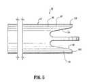
- FIG. 5is an enlarged side view of an alternate embodiment of the distal end of the catheter shown in FIG. 1 ;
- FIG. 6is an enlarged perspective view of another alternate embodiment of the catheter shown in FIG. 1 ;
- FIG. 7is an enlarged alternate perspective view of the catheter shown in FIG. 6 ;
- FIG. 8is an enlarged alternate perspective view of the catheter shown in FIG. 6 ;
- FIG. 9is an enlarged alternate perspective view of the catheter shown in FIG. 6 ;
- FIG. 10is a perspective view of another alternate embodiment of the catheter shown in FIG. 1 ;
- FIG. 11is a side view of the catheter shown in FIG. 10 ;
- FIG. 12is an alternate perspective view of the catheter shown in FIG. 10 ;
- FIG. 13is an alternate perspective view of the catheter shown in FIG. 10 ;
- FIG. 14is an alternate perspective view of the catheter shown in FIG. 10 ;
- FIG. 15is an alternate side view of the catheter shown in FIG. 10 ;
- FIG. 16is a perspective view of the catheter shown in FIG. 10 , illustrating fluid flow
- FIG. 17is a perspective view of the catheter shown in FIG. 10 , illustrating fluid flow.
- FIG. 18is a perspective side view of the catheter shown in FIG. 10 , illustrating fluid flow.
- the exemplary embodiments of the catheter and methods of use disclosedare discussed in terms of medical catheters for the administration of fluids (withdrawal, introduction, etc.) with the body of a subject and more particularly, in terms of a catheter including a catheter tip that prevents occlusion during use to facilitate unobstructed fluid flow.
- the catheteris advantageously configured to facilitate reversible fluid flow between lumens thereof. It is envisioned that the present disclosure may be employed with a range of catheters, such as, for example, hemodialysis, peritoneal, infusion, PICC, CVC, port, etc. and catheter applications including surgical, diagnostic and related treatments of diseases, body ailments, etc. of a subject.
- the principles relating to the catheter disclosedinclude employment with various catheter related procedures, such as, for example, hemodialysis, cardiac, abdominal, urinary, intestinal, etc., in chronic, acute, etc. applications. It is contemplated that the catheter can be used for administration of fluids such as, for example, medication, saline, bodily fluids such as, blood, urine, etc. The catheter may also be used to monitor subject condition.
- proximalwill refer to the portion of a structure that is closer to a practitioner, while the term “distal” will refer to the portion that is further from the practitioner.
- distalwill refer to the portion that is further from the practitioner.
- subjectrefers to a human patient or other animal.
- the term “practitioner”refers to a doctor, nurse or other care provider and may include support personnel.
- a catheter 10includes an elongated tubular body 12 that extends to a distal end 14 .
- Body 12has a first lumen 16 and a second lumen 18 , with a septum 20 disposed therebetween.
- Body 12includes a first wall 22 that defines first lumen 16 and a second wall 24 that defines second lumen 18 .
- a portion, such as, for example, septum extension 26 of septum 20extends distally beyond first lumen 16 and second lumen 18 .
- Septum 20is medially disposed, along a substantial portion of the longitudinal length of body 12 , between first lumen 16 and second lumen 18 .
- Septum 20may be variously disposed with body 12 , such as, for example, angularly offset relative to extended portions of the first and second walls, etc.
- First wall 22includes a first wall extension 28 that extends distally beyond first lumen 16 and is spaced apart from septum extension 26 .
- First wall extension 28defines a concave surface 30 that faces septum extension 26 .
- Second wall 24includes a second wall extension 32 that extends distally beyond second lumen 18 and is spaced apart from septum extension 26 .
- Second wall extension 32defines a concave surface 34 that faces septum extension 26 .
- Septum extension 26extends beyond first wall extension 28 and second wall extension 32 .
- Septum extension 26is medially disposed, as extending from body 12 , between first wall extension 28 and second wall extension 32 .
- Septum extension 26may be variously disposed for extension from body 12 .
- the disclosed configuration of catheter 10advantageously prevents occlusion of first lumen 16 and second lumen 18 , as will be discussed.
- One or a plurality of wall extensionsmay be employed with catheter 10 , according to the particular requirements of a catheter application.
- Body 12has a cylindrical outer surface 36 . It is contemplated that body 12 may be variously dimensioned and attachable to other medical devices. It is further contemplated that outer surface 36 may have various cross-sectional configurations, such as, for example, oval, rectangular, elliptical, polygonal, etc. Body 12 may also include lateral openings.
- First wall 22has a wall surface 38 that defines first lumen 16 in cooperation with a surface 40 of septum 20 .
- Second wall 24has a wall surface 42 that defines second lumen 18 in cooperation with a surface 44 of septum 20 .
- Lumens 16 , 18each may have a substantially D-shaped or semi-circular configuration. Lumens 16 , 18 are elongated with body 12 and surfaces 38 , 40 , 42 , 44 are configured to facilitate fluid flow within lumens 16 , 18 . It is contemplated that lumens 16 , 18 may be configured for arterial and/or venous flow. It is envisioned that lumens 16 , 18 may have various configurations, such as, for example, cylindrical, rectangular, elliptical, polygonal, etc. The first and second lumens may be configured for various forms of fluid flow in various directions and orientations, according to the requirements of a particular catheter application.
- Lumens 16 , 18may be uniformly dimensioned or include alternative dimensional cross sections within body 12 , such as, narrow and broad portions, converging surfaces, undulating surfaces, etc. according to the particular flow indications and/or flow rate requirements. It is contemplated lumen 16 and lumen 18 may extend alternative lengths. It is further contemplated that body 12 may include one or a plurality of lumens, such as, for example, a triple lumen configuration, etc.
- First lumen 16includes a first opening, such as, for example, an inlet opening 46 that is disposed adjacent to distal end 14 of body 12 .
- An outlet opening (not shown) of first lumen 16is disposed adjacent a proximal end 48 of body 12 .
- Inlet opening 46is configured for suction and may be inserted with a blood vessel of a subject (not shown) such that blood is withdrawn, by for example, arterial blood flow in a first direction, from the blood vessel for treatment by an artificial kidney device (not shown).
- Inlet opening 46may be variously dimensioned and configured, such as, for example, rectangular, elliptical, polygonal, etc. and may include adapters, clips, etc. to facilitate fluid flow and/or attachment to other structure. It is contemplated that inlet opening 46 may be configured for expulsion of fluid.
- Second lumen 18includes a second opening, such as, for example, an outlet opening 50 that is disposed adjacent to distal end 14 and in substantial longitudinal alignment, along body 12 , with inlet opening 46 .
- An inlet opening (not shown) of second lumen 18is disposed adjacent proximal end 48 .
- Outlet opening 50is configured for expulsion of fluid and introduces the treated blood from the artificial kidney device back into the blood vessel, by for example, venous blood flow in a second opposite direction.
- Outlet opening 50may be variously dimensioned and configured, such as, for example, rectangular, elliptical, polygonal, etc. and may include adapters, clips, etc. to facilitate fluid flow and/or attachment to other structure. It is contemplated that outlet opening 50 may be configured for withdrawal of fluid.
- catheter 10are fabricated from materials suitable for medical applications, such as, for example, polymerics or metals, such as stainless steel, depending on the particular catheter application and/or preference of a practitioner.
- materials suitable for medical applicationssuch as, for example, polymerics or metals, such as stainless steel, depending on the particular catheter application and/or preference of a practitioner.
- Semi-rigid and rigid polymericsare contemplated for fabrication, as well as resilient materials, such as molded medical grade polypropylene.
- resilient materialssuch as molded medical grade polypropylene.
- First wall extension 28extends distally, a distance a, beyond inlet opening 46 of first lumen 16 and outlet opening 50 of second lumen 18 . It is contemplated that distance a may extend various lengths according to the requirements of a particular catheter application, such as, for example, approximately 0.100–0.200 inches. Concave surface 30 faces a first planar surface 52 of septum extension 26 and is spaced apart therefrom a distance b. It is contemplated that distance b may extend various lengths. It is further contemplated that surface 52 may be non-planar, such as, for example, arcuate, undulating, textured, etc.
- Concave surface 30is bounded by a planar end surface 54 of first wall extension 28 and spans a radial distance c. End surface 54 extends about the perimeter of concave surface 30 such that first wall extension 28 has a scoop-like configuration that facilitates fluid flow through first lumen 16 . It is contemplated that first wall extension 28 may form alternate configurations, such as, for example, spherical, rectangular, etc. End surface 54 includes a radial portion 55 adjacent a distal end of first wall extension 28 . Radial portion 55 extends to the longitudinally oriented outer surface 36 of body 12 in an arcuate configuration. This configuration advantageously prevents a vessel wall (not shown) from becoming disposed within the inlet of first lumen 16 . In an alternate embodiment, as shown in FIG. 5 , a radial portion 155 extends to the longitudinally oriented outer surface 36 of body 12 in a perpendicular convergence.
- Planar end surface 54is disposed at an angular orientation a relative to first planar surface 52 . It is envisioned that end surface 54 may be disposed at various angular orientations a, such as, for example, 5–20 degrees.
- Concave surface 30 and first planar surface 52cooperate to define a first cavity 56 .
- First cavity 56is disposed distally beyond inlet opening 46 .
- First cavity 56is dimensioned and configured according to the bounds of one or all of inlet opening 46 , concave surface 30 , planar end surface 54 and septum extension 26 , according to the particular requirements of a catheter application.
- the extension of first cavity 56 distally beyond inlet opening 46prevents undesirable recirculation of fluid flow between first lumen 16 and second lumen 18 as facilitated by the barrier provided by septum extension 26 .
- Second wall extension 32extends distally, a distance d, beyond outlet opening 50 of second lumen 18 and inlet opening 46 of first lumen 16 . It is contemplated that distance d may extend various lengths according to the requirements of a particular catheter application, such as, for example, approximately 0.100–0.200 inches.
- Concave surface 34faces a second planar surface 58 of septum extension 26 , opposing first planar surface 52 , and is spaced apart therefrom a distance e.
- distance emay extend various lengths. It is further contemplated that surface 58 may be non-planar, such as, for example, arcuate, undulating, textured, etc. It is envisioned that surface 52 may be disposed at angular orientations relative to surface 58 .
- Concave surface 34is bounded by a planar end surface 60 of second wall extension 32 and spans a radial distance f. End surface 60 extends about the perimeter of concave surface 34 such that second wall extension 32 has a scoop-like configuration that facilitates fluid flow through second lumen 18 . It is envisioned that second wall extension 32 may form alternate configurations, such as, for example, spherical, rectangular, etc. End surface 60 includes a radial portion 61 adjacent a distal end of second wall extension 32 . Radial portion 61 extends to the longitudinally oriented outer surface 36 of body 12 in an arcuate configuration.
- a radial portion 161extends to the longitudinally oriented outer surface 36 in a perpendicular intersection.
- Planar end surface 60is disposed at an angular orientation ⁇ -relative to second planar surface 58 . It is envisioned that end surface 60 may be disposed at various orientations ⁇ , such as, for example, 5–20 degrees.
- Second cavity 62is disposed distally beyond outlet opening 50 .
- Second cavity 62is dimensioned and configured according to the bounds of one or all of outlet opening 50 , concave surface 34 , planar end surface 60 and septum extension 26 , according to the particular requirements of a catheter application.
- the extension of second cavity 62 distally beyond outlet opening 50prevents undesirable recirculation of fluid flow between second lumen 18 and first lumen 16 as facilitated by the barrier provided by septum extension 26 .
- First wall extension 28 and second wall extension 32are symmetrically disposed about septum extension 26 such that first cavity 56 and second cavity 62 are symmetrical.
- First cavity 56 and second cavity 62bound an equivalent space to facilitate inflow and outflow capability for each lumen.
- the space bounded by first cavity 56 and second cavity 62have an angular orientation as facilitated by respective planar end surfaces 54 , 60 , discussed above.
- the angular orientations of planar end surfaces 54 , 60 ( ⁇ , ⁇ )cause cavities 56 , 62 to direct fluid in the direction shown by the arrows in FIG. 4 .
- catheter 10advantageously facilitates reversible flow between first lumen 16 and second lumen 18 such that, for example, blood clots attaching to catheter 10 , including septum 20 , may be washed away by alternating blood flow directions.
- second lumen 18expels blood flow for introduction to the body vessel, blood flow is forced out of second lumen 18 .
- the blood flowis axially directed out of cavity 62 past second wall extension 32 . It is envisioned that such axially directed blood flow washes away any blood clots disposed adjacent cavity 62 .
- fluid flow exiting second lumen 18may wash other particles undesirably attached to catheter 10 . This configuration prevents undesirable recirculation of fluid flow between second lumen 18 and first lumen 16 .
- blood clots, etc. attached to catheter 10 , including septum 20may be washed away by alternating and/or reversing flow directions with consecutive dialysis. It is contemplated that the alternating and/or reversible flow may be provided by a source outside the body of catheter 10 such as, for example, a dialysis machine, etc. connected thereto.
- First lumen 16is provided with suction to withdraw fluids from the body vessel. Efficiency of fluid inflow through cavity 56 to first lumen 16 is improved due to the configuration of cavity 56 and consequent fluid direction. It is contemplated that blood clots, or other undesired particles, disposed adjacent cavity 56 of first lumen 16 may be washed away by reversing blood flow direction of lumens 16 , 18 with consecutive dialysis procedures. Upon reversal of blood flow direction, blood flow is expelled from cavity 56 and the axially directed blood flow washes away blood clots, similar to that described above. Second lumen 18 is provided with suction to withdraw fluids from the body vessel and into opening 50 .
- first wall extension 28 and second wall extension 32supports a vessel wall of a body vessel (not shown). This configuration spaces the vessel wall from inlet opening 46 and outlet opening 50 to prevent vessel wall occlusion of openings 46 , 50 during for example, suction through the lumens. It is further envisioned that first wall extension 28 and second wall extension 32 may have sufficient thickness and/or be fabricated from semi-rigid or rigid materials to prevent undesired deformation thereof.
- First wall 22includes a first wall extension 228 that extends distally beyond first lumen 16 and is spaced apart from septum extension 26 .
- First wall extension 228defines a concave surface 230 that faces septum extension 26 .
- Second wall 24includes a second wall extension 232 that extends distally beyond second lumen 18 and is spaced apart from septum extension 26 .
- Second wall extension 32defines a concave surface 234 that faces septum extension 26 .
- First wall extension 228includes a first step 212 and a second step 214 formed therewith.
- First step 212is formed with septum extension 26 .
- First step 212 and second step 214are circumferentially disposed about septum extension 26 . It is envisioned that first step 212 and/or second step 214 may have alternate configurations, such as, for example, planar, etc.
- First step 212extends distally, a distance aa, beyond inlet opening 46 of first lumen 16 and outlet opening 50 of second lumen 18 .
- Second step 214extends distally a distance bb, beyond inlet opening 46 and outlet opening 50 . It is contemplated that distance aa and bb may extend various lengths.
- Concave surface 230faces first planar surface 52 of septum extension 26 and is spaced apart therefrom. Concave surface 230 spans across approximately one-quarter of the circumference of body 12 or a substantially 90° arc as extended from septum extension 26 . It is envisioned that first step 212 and/or second step 214 , or other portions of concave surface 230 may be variously disposed about body 12 .
- Concave surface 230is bounded by a planar end surface 254 of first wall extension 228 . End surface 254 extends about the perimeter of concave surface 230 to facilitate fluid flow through first lumen 16 . Concave surface 230 and first planar surface 52 cooperate to define first cavity 56 , similar to that described above. First cavity 56 is further bounded by a proximal base 264 . Proximal base 264 defines a proximal inlet portion for first lumen 16 during withdrawal of fluids. It is contemplated that suction provided with first lumen 16 has a greater fluid flow rate adjacent proximal base 264 .
- Second wall extension 232includes a first step 216 and a second step 218 formed therewith.
- First step 216is formed with septum extension 26 .
- First step 216 and second step 218are circumferentially disposed about septum extension 26 . It is contemplated that first step 216 and/or second step 218 may have alternate configurations, such as, for example, planar, etc.
- First step 216extends distally, a distance dd, beyond outlet opening 50 and inlet opening 46 .
- Second step 218extends distally a distance ee, beyond inlet opening 46 and outlet opening 50 . It is contemplated that distances dd and ee may extend various lengths.
- Concave surface 234faces second planar surface 58 of septum extension 26 , opposing first planar surface 52 , and is spaced apart therefrom. Concave surface 234 spans across approximately one-quarter of the circumference of body 12 or a substantially 90° arc, as extended from septum extension 26 . It is envisioned that first step 216 and/or second step 218 , or other portions of concave surface 234 may be variously disposed about body 12 .
- Concave surface 234is bounded by a planar end surface 260 of second wall extension 232 . End surface 260 extends about the perimeter of concave surface 234 to facilitate fluid flow through second lumen 18 . Concave surface 234 and second planar surface 58 cooperate to define second cavity 62 , similar to that described above. Second cavity 62 is further bounded by a proximal base 266 . For example, if fluid flow is reversed with catheter 10 , proximal base 266 defines a proximal inlet portion for second lumen 18 during withdrawal of fluids. It is contemplated that suction provided with second lumen 18 has a greater fluid flow rate adjacent proximal base 266 .
- First wall extension 228 and second wall extension 232are symmetrically disposed about septum extension 26 such that first cavity 56 and second cavity 62 are symmetrical.
- First cavity 56 and second cavity 62bound an equivalent space to facilitate inflow and outflow capability for each lumen.
- catheter 10advantageously facilitates reversible flow between first lumen 16 and second lumen 18 such that, for example, blood clots attaching to catheter 10 may be washed away by alternating blood flow directions.
- second lumen 18expels blood flow for introduction to the body vessel, blood flow is forced out of second lumen 18 .
- the blood flowis axially directed out of cavity 62 past second wall extension 232 . It is envisioned that such axially directed blood flow washes away any blood clots disposed adjacent cavity 62 . It is further envisioned that fluid flow exiting second lumen 18 may wash other particles undesirably attached to catheter 10 .
- First lumen 16is provided with suction to withdraw fluids from the body vessel.
- the suctiondraws blood flow from various directions and orientations into inlet opening 46 .
- Suctionis greater adjacent proximal base 264 due to its closer proximity to a suction source (not shown). Fluid flow is greater adjacent to proximal base 264 and therefore, advantageously disposed proximal to the blood flow being expelled from cavity 62 of second lumen 18 . This configuration minimizes recirculation between lumens 16 , 18 .
- blood clots, or other undesired particles, disposed adjacent cavity 56 of first lumen 16may be washed away by reversing blood flow direction of lumens 16 , 18 .
- blood flowis expelled from cavity 56 and the axially directed blood flow washes away blood clots, similar to that described above.
- Second lumen 18is provided with suction to withdraw fluids from the body vessel and into opening 50 .
- Second wall extension 232is symmetrical with first wall extension 228 , and therefore, similar to proximal base 264 , suction is greater adjacent proximal base 266 . Fluid flow is greater adjacent to proximal base 266 and therefore, advantageously disposed proximal to the blood flow being expelled from cavity 56 . This configuration minimizes recirculation between lumens 16 , 18 .
- First wall 22includes a first wall extension 328 that extends distally beyond first lumen 16 and is spaced apart from septum extension 26 .
- First wall extension 328defines a concave surface 330 that faces septum extension 26 .
- Second wall 24includes a second wall extension 332 that extends distally beyond second lumen 18 and is spaced apart from septum extension 26 .
- Second wall extension 32defines a concave surface 334 that faces septum extension 26 .
- First wall extension 328includes a first step 312 and a second step 314 formed therewith in an arcuate transition.
- First step 312is formed with septum extension 26 in an arcuate transition.
- First step 312 and second step 314are circumferentially disposed about septum extension 26 . It is envisioned that first step 312 and/or second step 314 may have alternate configurations, such as, for example, planar, etc.
- First step 312extends distally, a distance aa, beyond inlet opening 46 of first lumen 16 and outlet opening 50 of second lumen 18 .
- Second step 314extends distally a distance bb, beyond inlet opening 46 and outlet opening 50 . It is contemplated that distance aa and bb may extend various lengths.
- Concave surface 330faces first planar surface 52 of septum extension 26 and is spaced apart therefrom. Concave surface 330 spans across approximately one-quarter of the circumference of body 12 or a substantially 90° arc as extended from septum extension 26 . It is envisioned that first step 312 and/or second step 314 , or other portions of concave surface 330 may be variously disposed about body 12 .
- Concave surface 330is bounded by a planar end surface 354 of first wall extension 328 . End surface 354 extends about the perimeter of concave surface 330 to facilitate fluid flow through first lumen 16 . Concave surface 330 and first planar surface 52 cooperate to define first cavity 56 , similar to that described above. First cavity 56 is further bounded by a proximal base 364 . Proximal base 364 has an arcuate configuration and defines a proximal inlet portion for first lumen 16 during withdrawal of fluids. It is contemplated that suction provided with first lumen 16 has a greater fluid flow rate adjacent proximal base 364 .
- Second wall extension 332includes a first step 316 and a second step 318 formed therewith in an arcuate transition.
- First step 316is formed with septum extension 26 .
- First step 316 and second step 318are circumferentially disposed about septum extension 26 . It is contemplated that first step 316 and/or second step 318 may have alternate configurations, such as, for example, planar, etc.
- First step 316extends distally, a distance dd, beyond outlet opening 50 and inlet opening 46 .
- Second step 318extends distally a distance ee, beyond inlet opening 46 and outlet opening 50 . It is contemplated that distances dd and ee may extend various lengths.
- Concave surface 334faces second planar surface 58 of septum extension 26 , opposing first planar surface 52 , and is spaced apart therefrom. Concave surface 334 spans across approximately one-quarter of the circumference of body 12 or a substantially 90° arc, as extended from septum extension 26 . It is envisioned that first step 316 and/or second step 318 , or other portions of concave surface 334 may be variously disposed about body 12 .
- Concave surface 334is bounded by a planar end surface 360 of second wall extension 332 . End surface 360 extends about the perimeter of concave surface 334 to facilitate fluid flow through second lumen 18 . Concave surface 334 and second planar surface 58 cooperate to define second cavity 62 , similar to that described above. Second cavity 62 is further bounded by a proximal base 366 .
- proximal base 366has an arcuate configuration and defines a proximal inlet portion for second lumen 18 during withdrawal of fluids. It is contemplated that suction provided with second lumen 18 has a greater fluid flow rate adjacent proximal base 366 .
- First wall extension 328 and second wall extension 332are symmetrically disposed about septum extension 26 such that first cavity 56 and second cavity 62 are symmetrical.
- First cavity 56 and second cavity 62bound an equivalent space to facilitate inflow and outflow capability for each lumen.
- catheter 10advantageously facilitates reversible flow between first lumen 16 and second lumen 18 by alternating blood flow directions.
- second lumen 18expels blood flow for introduction to the body vessel, blood flow is forced out of second lumen 18 .
- the blood flowis axially directed out of cavity 62 past second wall extension 332 . It is envisioned that such axially directed blood flow washes away any blood clots disposed adjacent cavity 62 .
- First lumen 16is provided with suction to withdraw fluids from the body vessel.
- the suctiondraws blood flow from various directions and orientations into inlet opening 46 .
- Suctionis greater adjacent proximal base 364 due to its closer proximity to a suction source (not shown). Fluid flow is greater adjacent to proximal base 364 and therefore, advantageously disposed proximal to the blood flow being expelled from cavity 62 of second lumen 18 . This configuration minimizes recirculation between lumens 16 , 18 .
- blood clots, or other undesired particles, disposed adjacent cavity 56 of first lumen 16may be washed away by reversing blood flow direction of lumens 16 , 18 .
- blood flowis expelled from cavity 56 and the axially directed blood flow washes away blood clots, similar to that described above.
- Second lumen 18is provided with suction to withdraw fluids from the body vessel and into opening 50 .
- Second wall extension 332is symmetrical with first wall extension 328 , and therefore, similar to proximal base 364 , suction is greater adjacent proximal base 366 . Fluid flow is greater adjacent to proximal base 366 and therefore, advantageously disposed proximal to the blood flow being expelled from cavity 56 . This configuration minimizes recirculation between lumens 16 , 18 .
Landscapes
- Health & Medical Sciences (AREA)
- Heart & Thoracic Surgery (AREA)
- Life Sciences & Earth Sciences (AREA)
- Hematology (AREA)
- Veterinary Medicine (AREA)
- Anesthesiology (AREA)
- Biomedical Technology (AREA)
- Engineering & Computer Science (AREA)
- Vascular Medicine (AREA)
- Animal Behavior & Ethology (AREA)
- General Health & Medical Sciences (AREA)
- Public Health (AREA)
- Pulmonology (AREA)
- Cardiology (AREA)
- Biophysics (AREA)
- Media Introduction/Drainage Providing Device (AREA)
- External Artificial Organs (AREA)
Abstract
Description
Claims (12)
Priority Applications (1)
| Application Number | Priority Date | Filing Date | Title |
|---|---|---|---|
| US10/482,881US7090654B2 (en) | 2003-03-28 | 2003-03-28 | Catheter with occlusion resistant tip |
Applications Claiming Priority (2)
| Application Number | Priority Date | Filing Date | Title |
|---|---|---|---|
| PCT/US2003/009687WO2004096334A1 (en) | 2003-03-28 | 2003-03-28 | Catheter with occlusion resistant tip |
| US10/482,881US7090654B2 (en) | 2003-03-28 | 2003-03-28 | Catheter with occlusion resistant tip |
Publications (2)
| Publication Number | Publication Date |
|---|---|
| US20050070842A1 US20050070842A1 (en) | 2005-03-31 |
| US7090654B2true US7090654B2 (en) | 2006-08-15 |
Family
ID=34375215
Family Applications (1)
| Application Number | Title | Priority Date | Filing Date |
|---|---|---|---|
| US10/482,881Expired - LifetimeUS7090654B2 (en) | 2003-03-28 | 2003-03-28 | Catheter with occlusion resistant tip |
Country Status (1)
| Country | Link |
|---|---|
| US (1) | US7090654B2 (en) |
Cited By (26)
| Publication number | Priority date | Publication date | Assignee | Title |
|---|---|---|---|---|
| US20050033264A1 (en)* | 2003-08-04 | 2005-02-10 | Peter Redinger | Catheter device |
| USD581529S1 (en) | 2007-10-12 | 2008-11-25 | C. R. Bard, Inc. | Catheter tip |
| US20090118661A1 (en)* | 2007-11-01 | 2009-05-07 | C. R. Bard, Inc. | Catheter assembly including triple lumen tip |
| US20090192435A1 (en)* | 2007-10-26 | 2009-07-30 | C. R. Bard, Inc. | Solid-body catheter including lateral distal openings |
| US8021321B2 (en) | 2002-02-07 | 2011-09-20 | C. R. Bard, Inc. | Split tip dialysis catheter |
| US8066660B2 (en) | 2007-10-26 | 2011-11-29 | C. R. Bard, Inc. | Split-tip catheter including lateral distal openings |
| US8152951B2 (en) | 2003-02-21 | 2012-04-10 | C. R. Bard, Inc. | Multi-lumen catheter with separate distal tips |
| US8206371B2 (en) | 2003-05-27 | 2012-06-26 | Bard Access Systems, Inc. | Methods and apparatus for inserting multi-lumen split-tip catheters into a blood vessel |
| US20130073770A1 (en)* | 2011-09-16 | 2013-03-21 | Schmitt Industries, Inc. | Portable controller for interfacing with process system components |
| US20130085456A1 (en)* | 2002-06-04 | 2013-04-04 | Irwin R. Berman | Applicator for Dispensing a Medicinal Substance and Methods Associated Therewith |
| US8500939B2 (en) | 2007-10-17 | 2013-08-06 | Bard Access Systems, Inc. | Manufacture of split tip catheters |
| US8636682B2 (en) | 2011-09-29 | 2014-01-28 | Covidien Lp | Catheter with articulable septum extension |
| US8992454B2 (en) | 2004-06-09 | 2015-03-31 | Bard Access Systems, Inc. | Splitable tip catheter with bioresorbable adhesive |
| US9044573B2 (en) | 2011-08-11 | 2015-06-02 | Phase One Medical, Llc | Method and apparatus for the dialysis of blood |
| US9126011B2 (en) | 2006-03-24 | 2015-09-08 | Merit Medical Systems, Inc. | Anti-clotting indwelling catheter |
| US9155862B2 (en) | 2012-09-28 | 2015-10-13 | Covidien Lp | Symmetrical tip acute catheter |
| US9155860B2 (en) | 2006-03-24 | 2015-10-13 | Merit Medical Systems, Inc. | Indwelling catheter with anti-clotting features |
| USD748252S1 (en) | 2013-02-08 | 2016-01-26 | C. R. Bard, Inc. | Multi-lumen catheter tip |
| US9579485B2 (en) | 2007-11-01 | 2017-02-28 | C. R. Bard, Inc. | Catheter assembly including a multi-lumen configuration |
| US9656043B2 (en) | 2011-03-08 | 2017-05-23 | Cook Medical Technologies Llc | Multi-split-tipped catheter |
| US10258768B2 (en) | 2014-07-14 | 2019-04-16 | C. R. Bard, Inc. | Apparatuses, systems, and methods for inserting catheters having enhanced stiffening and guiding features |
| USD905853S1 (en)* | 2018-02-27 | 2020-12-22 | Medical Components, Inc. | Catheter tip |
| US11141575B2 (en) | 2019-02-26 | 2021-10-12 | Ryan Maaskamp | Lipped medicinal applicator |
| US11351297B2 (en) | 2019-02-11 | 2022-06-07 | Ryan Maaskamp | Paddle shaped medicinal dispenser |
| USD984880S1 (en) | 2020-11-06 | 2023-05-02 | Medical Components, Inc. | Clamp with indicator |
| US12023460B1 (en) | 2022-08-25 | 2024-07-02 | Surgin, Inc. | Flow directing medicinal applicator |
Families Citing this family (2)
| Publication number | Priority date | Publication date | Assignee | Title |
|---|---|---|---|---|
| DE102005051211B4 (en)* | 2005-10-26 | 2008-11-06 | Bionic Medizintechnik Gmbh | Method for producing a multi-lumen catheter system |
| CN110339416A (en)* | 2019-07-08 | 2019-10-18 | 中南大学湘雅医院 | An irrigation device for thoracic surgery |
Citations (84)
| Publication number | Priority date | Publication date | Assignee | Title |
|---|---|---|---|---|
| US701075A (en) | 1902-02-19 | 1902-05-27 | Richard P Mccully | Catheter or like instrument. |
| US2541691A (en) | 1949-06-24 | 1951-02-13 | Clarence D Eicher | Embalmer's drainage instrument |
| FR2326941A1 (en) | 1975-10-06 | 1977-05-06 | Beelen Roger | HEMODIALYSIS NEEDLE |
| US4134402A (en) | 1976-02-11 | 1979-01-16 | Mahurkar Sakharam D | Double lumen hemodialysis catheter |
| USD254270S (en) | 1977-10-03 | 1980-02-19 | American Hospital Supply Corporation | Catheter deflector assembly for endoscopic instruments and the like |
| GB2028136A (en) | 1978-08-04 | 1980-03-05 | Wallace Ltd H G | Improvements in intravascular catheters |
| USD272651S (en) | 1981-11-02 | 1984-02-14 | Mahurkar Sakharam D | Double lumen catheter |
| US4443333A (en) | 1981-09-24 | 1984-04-17 | Mahurkar Sakharam D | Portable dialysis system and pump therefor |
| EP0107810A1 (en) | 1982-10-29 | 1984-05-09 | Miles Laboratories, Inc. | Long indwelling double bore catheter |
| US4568329A (en) | 1982-03-08 | 1986-02-04 | Mahurkar Sakharam D | Double lumen catheter |
| US4583968A (en) | 1983-10-03 | 1986-04-22 | Mahurkar Sakharam D | Smooth bore double lumen catheter |
| US4604379A (en) | 1984-06-18 | 1986-08-05 | Curators Of The University Of Missouri | Dialysis solutions containing cross-linked gelatin |
| USD289682S (en) | 1984-07-16 | 1987-05-05 | Dragan William B | Dental nozzle tip |
| US4675004A (en) | 1985-04-16 | 1987-06-23 | Quinton Instrument Company | Dual-lumen fistula needle |
| US4682978A (en) | 1984-05-24 | 1987-07-28 | Vas-Cath Of Canada Limited | Dual lumen cannula |
| US4687471A (en) | 1985-05-01 | 1987-08-18 | Curators Of The University Of Missouri | Peritoneal dialysis catheter |
| US4692141A (en) | 1982-03-08 | 1987-09-08 | Mahurkar Sakharam D | Double lumen catheter |
| USD292825S (en) | 1985-10-30 | 1987-11-17 | Dragan William B | Dental tip |
| US4770652A (en) | 1985-02-12 | 1988-09-13 | Mahurkar Sakharam D | Method and apparatus for using dual-lumen catheters for extracorporeal treatment |
| US4772269A (en) | 1985-05-01 | 1988-09-20 | Curators Of The University Of Missouri | Peritoneal dialysis catheter |
| USD298461S (en) | 1986-05-06 | 1988-11-08 | Vitalmetrics, Inc | Probe for surgical instrument |
| US4808155A (en) | 1986-02-27 | 1989-02-28 | Mahurkar Sakharam D | Simple double lumen catheter |
| US4842582A (en) | 1985-02-12 | 1989-06-27 | Mahurkar Sakharam D | Method and apparatus for using dual-lumen catheters for extracorporeal treatment |
| EP0341721A1 (en) | 1988-05-13 | 1989-11-15 | Dobrivoje Dr. Tomic | Dental treatment instrument with aspirating and irrigating device |
| US4883426A (en) | 1987-12-03 | 1989-11-28 | Ferrer Euler R | Dental implement for fluid aspiration and tissue retraction |
| US4895561A (en) | 1988-05-16 | 1990-01-23 | Mahurkar Sakharam D | Dual-lumen catheter-connecting system |
| US4904238A (en) | 1987-12-21 | 1990-02-27 | Alcon Laboratories, Inc. | Irrigation/aspiration handpiece |
| USD312872S (en) | 1987-11-09 | 1990-12-11 | Thomas Mahl | Dental suction head |
| US5009636A (en) | 1989-12-06 | 1991-04-23 | The Kendall Company | Dual-lumen catheter apparatus and method |
| US5015184A (en) | 1990-02-12 | 1991-05-14 | Lanny Perry | Evacuator tube tip guard |
| WO1992014500A1 (en) | 1991-02-26 | 1992-09-03 | Imt Innovative Medizintechnik Gmbh | Double-lumen catheter and process for producing an insertion profile on same |
| US5171227A (en) | 1991-04-16 | 1992-12-15 | The Curators Of The University Of Missouri | Separable peritoneal dialysis catheter |
| US5197951A (en) | 1983-12-14 | 1993-03-30 | Mahurkar Sakharam D | Simple double lumen catheter |
| US5209723A (en) | 1990-01-08 | 1993-05-11 | The Curators Of The University Of Missouri | Multiple lumen catheter for hemodialysis |
| US5221256A (en) | 1992-02-10 | 1993-06-22 | Mahurkar Sakharam D | Multiple-lumen catheter |
| US5221255A (en) | 1990-01-10 | 1993-06-22 | Mahurkar Sakharam D | Reinforced multiple lumen catheter |
| US5273527A (en) | 1992-05-12 | 1993-12-28 | Ovamed Corporation | Delivery catheter |
| US5281134A (en) | 1991-11-19 | 1994-01-25 | Schultz Allen J | Fiber optic illumination system for dental instruments |
| US5282788A (en) | 1992-02-26 | 1994-02-01 | Wilk Peter J | Method and device for obtaining continued transdermal access |
| US5290282A (en) | 1992-06-26 | 1994-03-01 | Christopher D. Casscells | Coagulating cannula |
| US5318518A (en) | 1991-08-14 | 1994-06-07 | Hp Medica Gesellschaft Mbh Fur Medizintechnische Systeme | Irrigating catheter |
| US5336165A (en) | 1991-08-21 | 1994-08-09 | Twardowski Zbylut J | Artificial kidney for frequent (daily) Hemodialysis |
| EP0623356A1 (en) | 1990-07-04 | 1994-11-09 | AVL Medical Instruments AG | Dual lumen needle for withdrawal of body fluids |
| US5374245A (en) | 1990-01-10 | 1994-12-20 | Mahurkar; Sakharam D. | Reinforced multiple-lumen catheter and apparatus and method for making the same |
| US5378230A (en) | 1993-11-01 | 1995-01-03 | Mahurkar; Sakharam D. | Triple-lumen critical care catheter |
| US5403291A (en) | 1993-08-02 | 1995-04-04 | Quinton Instrument Company | Catheter with elongated side holes |
| US5405320A (en) | 1990-01-08 | 1995-04-11 | The Curators Of The University Of Missouri | Multiple lumen catheter for hemodialysis |
| US5405341A (en) | 1993-06-03 | 1995-04-11 | Med-Pro Design, Inc. | Catheter with multiple lumens |
| WO1995010317A1 (en) | 1993-10-15 | 1995-04-20 | Kirkman Thomas R | Apparatus and method for retaining a catheter |
| US5419777A (en) | 1994-03-10 | 1995-05-30 | Bavaria Medizin Technologie Gmbh | Catheter for injecting a fluid or medicine |
| US5451216A (en) | 1993-06-15 | 1995-09-19 | Radius International Limited Partnership | Non-occluding catheter bolus |
| US5464398A (en) | 1990-11-27 | 1995-11-07 | Haindl; Hans | Catheter |
| US5486159A (en) | 1993-10-01 | 1996-01-23 | Mahurkar; Sakharam D. | Multiple-lumen catheter |
| US5536234A (en) | 1993-08-18 | 1996-07-16 | Vista Medical Technologies, Inc. | Optical surgical device with scraping tool |
| US5549541A (en) | 1993-02-11 | 1996-08-27 | Circon Corporation | Continuous flow cystoscope |
| US5554136A (en) | 1994-09-07 | 1996-09-10 | Luther Medical Products, Inc. | Dual lumen infusion/aspiration catheter |
| US5562640A (en) | 1991-10-18 | 1996-10-08 | United States Surgical Corporation | Endoscopic surgical instrument for aspiration and irrigation |
| US5569182A (en) | 1990-01-08 | 1996-10-29 | The Curators Of The University Of Missouri | Clot resistant multiple lumen catheter and method |
| US5571093A (en)* | 1994-09-21 | 1996-11-05 | Cruz; Cosme | Multiple-lumen catheter |
| US5607440A (en) | 1994-05-06 | 1997-03-04 | Endoscopic Concepts, Inc. | Trocar with lockable shield |
| US5707351A (en) | 1995-06-06 | 1998-01-13 | C.R. Bard, Inc. | Remote tubing assembly |
| US5725495A (en) | 1995-06-02 | 1998-03-10 | Surgical Design Corporation | Phacoemulsification handpiece, sleeve, and tip |
| US5776092A (en) | 1994-03-23 | 1998-07-07 | Erbe Elektromedizin Gmbh | Multifunctional surgical instrument |
| US5782797A (en) | 1996-06-06 | 1998-07-21 | Scimed Life Systems, Inc. | Therapeutic infusion device |
| US5785678A (en) | 1990-02-14 | 1998-07-28 | Cordis Corporation | Drainage catheter and method of using |
| US5788681A (en) | 1992-05-11 | 1998-08-04 | Medical Innovations Corporation | Multi-lumen endoscopic catheter |
| US5788680A (en) | 1996-07-09 | 1998-08-04 | Linder; Gerald Seymour | Dual-lumen suction catheter with multiple apertures in the vent lumen |
| US5801012A (en) | 1996-09-17 | 1998-09-01 | Northwestern University | Methods and compositions for generating angiostatin |
| US5830196A (en) | 1995-09-21 | 1998-11-03 | Tyco Group S.A.R.L. | Tapered and reinforced catheter |
| US5858009A (en) | 1997-08-14 | 1999-01-12 | Medtronic, Inc. | Multi-lumen cannula |
| US5902476A (en) | 1991-08-21 | 1999-05-11 | Twardowski; Zbylut J. | Artificial kidney for frequent (daily) hemodialysis |
| WO1999038550A1 (en) | 1998-01-30 | 1999-08-05 | Tyco Group S.A.E.L. | Multiple lumen catheter with an enlarged tip |
| US6086565A (en) | 1997-10-09 | 2000-07-11 | Asahi Kogaku Kogyo Kabushiki Kaisha | Syringe for endoscope |
| US6126631A (en) | 1994-04-04 | 2000-10-03 | Wake Forest University | Multi-lumen catheter system used in a blood treatment process |
| US6152910A (en) | 1996-09-13 | 2000-11-28 | Boston Scientific Corporation | Single operator exchange biliary catheter |
| US6190357B1 (en) | 1998-04-21 | 2001-02-20 | Cardiothoracic Systems, Inc. | Expandable cannula for performing cardiopulmonary bypass and method for using same |
| US6299444B1 (en) | 1999-08-04 | 2001-10-09 | East Coast Medical And Dental Devices, Inc. | Aspirator apparatus |
| US6409700B1 (en) | 1999-03-22 | 2002-06-25 | Cfd Research Corporation | Double lumen catheter |
| US6423050B1 (en) | 2000-06-16 | 2002-07-23 | Zbylut J. Twardowski | Method and apparatus for locking of central-vein catheters |
| US6428502B1 (en) | 1999-06-25 | 2002-08-06 | Alcon Manufacturing, Ltd. | Punctal cannula |
| US6461321B1 (en)* | 2000-08-30 | 2002-10-08 | Radius International Limited Partnership | Hemodialysis catheter |
| US6592565B2 (en) | 2001-04-26 | 2003-07-15 | Zbylut J. Twardowski | Patient-tailored, central-vein catheters |
| US6702776B2 (en)* | 1999-11-24 | 2004-03-09 | Radius International Limited Partnership | Blood vessel catheter |
| US6786884B1 (en)* | 1999-10-29 | 2004-09-07 | Bard Access Systems, Inc. | Bolus tip design for a multi-lumen catheter |
Family Cites Families (24)
| Publication number | Priority date | Publication date | Assignee | Title |
|---|---|---|---|---|
| US850603A (en)* | 1905-05-16 | 1907-04-16 | George Reiter | Slipper for soaking the feet. |
| US1257086A (en)* | 1917-04-03 | 1918-02-19 | Hart W Marcellus | Hot-water boot. |
| US1748607A (en)* | 1928-06-26 | 1930-02-25 | Edwin S Jarrett | Emergency protective covering |
| US1980486A (en)* | 1931-11-14 | 1934-11-13 | Le Roy M King | Surgical foot covering |
| US2248303A (en)* | 1938-02-14 | 1941-07-08 | Morgenroth Frank | Art of treating foot ailments |
| US2154662A (en)* | 1938-06-06 | 1939-04-18 | Bucks David Hiram | Toe shield |
| US2400023A (en)* | 1944-09-01 | 1946-05-07 | Orville V Potter | Foot massaging device |
| US2658510A (en)* | 1951-04-26 | 1953-11-10 | Joyce J Hilton | Protective covering for feet or hands |
| US2649588A (en)* | 1952-02-01 | 1953-08-25 | Alex Lee Wallau Inc | Footcap |
| US2771691A (en)* | 1954-09-22 | 1956-11-27 | J W Landenberger & Co | Cushioned foot protector |
| US2896339A (en)* | 1955-02-28 | 1959-07-28 | Rabinowitz Albert | Foot protector |
| US3148463A (en)* | 1962-10-18 | 1964-09-15 | Douglas G Tibbitts Jr | Disposable tissue sock |
| US3148378A (en)* | 1962-12-31 | 1964-09-15 | Douglas G Tibbitts Jr | Disposable tissue sock and one-piece tissue paper blank for same |
| US3324580A (en)* | 1965-07-07 | 1967-06-13 | Thomas R Baxter | Foot covering |
| US3380178A (en)* | 1966-04-08 | 1968-04-30 | Haig Sarah | Heel garment and combination footwear and heel garment |
| US4296499A (en)* | 1979-05-29 | 1981-10-27 | Theodore P. Patterson | Blister preventing foot cover |
| FR2575044B1 (en)* | 1984-12-21 | 1987-10-09 | Dispovet | PROTECTIVE SHOE ADAPTABLE TO DIFFERENT SIZES |
| US4649910A (en)* | 1985-05-31 | 1987-03-17 | Meridian Industries Inc. | Orthopedic stocking |
| US4811499A (en)* | 1988-04-15 | 1989-03-14 | Jensen Harold A | Hygenic plastic footwear insert |
| US5319807A (en)* | 1993-05-25 | 1994-06-14 | Brier Daniel L | Moisture-management sock and shoe for creating a moisture managing environment for the feet |
| TW249196B (en)* | 1993-07-23 | 1995-06-11 | James L Throneburg | |
| BR9602748A (en)* | 1995-06-13 | 1998-04-22 | Faytex Corp | Footwear frame |
| US6393734B1 (en)* | 2001-02-26 | 2002-05-28 | Chan-Chou Ou | Adjustable and disposable foot care article |
| US6742289B2 (en)* | 2002-07-01 | 2004-06-01 | Medical Device Group, Inc. | Stress reduction kit and method of using same |
- 2003
- 2003-03-28USUS10/482,881patent/US7090654B2/ennot_activeExpired - Lifetime
Patent Citations (96)
| Publication number | Priority date | Publication date | Assignee | Title |
|---|---|---|---|---|
| US701075A (en) | 1902-02-19 | 1902-05-27 | Richard P Mccully | Catheter or like instrument. |
| US2541691A (en) | 1949-06-24 | 1951-02-13 | Clarence D Eicher | Embalmer's drainage instrument |
| FR2326941A1 (en) | 1975-10-06 | 1977-05-06 | Beelen Roger | HEMODIALYSIS NEEDLE |
| US4134402B1 (en) | 1976-02-11 | 1989-07-25 | ||
| US4134402A (en) | 1976-02-11 | 1979-01-16 | Mahurkar Sakharam D | Double lumen hemodialysis catheter |
| USD254270S (en) | 1977-10-03 | 1980-02-19 | American Hospital Supply Corporation | Catheter deflector assembly for endoscopic instruments and the like |
| GB2028136A (en) | 1978-08-04 | 1980-03-05 | Wallace Ltd H G | Improvements in intravascular catheters |
| US4443333A (en) | 1981-09-24 | 1984-04-17 | Mahurkar Sakharam D | Portable dialysis system and pump therefor |
| USD272651S (en) | 1981-11-02 | 1984-02-14 | Mahurkar Sakharam D | Double lumen catheter |
| US4568329A (en) | 1982-03-08 | 1986-02-04 | Mahurkar Sakharam D | Double lumen catheter |
| US4692141A (en) | 1982-03-08 | 1987-09-08 | Mahurkar Sakharam D | Double lumen catheter |
| EP0107810A1 (en) | 1982-10-29 | 1984-05-09 | Miles Laboratories, Inc. | Long indwelling double bore catheter |
| US4601697A (en) | 1982-10-29 | 1986-07-22 | Miles Laboratories, Inc. | Long indwelling double bore catheter |
| US4583968A (en) | 1983-10-03 | 1986-04-22 | Mahurkar Sakharam D | Smooth bore double lumen catheter |
| US5197951A (en) | 1983-12-14 | 1993-03-30 | Mahurkar Sakharam D | Simple double lumen catheter |
| US4682978A (en) | 1984-05-24 | 1987-07-28 | Vas-Cath Of Canada Limited | Dual lumen cannula |
| US4604379A (en) | 1984-06-18 | 1986-08-05 | Curators Of The University Of Missouri | Dialysis solutions containing cross-linked gelatin |
| USD289682S (en) | 1984-07-16 | 1987-05-05 | Dragan William B | Dental nozzle tip |
| US4842582A (en) | 1985-02-12 | 1989-06-27 | Mahurkar Sakharam D | Method and apparatus for using dual-lumen catheters for extracorporeal treatment |
| US4770652A (en) | 1985-02-12 | 1988-09-13 | Mahurkar Sakharam D | Method and apparatus for using dual-lumen catheters for extracorporeal treatment |
| US4675004A (en) | 1985-04-16 | 1987-06-23 | Quinton Instrument Company | Dual-lumen fistula needle |
| US4772269A (en) | 1985-05-01 | 1988-09-20 | Curators Of The University Of Missouri | Peritoneal dialysis catheter |
| US4687471A (en) | 1985-05-01 | 1987-08-18 | Curators Of The University Of Missouri | Peritoneal dialysis catheter |
| US4772269B1 (en) | 1985-05-01 | 1992-05-19 | Univ Missouri | |
| USD292825S (en) | 1985-10-30 | 1987-11-17 | Dragan William B | Dental tip |
| US4808155A (en) | 1986-02-27 | 1989-02-28 | Mahurkar Sakharam D | Simple double lumen catheter |
| USD298461S (en) | 1986-05-06 | 1988-11-08 | Vitalmetrics, Inc | Probe for surgical instrument |
| USD312872S (en) | 1987-11-09 | 1990-12-11 | Thomas Mahl | Dental suction head |
| US4883426A (en) | 1987-12-03 | 1989-11-28 | Ferrer Euler R | Dental implement for fluid aspiration and tissue retraction |
| US4904238A (en) | 1987-12-21 | 1990-02-27 | Alcon Laboratories, Inc. | Irrigation/aspiration handpiece |
| EP0341721A1 (en) | 1988-05-13 | 1989-11-15 | Dobrivoje Dr. Tomic | Dental treatment instrument with aspirating and irrigating device |
| US4895561A (en) | 1988-05-16 | 1990-01-23 | Mahurkar Sakharam D | Dual-lumen catheter-connecting system |
| US5009636A (en) | 1989-12-06 | 1991-04-23 | The Kendall Company | Dual-lumen catheter apparatus and method |
| US5569182A (en) | 1990-01-08 | 1996-10-29 | The Curators Of The University Of Missouri | Clot resistant multiple lumen catheter and method |
| US5509897A (en) | 1990-01-08 | 1996-04-23 | The Curators Of The University Of Missouri | Multiple lumen catheter for hemodialysis |
| US5405320A (en) | 1990-01-08 | 1995-04-11 | The Curators Of The University Of Missouri | Multiple lumen catheter for hemodialysis |
| US5209723A (en) | 1990-01-08 | 1993-05-11 | The Curators Of The University Of Missouri | Multiple lumen catheter for hemodialysis |
| US5685867A (en) | 1990-01-08 | 1997-11-11 | The Curators Of The University Of Missouri | Clot resistant multiple lumen catheter |
| US5221255A (en) | 1990-01-10 | 1993-06-22 | Mahurkar Sakharam D | Reinforced multiple lumen catheter |
| US5374245A (en) | 1990-01-10 | 1994-12-20 | Mahurkar; Sakharam D. | Reinforced multiple-lumen catheter and apparatus and method for making the same |
| US5015184A (en) | 1990-02-12 | 1991-05-14 | Lanny Perry | Evacuator tube tip guard |
| US5785678A (en) | 1990-02-14 | 1998-07-28 | Cordis Corporation | Drainage catheter and method of using |
| EP0623356A1 (en) | 1990-07-04 | 1994-11-09 | AVL Medical Instruments AG | Dual lumen needle for withdrawal of body fluids |
| US5464398A (en) | 1990-11-27 | 1995-11-07 | Haindl; Hans | Catheter |
| WO1992014500A1 (en) | 1991-02-26 | 1992-09-03 | Imt Innovative Medizintechnik Gmbh | Double-lumen catheter and process for producing an insertion profile on same |
| US5171227A (en) | 1991-04-16 | 1992-12-15 | The Curators Of The University Of Missouri | Separable peritoneal dialysis catheter |
| US5318518A (en) | 1991-08-14 | 1994-06-07 | Hp Medica Gesellschaft Mbh Fur Medizintechnische Systeme | Irrigating catheter |
| US5902476A (en) | 1991-08-21 | 1999-05-11 | Twardowski; Zbylut J. | Artificial kidney for frequent (daily) hemodialysis |
| US5336165A (en) | 1991-08-21 | 1994-08-09 | Twardowski Zbylut J | Artificial kidney for frequent (daily) Hemodialysis |
| US6132616A (en) | 1991-08-21 | 2000-10-17 | Twardowski; Zbylut J. | Method for flushing and filling of an extracorporeal blood circulation system of a dialysis machine |
| US6146536A (en) | 1991-08-21 | 2000-11-14 | Twardowski; Zbylut J. | Method of preparing a batch of dialysis solution |
| US5484397A (en) | 1991-08-21 | 1996-01-16 | Twardowski; Zbylut J. | Artificial kidney for frequent (daily) hemodialysis |
| US5562640A (en) | 1991-10-18 | 1996-10-08 | United States Surgical Corporation | Endoscopic surgical instrument for aspiration and irrigation |
| US5281134A (en) | 1991-11-19 | 1994-01-25 | Schultz Allen J | Fiber optic illumination system for dental instruments |
| EP0555780A2 (en) | 1992-02-10 | 1993-08-18 | Sakharam Dhundiraj Mahurkar | Multiple-lumen catheter |
| US5221256A (en) | 1992-02-10 | 1993-06-22 | Mahurkar Sakharam D | Multiple-lumen catheter |
| US5282788A (en) | 1992-02-26 | 1994-02-01 | Wilk Peter J | Method and device for obtaining continued transdermal access |
| US5788681A (en) | 1992-05-11 | 1998-08-04 | Medical Innovations Corporation | Multi-lumen endoscopic catheter |
| US5273527A (en) | 1992-05-12 | 1993-12-28 | Ovamed Corporation | Delivery catheter |
| US5290282A (en) | 1992-06-26 | 1994-03-01 | Christopher D. Casscells | Coagulating cannula |
| US5549541A (en) | 1993-02-11 | 1996-08-27 | Circon Corporation | Continuous flow cystoscope |
| US5405341A (en) | 1993-06-03 | 1995-04-11 | Med-Pro Design, Inc. | Catheter with multiple lumens |
| US5451216A (en) | 1993-06-15 | 1995-09-19 | Radius International Limited Partnership | Non-occluding catheter bolus |
| US5403291A (en) | 1993-08-02 | 1995-04-04 | Quinton Instrument Company | Catheter with elongated side holes |
| US5536234A (en) | 1993-08-18 | 1996-07-16 | Vista Medical Technologies, Inc. | Optical surgical device with scraping tool |
| US5486159A (en) | 1993-10-01 | 1996-01-23 | Mahurkar; Sakharam D. | Multiple-lumen catheter |
| WO1995010317A1 (en) | 1993-10-15 | 1995-04-20 | Kirkman Thomas R | Apparatus and method for retaining a catheter |
| US5378230A (en) | 1993-11-01 | 1995-01-03 | Mahurkar; Sakharam D. | Triple-lumen critical care catheter |
| US5419777A (en) | 1994-03-10 | 1995-05-30 | Bavaria Medizin Technologie Gmbh | Catheter for injecting a fluid or medicine |
| US5776092A (en) | 1994-03-23 | 1998-07-07 | Erbe Elektromedizin Gmbh | Multifunctional surgical instrument |
| US6126631A (en) | 1994-04-04 | 2000-10-03 | Wake Forest University | Multi-lumen catheter system used in a blood treatment process |
| US6063099A (en) | 1994-05-06 | 2000-05-16 | Endoscopic Concepts, Inc. | Dilating trocar shield with blade tip |
| US5607440A (en) | 1994-05-06 | 1997-03-04 | Endoscopic Concepts, Inc. | Trocar with lockable shield |
| US5554136A (en) | 1994-09-07 | 1996-09-10 | Luther Medical Products, Inc. | Dual lumen infusion/aspiration catheter |
| US5571093A (en)* | 1994-09-21 | 1996-11-05 | Cruz; Cosme | Multiple-lumen catheter |
| US5961486A (en) | 1995-02-09 | 1999-10-05 | Twardowski; Zbylut J. | Clot resistant multiple lumen catheter |
| US5725495A (en) | 1995-06-02 | 1998-03-10 | Surgical Design Corporation | Phacoemulsification handpiece, sleeve, and tip |
| US5707351A (en) | 1995-06-06 | 1998-01-13 | C.R. Bard, Inc. | Remote tubing assembly |
| US5830196A (en) | 1995-09-21 | 1998-11-03 | Tyco Group S.A.R.L. | Tapered and reinforced catheter |
| US5782797A (en) | 1996-06-06 | 1998-07-21 | Scimed Life Systems, Inc. | Therapeutic infusion device |
| US5788680A (en) | 1996-07-09 | 1998-08-04 | Linder; Gerald Seymour | Dual-lumen suction catheter with multiple apertures in the vent lumen |
| US6152910A (en) | 1996-09-13 | 2000-11-28 | Boston Scientific Corporation | Single operator exchange biliary catheter |
| US5801012A (en) | 1996-09-17 | 1998-09-01 | Northwestern University | Methods and compositions for generating angiostatin |
| US6576609B1 (en) | 1996-09-17 | 2003-06-10 | Northwestern University | Methods and compositions for generating angiostatin |
| US5858009A (en) | 1997-08-14 | 1999-01-12 | Medtronic, Inc. | Multi-lumen cannula |
| US6086565A (en) | 1997-10-09 | 2000-07-11 | Asahi Kogaku Kogyo Kabushiki Kaisha | Syringe for endoscope |
| WO1999038550A1 (en) | 1998-01-30 | 1999-08-05 | Tyco Group S.A.E.L. | Multiple lumen catheter with an enlarged tip |
| US6190357B1 (en) | 1998-04-21 | 2001-02-20 | Cardiothoracic Systems, Inc. | Expandable cannula for performing cardiopulmonary bypass and method for using same |
| US6409700B1 (en) | 1999-03-22 | 2002-06-25 | Cfd Research Corporation | Double lumen catheter |
| US6428502B1 (en) | 1999-06-25 | 2002-08-06 | Alcon Manufacturing, Ltd. | Punctal cannula |
| US6299444B1 (en) | 1999-08-04 | 2001-10-09 | East Coast Medical And Dental Devices, Inc. | Aspirator apparatus |
| US6786884B1 (en)* | 1999-10-29 | 2004-09-07 | Bard Access Systems, Inc. | Bolus tip design for a multi-lumen catheter |
| US6702776B2 (en)* | 1999-11-24 | 2004-03-09 | Radius International Limited Partnership | Blood vessel catheter |
| US6423050B1 (en) | 2000-06-16 | 2002-07-23 | Zbylut J. Twardowski | Method and apparatus for locking of central-vein catheters |
| US6461321B1 (en)* | 2000-08-30 | 2002-10-08 | Radius International Limited Partnership | Hemodialysis catheter |
| US6592565B2 (en) | 2001-04-26 | 2003-07-15 | Zbylut J. Twardowski | Patient-tailored, central-vein catheters |
Cited By (64)
| Publication number | Priority date | Publication date | Assignee | Title |
|---|---|---|---|---|
| US8021321B2 (en) | 2002-02-07 | 2011-09-20 | C. R. Bard, Inc. | Split tip dialysis catheter |
| US9132262B2 (en)* | 2002-06-04 | 2015-09-15 | Irwin R. Berman | Applicator for dispensing a medicinal substance |
| US20130085456A1 (en)* | 2002-06-04 | 2013-04-04 | Irwin R. Berman | Applicator for Dispensing a Medicinal Substance and Methods Associated Therewith |
| US8152951B2 (en) | 2003-02-21 | 2012-04-10 | C. R. Bard, Inc. | Multi-lumen catheter with separate distal tips |
| US9387304B2 (en) | 2003-02-21 | 2016-07-12 | C.R. Bard, Inc. | Multi-lumen catheter with separate distal tips |
| US8808227B2 (en) | 2003-02-21 | 2014-08-19 | C. R. Bard, Inc. | Multi-lumen catheter with separate distal tips |
| US9572956B2 (en) | 2003-05-27 | 2017-02-21 | Bard Access Systems, Inc. | Methods and apparatus for inserting multi-lumen split-tip catheters into a blood vessel |
| US8206371B2 (en) | 2003-05-27 | 2012-06-26 | Bard Access Systems, Inc. | Methods and apparatus for inserting multi-lumen split-tip catheters into a blood vessel |
| US10105514B2 (en) | 2003-05-27 | 2018-10-23 | Bard Access Systems, Inc. | Methods and apparatus for inserting multi-lumen split-tip catheters into a blood vessel |
| US10806895B2 (en) | 2003-05-27 | 2020-10-20 | Bard Access Systems, Inc. | Methods and apparatus for inserting multi-lumen split-tip catheters into a blood vessel |
| US8597275B2 (en) | 2003-05-27 | 2013-12-03 | Bard Access Systems, Inc. | Methods and apparatus for inserting multi-lumen split-tip catheters into a blood vessel |
| US7322953B2 (en)* | 2003-08-04 | 2008-01-29 | Covidien Ag | Catheter device |
| US20050033264A1 (en)* | 2003-08-04 | 2005-02-10 | Peter Redinger | Catheter device |
| US9669149B2 (en) | 2004-06-09 | 2017-06-06 | Bard Access Systems, Inc. | Splitable tip catheter with bioresorbable adhesive |
| US9782535B2 (en) | 2004-06-09 | 2017-10-10 | Bard Access Systems, Inc. | Splitable tip catheter with bioresorbable adhesive |
| US8992454B2 (en) | 2004-06-09 | 2015-03-31 | Bard Access Systems, Inc. | Splitable tip catheter with bioresorbable adhesive |
| US9155860B2 (en) | 2006-03-24 | 2015-10-13 | Merit Medical Systems, Inc. | Indwelling catheter with anti-clotting features |
| US9126011B2 (en) | 2006-03-24 | 2015-09-08 | Merit Medical Systems, Inc. | Anti-clotting indwelling catheter |
| USD581529S1 (en) | 2007-10-12 | 2008-11-25 | C. R. Bard, Inc. | Catheter tip |
| US8500939B2 (en) | 2007-10-17 | 2013-08-06 | Bard Access Systems, Inc. | Manufacture of split tip catheters |
| US20160121040A1 (en)* | 2007-10-26 | 2016-05-05 | C. R. Bard, Inc. | Split-Tip Catheter Including Lateral Distal Openings |
| US10258732B2 (en)* | 2007-10-26 | 2019-04-16 | C. R. Bard, Inc. | Split-tip catheter including lateral distal openings |
| US8696614B2 (en) | 2007-10-26 | 2014-04-15 | C. R. Bard, Inc. | Split-tip catheter including lateral distal openings |
| US11338075B2 (en) | 2007-10-26 | 2022-05-24 | C. R. Bard, Inc. | Split-tip catheter including lateral distal openings |
| US11260161B2 (en) | 2007-10-26 | 2022-03-01 | C. R. Bard, Inc. | Solid-body catheter including lateral distal openings |
| US12076475B2 (en) | 2007-10-26 | 2024-09-03 | C. R. Bard, Inc. | Split-tip catheter including lateral distal openings |
| US10207043B2 (en) | 2007-10-26 | 2019-02-19 | C. R. Bard, Inc. | Solid-body catheter including lateral distal openings |
| US20090192435A1 (en)* | 2007-10-26 | 2009-07-30 | C. R. Bard, Inc. | Solid-body catheter including lateral distal openings |
| US20140025042A1 (en)* | 2007-10-26 | 2014-01-23 | C. R. Bard, Inc. | Solid-Body Catheter Including Lateral Distal Openings |
| US9174019B2 (en)* | 2007-10-26 | 2015-11-03 | C. R. Bard, Inc. | Solid-body catheter including lateral distal openings |
| US9233200B2 (en) | 2007-10-26 | 2016-01-12 | C.R. Bard, Inc. | Split-tip catheter including lateral distal openings |
| US8066660B2 (en) | 2007-10-26 | 2011-11-29 | C. R. Bard, Inc. | Split-tip catheter including lateral distal openings |
| US8540661B2 (en) | 2007-10-26 | 2013-09-24 | C. R. Bard, Inc. | Solid-body catheter including lateral distal openings |
| US8292841B2 (en)* | 2007-10-26 | 2012-10-23 | C. R. Bard, Inc. | Solid-body catheter including lateral distal openings |
| US20090118661A1 (en)* | 2007-11-01 | 2009-05-07 | C. R. Bard, Inc. | Catheter assembly including triple lumen tip |
| US11918758B2 (en) | 2007-11-01 | 2024-03-05 | C. R. Bard, Inc. | Catheter assembly including a multi-lumen configuration |
| US9579485B2 (en) | 2007-11-01 | 2017-02-28 | C. R. Bard, Inc. | Catheter assembly including a multi-lumen configuration |
| US9610422B2 (en) | 2007-11-01 | 2017-04-04 | C. R. Bard, Inc. | Catheter assembly |
| US10518064B2 (en) | 2007-11-01 | 2019-12-31 | C. R. Bard, Inc. | Catheter assembly including a multi-lumen configuration |
| US8092415B2 (en) | 2007-11-01 | 2012-01-10 | C. R. Bard, Inc. | Catheter assembly including triple lumen tip |
| US8894601B2 (en) | 2007-11-01 | 2014-11-25 | C. R. Bard, Inc. | Catheter assembly including triple lumen tip |
| US9656043B2 (en) | 2011-03-08 | 2017-05-23 | Cook Medical Technologies Llc | Multi-split-tipped catheter |
| US10765794B2 (en) | 2011-08-11 | 2020-09-08 | Medical Components, Inc. | Method and apparatus for the dialysis of blood |
| US10004842B2 (en) | 2011-08-11 | 2018-06-26 | Medical Components, Inc. | Method and apparatus for the dialysis of blood |
| US10765795B2 (en) | 2011-08-11 | 2020-09-08 | Medical Components, Inc. | Method and apparatus for the dialysis of blood |
| US11696981B2 (en) | 2011-08-11 | 2023-07-11 | Medical Components, Inc. | Method and apparatus for the dialysis of blood |
| US9044573B2 (en) | 2011-08-11 | 2015-06-02 | Phase One Medical, Llc | Method and apparatus for the dialysis of blood |
| US20130073770A1 (en)* | 2011-09-16 | 2013-03-21 | Schmitt Industries, Inc. | Portable controller for interfacing with process system components |
| US8639869B2 (en)* | 2011-09-16 | 2014-01-28 | Schmitt Industries, Inc. | Portable controller for interfacing with process system components |
| US8636682B2 (en) | 2011-09-29 | 2014-01-28 | Covidien Lp | Catheter with articulable septum extension |
| US9056183B2 (en) | 2011-09-29 | 2015-06-16 | Covidien Lp | Catheter with articulable septum extension |
| US11413426B2 (en) | 2012-09-28 | 2022-08-16 | Covidien Lp | Symmetrical tip acute catheter |
| US9155862B2 (en) | 2012-09-28 | 2015-10-13 | Covidien Lp | Symmetrical tip acute catheter |
| US9526861B2 (en) | 2012-09-28 | 2016-12-27 | Covidien Lp | Symmetrical tip acute catheter |
| US11554247B2 (en) | 2012-09-28 | 2023-01-17 | Covidien Lp | Symmetrical tip acute catheter |
| USD748252S1 (en) | 2013-02-08 | 2016-01-26 | C. R. Bard, Inc. | Multi-lumen catheter tip |
| US10857330B2 (en) | 2014-07-14 | 2020-12-08 | C. R. Bard, Inc. | Apparatuses, systems, and methods for inserting catheters having enhanced stiffening and guiding features |
| US10258768B2 (en) | 2014-07-14 | 2019-04-16 | C. R. Bard, Inc. | Apparatuses, systems, and methods for inserting catheters having enhanced stiffening and guiding features |
| USD905853S1 (en)* | 2018-02-27 | 2020-12-22 | Medical Components, Inc. | Catheter tip |
| US11351297B2 (en) | 2019-02-11 | 2022-06-07 | Ryan Maaskamp | Paddle shaped medicinal dispenser |
| US11141575B2 (en) | 2019-02-26 | 2021-10-12 | Ryan Maaskamp | Lipped medicinal applicator |
| USD984880S1 (en) | 2020-11-06 | 2023-05-02 | Medical Components, Inc. | Clamp with indicator |
| US12023460B1 (en) | 2022-08-25 | 2024-07-02 | Surgin, Inc. | Flow directing medicinal applicator |
| US12144948B2 (en) | 2022-08-25 | 2024-11-19 | Medicele Llc | Flow directing medicinal applicator |
Also Published As
| Publication number | Publication date |
|---|---|
| US20050070842A1 (en) | 2005-03-31 |
Similar Documents
| Publication | Publication Date | Title |
|---|---|---|
| US7141035B2 (en) | Catheter with occlusion resistant tip | |
| US7776005B2 (en) | Triple lumen catheter with occlusion resistant tip | |
| US7090654B2 (en) | Catheter with occlusion resistant tip | |
| CA2520572C (en) | Catheter with occlusion resistant tip | |
| JP2008503274A5 (en) | ||
| JP2007524452A5 (en) | ||
| ZA200508692B (en) | Catheter with occlusion resistant tip | |
| HK1079468B (en) | Catheter with occlusion resistant tip | |
| NZ543012A (en) | Catheter with occlusion resistant tip | |
| HK1083320B (en) | Catheter with occlusion resistant tip | |
| HK1095103B (en) | Triple lumen catheter with occlusion resistant tip |
Legal Events
| Date | Code | Title | Description |
|---|---|---|---|
| AS | Assignment | Owner name:SHERWOOD SERVICES AG, SWITZERLAND Free format text:ASSIGNMENT OF ASSIGNORS INTEREST;ASSIGNORS:LOTITO, MARK;TRUPIANAO, ANTHONY;SANCOUCY, MICHAEL;AND OTHERS;REEL/FRAME:014380/0797;SIGNING DATES FROM 20030423 TO 20030424 | |
| STCF | Information on status: patent grant | Free format text:PATENTED CASE | |
| AS | Assignment | Owner name:COVIDIEN AG, SWITZERLAND Free format text:CHANGE OF NAME;ASSIGNOR:SHERWOOD SERVICES AG;REEL/FRAME:021371/0142 Effective date:20070309 | |
| FPAY | Fee payment | Year of fee payment:4 | |
| AS | Assignment | Owner name:TYCO HEALTHCARE GROUP AG,SWITZERLAND Free format text:MERGER;ASSIGNOR:COVIDIEN AG;REEL/FRAME:024185/0164 Effective date:20081215 Owner name:COVIDIEN AG,SWITZERLAND Free format text:CHANGE OF NAME;ASSIGNOR:TYCO HEALTHCARE GROUP AG;REEL/FRAME:024185/0169 Effective date:20081215 Owner name:TYCO HEALTHCARE GROUP AG, SWITZERLAND Free format text:MERGER;ASSIGNOR:COVIDIEN AG;REEL/FRAME:024185/0164 Effective date:20081215 Owner name:COVIDIEN AG, SWITZERLAND Free format text:CHANGE OF NAME;ASSIGNOR:TYCO HEALTHCARE GROUP AG;REEL/FRAME:024185/0169 Effective date:20081215 | |
| FPAY | Fee payment | Year of fee payment:8 | |
| MAFP | Maintenance fee payment | Free format text:PAYMENT OF MAINTENANCE FEE, 12TH YEAR, LARGE ENTITY (ORIGINAL EVENT CODE: M1553) Year of fee payment:12 |