US7090516B2 - Protective boot and universal cap - Google Patents
Protective boot and universal capDownload PDFInfo
- Publication number
- US7090516B2 US7090516B2US10/775,759US77575904AUS7090516B2US 7090516 B2US7090516 B2US 7090516B2US 77575904 AUS77575904 AUS 77575904AUS 7090516 B2US7090516 B2US 7090516B2
- Authority
- US
- United States
- Prior art keywords
- connector
- mating
- cable
- endcap
- boot
- Prior art date
- Legal status (The legal status is an assumption and is not a legal conclusion. Google has not performed a legal analysis and makes no representation as to the accuracy of the status listed.)
- Expired - Fee Related
Links
- 230000001681protective effectEffects0.000titleclaimsabstractdescription51
- 230000013011matingEffects0.000claimsabstractdescription119
- 238000000034methodMethods0.000claimsdescription6
- 230000009977dual effectEffects0.000claimsdescription2
- 230000007246mechanismEffects0.000description7
- 230000000712assemblyEffects0.000description3
- 238000000429assemblyMethods0.000description3
- 230000003466anti-cipated effectEffects0.000description2
- 239000000463materialSubstances0.000description2
- 230000002411adverseEffects0.000description1
- 239000003570airSubstances0.000description1
- 239000000356contaminantSubstances0.000description1
- 238000011109contaminationMethods0.000description1
- 239000000428dustSubstances0.000description1
- 238000009434installationMethods0.000description1
- 238000004519manufacturing processMethods0.000description1
- 238000012986modificationMethods0.000description1
- 230000004048modificationEffects0.000description1
- 239000004033plasticSubstances0.000description1
- 229920003023plasticPolymers0.000description1
- XLYOFNOQVPJJNP-UHFFFAOYSA-NwaterSubstancesOXLYOFNOQVPJJNP-UHFFFAOYSA-N0.000description1
Images


Classifications
- H—ELECTRICITY
- H01—ELECTRIC ELEMENTS
- H01R—ELECTRICALLY-CONDUCTIVE CONNECTIONS; STRUCTURAL ASSOCIATIONS OF A PLURALITY OF MUTUALLY-INSULATED ELECTRICAL CONNECTING ELEMENTS; COUPLING DEVICES; CURRENT COLLECTORS
- H01R24/00—Two-part coupling devices, or either of their cooperating parts, characterised by their overall structure
- H01R24/38—Two-part coupling devices, or either of their cooperating parts, characterised by their overall structure having concentrically or coaxially arranged contacts
- H01R24/40—Two-part coupling devices, or either of their cooperating parts, characterised by their overall structure having concentrically or coaxially arranged contacts specially adapted for high frequency
- H01R24/56—Two-part coupling devices, or either of their cooperating parts, characterised by their overall structure having concentrically or coaxially arranged contacts specially adapted for high frequency specially adapted to a specific shape of cables, e.g. corrugated cables, twisted pair cables, cables with two screens or hollow cables
- H01R24/562—Cables with two screens
- H—ELECTRICITY
- H01—ELECTRIC ELEMENTS
- H01R—ELECTRICALLY-CONDUCTIVE CONNECTIONS; STRUCTURAL ASSOCIATIONS OF A PLURALITY OF MUTUALLY-INSULATED ELECTRICAL CONNECTING ELEMENTS; COUPLING DEVICES; CURRENT COLLECTORS
- H01R13/00—Details of coupling devices of the kinds covered by groups H01R12/70 or H01R24/00 - H01R33/00
- H01R13/44—Means for preventing access to live contacts
- H01R13/447—Shutter or cover plate
- H—ELECTRICITY
- H01—ELECTRIC ELEMENTS
- H01R—ELECTRICALLY-CONDUCTIVE CONNECTIONS; STRUCTURAL ASSOCIATIONS OF A PLURALITY OF MUTUALLY-INSULATED ELECTRICAL CONNECTING ELEMENTS; COUPLING DEVICES; CURRENT COLLECTORS
- H01R13/00—Details of coupling devices of the kinds covered by groups H01R12/70 or H01R24/00 - H01R33/00
- H01R13/46—Bases; Cases
- H01R13/52—Dustproof, splashproof, drip-proof, waterproof, or flameproof cases
- H01R13/5213—Covers
- H—ELECTRICITY
- H01—ELECTRIC ELEMENTS
- H01R—ELECTRICALLY-CONDUCTIVE CONNECTIONS; STRUCTURAL ASSOCIATIONS OF A PLURALITY OF MUTUALLY-INSULATED ELECTRICAL CONNECTING ELEMENTS; COUPLING DEVICES; CURRENT COLLECTORS
- H01R4/00—Electrically-conductive connections between two or more conductive members in direct contact, i.e. touching one another; Means for effecting or maintaining such contact; Electrically-conductive connections having two or more spaced connecting locations for conductors and using contact members penetrating insulation
- H01R4/70—Insulation of connections
- H—ELECTRICITY
- H01—ELECTRIC ELEMENTS
- H01R—ELECTRICALLY-CONDUCTIVE CONNECTIONS; STRUCTURAL ASSOCIATIONS OF A PLURALITY OF MUTUALLY-INSULATED ELECTRICAL CONNECTING ELEMENTS; COUPLING DEVICES; CURRENT COLLECTORS
- H01R13/00—Details of coupling devices of the kinds covered by groups H01R12/70 or H01R24/00 - H01R33/00
- H01R13/62—Means for facilitating engagement or disengagement of coupling parts or for holding them in engagement
- H01R13/627—Snap or like fastening
- H01R13/6277—Snap or like fastening comprising annular latching means, e.g. ring snapping in an annular groove
- H—ELECTRICITY
- H01—ELECTRIC ELEMENTS
- H01R—ELECTRICALLY-CONDUCTIVE CONNECTIONS; STRUCTURAL ASSOCIATIONS OF A PLURALITY OF MUTUALLY-INSULATED ELECTRICAL CONNECTING ELEMENTS; COUPLING DEVICES; CURRENT COLLECTORS
- H01R2105/00—Three poles
Definitions
- the present inventionfurther relates to a protective endcap for use first and second cable connectors includes mating ends.
- the connectorsare positioned within protective boots.
- the mating end of the first cable connectordefines a first gender and the mating end of the second cable connector defines a second gender.
- the mating ends of the first and second cable connectorsare accessible through connector openings of the boot of each cable connector.
- the endcapincludes a body with a first end and an opposing second end.
- the first end of the bodyincludes an opening sized to receive and engage the mating end of the first cable connector.
- the second end of the bodyincludes an opening sized to receive and engage the mating end of the second cable connector.
- the first end of the bodyalso includes an inward facing circumferential lip for selectively engaging the connector end of the boot of the first cable connector.
- the second end of the bodyincludes an outward facing circumferential lip for selectively engaging the connector end of the boot of the second cable connector.
- the present inventionfurther relates to a pair of protective boots for cable connectors including a first boot and a second boot.
- the first bootincluding a cable end and a first connector end and adapted to fit about a first cable connector with a first mating end adjacent the first connector end.
- the second bootincluding a cable end and a second connector end and adapted to fit about a second connector with a second mating end adjacent the second connector end.
- the first connector endincluding an outward facing circumferential lip
- the second connector endincluding an inward facing circumferential lip, the outward and inward facing circumferential lips sized and configured to engage each other when the first and second mating ends of the cable connectors are brought together to form a junction about the mating ends of the connectors.
- the present inventionfurther relates to a cable connector assembly including a first cable connector with a mating end and a cable extending away from the connector opposite the mating end.
- the assemblyalso includes a first protective boot with a circumferential mating lip at a connector opening, an interior space for receiving the first cable connector and a cable end opposite the connector opening.
- the first connectoris positioned within the interior space of the first boot with the mating end adjacent the connector opening and the cable extending through the cable end.
- the assemblyalso includes a first endcap with a first end positioned about the mating end of the first connector.
- the first endincludes a circumferential mating lip and the lips of the first end of the first endcap and the first boot mate to form a junction adjacent the mating end of the first connector.
- the present inventionfurther relates to a protective endcap for use with a first cable connector and a second cable connector.
- the first and second cable connectorsinclude mating ends and are positioned within protective boots.
- the mating ends of the cable connectorsare adapted to electrically and physically mate with each other, the mating end of the first cable connector defining a first gender and the mating end of the second cable connector defining a second gender.
- the mating ends of the first and second cable connectorsare accessible through connector openings of the boot of each cable connector.
- the endcapincludes a body with a first end and an opposing second end. The first end is adapted to mate with the mating end of the first cable connector and the second end adapted to mate with the mating end of second cable connector.
- the first end of the bodyincludes an opening sized to receive and engage the mating end of the first cable connector.
- the second end of the bodyincludes an opening sized to receive and engage the mating end of the second cable connector.
- the first end of the bodyalso includes an interlock arrangement for selectively engaging and forming a junction with the boot of the first cable connector and the second end of the body includes an interlock arrangement for selectively engaging and forming a junction with the boot of the second cable connector.
- the present inventionfurther relates to a method of connecting cable connectors.
- the methodincludes providing first and second cable connectors and first and second protective boots mounted about the first and second connectors.
- the first connectorincludes a first mating end and the second connector includes a second mating end, and each of the first and second boots includes a connector end.
- the first and second mating endsare mated so that the first and second connectors are electrically and physically joined.
- the connector ends of the first and second protective bootsare interlocked to form a junction about the first and second mating ends.
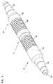
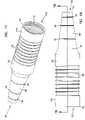
- FIG. 1is a perspective view of a pair of mated triaxial cable connectors with connector boots according to the present invention.
- FIG. 2is a side view of the pair of triaxial connectors with boots of FIG. 1 .
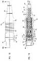
- FIG. 3is a cross-sectional view of the pair of triaxial connectors with boots of FIG. 1 , taken along line 3 — 3 in FIG. 2 .
- FIG. 6is a side view of the triaxial connector of FIG. 4 .
- FIG. 7is a cross-sectional view of the triaxial connector of FIG. 4 , taken along line 7 — 7 in FIG. 6 .
- FIG. 9is a side view of the protective boot of FIG. 8 .
- FIG. 11is a closer view of a lip along a distal end of the boot of FIG. 8 , corresponding with circle 11 of FIG. 10 .
- FIG. 12is a cross-sectional view of the triaxial connector of FIG. 7 , with the protective boot removed.
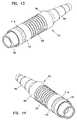
- FIG. 13is a first perspective view of the second of the pair of triaxial connectors of FIG. 1 , with the protective endcap of FIG. 4 .
- FIG. 14is a second perspective view of the triaxial connector of FIG. 13 .
- FIG. 15is a side view of the triaxial connector of FIG. 13 .
- FIG. 16is a cross-sectional view of the triaxial connector of FIG. 14 , taken along line 16 — 16 in FIG. 15 .
- FIG. 18is a side view of the protective boot of FIG. 17 .
- FIG. 19is a cross-sectional view of the protective boot of FIG. 17 , taken along line 19 — 19 in FIG. 18 .
- FIG. 21is a cross-section view of the triaxial connector of FIG. 16 , with the protective boot removed.
- FIG. 22is a perspective view of the protective endcap of FIG. 4 .
- FIG. 23is a side view of the protective endcap of FIG. 22 .
- FIG. 24is a cross-sectional view of the protective endcap of FIG. 22 , taken along line 24 — 24 in FIG. 23 .
- FIG. 25is an end view of the protective endcap of FIG. 22 .
- FIG. 26is a closer view of a lip along a first end of the protective endcap, corresponding to circle 26 in FIG. 24 .
- FIG. 28is an alternative embodiment endcap according to the present invention.
- Boots 54 and 56each include a grooved gripping surface 58 and a tapered cable end portion 60 with an opening 62 for a triaxial cable 64 (shown in FIG, 3 ) to extend from the connector within each boot.
- Gripping surface 58permits a user to securely grasp either connector 50 or 52 and exert proper axially tension on a locking mechanism of connector 40 or 42 to release the mating connectors of pair 51 .
- Such locking mechanismsare well known in the art and are described in U.S. Pat. Nos. 5,967,852; and 6,109,963; the disclosures of which are incorporated herein by reference.
- junction 66may preferably be water, air or dust resistant, or may be an area of engagement of boots 54 and 56 .
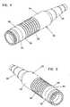
- connector assembly 50is shown with an endcap 78 engaging boot 54 at distal end 68 , forming a junction 80 .
- Junction 80is similar to junction 66 , shown in FIG. 3 , above, as endcap 78 is configured to engage boot 54 in the same manner as distal end 70 of boot 56 .
- Endcap 78includes a first end 84 adapted to fit about a mating end 44 of connector 40 .
- Endcap 78also includes an inwardly facing lip 90 which is configured to engage an outwardly facing lip 92 of distal end 68 of boot 54 to form junction 80 .
- FIGS. 8 to 11show boot 54 removed from about connector 40 .
- a connector opening 94is opposite from cable end 60 and allows entry through distal end 68 into an interior space 95 , where connector 40 may be positioned.
- Within interior space 95are a plurality of ridges 106 which cooperate with a mating plurality of grooves 108 about the locking mechanism of connector 40 (shown in FIG. 12 ). Ridges 106 and grooves 108 cooperate to permit a user to grasp gripping surface 58 about boot 54 of connector assembly 50 and retract the locking mechanism of connector 40 , permitting connector 40 to be disengaged from a mating connector, such as connector 42 .
- interior space 95 of boot 54includes an inner wall 110 , between grooves 106 and distal end 68 .
- Mating end 44 of connector 40extends within interior space 95 adjacent distal end 68 of boot 54 .
- first end 84 of endcap 78extends about mating end 44 and within inner wall 110 .
- endcap 78is fully inserted within connector assembly 50 such that lips 90 and 92 are engaged to form junction 80 , a first intermediate wall 112 within endcap 78 engages a distal end 45 of mating end 44 .
- First end 84is sized and configured to fit closely about mating end 44 so that endcap 78 may also be used with connector 40 which is not mounted within boot 54 .
- connector 42includes mating end 46 with a distal end 47 .
- Mating ends 44 and 46(shown in FIG. 12 , above) electrically and physically mate with each other with mating 44 inserted within mating 46 (as shown in FIG. 3 , above).
- second end 86 of endcap 78extends about mating end 46 and within inner wall 128 .
- endcap 78is fully inserted within connector assembly 52 such that inward facing lip 116 of boot 56 engages outward facing lip 120 of endcap 78 to form junction 114 , a second intermediate wall 118 within endcap 78 engages distal end 47 of mating end 46 .
- Second end 86is sized and configured to fit closely about mating end 46 so that endcap 78 may also be used with connector 42 which is not mounted within boot 56 . Junction 114 would not be formed, as there would be no inwardly facing lip 116 to engage outwardly facing lip 120 . However, endcap 78 would still be held securely and removably to mating end 46 of connector 42 by friction between second end 86 and mating end 46 . Second intermediate wall 120 of endcap 78 would also engage distal end 47 of mating end 46 .
- lips 92 and 116are shaped and configured to cooperatively engage each as shown in FIGS. 1 to 3 .
- Ridge 103 and groove 99receive and mate with groove 132 and ridge 130 , respectively, to form junction 66 .
- each of ridges 103 and 130 , and grooves 99 and 132are similarly shaped and sized. However, the shape and size of the ridges and grooves may be varied, provided that they cooperate to form junction 66 .
- Boots 54 and 56are made of rubber so that lips 92 and 116 may deform and pass across each other to engage corresponding grooves and ridges to form junction 66 , when the boots are mounted about connectors 40 and 42 in connector assemblies 50 and 52 , respectively. It is anticipated that other similar resilient, deformable materials that are electrically non-conductive, such as any of a variety of plastics, may be used as well.
- Second end 86includes a second open end 146 for receiving mating end 46 of connector 42 .
- Second open end 146is defined by an inner wall 158 , which is sized to fit closely about mating end 46 .
- Inner wall 158provides a friction fit of endcap 78 to connector 42 in the absence of boot 56 .
- Second inner wall 118is within a recess in a second inner face 152 of inner bulkhead 148 within second open end 146 .
- Between lip 90 and lip 120is an outer wall 160 , within which finger groove 82 is formed. As can be seen in FIGS. 6 and 15 , outer wall 160 and finger groove 82 are accessible when endcap 78 is positioned within either connector assembly 50 or 52 .
- endcap 78may also include a tether sized to fit about a boot or a connector. Such a tether would help prevent loss of endcaps and help ensure that an endcap is available when a cable is disconnected. Such a tether would also aid use of endcap 78 with a bulkhead type of triaxial connector, such as that described in commonly owned U.S. patent application Ser. No. 10/640,472, the disclosure of which is incorporated herein by reference.
- a tethered endcap 278is shown in FIG. 28 , and includes a body 280 which is similar to endcap 78 and a tether 282 with an opening 284 .
- Opening 284is sized to fit about an outer diameter of a triaxial connector such as connectors 40 and 42 , or about an outer diameter of a connector assembly with a protective boot, such as connector assemblies 50 and 52 .
- tether 282could be integrally formed as part of either boot 54 or 56 , so that endcap 278 is permanently attached to the boot.
Landscapes
- Connector Housings Or Holding Contact Members (AREA)
- Details Of Connecting Devices For Male And Female Coupling (AREA)
Abstract
Description
Claims (12)
Priority Applications (8)
| Application Number | Priority Date | Filing Date | Title |
|---|---|---|---|
| US10/775,759US7090516B2 (en) | 2004-02-09 | 2004-02-09 | Protective boot and universal cap |
| PCT/US2005/004489WO2005078865A2 (en) | 2004-02-09 | 2005-02-08 | Protective boot and universal cap |
| CA002553493ACA2553493A1 (en) | 2004-02-09 | 2005-02-08 | Protective boot and universal cap |
| EP05713431AEP1719212A2 (en) | 2004-02-09 | 2005-02-08 | Protective boot and universal cap |
| CN2005800044827ACN1918750B (en) | 2004-02-09 | 2005-02-08 | Protective boot and universal cap |
| US11/488,445US7226300B2 (en) | 2004-02-09 | 2006-07-17 | Protective boot and universal cap |
| US11/789,631US7407412B2 (en) | 2004-02-09 | 2007-04-25 | Protective boot and universal cap |
| US12/181,777US7674121B2 (en) | 2004-02-09 | 2008-07-29 | Protective boot and universal cap |
Applications Claiming Priority (1)
| Application Number | Priority Date | Filing Date | Title |
|---|---|---|---|
| US10/775,759US7090516B2 (en) | 2004-02-09 | 2004-02-09 | Protective boot and universal cap |
Related Child Applications (1)
| Application Number | Title | Priority Date | Filing Date |
|---|---|---|---|
| US11/488,445DivisionUS7226300B2 (en) | 2004-02-09 | 2006-07-17 | Protective boot and universal cap |
Publications (2)
| Publication Number | Publication Date |
|---|---|
| US20050176279A1 US20050176279A1 (en) | 2005-08-11 |
| US7090516B2true US7090516B2 (en) | 2006-08-15 |
Family
ID=34827273
Family Applications (4)
| Application Number | Title | Priority Date | Filing Date |
|---|---|---|---|
| US10/775,759Expired - Fee RelatedUS7090516B2 (en) | 2004-02-09 | 2004-02-09 | Protective boot and universal cap |
| US11/488,445Expired - Fee RelatedUS7226300B2 (en) | 2004-02-09 | 2006-07-17 | Protective boot and universal cap |
| US11/789,631Expired - Fee RelatedUS7407412B2 (en) | 2004-02-09 | 2007-04-25 | Protective boot and universal cap |
| US12/181,777Expired - LifetimeUS7674121B2 (en) | 2004-02-09 | 2008-07-29 | Protective boot and universal cap |
Family Applications After (3)
| Application Number | Title | Priority Date | Filing Date |
|---|---|---|---|
| US11/488,445Expired - Fee RelatedUS7226300B2 (en) | 2004-02-09 | 2006-07-17 | Protective boot and universal cap |
| US11/789,631Expired - Fee RelatedUS7407412B2 (en) | 2004-02-09 | 2007-04-25 | Protective boot and universal cap |
| US12/181,777Expired - LifetimeUS7674121B2 (en) | 2004-02-09 | 2008-07-29 | Protective boot and universal cap |
Country Status (5)
| Country | Link |
|---|---|
| US (4) | US7090516B2 (en) |
| EP (1) | EP1719212A2 (en) |
| CN (1) | CN1918750B (en) |
| CA (1) | CA2553493A1 (en) |
| WO (1) | WO2005078865A2 (en) |
Cited By (6)
| Publication number | Priority date | Publication date | Assignee | Title |
|---|---|---|---|---|
| US20090117762A1 (en)* | 2004-02-09 | 2009-05-07 | Adc Telecommunications, Inc. | Protective boot and universal cap |
| US20120063723A1 (en)* | 2010-09-10 | 2012-03-15 | Miniflex Limited | Optical fibre connector |
| US9461393B2 (en) | 2014-04-25 | 2016-10-04 | Covidien Lp | Physical shielding for ECG electrical connections |
| US20170104323A1 (en)* | 2015-10-12 | 2017-04-13 | Commscope Technologies Llc | Sealing boot for electrical interconnection |
| US20190190181A1 (en)* | 2017-12-14 | 2019-06-20 | Micro-Epsilon Messtechnik Gmbh & Co. Kg | Electrical plug connector |
| US10847925B2 (en)* | 2010-04-14 | 2020-11-24 | John Mezzalingua Associates, LLC | Cable connector cover |
Families Citing this family (34)
| Publication number | Priority date | Publication date | Assignee | Title |
|---|---|---|---|---|
| US6575786B1 (en)* | 2002-01-18 | 2003-06-10 | Adc Telecommunications, Inc. | Triaxial connector and method |
| US7442077B2 (en)* | 2003-06-17 | 2008-10-28 | Icp Global Technologies, Inc. | Modular cable system for solar power sources |
| WO2007010097A1 (en)* | 2005-07-21 | 2007-01-25 | Fci | Device for protecting connectors |
| TWM310501U (en)* | 2006-11-07 | 2007-04-21 | Tai Sol Electronics Co Ltd | Drawer-type electric card connector |
| US7632141B2 (en)* | 2007-02-22 | 2009-12-15 | John Mezzalingua Associates, Inc. | Compact compression connector with attached moisture seal |
| FR2916909B1 (en)* | 2007-05-30 | 2009-08-07 | Sagem Defense Securite | DEVICE FOR PROTECTING THE EMBOITABLE ELEMENTS OF A CONNECTOR |
| US7618276B2 (en)* | 2007-06-20 | 2009-11-17 | Amphenol Corporation | Connector assembly with gripping sleeve |
| US7544094B1 (en) | 2007-12-20 | 2009-06-09 | Amphenol Corporation | Connector assembly with gripping sleeve |
| US7946199B2 (en)* | 2008-07-27 | 2011-05-24 | The Jumper Shop, Llc | Coaxial cable connector nut rotation aid |
| US8109789B2 (en)* | 2008-12-12 | 2012-02-07 | Tyco Electronics Corporation | Connector assembly with strain relief |
| US8853542B2 (en) | 2009-03-30 | 2014-10-07 | John Mezzalingua Associates, LLC | Collar for sealingly engaging a cover for cable connectors |
| US8419467B2 (en)* | 2010-04-14 | 2013-04-16 | John Mezzalingua Associates, Inc. | Cover for cable connectors |
| US7771221B1 (en)* | 2009-09-27 | 2010-08-10 | Blackwell Donald A | Environmental protective covering for electrical power connectors |
| US8529288B2 (en) | 2010-04-14 | 2013-09-10 | John Mezzalingua Associates, LLC | Cover for cable connectors |
| WO2012044304A1 (en) | 2010-09-30 | 2012-04-05 | Molex Incorporated | Receptacle connector |
| US7914306B1 (en)* | 2010-10-11 | 2011-03-29 | Donald A. Blackwell | Environmental protective covering for universal serial bus connectors |
| CN103477098B (en)* | 2011-04-25 | 2018-01-12 | 株式会社海德世 | control cable |
| CN102364754B (en)* | 2011-10-17 | 2013-09-04 | 中国电子科技集团公司第四十研究所 | High-voltage connector assembly suitable for being used in satellite |
| US9216530B2 (en) | 2012-10-08 | 2015-12-22 | Commscope Technologies Llc | Connector cover |
| US9616602B2 (en) | 2013-07-10 | 2017-04-11 | Commscope Technologies Llc | Interconnection seal |
| US9444205B2 (en)* | 2014-03-25 | 2016-09-13 | Lear Corporation | Electric connector with contact protection |
| USD815046S1 (en) | 2016-08-30 | 2018-04-10 | Steren Electronics International, Llc | Sleeve for cable connector |
| US9837777B1 (en) | 2016-08-30 | 2017-12-05 | Steren Electronics International, Llc | Expandable cable connector torque adapter |
| DE102017214938B4 (en)* | 2016-08-31 | 2020-09-03 | Mando Corporation | Electronic parking brake |
| US9929499B2 (en) | 2016-09-01 | 2018-03-27 | Amphenol Corporation | Connector assembly with torque sleeve |
| US9929498B2 (en) | 2016-09-01 | 2018-03-27 | Times Fiber Communications, Inc. | Connector assembly with torque sleeve |
| CN106299766B (en)* | 2016-10-25 | 2018-08-28 | 宁波卓新通讯接插件有限公司 | A kind of one-to-many communication cable connector |
| CN106405769B (en)* | 2016-11-21 | 2018-06-26 | 金信诺(常州)轨道信号系统科技有限公司 | Wire jumper end part seal protective device |
| AU2018285692B2 (en)* | 2017-06-16 | 2023-01-19 | John Mezzalingua Associates, LLC | Weather protecting (WP) boot for coaxial cable connectors |
| US10340628B2 (en)* | 2017-09-21 | 2019-07-02 | Appleton Grp Llc | Cap for covering a plug opening |
| US10697567B2 (en)* | 2017-09-25 | 2020-06-30 | Baker Hughes, A Ge Company, Llc | Flexible device and method |
| CN112054338A (en)* | 2019-06-05 | 2020-12-08 | 康普技术有限责任公司 | Shroud and Connector Assembly |
| EP4038701A4 (en)* | 2019-10-01 | 2023-11-01 | CommScope Technologies LLC | Ganged coaxial connector assembly |
| CA3065707A1 (en) | 2019-12-20 | 2021-06-20 | Quanta Associates, L.P. | Implosion shield apparatus and method |
Citations (20)
| Publication number | Priority date | Publication date | Assignee | Title |
|---|---|---|---|---|
| US4030850A (en) | 1976-08-02 | 1977-06-21 | The United States Of America As Represented By The Secretary Of The Army | Interlocked joint |
| US4707043A (en) | 1986-11-03 | 1987-11-17 | Reed Charlie C | Electrical connector |
| GB2203297A (en) | 1987-04-02 | 1988-10-12 | Oxley Dev Co Ltd | High voltage connector |
| DE3735038A1 (en) | 1987-10-16 | 1989-04-27 | Philips Patentverwaltung | ON A PLUG OR A COUPLING OF A PLUG CONNECTABLE CAP |
| US5199893A (en)* | 1991-07-22 | 1993-04-06 | Fussell Don L | Seismic connector with replaceable seal |
| FR2725080A1 (en) | 1994-09-22 | 1996-03-29 | Porte Hubert Michel Marie | Connector for very low voltage linking optical contact to cable |
| DE29608939U1 (en) | 1995-08-25 | 1996-07-11 | GMZ Geräte-Meßvorrichtungen-Zubehör Handels-GmbH, 51766 Engelskirchen | Plug for an electric line |
| US5605468A (en)* | 1995-11-22 | 1997-02-25 | Tescorp Seismic Products, Inc. | Electrical connector assembly having replaceable sleeve seal |
| US5631443A (en) | 1995-05-30 | 1997-05-20 | Scrimpshire; James M. | Interference suppressing cable boot assembly |
| US5769662A (en)* | 1996-04-09 | 1998-06-23 | Augat Inc. | Snap together coaxial cable connector for use with polyethylene jacketed cable |
| US5886294A (en) | 1995-05-30 | 1999-03-23 | Scrimpshire; James Michael | Interference suppressing cable boot assembly |
| US5967852A (en) | 1998-01-15 | 1999-10-19 | Adc Telecommunications, Inc. | Repairable connector and method |
| US6065981A (en)* | 1998-02-03 | 2000-05-23 | Sopotnick; David F. | Marine power cord cover |
| US6511339B1 (en)* | 2001-08-31 | 2003-01-28 | Hon Hai Precision Ind. Co., Ltd. | Cable connector assembly with push lock |
| WO2003021720A1 (en) | 2001-09-04 | 2003-03-13 | Woodhead Industries, Inc. | Vibration resistant electrical connector |
| US6539161B2 (en) | 2001-03-16 | 2003-03-25 | Adc Telecommunications, Inc. | Cable routing clip |
| US6561848B1 (en) | 2002-01-18 | 2003-05-13 | Adc Telecommunications, Inc. | Triaxial connector adapter and method |
| US6575786B1 (en) | 2002-01-18 | 2003-06-10 | Adc Telecommunications, Inc. | Triaxial connector and method |
| US20030207601A1 (en)* | 2002-05-01 | 2003-11-06 | Hataya Mfg. Co., Ltd. | Socket |
| US6846988B2 (en) | 2002-01-18 | 2005-01-25 | Adc Telecommunications, Inc. | Triaxial connector including cable clamp |
Family Cites Families (26)
| Publication number | Priority date | Publication date | Assignee | Title |
|---|---|---|---|---|
| US3124405A (en)* | 1964-03-10 | Underwater separable connector | ||
| US3611255A (en)* | 1969-11-19 | 1971-10-05 | Lyall Electric | Moisture resistant electrical connector |
| US4609247A (en)* | 1983-07-11 | 1986-09-02 | Houston Geophysical Products, Inc. | Connector having two seal-rings of different diameters |
| US5300813A (en)* | 1992-02-26 | 1994-04-05 | International Business Machines Corporation | Refractory metal capped low resistivity metal conductor lines and vias |
| US5739579A (en)* | 1992-06-29 | 1998-04-14 | Intel Corporation | Method for forming interconnections for semiconductor fabrication and semiconductor device having such interconnections |
| US5595497A (en)* | 1995-03-01 | 1997-01-21 | Tescorp Seismic Products, Inc. | Underwater electrical connector |
| US5885098A (en)* | 1997-09-12 | 1999-03-23 | Phillips & Temro Industries Inc. | Cord set receptacle |
| US6114242A (en)* | 1997-12-05 | 2000-09-05 | Taiwan Semiconductor Manufacturing Company | MOCVD molybdenum nitride diffusion barrier for Cu metallization |
| US6249055B1 (en)* | 1998-02-03 | 2001-06-19 | Advanced Micro Devices, Inc. | Self-encapsulated copper metallization |
| US6111301A (en)* | 1998-04-24 | 2000-08-29 | International Business Machines Corporation | Interconnection with integrated corrosion stop |
| JP2000036346A (en)* | 1998-07-16 | 2000-02-02 | Sumitomo Wiring Syst Ltd | Connector for electric connections |
| JP3065582U (en)* | 1999-05-26 | 2000-02-02 | 木谷電器株式会社 | Power connector for photovoltaic power generator |
| US6248665B1 (en)* | 1999-07-06 | 2001-06-19 | Taiwan Semiconductor Manufacturing Company | Delamination improvement between Cu and dielectrics for damascene process |
| US6670266B2 (en)* | 2000-03-07 | 2003-12-30 | Simplus Systems Corporation | Multilayered diffusion barrier structure for improving adhesion property |
| US6495449B1 (en)* | 2000-03-07 | 2002-12-17 | Simplus Systems Corporation | Multilayered diffusion barrier structure for improving adhesion property |
| US6372636B1 (en)* | 2000-06-05 | 2002-04-16 | Chartered Semiconductor Manufacturing Ltd. | Composite silicon-metal nitride barrier to prevent formation of metal fluorides in copper damascene |
| US20020171147A1 (en)* | 2001-05-15 | 2002-11-21 | Tri-Rung Yew | Structure of a dual damascene via |
| TW518680B (en)* | 2001-06-13 | 2003-01-21 | Matsushita Electric Industrial Co Ltd | Semiconductor device and method for fabricating the same |
| US6900119B2 (en)* | 2001-06-28 | 2005-05-31 | Micron Technology, Inc. | Agglomeration control using early transition metal alloys |
| US6713373B1 (en)* | 2002-02-05 | 2004-03-30 | Novellus Systems, Inc. | Method for obtaining adhesion for device manufacture |
| US20040121583A1 (en)* | 2002-12-19 | 2004-06-24 | Taiwan Semiconductor Manufacturing Co., Ltd. | Method for forming capping barrier layer over copper feature |
| DE10303925B4 (en)* | 2003-01-31 | 2007-06-06 | Advanced Micro Devices, Inc., Sunnyvale | Dielectric barrier layer for a copper metallization layer having a silicon concentration varying over the thickness and method of manufacturing the same |
| US6753607B1 (en)* | 2003-05-19 | 2004-06-22 | Taiwan Semiconductor Manufacturing Co., Ltd. | Structure for improving interlevel conductor connections |
| US7090516B2 (en) | 2004-02-09 | 2006-08-15 | Adc Telecommunications, Inc. | Protective boot and universal cap |
| US6955563B1 (en)* | 2005-02-08 | 2005-10-18 | Croan Quinn F | RJ type modular connector for coaxial cables |
| US7189097B2 (en)* | 2005-02-11 | 2007-03-13 | Winchester Electronics Corporation | Snap lock connector |
- 2004
- 2004-02-09USUS10/775,759patent/US7090516B2/ennot_activeExpired - Fee Related
- 2005
- 2005-02-08EPEP05713431Apatent/EP1719212A2/ennot_activeWithdrawn
- 2005-02-08WOPCT/US2005/004489patent/WO2005078865A2/enactiveApplication Filing
- 2005-02-08CACA002553493Apatent/CA2553493A1/ennot_activeAbandoned
- 2005-02-08CNCN2005800044827Apatent/CN1918750B/ennot_activeExpired - Fee Related
- 2006
- 2006-07-17USUS11/488,445patent/US7226300B2/ennot_activeExpired - Fee Related
- 2007
- 2007-04-25USUS11/789,631patent/US7407412B2/ennot_activeExpired - Fee Related
- 2008
- 2008-07-29USUS12/181,777patent/US7674121B2/ennot_activeExpired - Lifetime
Patent Citations (22)
| Publication number | Priority date | Publication date | Assignee | Title |
|---|---|---|---|---|
| US4030850A (en) | 1976-08-02 | 1977-06-21 | The United States Of America As Represented By The Secretary Of The Army | Interlocked joint |
| US4707043A (en) | 1986-11-03 | 1987-11-17 | Reed Charlie C | Electrical connector |
| GB2203297A (en) | 1987-04-02 | 1988-10-12 | Oxley Dev Co Ltd | High voltage connector |
| DE3735038A1 (en) | 1987-10-16 | 1989-04-27 | Philips Patentverwaltung | ON A PLUG OR A COUPLING OF A PLUG CONNECTABLE CAP |
| US5199893A (en)* | 1991-07-22 | 1993-04-06 | Fussell Don L | Seismic connector with replaceable seal |
| FR2725080A1 (en) | 1994-09-22 | 1996-03-29 | Porte Hubert Michel Marie | Connector for very low voltage linking optical contact to cable |
| US5886294A (en) | 1995-05-30 | 1999-03-23 | Scrimpshire; James Michael | Interference suppressing cable boot assembly |
| US5631443A (en) | 1995-05-30 | 1997-05-20 | Scrimpshire; James M. | Interference suppressing cable boot assembly |
| DE29608939U1 (en) | 1995-08-25 | 1996-07-11 | GMZ Geräte-Meßvorrichtungen-Zubehör Handels-GmbH, 51766 Engelskirchen | Plug for an electric line |
| US5605468A (en)* | 1995-11-22 | 1997-02-25 | Tescorp Seismic Products, Inc. | Electrical connector assembly having replaceable sleeve seal |
| US5769662A (en)* | 1996-04-09 | 1998-06-23 | Augat Inc. | Snap together coaxial cable connector for use with polyethylene jacketed cable |
| US6109963A (en) | 1998-01-15 | 2000-08-29 | Adc Telecommunications, Inc. | Repairable connector and method |
| US5967852A (en) | 1998-01-15 | 1999-10-19 | Adc Telecommunications, Inc. | Repairable connector and method |
| US6065981A (en)* | 1998-02-03 | 2000-05-23 | Sopotnick; David F. | Marine power cord cover |
| US6539161B2 (en) | 2001-03-16 | 2003-03-25 | Adc Telecommunications, Inc. | Cable routing clip |
| US6665484B2 (en) | 2001-03-16 | 2003-12-16 | Adc Telecommunications, Inc. | Cable clip |
| US6511339B1 (en)* | 2001-08-31 | 2003-01-28 | Hon Hai Precision Ind. Co., Ltd. | Cable connector assembly with push lock |
| WO2003021720A1 (en) | 2001-09-04 | 2003-03-13 | Woodhead Industries, Inc. | Vibration resistant electrical connector |
| US6561848B1 (en) | 2002-01-18 | 2003-05-13 | Adc Telecommunications, Inc. | Triaxial connector adapter and method |
| US6575786B1 (en) | 2002-01-18 | 2003-06-10 | Adc Telecommunications, Inc. | Triaxial connector and method |
| US6846988B2 (en) | 2002-01-18 | 2005-01-25 | Adc Telecommunications, Inc. | Triaxial connector including cable clamp |
| US20030207601A1 (en)* | 2002-05-01 | 2003-11-06 | Hataya Mfg. Co., Ltd. | Socket |
Non-Patent Citations (1)
| Title |
|---|
| Canford Audio, Online Product Catalog, 2 pages (Undated). |
Cited By (11)
| Publication number | Priority date | Publication date | Assignee | Title |
|---|---|---|---|---|
| US20090117762A1 (en)* | 2004-02-09 | 2009-05-07 | Adc Telecommunications, Inc. | Protective boot and universal cap |
| US7674121B2 (en) | 2004-02-09 | 2010-03-09 | Adc Telecommunications, Inc. | Protective boot and universal cap |
| US10847925B2 (en)* | 2010-04-14 | 2020-11-24 | John Mezzalingua Associates, LLC | Cable connector cover |
| US20120063723A1 (en)* | 2010-09-10 | 2012-03-15 | Miniflex Limited | Optical fibre connector |
| US9461393B2 (en) | 2014-04-25 | 2016-10-04 | Covidien Lp | Physical shielding for ECG electrical connections |
| US20170104323A1 (en)* | 2015-10-12 | 2017-04-13 | Commscope Technologies Llc | Sealing boot for electrical interconnection |
| US10090661B2 (en)* | 2015-10-12 | 2018-10-02 | Commscope Technologies Llc | Sealing boot for electrical interconnection |
| US10270238B2 (en)* | 2015-10-12 | 2019-04-23 | Commscope Technologies Llc | Sealing boot for electrical interconnection |
| US10742014B2 (en)* | 2015-10-12 | 2020-08-11 | Commscope Technologies Llc | Sealing boot for electrical interconnection |
| US20190190181A1 (en)* | 2017-12-14 | 2019-06-20 | Micro-Epsilon Messtechnik Gmbh & Co. Kg | Electrical plug connector |
| US11095061B2 (en)* | 2017-12-14 | 2021-08-17 | Micro-Epsilon Messtechnik Gmbh & Co. Kg | Electrical plug connector |
Also Published As
| Publication number | Publication date |
|---|---|
| CA2553493A1 (en) | 2005-08-25 |
| WO2005078865A3 (en) | 2006-04-20 |
| CN1918750B (en) | 2010-09-01 |
| EP1719212A2 (en) | 2006-11-08 |
| WO2005078865A2 (en) | 2005-08-25 |
| US7226300B2 (en) | 2007-06-05 |
| US20050176279A1 (en) | 2005-08-11 |
| US7674121B2 (en) | 2010-03-09 |
| US7407412B2 (en) | 2008-08-05 |
| US20070049078A1 (en) | 2007-03-01 |
| CN1918750A (en) | 2007-02-21 |
| US20090117762A1 (en) | 2009-05-07 |
| US20070202741A1 (en) | 2007-08-30 |
Similar Documents
| Publication | Publication Date | Title |
|---|---|---|
| US7090516B2 (en) | Protective boot and universal cap | |
| US5259782A (en) | Electrical connector jacket | |
| USRE41044E1 (en) | Connector capable of connecting to coaxial cable without using tool | |
| US10530088B2 (en) | Electrical connector and sleeve for electrical contact | |
| US7195505B1 (en) | Connector assembly | |
| US6767248B1 (en) | Connector for coaxial cable | |
| EP2301118B1 (en) | Connector arrangement | |
| CA2620752C (en) | Electrical connector and conductor assembly cover | |
| EP0082320A1 (en) | Electrical connector member | |
| US20100018742A1 (en) | Substantially transparent cable protector and cable protection system | |
| US5494457A (en) | Snagless strain relief | |
| US20110256750A1 (en) | Retainer system for electric cable couplers | |
| US6171132B1 (en) | Cover for cable connectors and the like | |
| CA2915714C (en) | Optical fiber furcation assembly and method | |
| EP0616389B1 (en) | Electrical connector | |
| US20110250779A1 (en) | Electrical connector lock | |
| US20020019175A1 (en) | Connector device and connection element | |
| US6478601B2 (en) | Cord connector | |
| CA2177446C (en) | Electrical device having adjustable clamping mechanism | |
| EP0364075B1 (en) | Wall outlet for a fiber optic connector assembly | |
| KR101296332B1 (en) | Rotation prevention and automatic locking structure of SMB Connector | |
| AU701876B2 (en) | Electrical plug attachment | |
| JP3048477U (en) | Device for connecting plug and receptacle in connector | |
| JPH0419871Y2 (en) | ||
| CA2129783A1 (en) | Electrical plug assembly with releasable locking mechanism |
Legal Events
| Date | Code | Title | Description |
|---|---|---|---|
| AS | Assignment | Owner name:ADC TELECOMMUNICATIOS, INC., MINNESOTA Free format text:ASSIGNMENT OF ASSIGNORS INTEREST;ASSIGNOR:KHEMAKHEM, M'HAMED ANIS;REEL/FRAME:015447/0841 Effective date:20040216 | |
| FPAY | Fee payment | Year of fee payment:4 | |
| FPAY | Fee payment | Year of fee payment:8 | |
| AS | Assignment | Owner name:TYCO ELECTRONICS SERVICES GMBH, SWITZERLAND Free format text:ASSIGNMENT OF ASSIGNORS INTEREST;ASSIGNOR:ADC TELECOMMUNICATIONS, INC.;REEL/FRAME:036060/0174 Effective date:20110930 | |
| AS | Assignment | Owner name:COMMSCOPE EMEA LIMITED, IRELAND Free format text:ASSIGNMENT OF ASSIGNORS INTEREST;ASSIGNOR:TYCO ELECTRONICS SERVICES GMBH;REEL/FRAME:036956/0001 Effective date:20150828 | |
| AS | Assignment | Owner name:COMMSCOPE TECHNOLOGIES LLC, NORTH CAROLINA Free format text:ASSIGNMENT OF ASSIGNORS INTEREST;ASSIGNOR:COMMSCOPE EMEA LIMITED;REEL/FRAME:037012/0001 Effective date:20150828 | |
| AS | Assignment | Owner name:JPMORGAN CHASE BANK, N.A., AS COLLATERAL AGENT, ILLINOIS Free format text:PATENT SECURITY AGREEMENT (TERM);ASSIGNOR:COMMSCOPE TECHNOLOGIES LLC;REEL/FRAME:037513/0709 Effective date:20151220 Owner name:JPMORGAN CHASE BANK, N.A., AS COLLATERAL AGENT, ILLINOIS Free format text:PATENT SECURITY AGREEMENT (ABL);ASSIGNOR:COMMSCOPE TECHNOLOGIES LLC;REEL/FRAME:037514/0196 Effective date:20151220 Owner name:JPMORGAN CHASE BANK, N.A., AS COLLATERAL AGENT, IL Free format text:PATENT SECURITY AGREEMENT (TERM);ASSIGNOR:COMMSCOPE TECHNOLOGIES LLC;REEL/FRAME:037513/0709 Effective date:20151220 Owner name:JPMORGAN CHASE BANK, N.A., AS COLLATERAL AGENT, IL Free format text:PATENT SECURITY AGREEMENT (ABL);ASSIGNOR:COMMSCOPE TECHNOLOGIES LLC;REEL/FRAME:037514/0196 Effective date:20151220 | |
| FEPP | Fee payment procedure | Free format text:MAINTENANCE FEE REMINDER MAILED (ORIGINAL EVENT CODE: REM.) | |
| LAPS | Lapse for failure to pay maintenance fees | Free format text:PATENT EXPIRED FOR FAILURE TO PAY MAINTENANCE FEES (ORIGINAL EVENT CODE: EXP.); ENTITY STATUS OF PATENT OWNER: LARGE ENTITY | |
| STCH | Information on status: patent discontinuation | Free format text:PATENT EXPIRED DUE TO NONPAYMENT OF MAINTENANCE FEES UNDER 37 CFR 1.362 | |
| FP | Expired due to failure to pay maintenance fee | Effective date:20180815 | |
| AS | Assignment | Owner name:COMMSCOPE, INC. OF NORTH CAROLINA, NORTH CAROLINA Free format text:RELEASE BY SECURED PARTY;ASSIGNOR:JPMORGAN CHASE BANK, N.A.;REEL/FRAME:048840/0001 Effective date:20190404 Owner name:ALLEN TELECOM LLC, ILLINOIS Free format text:RELEASE BY SECURED PARTY;ASSIGNOR:JPMORGAN CHASE BANK, N.A.;REEL/FRAME:048840/0001 Effective date:20190404 Owner name:COMMSCOPE TECHNOLOGIES LLC, NORTH CAROLINA Free format text:RELEASE BY SECURED PARTY;ASSIGNOR:JPMORGAN CHASE BANK, N.A.;REEL/FRAME:048840/0001 Effective date:20190404 Owner name:REDWOOD SYSTEMS, INC., NORTH CAROLINA Free format text:RELEASE BY SECURED PARTY;ASSIGNOR:JPMORGAN CHASE BANK, N.A.;REEL/FRAME:048840/0001 Effective date:20190404 Owner name:ANDREW LLC, NORTH CAROLINA Free format text:RELEASE BY SECURED PARTY;ASSIGNOR:JPMORGAN CHASE BANK, N.A.;REEL/FRAME:048840/0001 Effective date:20190404 Owner name:ALLEN TELECOM LLC, ILLINOIS Free format text:RELEASE BY SECURED PARTY;ASSIGNOR:JPMORGAN CHASE BANK, N.A.;REEL/FRAME:049260/0001 Effective date:20190404 Owner name:COMMSCOPE TECHNOLOGIES LLC, NORTH CAROLINA Free format text:RELEASE BY SECURED PARTY;ASSIGNOR:JPMORGAN CHASE BANK, N.A.;REEL/FRAME:049260/0001 Effective date:20190404 Owner name:ANDREW LLC, NORTH CAROLINA Free format text:RELEASE BY SECURED PARTY;ASSIGNOR:JPMORGAN CHASE BANK, N.A.;REEL/FRAME:049260/0001 Effective date:20190404 Owner name:REDWOOD SYSTEMS, INC., NORTH CAROLINA Free format text:RELEASE BY SECURED PARTY;ASSIGNOR:JPMORGAN CHASE BANK, N.A.;REEL/FRAME:049260/0001 Effective date:20190404 Owner name:COMMSCOPE, INC. OF NORTH CAROLINA, NORTH CAROLINA Free format text:RELEASE BY SECURED PARTY;ASSIGNOR:JPMORGAN CHASE BANK, N.A.;REEL/FRAME:049260/0001 Effective date:20190404 |