US7090090B2 - Container for microwave oven cooking - Google Patents
Container for microwave oven cookingDownload PDFInfo
- Publication number
- US7090090B2 US7090090B2US10/806,200US80620004AUS7090090B2US 7090090 B2US7090090 B2US 7090090B2US 80620004 AUS80620004 AUS 80620004AUS 7090090 B2US7090090 B2US 7090090B2
- Authority
- US
- United States
- Prior art keywords
- lid
- cap
- side wall
- recess
- steam
- Prior art date
- Legal status (The legal status is an assumption and is not a legal conclusion. Google has not performed a legal analysis and makes no representation as to the accuracy of the status listed.)
- Expired - Fee Related, expires
Links
- 238000010411cookingMethods0.000titleclaimsabstractdescription34
- 235000013305foodNutrition0.000claimsdescription31
- 238000009835boilingMethods0.000description8
- 239000007788liquidSubstances0.000description8
- 238000010438heat treatmentMethods0.000description7
- 239000000428dustSubstances0.000description4
- 239000004798oriented polystyreneSubstances0.000description3
- 239000002985plastic filmSubstances0.000description3
- 235000021067refined foodNutrition0.000description3
- 239000004033plasticSubstances0.000description2
- 229920003023plasticPolymers0.000description2
- XLYOFNOQVPJJNP-UHFFFAOYSA-NwaterSubstancesOXLYOFNOQVPJJNP-UHFFFAOYSA-N0.000description2
- 239000004743PolypropyleneSubstances0.000description1
- 230000005574cross-species transmissionEffects0.000description1
- 238000000034methodMethods0.000description1
- -1polypropylenePolymers0.000description1
- 229920001155polypropylenePolymers0.000description1
- 238000003856thermoformingMethods0.000description1
- 238000007666vacuum formingMethods0.000description1
- 238000010792warmingMethods0.000description1
Images


Classifications
- B—PERFORMING OPERATIONS; TRANSPORTING
- B65—CONVEYING; PACKING; STORING; HANDLING THIN OR FILAMENTARY MATERIAL
- B65D—CONTAINERS FOR STORAGE OR TRANSPORT OF ARTICLES OR MATERIALS, e.g. BAGS, BARRELS, BOTTLES, BOXES, CANS, CARTONS, CRATES, DRUMS, JARS, TANKS, HOPPERS, FORWARDING CONTAINERS; ACCESSORIES, CLOSURES, OR FITTINGS THEREFOR; PACKAGING ELEMENTS; PACKAGES
- B65D43/00—Lids or covers for rigid or semi-rigid containers
- B65D43/02—Removable lids or covers
- B65D43/0202—Removable lids or covers without integral tamper element
- B65D43/0204—Removable lids or covers without integral tamper element secured by snapping over beads or projections
- B65D43/021—Removable lids or covers without integral tamper element secured by snapping over beads or projections only on the inside, or a part turned to the inside, of the mouth
- B—PERFORMING OPERATIONS; TRANSPORTING
- B65—CONVEYING; PACKING; STORING; HANDLING THIN OR FILAMENTARY MATERIAL
- B65D—CONTAINERS FOR STORAGE OR TRANSPORT OF ARTICLES OR MATERIALS, e.g. BAGS, BARRELS, BOTTLES, BOXES, CANS, CARTONS, CRATES, DRUMS, JARS, TANKS, HOPPERS, FORWARDING CONTAINERS; ACCESSORIES, CLOSURES, OR FITTINGS THEREFOR; PACKAGING ELEMENTS; PACKAGES
- B65D81/00—Containers, packaging elements, or packages, for contents presenting particular transport or storage problems, or adapted to be used for non-packaging purposes after removal of contents
- B65D81/34—Containers, packaging elements, or packages, for contents presenting particular transport or storage problems, or adapted to be used for non-packaging purposes after removal of contents for packaging foodstuffs or other articles intended to be cooked or heated within the package
- B65D81/3446—Containers, packaging elements, or packages, for contents presenting particular transport or storage problems, or adapted to be used for non-packaging purposes after removal of contents for packaging foodstuffs or other articles intended to be cooked or heated within the package specially adapted to be heated by microwaves
- A—HUMAN NECESSITIES
- A47—FURNITURE; DOMESTIC ARTICLES OR APPLIANCES; COFFEE MILLS; SPICE MILLS; SUCTION CLEANERS IN GENERAL
- A47J—KITCHEN EQUIPMENT; COFFEE MILLS; SPICE MILLS; APPARATUS FOR MAKING BEVERAGES
- A47J36/00—Parts, details or accessories of cooking-vessels
- A47J36/02—Selection of specific materials, e.g. heavy bottoms with copper inlay or with insulating inlay
- A47J36/027—Cooking- or baking-vessels specially adapted for use in microwave ovens; Accessories therefor
- B—PERFORMING OPERATIONS; TRANSPORTING
- B65—CONVEYING; PACKING; STORING; HANDLING THIN OR FILAMENTARY MATERIAL
- B65D—CONTAINERS FOR STORAGE OR TRANSPORT OF ARTICLES OR MATERIALS, e.g. BAGS, BARRELS, BOTTLES, BOXES, CANS, CARTONS, CRATES, DRUMS, JARS, TANKS, HOPPERS, FORWARDING CONTAINERS; ACCESSORIES, CLOSURES, OR FITTINGS THEREFOR; PACKAGING ELEMENTS; PACKAGES
- B65D21/00—Nestable, stackable or joinable containers; Containers of variable capacity
- B65D21/02—Containers specially shaped, or provided with fittings or attachments, to facilitate nesting, stacking, or joining together
- B65D21/0237—Rigid or semi-rigid containers provided with a recess on their external surface for accommodating a smaller container
- B—PERFORMING OPERATIONS; TRANSPORTING
- B65—CONVEYING; PACKING; STORING; HANDLING THIN OR FILAMENTARY MATERIAL
- B65D—CONTAINERS FOR STORAGE OR TRANSPORT OF ARTICLES OR MATERIALS, e.g. BAGS, BARRELS, BOTTLES, BOXES, CANS, CARTONS, CRATES, DRUMS, JARS, TANKS, HOPPERS, FORWARDING CONTAINERS; ACCESSORIES, CLOSURES, OR FITTINGS THEREFOR; PACKAGING ELEMENTS; PACKAGES
- B65D81/00—Containers, packaging elements, or packages, for contents presenting particular transport or storage problems, or adapted to be used for non-packaging purposes after removal of contents
- B65D81/34—Containers, packaging elements, or packages, for contents presenting particular transport or storage problems, or adapted to be used for non-packaging purposes after removal of contents for packaging foodstuffs or other articles intended to be cooked or heated within the package
- B65D81/3446—Containers, packaging elements, or packages, for contents presenting particular transport or storage problems, or adapted to be used for non-packaging purposes after removal of contents for packaging foodstuffs or other articles intended to be cooked or heated within the package specially adapted to be heated by microwaves
- B65D81/3453—Rigid containers, e.g. trays, bottles, boxes, cups
- B—PERFORMING OPERATIONS; TRANSPORTING
- B65—CONVEYING; PACKING; STORING; HANDLING THIN OR FILAMENTARY MATERIAL
- B65D—CONTAINERS FOR STORAGE OR TRANSPORT OF ARTICLES OR MATERIALS, e.g. BAGS, BARRELS, BOTTLES, BOXES, CANS, CARTONS, CRATES, DRUMS, JARS, TANKS, HOPPERS, FORWARDING CONTAINERS; ACCESSORIES, CLOSURES, OR FITTINGS THEREFOR; PACKAGING ELEMENTS; PACKAGES
- B65D83/00—Containers or packages with special means for dispensing contents
- B65D83/14—Containers for dispensing liquid or semi-liquid contents by internal gaseous pressure, i.e. aerosol containers comprising propellant
- B65D83/70—Pressure relief devices
- H—ELECTRICITY
- H05—ELECTRIC TECHNIQUES NOT OTHERWISE PROVIDED FOR
- H05B—ELECTRIC HEATING; ELECTRIC LIGHT SOURCES NOT OTHERWISE PROVIDED FOR; CIRCUIT ARRANGEMENTS FOR ELECTRIC LIGHT SOURCES, IN GENERAL
- H05B6/00—Heating by electric, magnetic or electromagnetic fields
- H05B6/64—Heating using microwaves
- B—PERFORMING OPERATIONS; TRANSPORTING
- B65—CONVEYING; PACKING; STORING; HANDLING THIN OR FILAMENTARY MATERIAL
- B65D—CONTAINERS FOR STORAGE OR TRANSPORT OF ARTICLES OR MATERIALS, e.g. BAGS, BARRELS, BOTTLES, BOXES, CANS, CARTONS, CRATES, DRUMS, JARS, TANKS, HOPPERS, FORWARDING CONTAINERS; ACCESSORIES, CLOSURES, OR FITTINGS THEREFOR; PACKAGING ELEMENTS; PACKAGES
- B65D2543/00—Lids or covers essentially for box-like containers
- B65D2543/00009—Details of lids or covers for rigid or semi-rigid containers
- B65D2543/00018—Overall construction of the lid
- B65D2543/00064—Shape of the outer periphery
- B65D2543/00074—Shape of the outer periphery curved
- B65D2543/00092—Shape of the outer periphery curved circular
- B—PERFORMING OPERATIONS; TRANSPORTING
- B65—CONVEYING; PACKING; STORING; HANDLING THIN OR FILAMENTARY MATERIAL
- B65D—CONTAINERS FOR STORAGE OR TRANSPORT OF ARTICLES OR MATERIALS, e.g. BAGS, BARRELS, BOTTLES, BOXES, CANS, CARTONS, CRATES, DRUMS, JARS, TANKS, HOPPERS, FORWARDING CONTAINERS; ACCESSORIES, CLOSURES, OR FITTINGS THEREFOR; PACKAGING ELEMENTS; PACKAGES
- B65D2543/00—Lids or covers essentially for box-like containers
- B65D2543/00009—Details of lids or covers for rigid or semi-rigid containers
- B65D2543/00018—Overall construction of the lid
- B65D2543/00259—Materials used
- B65D2543/00296—Plastic
- B—PERFORMING OPERATIONS; TRANSPORTING
- B65—CONVEYING; PACKING; STORING; HANDLING THIN OR FILAMENTARY MATERIAL
- B65D—CONTAINERS FOR STORAGE OR TRANSPORT OF ARTICLES OR MATERIALS, e.g. BAGS, BARRELS, BOTTLES, BOXES, CANS, CARTONS, CRATES, DRUMS, JARS, TANKS, HOPPERS, FORWARDING CONTAINERS; ACCESSORIES, CLOSURES, OR FITTINGS THEREFOR; PACKAGING ELEMENTS; PACKAGES
- B65D2543/00—Lids or covers essentially for box-like containers
- B65D2543/00009—Details of lids or covers for rigid or semi-rigid containers
- B65D2543/00342—Central part of the lid
- B65D2543/00351—Dome-like
- B—PERFORMING OPERATIONS; TRANSPORTING
- B65—CONVEYING; PACKING; STORING; HANDLING THIN OR FILAMENTARY MATERIAL
- B65D—CONTAINERS FOR STORAGE OR TRANSPORT OF ARTICLES OR MATERIALS, e.g. BAGS, BARRELS, BOTTLES, BOXES, CANS, CARTONS, CRATES, DRUMS, JARS, TANKS, HOPPERS, FORWARDING CONTAINERS; ACCESSORIES, CLOSURES, OR FITTINGS THEREFOR; PACKAGING ELEMENTS; PACKAGES
- B65D2543/00—Lids or covers essentially for box-like containers
- B65D2543/00009—Details of lids or covers for rigid or semi-rigid containers
- B65D2543/00444—Contact between the container and the lid
- B65D2543/00481—Contact between the container and the lid on the inside or the outside of the container
- B65D2543/0049—Contact between the container and the lid on the inside or the outside of the container on the inside, or a part turned to the inside of the mouth of the container
- B65D2543/00509—Cup
- B—PERFORMING OPERATIONS; TRANSPORTING
- B65—CONVEYING; PACKING; STORING; HANDLING THIN OR FILAMENTARY MATERIAL
- B65D—CONTAINERS FOR STORAGE OR TRANSPORT OF ARTICLES OR MATERIALS, e.g. BAGS, BARRELS, BOTTLES, BOXES, CANS, CARTONS, CRATES, DRUMS, JARS, TANKS, HOPPERS, FORWARDING CONTAINERS; ACCESSORIES, CLOSURES, OR FITTINGS THEREFOR; PACKAGING ELEMENTS; PACKAGES
- B65D2543/00—Lids or covers essentially for box-like containers
- B65D2543/00009—Details of lids or covers for rigid or semi-rigid containers
- B65D2543/00444—Contact between the container and the lid
- B65D2543/00481—Contact between the container and the lid on the inside or the outside of the container
- B65D2543/00537—Contact between the container and the lid on the inside or the outside of the container on the outside, or a part turned to the outside of the mouth of the container
- B65D2543/00546—NO contact
- B—PERFORMING OPERATIONS; TRANSPORTING
- B65—CONVEYING; PACKING; STORING; HANDLING THIN OR FILAMENTARY MATERIAL
- B65D—CONTAINERS FOR STORAGE OR TRANSPORT OF ARTICLES OR MATERIALS, e.g. BAGS, BARRELS, BOTTLES, BOXES, CANS, CARTONS, CRATES, DRUMS, JARS, TANKS, HOPPERS, FORWARDING CONTAINERS; ACCESSORIES, CLOSURES, OR FITTINGS THEREFOR; PACKAGING ELEMENTS; PACKAGES
- B65D2543/00—Lids or covers essentially for box-like containers
- B65D2543/00009—Details of lids or covers for rigid or semi-rigid containers
- B65D2543/00444—Contact between the container and the lid
- B65D2543/00592—Snapping means
- B65D2543/00601—Snapping means on the container
- B65D2543/00611—Profiles
- B65D2543/0062—Groove or hollow bead
- B—PERFORMING OPERATIONS; TRANSPORTING
- B65—CONVEYING; PACKING; STORING; HANDLING THIN OR FILAMENTARY MATERIAL
- B65D—CONTAINERS FOR STORAGE OR TRANSPORT OF ARTICLES OR MATERIALS, e.g. BAGS, BARRELS, BOTTLES, BOXES, CANS, CARTONS, CRATES, DRUMS, JARS, TANKS, HOPPERS, FORWARDING CONTAINERS; ACCESSORIES, CLOSURES, OR FITTINGS THEREFOR; PACKAGING ELEMENTS; PACKAGES
- B65D2543/00—Lids or covers essentially for box-like containers
- B65D2543/00009—Details of lids or covers for rigid or semi-rigid containers
- B65D2543/00444—Contact between the container and the lid
- B65D2543/00592—Snapping means
- B65D2543/00601—Snapping means on the container
- B65D2543/00675—Periphery concerned
- B65D2543/00685—Totality
- B—PERFORMING OPERATIONS; TRANSPORTING
- B65—CONVEYING; PACKING; STORING; HANDLING THIN OR FILAMENTARY MATERIAL
- B65D—CONTAINERS FOR STORAGE OR TRANSPORT OF ARTICLES OR MATERIALS, e.g. BAGS, BARRELS, BOTTLES, BOXES, CANS, CARTONS, CRATES, DRUMS, JARS, TANKS, HOPPERS, FORWARDING CONTAINERS; ACCESSORIES, CLOSURES, OR FITTINGS THEREFOR; PACKAGING ELEMENTS; PACKAGES
- B65D2543/00—Lids or covers essentially for box-like containers
- B65D2543/00009—Details of lids or covers for rigid or semi-rigid containers
- B65D2543/00444—Contact between the container and the lid
- B65D2543/00592—Snapping means
- B65D2543/00712—Snapping means on the lid
- B65D2543/00722—Profiles
- B65D2543/00731—Groove or hollow bead
- B—PERFORMING OPERATIONS; TRANSPORTING
- B65—CONVEYING; PACKING; STORING; HANDLING THIN OR FILAMENTARY MATERIAL
- B65D—CONTAINERS FOR STORAGE OR TRANSPORT OF ARTICLES OR MATERIALS, e.g. BAGS, BARRELS, BOTTLES, BOXES, CANS, CARTONS, CRATES, DRUMS, JARS, TANKS, HOPPERS, FORWARDING CONTAINERS; ACCESSORIES, CLOSURES, OR FITTINGS THEREFOR; PACKAGING ELEMENTS; PACKAGES
- B65D2543/00—Lids or covers essentially for box-like containers
- B65D2543/00009—Details of lids or covers for rigid or semi-rigid containers
- B65D2543/00444—Contact between the container and the lid
- B65D2543/00592—Snapping means
- B65D2543/00712—Snapping means on the lid
- B65D2543/00787—Periphery concerned
- B65D2543/00796—Totality
Definitions
- This inventionrelates to a container for microwave oven cooking, and more particularly to a food container having a lid capable of automatically releasing heated expanded steam.
- Microwave ovensare conventionally used for convenient and easy heating of food and drink.
- a containermade of heat-resistant plastic sheet, and having a hermetically sealed lid, is widely used for microwave heating of fresh food as well as processed food.
- Food and drinkcan be packaged in such a container, and can be easily heated and cooked without removal of from the container.
- Known microwaveable containershaving hermetically sealed lids, and capable of withstanding temperatures of around 120° C., release expanded steam generated through a hole cut in the top or in the rim of the lid, or through a slit cut in a part of lid. Expanded steam may also be released through a concave groove in the fitting section of the body of the container when the lid is in place.
- Such a containeris described in Japanese Patent No. 3009863.
- the lidmay be forced off the container body by steam pressure, or liquid may splash out of the container through the concave groove in the fitting section, making a mess inside the microwave oven, reducing the amount of liquid in the container, and resulting in either inadequate or excessive cooking.
- Containers of the prior arthave a structure suitable for warming foods, but are generally unsuitable for cooking food when the container is filled with water or broth, which is generally a requirement for cooking fresh food.
- Small openings or the likemay be provided in a part of the container, but such openings may cause another problem in that they permit the entry of dust or dirt into the container.
- An object of this inventionis to overcome the above problems, and to provide a food container for microwave oven cooking, made of plastic sheet, in which processed food can be preserved and conveyed in a sealed condition, in which steam pressure can be controlled, which prevents broth from boiling over during heating and cooking, and which achieves a quality of cooking equivalent to that achieved using conventional cooking utensils such as a pot, a pressure cooker, or a caldron or the like, heated by a gas flame or an electric heater.
- the inventionachieves the same cooking result as achieved in conventional cooking when the heat is repeatedly adjusted from a high to a medium or low flame, and the position of the pot lid is adjusted relative to the pot in order to prevent broth from boiling over when food and broth, or cold or hot water are heated by conduction from a gas burner, electric element or the like.
- the container for microwave oven cookingin accordance with the invention comprises a main container body, a lid, and a cap providing an enclosure for containing food to be cooked.
- the main container bodyhas a bottom and a main body side wall extending upward from the bottom.
- the side wallhas a main body rim.
- the lidhas a lid top, and a lid side wall extending downward from the lid top.
- the lid side wallhas a lid rim engageable with the main body rim.
- the lidalso has a recess formed in the lid top, and the recess has an opening.
- the capis received in the recess of the lid, and has a cap bottom, and a cap side wall having at least one section conforming to the shape of a part of the side wall of the recess, and engageable with that part of the side wall of the recess so that, when the cap is in a lowermost position in the recess, the opening of the recess is closed by the cap.
- At least one steam-releasing grooveformed in the side wall of the recess, or in the cap side wall, provides a path for the release of steam from the enclosure when the cap is moved upward relative to the lid by steam pressure within the enclosure.
- the steam-releasing grooveis formed in the side wall of the recess, it is preferably step-shaped.
- the interengaging elementspreferably comprise an inwardly projecting annular projection formed on the side wall of the recess, and an outwardly projecting projection formed on the side wall of the cap.
- the inwardly projecting annular projectingoverlies, and is engageable with, the outwardly projecting projection when the cap is moved upward relative to the lid, and is spaced therefrom when the cap is in its lowermost position with the above-mentioned at least one section of the cap side wall engaged with the above-mentioned part of the side wall of the recess.
- Interengageable elementsmay also be provided on the main container body and lid for permitting and limiting upward movement of the lid relative to said main container body as a result of steam pressure in the enclosure, and the main container body said lid may form a gap for the release of steam when the lid is moved upward relative to said main container body.
- the main body rimpreferably comprises a shoulder extending laterally from the main body side wall, and a wall section extending upward from the shoulder at a location spaced laterally from the main body side wall.
- the rim of the lidcomprises a shoulder-engaging section engageable with the shoulder of the main body rim, and the wall section has a first lateral projection, and the lid has a second lateral projection underlying the first lateral projection, and spaced therefrom by a distance permitting limited upward movement of the lid relative to the main container body as a result of steam pressure.
- the height of the lidis at least as great as the height of the container main body and the bottom of the cap is concave when viewed from the bottom.
- the cap and/or the lidWhen steam pressure rises in the container, the cap and/or the lid automatically shift upward, and steam generated inside the container system is released through the lid opening and the steam-releasing groove or grooves, and/or through gap between a main container body and the lid.
- the lidis prevented from coming off the container as a result of steam pressure, and the boiling over of liquid, and a resultant mess inside the microwave oven, are also avoided.
- the pressure inside the containerfalls, and the cap returns automatically to the same closed condition as before cooking commenced, and the main body and lid are also fitted to each other just as they were before cooking commenced. Therefore, spillage of liquid is avoided, and the entry of dirt or dust into the container is also prevented.
- the container systemcan be produced easily. Its shape is relatively simple, and thus, it can be molded from plastics, and readily removed from the mold.
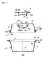
- FIG. 1is an exploded perspective view of a container system for microwave oven cooking according to a first embodiment of the invention
- FIG. 2is a cross-sectional view showing the three main components of the container system of FIG. 1 ;
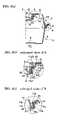
- FIG. 3( a )is a fragmentary cross-sectional view showing the components of FIG. 2 fitted together
- FIGS. 3( b ) and 3 ( c )are enlarged cross-sectional views showing details of parts seen in FIG. 3( a );
- FIGS. 4( a ) and 4 ( b )are enlarged cross-sectional views the cap of the container system respectively in an “up” position and in a “down” position;
- FIGS. 4( c ) and 4 ( d )are enlarged cross-sectional views the lid of the container system respectively in an “up” position and in a “down” position;
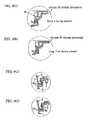
- FIGS. 5( a ) and 5 ( b )are enlarged cross-sectional views at the location of a lid steam-releasing groove, which show a cap respectively in its “up” and “down” positions;
- FIG. 6is an exploded perspective view of a container system for microwave oven cooking according to a second embodiment of invention.
- FIG. 7is a cross-sectional view showing the three main components of the container system of FIG. 1 ;
- FIG. 8( a )is a fragmentary cross-sectional view showing the components of FIG. 7 fitted together
- FIGS. 8( b ) and 8 ( c )are enlarged cross-sectional views showing details of parts seen in FIG. 8( a );
- FIGS. 9( a ) and 9 ( b )are enlarged cross-sectional views the cap of the container system of FIG. 7 respectively in an “up” position and in a “down” position;
- FIGS. 9( c ) and 9 ( d )are enlarged cross-sectional views the lid of the container system of FIG. 7 respectively in an “up” position and in a “down” position;
- FIGS. 10( a ) and 10 ( b )are enlarged cross-sectional views at the location of a lid steam-releasing groove in the container system of FIG. 7 , which show a cap respectively in its “up” and “down” positions;
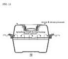
- FIG. 11is an explanatory schematic view illustrating the flow of steam in the case of a comparatively low steam pressure
- FIG. 12is an explanatory schematic view illustrating the flow of steam in the case of a comparatively high steam pressure
- FIG. 13is an explanatory schematic view illustrating the movement of broth and the flow of steam before the broth reaches its boiling point
- FIG. 14is an explanatory schematic view illustrating the movement of broth and the flow of steam after the broth reaches its boiling point.
- the container 10comprises a main body 1 , a lid 2 , and a cap 3 .
- the upper part of the main body 1has an annular internal shoulder, forming a fitting section 9 for receiving an annular lower part 13 of the lid 2 .
- a central recess 7is formed in the upper part of the lid for receiving the cap 3 .
- the caphas an annular cap fitting section 12 .
- the annular lower part 13 and the annular cap fitting section 12are respectively fitted into the fitting section 9 and the lid recess 7 .
- the lid recess 7has a central opening 8 and steam-releasing grooves 18 formed in its side wall.
- the recess 7is in the form of a stepped cone.
- the cap 3is received in recess 7 , and the annular lower part 13 on the bottom of the lid is received in the fitting section 9 in the upper part of the main body 1 , liquid is prevented from boiling over or spilling out.
- the height of the lid 2is equal to or greater than the height of the main body 1 , and the downward face of the bottom part 23 of the cap 3 is concave.
- the main body 1 , the lid 2 , and the cap 3may be formed by thermoforming methods such as pressure forming or vacuum forming, using plastic sheet with good heat resistance, such as oriented polystyrene (OPS), heat-resistant oriented polystyrene (heat-resistant OPS), or polypropylene.
- thermoforming methodssuch as pressure forming or vacuum forming, using plastic sheet with good heat resistance, such as oriented polystyrene (OPS), heat-resistant oriented polystyrene (heat-resistant OPS), or polypropylene.
- the opening 6 of the main body 1 of the containeris formed with a circumference slightly larger than the circumference of the container bottom 4 , and the container sidewall 5 is generally frusto-conical in shape.
- the fitting section 9which receives the annular lower part 13 of the lid, is provided by forming, on the upper part of the container wall 5 , an annular shoulder or tier 9 a , an annular side wall 9 b , and an inwardly projecting annular section 9 c .
- a flange 14extending outward from the fitting section 9 by an appropriate distance, can be either curved or flat, and preferably has a short, downwardly folded outer edge 17 .
- the shoulder or tier 9 awhich is engaged by the annular lower part 13 of the lid 2 , is preferably formed as a flat surface in order to fit the rim of the lid.
- the top 21 of lid 2is generally circular and the side wall 19 of the lid extends downward from the top 21 .
- the annular lower part 13comprises an engaging section 13 c , a wall section 13 b , a tier section 13 a , and a flange 15 .
- the wall section 13 bis folded upward from the engaging section 13 c in order to fit the side wall 9 b below the inwardly projecting annular section 9 c of the main body 1 .
- the lid tier section 13 a and the flange 15extend horizontally.
- the tier 9 ais continuous with, and extends outward from, the inner surface of wall 5 at the upper end of the wall.
- the tier 9 ahas a width sufficient to allow the annular lower part 13 of the lid 2 to be received thereon.
- the inwardly projecting annular section 9 cis located above, and spaced from, tier 9 a , by the height of side wall 9 b .
- the top of annular section 9 cdefines an opening the inside diameter of which is smaller than the outside diameter of the circumferential edge of the lid.
- the flange 14is continuous with, and extends outward from, the top of annular section 9 c .
- the lid 2 and a cap 3are formed to achieve automatic control of the pressure of the steam generated by heat in the container 10 .
- concave steam-releasing grooves 18are formed in the stepped, cone-shaped recess of the lid. These grooves extend from the surface 24 surrounding the lid opening 8 to the top of the lid, that is, from the lid tier 11 a 1 ( FIG.
- these tiers 11 a 1 , 11 a 2 , 11 a 3 , the wall sections 11 b 1 , 11 b 2 , and 11 b 3 , the annular projection 11 c , and the lid top 21closely fit sections of the cap, namely, a folded rim 22 , an engaging section 12 c , a wall section 12 b , a tier 12 a , and a flange 16 .
- the steamis released outward through the concave lid steam-releasing grooves 18 and through a gap between the cap flange 16 and the lid top 21 while the cap 3 fits into the lid 2 in the position shown in FIG. 4( b ).
- the amount of steam generated and its rate of expansionvary depending on the food content in the container 10 , and it is preferable not to have the cap 3 withstand 100% of the pressure, especially when it is applied suddenly due to the energy of the expanding steam.
- the side wall 9 b of the fitting section 9formed at the rim of the main container body 1 , is a few millimeters longer than the engaging section 13 c of the lid 2 . Consequently, the lid responds to the steam pressure by moving upward and downward relative to the container body 1 , and the force applied to the cap 3 is reduced.
- the container tier 9 awhen the lid 2 is fitted to the container body 1 , the container tier 9 a , the container wall section 9 b , the annular projection 9 c , and the container flange 14 , are closely fitted to the folded rim 20 of the lid (see FIG. 3( c )), the engaging section 13 c , the wall section 13 b , tier 13 a , and the lid flange 15 .
- FIGS. 6–10A second embodiment of a container system for microwave oven cooking according to the invention will be explained referring to FIGS. 6–10 . Where elements in the second embodiment are the same as those of the first embodiment, the same reference numerals are used, and explanation may be omitted.
- a container 101comprises a main body 1 , a lid 2 , and a cap 3 .
- the main body 1has a fitting section 9 in its upper part.
- the lid 2has a fitting section 13 in its lower part and a recess 7 in its upper part.
- steam release grooves 25are formed on the outside of the cap below the cap fitting section 12 , instead of in the wall of the recess as in the first embodiment.
- the fitting section 13 of the lid, and the fitting section 12 of the capare respectively fitted into the fitting section 9 and the lid recess 7 .
- the lid recess 7has a central opening 8 .
- the container according to the second embodimentnot only has a superior steam-releasing function, but also has the advantage that it may be produced more easily in comparison to the container of the first embodiment. Its shape is relatively simple, and the components are easier to remove from a mold.
- a lid 2 and a cap 3are formed to control the pressure of steam generated in container 101 .
- the steam-releasing grooves 25are formed with appropriate widths, being separated from one another by parts of the cap fitting section. It is desirable that the cap steam-releasing grooves 25 are arranged at uniform intervals on the outer side of a cap 3 .
- the steamis released outward through the concave steam-releasing grooves 25 in the cap, and through a gap between the cap flange 16 and a lid top 21 while the cap is fitted into the lid 2 as shown in FIG. 9 ( b ).
- the amount of steam and its expansion ratevary depending on the food content in the container, and it is preferable not to have the cap 3 withstand 100% of the pressure, especially when it is applied suddenly due to the energy of the expanding steam.
- the lid 2can move up and down relative to the main container body 1 . Consequently, the lid responds to the steam pressure by moving upward and downward relative to the container body 1 , and the force applied to the cap 3 is reduced.
- the wall section 11 b 1 of the lidis a few millimeters higher than the cap engaging section 12 c as shown in FIGS. 8( b ), 9 ( a ), 9 ( b ), 10 ( a ) and 10 ( b ).
- the steam passing through the central lid opening 8applies a force to the cap bottom 23 and moves the cap 3 upward by a few millimeters until the cap engaging section 12 c is stopped by engagement with the annular projection 11 c .
- the capis lifted in this manner, its flange 16 moves away from the lid top 21 , as shown in FIG. 9( a ), providing a larger aperture for the release of steam.
- FIGS. 11–14show a container according to the first embodiment, but applies as well to a container according to the second embodiment.
- FIG. 11shows the course of steam being released from the inside of a container 10 to the outside when the steam pressure is relatively small.
- FIG. 12shows the course of steam released from the inside of the container 10 when the steam pressure is relatively high.
- FIG. 13illustrates the splashing of liquid inside the container 10 , when the food or broth etc. is heated almost to the boiling point.
- FIG. 14illustrates the splashing of liquid inside the container when the food or broth etc. reaching the boiling point.
- the container according to the inventioncan be used not only to heat and cook foods with a large amount of broth, but can also be used to cook fresh food and processed food at the same time.
- the main body 1 and the lid 2 , and the lid 2 and the cap 3are respectively fitted so that they will not come apart suddenly, spillage of broth or food to the outside of the container, and entry of dust and dirt into the container, can be avoided.
- the cap and/or the lidautomatically shifts upwards, and steam generated inside the container is released. Therefore steam pressure is prevented from causing the lid to come off the container and allowing broth to boil over and make a mess inside the microwave oven.
- the capautomatically returns to the same fitting relationship to the lid that it was in before cooking commenced.
- the main body and the lid, and the lid and the capare respectively connected at their fitting sections as before cooking. Therefore, the container exhibits an outstanding ability to prevent broth or other liquid from spilling out of the container and an outstanding ability to prevent dirt or dust from entering the container, and contaminating the food therein.
- the container systemespecially the container system according to the second embodiment of the invention, can be produced easily, since its shape is relatively simple, and its components can be easily molded from plastics and easily removed from the mold.
Landscapes
- Engineering & Computer Science (AREA)
- Mechanical Engineering (AREA)
- Food Science & Technology (AREA)
- Life Sciences & Earth Sciences (AREA)
- Chemical & Material Sciences (AREA)
- Electromagnetism (AREA)
- Physics & Mathematics (AREA)
- Dispersion Chemistry (AREA)
- Cookers (AREA)
- Constitution Of High-Frequency Heating (AREA)
- Packages (AREA)
- Package Specialized In Special Use (AREA)
- Closures For Containers (AREA)
- Electric Ovens (AREA)
Abstract
Description
Claims (10)
Applications Claiming Priority (4)
| Application Number | Priority Date | Filing Date | Title |
|---|---|---|---|
| JP80257/2003 | 2003-03-24 | ||
| JP2003080257 | 2003-03-24 | ||
| JP2004000509AJP3962377B2 (en) | 2003-03-24 | 2004-01-05 | Microwave cooking system container |
| JP509/2004 | 2004-01-05 |
Publications (2)
| Publication Number | Publication Date |
|---|---|
| US20040188442A1 US20040188442A1 (en) | 2004-09-30 |
| US7090090B2true US7090090B2 (en) | 2006-08-15 |
Family
ID=32852738
Family Applications (1)
| Application Number | Title | Priority Date | Filing Date |
|---|---|---|---|
| US10/806,200Expired - Fee RelatedUS7090090B2 (en) | 2003-03-24 | 2004-03-22 | Container for microwave oven cooking |
Country Status (14)
| Country | Link |
|---|---|
| US (1) | US7090090B2 (en) |
| EP (1) | EP1464262B1 (en) |
| JP (1) | JP3962377B2 (en) |
| KR (1) | KR100645981B1 (en) |
| CN (1) | CN1234583C (en) |
| AT (1) | ATE300222T1 (en) |
| CA (1) | CA2461767C (en) |
| DE (1) | DE602004000038T2 (en) |
| DK (1) | DK1464262T3 (en) |
| ES (1) | ES2246053T3 (en) |
| MY (1) | MY136963A (en) |
| PL (1) | PL1464262T3 (en) |
| PT (1) | PT1464262E (en) |
| TW (1) | TWI232092B (en) |
Cited By (30)
| Publication number | Priority date | Publication date | Assignee | Title |
|---|---|---|---|---|
| US20060000842A1 (en)* | 2004-06-30 | 2006-01-05 | Maxwell Jason R | Ventable container assembly |
| US20080087673A1 (en)* | 2006-10-17 | 2008-04-17 | Meyer Intellectual Properties Limited | Cookware with Multiple Component Lid |
| USD594328S1 (en) | 2008-02-29 | 2009-06-16 | Conagra Foods Rdm, Inc. | Container cover |
| USD610903S1 (en) | 2007-03-02 | 2010-03-02 | Conagra Foods Rdm, Inc. | Container assembly |
| USD635817S1 (en) | 2006-06-09 | 2011-04-12 | Conagra Foods Rdm, Inc. | Container assembly |
| USD638701S1 (en) | 2010-09-08 | 2011-05-31 | Conagra Foods Rdm, Inc. | Container |
| USD639186S1 (en) | 2010-09-08 | 2011-06-07 | Conagra Foods Rdm, Inc. | Container with sleeve |
| USD639656S1 (en) | 2010-09-08 | 2011-06-14 | Con Agra Foods RDM, Inc. | Container lid |
| US8071923B2 (en) | 2007-02-15 | 2011-12-06 | Mcmahan Enterprises, Llc | Device for microwave heating of a food product |
| US20120024859A1 (en)* | 2010-07-30 | 2012-02-02 | Francesco Longoni | Container |
| US20120118889A1 (en)* | 2009-02-20 | 2012-05-17 | Crown Packaging Technology, Inc. | Metal end panel with hole |
| US8302528B2 (en) | 2005-10-20 | 2012-11-06 | Conagra Foods Rdm, Inc. | Cooking method and apparatus |
| USD677518S1 (en) | 2012-05-18 | 2013-03-12 | Hy Cite Enterprises LLC | Pan |
| USD677517S1 (en) | 2012-05-18 | 2013-03-12 | Hy Cite Enterprises LLC | Pan |
| USD677979S1 (en) | 2012-05-18 | 2013-03-19 | Hy Cite Enterprises LLC | Pan lid |
| USD680426S1 (en) | 2012-06-12 | 2013-04-23 | Conagra Foods Rdm, Inc. | Container |
| US8469219B1 (en)* | 2008-06-24 | 2013-06-25 | Robert J. Henry | Steam ventilation system |
| US8492691B1 (en) | 2009-09-16 | 2013-07-23 | Sonia Corella Hernandez | Portable container for steaming food in the microwave |
| US8613249B2 (en) | 2007-08-03 | 2013-12-24 | Conagra Foods Rdm, Inc. | Cooking apparatus and food product |
| US8820563B2 (en)* | 2011-10-27 | 2014-09-02 | Gms Gmbh | Cooking lid |
| US20140245898A1 (en)* | 2012-03-15 | 2014-09-04 | Antonio Froza | Coupling system of a removable visor for a pressure cooker |
| US8850964B2 (en) | 2005-10-20 | 2014-10-07 | Conagra Foods Rdm, Inc. | Cooking method and apparatus |
| USD717162S1 (en) | 2012-06-12 | 2014-11-11 | Conagra Foods Rdm, Inc. | Container |
| US8887918B2 (en) | 2005-11-21 | 2014-11-18 | Conagra Foods Rdm, Inc. | Food tray |
| US9027825B2 (en) | 2012-06-12 | 2015-05-12 | Conagra Foods Rdm, Inc. | Container assembly and foldable container system |
| US20150203259A1 (en)* | 2012-07-27 | 2015-07-23 | 3M Innovative Properties Company | Vent assembly and reservoirs including the same |
| US9132951B2 (en) | 2005-11-23 | 2015-09-15 | Conagra Foods Rdm, Inc. | Food tray |
| US9211030B2 (en) | 2005-10-20 | 2015-12-15 | Conagra Foods Rdm, Inc. | Steam cooking apparatus |
| US9676539B2 (en) | 2013-05-24 | 2017-06-13 | Graphic Packaging International, Inc. | Package for combined steam and microwave heating of food |
| US20190335946A1 (en)* | 2018-05-02 | 2019-11-07 | Dart Industries Inc. | Microwave reheating container |
Families Citing this family (45)
| Publication number | Priority date | Publication date | Assignee | Title |
|---|---|---|---|---|
| KR20070035051A (en)* | 2004-06-28 | 2007-03-29 | 디벨 팩 에스.알.엘 | Disposable Packaging Containers with Ventilation Holes |
| FR2877545B1 (en)* | 2004-11-10 | 2007-01-12 | Seb Sa | GAUFRIER FOR BETTER FILLING THE UPPER COOKING SUBASSEMBLY |
| US7030346B1 (en)* | 2005-04-28 | 2006-04-18 | Wen Miao | Moisture adding microwave lid apparatus |
| US20070000922A1 (en)* | 2005-06-30 | 2007-01-04 | Pwp Industries | Insertable compartmentalized packaging container |
| US20070065545A1 (en)* | 2005-09-20 | 2007-03-22 | Terry Vovan | Multi-topping tray container system |
| ATE450176T1 (en)* | 2005-09-30 | 2009-12-15 | News Chef Inc | SYSTEM CONTAINER FOR COOKING PASTA WITH AN ELECTRONIC OVEN |
| US7614522B2 (en)* | 2006-11-07 | 2009-11-10 | L&F Plastics Co., Ltd. | Container structure |
| FR2916618B1 (en) | 2007-06-01 | 2009-07-31 | Georges Pralus | REMOVABLE COVER FOR COOKING OR HEATING FOOD IN A MICROWAVE OVEN. |
| JP2009034410A (en)* | 2007-08-03 | 2009-02-19 | News Chef株式会社 | Collapsible container for microwave oven cooking |
| ITTO20070662A1 (en)* | 2007-09-21 | 2009-03-22 | Soremartec Sa | CONTAINER FOR SURPRISES LIABLE TO A FOOD PRODUCT OF THE LECCA-LECCA TYPE |
| JP4958708B2 (en)* | 2007-09-27 | 2012-06-20 | 株式会社吉野工業所 | Cooking container |
| JP4958707B2 (en)* | 2007-09-27 | 2012-06-20 | 株式会社吉野工業所 | Cooking container |
| JP5103122B2 (en)* | 2007-09-28 | 2012-12-19 | 株式会社吉野工業所 | Cooking container |
| US20090090712A1 (en)* | 2007-10-09 | 2009-04-09 | Terry Vovan | Dip packaging system |
| JP2009179395A (en)* | 2008-02-01 | 2009-08-13 | News Chef株式会社 | Container for microwave oven cooking |
| US7900793B2 (en)* | 2008-02-19 | 2011-03-08 | Pactiv Corporation | Multi-piece compartmented container with venting |
| JP5208582B2 (en)* | 2008-05-29 | 2013-06-12 | ハセガワ化成工業株式会社 | Container for heating |
| FR2940250B1 (en)* | 2008-12-18 | 2011-01-28 | Karim Karkour | TAJINE DISPOSABLE TRAY FOR THE AGRI-FOOD AND RETAIL INDUSTRY TO OFFER MAGHREB RECIPES PREPARED IN THE MANNER OF TAJINE |
| JP4481367B1 (en)* | 2009-08-11 | 2010-06-16 | Global Chef株式会社 | Microwave cooking container |
| KR200456214Y1 (en) | 2010-01-29 | 2011-10-20 | 유길환 | Cooking container |
| KR101233212B1 (en)* | 2011-01-10 | 2013-02-15 | 엘지전자 주식회사 | Cooker |
| KR101233211B1 (en)* | 2011-01-10 | 2013-02-15 | 엘지전자 주식회사 | A cooker |
| KR101321129B1 (en)* | 2011-03-03 | 2013-10-23 | 오재탁 | Pot-lid for preventing overflow |
| JP5811689B2 (en)* | 2011-08-24 | 2015-11-11 | 株式会社サタケ | Production method of packaged cooked rice |
| JP2013255576A (en)* | 2012-06-11 | 2013-12-26 | Nisshin Foods Kk | Food container |
| EP2941155A2 (en)* | 2013-01-03 | 2015-11-11 | Charles Viancin | Overboil ring apparatus and cooking and heating system |
| DE102013008064B4 (en)* | 2013-05-10 | 2015-11-26 | Roman Benko | MICROWAVES FLASH COOKER |
| KR20170013761A (en) | 2015-07-28 | 2017-02-07 | 황현태 | heating vessel for a microwave oven |
| KR20170014279A (en) | 2015-07-29 | 2017-02-08 | 황현태 | Vapor condensation kit for microwave oven |
| USD854382S1 (en)* | 2015-10-19 | 2019-07-23 | Tuesday Morning Partners, Ltd. | Food storage container |
| KR101675760B1 (en) | 2015-12-14 | 2016-11-14 | 황현태 | drying vessel for microwave oven |
| JP6108646B1 (en)* | 2016-03-14 | 2017-04-05 | 株式会社エフピコ | Packaging container |
| USD856800S1 (en)* | 2016-12-12 | 2019-08-20 | Rose Plastic Ag | Packaging box |
| CN109452852B (en)* | 2017-09-06 | 2021-08-20 | 佛山市顺德区美的电热电器制造有限公司 | Cooking utensil |
| CN111110000B (en)* | 2018-10-31 | 2021-06-08 | 浙江苏泊尔家电制造有限公司 | Cooking appliance and control method for cooking appliance |
| US11330922B2 (en) | 2019-04-05 | 2022-05-17 | Whirley Industries Inc. | Plate covers |
| US20200315380A1 (en)* | 2019-04-05 | 2020-10-08 | Whirley Industries, Inc. | Plate covers |
| CN112087250B (en) | 2019-06-13 | 2021-10-29 | 大唐移动通信设备有限公司 | Method and device for determining terminal sending parameters |
| IT201900025867A1 (en) | 2019-12-31 | 2021-07-01 | Vetreria Di Borgonovo S P A | SEALED FOOD CONTAINER WITH AUTOMATIC VALVE FOR DISCHARGING THE STEAM PRODUCED BY HEATING THE FOOD, IN PARTICULAR IN A MICROWAVE OVEN, AND RELATIVE AUTOMATIC STEAM DISCHARGE VALVE |
| USD955805S1 (en) | 2020-03-30 | 2022-06-28 | Whirley Industries Inc. | Plate cover |
| US12089756B2 (en) | 2020-04-22 | 2024-09-17 | Colin Strub | Combination food cooler and food cover |
| KR102502055B1 (en)* | 2020-06-24 | 2023-02-21 | 이지혜 | A Seasoning Container Cap and Method for Manufacturing the Same |
| US20240025618A1 (en)* | 2020-07-06 | 2024-01-25 | Glup LLC | Apparatus, system, and method for modified atmosphere packaging |
| CN114098404B (en)* | 2020-08-28 | 2023-05-12 | 佛山市顺德区美的电热电器制造有限公司 | Cooking appliance, control method, control device, and computer-readable storage medium |
| ES1298181Y (en)* | 2022-12-28 | 2023-06-05 | Jarhdaoui Mohammed El | tajin |
Citations (7)
| Publication number | Priority date | Publication date | Assignee | Title |
|---|---|---|---|---|
| US5038959A (en)* | 1990-03-26 | 1991-08-13 | Cafe 98 Industries Ltd. | Coffee lid |
| US5121858A (en)* | 1990-09-07 | 1992-06-16 | Chong Wun C | Pressure relief system |
| US5363978A (en)* | 1993-07-09 | 1994-11-15 | Dart Industries Inc. | Seal with vent |
| US5750967A (en)* | 1996-06-19 | 1998-05-12 | Sprauer, Jr.; Joseph E. | Microwavable container with steam vent valve |
| US6035769A (en)* | 1997-04-16 | 2000-03-14 | Hikari Kinzoku Industry Co., Ltd. | Method for preserving cooked food and vacuum sealed preservation container therefor |
| US6557462B1 (en)* | 2001-12-28 | 2003-05-06 | Wang Soo Chang | Combined vacuum valve and vacuum indicator |
| US6789690B2 (en)* | 2002-04-19 | 2004-09-14 | Tilia International, Inc. | Hose direct canister lid |
Family Cites Families (2)
| Publication number | Priority date | Publication date | Assignee | Title |
|---|---|---|---|---|
| JP3009863B2 (en)* | 1997-05-19 | 2000-02-14 | 中国パール販売株式会社 | Microwave food containers |
| JP4124287B2 (en)* | 1997-12-12 | 2008-07-23 | 大日本印刷株式会社 | Sealed container |
- 2004
- 2004-01-05JPJP2004000509Apatent/JP3962377B2/ennot_activeExpired - Lifetime
- 2004-02-13KRKR1020040009586Apatent/KR100645981B1/ennot_activeExpired - Fee Related
- 2004-03-22USUS10/806,200patent/US7090090B2/ennot_activeExpired - Fee Related
- 2004-03-23ATAT04251655Tpatent/ATE300222T1/ennot_activeIP Right Cessation
- 2004-03-23PTPT04251655Tpatent/PT1464262E/enunknown
- 2004-03-23DKDK04251655Tpatent/DK1464262T3/enactive
- 2004-03-23EPEP04251655Apatent/EP1464262B1/ennot_activeExpired - Lifetime
- 2004-03-23DEDE602004000038Tpatent/DE602004000038T2/ennot_activeExpired - Lifetime
- 2004-03-23PLPL04251655Tpatent/PL1464262T3/enunknown
- 2004-03-23ESES04251655Tpatent/ES2246053T3/ennot_activeExpired - Lifetime
- 2004-03-24MYMYPI20041052Apatent/MY136963A/enunknown
- 2004-03-24CNCNB2004100297635Apatent/CN1234583C/ennot_activeExpired - Fee Related
- 2004-03-24CACA002461767Apatent/CA2461767C/ennot_activeExpired - Fee Related
- 2004-03-24TWTW093107907Apatent/TWI232092B/enactive
Patent Citations (7)
| Publication number | Priority date | Publication date | Assignee | Title |
|---|---|---|---|---|
| US5038959A (en)* | 1990-03-26 | 1991-08-13 | Cafe 98 Industries Ltd. | Coffee lid |
| US5121858A (en)* | 1990-09-07 | 1992-06-16 | Chong Wun C | Pressure relief system |
| US5363978A (en)* | 1993-07-09 | 1994-11-15 | Dart Industries Inc. | Seal with vent |
| US5750967A (en)* | 1996-06-19 | 1998-05-12 | Sprauer, Jr.; Joseph E. | Microwavable container with steam vent valve |
| US6035769A (en)* | 1997-04-16 | 2000-03-14 | Hikari Kinzoku Industry Co., Ltd. | Method for preserving cooked food and vacuum sealed preservation container therefor |
| US6557462B1 (en)* | 2001-12-28 | 2003-05-06 | Wang Soo Chang | Combined vacuum valve and vacuum indicator |
| US6789690B2 (en)* | 2002-04-19 | 2004-09-14 | Tilia International, Inc. | Hose direct canister lid |
Cited By (43)
| Publication number | Priority date | Publication date | Assignee | Title |
|---|---|---|---|---|
| US7357272B2 (en)* | 2004-06-30 | 2008-04-15 | The Glad Products Company | Ventable container assembly |
| US20060000842A1 (en)* | 2004-06-30 | 2006-01-05 | Maxwell Jason R | Ventable container assembly |
| US8302528B2 (en) | 2005-10-20 | 2012-11-06 | Conagra Foods Rdm, Inc. | Cooking method and apparatus |
| US9211030B2 (en) | 2005-10-20 | 2015-12-15 | Conagra Foods Rdm, Inc. | Steam cooking apparatus |
| US10569949B2 (en) | 2005-10-20 | 2020-02-25 | Conagra Foods Rdm, Inc. | Cooking method and apparatus |
| US8850964B2 (en) | 2005-10-20 | 2014-10-07 | Conagra Foods Rdm, Inc. | Cooking method and apparatus |
| US9505542B2 (en) | 2005-10-20 | 2016-11-29 | Conagra Foods Rdm, Inc. | Cooking method and apparatus |
| US9815607B2 (en) | 2005-11-21 | 2017-11-14 | Conagra Foods Rdm, Inc. | Food tray |
| US8887918B2 (en) | 2005-11-21 | 2014-11-18 | Conagra Foods Rdm, Inc. | Food tray |
| US9132951B2 (en) | 2005-11-23 | 2015-09-15 | Conagra Foods Rdm, Inc. | Food tray |
| USD636218S1 (en) | 2006-06-09 | 2011-04-19 | Conagra Foods Rdm, Inc. | Container assembly |
| USD653495S1 (en) | 2006-06-09 | 2012-02-07 | Conagra Foods Rdm, Inc. | Container basket |
| USD635817S1 (en) | 2006-06-09 | 2011-04-12 | Conagra Foods Rdm, Inc. | Container assembly |
| USD635816S1 (en) | 2006-06-09 | 2011-04-12 | Conagra Foods Rdm, Inc. | Container basket |
| US20080087673A1 (en)* | 2006-10-17 | 2008-04-17 | Meyer Intellectual Properties Limited | Cookware with Multiple Component Lid |
| US7617948B2 (en) | 2006-10-17 | 2009-11-17 | Meyer Intellectual Properties Limited | Cookware with multiple component lid |
| US8071923B2 (en) | 2007-02-15 | 2011-12-06 | Mcmahan Enterprises, Llc | Device for microwave heating of a food product |
| USD610903S1 (en) | 2007-03-02 | 2010-03-02 | Conagra Foods Rdm, Inc. | Container assembly |
| US8866056B2 (en) | 2007-03-02 | 2014-10-21 | Conagra Foods Rdm, Inc. | Multi-component packaging system and apparatus |
| US8613249B2 (en) | 2007-08-03 | 2013-12-24 | Conagra Foods Rdm, Inc. | Cooking apparatus and food product |
| USD594328S1 (en) | 2008-02-29 | 2009-06-16 | Conagra Foods Rdm, Inc. | Container cover |
| US8469219B1 (en)* | 2008-06-24 | 2013-06-25 | Robert J. Henry | Steam ventilation system |
| US20120118889A1 (en)* | 2009-02-20 | 2012-05-17 | Crown Packaging Technology, Inc. | Metal end panel with hole |
| US8492691B1 (en) | 2009-09-16 | 2013-07-23 | Sonia Corella Hernandez | Portable container for steaming food in the microwave |
| US20120024859A1 (en)* | 2010-07-30 | 2012-02-02 | Francesco Longoni | Container |
| USD639656S1 (en) | 2010-09-08 | 2011-06-14 | Con Agra Foods RDM, Inc. | Container lid |
| USD638701S1 (en) | 2010-09-08 | 2011-05-31 | Conagra Foods Rdm, Inc. | Container |
| USD639186S1 (en) | 2010-09-08 | 2011-06-07 | Conagra Foods Rdm, Inc. | Container with sleeve |
| US8820563B2 (en)* | 2011-10-27 | 2014-09-02 | Gms Gmbh | Cooking lid |
| US20140245898A1 (en)* | 2012-03-15 | 2014-09-04 | Antonio Froza | Coupling system of a removable visor for a pressure cooker |
| US10455976B2 (en)* | 2012-03-15 | 2019-10-29 | Antonio Froza | Coupling system of a removable visor for a pressure cooker |
| USD677979S1 (en) | 2012-05-18 | 2013-03-19 | Hy Cite Enterprises LLC | Pan lid |
| USD677517S1 (en) | 2012-05-18 | 2013-03-12 | Hy Cite Enterprises LLC | Pan |
| USD677518S1 (en) | 2012-05-18 | 2013-03-12 | Hy Cite Enterprises LLC | Pan |
| USD680426S1 (en) | 2012-06-12 | 2013-04-23 | Conagra Foods Rdm, Inc. | Container |
| US9027825B2 (en) | 2012-06-12 | 2015-05-12 | Conagra Foods Rdm, Inc. | Container assembly and foldable container system |
| USD717162S1 (en) | 2012-06-12 | 2014-11-11 | Conagra Foods Rdm, Inc. | Container |
| US20150203259A1 (en)* | 2012-07-27 | 2015-07-23 | 3M Innovative Properties Company | Vent assembly and reservoirs including the same |
| US10501243B2 (en)* | 2012-07-27 | 2019-12-10 | 3M Innovative Properties Company | Vent assembly and reservoirs including the same |
| US9676539B2 (en) | 2013-05-24 | 2017-06-13 | Graphic Packaging International, Inc. | Package for combined steam and microwave heating of food |
| US10301100B2 (en) | 2013-05-24 | 2019-05-28 | Graphic Packaging International, Llc | Package for combined steam and microwave heating of food |
| US20190335946A1 (en)* | 2018-05-02 | 2019-11-07 | Dart Industries Inc. | Microwave reheating container |
| US11160415B2 (en)* | 2018-05-02 | 2021-11-02 | Dart Industries Inc. | Microwave reheating container |
Also Published As
| Publication number | Publication date |
|---|---|
| TW200423896A (en) | 2004-11-16 |
| US20040188442A1 (en) | 2004-09-30 |
| DE602004000038T2 (en) | 2006-01-05 |
| DE602004000038D1 (en) | 2005-09-01 |
| CN1234583C (en) | 2006-01-04 |
| JP2004305716A (en) | 2004-11-04 |
| PL1464262T3 (en) | 2005-12-30 |
| CN1535904A (en) | 2004-10-13 |
| HK1070037A1 (en) | 2005-06-10 |
| KR100645981B1 (en) | 2006-11-13 |
| CA2461767A1 (en) | 2004-09-24 |
| CA2461767C (en) | 2007-09-18 |
| ATE300222T1 (en) | 2005-08-15 |
| DK1464262T3 (en) | 2005-09-19 |
| ES2246053T3 (en) | 2006-02-01 |
| KR20050072032A (en) | 2005-07-08 |
| EP1464262B1 (en) | 2005-07-27 |
| MY136963A (en) | 2008-12-31 |
| JP3962377B2 (en) | 2007-08-22 |
| PT1464262E (en) | 2005-10-31 |
| EP1464262A1 (en) | 2004-10-06 |
| TWI232092B (en) | 2005-05-11 |
Similar Documents
| Publication | Publication Date | Title |
|---|---|---|
| US7090090B2 (en) | Container for microwave oven cooking | |
| US4478349A (en) | Insulated dish and lid for microwave cooking | |
| KR100337273B1 (en) | Cookware handle assemblies | |
| US5315083A (en) | Microwave cooking utensil | |
| EP1240860B1 (en) | Cooking vessel | |
| US5277326A (en) | Rice cooking pot | |
| KR20180003407U (en) | Vessel for cooking | |
| JP2019194107A (en) | Microwave oven reheating container | |
| CN110035956B (en) | Disposable lids for beverage containers | |
| KR20190001007U (en) | Vessel for cooking | |
| JP3962357B2 (en) | Microwave cooker with a spill and vapor pressure control system | |
| AU2004203486B2 (en) | Container for microwave oven cooking | |
| JP2010076779A (en) | Container for microwave cooking | |
| JP2011168311A (en) | Container used for microwave oven | |
| JP3900635B2 (en) | Cooking pot lid | |
| JPH0423451Y2 (en) | ||
| JP4503694B1 (en) | Microwave cooking container | |
| JP3924575B2 (en) | Boiled egg system container with microwave oven | |
| CN214002670U (en) | Container sealing cover | |
| JP2010030658A (en) | Microwave oven cooking-vessel | |
| CN212438218U (en) | Anti-overflow stewpan | |
| KR101720428B1 (en) | The lid of container for microwave cooking | |
| KR200223060Y1 (en) | Vessel for cooking | |
| JPH0513184U (en) | Food in a container for microwave cooking | |
| KR100292240B1 (en) | Synthetic resin container structure for food cooking |
Legal Events
| Date | Code | Title | Description |
|---|---|---|---|
| AS | Assignment | Owner name:NISHIHIRA, TAKASHI, JAPAN Free format text:ASSIGNMENT OF PART INTEREST;ASSIGNOR:OHYAMA, YOSHIO;REEL/FRAME:015456/0444 Effective date:20040310 Owner name:HATA, TAKU, JAPAN Free format text:ASSIGNMENT OF PART INTEREST;ASSIGNOR:OHYAMA, YOSHIO;REEL/FRAME:015456/0444 Effective date:20040310 Owner name:YOKOO, NOBUMASA, JAPAN Free format text:ASSIGNMENT OF PART INTEREST;ASSIGNOR:OHYAMA, YOSHIO;REEL/FRAME:015456/0444 Effective date:20040310 Owner name:ONO, HIROSHI, JAPAN Free format text:ASSIGNMENT OF PART INTEREST;ASSIGNOR:OHYAMA, YOSHIO;REEL/FRAME:015456/0444 Effective date:20040310 Owner name:OHYAMA, YOSHIO, JAPAN Free format text:ASSIGNMENT OF PART INTEREST;ASSIGNOR:OHYAMA, YOSHIO;REEL/FRAME:015456/0444 Effective date:20040310 | |
| AS | Assignment | Owner name:NEWS, INC., JAPAN Free format text:ASSIGNMENT OF ASSIGNORS INTEREST;ASSIGNORS:OHYAMA, YOSHIO;NISHIHIRA, TAKASHI;ONO, HIROSHI;AND OTHERS;REEL/FRAME:018010/0809 Effective date:20060616 | |
| CC | Certificate of correction | ||
| FEPP | Fee payment procedure | Free format text:PAT HOLDER CLAIMS SMALL ENTITY STATUS, ENTITY STATUS SET TO SMALL (ORIGINAL EVENT CODE: LTOS); ENTITY STATUS OF PATENT OWNER: SMALL ENTITY | |
| FPAY | Fee payment | Year of fee payment:4 | |
| REMI | Maintenance fee reminder mailed | ||
| LAPS | Lapse for failure to pay maintenance fees | ||
| STCH | Information on status: patent discontinuation | Free format text:PATENT EXPIRED DUE TO NONPAYMENT OF MAINTENANCE FEES UNDER 37 CFR 1.362 | |
| FP | Lapsed due to failure to pay maintenance fee | Effective date:20140815 |