US7090089B2 - Container and sealing cover - Google Patents
Container and sealing coverDownload PDFInfo
- Publication number
- US7090089B2 US7090089B2US10/717,044US71704403AUS7090089B2US 7090089 B2US7090089 B2US 7090089B2US 71704403 AUS71704403 AUS 71704403AUS 7090089 B2US7090089 B2US 7090089B2
- Authority
- US
- United States
- Prior art keywords
- container
- cover
- wall
- sealing
- latch
- Prior art date
- Legal status (The legal status is an assumption and is not a legal conclusion. Google has not performed a legal analysis and makes no representation as to the accuracy of the status listed.)
- Expired - Fee Related, expires
Links
- 238000007789sealingMethods0.000titleclaimsabstractdescription105
- 230000002093peripheral effectEffects0.000claimsabstractdescription51
- 238000003825pressingMethods0.000claimsdescription10
- 235000013305foodNutrition0.000claimsdescription7
- 230000000994depressogenic effectEffects0.000claimsdescription6
- -1polypropylenePolymers0.000claimsdescription5
- 239000004743PolypropyleneSubstances0.000claimsdescription4
- 229920001155polypropylenePolymers0.000claimsdescription4
- 239000004417polycarbonateSubstances0.000claimsdescription2
- 229920000515polycarbonatePolymers0.000claimsdescription2
- 210000002105tongueAnatomy0.000claims10
- 210000003811fingerAnatomy0.000description9
- 230000007704transitionEffects0.000description6
- 239000011324beadSubstances0.000description5
- 238000004519manufacturing processMethods0.000description5
- 238000000034methodMethods0.000description5
- 238000003860storageMethods0.000description5
- 230000009471actionEffects0.000description3
- 238000010411cookingMethods0.000description3
- 239000004033plasticSubstances0.000description3
- 229920003023plasticPolymers0.000description3
- 208000000491TendinopathyDiseases0.000description2
- 206010043255TendonitisDiseases0.000description2
- 206010003246arthritisDiseases0.000description2
- 238000005452bendingMethods0.000description2
- 239000000463materialSubstances0.000description2
- 230000013011matingEffects0.000description2
- 230000008569processEffects0.000description2
- 201000004415tendinitisDiseases0.000description2
- 239000004698PolyethyleneSubstances0.000description1
- 230000003466anti-cipated effectEffects0.000description1
- 238000010276constructionMethods0.000description1
- 229920001577copolymerPolymers0.000description1
- 230000002596correlated effectEffects0.000description1
- 238000004851dishwashingMethods0.000description1
- 239000012530fluidSubstances0.000description1
- 210000004247handAnatomy0.000description1
- 238000010438heat treatmentMethods0.000description1
- 238000002347injectionMethods0.000description1
- 239000007924injectionSubstances0.000description1
- 238000001746injection mouldingMethods0.000description1
- 239000007788liquidSubstances0.000description1
- 230000014759maintenance of locationEffects0.000description1
- 238000012986modificationMethods0.000description1
- 230000004048modificationEffects0.000description1
- 229920000573polyethylenePolymers0.000description1
- 229920000642polymerPolymers0.000description1
- 238000005057refrigerationMethods0.000description1
- 238000003892spreadingMethods0.000description1
- 230000007480spreadingEffects0.000description1
- 210000003813thumbAnatomy0.000description1
- 238000013022ventingMethods0.000description1
- 210000000707wristAnatomy0.000description1
Images


Classifications
- B—PERFORMING OPERATIONS; TRANSPORTING
- B65—CONVEYING; PACKING; STORING; HANDLING THIN OR FILAMENTARY MATERIAL
- B65D—CONTAINERS FOR STORAGE OR TRANSPORT OF ARTICLES OR MATERIALS, e.g. BAGS, BARRELS, BOTTLES, BOXES, CANS, CARTONS, CRATES, DRUMS, JARS, TANKS, HOPPERS, FORWARDING CONTAINERS; ACCESSORIES, CLOSURES, OR FITTINGS THEREFOR; PACKAGING ELEMENTS; PACKAGES
- B65D43/00—Lids or covers for rigid or semi-rigid containers
- B65D43/02—Removable lids or covers
- B65D43/0202—Removable lids or covers without integral tamper element
- B65D43/0214—Removable lids or covers without integral tamper element secured only by friction or gravity
- B65D43/0218—Removable lids or covers without integral tamper element secured only by friction or gravity on both the inside and the outside of the mouth of the container
- B—PERFORMING OPERATIONS; TRANSPORTING
- B65—CONVEYING; PACKING; STORING; HANDLING THIN OR FILAMENTARY MATERIAL
- B65D—CONTAINERS FOR STORAGE OR TRANSPORT OF ARTICLES OR MATERIALS, e.g. BAGS, BARRELS, BOTTLES, BOXES, CANS, CARTONS, CRATES, DRUMS, JARS, TANKS, HOPPERS, FORWARDING CONTAINERS; ACCESSORIES, CLOSURES, OR FITTINGS THEREFOR; PACKAGING ELEMENTS; PACKAGES
- B65D45/00—Clamping or other pressure-applying devices for securing or retaining closure members
- B65D45/02—Clamping or other pressure-applying devices for securing or retaining closure members for applying axial pressure to engage closure with sealing surface
- B65D45/16—Clips, hooks, or clamps which are removable, or which remain connected either with the closure or with the container when the container is open, e.g. C-shaped
- B—PERFORMING OPERATIONS; TRANSPORTING
- B65—CONVEYING; PACKING; STORING; HANDLING THIN OR FILAMENTARY MATERIAL
- B65D—CONTAINERS FOR STORAGE OR TRANSPORT OF ARTICLES OR MATERIALS, e.g. BAGS, BARRELS, BOTTLES, BOXES, CANS, CARTONS, CRATES, DRUMS, JARS, TANKS, HOPPERS, FORWARDING CONTAINERS; ACCESSORIES, CLOSURES, OR FITTINGS THEREFOR; PACKAGING ELEMENTS; PACKAGES
- B65D2543/00—Lids or covers essentially for box-like containers
- B65D2543/00009—Details of lids or covers for rigid or semi-rigid containers
- B65D2543/00018—Overall construction of the lid
- B65D2543/00064—Shape of the outer periphery
- B65D2543/0012—Shape of the outer periphery having straight sides, e.g. with curved corners
- B—PERFORMING OPERATIONS; TRANSPORTING
- B65—CONVEYING; PACKING; STORING; HANDLING THIN OR FILAMENTARY MATERIAL
- B65D—CONTAINERS FOR STORAGE OR TRANSPORT OF ARTICLES OR MATERIALS, e.g. BAGS, BARRELS, BOTTLES, BOXES, CANS, CARTONS, CRATES, DRUMS, JARS, TANKS, HOPPERS, FORWARDING CONTAINERS; ACCESSORIES, CLOSURES, OR FITTINGS THEREFOR; PACKAGING ELEMENTS; PACKAGES
- B65D2543/00—Lids or covers essentially for box-like containers
- B65D2543/00009—Details of lids or covers for rigid or semi-rigid containers
- B65D2543/00018—Overall construction of the lid
- B65D2543/00259—Materials used
- B65D2543/00296—Plastic
- B—PERFORMING OPERATIONS; TRANSPORTING
- B65—CONVEYING; PACKING; STORING; HANDLING THIN OR FILAMENTARY MATERIAL
- B65D—CONTAINERS FOR STORAGE OR TRANSPORT OF ARTICLES OR MATERIALS, e.g. BAGS, BARRELS, BOTTLES, BOXES, CANS, CARTONS, CRATES, DRUMS, JARS, TANKS, HOPPERS, FORWARDING CONTAINERS; ACCESSORIES, CLOSURES, OR FITTINGS THEREFOR; PACKAGING ELEMENTS; PACKAGES
- B65D2543/00—Lids or covers essentially for box-like containers
- B65D2543/00009—Details of lids or covers for rigid or semi-rigid containers
- B65D2543/00444—Contact between the container and the lid
- B65D2543/00481—Contact between the container and the lid on the inside or the outside of the container
- B65D2543/0049—Contact between the container and the lid on the inside or the outside of the container on the inside, or a part turned to the inside of the mouth of the container
- B65D2543/00518—Skirt
- B—PERFORMING OPERATIONS; TRANSPORTING
- B65—CONVEYING; PACKING; STORING; HANDLING THIN OR FILAMENTARY MATERIAL
- B65D—CONTAINERS FOR STORAGE OR TRANSPORT OF ARTICLES OR MATERIALS, e.g. BAGS, BARRELS, BOTTLES, BOXES, CANS, CARTONS, CRATES, DRUMS, JARS, TANKS, HOPPERS, FORWARDING CONTAINERS; ACCESSORIES, CLOSURES, OR FITTINGS THEREFOR; PACKAGING ELEMENTS; PACKAGES
- B65D2543/00—Lids or covers essentially for box-like containers
- B65D2543/00009—Details of lids or covers for rigid or semi-rigid containers
- B65D2543/00444—Contact between the container and the lid
- B65D2543/00481—Contact between the container and the lid on the inside or the outside of the container
- B65D2543/00537—Contact between the container and the lid on the inside or the outside of the container on the outside, or a part turned to the outside of the mouth of the container
- B—PERFORMING OPERATIONS; TRANSPORTING
- B65—CONVEYING; PACKING; STORING; HANDLING THIN OR FILAMENTARY MATERIAL
- B65D—CONTAINERS FOR STORAGE OR TRANSPORT OF ARTICLES OR MATERIALS, e.g. BAGS, BARRELS, BOTTLES, BOXES, CANS, CARTONS, CRATES, DRUMS, JARS, TANKS, HOPPERS, FORWARDING CONTAINERS; ACCESSORIES, CLOSURES, OR FITTINGS THEREFOR; PACKAGING ELEMENTS; PACKAGES
- B65D2543/00—Lids or covers essentially for box-like containers
- B65D2543/00009—Details of lids or covers for rigid or semi-rigid containers
- B65D2543/00444—Contact between the container and the lid
- B65D2543/00481—Contact between the container and the lid on the inside or the outside of the container
- B65D2543/00555—Contact between the container and the lid on the inside or the outside of the container on both the inside and the outside
- B—PERFORMING OPERATIONS; TRANSPORTING
- B65—CONVEYING; PACKING; STORING; HANDLING THIN OR FILAMENTARY MATERIAL
- B65D—CONTAINERS FOR STORAGE OR TRANSPORT OF ARTICLES OR MATERIALS, e.g. BAGS, BARRELS, BOTTLES, BOXES, CANS, CARTONS, CRATES, DRUMS, JARS, TANKS, HOPPERS, FORWARDING CONTAINERS; ACCESSORIES, CLOSURES, OR FITTINGS THEREFOR; PACKAGING ELEMENTS; PACKAGES
- B65D2543/00—Lids or covers essentially for box-like containers
- B65D2543/00009—Details of lids or covers for rigid or semi-rigid containers
- B65D2543/00824—Means for facilitating removing of the closure
- B65D2543/00861—Non-integral tabs, tongues, handles or similar
- B65D2543/0087—Non-integral tabs, tongues, handles or similar outside of the lid
Definitions
- This inventionrelates generally to a container for storing foods, liquids and other articles and a replaceable cover or lid capable of providing a tight seal and more particularly to the container cover which is suitable for use in microwave cooking and in automatic dish washers.
- Food storage containersare generally made of a plastic material such as polypropylene or polyethylene polymers or copolymers. Such containers are normally fairly rigid, but may be subject to some amount of flexure especially where the lid or cover is arranged to be peeled off of the container mouth. Most such container/lid configurations provide a sealing bead or rim along the upper wall of the container with a mating channel on the lid which engages the bead as well as the adjacent inner and outer surfaces of the container wall. Such sealing arrangements generally require considerable effort to force the lid onto the sealing bead during the closing procedure and perhaps greater effort to peal the lid away from the container during the opening process.
- lidsWhile some lids are provided with one or more outwardly extending tabs to accommodate a user's fingers, the opening procedure may be quite difficult for a person suffering from arthritis or tendinitis. In addition, the lids of such sealable containers often become distorted through heating, dishwashing or refrigeration procedures making lid replacement difficult or impossible. In addition containers designed for microwave use are generally provided with a separate vent located in the lid for preventing pressure build up.
- a separate sealing membersuch as an O-ring or annular gasket is disposed between the container rim and the lid channel to provide a more secure seal.
- Such designsmay rely on frictional forces to maintain the lid in place on the container or may rely on latching arms carried by the lids which engage retention lips on the container.
- the separate sealing memberi.e., O-ring or gasket involves not only added manufacturing costs, but is subject to being misplaced or lost during use of the container.
- a container in accordance with the present inventionincludes a bottom wall and an upstanding peripheral wall terminating in an upper edge surrounding an open top or mouth. At least an upper portion of the wall defines an inside sealing surface which circumscribes the wall below the peripheral edge. While the container is preferably rectangularly-shaped, it may also be circular or oval in shape.
- a replaceable coverwhich includes a top, preferably dish-shaped, with a planar top wall terminating in a downwardly extending outer rim flange or skirt.
- the skirtis arranged to fit over a substantial portion of the upper edge of the container.
- the coverincludes a downwardly extending inner sealing flange circumscribing the cover inwardly of the outer flange.
- the sealing flangehas a lower section terminating in a free edge, the perimeter of which is greater than the perimeter of the container sealing surface so that the lower section of the sealing flange forms an interference fit with the inside sealing surface of the container wall when the cover is pressed downwardly over the mouth or open top of the container.
- a pair of latch handlesare pivotally mounted on opposite sides of the cover along the outer rim flange thereof with each latch handle being provided with a protruding locking tab arranged to snap under a section of the peripheral upper edge of the container wall when the latch handle is rotated downwardly to lock the cover in a sealing relationship over the container mouth.
- the outer rim skirt of the coverdoes not extend under the peripheral upper edge of the cover so that the cover can be readily removed when the latch handles are rotated upwardly to disengage the locking tabs from the peripheral upper edge of the container.
- expanded fluid within the containerwill cause the lid (or a portion thereof) to rise slightly during microwave cooking to provide the necessary venting action to prevent excess pressure build-up.
- the upper portion of the container peripheral wallis inclined outwardly at a slight angle to the vertical, say 2° to 5° and the sealing flange is substantially vertical.
- the upper portion of the container wall and the inside sealing surface defined therebyis substantially vertically disposed and the sealing flange is outwardly canted, when the bottom wall is positioned on a horizontal plane.
- the sealing flangeseats against the inside sealing surface of the container wall when the cover is pressed downwardly over the mouth or open top of the container to form the interference fit.
- the uppermost portion of the walldefines a transition or lead in surface for guiding the sealing flange into registry with the container sealing surface.
- Such transition surfacemay be inclined outwardly at an angle to the vertical, e.g., 45° or less, when the bottom wall is positioned in a horizontal plane.
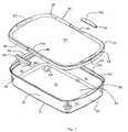
- FIG. 1is a perspective top view of a container and cover in accordance with the present invention showing the cover in a separated condition with the latch handles unassembled;
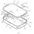
- FIG. 2is a perspective bottom view of the container/cover of FIG. 1 showing the bottom of the cover and container in some detail;
- FIG. 2 ais an enlarged partial cross-sectional view of the cover of FIG. 2 taken along lines 2 a — 2 a showing the disposition of the ribs;
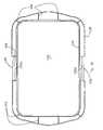
- FIG. 3is a top plan view of the container
- FIG. 4is a cross-sectional view of the container taken along lines 4 — 4 of FIG. 3 showing the angle that the upper portion of the container side wall makes with the vertical;
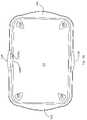
- FIG. 5is a bottom plan view of the cover
- FIG. 6is a side elevational view of the cover
- FIG. 7is a cross-sectional view of the cover taken along lines 7 — 7 of FIG. 5 ;
- FIG. 8is a top plan view of one of the latch handles
- FIG. 9is a bottom plan view of a latch handle
- FIG. 10is a side elevational view of a latch handle
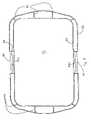
- FIG. 11is a bottom plan view of the container and cover in an assembled and locked position
- FIG. 12is a top perspective view of the container and cover with one of the latch handles rotated to its fully upright position illustrating the simultaneous application of upward pressure to the latch handle and downward pressure to the cover for breaking the seal and releasing the cover from the container;
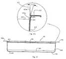
- FIG. 13is a side elevational view of the container and cover in an assembled and locked position
- FIG. 13 ais a enlarged sectional view of the right medial end of the assembled container and cover showing (a) the interference fit between the cover sealing flange and the inside surface of the upper portion of the container side wall and (b) the configuration of the end section of the cover overlying the container handle;
- FIG. 14is a perspective view of another container and cover in accordance with the present invention showing the cover in separated condition with the latch handles unassembled
- FIG. 15is a perspective bottom view of the container/cover of FIG. 14 showing the bottom of the cover and container;
- FIG. 16is a top plan view of the container of FIG. 14 ;
- FIG. 17is a cross-sectional view of the container taken along lines 17 — 17 of FIG. 16 ;
- FIG. 17 aan enlarged sectional view of the right medial end of the container showing the upper portion of the container;
- FIG. 18is a bottom plan view of the cover
- FIG. 19is a side elevational view of the cover
- FIG. 20is a partial cross-sectional view of the cover
- FIG. 21is a top plan view of one of the latch handles
- FIG. 22is a bottom plan view of a latch handle
- FIG. 23is a side elevational view of a latch handle
- FIG. 24is a side elevational view of the container and cover in an assembled and locked position
- FIG. 24 ais an enlarged sectional view of the left medial end of the assembled container and cover showing (a) the sealing fit between the cover sealing fin and the inside surface of the upper portion of the container side wall and (b) the configuration of the end section of the cover overlying the container handle;
- FIG. 25is an enlarged sectional view of the left medial end of the assembled container and cover showing the cover sealing flange and the inside surface of the uppermost portion of the container side wall prior to flexure;
- FIG. 26is an enlarged sectional view of the latch handle in its open position
- FIG. 27is an enlarged sectional view of the latch handle rotated in its closed position
- FIG. 28is a bottom plan view of the container and cover in an assembled and locked position.
- the container 10 of the present inventionincludes a flat bottom wall 12 which merges at its periphery, via a rounded corner 14 , with a peripheral wall, comprising end walls 16 and side walls 18 .
- a peripheral wallcomprising end walls 16 and side walls 18 .
- the container shown in the drawingshas a rectangular shape
- the container of the present inventionmay have a circular or oval shape with only a peripheral upstanding wall.
- the end and side walls of the container 10are merged, via rounded corners 20 , as shown.
- the peripheral wall ( 16 , 18 )terminates in an upper edge 22 , via an outwardly extending convex shaped segment 24 .
- the edge 22surrounds and defines an open top or mouth 25 of the container 10 and forms a pair of horizontally protruding handles 26 above the end walls 16 as shown.
- the top surface of the handlesare substantially level with the plane of the edge 22 simplifying the manufacturing process and allowing the cover to overlie the handles as illustrated for example in FIG. 12 to be described.
- the bottom wall 12 of the containerprojects downwardly at the corners forming triangular shaped protruding feet 28 .
- the peripheral wall ( 16 , 18 )has a slight convex surface, preferably formed along a radius R of about 75 inches, so that an upper section 30 of the peripheral wall (extending below the curved segment 24 ) is disposed at about an angle ⁇ of 2° to 5° and preferably about 3° to the vertical with the bottom 12 lying in a horizontal plane as is illustrated in FIG. 4 .
- This slight anglefacilitates the entry of a peripheral sealing flange or fin 44 on the cover, to enter the mouth of the container and form an interference or sealing fit with an inner sealing surface 30 b formed on a lower portion of the wall section 30 when a cover 32 is seated onto the container, as will be explained in more detail. See FIGS. 4 and 13 a.
- a replaceable cover or lid 32 for use with the container 10is formed with a generally planar depressed wall section 34 which merges with an upwardly inclined peripheral section 36 joined along apex 37 to a downwardly extending outer rim flange or skirt 38 .
- the top of the cover, i.e., wall 34 and section 36forms a dish-like shape for receiving the bottom of a like container/lid combination in a nesting arrangement.
- the outer flange or skirt 38is interrupted by a pair of axel sections 40 which are spaced from the adjacent wall section 34 as is illustrated in FIGS. 1 and 5 to receive latching handles 48 to be described.
- the skirt 38fits over the upper edge of the container except for the axel portions.
- the cover 32includes extended end sections 42 which fit over the top of the container handles 26 in the assembled condition.
- the end sections 42define slightly depressed oblong sections 43 which overlie and accentuate the container handles. See FIG. 13 a.
- the cover 32further includes a downwardly extending inner sealing flange, rib or fin 44 positioned inwardly of the outer skirt 38 .
- the rib or fin 44has a base 44 a joined to the bottom of the wall section 34 and terminates in a free edge 44 b .
- the sealing fin or at least the free edge thereofhas a slightly greater periphery than the periphery of the inside sealing surface 30 b of the peripheral wall of the container so that lower end of the fin 44 is deflected slightly inwardly by the inner sealing surface 30 b of the wall section 30 in the assembled condition. The slight deflection provides an interference and sealing fit between the fin 44 and the inside surface 30 b of the container peripheral wall. See, for example, FIG. 13 a .
- the sealing flange, the outer rim skirt and the inclined peripheral section 36 of the coverform an inverted generally U-shaped cavity.
- Spaced vertical ribs 46are formed along the underside of the peripheral section 36 and extend between the inner sides of the skirt 38 and the base of the sealing flange as shown in FIGS. 2 and 2 a to serve as stop members to limit the downward movement of the cover and thereby control the extent or height of the seal between the cover sealing fin and the container sealing surface.
- the stop memberwhen abutted against the upper edge of the container, informs the user that a positive seal has been obtained.
- the cover sealing flange or rib 44is substantially vertical and the inner sealing surface 30 b on the upper peripheral wall of the container is slanted or canted outwardly by the angle ⁇ of say 2° to 5° degrees.
- the cover sealing flange or ribis canted outwardly in its unstressed or unseated condition and the inner sealing surface of the container wall is generally vertically inclined. With this arrangement as with the embodiment of FIGS. 1–13 , the lower portion of the cover sealing rib is forced inwardly against the container sealing surface to provide the sealing action when the cover is pressed downwardly over the mouth of the container.
- the cover or lid 32is removably secured (and sealed) to the container 10 by means of a pair of oppositely disposed latching handles 48 which engage the underside 50 a of a pair of latch hooks 50 formed on the outside of the peripheral upper edge of the container wall as is illustrated by the dashed lines in FIG. 13 .
- Each latch handleis formed with an upper surface 48 a including an outwardly extending finger engaging surface 48 b , a back wall 48 c and a lower surface.
- the lower surfaceis formed with a pair of short protruding spaced inner walls 48 d which together with the back wall form two semicircular recesses 48 e with downwardly faced openings 48 f for receiving an associated axel 40 .
- the lower latch handle surfacefurther forms a downwardly protruding locking tab 48 g for engaging the lower edge 50 a of an associated locking hook 50 on the container wall. Additionally the lower latch handle surface includes a finger engaging surface 48 h.
- the latch handlesare assembled to the cover or lid 32 by spreading the inner walls 48 slightly away from the back wall 48 c (in a snapping action) to allow each axel to enter the respective recess 48 e .
- the back wall 48 c of each latch handlelimits the rotational movement of the associated latch handle to about 90° by engaging the edge 34 a of the wall 34 when the upper surface of the handle is about parallel to the surface 34 .
- the edge 34 amay include a small upward curvature formed as part of the arched peripheral section 36 .
- skirt 38while fitting over the upper edge of the container, except for the axel portions, does not extend under the upper peripheral edge of the container wall. As a result, only the latch handles serve to lock the cover and container together.
- the cover 32 with the latch handles assembled thereonmay be placed over the mouth or top 24 of the container 10 and then pressed downwardly until the ribs 46 are seated on the container's upper edge 22 .
- the inner sealing flange 44forms an interference fit with the inside of the container peripheral wall.
- the latch handlesmay then be easily rotated to a closed position by pressing downwardly and inwardly on the finger engaging surfaces 48 b until the locking tabs 48 g snap under the locking hooks 50 .
- latch handle(or both) may be rotated to its upper most position and pressed upwardly (e.g., by a finger 52 ) while an area of the planar surface 34 of the cover adjacent the handle is simultaneously pressed downwardly (e.g., by a thumb 54 ). This simple maneuver causes the surface 34 to assume a slightly concave bow to break the seal and release the cover from the container. See FIG. 12 .
- FIGS. 14–17Another preferred embodiment of a storage container and lid is illustrated in FIGS. 14–17 .
- This embodimentis very similar to the embodiment of FIGS. 1–13 except that the sealing rib on the lid is canted outwardly and the inner sealing surface along the upper portion of the container peripheral wall is about vertical.
- the container 110like the container 10 , includes a flat bottom wall 112 which merges at its periphery, through rounded corners 114 , with a peripheral wall, comprising end walls 116 and side walls 118 . The end and side walls of the container 110 are merged through rounded corners 120 .
- the peripheral wall ( 116 , 118 )terminates in an upper edge 122 .
- the edge 122surrounds and defines an open top or mouth 125 of the container 110 and forms a pair of horizontally protruding handles 126 above the end walls 116 as shown.
- the top surface of the handlesare substantially level with the plane of the edge 122 simplifying the manufacturing process and allowing the cover to overlie the handles.
- the bottom wall 112 of the containerprojects downwardly at the corners forming triangular shaped protruding feet 128 .
- the uppermost section of peripheral wall( 116 , 118 ) has a short transition or lead in wall segment 123 extending below the upper edge 122 and above a surface 124 a formed on the inside of an upper section 124 of the peripheral wall as is best illustrated in FIGS. 17 a , 24 a , 25 and 27 .
- the surface 124 awhich circumscribes the interior of the upper peripheral wall is referred to as the inside sealing surface.
- the short lead in segment 123is inclined outwardly at an angle ⁇ to the vertical. The angle ⁇ and angle ⁇ (to be discussed) between the cover sealing rib or fin and the vertical must be correlated to allow the lid to be seated on the container with a reasonable amount of force.
- the angled lead in segment 123 and the inner surface 123 a formedthereby facilitate the entry of an inner sealing rib or fin 144 (described below) on the cover to enter the mouth of the container and form a sealing fit with the generally rectangular sealing surface area 124 a when a cover 132 is seated onto the container.
- This angled transition wall segment 123also facilitates removal of the cover. See FIGS. 24 and 25 .
- the transition wall segmentmay be about 1/16 to 1 ⁇ 8 inches in height.
- the angle ⁇should not exceed 45° and preferably is within the range of about 10° to 20° and most preferably about 15°.
- the inside sealing surface 124 a of wall section 124is generally vertically disposed. Reference numbers 127 and 129 ( FIG.
- 17 aindicate the direction of vertical planes and horizontal planes, respectively, in relation to the container bottom 122 .
- the rest of wall 118 below the wall section 124may taper inwardly to the bottom 112 , which facilitates nesting of two or more containers.
- a replaceable cover or lid 132 for use with the container 110is formed with a generally planar depressed wall section 134 which merges with an upwardly inclined peripheral section 136 joined along apex 137 to a downwardly extending outer rim flange or skirt 138 .
- the top of the cover, i.e., wall 134 and section 136forms a dish-like shape for receiving the bottom of a like container/lid combination in a nesting arrangement.
- the outer flange or skirt 138is interrupted by a pair of axel sections 140 which are spaced from the adjacent wall section 134 a as is illustrated in FIGS. 14 and 18 to receive latching handles 148 to be described.
- the skirt 138fits over the upper edge of the container except for the axel portions and like the skirt 38 of the cover 32 , does not extend under the upper peripheral edge of the container wall.
- the cover 132includes extended end sections 142 which fit over the top of the container handles 126 in the assembled condition.
- the end sections 142define slightly depressed oblong sections 143 that overlie and accentuate the container handles. See FIG. 14 .
- the cover 132further includes a downwardly extending inner sealing flange, rib or fin 144 positioned inwardly of the outer skirt 138 .
- the flange or fin 144is canted or inclined outwardly from the vertical through an angle ⁇ such that the free end 144 a of the fin 144 is deflected or bent inwardly by the container inside sealing surface 124 a with the lower half portion 144 b of the fin being seated against the sealing surface 124 a in the assembled condition.
- the cant or inclination angle ⁇( FIG. 26 ) may be as great as 20° but preferably is in the range of about 4° to 8° and most preferably about 6°.
- the deflection of the fin 144 by the inside sealing surface 124 a of the wall section 124provides a bending force and consequentially a lateral force there-between which enhances a sealing or interference fit between the fin 144 and the inside surface 124 a of the container wall section 124 .
- the free edge 144 a of the sealing fin 144has a greater periphery than the periphery of the container inside sealing surface 124 a . See, for example, FIG. 24 a.
- a length to height ratio for the fin 144is preferably about 4.0 to 5.0 and most preferably about 4.5 for ease of manufacturing the rib integrally with the cover by injection molding processes.
- a fin with a thickness of 0.055 inches at its base 144 cwould most preferably be 0.25 inches in height.
- the fin or rib 144has a draft, i.e., thinner at the free end than at the base, of about 2° to 3°. The lower this height to width ratio the easier and more reliable the manufacturing process.
- the selection of the fin cant angle ⁇ , the height of the fin and placement of the fin on the cover in relation to the vertical sealing wall section 124 when the cover and container are matedare preferably selected such that about one-half of the fin's lower surface area is pressed into contact with the inner sealing surface 124 a .
- the amount of flexure, i.e., bending of the sealing fin 144preferably should not exceed 20% to 30% of the maximum yield strength of the fin.
- the vertical force required to seat the lid on the containermay be of the order of 6 to 10 and preferably about 8 ounces per linear inch to accommodate the strength of the anticipated users while providing the desired seal.
- Spaced vertical ribs 146are formed along the underside of the peripheral section 136 and the inner side of skirt 138 as shown in FIGS. 15 and 18 to provide structural rigidity and seat on the upper edge 122 of the container.
- a pair of oppositely disposed latch handles 148engage the underside 150 a of a pair of latch hooks 150 formed on the peripheral upper edge of the container wall.
- Each latch handleis formed with an upper surface 148 a including an outwardly extending finger engaging surface 148 b , a back wall 148 c and a lower surface.
- the lower surfaceis formed with a pair of short protruding spaced inner walls 148 d which together with the back wall form two semicircular recesses 148 e with downwardly faced openings 148 f for receiving an associated axel 140 .
- the lower latch handle surfacefurther forms a downwardly protruding locking tab 148 g with a bead 148 i for engaging the lower edge 150 a of an associated locking hook 150 on the container wall.
- the lower latch handle surfaceincludes a finger engaging surface 148 h.
- the latch handles 148are snapped onto the axels 140 and the cover 132 placed over the mouth or top 125 of the container 110 with the fin inserted into the transition segment facilitating the assembly process. See FIGS. 24 and 25 .
- the cover 132is then pressed downwardly until the ribs 146 are seated on the container's upper edge 122 . In this position the sealing fin 144 forms a seal with the inside of the container. See FIGS. 23 a and 26 .
- the latch handles 148may then be easily rotated to a closed position by pressing downwardly and inwardly on the finger engaging surfaces 148 b until the locking tabs 148 g is rotated to snap the bead 148 i under the locking hooks 150 as illustrated in FIG. 26 .
- Removal of the cover from the containermay be accomplished similarly to the first above-described embodiment as described and illustrated with reference to FIG. 12 .
- the container ( 10 , 110 )may be made (i.e., injection molded) of a suitable rigid or semi-rigid plastic such as polypropylene, but is preferably made of polycarbonate which is suitable for microwave and conventional dishwasher use. While the bottom of the container may be frosted the sides are preferably transparent or translucent to enable the food or material stored in the container to be readily viewed. It should be noted that to vent excess gas pressure from the container interior (as a result of cooking) it is only necessary to unlatch one of the latch handles.
- the cover or lid ( 32 , 132 ) as well as the latch handlesmay also be made of a suitable plastic, but are preferably made of polypropylene, having sufficient rigidity so that the inner flange of skirt ( 44 , 144 ) forms an interference or sealing fit with the inner surface of the container wall in the assembled condition.
- the coveralso preferably has sufficient beam strength and flexibility so that when an upward force is exerted on the finger engaging lower surface ( 48 h , 148 h of one or both latch handles (when in their upward most position) and a downward force is exerted on the planar top cover surface adjacent the latch handle the outer rim flange ( 38 , 138 ) will flex outwardly and upwardly to break the seal and disengage the cover from the container. This feature adds to the user friendliness of the container/lid arrangement and particularly for persons suffering from arthritis or tendinitis of the hands an wrists.
- the above-described storage container/cover arrangementscan be made in a variety of sizes, i.e., lengths, widths and depths (e.g., 12′′ ⁇ 71 ⁇ 2′′ ⁇ 2′′ etc.), with or without a designed stacking system.
- the container with the cover removedmay be used as a serving dish.
Landscapes
- Engineering & Computer Science (AREA)
- Mechanical Engineering (AREA)
- Closures For Containers (AREA)
Abstract
Description
Claims (29)
Priority Applications (1)
| Application Number | Priority Date | Filing Date | Title |
|---|---|---|---|
| US10/717,044US7090089B2 (en) | 2001-01-25 | 2003-11-19 | Container and sealing cover |
Applications Claiming Priority (5)
| Application Number | Priority Date | Filing Date | Title |
|---|---|---|---|
| WOPCT/US01/02434 | 2001-01-25 | ||
| PCT/US2001/002434WO2002059005A1 (en) | 2001-01-25 | 2001-01-25 | Container and sealing cover with latch handles |
| US10/204,684US20030015534A1 (en) | 2001-01-25 | 2001-07-10 | Container and sealing cover |
| PCT/US2001/041317WO2002059007A1 (en) | 2001-01-25 | 2001-07-10 | Container and sealing cover |
| US10/717,044US7090089B2 (en) | 2001-01-25 | 2003-11-19 | Container and sealing cover |
Related Parent Applications (3)
| Application Number | Title | Priority Date | Filing Date |
|---|---|---|---|
| PCT/US2001/041317ContinuationWO2002059007A1 (en) | 2001-01-25 | 2001-07-10 | Container and sealing cover |
| US10204684Continuation | 2001-07-10 | ||
| US10/204,684ContinuationUS20030015534A1 (en) | 2001-01-25 | 2001-07-10 | Container and sealing cover |
Publications (2)
| Publication Number | Publication Date |
|---|---|
| US20040099669A1 US20040099669A1 (en) | 2004-05-27 |
| US7090089B2true US7090089B2 (en) | 2006-08-15 |
Family
ID=22758994
Family Applications (2)
| Application Number | Title | Priority Date | Filing Date |
|---|---|---|---|
| US10/204,684AbandonedUS20030015534A1 (en) | 2001-01-25 | 2001-07-10 | Container and sealing cover |
| US10/717,044Expired - Fee RelatedUS7090089B2 (en) | 2001-01-25 | 2003-11-19 | Container and sealing cover |
Family Applications Before (1)
| Application Number | Title | Priority Date | Filing Date |
|---|---|---|---|
| US10/204,684AbandonedUS20030015534A1 (en) | 2001-01-25 | 2001-07-10 | Container and sealing cover |
Country Status (1)
| Country | Link |
|---|---|
| US (2) | US20030015534A1 (en) |
Cited By (73)
| Publication number | Priority date | Publication date | Assignee | Title |
|---|---|---|---|---|
| US20060048336A1 (en)* | 2004-09-08 | 2006-03-09 | Joerg-Uwe Dahl | Hinge construction and protective device having a hinge construction |
| US20060249522A1 (en)* | 2005-05-06 | 2006-11-09 | Dobbs-Stanford Corporation | Reusable container for retail display of electric cable components |
| US20080105684A1 (en)* | 2004-12-14 | 2008-05-08 | Brendan John Lindsay | Latchable Lid Assemblies |
| US20090008284A1 (en)* | 2006-02-16 | 2009-01-08 | Snapware Corporation | Container/Lid Combination For Storing Food and other Articles |
| US20090078715A1 (en)* | 2007-09-21 | 2009-03-26 | Daewoo Tech, Co., Ltd | Lid for airtight container |
| US20090218360A1 (en)* | 2008-02-29 | 2009-09-03 | Suk Jong Cheul | Lid for Airtight Containers |
| US20090218351A1 (en)* | 2008-03-03 | 2009-09-03 | Antal Sr Keith E | Resealing overcap for a container |
| US20100024663A1 (en)* | 2007-03-16 | 2010-02-04 | Tsann Kuen (China) Enterprise Co., Ltd. | Handle for a grill pan |
| US20100072100A1 (en)* | 2008-09-18 | 2010-03-25 | Wilton Industries, Inc. | Dry ingredients container |
| USD617150S1 (en) | 2009-10-07 | 2010-06-08 | Dart Industries Inc. | Container for food |
| USD617151S1 (en) | 2009-10-07 | 2010-06-08 | Dart Industries Inc. | Container for food |
| USD617149S1 (en) | 2009-10-07 | 2010-06-08 | Dart Industries Inc. | Container for food |
| US20100140285A1 (en)* | 2008-12-04 | 2010-06-10 | Sam Kwang Glass Ind. Co., Ltd. | Airtight container and mold for press-forming the airtight container |
| US20110036842A1 (en)* | 2009-08-17 | 2011-02-17 | Robert Sellari | Tamper evident containers |
| USD651475S1 (en) | 2010-06-25 | 2012-01-03 | Sistema Plastics Limited | Food container assembly |
| USD652265S1 (en) | 2010-07-30 | 2012-01-17 | Sistema Plastics Limited | Component parts of a container assembly |
| USD652686S1 (en) | 2010-07-30 | 2012-01-24 | Sistema Plastics Limited | Container assembly |
| USD666879S1 (en)* | 2010-06-24 | 2012-09-11 | Sussex Im, Inc. | Container having multiple storage compartments |
| KR101215439B1 (en) | 2012-06-29 | 2012-12-26 | 주식회사 혜성 | Airtight container with detachable locking member |
| USD673808S1 (en) | 2012-03-10 | 2013-01-08 | Wki Holding Company, Inc. | Container lid |
| USD673807S1 (en) | 2012-03-10 | 2013-01-08 | Wki Holding Company, Inc. | Container lid |
| USD675057S1 (en) | 2012-03-09 | 2013-01-29 | Wki Holding Company, Inc. | Lid |
| US8376181B2 (en) | 2010-05-21 | 2013-02-19 | Wki Holding Company, Inc. | Container assembly with flexible lid seal and releasing arrangement |
| US8387822B2 (en) | 2010-07-08 | 2013-03-05 | Sonoco Development, Inc. | Sealing lid for a container |
| USD677521S1 (en) | 2011-02-22 | 2013-03-12 | Sistema Plastics Limited | Container lid |
| USD682609S1 (en) | 2010-07-30 | 2013-05-21 | Sistema Plastics Limited | Lid assembly with utensils |
| KR101300698B1 (en)* | 2012-05-15 | 2013-08-26 | 주식회사 혜성 | Air tight container with detachable locking member |
| US8534492B2 (en) | 2011-04-01 | 2013-09-17 | Wki Holding Company, Inc. | Container with air-tight lid |
| KR200469104Y1 (en)* | 2011-12-02 | 2013-09-25 | 김진란 | A shut container |
| US20130306636A1 (en)* | 2011-01-28 | 2013-11-21 | Emsa Gmbh | Storage container set |
| US8678230B2 (en) | 2010-07-30 | 2014-03-25 | Snapware Corporation | Vessels with air-tight lid systems |
| USD703912S1 (en)* | 2013-03-15 | 2014-04-29 | Paw Pods, LLC | Pet burial pod |
| USD704503S1 (en) | 2012-06-19 | 2014-05-13 | Sistema Plastics Limited | Lid for a container |
| US8733550B2 (en) | 2012-03-09 | 2014-05-27 | Wki Holding Company, Inc. | Nesting container lids with snap on wings |
| USD706084S1 (en) | 2012-06-19 | 2014-06-03 | Sistema Plastics Limited | Lidded container |
| US8746487B1 (en)* | 2013-03-05 | 2014-06-10 | Lifefactory, Inc. | Food container |
| USD707082S1 (en) | 2013-02-06 | 2014-06-17 | Camelbak Products, Llc | Pitcher lid |
| USD708888S1 (en) | 2013-02-06 | 2014-07-15 | Camelbak Products, Llc | Pitcher |
| USD708887S1 (en) | 2013-02-06 | 2014-07-15 | Camelbak Products, Llc | Pitcher body |
| USD709592S1 (en) | 2013-02-07 | 2014-07-22 | Camelbak Products, Llc | Filter housing for a water filtration pitcher |
| US20150068550A1 (en)* | 2013-09-09 | 2015-03-12 | Tokiwa Corporation | Cosmetic container |
| US9038843B2 (en) | 2013-03-05 | 2015-05-26 | Lifefactory, Inc. | Food container |
| USD734980S1 (en)* | 2013-09-06 | 2015-07-28 | Kraft Foods Group Brands Llc | Lid for a container |
| USD743742S1 (en) | 2012-01-02 | 2015-11-24 | Brita Gmbh | Drinking bottle |
| US9340330B2 (en) | 2010-06-24 | 2016-05-17 | S. C. Johnson & Son, Inc. | Storage container lids |
| US9820616B2 (en) | 2015-03-06 | 2017-11-21 | Wki Holding Company, Inc. | Securable food storage container assembly |
| US20180237185A1 (en)* | 2017-02-17 | 2018-08-23 | Barenthal North America, Inc. | Storage tote with latching handle |
| USD830765S1 (en) | 2016-03-04 | 2018-10-16 | Rubbermaid Incorporated | Lid for container |
| USD833211S1 (en) | 2016-03-04 | 2018-11-13 | Rubbermaid Incorporated | Lid for container |
| US10173826B2 (en) | 2015-05-15 | 2019-01-08 | Rubbermaid Incorporated | Ventable storage container and method of use |
| USD837588S1 (en) | 2016-03-04 | 2019-01-08 | Rubbermaid Incorporated | Lid for container |
| US20190335946A1 (en)* | 2018-05-02 | 2019-11-07 | Dart Industries Inc. | Microwave reheating container |
| USD878876S1 (en)* | 2018-05-24 | 2020-03-24 | Sun Coast Merchandise Corp. | Bento box food container |
| USD897199S1 (en)* | 2018-08-17 | 2020-09-29 | The Decor Corporation Pty. Ltd. | Container part |
| USD898360S1 (en) | 2018-05-11 | 2020-10-13 | Sto Responsible, LLC | Childproof storage container |
| USD906767S1 (en) | 2020-07-29 | 2021-01-05 | E. Mishan & Sons, Inc. | Food storage container |
| USD911119S1 (en)* | 2019-10-15 | 2021-02-23 | Jing Zhong | Lunch box |
| USD921445S1 (en)* | 2018-11-30 | 2021-06-08 | Sistema Plastics Limited | Container |
| USD921444S1 (en)* | 2018-11-30 | 2021-06-08 | Sistema Plastics Limited | Container |
| TWI730914B (en)* | 2020-10-15 | 2021-06-11 | 啟碁科技股份有限公司 | Waterproof device |
| US20210284398A1 (en)* | 2020-03-16 | 2021-09-16 | Helen Of Troy Limited | Container with venting or multiple sealing feature |
| USD941523S1 (en) | 2018-08-22 | 2022-01-18 | Sto Responsible, LLC | Child-resistant storage container |
| US11319135B2 (en)* | 2017-09-29 | 2022-05-03 | Packit, Llc | Food storage container |
| USD962020S1 (en)* | 2022-05-31 | 2022-08-30 | Taoyue Zhang | Lunch box |
| USD963436S1 (en)* | 2021-12-15 | 2022-09-13 | Haixia Chen | Lunch box |
| USD966830S1 (en)* | 2020-01-30 | 2022-10-18 | Sistema Plastics Limited | Lidded container |
| US11471003B1 (en) | 2021-12-30 | 2022-10-18 | Matthew Wade Perkins | Combination cutting board and sealable container |
| USD971701S1 (en)* | 2021-08-19 | 2022-12-06 | Zhengzhou Chenglan E-commerce Co., Ltd. | Lunch box |
| US20230061938A1 (en)* | 2021-08-30 | 2023-03-02 | Techtronic Cordless Gp | Accessory case |
| USD1015081S1 (en)* | 2021-12-02 | 2024-02-20 | Dongguan Oumeng Houseware Products Co., Ltd | Lunch box |
| USD1032308S1 (en)* | 2022-03-03 | 2024-06-25 | Yiyu Zhang | Electric lunch box |
| USD1051679S1 (en)* | 2021-12-27 | 2024-11-19 | Deers Holdings Inc. | Lunch box |
| USD1064766S1 (en)* | 2023-03-10 | 2025-03-04 | Ceres Chill Co. | Tray for forming portioned frozen products |
Families Citing this family (26)
| Publication number | Priority date | Publication date | Assignee | Title |
|---|---|---|---|---|
| US6827224B2 (en)* | 2002-04-16 | 2004-12-07 | A Better Way, Inc. | Food liquid strainer for cooking |
| US7124891B2 (en)* | 2003-10-28 | 2006-10-24 | Foldware, Inc. | Nestable containers with reversibly deformable closures |
| US20060254948A1 (en)* | 2005-05-05 | 2006-11-16 | Herbert Curtis B | Nestable containers with folding coverings |
| US20070062831A1 (en)* | 2005-09-21 | 2007-03-22 | Chang-Ying Chen | Safety switch of a toolbox |
| US20070131701A1 (en)* | 2005-12-01 | 2007-06-14 | Herbert Curtis B | Nestable containers with bending covers for improved storage |
| USD556517S1 (en) | 2006-02-17 | 2007-12-04 | Snapware Corporation | Combined airtight lid and container |
| USD562083S1 (en) | 2006-02-17 | 2008-02-19 | Snapware Corporation | Combined airtight lid and container |
| WO2007121746A2 (en)* | 2006-04-22 | 2007-11-01 | Tanos Gmbh | A storage device comprising two parts |
| JP4809714B2 (en)* | 2006-05-12 | 2011-11-09 | ミライアル株式会社 | Thin plate storage container |
| KR101083880B1 (en)* | 2007-10-30 | 2011-11-15 | 문기원 | Areceptacle for food with locking |
| CA2686644A1 (en)* | 2008-11-28 | 2010-05-28 | Green Ripple Innovations Inc. | Cleaning supplies caddy |
| DE102010016507A1 (en)* | 2010-04-19 | 2011-10-20 | Rittal Gmbh & Co. Kg | Air guide arrangement |
| US8703312B2 (en)* | 2011-12-23 | 2014-04-22 | Samsung Sdi Co., Ltd. | Battery module |
| US9551695B2 (en)* | 2012-01-24 | 2017-01-24 | Lindon Group, Inc. | Personal substance detection field test kit |
| US8771770B1 (en)* | 2013-01-17 | 2014-07-08 | Multisorb Technologies, Inc. | Long life dough package |
| CN104302028B (en)* | 2013-07-17 | 2017-06-16 | 广东美的厨房电器制造有限公司 | High-frequency heating apparatus and its power control method and power control |
| JP6402065B2 (en)* | 2015-04-01 | 2018-10-10 | 三甲株式会社 | Container with lid |
| CN106275796B (en)* | 2015-05-13 | 2019-06-04 | 奔迈(上海)国际贸易有限公司 | A kind of storage box and its box body, box cover and lock |
| WO2017155835A1 (en)* | 2016-03-05 | 2017-09-14 | Wki Holding Company, Inc. | Cookware assembly with a securable lid for bakeware |
| US10974874B2 (en)* | 2018-11-01 | 2021-04-13 | Oneida Consumer, Llc | Lid assembly for a container |
| CN113451960B (en)* | 2020-03-27 | 2025-08-05 | 深圳市大富科技股份有限公司 | Base station and its junction box |
| US11738914B2 (en) | 2021-11-18 | 2023-08-29 | Yeti Coolers, Llc | Container and latching system |
| US11738935B1 (en)* | 2022-04-22 | 2023-08-29 | Tate Koenig | Expandable pizza container |
| US11661260B1 (en)* | 2022-04-22 | 2023-05-30 | Tate Koenig | Expandable pizza container |
| TWI829308B (en)* | 2022-08-26 | 2024-01-11 | 詠業科技股份有限公司 | Strip-shaped hook structure and containing box thereof |
| KR20250015153A (en)* | 2023-07-24 | 2025-02-03 | (주)네오플램 | Airtight Container |
Citations (8)
| Publication number | Priority date | Publication date | Assignee | Title |
|---|---|---|---|---|
| US4765506A (en)* | 1987-05-12 | 1988-08-23 | Apl Corporation | Combination storage container and triple seal lid |
| US5383565A (en)* | 1990-08-08 | 1995-01-24 | Portola Packaging, Inc. | Neck finish for containers of rigid material |
| US5520301A (en)* | 1992-12-01 | 1996-05-28 | Berner Kunststofftechnik Gmbh | Plastic packaging |
| US5531345A (en)* | 1993-10-12 | 1996-07-02 | Sumitomo Wiring Systems, Ltd. | Fitting construction of electrical connection box |
| US5641065A (en)* | 1995-06-22 | 1997-06-24 | Paragon Group Of Plastics Companies, Inc. | Medical instrument soaking, transporting and storage container |
| US6269967B1 (en)* | 1995-05-23 | 2001-08-07 | Wavin Trepak, B.V. | Rectangular container with cover |
| US6279774B1 (en)* | 1996-08-30 | 2001-08-28 | Southcorp Packaging Usa | Cover locking mechanism |
| US6793096B1 (en)* | 2003-04-08 | 2004-09-21 | Hana Cobi Co., Ltd. | Food item receiving container |
- 2001
- 2001-07-10USUS10/204,684patent/US20030015534A1/ennot_activeAbandoned
- 2003
- 2003-11-19USUS10/717,044patent/US7090089B2/ennot_activeExpired - Fee Related
Patent Citations (8)
| Publication number | Priority date | Publication date | Assignee | Title |
|---|---|---|---|---|
| US4765506A (en)* | 1987-05-12 | 1988-08-23 | Apl Corporation | Combination storage container and triple seal lid |
| US5383565A (en)* | 1990-08-08 | 1995-01-24 | Portola Packaging, Inc. | Neck finish for containers of rigid material |
| US5520301A (en)* | 1992-12-01 | 1996-05-28 | Berner Kunststofftechnik Gmbh | Plastic packaging |
| US5531345A (en)* | 1993-10-12 | 1996-07-02 | Sumitomo Wiring Systems, Ltd. | Fitting construction of electrical connection box |
| US6269967B1 (en)* | 1995-05-23 | 2001-08-07 | Wavin Trepak, B.V. | Rectangular container with cover |
| US5641065A (en)* | 1995-06-22 | 1997-06-24 | Paragon Group Of Plastics Companies, Inc. | Medical instrument soaking, transporting and storage container |
| US6279774B1 (en)* | 1996-08-30 | 2001-08-28 | Southcorp Packaging Usa | Cover locking mechanism |
| US6793096B1 (en)* | 2003-04-08 | 2004-09-21 | Hana Cobi Co., Ltd. | Food item receiving container |
Cited By (97)
| Publication number | Priority date | Publication date | Assignee | Title |
|---|---|---|---|---|
| US20060048336A1 (en)* | 2004-09-08 | 2006-03-09 | Joerg-Uwe Dahl | Hinge construction and protective device having a hinge construction |
| US7574773B2 (en)* | 2004-09-08 | 2009-08-18 | Siemens Aktiengesellschaft | Hinge construction and protective device having a hinge construction |
| US20080105684A1 (en)* | 2004-12-14 | 2008-05-08 | Brendan John Lindsay | Latchable Lid Assemblies |
| US8596485B2 (en)* | 2004-12-14 | 2013-12-03 | Sistema Plastics Limited | Latchable lid assemblies |
| US20060249522A1 (en)* | 2005-05-06 | 2006-11-09 | Dobbs-Stanford Corporation | Reusable container for retail display of electric cable components |
| US20090008284A1 (en)* | 2006-02-16 | 2009-01-08 | Snapware Corporation | Container/Lid Combination For Storing Food and other Articles |
| US8596492B2 (en)* | 2006-02-16 | 2013-12-03 | Snapware Corporation | System for aiding the visual matching of containers having diverse openings with corresponding lids |
| US20100024663A1 (en)* | 2007-03-16 | 2010-02-04 | Tsann Kuen (China) Enterprise Co., Ltd. | Handle for a grill pan |
| US20090078715A1 (en)* | 2007-09-21 | 2009-03-26 | Daewoo Tech, Co., Ltd | Lid for airtight container |
| US20090218360A1 (en)* | 2008-02-29 | 2009-09-03 | Suk Jong Cheul | Lid for Airtight Containers |
| US7854344B2 (en)* | 2008-02-29 | 2010-12-21 | Suk Jong Cheul | Lid having locking flap handles with improved elastic hinges for airtight containers |
| US20090218351A1 (en)* | 2008-03-03 | 2009-09-03 | Antal Sr Keith E | Resealing overcap for a container |
| US7909204B2 (en) | 2008-03-03 | 2011-03-22 | Sonoco Development, Inc. | Resealing overcap for a container |
| US20100072100A1 (en)* | 2008-09-18 | 2010-03-25 | Wilton Industries, Inc. | Dry ingredients container |
| US7997412B2 (en) | 2008-09-18 | 2011-08-16 | Wilton Industries Inc. | Dry ingredients container |
| US20100140285A1 (en)* | 2008-12-04 | 2010-06-10 | Sam Kwang Glass Ind. Co., Ltd. | Airtight container and mold for press-forming the airtight container |
| US8371468B2 (en) | 2009-08-17 | 2013-02-12 | Inline Plastics Corp. | Tamper evident containers |
| US20110036842A1 (en)* | 2009-08-17 | 2011-02-17 | Robert Sellari | Tamper evident containers |
| USD617149S1 (en) | 2009-10-07 | 2010-06-08 | Dart Industries Inc. | Container for food |
| USD617151S1 (en) | 2009-10-07 | 2010-06-08 | Dart Industries Inc. | Container for food |
| USD617150S1 (en) | 2009-10-07 | 2010-06-08 | Dart Industries Inc. | Container for food |
| US8376181B2 (en) | 2010-05-21 | 2013-02-19 | Wki Holding Company, Inc. | Container assembly with flexible lid seal and releasing arrangement |
| USD666879S1 (en)* | 2010-06-24 | 2012-09-11 | Sussex Im, Inc. | Container having multiple storage compartments |
| USD668119S1 (en)* | 2010-06-24 | 2012-10-02 | Sussex Im, Inc. | Container with internal compartment |
| US9340330B2 (en) | 2010-06-24 | 2016-05-17 | S. C. Johnson & Son, Inc. | Storage container lids |
| USD651475S1 (en) | 2010-06-25 | 2012-01-03 | Sistema Plastics Limited | Food container assembly |
| US8387822B2 (en) | 2010-07-08 | 2013-03-05 | Sonoco Development, Inc. | Sealing lid for a container |
| USD652686S1 (en) | 2010-07-30 | 2012-01-24 | Sistema Plastics Limited | Container assembly |
| US8678230B2 (en) | 2010-07-30 | 2014-03-25 | Snapware Corporation | Vessels with air-tight lid systems |
| USD662424S1 (en) | 2010-07-30 | 2012-06-26 | Sistema Plastics Limited | Component part of a container assembly |
| USD682609S1 (en) | 2010-07-30 | 2013-05-21 | Sistema Plastics Limited | Lid assembly with utensils |
| USD652265S1 (en) | 2010-07-30 | 2012-01-17 | Sistema Plastics Limited | Component parts of a container assembly |
| US20130306636A1 (en)* | 2011-01-28 | 2013-11-21 | Emsa Gmbh | Storage container set |
| US8714394B2 (en)* | 2011-01-28 | 2014-05-06 | Emsa Gmbh | Storage container having locking lid |
| USD677521S1 (en) | 2011-02-22 | 2013-03-12 | Sistema Plastics Limited | Container lid |
| US8534492B2 (en) | 2011-04-01 | 2013-09-17 | Wki Holding Company, Inc. | Container with air-tight lid |
| KR200469104Y1 (en)* | 2011-12-02 | 2013-09-25 | 김진란 | A shut container |
| USD743742S1 (en) | 2012-01-02 | 2015-11-24 | Brita Gmbh | Drinking bottle |
| USD744781S1 (en) | 2012-01-02 | 2015-12-08 | Brita Gmbh | Drinking bottle |
| USD675057S1 (en) | 2012-03-09 | 2013-01-29 | Wki Holding Company, Inc. | Lid |
| US9663276B2 (en) | 2012-03-09 | 2017-05-30 | Wki Holding Company, Inc. | Compressible seal member for container |
| US8733550B2 (en) | 2012-03-09 | 2014-05-27 | Wki Holding Company, Inc. | Nesting container lids with snap on wings |
| US9187223B2 (en) | 2012-03-09 | 2015-11-17 | Wki Holding Company, Inc. | Nesting container lids with snap on wings |
| USD673807S1 (en) | 2012-03-10 | 2013-01-08 | Wki Holding Company, Inc. | Container lid |
| USD673808S1 (en) | 2012-03-10 | 2013-01-08 | Wki Holding Company, Inc. | Container lid |
| KR101300698B1 (en)* | 2012-05-15 | 2013-08-26 | 주식회사 혜성 | Air tight container with detachable locking member |
| USD706084S1 (en) | 2012-06-19 | 2014-06-03 | Sistema Plastics Limited | Lidded container |
| USD704503S1 (en) | 2012-06-19 | 2014-05-13 | Sistema Plastics Limited | Lid for a container |
| KR101215439B1 (en) | 2012-06-29 | 2012-12-26 | 주식회사 혜성 | Airtight container with detachable locking member |
| USD708887S1 (en) | 2013-02-06 | 2014-07-15 | Camelbak Products, Llc | Pitcher body |
| USD707082S1 (en) | 2013-02-06 | 2014-06-17 | Camelbak Products, Llc | Pitcher lid |
| USD708888S1 (en) | 2013-02-06 | 2014-07-15 | Camelbak Products, Llc | Pitcher |
| USD709592S1 (en) | 2013-02-07 | 2014-07-22 | Camelbak Products, Llc | Filter housing for a water filtration pitcher |
| US8746487B1 (en)* | 2013-03-05 | 2014-06-10 | Lifefactory, Inc. | Food container |
| US9376232B2 (en)* | 2013-03-05 | 2016-06-28 | Lifefactory, Inc. | Food container |
| US20150239606A1 (en)* | 2013-03-05 | 2015-08-27 | Lifefactory, Inc. | Food container |
| US9067713B2 (en)* | 2013-03-05 | 2015-06-30 | Lifefactory, Inc. | Food container |
| US9038843B2 (en) | 2013-03-05 | 2015-05-26 | Lifefactory, Inc. | Food container |
| US20140252000A1 (en)* | 2013-03-05 | 2014-09-11 | Lifefactory, Inc. | Food Container |
| USD703912S1 (en)* | 2013-03-15 | 2014-04-29 | Paw Pods, LLC | Pet burial pod |
| USD734980S1 (en)* | 2013-09-06 | 2015-07-28 | Kraft Foods Group Brands Llc | Lid for a container |
| US20150068550A1 (en)* | 2013-09-09 | 2015-03-12 | Tokiwa Corporation | Cosmetic container |
| US9237792B2 (en)* | 2013-09-09 | 2016-01-19 | Tokiwa Corporation | Cosmetic container |
| US9820616B2 (en) | 2015-03-06 | 2017-11-21 | Wki Holding Company, Inc. | Securable food storage container assembly |
| US10173826B2 (en) | 2015-05-15 | 2019-01-08 | Rubbermaid Incorporated | Ventable storage container and method of use |
| USD830765S1 (en) | 2016-03-04 | 2018-10-16 | Rubbermaid Incorporated | Lid for container |
| USD833211S1 (en) | 2016-03-04 | 2018-11-13 | Rubbermaid Incorporated | Lid for container |
| USD837588S1 (en) | 2016-03-04 | 2019-01-08 | Rubbermaid Incorporated | Lid for container |
| US20180237185A1 (en)* | 2017-02-17 | 2018-08-23 | Barenthal North America, Inc. | Storage tote with latching handle |
| US10450104B2 (en)* | 2017-02-17 | 2019-10-22 | Barenthal North America, Inc. | Storage tote with latching handle |
| US11319135B2 (en)* | 2017-09-29 | 2022-05-03 | Packit, Llc | Food storage container |
| US11160415B2 (en)* | 2018-05-02 | 2021-11-02 | Dart Industries Inc. | Microwave reheating container |
| US20190335946A1 (en)* | 2018-05-02 | 2019-11-07 | Dart Industries Inc. | Microwave reheating container |
| USD898360S1 (en) | 2018-05-11 | 2020-10-13 | Sto Responsible, LLC | Childproof storage container |
| US11136173B2 (en) | 2018-05-11 | 2021-10-05 | Sto Responsible, LLC | Child-resistant storage container |
| USD878876S1 (en)* | 2018-05-24 | 2020-03-24 | Sun Coast Merchandise Corp. | Bento box food container |
| USD897199S1 (en)* | 2018-08-17 | 2020-09-29 | The Decor Corporation Pty. Ltd. | Container part |
| USD941523S1 (en) | 2018-08-22 | 2022-01-18 | Sto Responsible, LLC | Child-resistant storage container |
| USD921445S1 (en)* | 2018-11-30 | 2021-06-08 | Sistema Plastics Limited | Container |
| USD921444S1 (en)* | 2018-11-30 | 2021-06-08 | Sistema Plastics Limited | Container |
| USD911119S1 (en)* | 2019-10-15 | 2021-02-23 | Jing Zhong | Lunch box |
| USD966830S1 (en)* | 2020-01-30 | 2022-10-18 | Sistema Plastics Limited | Lidded container |
| US20210284398A1 (en)* | 2020-03-16 | 2021-09-16 | Helen Of Troy Limited | Container with venting or multiple sealing feature |
| US11639252B2 (en)* | 2020-03-16 | 2023-05-02 | Helen Of Troy Limited | Container with venting or multiple sealing feature |
| USD912478S1 (en) | 2020-07-29 | 2021-03-09 | E. Mishan & Sons, Inc. | Food storage container |
| USD912479S1 (en) | 2020-07-29 | 2021-03-09 | E. Mishan & Sons, Inc. | Food storage container |
| USD906767S1 (en) | 2020-07-29 | 2021-01-05 | E. Mishan & Sons, Inc. | Food storage container |
| TWI730914B (en)* | 2020-10-15 | 2021-06-11 | 啟碁科技股份有限公司 | Waterproof device |
| USD971701S1 (en)* | 2021-08-19 | 2022-12-06 | Zhengzhou Chenglan E-commerce Co., Ltd. | Lunch box |
| US20230061938A1 (en)* | 2021-08-30 | 2023-03-02 | Techtronic Cordless Gp | Accessory case |
| USD1015081S1 (en)* | 2021-12-02 | 2024-02-20 | Dongguan Oumeng Houseware Products Co., Ltd | Lunch box |
| USD963436S1 (en)* | 2021-12-15 | 2022-09-13 | Haixia Chen | Lunch box |
| USD1051679S1 (en)* | 2021-12-27 | 2024-11-19 | Deers Holdings Inc. | Lunch box |
| US11471003B1 (en) | 2021-12-30 | 2022-10-18 | Matthew Wade Perkins | Combination cutting board and sealable container |
| USD1032308S1 (en)* | 2022-03-03 | 2024-06-25 | Yiyu Zhang | Electric lunch box |
| USD962020S1 (en)* | 2022-05-31 | 2022-08-30 | Taoyue Zhang | Lunch box |
| USD1064766S1 (en)* | 2023-03-10 | 2025-03-04 | Ceres Chill Co. | Tray for forming portioned frozen products |
Also Published As
| Publication number | Publication date |
|---|---|
| US20030015534A1 (en) | 2003-01-23 |
| US20040099669A1 (en) | 2004-05-27 |
Similar Documents
| Publication | Publication Date | Title |
|---|---|---|
| US7090089B2 (en) | Container and sealing cover | |
| US8596492B2 (en) | System for aiding the visual matching of containers having diverse openings with corresponding lids | |
| WO2002059007A1 (en) | Container and sealing cover | |
| CA2074858C (en) | Seal with automatic release | |
| KR100907742B1 (en) | Cups and lids with seal and lock | |
| CA2120866C (en) | Seal with vent | |
| US5161711A (en) | Closure assembly with separable seal | |
| AU2005317315B2 (en) | Latchable lid assemblies | |
| EP1884479B1 (en) | Closure lid for open mouth containers | |
| US4390110A (en) | Handle interlock for a trash can lid | |
| US6076699A (en) | Drinking cup and lid | |
| US7080754B2 (en) | Container/hinged lid assembly | |
| AU2002309553A1 (en) | Sealing and locking cup and lid | |
| CN115243982A (en) | Containers with vented or multiple seals | |
| KR200318858Y1 (en) | Stacking type container having sub-cover | |
| HK1073286B (en) | Sealing and locking cup and lid |
Legal Events
| Date | Code | Title | Description |
|---|---|---|---|
| AS | Assignment | Owner name:BANK OF THE WEST, A CALIFORNIA BANKING CORPORATION Free format text:SECURITY AGREEMENT;ASSIGNOR:SNAPWARE CORPORATION;REEL/FRAME:016237/0039 Effective date:20050408 | |
| CC | Certificate of correction | ||
| AS | Assignment | Owner name:PARADOX CAPITAL LLC, NEW YORK Free format text:SECURITY INTEREST;ASSIGNOR:SNAPWARE CORPORATION;REEL/FRAME:019477/0423 Effective date:20070608 Owner name:SNAPWARE CORPORATION, CALIFORNIA Free format text:RELEASE BY SECURED PARTY;ASSIGNOR:BANK OF THE WEST, A CALIFORNIA BANKING CORPORATION;REEL/FRAME:019407/0854 Effective date:20070612 | |
| AS | Assignment | Owner name:NEW STREAM SECURED CAPITAL, L.P., CONNECTICUT Free format text:SECURITY AGREEMENT;ASSIGNOR:SNAPWARE CORPORATION;REEL/FRAME:021328/0326 Effective date:20080730 Owner name:SNAPWARE CORPORATION, CALIFORNIA Free format text:RELEASE BY SECURED PARTY;ASSIGNOR:PARADOX CAPITAL LLC;REEL/FRAME:021328/0309 Effective date:20080731 | |
| AS | Assignment | Owner name:BANK OF AMERICA, N.A., CALIFORNIA Free format text:SECURITY AGREEMENT;ASSIGNOR:SNAPWARE CORPORATION;REEL/FRAME:021411/0078 Effective date:20080730 | |
| FPAY | Fee payment | Year of fee payment:4 | |
| AS | Assignment | Owner name:SNAPWARE CORPORATION, CALIFORNIA Free format text:RELEASE BY SECURED PARTY;ASSIGNOR:NEW STREAM SECURED CAPITAL, L.P.;REEL/FRAME:025017/0689 Effective date:20100812 | |
| AS | Assignment | Owner name:SNAPWARE CORPORATION, CALIFORNIA Free format text:RELEASE BY SECURED PARTY;ASSIGNOR:BANK OF AMERICA, N.A.;REEL/FRAME:025114/0511 Effective date:20100803 Owner name:WELLS FARGO BANK, NATIONAL ASSOCIATION, CALIFORNIA Free format text:SECURITY AGREEMENT;ASSIGNOR:SNAPWARE CORPORATION;REEL/FRAME:025114/0491 Effective date:20100802 | |
| FEPP | Fee payment procedure | Free format text:PAT HOLDER NO LONGER CLAIMS SMALL ENTITY STATUS, ENTITY STATUS SET TO UNDISCOUNTED (ORIGINAL EVENT CODE: STOL); ENTITY STATUS OF PATENT OWNER: LARGE ENTITY | |
| REMI | Maintenance fee reminder mailed | ||
| LAPS | Lapse for failure to pay maintenance fees | ||
| STCH | Information on status: patent discontinuation | Free format text:PATENT EXPIRED DUE TO NONPAYMENT OF MAINTENANCE FEES UNDER 37 CFR 1.362 | |
| FP | Lapsed due to failure to pay maintenance fee | Effective date:20140815 |