US7089793B2 - Method and system of exciting a driving vibration in a vibrator - Google Patents
Method and system of exciting a driving vibration in a vibratorDownload PDFInfo
- Publication number
- US7089793B2 US7089793B2US10/803,176US80317604AUS7089793B2US 7089793 B2US7089793 B2US 7089793B2US 80317604 AUS80317604 AUS 80317604AUS 7089793 B2US7089793 B2US 7089793B2
- Authority
- US
- United States
- Prior art keywords
- vibrator
- driving vibration
- circuit
- signal
- vibration
- Prior art date
- Legal status (The legal status is an assumption and is not a legal conclusion. Google has not performed a legal analysis and makes no representation as to the accuracy of the status listed.)
- Expired - Lifetime, expires
Links
- 238000000034methodMethods0.000titleclaimsdescription13
- 238000001514detection methodMethods0.000claimsabstractdescription28
- 230000003213activating effectEffects0.000claimsabstractdescription9
- 230000010355oscillationEffects0.000abstractdescription26
- 230000004913activationEffects0.000abstractdescription11
- 230000000087stabilizing effectEffects0.000abstractdescription5
- 238000010586diagramMethods0.000description18
- 230000003321amplificationEffects0.000description4
- 239000013078crystalSubstances0.000description4
- 238000005259measurementMethods0.000description4
- 238000003199nucleic acid amplification methodMethods0.000description4
- 238000003745diagnosisMethods0.000description3
- 230000001133accelerationEffects0.000description2
- 230000008901benefitEffects0.000description2
- 230000008859changeEffects0.000description2
- 230000003111delayed effectEffects0.000description2
- 239000000463materialSubstances0.000description2
- WSMQKESQZFQMFW-UHFFFAOYSA-N5-methyl-pyrazole-3-carboxylic acidChemical compoundCC1=CC(C(O)=O)=NN1WSMQKESQZFQMFW-UHFFFAOYSA-N0.000description1
- 239000000956alloySubstances0.000description1
- 229910045601alloyInorganic materials0.000description1
- 238000010276constructionMethods0.000description1
- 230000000694effectsEffects0.000description1
- 238000002474experimental methodMethods0.000description1
- 229910052744lithiumInorganic materials0.000description1
- GQYHUHYESMUTHG-UHFFFAOYSA-Nlithium niobateChemical compound[Li+].[O-][Nb](=O)=OGQYHUHYESMUTHG-UHFFFAOYSA-N0.000description1
- 230000007246mechanismEffects0.000description1
- 238000012986modificationMethods0.000description1
- 230000004048modificationEffects0.000description1
- 239000010453quartzSubstances0.000description1
- 230000004044responseEffects0.000description1
- VYPSYNLAJGMNEJ-UHFFFAOYSA-Nsilicon dioxideInorganic materialsO=[Si]=OVYPSYNLAJGMNEJ-UHFFFAOYSA-N0.000description1
- 239000006104solid solutionSubstances0.000description1
- RIUWBIIVUYSTCN-UHFFFAOYSA-Ntrilithium borateChemical compound[Li+].[Li+].[Li+].[O-]B([O-])[O-]RIUWBIIVUYSTCN-UHFFFAOYSA-N0.000description1
- 238000011144upstream manufacturingMethods0.000description1
Images


Classifications
- G—PHYSICS
- G01—MEASURING; TESTING
- G01C—MEASURING DISTANCES, LEVELS OR BEARINGS; SURVEYING; NAVIGATION; GYROSCOPIC INSTRUMENTS; PHOTOGRAMMETRY OR VIDEOGRAMMETRY
- G01C19/00—Gyroscopes; Turn-sensitive devices using vibrating masses; Turn-sensitive devices without moving masses; Measuring angular rate using gyroscopic effects
- G01C19/56—Turn-sensitive devices using vibrating masses, e.g. vibratory angular rate sensors based on Coriolis forces
Definitions
- the present inventionprovides a method and system for exciting a driving vibration in a vibrator.
- a vibratory gyroscopeas a turning angular rate sensor employed in a vehicle control system of an automobile body based on a vehicle turning rate feedback system.
- a vibratory gyroscopedetects the direction of a steering wheel itself by a turning angle of the steering wheel.
- the turning rate of the car vehicleis detected by the vibratory gyroscope.
- the systemfinds a difference by comparing the direction of the steering wheel with the actual body turning velocity, and attains a stable vehicle control by correcting a wheel torque and a steering angle on the basis of this difference.
- Japanese patent publication 11-281372Amainly disclosed a vibratory gyroscope suitable for horizontal mounting using a planar vibrator.
- the vibratory gyroscopeis driven with a battery. It is thus necessary to reduce the consumed electric power and to lengthen the use life of the battery. It is thus desirable to inactivate the operation of the vibratory gyroscope when the vehicle stops, and to activate the gyroscope only when the vehicle starts. For this, it is indispensable to start normal operation in a short time after the vibratory gyroscope is activated and to start the detection of the position of the vehicle.
- a gyroscopeIf a gyroscope is activated at the time when a vehicle is started, it takes a long time until the operation of the vibratory gyroscope is stabilized after the activation. It is impossible to confirm the direction and position of the vehicle until the operation of the gyroscope is stabilized. Such long waiting time makes the application of the gyroscope to the position control of the vehicle difficult.
- Japanese patent application 2001-207264AJapanese patent publication 2003-21518A
- Japanese patent publication 2003-21518AJapanese patent publication 2003-21518A
- a method of exciting a driving vibration in a vibrator for measurementand to detect a physical value applied on the vibrator based on a detection signal obtained from the vibrator.
- the method of activationis superior for exciting a driving vibration to activate a vibrator when the vibrator has vibration modes including a spurious vibration mode. It is, however, needed an activation circuit having an oscillator dedicated to oscillate an addition signal having a frequency substantially different from that of the spurious vibration mode and to add the signal to a circuit for self-oscillation. Such activation circuit is inevitably of a large scale. Further, if the oscillation level of the driving vibration is elevated, it becomes necessary a switching circuit for separating the addition signal oscillating from the oscillator from the circuit for self-oscillation. The scale of the activation circuit may be large, the cost tends to be high and the dimension of the circuit tends to be large. The response is not necessarily good when a driving vibration of rectangular wave is applied.
- An object of the present inventionis to reduce a rise time required for stabilizing the vibration state of a vibrator and to reduce the scale of a circuit needed for the activation of a driving vibration in exciting the driving vibration in the vibrator.
- Another object of the present inventionis to provide a method and system suitable for applying a driving signal of rectangular wave on a vibrator to excite a driving vibration in the vibrator.
- a first aspect of the present inventionprovides a method and system of exciting a driving vibration in a vibrator for outputting a detection signal generated based on the driving vibration and a physical value and for measuring the physical value based on the detection signal.
- the driving vibrationis excited using a circuit for self-excited vibration having a CR oscillator.
- An activating signal of rectangular waveis applied on the vibrator using the CR oscillator to start the driving vibration.
- a second aspect of the present inventionprovides a method and system of exciting a driving vibration in a vibrator for outputting a detection signal generated based on the driving vibration and a physical value and for measuring the physical value based on the detection signal.
- the driving vibrationis excited using a circuit for self-excited vibration having a ring oscillator.
- An activating signal of rectangular waveis applied on the vibrator oscillator to start the driving vibration.
- a rise time needed for stabilizing the vibration state of the vibratorcan be reduced.
- an oscillator dedicated to add an addition signal to a self-oscillating circuitit is not required an oscillator dedicated to add an addition signal to a self-oscillating circuit.
- a signal from the CR oscillation circuit or ring oscillatoris automatically separated from the self-oscillating circuit when the level of the driving signal is elevated, so that a switching circuit is not required. It is thus possible to reduce the scale of the circuit for self-oscillation, to lower the cost and to reduce the dimension of the circuit.
- FIG. 1is a circuit diagram showing a self-oscillating circuit 9 A according to an embodiment of the first aspect of the present invention.
- FIG. 2( a )is a circuit diagram showing a CR oscillation circuit 5 A.
- FIG. 2( b )is a diagram showing wave forms at points “A” and “B”.
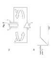
- FIG. 3( a )is a diagram schematically showing an oscillation loop of a vibrator 1 .
- FIG. 3( b )is a diagram schematically showing the change of signal level at a point “a” over time.
- FIG. 4( a )is a diagram schematically showing the change of signal level at a point “a” over time when a rectangular wave is used.
- FIG. 4( b )is a diagram schematically showing the characteristic of amplification of an alternating current amplifier.
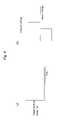
- FIG. 5is a circuit diagram showing a self-oscillating circuit 9 B according to another embodiment of the first aspect of the present invention.
- FIG. 6is a circuit diagram showing a self-oscillating circuit 9 C according to an embodiment of the second aspect of the present invention.
- FIG. 7( a )is a circuit diagram showing a ring oscillator 10 .
- FIG. 7( b )is a diagram schematically showing modulation of rectangular wave at points “A” and “B”.
- FIG. 8is a diagram showing a self-oscillating circuit 9 D according to still another embodiment of the present invention.
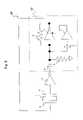
- FIG. 9is a block diagram showing the whole of a control circuit for a vibrator.
- FIG. 1is a diagram schematically showing a self-oscillation circuit 9 A according to one embodiment of the first aspect of the present invention.
- a exciting means 2is equipped with a vibrator 1 and connected with the self-oscillation circuit 9 A to form an oscillation loop.
- the circuitis activated when a gain of a current/voltage amplifier (alternating current amplifier) 3 in the self-oscillation circuit 9 A is large. Only noise is input into the amplifier 3 at the time.
- alternating current amplifieralternating current amplifier
- the vibrator 1is made of a piezoelectric single crystal, for example, as described later.
- the vibrator 1acts as a frequency filter so that a signal substantially containing a vibration of a natural resonance frequency is output as an arrow “D”.
- the signal “D”is input into the amplifier 3 .
- the operationsare repeated in the oscillation loop to improve the ratio of the signal having a natural resonance frequency, so that the amplitude of the input signal to the amplifier 3 is increased.
- the gain of the amplifier 3is adjusted so that the loop gain (gain when the signal is circulated once in the oscillation loop) is adjusted to be 1. Finally, the loop gain reached 1 without adjusting the gain of the amplifier. At this point, the oscillation of the vibrator is stabilized.
- the stable oscillation of the vibratoris indispensable for measurement of a physical value due to the following reasons. If the amplitude of the driving signal for oscillating the vibrator is not constant, the amplitude of the detection signal output by the vibrator is also not constant preventing the accurate measurement of the physical value.
- the amplifier 3is serially connected with a resistor 4 and a CR oscillation circuit 5 A.
- the characteristics of the CR oscillation circuit 5 Ais described referring to FIGS. 2( a ) and 2 ( b ).
- the CR oscillation circuit 5 Ahas a condenser 8 , an alternating current amplifier 7 and a resistor 6 . It is now provided that the rectangular wave has an input wave form as shown in “B” in FIG. 2( b ) at a position “B” in the CR oscillation circuit 5 A.
- the output wave formis sharpened as shown in “A” of FIG. 2( b ) and its amplitude is increased at a position “A”.
- Such self-oscillation circuit using a CR oscillation circuitis suitable for rapidly activating a vibrator due to the following reasons.
- FIG. 3( a )it is provided that the vibrator 1 is excited using the self-oscillation circuit.
- the signal wavehas a wave form of a sine wave
- the signal level at the point “a”is gradually increased over time as described above and then stabilized (loop gain reaches 1).
- the amplifier 3exhibits linear amplification characteristic.
- the signal level at the point “a”may not be substantially increased over time due to the following reasons as shown in FIG. 4 .
- the amplification characteristic of the amplifierhas a lower threshold (lower limit) as shown in FIG. 4( b ). The signal level cannot be amplified in a short time if the initial level of the signal wave is low.
- the signal wavecan be easily amplified during the rectangular wave for the driving signal is looped as arrows “C” and “D”, by providing the CR oscillation circuit in the self-oscillation circuit 9 A, even when the initial level of the signal wave is low.
- the driving vibration of the vibratorcan be activated in a short time by utilizing the characteristics of the CR oscillation circuit.
- the CR oscillation circuitis automatically separated from the oscillation from the self-oscillation circuit without switching.
- the present inventionis superior in that the driving signal of rectangular wave can be applied on the vibrator in a short time period without the need of the dedicated oscillator and switching mechanism.
- FIG. 5is a circuit diagram showing a self-oscillating circuit 9 B according to the first aspect of the present invention.
- a CR oscillation circuit 5 B used in the present examplealso has a condenser 8 , an amplifier 7 and a resistor 6 .
- the amplifier 7 and condenser 8are serially connected in the present example.
- FIG. 6is a circuit diagram showing a self oscillating circuit 9 C according to an embodiment of the second aspect of the present invention.
- a ring oscillator 10is connected instead of the above CR oscillation circuit. That is, a plurality of amplifiers 10 a, 10 b and 10 c are serially connected with each other to produce the ring oscillator 10 .
- the ring oscillator 10is serially connected with the condenser 8 and connected with the resistor 6 in parallel.
- the characteristics of the ring oscillator 10is schematically shown in FIGS. 7( a ) and ( b ). Rectangular wave at the point “B” in the upstream of the ring oscillator 10 is output at the point “A” as rectangular wave with the phase delayed as arrows. The phase of the rectangular wave is made delayed at a predetermined time period in the ring oscillator 10 , and the ring oscillator 10 is connected with the self-oscillator 10 . It is thus possible to amplify the signal of a specific frequency in the ring oscillator 10 .
- FIG. 8is a circuit diagram showing another self-oscillation circuit 9 D according to an embodiment of the first aspect of the present invention.
- the circuit of the present exampleis substantially same as the self-oscillating circuit 9 B of FIG. 5 , except that the circuit is ground through a resistor 4 in the present example.
- an accumulator 11is connected with an accumulator 7 to provide a comparator.
- a standard voltage lineis connected to the accumulator 11 . The amplitude of the signal in the circuit is judged by the accumulator 11 , and, responsive to this, the gain in the amplifier 7 is controlled.
- the self-oscillation circuithas an alternating current amplifier for frequency control and a circuit for controlling amplitude (AGC circuit).
- AGC circuita circuit for controlling amplitude
- the deviation of the amplitudeis prevented to output a signal having a constant value of amplitude.
- FIG. 9is a block diagram schematically showing a control circuit of a vibrator usable in the present invention.
- the control circuit 31has a driving circuit 32 and a detection circuit 33 .
- the driving circuit 32is provided for exciting a driving vibration part 1 a of a vibrator 1 .
- the driving circuit 32has self-oscillation circuits 9 A, 9 B, 9 C or 9 D and a diagnosis circuit 29 .
- a noiseis input from an activation circuit to the self-oscillation circuit.
- the noisepasses through the driving vibration part 1 a of the vibrator and subject to frequency selection, and then input into the alternating current amplifier 3 of the self-oscillation circuit for subsequent amplification as an arrow “D”.
- a part of the output signal from the alternating current amplifier 3is drawn and input to a rectifier to convert the signal to the amplitude value of the signal.
- the signal of amplitude valueis input to the CR oscillation circuit or ring oscillator.
- the self-oscillation circuitis connected to the diagnosis circuit 29 , and the output of the diagnosis circuit 29 is output through a DIAG terminal to the outside.
- a substantial portion of the noiseis cut in the vibrator 1 a direct after the activation, so that the output from the rectifier is relatively low.
- the gain in the amplifieris made large so that a loop gain during one oscillation loop is adjusted at 1. Since the output from the rectifier becomes larger over time, the gain in the amplifier is made lower so that the loop gain is adjusted at 1.
- the detection of signals by detection parts 1 b and 1 c of the vibratoris started. That is, detection signals (alternating current) from the detection parts 1 b and 1 c of the vibrator are amplified using alternating current amplifiers 21 A and 21 B. Outputs from the amplifiers 21 A and 21 B are added by an adder 22 .
- a part of a driving signalis derivated and the thus derivated signal is supplied to a phase shifter 23 to obtain to a sifted signal.
- the phase of the shifted signalis different from that of a leakage signal at a predetermined angle, for example, 90°.
- the shifted signalis input into a phase detector 14 to detect the output signal from the vibrator. As a result, unnecessary leakage signal should be cancelled or at least reduced in the output signal after the phase detection.
- the output signal after the phase detectionis input into a low path filter 17 and smoothed and then input into a zero point adjusting circuit 18 . The output is drawn to the outside.
- the construction of the vibratoris not particularly limited.
- the Q value of a material for the vibratormay preferably be 3000 or higher, and more preferably be 10000 or higher.
- the material for the vibratorincludes a permanent elastic alloy such as elinver and a ferroelectric single crystal (piezoelectric single crystal).
- a permanent elastic alloysuch as elinver and a ferroelectric single crystal (piezoelectric single crystal).
- piezoelectric single crystalpiezoelectric single crystal
- Such single crystalincludes quartz, lithium niobate, lithium tantalate, lithium niobate-lithium tantalate solid solution, lithium borate and langasite.
- a physical value measured according to the present inventionis not particularly limited.
- the physical valueis included in the present invention as far as the physical value can be detected through a detection circuit.
- Such physical valuemay preferably be an acceleration, an angular acceleration or an angular velocity applied on a vibrator.
- the measuring system of the present inventionmay preferably be an inertia censor.
- a vibrator described in Japanese patent publication 11-281372Awas used.
- the vibratorhad two driving vibration pieces 1 a, and two detection vibration pieces 1 b and 1 c vibrating independently from the driving vibration pieces.
- Noise in a frequency range of 100 to 500 kHzwas generated from the activation circuit, and then input into the oscillation loop to activate self-oscillation.
- the delay time of the comparatorwas 1.0 ⁇ s (500 kHz), the amplitude of output was 2Vp-p, and the width of dead zone voltage was 5 mV.
- the resistance of the resistor 6was 10 M ⁇ , and the capacity of the condenser 8 was 10 pF (1 MHz).
- a time period required for stabilizing the oscillation of the driving signalwas about 0.160 seconds.
- the amplitude of the driving signalwas 1.1 V and the frequency was 44.1 kHz.
- the present inventionprovides a method and system suitable for applying a driving signal of rectangular wave on a vibrator to excite a driving vibration in the vibrator.
Landscapes
- Physics & Mathematics (AREA)
- Engineering & Computer Science (AREA)
- General Physics & Mathematics (AREA)
- Radar, Positioning & Navigation (AREA)
- Remote Sensing (AREA)
- Gyroscopes (AREA)
Abstract
Description
Claims (4)
Applications Claiming Priority (2)
| Application Number | Priority Date | Filing Date | Title |
|---|---|---|---|
| JP2003077155AJP4336946B2 (en) | 2003-03-20 | 2003-03-20 | Method and apparatus for measuring rotational angular velocity |
| JPP2003-077155 | 2003-03-20 |
Publications (2)
| Publication Number | Publication Date |
|---|---|
| US20040182184A1 US20040182184A1 (en) | 2004-09-23 |
| US7089793B2true US7089793B2 (en) | 2006-08-15 |
Family
ID=32821371
Family Applications (1)
| Application Number | Title | Priority Date | Filing Date |
|---|---|---|---|
| US10/803,176Expired - LifetimeUS7089793B2 (en) | 2003-03-20 | 2004-03-17 | Method and system of exciting a driving vibration in a vibrator |
Country Status (4)
| Country | Link |
|---|---|
| US (1) | US7089793B2 (en) |
| EP (1) | EP1460380B1 (en) |
| JP (1) | JP4336946B2 (en) |
| CN (1) | CN100489454C (en) |
Cited By (6)
| Publication number | Priority date | Publication date | Assignee | Title |
|---|---|---|---|---|
| US20080087084A1 (en)* | 2006-10-17 | 2008-04-17 | Seiko Epson Corporation | Driver device, physical quantity measuring device, and electronic instrument |
| US20080105054A1 (en)* | 2006-11-06 | 2008-05-08 | Seiko Epson Corporation | Driver device, physical quantity measuring device, and electronic instrument |
| US20090160763A1 (en)* | 2007-12-21 | 2009-06-25 | Patrick Cauwels | Haptic Response Apparatus for an Electronic Device |
| US20100206074A1 (en)* | 2009-02-19 | 2010-08-19 | Seiko Epson Corporation | Oscillation drive device, physical quantity measurement device and electronic apparatus |
| US8265308B2 (en) | 2007-12-07 | 2012-09-11 | Motorola Mobility Llc | Apparatus including two housings and a piezoelectric transducer |
| US20140305205A1 (en)* | 2013-04-12 | 2014-10-16 | Samsung Electro-Mechanics Co., Ltd. | Self-oscillation circuit and method thereof |
Families Citing this family (38)
| Publication number | Priority date | Publication date | Assignee | Title |
|---|---|---|---|---|
| KR20060129930A (en)* | 2004-01-20 | 2006-12-18 | 니뽄 가이시 가부시키가이샤 | Detection circuit, detection method and physical quantity measuring device |
| US7849744B2 (en) | 2006-08-02 | 2010-12-14 | Seiko Epson Corporation | Driving device, physical quantity measurement device, and electronic instrument |
| JP4930253B2 (en)* | 2006-08-02 | 2012-05-16 | セイコーエプソン株式会社 | Drive device, physical quantity measuring device and electronic device |
| JP2008089577A (en) | 2006-09-08 | 2008-04-17 | Seiko Epson Corp | Drive device, physical quantity measuring device and electronic device |
| JP5200491B2 (en)* | 2006-11-06 | 2013-06-05 | セイコーエプソン株式会社 | Drive device, physical quantity measuring device and electronic device |
| US8026771B2 (en) | 2006-11-27 | 2011-09-27 | Seiko Epson Corporation | Driver device, physical quantity measuring device, and electronic instrument |
| JP5136016B2 (en) | 2006-11-27 | 2013-02-06 | セイコーエプソン株式会社 | Drive device, physical quantity measuring device and electronic device |
| US7692506B2 (en) | 2007-08-01 | 2010-04-06 | Seiko Epson Corporation | Oscillation driver device, physical quantity measuring device, and electronic instrument |
| CN101809408A (en)* | 2007-09-25 | 2010-08-18 | 罗姆股份有限公司 | Angular velocity detecting device and method for manufacturing angular velocity detecting device |
| US8710599B2 (en) | 2009-08-04 | 2014-04-29 | Fairchild Semiconductor Corporation | Micromachined devices and fabricating the same |
| GB201005875D0 (en) | 2010-04-08 | 2010-05-26 | Silicon Sensing Systems Ltd | Sensors |
| CN103221778B (en) | 2010-09-18 | 2016-03-30 | 快捷半导体公司 | There is single micromechanics one chip three-axis gyroscope driven |
| US9095072B2 (en) | 2010-09-18 | 2015-07-28 | Fairchild Semiconductor Corporation | Multi-die MEMS package |
| CN103221779B (en) | 2010-09-18 | 2017-05-31 | 快捷半导体公司 | The axle inertial sensor of micromechanics monoblock type six |
| WO2012037536A2 (en) | 2010-09-18 | 2012-03-22 | Fairchild Semiconductor Corporation | Packaging to reduce stress on microelectromechanical systems |
| US9278845B2 (en) | 2010-09-18 | 2016-03-08 | Fairchild Semiconductor Corporation | MEMS multi-axis gyroscope Z-axis electrode structure |
| KR101443730B1 (en) | 2010-09-18 | 2014-09-23 | 페어차일드 세미컨덕터 코포레이션 | A microelectromechanical die, and a method for making a low-quadrature-error suspension |
| WO2012040245A2 (en) | 2010-09-20 | 2012-03-29 | Fairchild Semiconductor Corporation | Through silicon via with reduced shunt capacitance |
| WO2012040211A2 (en) | 2010-09-20 | 2012-03-29 | Fairchild Semiconductor Corporation | Microelectromechanical pressure sensor including reference capacitor |
| US9062972B2 (en) | 2012-01-31 | 2015-06-23 | Fairchild Semiconductor Corporation | MEMS multi-axis accelerometer electrode structure |
| US8978475B2 (en) | 2012-02-01 | 2015-03-17 | Fairchild Semiconductor Corporation | MEMS proof mass with split z-axis portions |
| JP5729323B2 (en)* | 2012-02-09 | 2015-06-03 | 株式会社デンソー | Self-excited resonant circuit |
| US8754694B2 (en) | 2012-04-03 | 2014-06-17 | Fairchild Semiconductor Corporation | Accurate ninety-degree phase shifter |
| KR102048393B1 (en)* | 2012-04-03 | 2019-11-25 | 페어차일드 세미컨덕터 코포레이션 | Accurate ninety degree phase shifter |
| US8742964B2 (en) | 2012-04-04 | 2014-06-03 | Fairchild Semiconductor Corporation | Noise reduction method with chopping for a merged MEMS accelerometer sensor |
| US9488693B2 (en) | 2012-04-04 | 2016-11-08 | Fairchild Semiconductor Corporation | Self test of MEMS accelerometer with ASICS integrated capacitors |
| EP2647955B8 (en) | 2012-04-05 | 2018-12-19 | Fairchild Semiconductor Corporation | MEMS device quadrature phase shift cancellation |
| KR102058489B1 (en) | 2012-04-05 | 2019-12-23 | 페어차일드 세미컨덕터 코포레이션 | Mems device front-end charge amplifier |
| EP2647952B1 (en) | 2012-04-05 | 2017-11-15 | Fairchild Semiconductor Corporation | Mems device automatic-gain control loop for mechanical amplitude drive |
| US9069006B2 (en) | 2012-04-05 | 2015-06-30 | Fairchild Semiconductor Corporation | Self test of MEMS gyroscope with ASICs integrated capacitors |
| US9625272B2 (en) | 2012-04-12 | 2017-04-18 | Fairchild Semiconductor Corporation | MEMS quadrature cancellation and signal demodulation |
| US9094027B2 (en) | 2012-04-12 | 2015-07-28 | Fairchild Semiconductor Corporation | Micro-electro-mechanical-system (MEMS) driver |
| DE102013014881B4 (en) | 2012-09-12 | 2023-05-04 | Fairchild Semiconductor Corporation | Enhanced silicon via with multi-material fill |
| JP6032243B2 (en)* | 2014-05-23 | 2016-11-24 | 横河電機株式会社 | Current-voltage conversion circuit and self-excited oscillation circuit |
| JP6570428B2 (en) | 2015-11-09 | 2019-09-04 | セイコーエプソン株式会社 | Physical quantity detection device, electronic device and moving object |
| CN107104637B (en)* | 2016-02-19 | 2021-03-12 | 横河电机株式会社 | self-oscillating circuit |
| CN110470291B (en)* | 2019-09-04 | 2023-11-24 | 中国海洋大学 | A MEMS resonant gyroscope interface circuit and measurement and control system |
| CN113296397B (en)* | 2021-07-27 | 2021-10-29 | 中国人民解放军国防科技大学 | Method and device for rapid start-up of gyroscope based on parameter excitation |
Citations (12)
| Publication number | Priority date | Publication date | Assignee | Title |
|---|---|---|---|---|
| US3805592A (en)* | 1970-08-20 | 1974-04-23 | Itt | Densitometer |
| US4020330A (en)* | 1976-05-03 | 1977-04-26 | International Telephone And Telegraph Corporation | Densitometer |
| US5365768A (en)* | 1989-07-20 | 1994-11-22 | Hitachi, Ltd. | Sensor |
| DE19811025A1 (en) | 1998-03-13 | 1999-09-16 | Hahn Schickard Ges | Mechanical oscillator e.g. for mechanical or micromechanical rotation rate sensor |
| JPH11281372A (en) | 1997-11-04 | 1999-10-15 | Ngk Insulators Ltd | Vibrator, vibration gyroscope, linear accelerator, and method for measuring rotary angular velocity |
| US6081166A (en)* | 1997-08-21 | 2000-06-27 | Sony Corporation | Voltage controlled oscillator including a plurality of buffer circuits diodes, current sources, MIS capacitors |
| US20010000853A1 (en) | 1996-02-21 | 2001-05-10 | Fujitsu Limited | Tuning-fork vibratory gyro |
| EP1189023A2 (en) | 2000-09-15 | 2002-03-20 | BEI Technologies, Inc. | Inertial rate sensor and method with improved tuning fork drive |
| US6397656B1 (en)* | 1999-01-25 | 2002-06-04 | Yamatake Corporation | System and method for detecting liquid serving as object to be detected in vessel using ultrasonic sensor |
| US6450029B1 (en)* | 1999-09-27 | 2002-09-17 | Denso Corporation | Capacitive physical quantity detection device |
| US20030006784A1 (en) | 2000-08-02 | 2003-01-09 | Paul Ward | Drive feedthrough nulling system |
| JP2003021518A (en) | 2001-07-09 | 2003-01-24 | Ngk Insulators Ltd | Measuring method using vibrator, measuring device and drive device of the vibrator |
Family Cites Families (7)
| Publication number | Priority date | Publication date | Assignee | Title |
|---|---|---|---|---|
| JP3235006B2 (en)* | 1993-10-28 | 2001-12-04 | 日本プレシジョン・サーキッツ株式会社 | Oscillation integrated circuit |
| JPH0933262A (en)* | 1995-07-25 | 1997-02-07 | Nikon Corp | Excitation drive circuit and method, and piezoelectric vibration angular velocity meter using the same |
| US5630216A (en)* | 1994-09-06 | 1997-05-13 | The Regents Of The University Of California | Micropower RF transponder with superregenerative receiver and RF receiver with sampling mixer |
| JPH10221083A (en)* | 1997-02-05 | 1998-08-21 | Murata Mfg Co Ltd | Vibration-type gyro apparatus |
| JP3718786B2 (en)* | 1997-02-17 | 2005-11-24 | 日本航空電子工業株式会社 | Vibrating gyro |
| JP4361174B2 (en)* | 1999-09-16 | 2009-11-11 | セイコーエプソン株式会社 | Vibrating gyroscope |
| JP2003032039A (en)* | 2001-07-16 | 2003-01-31 | Toyo Commun Equip Co Ltd | Piezoelectric oscillation circuit |
- 2003
- 2003-03-20JPJP2003077155Apatent/JP4336946B2/ennot_activeExpired - Lifetime
- 2004
- 2004-03-17USUS10/803,176patent/US7089793B2/ennot_activeExpired - Lifetime
- 2004-03-19CNCNB2004100304361Apatent/CN100489454C/ennot_activeExpired - Lifetime
- 2004-03-19EPEP04251600.5Apatent/EP1460380B1/ennot_activeExpired - Lifetime
Patent Citations (12)
| Publication number | Priority date | Publication date | Assignee | Title |
|---|---|---|---|---|
| US3805592A (en)* | 1970-08-20 | 1974-04-23 | Itt | Densitometer |
| US4020330A (en)* | 1976-05-03 | 1977-04-26 | International Telephone And Telegraph Corporation | Densitometer |
| US5365768A (en)* | 1989-07-20 | 1994-11-22 | Hitachi, Ltd. | Sensor |
| US20010000853A1 (en) | 1996-02-21 | 2001-05-10 | Fujitsu Limited | Tuning-fork vibratory gyro |
| US6081166A (en)* | 1997-08-21 | 2000-06-27 | Sony Corporation | Voltage controlled oscillator including a plurality of buffer circuits diodes, current sources, MIS capacitors |
| JPH11281372A (en) | 1997-11-04 | 1999-10-15 | Ngk Insulators Ltd | Vibrator, vibration gyroscope, linear accelerator, and method for measuring rotary angular velocity |
| DE19811025A1 (en) | 1998-03-13 | 1999-09-16 | Hahn Schickard Ges | Mechanical oscillator e.g. for mechanical or micromechanical rotation rate sensor |
| US6397656B1 (en)* | 1999-01-25 | 2002-06-04 | Yamatake Corporation | System and method for detecting liquid serving as object to be detected in vessel using ultrasonic sensor |
| US6450029B1 (en)* | 1999-09-27 | 2002-09-17 | Denso Corporation | Capacitive physical quantity detection device |
| US20030006784A1 (en) | 2000-08-02 | 2003-01-09 | Paul Ward | Drive feedthrough nulling system |
| EP1189023A2 (en) | 2000-09-15 | 2002-03-20 | BEI Technologies, Inc. | Inertial rate sensor and method with improved tuning fork drive |
| JP2003021518A (en) | 2001-07-09 | 2003-01-24 | Ngk Insulators Ltd | Measuring method using vibrator, measuring device and drive device of the vibrator |
Cited By (10)
| Publication number | Priority date | Publication date | Assignee | Title |
|---|---|---|---|---|
| US20080087084A1 (en)* | 2006-10-17 | 2008-04-17 | Seiko Epson Corporation | Driver device, physical quantity measuring device, and electronic instrument |
| US7812681B2 (en) | 2006-10-17 | 2010-10-12 | Seiko) Epson Corporation | Driver device, physical quantity measuring device, and electronic instrument |
| US20080105054A1 (en)* | 2006-11-06 | 2008-05-08 | Seiko Epson Corporation | Driver device, physical quantity measuring device, and electronic instrument |
| US7895894B2 (en) | 2006-11-06 | 2011-03-01 | Seiko Epson Corporation | Driver device, physical quantity measuring device, and electronic instrument |
| US8265308B2 (en) | 2007-12-07 | 2012-09-11 | Motorola Mobility Llc | Apparatus including two housings and a piezoelectric transducer |
| US20090160763A1 (en)* | 2007-12-21 | 2009-06-25 | Patrick Cauwels | Haptic Response Apparatus for an Electronic Device |
| US8395587B2 (en) | 2007-12-21 | 2013-03-12 | Motorola Mobility Llc | Haptic response apparatus for an electronic device |
| US20100206074A1 (en)* | 2009-02-19 | 2010-08-19 | Seiko Epson Corporation | Oscillation drive device, physical quantity measurement device and electronic apparatus |
| US8618889B2 (en) | 2009-02-19 | 2013-12-31 | Seiko Epson Corporation | Oscillation drive device, physical quantity measurement device and electronic apparatus |
| US20140305205A1 (en)* | 2013-04-12 | 2014-10-16 | Samsung Electro-Mechanics Co., Ltd. | Self-oscillation circuit and method thereof |
Also Published As
| Publication number | Publication date |
|---|---|
| CN1532524A (en) | 2004-09-29 |
| JP4336946B2 (en) | 2009-09-30 |
| EP1460380B1 (en) | 2017-08-23 |
| US20040182184A1 (en) | 2004-09-23 |
| CN100489454C (en) | 2009-05-20 |
| JP2004286503A (en) | 2004-10-14 |
| EP1460380A1 (en) | 2004-09-22 |
Similar Documents
| Publication | Publication Date | Title |
|---|---|---|
| US7089793B2 (en) | Method and system of exciting a driving vibration in a vibrator | |
| US8618889B2 (en) | Oscillation drive device, physical quantity measurement device and electronic apparatus | |
| US4056761A (en) | Sonic transducer and drive circuit | |
| US6510737B1 (en) | Inertial rate sensor and method with improved tuning fork drive | |
| US7849744B2 (en) | Driving device, physical quantity measurement device, and electronic instrument | |
| US7849746B2 (en) | Driver device, physical quantity measuring device, and electronic instrument | |
| US7812681B2 (en) | Driver device, physical quantity measuring device, and electronic instrument | |
| US7370531B2 (en) | Detection circuits, detection method and systems of measuring physical quantities | |
| JP4573017B2 (en) | Detection method and detection apparatus using vibrator | |
| JP4449262B2 (en) | Measuring method, measuring apparatus using vibrator, and driving apparatus for vibrator | |
| JP4075152B2 (en) | Angular velocity sensor | |
| US7441458B2 (en) | Systems for measuring physical quantities | |
| JP2000028364A (en) | Angular velocity sensor device and driving method thereof | |
| JP4930253B2 (en) | Drive device, physical quantity measuring device and electronic device | |
| US11118906B2 (en) | Oscillator circuit including oscillator | |
| JP2008089572A (en) | Drive device, physical quantity measuring device and electronic device | |
| JP2003240556A (en) | Measuring device of physical quantity and drive device of vibrator | |
| US7140251B2 (en) | Devices for measuring physical values and vibrators | |
| JP4337008B2 (en) | Method and apparatus for measuring rotational angular velocity | |
| JP2000292172A (en) | Driving and detecting device for piezoelectric vibrator | |
| JP2005345109A (en) | Method and instrument for measuring physical quantity | |
| JPH1151657A (en) | Excitation circuit of piezoelectric vibration type angular velocity sensor | |
| JP2003057037A (en) | Method and apparatus for measurement of physical quantity as well as method for supply of electric power to physical-quantity measuring apparatus |
Legal Events
| Date | Code | Title | Description |
|---|---|---|---|
| AS | Assignment | Owner name:SEIKO EPSON CORPORATION, JAPAN Free format text:ASSIGNMENT OF ASSIGNORS INTEREST;ASSIGNORS:YOKOI, SHOJI;KOBAYASHI, YOSHIHIRO;REEL/FRAME:015276/0019;SIGNING DATES FROM 20040408 TO 20040414 Owner name:NGK INSULATORS, LTD., JAPAN Free format text:ASSIGNMENT OF ASSIGNORS INTEREST;ASSIGNORS:YOKOI, SHOJI;KOBAYASHI, YOSHIHIRO;REEL/FRAME:015276/0019;SIGNING DATES FROM 20040408 TO 20040414 | |
| STCF | Information on status: patent grant | Free format text:PATENTED CASE | |
| AS | Assignment | Owner name:SEIKO EPSON CORPORATION, JAPAN Free format text:ASSIGNMENT OF ASSIGNORS INTEREST;ASSIGNOR:NGK INSULATORS, LTD.;REEL/FRAME:021785/0357 Effective date:20080901 | |
| FEPP | Fee payment procedure | Free format text:PAYOR NUMBER ASSIGNED (ORIGINAL EVENT CODE: ASPN); ENTITY STATUS OF PATENT OWNER: LARGE ENTITY | |
| FPAY | Fee payment | Year of fee payment:4 | |
| FPAY | Fee payment | Year of fee payment:8 | |
| MAFP | Maintenance fee payment | Free format text:PAYMENT OF MAINTENANCE FEE, 12TH YEAR, LARGE ENTITY (ORIGINAL EVENT CODE: M1553) Year of fee payment:12 |