US7089577B1 - Process for supplying video-on-demand and other requested programs and services from a headend - Google Patents
Process for supplying video-on-demand and other requested programs and services from a headendDownload PDFInfo
- Publication number
- US7089577B1 US7089577B1US09/602,779US60277900AUS7089577B1US 7089577 B1US7089577 B1US 7089577B1US 60277900 AUS60277900 AUS 60277900AUS 7089577 B1US7089577 B1US 7089577B1
- Authority
- US
- United States
- Prior art keywords
- data
- video
- packets
- programs
- requested
- Prior art date
- Legal status (The legal status is an assumption and is not a legal conclusion. Google has not performed a legal analysis and makes no representation as to the accuracy of the status listed.)
- Expired - Lifetime, expires
Links
- 238000000034methodMethods0.000titleclaimsdescription49
- 230000008569processEffects0.000titleclaimsdescription48
- 238000011144upstream manufacturingMethods0.000claimsabstractdescription138
- 230000005540biological transmissionEffects0.000claimsdescription32
- 239000000835fiberSubstances0.000claimsdescription14
- 238000013507mappingMethods0.000claimsdescription10
- 230000008878couplingEffects0.000claimsdescription7
- 238000010168coupling processMethods0.000claimsdescription7
- 238000005859coupling reactionMethods0.000claimsdescription7
- 238000009826distributionMethods0.000claimsdescription6
- 230000006837decompressionEffects0.000claims1
- 230000002093peripheral effectEffects0.000description33
- 238000007726management methodMethods0.000description31
- 241000167854Bourreria succulentaSpecies0.000description26
- 235000019693cherriesNutrition0.000description26
- 238000012545processingMethods0.000description20
- 230000002457bidirectional effectEffects0.000description18
- 230000006870functionEffects0.000description15
- 238000012360testing methodMethods0.000description15
- 230000006835compressionEffects0.000description11
- 238000007906compressionMethods0.000description11
- 241000894007speciesSpecies0.000description10
- 238000010586diagramMethods0.000description9
- 239000013598vectorSubstances0.000description8
- 239000012634fragmentSubstances0.000description6
- 101150012579ADSL geneProteins0.000description5
- 102100020775Adenylosuccinate lyaseHuman genes0.000description5
- 108700040193Adenylosuccinate lyasesProteins0.000description5
- 241000196324EmbryophytaSpecies0.000description5
- 239000000969carrierSubstances0.000description5
- 238000005538encapsulationMethods0.000description5
- 230000002452interceptive effectEffects0.000description5
- 238000001228spectrumMethods0.000description5
- 238000004891communicationMethods0.000description3
- 238000005516engineering processMethods0.000description3
- 230000005236sound signalEffects0.000description3
- 230000004075alterationEffects0.000description2
- 238000013461designMethods0.000description2
- 238000012986modificationMethods0.000description2
- 230000004048modificationEffects0.000description2
- 230000001360synchronised effectEffects0.000description2
- RYGMFSIKBFXOCR-UHFFFAOYSA-NCopperChemical compound[Cu]RYGMFSIKBFXOCR-UHFFFAOYSA-N0.000description1
- 238000012952ResamplingMethods0.000description1
- 241001263038ViguieraSpecies0.000description1
- 230000002411adverseEffects0.000description1
- 238000013459approachMethods0.000description1
- 230000001413cellular effectEffects0.000description1
- 230000008859changeEffects0.000description1
- 239000002131composite materialSubstances0.000description1
- 229910052802copperInorganic materials0.000description1
- 239000010949copperSubstances0.000description1
- 238000012937correctionMethods0.000description1
- 230000003247decreasing effectEffects0.000description1
- 230000002074deregulated effectEffects0.000description1
- 238000011161developmentMethods0.000description1
- 238000003745diagnosisMethods0.000description1
- 230000000694effectsEffects0.000description1
- 238000007519figuringMethods0.000description1
- 238000001914filtrationMethods0.000description1
- 238000004519manufacturing processMethods0.000description1
- 230000008520organizationEffects0.000description1
- 238000012552reviewMethods0.000description1
- 230000011664signalingEffects0.000description1
- 238000000638solvent extractionMethods0.000description1
- 238000003860storageMethods0.000description1
Images


Classifications
- H—ELECTRICITY
- H04—ELECTRIC COMMUNICATION TECHNIQUE
- H04N—PICTORIAL COMMUNICATION, e.g. TELEVISION
- H04N7/00—Television systems
- H04N7/16—Analogue secrecy systems; Analogue subscription systems
- H04N7/173—Analogue secrecy systems; Analogue subscription systems with two-way working, e.g. subscriber sending a programme selection signal
- H04N7/17309—Transmission or handling of upstream communications
- H04N7/17336—Handling of requests in head-ends
- H—ELECTRICITY
- H04—ELECTRIC COMMUNICATION TECHNIQUE
- H04N—PICTORIAL COMMUNICATION, e.g. TELEVISION
- H04N21/00—Selective content distribution, e.g. interactive television or video on demand [VOD]
- H04N21/20—Servers specifically adapted for the distribution of content, e.g. VOD servers; Operations thereof
- H04N21/23—Processing of content or additional data; Elementary server operations; Server middleware
- H04N21/235—Processing of additional data, e.g. scrambling of additional data or processing content descriptors
- H—ELECTRICITY
- H04—ELECTRIC COMMUNICATION TECHNIQUE
- H04N—PICTORIAL COMMUNICATION, e.g. TELEVISION
- H04N21/00—Selective content distribution, e.g. interactive television or video on demand [VOD]
- H04N21/20—Servers specifically adapted for the distribution of content, e.g. VOD servers; Operations thereof
- H04N21/23—Processing of content or additional data; Elementary server operations; Server middleware
- H04N21/236—Assembling of a multiplex stream, e.g. transport stream, by combining a video stream with other content or additional data, e.g. inserting a URL [Uniform Resource Locator] into a video stream, multiplexing software data into a video stream; Remultiplexing of multiplex streams; Insertion of stuffing bits into the multiplex stream, e.g. to obtain a constant bit-rate; Assembling of a packetised elementary stream
- H04N21/23614—Multiplexing of additional data and video streams
- H—ELECTRICITY
- H04—ELECTRIC COMMUNICATION TECHNIQUE
- H04N—PICTORIAL COMMUNICATION, e.g. TELEVISION
- H04N21/00—Selective content distribution, e.g. interactive television or video on demand [VOD]
- H04N21/40—Client devices specifically adapted for the reception of or interaction with content, e.g. set-top-box [STB]; Operations thereof
- H04N21/43—Processing of content or additional data, e.g. demultiplexing additional data from a digital video stream; Elementary client operations, e.g. monitoring of home network or synchronising decoder's clock; Client middleware
- H04N21/435—Processing of additional data, e.g. decrypting of additional data, reconstructing software from modules extracted from the transport stream
- H—ELECTRICITY
- H04—ELECTRIC COMMUNICATION TECHNIQUE
- H04N—PICTORIAL COMMUNICATION, e.g. TELEVISION
- H04N21/00—Selective content distribution, e.g. interactive television or video on demand [VOD]
- H04N21/40—Client devices specifically adapted for the reception of or interaction with content, e.g. set-top-box [STB]; Operations thereof
- H04N21/47—End-user applications
- H04N21/472—End-user interface for requesting content, additional data or services; End-user interface for interacting with content, e.g. for content reservation or setting reminders, for requesting event notification, for manipulating displayed content
- H—ELECTRICITY
- H04—ELECTRIC COMMUNICATION TECHNIQUE
- H04N—PICTORIAL COMMUNICATION, e.g. TELEVISION
- H04N21/00—Selective content distribution, e.g. interactive television or video on demand [VOD]
- H04N21/40—Client devices specifically adapted for the reception of or interaction with content, e.g. set-top-box [STB]; Operations thereof
- H04N21/47—End-user applications
- H04N21/488—Data services, e.g. news ticker
- H04N21/4882—Data services, e.g. news ticker for displaying messages, e.g. warnings, reminders
- H—ELECTRICITY
- H04—ELECTRIC COMMUNICATION TECHNIQUE
- H04N—PICTORIAL COMMUNICATION, e.g. TELEVISION
- H04N21/00—Selective content distribution, e.g. interactive television or video on demand [VOD]
- H04N21/60—Network structure or processes for video distribution between server and client or between remote clients; Control signalling between clients, server and network components; Transmission of management data between server and client, e.g. sending from server to client commands for recording incoming content stream; Communication details between server and client
- H04N21/61—Network physical structure; Signal processing
- H04N21/6106—Network physical structure; Signal processing specially adapted to the downstream path of the transmission network
- H04N21/6125—Network physical structure; Signal processing specially adapted to the downstream path of the transmission network involving transmission via Internet
Definitions
- the inventionfinds utility in the head end offices of cable TV operators, ADSL system head end and potentially wireless head ends for delivery of video-on-demand programming in digital format as well as other services such as digital telephony or wideband internet access.
- DIGITAL SERVICESfiled Jan. 14, 2000, Ser. No. 09/483,681 which is hereby incorporated by reference.
- Most cable TV systems in the prior arthave been broadcast only where individual programs were modulated onto 6 MHz bandwidth analog RF carriers that were frequency division multiplexed.
- analog RF carriersthat were frequency division multiplexed.
- Video-on-demand serviceshave been known in hotel television systems for several years. Video-on-demand services allow a user to select a program to view and have the video and audio data of that program transmitted to her television set. Examples of such systems include: U.S. Pat. No. 6,057,832 disclosing a video on demand system with a fast play and a regular play mode; U.S. Pat. No. 6,055,560 disclosing an interactive video-on-demand system that supports functions normally only found on a VCR such as rewind, stop, fast forward etc.; U.S. Pat. No.
- 6,055,314which discloses a system for secure purchase and delivery of video content programs over distribution networks and DVDs involving downloading of decryption keys from the video source when a program is ordered and paid for;
- U.S. Pat. No. 6,049,823disclosing an interactive video-on-demand to deliver interactive multimedia services to a community of users through a LAN or TV over an interactive TV channel;
- U.S. Pat. No. 6,025,868disclosing a pay-per-play system including a high-capacity storage medium;
- 5,935,206teaching a server that provides access to digital video movies for viewing on demand using a bandwidth allocation scheme that compares the number of requests for a program to a threshold and then, under some circumstances of high demand makes another copy of the video movie on another disk where the original disk does not have the bandwidth to serve the movie to all requesters;
- U.S. Pat. No. 5,926,205teaching a video-on-demand system that provides access to a video program by partitioning the program into an ordered sequence of N segments and provides subscribers concurrent access to each of the N segments;
- 5,802,283teaching a public switched telephone network for providing information from multimedia information servers to individual telephone subscribers via a central office that interfaces to the multimedia server(s) and receives subscriber requests and including a gateway for conveying routing data and a switch for routing the multimedia data from the server to the requesting subscriber over first, second and third signal channels of an ADSL link to the subscriber.
- Video-on-demand on cable TV systems to receive requests from cable subsribers for video programs or services such as high speed internet access or access to T1 or other high speed digital telephony serviceshave not yet completed development.
- Such systemsreceive upstream requests and deliver requested video programs with associated audio and other data, as well as bidirectional delivery of internet protocol packets from LAN or WAN sources coupled to the head end bidirectional delivery of telephony data packets to and from T1 or other high speed lines of the public service telephony network.
- a needhas arisen for a video-on-demand service over cable TV systems as well as delivery of other services such as wideband internet and T1 telephony access over cable TV systems.
- a genus of video-on-demand pull technology cable TV systemsis defined herein.
- Each systemincludes one or more “pull multiplexers” and one or more video stream inputs and one or more transmitters or transceivers at the head end, and a plurality of customer premises distributed along the downstream transmission medium.
- a “pull multiplexer”is defined as a head end “cherry picker” multiplexer that has circuitry and/or software which functions to, at least:
- the downstream mediahas sufficient bandwidth that all the requested (and possibly broadcast) programs and/or services can be transmitted without any downward adjustment in the bandwidth of the output streams.
- the downstream mediumis a hybrid fiber coaxial cable CATV plant (hereafter HFC).
- HFChybrid fiber coaxial cable CATV plant
- structure to carry out an additional functionis necessary in the pull multiplexer.
- HFCthere is a fixed maximum amount of bandwidth available, and it must be shared by all the users coupled to the cable. Thus, as the number of requested programs and/or services rise, more and more bandwidth is consumed.
- the pull multiplexerWhen the load rises to the point that the maximum available bandwidth is about to be exceeded, the pull multiplexer must adjust the bandwidth consumption of the output streams to stay within the bandwidth constraints. Generally, this can be done by commercially available resampling chips. Typically, downward adjustment of bandwidth is done by decompressing the compressed data packets and re-compressing them with a different, stricter compression algorithm which results in less quality but lower bandwidth consumption until the desired bandwidth is reached.
- a pull multiplexerdoes all of the above (including bandwidth management if necessary) but automatically includes certain high demand programs in the output stream(s) even if they have not been specifically requested.
- High demand programsare programs that somebody will want to view almost always. These programs are included in one or more output streams at all times in this subgenus of species. The remaining program slots in the channels not consumed by broadcast programs are devoted solely to programs that have been requested and are shared by all users.
- the pull multiplexerincludes a load management process that functions to make sure as many users as possible receive their requested services and/or programs given the bandwidth constraints of the downstream.
- this load management processalso attempts to group all requested programs and services being used at a single customer premises on a single channel if possible so a gateway or modem with only one tuner can be used to recover all the data packets of all the requested programs and/or services.
- a certain high demand programhas been requested as part of a plurality of different requested programs from the same customer premises. Suppose this high demand program is either being broadcast or has also been requested my multiple other customers and the channel on which it is being transmitted has no available program slots for the other program(s) and/or services that have been requested by the customer.
- the carrieris tuned and the digital data of the packets is recovered and packets not having PIDs of requested programs are filtered out.
- the remaining packetsare sent over a LAN to the settop decoder box that requested the program and converted to video signals and other signal formats such as an accompanying audio track or on-screen data displayed with the program.
- a novel aspect of the video-on-demand systems disclosed hereinis that they can not only supply video-on-demand programming but also broadband internet access and other broadband services through T-carrier interfaces.
- the process of providing video-on-demand services along with push programming as well as broadband services from the head endcomprises the following steps generally:
- the functions performed in the pull multiplexers and cable modems and gateways and DSL modemscan be performed by any conventional circuitry that is already known. None about the structure or operation of the devices described herein is critical to the invention unless specifically so stated or it is essential to achieve the result described even if not specifically stated to be critical to the invention.
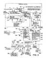
- FIG. 1is a block diagram of one embodiment of a system employing the teachings of the invention.
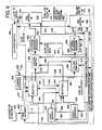
- FIG. 2is a block diagram of an alternative embodiment of a system within the genus of the invention having a pull multiplexer at the headend and a gateway at every subscriber which can receive requested video programs and/or services via a downstream HFC medium or from DSL or satellite dish inputs coupled directly to the gateway.
- FIG. 3is a block diagram of an alternative embodiment according to the teachings of the invention wherein the pull multiplexer at the headend delivers requested video-on-demand programs and services via DSL connections to the individual subscribers.
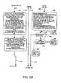
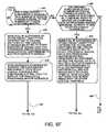
- FIGS. 5A through 5Gare a flow diagram of an optional process carried out in the gateway to optimize assembly of the output data streams for transmission to customers so that the most requests from the most customers can be honored given the number of tuners each customer has.
- FIG. 6is a block diagram of a preferred form of DSL head end cherry picker multiplexer.
- the genus of the inventionincludes all species of system architectures and methods of operation that have the following characteristics. They will include a head end multiplexer that receives upstream program and/or service requests and picks out data from input streams that satisfies those program/service requests. These head end multiplexers will output data streams for downstream transmission that satisfy those requests, and, if necessary adjust the bandwidth of the output data streams to fit the available bandwidth. The head end multiplexer will also send downstream messages to the modems or gateways at each customer premises indicating on which channels they can find their requested programs.
- the head end multiplexerculls out data packets of popular programs that are frequently watched such as CNN or ESPN and mixes that data in with data packets of requested programs on the output stream regardless of whether there has been any specific request for the high demand programs/services.
- the head end multiplexeralso does load management to maximize the efficiency with which requested programs are received and the available channels and program slots are used. For example, if it is known that three requests for three different services or programs have been received from a customer that has only one tuner, the management process will instruct the culling or cherrypicker switches to pick out the packets for these programs and/or services and put them all on the same channel where possible. If necessary, if one of the programs/services is already being transmitted on another channel and there is no room left on that channel for the remaining programs/services requested by a particular customer, then copies of the packets encoding the program/service already being transmitted will be transmitted on another channel that has room for the remaining programs/services requested by the customer.
- the head end multiplexeralso does bandwidth management in environments where available bandwidth is limited and shared between all users. Such environments include typical cable TV plants today.
- the head end multiplexer multiplexeralso known as a “cherry picker”, manages the bandwidth of the output stream such that all requested programs are present in the output stream (assuming sufficient bandwidth is available), but their bandwidth is decreased it necessary so as to not exceed the available bandwidth on the downstream medium.
- the head end multiplexerwill include circuitry to cull out all the requested program packets from the input streams, assemble the culled packets into an output stream and adjust the bandwidth of the output stream so as to not exceed the available bandwidth of the downstream medium.
- the input streamsare MPEG compressed video streams, but the invention is not limited to video program input or MPEG compression.
- the input streammay be any form of data, even uncompressed data, including IP packets or packets re-assembled from T1 timeslots or other high bandwidth telephony services. If uncompressed data is received, the cherry picker compresses it down to the available bandwidth on the downstream.
- FIG. 1there is shown a block diagram of a system according to the teachings of the invention.
- a head end multiplexer or cherry picker 10receives one or more input data streams of any type data.
- FIG. 4shows a typical head end cherrypicker structure.
- FIGS. 1 and 4there are shown are several video input streams 14 , 16 from local video and/or multimedia servers, a downlink dish etc.
- the structure and operation of the video and multimedia serversmay be any known design including the design taught in U.S. Pat. No. 5,802,283 for a multimedia server for an ADSL network, which is hereby incorporated by reference.
- the cherry picker 10also has an input coupled to any upstream medium 12 for receiving upstream program and/or service requests from the users in the customer premises.
- This inputis coupled to the receiver section 13 of a modem coupled to the downstream in cases where the downstream and upstream are transmitted on the same media or to a separate gateway, receiver or modem where the upstream 12 is a separate medium such as a telephone line etc.
- the upstream requestsidentify the requested program and/or services various users coupled to the system desired to view and/or use.
- the gateway 13controls the upstream session via a log-in procedure, authenticates the requester and her privileges, and validates the requested services and/or programs based upon the status as an authorized subscriber and whether or not the request is within the privileges of that subscriber. Valid requests from authorized users are passed on to a PC motherboard 27 of cherry picker 10 .
- the gateway 13may also send data downstream to present a menu to users of video programs, multimedia files, telephony services or wideband internet access or other wideband services which are available for selection by the user.
- the gateway 13When a valid upstream request for a program and/or service is received by the gateway 13 , it transmits a message to the appropriate server requesting that a video program and/or service(s) identified in the message be transmitted to the cherrypicker 10 via the appropriate one of the links 14 , 15 , 16 and/or 17 .
- the requestsare also passed to the PC motherboard 27 of the cherrypicker in FIG. 4 .
- the cherry picker 10converts these requests for programs and services to program identifier codes (PIDs), IP sources addresses or other identifying codes that can be used to cull out the data packets in the input streams that encode the requested programs and/or services supplied by the video/multimedia server, the T1 interface circuitry, the internet server and/or any dish interface circuitry or other interface to a source of data to which the request was passed.
- PIDsprogram identifier codes
- IP sources addresses or other identifying codesthat can be used to cull out the data packets in the input streams that encode the requested programs and/or services supplied by the video/multimedia server, the T1 interface circuitry, the internet server and/or any dish interface circuitry or other interface to a source of data to which the request was passed.
- the upstream medium 12can be any medium that can get the program and/or service requests to the cherry picker. It can be a telephone link, a satellite uplink, a microwave or radio link or it can be an upstream management and control channel that is time division, frequency division or code division multiplexed or otherwise kept separate from the downstream channels on a downstream medium 26 such as hybrid fiber coax (HFC).
- the cherry pickermust have suitable known internal or external circuitry such as a modem, receiver etc. that can interface to the upstream medium and recover the program/service requests therefrom.
- the cherry picker 10can have built into it or separate, a cable modem with a receiver section 13 that recovers the upstream program/service requests.
- Suitable cable modemsare commercially available including the Terayon TeraPro and DOCSIS modems as well as those of other manufacturers. Suitable cable modems are described in U.S. Pat. Nos. 5,768,269 and 5,793,759 which are hereby incorporated by reference.
- the cherry picker 10also includes cherrypicker switch circuitry such as are shown at 28 , 32 and 19 for generation of three output streams. There are as many switch circuits as there are output streams or channels to be transmitted. Each channel carries multiple programs/services, typically from four to twelve.
- the switch circuits 28 , 32 and 19receive upstream program/service requests on bus 21 from a management process program 23 in execution on a microprocessor 25 on a motherboard 27 .
- the motherboardhas an input 29 coupled to the data output of the upstream receiver/modem 13 to receive the upstream program/service requests extracted by the receiver 13 from the upstream data on medium 12 .
- the cherry picker switchesin the embodiment shown, also include inputs 31 through 45 for receiving raw data streams from the inputs.
- These inputs 31 through 45are coupled to the raw data inputs 14 , 15 , 16 and 17 through a plurality of passive splitters 47 , 49 and 51 . These splitters just take each input stream and couple the data onto a plurality of output streams that are coupled to the input of the cherrypicker switches.
- Each cherrypicker switch 28 , 32 and 19functions to use the program identifier codes, IP source addresses or other identifying information on bus 21 generated from the upstream program/service requests to cull out the data packets from the input streams 31 through 45 that encode the requested programs/services.
- this culling processis done by switching circuits that receive the PIDs or other identifying information from a management process 23 running on a PC motherboard 27 or other computer coupled to the upstream receiver.
- Each input streamis comprised of MPEG or other packets that have headers.
- MPEG packets that encode video, audio and associated data of programs that can be watched on a TVcontain program identifier codes. These PIDs map to the more informative long name such as CNN, Starz, ESPN, etc.
- IP packetscalled datagrams
- IP datagram headersinclude fields such as: the source IP address, an identification field that allows the destination host to determine which datagram an newly arrived fragment belongs to (all fragments of a datagram include the same ID), a fragment offset that tells where in the overall datagram each fragment belongs, and an options field that can be used for source routing information, service identification, security or anything else not thought of in the original standard. These header fields are used to determine which IP datagrams or fragments to cull out of the input stream. Likewise, telephony packets assembled from fragments delivered in T1 timeslots etc.
- the PIDs and other identifying information in each headerare examined by the cherrypicker switches and compared to the list of PIDs or other identifying information identifying the requested program(s) and/or services and/or the programs/services to be pulled regardless of requests.
- the culled packets selected by the recoder circuitshave the headers stripped and the payload data in the packets is then decompressed and recompressed if necessary to reduce the bandwidth. This process is done by the recoding circuits 53 , 55 and 57 . These circuits receive the compressed or uncompressed data packets (or a combination of the two) on input lines 59 , 61 , 63 etc. and available bandwidth information from the management process 23 on bus 65 from the motherboard 27 .
- Separate busesare shown coupling the motherboard to multiple circuits, but in reality, all these buses may be simply the motherboard-host bus and the data described herein just sent to each circuit when that circuit is addressed by the address lines on the bus.
- the available bandwidth information on bus 65tells the recoding circuits how much additional compression to perform or that sufficient bandwidth is available on the downstream to meet the current bandwidth consumption in some embodiments.
- the available bandwidth information on bus 65just tells the recoder circuits how much bandwidth is available on the downstream.
- the recoder circuitsdecide for themselves how much bandwidth is consumed by the input streams and how much compression to perform to meet the bandwidth restrictions apparent from the information on bus 65 .
- the recoding circuitsare known and commercially available from Terayon Communications Systems, Inc. in Santa Clara, Calif. They were orginally designed by Imedia Corporation and are described in U.S. Pat. Nos. 5,956,088 and 5,877,812 and 5,862,140 all of which are hereby incorporated by reference.
- the recoder circuitsoutput their compressed data to either the downstream transmitters 69 , 71 , 73 or to the motherboard 27 depending upon whether the recoder circuits include circuitry to repacketize the compressed data.
- the recoder circuitsinclude circuitry to repacketize the compressed data into MPEG or IP or other packets for the downstream
- the repacketized data for each of three channelsis output on buses 75 , 77 and 79 , respectively to the three transmitters 69 , 71 and 73 for these three channels.
- the recompressed datais output on a bus 81 to the motherboard for repacketization there. These embodiments are symbolized by bus 81 in dashed lines.
- the repacketized datais transmitted via bus 83 to the transmitters 69 , 71 and 73 for downstream transmission as appropriate.
- Each downstream transmittermodulates the output data onto a different frequency carrier for coupling to the downstream medium in the preferred embodiment.
- the transmittersmultiplex the data of the different channels into different logical channels on the downstream by any known form of multiplexing.
- the downstream multiplexingcan be FDMA, TDMA, SCDMA, CDMA, STDMA, DMT or, in the case of fiber optic media transmissions at baseband, simply a digital burst of packets transmitted in assigned minislots for each transmitter and with programs and services separated at the destination host by the PIDs or other identifying information in the packet headers).
- the switching circuits 15 , 17 , 19 etc.simply cull out the data packets of the requested program and/or services and send them to the downstream transmitters for driving onto the fiber without bandwidth alteration.
- the video streams output by the cherrypicker switchesare sent to the PC motherboard 27 for changing of PIDs or addition of other information to packet headers.
- the PC motherboardis programmed to repacketize the culled, recoded data from the recoder circuits 53 , 55 and 57 into downstream packets and assemble the packets into one or more output streams on bus 83 (only in embodiments where recoding and repacketization is necessary).
- the PC motherboard(it could be a Macintosh motherboard or Unix motherboard also) also, optionally, performs a load management process to get all requested programs from any particular customer onto the number of channels that customer's equipment is capable of tuning.
- This processis done by outputting the PIDs or other information by which to do the culling process on bus 21 such that the cherrypicker switches are controlled to put all the PID data from requested programs from one customer onto the number of channels that customer is capable of simultaneously tuning. If the customer's modem or gateway can only tune one channel at a time, all the PIDs for the requested programs/services are sent to one cherrypicker switch so they will all appear on one downstream channel. The load management process then generates a downstream message addressed to that customer telling the customer upon which channel the requested programs/services will appear. If the customer can tune three simultaneous channels, the requested programs and/or services can be put on three different channels if necessary, and the appropriate downstream messages are generated by the motherboard and sent downstream. The downstream messages are sent from the motherboard 27 to the downstream transmitters via bus 83 .
- Each transmitter or modulatormodulates the data of its output stream into a downstream channel that is typically 6 Mhz wide.
- Conventional transmitter/modulator circuits suitable for the downstream medium in usecan be used.
- all the transmitters/modulatorscan be a single SCDMA cable modem such as are commercially available from Terayon under the TerraPro trademark and described in U.S. Pat. Nos. 5,768,269 and 5,793,759.
- These modemscan accepts TDMA input streams having multiple logical channels each one of which is one of the output streams from the cherry picker 10 and modulate each output stream onto a separate logical channel or program slot of a single 6 Mhz QAM modulated RF carrier.
- Each customer premiseshas a gateway and/or cable modem coupled to the downstream medium such as are illustrated at 28 and 30 .
- the function of these gateways and cable modemsis to receive the digital data of the requested programs/services and route it over a local area network in the customer premises to the settop decoder or other peripheral that requested the program/service.
- An exemplary gateway that can serve the functions of gateways 28 and 30is taught in U.S. patent application entitled HOME NETWORK FOR ORDERING AND DELIVERY OF VIDEO ON DEMAND, TELEPHONE AND OTHER DIGITAL SERVICES having Ser. No. 09/483,681, filed Jan. 14, 2000, which is hereby incorporated by reference.
- Incoming packets for a video program that have been requested via settop decoder 18are encapsulated into an Ethernet or other LAN packet (depending upon the LAN 9 in use and sometimes hereafter referred to as simply Ethernet packets for brevity) and routed to the appropriate settop decoder that requested the program such as settop decoder (sometimes the IP packet header information is stripped and in other embodiments it is not but the PIDs or other program information is not stripped). If multiple requests have been made from different settop decoders in the same household, the LAN packets for the different programs requested are addressed to the settop decoders that requested each particular program.
- the payload data on all the program slots dedicated to this video programsuch as the audio and video data is decompressed back to its original resolution and converted to a signal format on line 116 suitable for television 100 .
- TV 100is an NTSC, PAL or SECAM TV
- the appropriate analog signal formatsuch as an NTSC signal modulated onto RF channel 3 or 4 is generated.
- the settop decoderis coupled to the video or S-video and audio inputs of the TV that bypass the tuner, the video and audio data is converted into analog composite video and audio signals on line 116 .
- each TVwill have an Intelligent remote control such as is shown at 102 and 104 .
- Each of these remoteshas a bidirectional radio frequency or infrared link to the settop decoder, and each of these remotes has a miniature display thereon upon which digital data associated with a program may be displayed either with or without simultaneous display on the data shown on the TV. For example, if a user is watching Goldeneye on TV 100 suppose there is associated digital data with this video program for home shopping when 007's car is in the scene such “BMW Z3 Roadster available locally from Acme BMW, phone number (408) 555-1212”. This message can be displayed on the minidisplay on the remote only or both on the minidisplay on the remote and on the TV also.
- the customer premises gateway or cable or ADSL modem in each customer premisesis also coupled to other peripherals in the household such as computers or telephones or FAXes or digital VCRs or network computing devices (no local hard drive) via one or more local area networks.
- LAN 9 in customer #1's housecouples gateway 28 to a digital phone 108 and a PC or Mac personal computer 110 .
- a second LAN 11couples gateway 28 to FAX 452 and another personal computer 454 .
- the second LAN 11may have a different medium type, use a different protocol or be of higher bandwidth than the first LAN as long as the gateway 28 has the appropriate network interface circuitry to interface to said second LAN.
- Each gateway at a customer premisesalso may have inputs for and appropriate interface circuitry to receive broadcast data and other digital services such as DirectPC data from a satellite dish 456 , a terrestial broadcast TV antenna 458 , the public service telephone service network 460 or a DSL line 462 .
- the gateway 28includes circuitry to interface to each one of these signal sources, recover digital data from the source or digitize incoming analog signals, compress the data if necessary because of bandwidth availability conditions on the local area networks, encapsulate the data into IP packets and then into LAN packets and route the packets to the peripheral that requested the program/service.
- Upstream data from the peripheralswill be received by the gateway from the LANs, the Ethernet packet headers will be stripped off and the IP packets routed to the appropriate interface circuitry interfacing the gateway to the appropriate upstream data path (which will depend upon the downstream medium upon which the downstream data arrived). For example, if DirectPC IP packets are received from the satellite dish, any upstream IP data packets will be routed to a conventional modem circuit in gateway 28 coupled to PSTN 460 . Likewise, if downstream IP packets were received from the DSL line, upstream packets will be routed to a DSL modem in gateway 28 coupled to the DSL line for upstream transmission on the upstream DSL channel. If downstream IP packets are received from downstream medium 26 and it is hybrid fiber coax (HFC), upstream packets will be routed to a cable modem in gateway 28 which has an output coupled to the HFC for transmission on the upstream logical channel.
- HFChybrid fiber coax
- wideband internet access IP packetswill be encapsulated into Ethernet packets by gateway or cable/DSL modem 28 and addressed to the PC 110 or PC 452 .
- the network interface card (not shown) of PC 110 or PC 452receives the Ethernet packets and strips off the Ethernet headers and passes the IP packets up through the IP protocol stack to the application that requested them. If the application has IP packets to send back out to the internet through the headend, the packets are generated in the application and sent down to the network interface card.
- the NICencapsulates them into Ethernet packets and transmits them to gateway or cable/DSL modem 28 .
- the gateway/modem 28then takes these packets and transmits them to the headend via data path 118 and whatever upstream data path 12 is being used using whatever form of multiplexing and modulation is being used. For example, if gateway/modem 28 is a cable modem and the upstream data path 12 is hybrid fiber coax, then the IP packets are disassembled and interleaved, Trellis encoded, code division multiplexed onto whatever logical channels are assigned to cable modem 28 and QAM modulated onto the RF carrier being used to frequency division multiplex the upstream data from the downstream data.
- a cable modemreceives the upstream signals from cable modem 28 and recovers the IP packets in conventional manner and routs the IP packets out to the internet over data path 15 to a server or router at the headend coupled to the internet.
- the serveris a file management system which functions to receive input video and/or multimedia or other files from providers, store these files with descriptor information about them, keep track of sessions, serve the data files out on links to the cherrypicker, and handle requests for files from the cherrypicker motherboard.
- IP packetsare culled out of the stream of packets on line 17 by cherrypicker 10 and output in the output stream devoted to the channel and program slot to which telephone 10 B has been assigned for a particular session. The IP packets are then transmitted downstream to gateway 28 by whatever transmitter and downstream media 26 is in use.
- the IP packets addressed to telephone 108are recovered and encapsulated into Ethernet or other LAN packets addressed to telephone 108 .
- the Ethernet packetsare received and the encapsulated IP packets are recovered and the payload data is converted to analog signals for use by the telephone.
- Analog signals generated by telephone for transmission out on the T1 lineare then digitized and encapsulated into IP packets addressed to the T1 line interface circuitry (not shown) coupled to the cherrypicker 10 .
- the telephone 108may a video conferencing or other high bandwidth device needing T1 bandwidth.
- the outgoing digital data from the telephone 108 or video phone or video teleconferencing apparatus also represented by 108is then encapsulated into IP packets addressed to the T1 line interface circuitry coupled to the cherrypicker 10 at the headend. These IP packets are then encapsulated into Ethernet or other LAN packets addressed to the gateway/modem 28 and transmitted over the LAN to gateway/modem 28 where they are received and the IP packets recovered. The IP packets are then transmitted upstream to the cherrypicker 10 via data path 118 using whatever form of multiplexing and modulation that is conventional for the upstream path 12 .
- upstream multiplexingsuch as SCDMA, CDMA, FDMA or TDMA is used to separate the upstream data from the various customers.
- upstream datamust be multplexed to keep it separate from the downstream data.
- FDMAis used for that purpose but other forms of multiplexing could also be used.
- the upstream IP packets for telephony and wideband internet accessare recovered by conventional upstream receiver/modem/gateway 13 .
- the IP packetsare then transferred to the PC motherboard 27 where a routing process examines the IP destination addresses and routs each packet onto the appropriate one of the lines represented by bus 120 .
- This buscontains individual lines coupled to the T1 interface circuitry via data path 17 and to the server, router or gateway circuitry (not shown) coupled to the Internet and coupled to the cherrypicker 10 via data path 15 in some embodiments, and, in other embodiments, is a packet data network sharing a single transmission medium to which both the T1 interface circuitry (not shown) and the internet server, gateway or router (not shown) are connected by network interface cards.
- IP packets to be sent out over the internetare routed by PC motherboard 27 onto line 122 and IP packets to be transmitted on the T1 line are routed onto line 124 .
- These lines 122 , 124symbolize either separate physical data paths to the wide area network server(s) and telephone company digital switches or separate upstream logical channels transmitted to these servers on the same medium upon which downstream IP packets and telephony packets were transmitted to the cherry picker 10 .
- LAN 106connects a gateway 30 to two different settop decoders 22 and 24 each of which converts the video and audio packets of requested programs into video and audio analog signals on lines 112 and 114 , respectively.
- Either the remotes 102 or 104 or the settop decoders 18 , 20 , 22 or 24can be used to enter video-on-demand program requests. If the remotes are used to enter program requests, the identifying information is transmitted by an RF or infrared link to the settop decoder associated with the remote. These RF and IR links are symbolized by dashed lines 126 and 128 in FIG. 1 .
- Service requestsare generated by one or more telephones and/or personal computers and/or other peripherals at each customer premises. Each service request is encapsulated into an Ethernet (or other LAN) packet which may be addressed to the gateway/modem 28 , 30 etc. or, in alternative embodiments, to the settop decoder circuits 18 , 20 , 22 or 24 .
- program and service requestsare transmitted from the gateway/modem or settop decoder to the headend cherry picker via data paths 118 or 130 or 132 or 134 or 136 or 138 , as appropriate.
- headend cherrypicker upstream receiver/modem 13 in FIG. 4recovers the program and service requests and passes them on to the PC motherboard 27 . There they are processed and the PIDs and source addresses in IP packets to be culled out and put into the various output streams on lines 75 , 77 and 79 are derived and relayed to the culling switches 15 , 17 , 19 etc.
- the video program and service requestscan be sent as long program names and then converted at the headend PC motherboard into PIDs and/or IP source addresses or other identifying information by a table lookup process.
- the PIDs and/or IP source addresses or other identifying information to be used by the culling switches to pull out the desired programs and servicesare sent to those switches via bus 21 .
- PIDprogram identifier code
- IP source addressesany other identifier of the program or service the data encodes.
- PIDsthe PIDs mapped to the requested program(s) will be in the MPEG packets of the video, audio and any associated data packets of the desired program(s) in the input video streams on lines 14 , 16 etc.
- other types of servicessuch as high speed internet access, telephony over CATV cable plants, or fiber-to-the-curb plants, etc.
- This mapping functioncan be done at the cherry picker 10 or, alternatively, it can be done at the settop decoder boxes such as are shown at 18 , 20 , 22 and 24 such that the upstream program requests are already in the form of the PID(s) that identify all the components of the desired program.
- PIDswill be in the MPEG packets of the video, audio and any associated data packets of the desired program(s) in the input video streams on lines 14 , 16 etc.
- These PIDsare what the cherry picker 10 uses to cull out all the MPEG data packets of the requested programs from the input streams 14 , 16 etc.
- circuitrysuch as a gateway to route valid requests for video programs and/or services to the appropriate servers to cause them to transmit the data of the video program or service to the culling switches.
- the culled datais packetized into MPEG or other compression format packets after having been bandwidth adjusted if necessary and grouped into one or more output streams 208 , 210 and 212 , each output stream having packets for multiple programs and/or services therein.
- Each output streamis supplied as a data input to one cable modem in a bank of cable modems 204 .
- Each cable modemmultiplexes the data from the different programs and services in the input stream into different logical channels by any known form of multiplexing such as frequency division, code division or synchronous code division, time division or synchronous time division, discrete multitone etc.
- the different logical channelsare each then modulated onto one or more carriers that are frequency division multiplexed from each other and from the upstream data by any known form of modulation such as by quadrature amplitude modulation, QPSK etc.
- the downstream messagesare typically transmitted on one or more logical channels dedicated to management and control traffic or they may be transmitted on a subchannel or by any other out-of-band or in-band scheme known in networks for transmitting management and control data. If the downstream messages are broadcast, the individual gateways at each customer premises compares the PIDs and/or other identifying information in the broadcasts with the PIDs and/or other identifying information of the programs and services that were requested to find the carrier and logical channel on which the requested data will be arriving.
- gateways and cable modems at the customer premisessuch as gateway 214 and cable modem 216 are similar to the gateways and cable modems previously described in FIG. 1 .
- Incoming MPEG and IP packets for requested programs and servicesis recovered from the carriers and logical channels indicated in the downstream messages.
- the Ethernet addresses of the peripherals that requested each program and serviceis then looked up based upon the PID and/or IP source address or other identifying information in each incoming MPEG and/or IP or other format packet.
- the peripheralsWhen the peripherals generate their program and/or service requests, they are encapsulated into Ethernet packets and transmitted to the gateway or cable modem. Each request is recorded in a table that contains entries to identify the program/service requested and the Ethernet address of the requesting peripheral.
- Incoming packets from the headendusually only have PIDs and/or IP source and destination addresses but they may also have other identifying information.
- the gateway 214 and cable modem 216maintain a mapping table at least between the PIDs and IP addresses or other identifying information of all programs and/or services requested and the information such as the long name or menu number identifying that program or service received from the peripheral.
- This tablecan be stored in nonvolatile memory such as ROM if the mappings do not change or may be built in RAM at powerup time by a request to the headend to download the current mapping table.
- any known way of figuring out to which peripheral the data packets for each requested program and/or service are supposed to be addressedwill suffice for purposes of practicing the invention will suffice.
- the recovered packetsare encapsulated into Ethernet or other LAN packets. These LAN packets are addressed to the peripheral that requested them and driven onto the LANs 218 and 220 .
- the gatewaysmay be coupled to the peripherals by individual dedicated coaxial cables, twisted pairs, Cat 5 wires, phone lines or power lines or a wireless connection using various technologies currently available.
- lines 694 , 696 , 698 and 700may represent Home PNA telephone line networks which may have only one (or more) peripherals attached thereto, or Category 5 LAN droplines with only one (or more) peripherals attached thereto, or power line networks each having one or more peripherals attached thereto offered by Inari or Itran or Intellon to save the expense of rewiring the home to add a network.
- connection from the gateway to each peripheralmay be by a wireless network such as those offered by Blue Tooth or specified in the 802.11 standard.
- the drop lines 694 etc.may each be a separate, dedicated coaxial line or twisted pair.
- the gateways 20 and 30 in FIGS. 1 and 214 in FIGS. 2 and 308 in FIG. 3will each have a plurality of individual line driver modules which can be coupled to the gateway backplane. Each module is designed to drive a different type of network connection or dedicated line. All these line driver modules receive IP packets from the routing process in accordance with whatever peripherals are coupled to each line and drive them onto the particular type of media the driver is designed to drive using whatever protocol the particular line requires.
- Line driver circuits for each of the dedicated and shared media types identified aboveare known.
- Driver modules for indivual coaxial cables that were previously installed in a home to distribute CATV signalssimply include multiplexers to transmit FDMA separated upstream and downstream logical channels in the bandwidth not used by the analog CATV signal.
- the peripheralsmay include, but are not limited to settop decoders 220 and 222 , digital phones 224 and 226 , digital VCR 228 , and personal computer 230 .
- Upstream requests for programs and services and upstream data such as IP packets from these peripheralsare encapsulated into Ethernet packets and sent to gateway 214 and cable modem 216 . There, the Ethernet headers are stripped and the requests and upstream data are transmitted on HFC 200 on the upstream logical channel(s) that are devoted to upstream traffic.
- the cable modems in cable modem bank 204recover the upstream requests and data and transmit it over data path 206 to a computer 232 in the pull multiplexer.
- the requestsare routed to the culling switches in all embodiments and to the servers that supply the raw input data in some embodiments.
- the upstream datais routed to the appropriate telephony interface circuitry or internet server/gateway/router for transmission to the host or device on the other side of the transaction.
- FIG. 3there is shown a DSL embodiment of a system that employs a DSL headend multiplexer within the genus of the invention.
- FIG. 6is a block diagram showing more detail of a DSL multiplexer that can be used as the headend cherrypicker in the DSL environment. The reader should refer jointly to FIGS. 3 and 6 for the following discussion. Operation of this embodiment is similar to that of FIG. 2 except that the downstream and upstream medium to each customer premises is a DSL telephone line so there is no sharing of the upstream and downstream medium by data bound for different customers.
- Each customerhas a DSL modem such as 242 and 244 which couples the DSL line to an Ethernet or other local area network such as 246 and 248 coupled to all the peripherals at the customer premises.
- the peripheralscan include but are not limited to settop decoders 250 , 252 and 254 , phones 256 and 258 , digital VCR 260 , FAX 261 , personal computer 262 or network computing appliances and can include household appliances that are internet ready for remote service calls and diagnosis or remote control.
- Some of the peripheralsgenerates upstream requests for programs and/or services, and can generate them in any way.
- upstream requests for programs and servicesare generated by selection from a menu displayed on the peripheral such as a television coupled to a settop decoder.
- the menusare generated on the TV screen, computer screen, phone or FAX display from downstream menu data transmitted on a management and control channel of the DSL line to each customer premises, said downstream menu data encoding all available programs and/or services.
- Each peripheralmay also generate upstream data for transmission out on a wide area network 600 or a T1 line 602 or other wideband data delivery network.
- conventional analog telephones(not shown) can be connected to POTS outputs of the DSL modems at each customer premises, and they can generate upstream analog POTS signals which are transmitted over the POTS baseband channel of the DSL line to the DSL modem at the headend.
- the POTS analog signalsare recovered and output at POTS outputs.
- Each POTS output of a DSL modemis coupled by a bidirectional tip and ring pair such as 604 for customer #1 and 606 for customer # 2 to a CO POTS switch 608 .
- video phone 258 and digital FAX 261 coupled to the LAN at each customer premisescan generate digital telephony data such as video conference pictures and audio that needs to be transmitted upstream for routing to the WAN server or T1 interface circuitry at the headend or via a satellite uplink via dish 340 and dish transceiver 342 for delivery to the destination.
- other peripherals coupled to a customer LANsuch as personal computers 262 and may also generate upstream data that needs to be delivered to its destination by WAN 600 or T1 line 602 or a dish uplink or via PSTN interface circuitry 319 and a conventional telephone line such by a DirectPC PSTN upstream link.
- the requests and upstream telephony and other dataare transmitted to the customer gateways or DSL modems as Ethernet or other LAN packets.
- the gateway or its internal DSL modem 244strips off the Ethernet headers and CRC bits after error correction and transmits the requests and data to the appropriate place.
- All requests for programs/servicesare transmitted upstream either via the DSL line 310 to the DSL central office or on the upstream logical channel of the HFC 316 .
- All upstream data that needs to be delivered to its destination via WAN 600 or T1 line 602is transmitted upstream via DSL modem 244 or upstream to the CATV headend via cable modem 318 .
- All upstream data that will be delivered to its destination by a satellite uplink or a PSTN connectionis delivered to the proper interface circuit in gateway 308 such as dish transceiver 342 or PSTN interface 319 .
- requests for programs/servicesare transmitted on a management and control channel on an upstream logical channel transmitted on a carrier of a bidirectional channel that is frequency division multiplexed from the DSL baseband POTS telephony channel and the DSL wideband downstream only logical channel.
- Bidirectional IP packet and telephony datasuch as video conference data and Internet access data is transmitted both upstream and downstream on upstream and downstream logical channels of the bidirectional channel, or, in alternative embodiments, may be transmitted on upstream and downstream logical channels of the 1.544 Mbps wideband DSL channel.
- downstream only wideband datasuch as video-on-demand and other services are transmitted in the 1.544 Mbps wideband downstream only DSL channel, or, in alternative embodiments, in a separate downstream logical channels on 1.544 Mbps wideband data channel that is FDMA multiplexed from the other channels.
- the DSL modems at the customer premises and the head endeach transmit and receive telephony, IP packet, management and control data, video-on-demand data and other service data on separate logical channels on the appropriate carriers and channels as described above.
- a DSL modem such as 270 and 272 at the headendis devoted to each DSL line to a particular customer.
- Each DSL modem at the headendhas a conventional structure.
- DSL modemsare commercially available from 3COM.
- Each DSL modem at the headend and the customer premisesfunctions to send and receive information on three channels: a separate analog channel for “plain old telephone service” (referred to herein as POTS); a high speed wideband downstream channel based upon T1 specifications in increments of 1.536 Mbps up to 6.144 Mbps (referred to herein as the wideband channel); and, a bidirectional channel provided in increments of 64 Kbps up to 640 Kbps (referred to herein as the bidirectional channel and which carries requestes and upstream data in the preferred embodiment).
- POTSplain old telephone service
- the wideband channela bidirectional channel provided in increments of 64 Kbps up to 640 Kbps
- the bidirectional channeland which carries requestes and upstream data in the preferred embodiment.
- telephony data packetsarrive on line 17 from the T1 interface circuitry 610 (T1 interface chipsets are commercially available).
- analog telephony signals generated from “plain old telephone service”arrive from a central office POTS switch 608 on line 304 in FIG. 3 which corresponds to each customer's tip and ring pair in FIG. 6 , of which pairs 604 and 606 in FIG. 6 are typical.
- POTSplain old telephone service
- Digital telephony packetsreach the DSL modems a different way.
- the pull multiplexer 240 in the central office 239culls out digital telephony packets addressed to each separate telephone number using culling information on lines 614 and 616 .
- This culling informationis generated by control computer 618 from upstream program/service requests received on lines 620 and 622 from the DSL modems 270 and 272 .
- the requests on line 620are customer #1's requests, and line 622 carries customer #2's requests.
- the DSL modemsrecover these requests from the bidirectional upstream channels of DSL lines 312 and 310 of customers #1 and #2, respectively.
- the headend cherrypicker 240routes the telephony data packets to the appropriate DSL modems 272 , 270 , etc. This routing may be by way of a separate data path to the DSL modem (not shown) or over buses 305 . In the preferred embodiment, the telephony packets are simply put on a separate logical channel (separated from the video and other service packets by header information) in the input data stream to the DSL modems.
- the slash marks in these linessymbolize embodiments that have three separate inputs to each headend DSL modem: one for POTS telephony, one for downstream management and control data and downstream IP data and other data not requiring high bandwidth; and one for high bandwidth downstream data such as requested video-on-demand programs and services or pushed programs and/or services.
- the headend DSL modemshave a single digital data input
- the telephony packets, IP packets and video-on-demand packets and other service packets in the input stream from the cherrypicker 240are culled out in the modem by information in the headers in accordance with management and control messages received from the cherrypicker. These management and control messages tell the DSL modem which channel and logical subchannel to use to transmit each packet.
- These management and control messagesare sent to the DSL modems from the control computer 618 via the data paths 626 and 628 in FIG. 6 .
- the DSL modemsuse those control messages for two functions. First, these messages are used to control the DSL modem modulators to get the requested and pushed programs on the logical channels and subchannels specified in the message. Second, these messages are sent to each customer on the bidirectional channel to tell the customer gateway or DSL modem on which channels and subchannels it can find the requested and pushed data so the gateway or DSL modem can properly tune its tuners to recover the requested and pushed data.
- Upstream telephony, request data and other upstream data from the telephones and other peripherals at the customer premisesare encapsulated into Ethernet packets and addressed to a DSL modem or gateway.
- the upstream data on the LANis addressed to DSL modem 242
- the upstream datais addressed to the gateway 308 .
- the gateway 308routes the telephony packets and upstream request data and other data to be transmitted to the headend to an internal DSL modem 244 .
- the DSL modem 244transmits the upstream data and telephony packets on the bidirectional channel (or an upstream logical channel in the broadband channel in some embodiments).
- Analog POTS signals from any conventional telephones 630 and 632 coupled to the DSL modems 244 and 242are transmitted upstream as analog voice and POTS call control and call progress signals on the baseband POTS channel.
- the analog voice and call control POTS signalsare recovered and transmitted on the appropriate tip and ring pair, e.g., 606 and 604 for customers #1 and #2, to the CO POTS switch 608 .
- Upstream request data and other upstream datasuch as IP packets are recovered by the DSL modem of each customer from the bidirectional channel or logical upstream channel of the broadband channel and sent to the control computer 618 via data paths 620 and 622 for customers #1 and 2, respectively.
- the control computer 618then routes these upstream data packets either to the T1 telephony interface circuitry 638 via line data path 636 or WAN gateway/router/server 640 via data path 642 .
- the DSL modems 272 , 270 , 242 and 244send and receive upstream and downstream management and control packets on the bidirectional channels of DSL lines 310 and 312 .
- the management and control channelsare transmitted on a carrier centered on 95 MHz which provides 8 Kbps of bandwidth for management and control messages and handshaking protocol between the subscriber and CO.
- This carrier of the bidirectional channelis used to test the copper pair transmission path and to provide approximately 16 Kbps of upstream D-channel bandwidth from the subscriber premises to the CO for request messages and upstream data such as IP packets, video conferencing data, etc.
- the 1.544 Mbps broadband channelis bidirectional and the upstream and downstream data are multiplexed into separate logical channels by TDMA, FDMA, CDMA or DMT.
- the D-channelis bidirectional and reserved for upstream data that can be sent within its bandwidth and higher bandwidth upstream traffic like video conference data of higher quality is multiplexed onto an upstream logical channel of the broadband channel with the downstream logical channel carrying compressed video and and downstream IP packets of requested and pushed video programs and services.
- the high bandwidth data of downstream requested programs and services and pushed programs and servicesis modulated onto the broadband 1.544 Mbps channel extending from 100 to 500 Khz.
- the high bandwidth channeltypically carries downstream only (CO to subscriber) digital data and provides 1.544 Mbps transport (1.6 mbps with overhead) for carrying digitized compressed video data and IP packets.
- the lower edge of the high bandwidth channelis set at 120 Khz, which is chosen to minimize channel loss and allow appropriate bandwidth for the baseband telephony channel and the bidirectional channel. This minimizes interference from impulse noise.
- the combined digital downstream signalutilizes the DS1 bit map specified by ANSIT 1.403-1989.
- high bandwidth upstream trafficcan also be multiplexed thereon. There is no need for multiplexing if data transmission is unidirectional downstream on the high bandwidth channel since only the programs and services requested by one user are on that users DSL line. If, however, upstream video conference telephony and IP packet data is to be transmitted from the peripherals to the T1 interface circuitry 638 or the WAN server 640 on the high bandwidth channel, that data may be time division or code division multiplexed onto an upstream logical channel of the 1.544 Mbps channel.
- Gateway 308also include circuitry to interface the LAN 246 at the customer premises #2 to several other sources of incoming programming and/or data and to send data out on upstream mediums other than the DSL line such as the PSTN or a satellite uplink or an HFC connection to a CATV headend.
- the details of the gateway 308are given in the patent application HOME NETWORK FOR ORDERING AND DELIVERY OF VIDEO ON DEMAND, TELEPHONE AND OTHER DIGITAL SERVICES, filed Jan. 14, 2000, Ser. No. 09/483,681 which is hereby incorporated by reference, but some of the circuitry will be summarized here for completeness.
- the gatewaycouples a CATV headend 314 and HFC data path 316 to LAN 246 via a cable modem 318 and various other circuits in the gateway that perform necessary services and routing of data to and from the LAN 246 .
- the gatewayincludes tuner, A/D, decoder, demultiplexer and demodulation circuitry represented by block 320 which performs various functions to interface the gateway to HFC 316 .
- the HFC 316can carry downstream conventional FDMA analog video broadcasts for video conferencing or CATV delivery, digital video broadcasts and/or downstredam DOCSIS data modulated onto upstream and downstream carriers.
- the gateway 308can also request video-on-demand, video conferencing, wideband internet access or other services via the upstream logical channel on the HFC 316 as an alternative to DSL delivery.
- the gateway 308has a tuner for each downstream carrier on the HFC, all of which are symbolized by block 320 .
- the analog video tuner(not separately shown) tunes to whatever analog CATV video channel or video conferencing channel which has been requested and outputs an RF signal which is then digitized and demodulated to a baseband NTSC, PAL or SECAM downstream digital video signal. This data is at too high a bandwidth to send over the LAN 246 , so the data must be compressed.
- a video decoder in block 320(not separately shown) converts the signal to YUV format and then it is compressed in an MPEG II or other encoder 322 .
- IP video circuit 324encapsulates the compressed video into IP packets addressed to the peripheral which requested the program, and the IP packets are sent to a router/network interface circuit 326 which routes the packets onto the correct LAN (there may be more than one LAN coupled to the gateway) and drives them onto the LAN media.
- a CPU 328coordinates all this activity.
- a tuneris tuned by computer 328 to the appropriate HFC video-on-demand carrier and rejects all other signals.
- the output of the tuneris then digitized and will contain digitized video and audio signals and may also contain IP packets of associated data. All this data will be on different program slots of one or more downstream channels from the CATV headend 314 .
- a QAM or other demodulator in block 320then recovers the constellation points encoding all these signals and data and a transport demultiplexer in block 320 separates the video, audio and associated data constellation points into separate streams of decoded data.
- conditional access decryptionfollows and the resulting data is usually compressed into MPEG packets by MPEG encoder 322 and encapsulated into IP packets by IP video circuit 324 and routed to the peripheral that requested it over LAN 246 via router/NIC 326 .
- the data or requested and pushed video-on-demand programs or video conference data delivered either by HFC 316 or DSL lineis received and converted into NTSC, PAL or SECAM video signals for the associated television, such as TV 329 .
- the settop decoders such as 252may have a video phone or conventional video camera 334 coupled thereto to generate the upstream portion of a video conference as conventional NTSC, PAL or SECAM format video signals with audio.
- the settop decoderincludes conventional circuitry to receive, digitize, compress and packetize upstream video and audio signals and address the packets to the router/NIC 326 in gateway 308 .
- the routersends the upstream video conference packets to the dish transceiver 342 , the cable modem 318 or the DSL modem 244 for upstream transmission via satellite uplink, HFC 316 or DSL line 310 , respectively.
- video conferencingcan be achieved using the settop decoder 252 and television 329 for downstream data and the video camera 334 and settop decoder 252 for upstream video and data transmission.
- any associated data to be used with a video-on-demand or pushed program(such as a pushed home shopping program), to be sent to, for example, a phone 644 near the TV being viewed (for home shopping transactions) or personal computer 332 , is converted to a format suitable for the personal computer or the phone.
- Both the phone 644 and the PC 332are plugged into the settop decoder 252 so as to receive the associated data so as to be able to interact with the vidoe-on-demand or pushed program being viewed for, for example, impulse buying.
- Gateway 308also includes tuner for DOCSIS data such as wideband internet access IP packets transmitted downstream on the HFC 316 , said tuner being included within cable modem 318 .
- the gateway 308can also interface the LAN 246 to a conventional TV antenna 336 .
- a tuner 338under control of CPU 328 tunes to whatever conventional broadcast channel has been requested.
- the RF output of the tuneris then digitized in an A/D converter in block 320 and demodulated by a video demodulator which is part of block 320 to generate an NTSC, PAL or SECAM baseband signal.
- a video decoderwhich is part of block 320 converts the video signal to YUV format and MPEG encoder 322 compresses the video data.
- IP video circuit 324encapsulates the output of the MPEG encoder and sends it to router/NIC 326 where it is routed to the appropriate settop decoder circuit for the TV that ordered the broadcast.
- the gateway 308can also interface the LAN 246 at customer premises # 2 to a satellite dish 340 .
- the satellite dishcan send multiple forms of signals to the gateway.
- analog video signalssuch as C-band subscription broadcast video can be received and/or digital video can be received such as DirecTV.
- digital data servicessuch as DirectPC may also be received.
- a separate tuner for each of these servicesis either part of dish receiver 342 or part of block 320 .
- the DirecTV tunerwill feed a QAM demodulator as part of block 320 which detects the actual symbols sent for each constellation point and outputs a digital stream to a transport demultiplexer which, under the guidance of CPU 328 , separates out the MPEG packets in the subchannels or program slots carrying only the programs that have been requested or pushed programs.
- the MPEG packetsare then sent through a transcoder which is part of block 320 to adjust the bandwidth of the isochronous video data to the available bandwidth on the LAN 246 for current load conditions.
- the transcoder circuitis implemented on commercially available integrated circuits which were formerly manufactured by Imedia and are now manufactured by Terayon Communications Systems, of Santa Clara, Calif., the assignee of this patent application.
- the transcoderreceives an input from the CPU 328 regarding how much compression is needed and then uncompresses the input MPEG packets and recompresses them down to the new bandwidth as new MPEG packets.
- a conditional access circuitthen authenticates the requester as a subscriber and decrypts the data so that it can be viewed.
- the decrypted MPEG packetsare then sent to IP video circuit 324 for encapsulation into IP packets and then to router/NIC 324 for routing and encapsulation into Ethernet packets and driving onto LAN 246 .
- IP video circuit 324for encapsulation into IP packets and then to router/NIC 324 for routing and encapsulation into Ethernet packets and driving onto LAN 246 .
- DirectPC signals arriving from dish 340are tuned in dish transceiver 342 under control of CPU 328 and the output is coupled to a QPSK demodulator which recovers the IP packet data of the requested service.
- the IP packetsare then sent directly to router/NIC 326 for routing and encapsulation into Ethernet packets and transmission to one of the personal computers such as 332 or a network computer (not shown).
- Analog video signalssuch as C-band broadcasts that have been requested are tuned by the dish transceiver 342 under command of the CPU 328 .
- the output RF signalis digitized and a video demodulator in circuit 320 converts it to baseband NTSC etc.
- a video decoder in circuit 320then converts the NTSC signal into YUV format for compression in MPEG encoder 322 .
- the compressed datais then sent to IP video circuit 324 for encapsulation into IP packets and from there to router/NIC 326 for routing and encapsulation into Ethernet packets and transmission over the LAN to the requesting settop decoder.
- Gateway 308 and its LAN(s) and other input devicesmay be substituted for gateway 214 in FIG. 2 and gateways 28 and 30 in FIG. 1 .
- the DSL headend multiplexer 240works the same way as the headend multiplexer 10 in FIG. 1 with regard to video-on-demand programs.
- Requests from the customers received by control computer 618are converted to PIDs and transmitted to video servers 646 and 648 via lines 650 and 652 .
- These video serversthen output the MPEG packets of the requested programs on data paths 654 and 656 from video server 1 and data paths 658 and 660 from video server 2 .
- Splitters 662 and 664copy these data streams to each of the culling switches 666 and 668 .
- the splittersalso receive input IP packets from WAN gateway 640 via path 15 and from T-carrier interface circuit 638 via data paths 17 and 672 . These IP packets are copied out to the culling switches also.
- the cullingswitches cull out the MPEG packets of the requested video and pushed video programs and the IP packets of the requested services from the data streams from the splitters on data paths 676 , 678 , 680 and 682 in accordance with culling data given to them on lines 614 and 616 from the control computer 618 .
- the culled out data packets for customer #1appear on line 684
- the culled out data packets for customer #2appear on line 686 .
- Optional bandwidth recodersthen adjust the bandwidth of the resulting data streams in accordance with commands from the control computer 61 B transmitted via lines 692 and 694 .
- the resulting output data on buses 305 and 624are transmitted downstream by the DSL modems.
- the pull multiplexerassumes that all cable modems and gateways have a sufficient number of tuners to tune in all the programs and/or services requested from a single customer premises. In such embodiments, the pull multiplexer simply gathers upstream program/service requests and culls out the packets that encode the data of the requested programs and services. These packets are then assembled into output streams for the appropriate media coupling the pull multiplexer to the requesting customer and downstream messages are sent to the customer's modem or gateway telling it on which media, channel and subchannel/program slot each requested program and/or service can be found.
- the pull multiplexerjust assembles the requested program and service packets into one or more output streams to be transmitted in a corresponding number of logical channels.
- the pull multiplexerjust puts the requested programs and/or services from a single premises into whatever subchannels or program slots are available in logical channels that are not fully utilized and sends downstream messages to the customer's modems or gateways telling each customer the logical channel(s) and subchannel(s) upon which the program(s) and/or service(s) requested by that customer can be found.
- the cherry pickerhas a management process that pulls the requested programs and services onto the downstream medium 26 in the most efficient way.
- This management processstarts at steps 344 and 346 by receiving upstream program and service requests.
- step 348analyzes the incoming program and service requests to determine from which customer premises they came.
- Step 350determines how many different program(s) and/or service(s) have been requested from the same customer premises.
- Step 352determines how many tuners each customer has in his gateway/cable modem such as 28 and 30 .
- step 354the management process determines which channels and subchannels have available capacity.
- the management processdetermines which channels and program slots to transmit the requested program(s) and/or service(s) on to enable all the requested program(s) and/or service(s)requested by the user to be received.
- the first step in that processis step 356 where the number of requested programs and/or services from each customer is compared to the number of tuners that customer has.
- Step 360the process of generating the output streams for all the customers with outstanding requests starts by assigning a variable N (which will be the customer currently being processed in the loop) to an intial value of one in step 360 .
- Step 362sets the customer number identifying which customer is being processed to the value of N.
- Test 364determines if customer #N has only one tuner. If so, test 366 determines if the number of requested programs and/or services by customer N is greater than one. If not, then the question is simply one of which logical channel in the downstream has the requisite number of subchannels available to carry the components of the requested program and/or service.
- Step 374sends a message to the downstream transmitter of the logical channel on which the requested components are going to be sent identifying which packets in the input stream of the transmitter are to be put on which subchannels.
- Step 376increments N by one to start work on the next customer.
- Step 378determines if the last customer's requests have been processed, and, if so, processing vectors back to step 346 to receive new program/service requests, as symbolized by step 380 . If test 378 determines that the last customer has not had her requests processed, processing vectors back to step 362 along line 379 after incrementing the value of N in step 381 to start the loop again to process the next customer.
- step 364if customer N has more than one tuner, then processing flows along line 365 to step 382 is performed to determine if the number of requested program(s) and/or services is greater than the number of tuners customer #N has. If not, step 384 is performed to find one or more logical channels with a sufficient number of open subchannels to carry all components the requested program(s) and/or service(s) to customer #N.
- step 386is performed to send the PIDs, IP addresses and/or other identifying information for the components of the program/service ordered by customer #N to the culling switch or switches that are generating the streams of data that are to be modulated onto the logical channel or channels located in step 384 that will be used to transmit the requested program(s)/service(s) to customer #N.
- the switch or switchesthen use those PIDs etc. to cull out the packets of the requested program(s)/service(s) and assemble the output streams.
- all the components for a single requested program or servicewill be transmitted on the same channel, so the pull multiplexer tries to find a logical channel that has a sufficient number of open subchannels to carry all the components for a particular program.
- Step 388is then performed to send a downstream message to the gateway or modem of customer #N telling it which channel(s) and subchannel(s) it will find the components of the requested program(s) and/or service(s) will be found. Processing then flows along line 389 to step 390 .
- Step 390sends a message or messages to each of the downstream transmitters transmitting the logical channels located in step 384 to instruct them which packets (identified by PIDs etc.) to modulate onto which specific subchannels so that the customer will find all components of the ordered program(s)/services(s) on the logical channels and subchannels indicated in the downstream messages.
- Steps 392 , 394 , 396 and 398increment N by one, determine if the last customer has been processed, and, if not, vector back to step 362 and, if so, vector back to step 346 .
- the management processmay simply move the program or service customer #1 is currently viewing/using on channel 5 to another channel with adequate unused program slots and then add the three newly requested programs and/or services from customer #1's premises to that channel.
- the cherry pickerwill then send a downstream message either addressed directly to customer #1's gateway or cable modem or broadcast to all gateways or cable modems that indicates the channel the program or service customer #1 was already tuned to is now being broadcast on and the fact that the three new requested program(s) and/or(services) are now being broadcast on the new channel and giving the PIDs of those program(s) and service(s) packets.
- step 366 on FIG. 5Aif the number of requested program(s)/service(s) is greater than one but customer N has only one tuner, then processing flows on line 400 to test 402 .
- Test 402determines if there is a single logical channel with enough open subchannels to carry all the components of all the programs and/or services requested by customer N. If there is such a channel, processing flows along line 402 to step 406 .
- step 406the PIDs, IP addresses or other information that identifies the packets containing data for the programs/services requested by customer N are sent to one culling switch.
- the culling switch these PIDs are sent tois the one which is generating the Input data stream to the downstream transmitter which is transmitting the logical channel located in step 402 .
- step 408is performed to send a downstream message to customer #N's modem or gateway telling it which logical channel and subchannel(s) on which it will find the requested program(s)/service(s).
- Step 412is then performed to send a message to the downstream transmitter which is transmitting the logical channel found in step 402 .
- Step 392This message tells the transmitter which packets to put on which subchannels of the logical channel so that the customer N gateway or modem will find them where it was told they will be. Processing then vectors along path 414 to step 392 . Steps 392 , 394 , 396 and 398 on FIG. 5D are repeated to increment N and vector processing to the appropriate place to process the next customer or receive new requests.
- Test 420determines if enough subchannels to carry all the components of the program(s)/service(s) that customer N ordered can be freed on any single logical channel by moving the data streams on subchannels already in use to unused subchannels on another logical channel. This process will look at the current load on all logical channels and subchannels and compare it to the needed number of subchannels and pick a logical channel that is closest to having a sufficient number of available subchannels.
- the number of subchannels needed to be freedwill be determined and the other logical channels will be examined to determine if there is another logical channel with a sufficient number of available subchannels to which the data can be moved or if the same data on separate subchannels in use by different customers can be combined without adversely affecting the services and/or programs being received by the customer whose data needs to be moved.
- a combination of datacan be made it two different customers are watching the same program and the data is being sent on different subchannels of the same or different logical channels, and if the data is in “synchronization”.
- the datawill be in synchronization if it is a broadcast that started at the same time for all users watching it or if the same video-on-demand movie or other production was ordered at the same time by two or more customers.
- new PID and/or IP addresses etc.are sent to the culling switches to update their tables so that the culling switch generating the output stream for the logical channel from which the data is being moved will stop culling out the data packets to be moved and the culling switch generating the data stream for the logical channel to which they are being moved will start culling out the data packets.
- New messagesare then sent to the transmitters involved so that they will put the data packets in the appropriate subchannels to which they are being moved on the new logical channel.
- a new downstream messageis sent to the modem or gateway of the customer whose data has been moved telling it where it can continue to find the data of the requested program(s)/service(s). Then steps 392 , 394 , 396 and 398 on FIG. 5D are performed again to increment N and begin processing the next customer.
- step 424is performed to send a message for display to the customer indicating there is insufficient bandwidth to deliver all the requested data and requesting that the customer make her request again later.
- steps 392 , 394 , 396 and 398 on FIG. 5Dare performed again to increment N and begin processing the next customer.
- test 382determines whether customer #N has more than one tuner, but the number of program(s) and/or service(s) she ordered is greater than the number of tuners in her gateway or modem. If test 382 determines such to be the case, processing vectors to test 430 on FIG. 5 F. Test 430 determines whether enough subchannels are available on a number of logical channels equal to the numbers of tuners customer #N has to carry the program(s) and/or service(s) customer #N has ordered.
- step 434is performed to send messages to the modem or gateway of customer #N informing it upon which logical channels and subchannels the requested program(s) and/or services will be found. Then path 436 is taken to step 392 on FIG. 5D to increment N and begin processing the next customer.
- step 440 and 442 of sending messages to the customer gateways and the transmitters aand culling switchesbasically boils down to sending messages to the customer N gateway that tell it the logical channel(s) and subchannel(s) where the requested data is already being broadcasted or pulled by another customer. If the customer does not have enough tuners and the ones the has are already consumed by programs and/or services his family are already using and there are sufficient subchannels available on a logical channel to which one of the customer's tuners is already tuned, then a copy of the broadcast program/service or the program/service already being pulled by another customer is made on the available subchannels of the logical channel to which customer N is already tuned.
- step 438concludes that enough subchannels can be freed by moving or combining data
- step 440the PIDs, IP addresses or other identifying information for both the customer #N requested programs and/or services and the programs and/or services that are being moved or combined are sent to the culling switches for the logical channels on which the customer N requested programs and services are to be sent and the new logical channels for the moved data. Also, messages are sent to the culling switches affected by programs and/or services that have been moved away to cause them to stop culling out the packets of the moved programs. Then step 442 is performed again to send messages to the gateway or modem of customer #N telling it where to find the requested program(s) and/or service(s).
Landscapes
- Engineering & Computer Science (AREA)
- Multimedia (AREA)
- Signal Processing (AREA)
- Databases & Information Systems (AREA)
- Human Computer Interaction (AREA)
- Two-Way Televisions, Distribution Of Moving Picture Or The Like (AREA)
Abstract
Description
- receive upstream program and/or service requests, typically video program requests or requests for internet access etc., from the customer premises (or at least some of them if an array of pull multiplexers are used to divide up the work);
- map the requests to program identifier codes (hereafter PID) that correspond to PIDs that will be in data packets encoding the desired program(s) and any associated audio, graphic, text or other auxiliary data and, in some embodiments, communicate PIDs and other packet identifying data to one or more video servers, and, in some embodiments, WAN servers and T-carrier interface circuits, to cause them to output data encoding requested programs and “pushed” programs to be sent regardless of requests;
- receive one or more streams of compressed data packets (typically MPEG II but any compression scheme may be used) encoding a plurality of programs and/or services (such as telephony or internet access) and cull out those packets that have program identifier codes, IP addresses or other packet identifier information in the packet headers that identify the requested program or service data in the payload of the packet as well as data packets associated with the requested program(s) and/or services encoding any other audio, graphic, text or other auxiliary data packets that are to be used with the the requested program or service;
- assemble the data packets culled out from the input streams into one or more output streams with each output stream containing the data packets for multiple requested programs and/or services;
- outputting one output stream to each transmitter, transceiver or modem coupled to the downstream medium for transmission on a “logical channel” and “subchannel” (“logical channel” means any data path which carries one or more sets of data, each logical channel being multiplexed or otherwise physically or logically separated from other data being transmitted to another entity or in another direction on another logical channel, each set of data being carried on a subchannel of a logical channel also being multiplexed in any known way from the other sets of data being transmitted on the same logical channel) such that each logical channel carries in its subchannels one or more components of one or more requested programs and/or services and wherein, in the preferred embodiment, the collection of all such logical channels and subchannels carries only requested program(s) and/or service(s) (in alternative embodiments, some of the program slots or subchannels in selected or predetermined logical channels will carry data of programs and/or services that have not been specifically requested but which are high demand and which almost always will have users such as CNN or ESPN); and
- send downstream messages as to which channel(s) and subchannel(s) the program(s) and/or service(s) (in both requested and requested plus broadcast type embodiments) data will be transmitted on and the PIDs, IP addresses or other identifier information in the headers of the data packets that are to be used at the customer premises to filter out the requested programs and/or services and, in some embodiments, the broadcast high demand programs and/or services (in embodiments where there is not a shared downstream medium such as DSL lines to each customer, the filtering criteria can be dispensed with and the downstream messages only indicate which channels and subchannels contain the requested data).
- receiving one or more input streams of MPEG or other compressed video data in packets from one or more video servers;
- receiving one or more input streams of internet protocol format packets from one or more WAN servers or gateways or routers coupled to a wide area network;
- receiving one or more input streams of data packets from a T-carrier interface circuit;
- receiving one or more requests for video-on-demand programs and/or services encoded in data provided by said one or more WAN servers or gateways or routers or said T-carrier Interface circuits, said one or more requests transmitted by said customers over an upstream logical channel on said HFC;
- mapping said one or more requests to one or more program identifier codes, IP packet address information or other packet identifying information, and using said program identifier codes for requested video-on-demand programs to send messages to one or more video servers telling them which video-on-demand data files to output, and using said program identifier codes and/or IP packet address information or other packet identifying information to cull out compressed video packets of at least requested video-on-demand program(s) and/or service(s);
- organizing said culled out compressed video packets into one or more output data streams, each for transmission by a different cable modem on said shared HFC, each cable modem transmitting one or more logical channels, each with a plurality of subchannels;
- sending downstream messages to said customers telling them which logical channels and subchannels upon which they can find their requested video-on-demand program(s) and/or services; and
- receiving upstream internet protocol format and/or other format upstream data packets and routing them to the appropriate WAN server, gateway or router or said T-carrier interface circuitry.
- receiving one or more requests identifying one or more video-on-demand programs and/or services a user wishes to enjoy;
- transmitting said requests to a head end cherry picker multiplexer which can supply the requested data;
- receiving one or more downstream messages indicating from which logical channels and subchannels the data of the requested program(s) and/or services may be recovered from a downstream medium;
- tuning to the specified logical channel and demultiplexing the specified subchannels and recovering the requested data as compressed video or other data packets;
- if the requested program is an analog video broadcast on the airwaves or a cable TV hybrid fiber coaxial cable network, tuning to the requested signal, digitizing and demodulating the tuned signal to generate a baseband digital NTSC, PAL or SECAM video signal;
- if necessary to meet bandwidth constraints decompressing recovered compressed video and other data packets and recompressing them to a lower bandwidth that can be transmitted on the available bandwidth of said local area network;
- converting digitized representations of NTSC, PAL or SECAM video signals to YUV format if said local area network has inadequate bandwidth to carry uncompressed video signals along with other network traffic then existing;
- compressing YUV format data to MPEG packets having a state of compression that fits the available bandwidth;
- packetizing compressed video and other data into internet protocol packets (hereafter IP packets) and encapsulating the IP packets in LAN packets addressed to the one or more peripherals that requested one or more program(s) and/or services and transmitting said LAN packets over said local area network to the peripherals that requested the data;
- receiving upstream LAN packets and recovering encapsulated upstream IP packets therein; and
- routing said upstream IP packets to either a cable modem, a DSL modem, a satellite dish transceiver or a conventional modem for coupling to a public service telephone network for transmission on an upstream logical channel.
- a gateway having interface transceiver circuitry for either or both a digital subscriber line or hybrid fiber coaxial cable of a cable TV system, and having a router and network interface circuit and having means coupling said interface transceiver circuitry to said router and network interface circuitry for compressing at least video and audio video teleconference data received from said digital subscriber line or said hybrid fiber coaxial cable and packetizing said compressed data and sending said packets to said router;
- a local area network coupled to said network interface circuit for carrying downstream packets of video teleconferencing data;
- a settop decoder coupled to said local area network for receiving said downstream packets of compressed video and audio data and converting them into conventional NTSC, PAL or SECAM format video signals;
- a conventional television coupled to receive and display said conventional NTSC, PAL or SECAM video signals;
- a conventional video camera or videophone coupled to said settop decoder for outputting upstream conventional NTSC, PAL or SECAM format video signals for the upstream portion of a video teleconference;
- and wherein said settop decoder includes circuitry to receive said conventional format upstream video signal, digitize said video signal, compress the resulting data and packetize the resulting compressed into upstream video conference packets addressed to said network interface and router of said gateway for transmission over said local area network;
- and wherein said router routes said upstream video teleconferencing packets to the appropriate interface transceiver circuitry for either said digital subscriber line or said hybrid fiber coaxial cable, depending upon which medium is being used to deliver the upstream teleconference data.
- First, a
head end multiplexer 10 receives upstream requests for desired programs via anypath 12. The upstream path can be a satellite uplink, a wide area network, the internet, an FDMA, CDMA or TDMA upstream channel on the same medium used to transmit the downstream data or the public telephone network. - Second, the
cherry picker 10 must receive one or more input data streams14 and16 of raw data of various programs from which the requested programs are culled. The input data streams are typically video streams of MPEG compressed video, audio and other associated data defining a plurality of programs. The architecture of the invention is not limited to video program data, nor is it limited to MPEG compressed data. In some embodiments, the input data streams onlines cherry picker 10 can cull out requested services or programs or services or programs with high demand that are supplied on a constant or regularly scheduled basis on one or more channels on thedownstream medium 26. This raw input data is supplied from one or more local or remote video servers, satellite downlinks, internet service providers, T1 or other high bandwidth lines, or other sources on one or more inputs to thecherry picker 10.
- First, a
- Fourth, there must be circuitry in the cherry picker(s)10 that uses the PID(s), IP addresses or other service and/or program identifiers identified by the mapping process to cull out the data from the input streams that encode the program(s) and/or service(s) requested by the user(s). The culled out data packets from the raw data input streams are then assembled into output data streams, each stream to be transmitted on one channel and each stream encoding one or more programs or services up the maximum capacity of the channel.
- Fifth, there must be some downstream medium and an upstream medium, but these mediums can be shared with the upstream and downstream traffic multiplexed to keep it separate. The medium type is unimportant and can include hybrid fiber coaxial cable plants of CATV systems, the airwaves, DSL lines, microwave links, wireless or other cellular systems and satellite downlinks and satellite uplinks or telephone lines for the upstream.
- Sixth, bandwidth adjustment must be performed if the amount of data requested and “pushed” can exceed the available for the requested and “pushed” data on the downstream medium in use. Data that is “pushed” is data of programs and services not specifically requested which ordinarily has a high demand level and is broadcast without request because of the high probability that someone will have a request for it active). The use of pushed data for high popularity programs and services helps save bandwidth because multiple customers may be watching the same program and only the number of subchannels needed to carry the components of the pushed program or service are consumed regardless of how many customers are tuned in. Thus, for example, “Who Wants To Be A Millionaire” can be pushed on two subchannels for its audio and video components even though 1000 customers are simultaneously watching it.
Referring toFIG. 2 , there is shown a block diagram for a species of system employing the teachings of the invention and which uses HybridFiber Coaxial cable 200 of a CATV system for both the upstream and downstream mediums. In this sytem, theheadend pull multiplexer 202 is structured and operates in approximately the same way as thepull multiplexer 10 inFIG. 1 except that the upstream program and service requests and upstream data packets are recovered by the cable modems incable modem bank 204 and are transmitted to the pull multiplexer vialine 206 as upstream messages and/or IP packets and are simply routed to the correct place. If the upstream data is requests for programs and/or services, the computer (not shown) inpull multiplexer 202 maps the names of the programs and/or services to PIDs, IP source addresses or other data for use in culling out the requested data from the incoming streams of data onlines pull multiplexer 202 also functions to route the PIDs and other identifying information specific to the programs and services requested to the video-on-demand server and other servers as appropriate to cause them to output the requested data.
Claims (10)
Priority Applications (3)
| Application Number | Priority Date | Filing Date | Title |
|---|---|---|---|
| US09/602,779US7089577B1 (en) | 2000-01-14 | 2000-06-23 | Process for supplying video-on-demand and other requested programs and services from a headend |
| AU2001268562AAU2001268562A1 (en) | 2000-06-23 | 2001-06-18 | A process for supplying video from a headend |
| PCT/US2001/019552WO2002001781A2 (en) | 2000-06-23 | 2001-06-18 | A process for supplying video from a headend |
Applications Claiming Priority (2)
| Application Number | Priority Date | Filing Date | Title |
|---|---|---|---|
| US48368100A | 2000-01-14 | 2000-01-14 | |
| US09/602,779US7089577B1 (en) | 2000-01-14 | 2000-06-23 | Process for supplying video-on-demand and other requested programs and services from a headend |
Related Parent Applications (1)
| Application Number | Title | Priority Date | Filing Date |
|---|---|---|---|
| US48368100AContinuation-In-Part | 2000-01-14 | 2000-01-14 |
Publications (1)
| Publication Number | Publication Date |
|---|---|
| US7089577B1true US7089577B1 (en) | 2006-08-08 |
Family
ID=36942167
Family Applications (1)
| Application Number | Title | Priority Date | Filing Date |
|---|---|---|---|
| US09/602,779Expired - LifetimeUS7089577B1 (en) | 2000-01-14 | 2000-06-23 | Process for supplying video-on-demand and other requested programs and services from a headend |
Country Status (1)
| Country | Link |
|---|---|
| US (1) | US7089577B1 (en) |
Cited By (101)
| Publication number | Priority date | Publication date | Assignee | Title |
|---|---|---|---|---|
| US20010043615A1 (en)* | 2000-02-26 | 2001-11-22 | Park Jeong-Hoon | Apparatus for transmitting/receiving a bit stream in a network and method therefor |
| US20020059619A1 (en)* | 2000-06-30 | 2002-05-16 | Metod Lebar | Hybrid central/distributed VOD system with tiered content structure |
| US20020147975A1 (en)* | 2001-04-06 | 2002-10-10 | Seo Beom Joo | System and method of providing television program sharing service |
| US20030046707A1 (en)* | 2001-09-06 | 2003-03-06 | Ofir Shalvi | Signal compression for fiber node |
| US20030063615A1 (en)* | 2001-10-02 | 2003-04-03 | Nokia Corporation | Internet protocol address to packet identifier mapping |
| US20030099202A1 (en)* | 2000-01-11 | 2003-05-29 | Lear Ben A. | System and method for distribution of data packets utilizing an intelligent distribution network |
| US20040034876A1 (en)* | 2002-08-14 | 2004-02-19 | Schilling Donald L. | Variable data rate video entertainment system and method |
| US20040128693A1 (en)* | 2002-12-27 | 2004-07-01 | Weigand Gilbert G. | System and method for enabling access to content through a personal channel |
| US20040133917A1 (en)* | 2003-01-07 | 2004-07-08 | Schilling Donald L. | Video on demand using MCMD and TDM or FDM |
| US20040132403A1 (en)* | 2003-01-02 | 2004-07-08 | Agere Systems, Inc. | Wireless cable networking gateway and Wi-Fi system incorporating the same |
| US20050058217A1 (en)* | 2003-09-15 | 2005-03-17 | Sumeet Sandhu | Multicarrier transmitter, multicarrier receiver, and methods for communicating multiple spatial signal streams |
| US20050152299A1 (en)* | 2004-01-12 | 2005-07-14 | Intel Corporation | Channel specification apparatus, systems, and methods |
| US20050289629A1 (en)* | 2003-05-09 | 2005-12-29 | Dinesh Nadarajah | Application services coordinated satellite multicast content delivery |
| US20060010467A1 (en)* | 2004-07-12 | 2006-01-12 | Alcatel | Personalized video entertainment system |
| US20060067362A1 (en)* | 2004-09-30 | 2006-03-30 | Cisco Technology, Inc. | Statistical remultiplexer performance for video on demand applications by use of metadata |
| US20060080718A1 (en)* | 2001-12-20 | 2006-04-13 | Bellsouth Intellectual Property Corporation | System and method for content transmission network selection |
| US20060104305A1 (en)* | 2004-11-12 | 2006-05-18 | William Yoshida | Audio/video streaming system |
| US20060121908A1 (en)* | 2004-12-08 | 2006-06-08 | Dan Kikinis | Predictive service connection transfer for mobile telephones |
| US20070040890A1 (en)* | 2004-07-02 | 2007-02-22 | Masaaki Morioka | Av stream reproducing apparatus, decoder switching method, method program, program storage medium, and integrated circuit |
| US20070047586A1 (en)* | 2004-03-26 | 2007-03-01 | La Jolla Networks, Inc | System and method for scalable multifunctional network communication |
| US20070052864A1 (en)* | 2005-09-08 | 2007-03-08 | Adams Dale R | Original scan line detection |
| US20070052846A1 (en)* | 2005-09-08 | 2007-03-08 | Adams Dale R | Source-adaptive video deinterlacer |
| US20070052845A1 (en)* | 2005-09-08 | 2007-03-08 | Adams Dale R | Edge detection |
| US20070094402A1 (en)* | 2005-10-17 | 2007-04-26 | Stevenson Harold R | Method, process and system for sharing data in a heterogeneous storage network |
| US20070146804A1 (en)* | 2005-12-22 | 2007-06-28 | Mehta Pratik M | System and method for redirecting facsimiles through an information handling system network |
| US20070153826A1 (en)* | 2005-12-30 | 2007-07-05 | Gady Studnitz | Method and apparatus for international media content delivery |
| US20070203636A1 (en)* | 2006-02-24 | 2007-08-30 | Andreas Bleil | Internal combustion engine for vehicles, in particular a diesel engine |
| US20070204314A1 (en)* | 2006-02-27 | 2007-08-30 | Hasek Charles A | Methods and apparatus for selecting digital access technology for programming and data delivery |
| US20070204300A1 (en)* | 2006-02-27 | 2007-08-30 | Markley Jeffrey P | Methods and apparatus for selecting digital interface technology for programming and data delivery |
| US20070204297A1 (en)* | 2006-02-10 | 2007-08-30 | Cox Communications | Presenting a television services program guide information as a video mosaic |
| US20070249331A1 (en)* | 2004-06-29 | 2007-10-25 | Hasse Sinivaara | Control of Peripheral Devices in a Short-Range Wireless Communication System |
| US20070261089A1 (en)* | 2003-11-13 | 2007-11-08 | Cliff Aaby | System to Provide Set Top Box Configuration for Content on Demand |
| US7349357B1 (en)* | 2001-10-02 | 2008-03-25 | Nokia Corporation | Internet protocol address to packet identifier mapping |
| US20080130691A1 (en)* | 2006-12-01 | 2008-06-05 | Avermedia Technologies, Inc. | Microsoft Windows BDA Digital Signal Processing System and Processing Method Thereof |
| US20080152253A1 (en)* | 2006-12-20 | 2008-06-26 | Thompson Laurence A | Noise cancellation |
| US7400359B1 (en)* | 2004-01-07 | 2008-07-15 | Anchor Bay Technologies, Inc. | Video stream routing and format conversion unit with audio delay |
| US20080187028A1 (en)* | 2007-02-07 | 2008-08-07 | Eyran Lida | Method and apparatus for communicating different types of data over a same network |
| US20090100489A1 (en)* | 2007-10-11 | 2009-04-16 | James Strothmann | Simultaneous access to media in a media delivery system |
| US20090225792A1 (en)* | 2004-12-08 | 2009-09-10 | Koninklijke Philips Electronics, N.V. | Data communication system and method |
| US7624415B1 (en)* | 2002-04-22 | 2009-11-24 | Broadlogic Network Technologies Inc. | Techniques for optimizing use of channel bandwidth in on-demand content delivery systems |
| US20100054622A1 (en)* | 2008-09-04 | 2010-03-04 | Anchor Bay Technologies, Inc. | System, method, and apparatus for smoothing of edges in images to remove irregularities |
| US7710501B1 (en) | 2004-07-12 | 2010-05-04 | Anchor Bay Technologies, Inc. | Time base correction and frame rate conversion |
| WO2010088625A1 (en)* | 2009-01-30 | 2010-08-05 | Techwell, Inc. | Mixed format media transmission systems and methods |
| US20100194899A1 (en)* | 2009-01-30 | 2010-08-05 | Techwell, Inc. | Mixed format media transmission systems and methods |
| US20100262999A1 (en)* | 2009-04-14 | 2010-10-14 | Echostar Technologies L.L.C. | Systems and methods for accessing selected packetized programming streams |
| US20100322348A1 (en)* | 2009-06-17 | 2010-12-23 | Greg Tomezak | Constellation detection in a multi-mode qam communications system |
| WO2011091447A1 (en)* | 2010-01-22 | 2011-07-28 | Selim Shlomo Rakib | Distributed cable modem termination system |
| US8028092B2 (en) | 2002-06-28 | 2011-09-27 | Aol Inc. | Inserting advertising content |
| US20110276662A1 (en)* | 2010-05-07 | 2011-11-10 | Samsung Electronics Co., Ltd. | Method of constructing multimedia streaming file format, and method and apparatus for servicing multimedia streaming using the multimedia streaming file format |
| US20110289536A1 (en)* | 2010-05-20 | 2011-11-24 | Comcast Cable Communications, Llc | Communication for One Way Devices |
| US20120163290A1 (en)* | 2010-12-28 | 2012-06-28 | Broadcom Corporation | Internet protocol low noise block front end architecture |
| US20120204217A1 (en)* | 2010-10-14 | 2012-08-09 | Activevideo Networks, Inc. | Streaming Digital Video between Video Devices Using a Cable Television System |
| US8370879B2 (en) | 2007-02-22 | 2013-02-05 | Lodgenet Interactive Corporation | Connection interface for personal electronic devices with a television |
| US20130064253A1 (en)* | 2005-02-01 | 2013-03-14 | William L. Helms | Apparatus and methods for multi-stage multiplexing in a network |
| US20130128897A1 (en)* | 2006-05-10 | 2013-05-23 | La Jolla Networks, Inc. | System and method for scalable multifunctional network communication |
| US8452117B2 (en) | 2009-02-10 | 2013-05-28 | Silicon Image, Inc. | Block noise detection and filtering |
| US20130185655A1 (en)* | 2002-12-30 | 2013-07-18 | Facebook, Inc. | Sharing on-line media experiences |
| US8572278B2 (en) | 2001-04-30 | 2013-10-29 | Facebook, Inc. | Generating multiple data streams from a single data source |
| US8576966B2 (en) | 2010-02-01 | 2013-11-05 | Techwell, Inc. | Systems and methods for detecting tampering with video transmission systems |
| US8804767B2 (en) | 2006-02-27 | 2014-08-12 | Time Warner Cable Enterprises Llc | Methods and apparatus for selecting digital coding/decoding technology for programming and data delivery |
| US8843559B2 (en) | 2001-04-30 | 2014-09-23 | Facebook, Inc. | Modifying payloads of digital streams for digital conferencing |
| US8872978B2 (en) | 2011-06-09 | 2014-10-28 | Intersil Americas LLC | Cable equalization and monitoring for degradation and potential tampering |
| US8904026B2 (en) | 2001-04-30 | 2014-12-02 | Facebook, Inc. | Time-shifting streaming data |
| US8990869B2 (en) | 2007-09-26 | 2015-03-24 | Time Warner Cable Enterprises Llc | Methods and apparatus for content caching in a video network |
| US20150100639A1 (en)* | 2013-10-07 | 2015-04-09 | Orange | Method of implementing a communications session between a plurality of terminals |
| US9042454B2 (en) | 2007-01-12 | 2015-05-26 | Activevideo Networks, Inc. | Interactive encoded content system including object models for viewing on a remote device |
| US9077860B2 (en) | 2005-07-26 | 2015-07-07 | Activevideo Networks, Inc. | System and method for providing video content associated with a source image to a television in a communication network |
| US20150201224A1 (en)* | 2012-07-19 | 2015-07-16 | Scalable Video Systems Gmbh | Method for processing video and/or audio signals |
| US9123084B2 (en) | 2012-04-12 | 2015-09-01 | Activevideo Networks, Inc. | Graphical application integration with MPEG objects |
| US9160601B2 (en) | 2009-01-30 | 2015-10-13 | Intersil Americas LLC | Frame structure for a QAM system |
| US9191686B2 (en) | 2011-07-22 | 2015-11-17 | Honeywell International Inc. | System and method of implementing synchronized audio and video streaming |
| US9204203B2 (en) | 2011-04-07 | 2015-12-01 | Activevideo Networks, Inc. | Reduction of latency in video distribution networks using adaptive bit rates |
| US9219922B2 (en) | 2013-06-06 | 2015-12-22 | Activevideo Networks, Inc. | System and method for exploiting scene graph information in construction of an encoded video sequence |
| US9294785B2 (en) | 2013-06-06 | 2016-03-22 | Activevideo Networks, Inc. | System and method for exploiting scene graph information in construction of an encoded video sequence |
| US9325515B2 (en) | 2010-01-22 | 2016-04-26 | Gainspeed, Inc. | Distributed CCAP cable modem termination system |
| US9326047B2 (en) | 2013-06-06 | 2016-04-26 | Activevideo Networks, Inc. | Overlay rendering of user interface onto source video |
| US9438946B2 (en) | 2006-02-27 | 2016-09-06 | Time Warner Cable Enterprises Llc | Methods and apparatus for device capabilities discovery and utilization within a content distribution network |
| US9584869B2 (en) | 2010-01-22 | 2017-02-28 | Gainspeed, Inc. | Virtual CCAP cable modem termination system with software reconfigurable MAC |
| US9584839B2 (en) | 2007-10-15 | 2017-02-28 | Time Warner Cable Enterprises Llc | Methods and apparatus for revenue-optimized delivery of content in a network |
| US9706234B2 (en) | 2007-07-24 | 2017-07-11 | Time Warner Cable Enterprises Llc | Generation, distribution and use of content metadata in a network |
| US9788029B2 (en) | 2014-04-25 | 2017-10-10 | Activevideo Networks, Inc. | Intelligent multiplexing using class-based, multi-dimensioned decision logic for managed networks |
| US9800945B2 (en) | 2012-04-03 | 2017-10-24 | Activevideo Networks, Inc. | Class-based intelligent multiplexing over unmanaged networks |
| US9826197B2 (en) | 2007-01-12 | 2017-11-21 | Activevideo Networks, Inc. | Providing television broadcasts over a managed network and interactive content over an unmanaged network to a client device |
| US9854283B2 (en) | 2010-01-22 | 2017-12-26 | Alcatel-Lucent Usa Inc. | Distributed cable modem termination system with software reconfigurable MAC and PHY capability |
| US9866609B2 (en) | 2009-06-08 | 2018-01-09 | Time Warner Cable Enterprises Llc | Methods and apparatus for premises content distribution |
| US9883223B2 (en) | 2012-12-14 | 2018-01-30 | Time Warner Cable Enterprises Llc | Apparatus and methods for multimedia coordination |
| US9887855B2 (en) | 2010-01-22 | 2018-02-06 | Alcatel-Lucent Usa, Inc. | Virtual converged cable access platforms for HFC cable networks |
| US9930387B2 (en) | 2005-02-01 | 2018-03-27 | Time Warner Cable Enterprises Llc | Method and apparatus for network bandwidth conservation |
| US9961383B2 (en) | 2008-02-26 | 2018-05-01 | Time Warner Cable Enterprises Llc | Methods and apparatus for business-based network resource allocation |
| US10225592B2 (en) | 2007-03-20 | 2019-03-05 | Time Warner Cable Enterprises Llc | Methods and apparatus for content delivery and replacement in a network |
| US10223713B2 (en) | 2007-09-26 | 2019-03-05 | Time Warner Cable Enterprises Llc | Methods and apparatus for user-based targeted content delivery |
| US10275128B2 (en) | 2013-03-15 | 2019-04-30 | Activevideo Networks, Inc. | Multiple-mode system and method for providing user selectable video content |
| US10409445B2 (en) | 2012-01-09 | 2019-09-10 | Activevideo Networks, Inc. | Rendering of an interactive lean-backward user interface on a television |
| US10687115B2 (en) | 2016-06-01 | 2020-06-16 | Time Warner Cable Enterprises Llc | Cloud-based digital content recorder apparatus and methods |
| US10735538B2 (en) | 2017-12-20 | 2020-08-04 | International Business Machines Corporation | Conversion from massive pull requests to push requests |
| US10911794B2 (en) | 2016-11-09 | 2021-02-02 | Charter Communications Operating, Llc | Apparatus and methods for selective secondary content insertion in a digital network |
| US10939142B2 (en) | 2018-02-27 | 2021-03-02 | Charter Communications Operating, Llc | Apparatus and methods for content storage, distribution and security within a content distribution network |
| US20220141508A1 (en)* | 2020-10-30 | 2022-05-05 | Stryker Corporation | Methods and systems for hybrid and concurrent video distribution for healthcare campuses |
| US11496782B2 (en) | 2012-07-10 | 2022-11-08 | Time Warner Cable Enterprises Llc | Apparatus and methods for selective enforcement of secondary content viewing |
| US11722938B2 (en) | 2017-08-04 | 2023-08-08 | Charter Communications Operating, Llc | Switching connections over frequency bands of a wireless network |
| US12436916B2 (en) | 2014-08-05 | 2025-10-07 | Time Warner Cable Enterprises Llc | Apparatus and methods for lightweight transcoding |
Citations (43)
| Publication number | Priority date | Publication date | Assignee | Title |
|---|---|---|---|---|
| US4829569A (en) | 1984-09-21 | 1989-05-09 | Scientific-Atlanta, Inc. | Communication of individual messages to subscribers in a subscription television system |
| US4894789A (en) | 1988-02-22 | 1990-01-16 | Yee Keen Y | TV data capture device |
| US5093718A (en) | 1990-09-28 | 1992-03-03 | Inteletext Systems, Inc. | Interactive home information system |
| US5130983A (en) | 1990-03-27 | 1992-07-14 | Heffner Iii Horace W | Method of polling to determine service needs and the like |
| US5133079A (en) | 1990-07-30 | 1992-07-21 | Ballantyne Douglas J | Method and apparatus for distribution of movies |
| US5195092A (en) | 1987-08-04 | 1993-03-16 | Telaction Corporation | Interactive multimedia presentation & communication system |
| US5200993A (en) | 1991-05-10 | 1993-04-06 | Bell Atlantic Network Services, Inc. | Public telephone network including a distributed imaging system |
| US5247347A (en) | 1991-09-27 | 1993-09-21 | Bell Atlantic Network Services, Inc. | Pstn architecture for video-on-demand services |
| US5351075A (en) | 1990-03-20 | 1994-09-27 | Frederick Herz | Home video club television broadcasting system |
| US5373288A (en) | 1992-10-23 | 1994-12-13 | At&T Corp. | Initializing terminals in a signal distribution system |
| US5408465A (en) | 1993-06-21 | 1995-04-18 | Hewlett-Packard Company | Flexible scheme for admission control of multimedia streams on integrated networks |
| US5512936A (en) | 1991-07-31 | 1996-04-30 | Alcatel Network Systems, Inc. | Video line card switch for use in a video line card shelf in a switched video system |
| US5550578A (en) | 1990-09-28 | 1996-08-27 | Ictv, Inc. | Interactive and conventional television information system |
| US5572528A (en) | 1995-03-20 | 1996-11-05 | Novell, Inc. | Mobile networking method and apparatus |
| US5572517A (en) | 1995-02-28 | 1996-11-05 | General Instrument Corporation | Configurable hybrid medium access control for cable metropolitan area networks |
| USRE35774E (en) | 1991-09-10 | 1998-04-21 | Hybrid Networks, Inc. | Remote link adapter for use in TV broadcast data transmission system |
| US5815662A (en) | 1995-08-15 | 1998-09-29 | Ong; Lance | Predictive memory caching for media-on-demand systems |
| US5818512A (en) | 1995-01-26 | 1998-10-06 | Spectravision, Inc. | Video distribution system |
| US5819036A (en)* | 1995-12-14 | 1998-10-06 | Time Warner Cable | Method for message addressing in a full service network |
| US5822676A (en) | 1995-12-14 | 1998-10-13 | Time Warner Entertainment Co. L.P. | Digital serialization of program events |
| US5828655A (en) | 1995-04-21 | 1998-10-27 | Hybrid Networks, Inc. | Hybrid access system with quality-based channel switching |
| US5878277A (en) | 1995-05-23 | 1999-03-02 | Hitachi Denshi Kabushiki Kaisha | Communication system having at least two types of communication channels |
| US6014694A (en) | 1997-06-26 | 2000-01-11 | Citrix Systems, Inc. | System for adaptive video/audio transport over a network |
| US6018359A (en) | 1998-04-24 | 2000-01-25 | Massachusetts Institute Of Technology | System and method for multicast video-on-demand delivery system |
| US6046760A (en) | 1996-05-06 | 2000-04-04 | Samsung Electronics Co., Ltd. | Set top board for video on demand service and a computer system mounting the same |
| US6081533A (en)* | 1997-06-25 | 2000-06-27 | Com21, Inc. | Method and apparatus for an application interface module in a subscriber terminal unit |
| US6154772A (en)* | 1997-11-04 | 2000-11-28 | Georgia Tech Research Corporation | System and method for the delivery of digital video and data over a communication channel |
| US6216171B1 (en)* | 1997-02-13 | 2001-04-10 | Sony Corporation | Cable modem control method giving priority to packets from the cable head end over packets from the subscriber LAN |
| US6249320B1 (en)* | 1997-07-10 | 2001-06-19 | Thomson Licensing S.A. | System and method for displaying major and minor channel numbers |
| US6272151B1 (en)* | 1994-05-19 | 2001-08-07 | Cisco Technology, Inc. | Scalable multimedia network |
| US20020013948A1 (en)* | 2000-03-13 | 2002-01-31 | Erwin Aguayo | Video data management, transmission, and control system and method emloying distributed video segments microcasting |
| US6360075B1 (en)* | 1997-01-21 | 2002-03-19 | Adc Telecommunications, Inc. | System and method for transmitting data |
| US6385565B1 (en)* | 1998-06-18 | 2002-05-07 | Sun Microsystems, Inc. | System and method for determining the desired decoupling components for power distribution systems using a computer system |
| US6385647B1 (en)* | 1997-08-18 | 2002-05-07 | Mci Communications Corporations | System for selectively routing data via either a network that supports Internet protocol or via satellite transmission network based on size of the data |
| US6385656B1 (en)* | 1996-04-11 | 2002-05-07 | America Online, Inc. | Selective recompression of files in a network system |
| US6418169B1 (en)* | 1997-10-16 | 2002-07-09 | Thomson Licensing S.A. | System for prioritizing bi-directional broadcast data |
| US6483543B1 (en)* | 1998-07-27 | 2002-11-19 | Cisco Technology, Inc. | System and method for transcoding multiple channels of compressed video streams using a self-contained data unit |
| US6496982B1 (en)* | 1996-02-19 | 2002-12-17 | Telefonaktiebolaget Lm Ericsson (Publ) | Device and method relating to cable TV networks |
| US6543053B1 (en)* | 1996-11-27 | 2003-04-01 | University Of Hong Kong | Interactive video-on-demand system |
| US6542500B1 (en)* | 1997-12-31 | 2003-04-01 | At&T Corp. | Network server platform (NSP) for a hybrid coaxial/twisted pair local loop network service architecture |
| US6553568B1 (en)* | 1999-09-29 | 2003-04-22 | 3Com Corporation | Methods and systems for service level agreement enforcement on a data-over cable system |
| US6571296B1 (en)* | 1994-06-08 | 2003-05-27 | Hughes Electronics Corporation | Apparatus and method for hybrid network access |
| US6728887B1 (en)* | 1999-10-07 | 2004-04-27 | General Instrument Corporation | Arrangement for providing mediated access in an HFC access network |
- 2000
- 2000-06-23USUS09/602,779patent/US7089577B1/ennot_activeExpired - Lifetime
Patent Citations (43)
| Publication number | Priority date | Publication date | Assignee | Title |
|---|---|---|---|---|
| US4829569A (en) | 1984-09-21 | 1989-05-09 | Scientific-Atlanta, Inc. | Communication of individual messages to subscribers in a subscription television system |
| US5195092A (en) | 1987-08-04 | 1993-03-16 | Telaction Corporation | Interactive multimedia presentation & communication system |
| US4894789A (en) | 1988-02-22 | 1990-01-16 | Yee Keen Y | TV data capture device |
| US5351075A (en) | 1990-03-20 | 1994-09-27 | Frederick Herz | Home video club television broadcasting system |
| US5130983A (en) | 1990-03-27 | 1992-07-14 | Heffner Iii Horace W | Method of polling to determine service needs and the like |
| US5133079A (en) | 1990-07-30 | 1992-07-21 | Ballantyne Douglas J | Method and apparatus for distribution of movies |
| US5093718A (en) | 1990-09-28 | 1992-03-03 | Inteletext Systems, Inc. | Interactive home information system |
| US5550578A (en) | 1990-09-28 | 1996-08-27 | Ictv, Inc. | Interactive and conventional television information system |
| US5200993A (en) | 1991-05-10 | 1993-04-06 | Bell Atlantic Network Services, Inc. | Public telephone network including a distributed imaging system |
| US5512936A (en) | 1991-07-31 | 1996-04-30 | Alcatel Network Systems, Inc. | Video line card switch for use in a video line card shelf in a switched video system |
| USRE35774E (en) | 1991-09-10 | 1998-04-21 | Hybrid Networks, Inc. | Remote link adapter for use in TV broadcast data transmission system |
| US5247347A (en) | 1991-09-27 | 1993-09-21 | Bell Atlantic Network Services, Inc. | Pstn architecture for video-on-demand services |
| US5373288A (en) | 1992-10-23 | 1994-12-13 | At&T Corp. | Initializing terminals in a signal distribution system |
| US5408465A (en) | 1993-06-21 | 1995-04-18 | Hewlett-Packard Company | Flexible scheme for admission control of multimedia streams on integrated networks |
| US6272151B1 (en)* | 1994-05-19 | 2001-08-07 | Cisco Technology, Inc. | Scalable multimedia network |
| US6571296B1 (en)* | 1994-06-08 | 2003-05-27 | Hughes Electronics Corporation | Apparatus and method for hybrid network access |
| US5818512A (en) | 1995-01-26 | 1998-10-06 | Spectravision, Inc. | Video distribution system |
| US5572517A (en) | 1995-02-28 | 1996-11-05 | General Instrument Corporation | Configurable hybrid medium access control for cable metropolitan area networks |
| US5572528A (en) | 1995-03-20 | 1996-11-05 | Novell, Inc. | Mobile networking method and apparatus |
| US5828655A (en) | 1995-04-21 | 1998-10-27 | Hybrid Networks, Inc. | Hybrid access system with quality-based channel switching |
| US5878277A (en) | 1995-05-23 | 1999-03-02 | Hitachi Denshi Kabushiki Kaisha | Communication system having at least two types of communication channels |
| US5815662A (en) | 1995-08-15 | 1998-09-29 | Ong; Lance | Predictive memory caching for media-on-demand systems |
| US5819036A (en)* | 1995-12-14 | 1998-10-06 | Time Warner Cable | Method for message addressing in a full service network |
| US5822676A (en) | 1995-12-14 | 1998-10-13 | Time Warner Entertainment Co. L.P. | Digital serialization of program events |
| US6496982B1 (en)* | 1996-02-19 | 2002-12-17 | Telefonaktiebolaget Lm Ericsson (Publ) | Device and method relating to cable TV networks |
| US6385656B1 (en)* | 1996-04-11 | 2002-05-07 | America Online, Inc. | Selective recompression of files in a network system |
| US6046760A (en) | 1996-05-06 | 2000-04-04 | Samsung Electronics Co., Ltd. | Set top board for video on demand service and a computer system mounting the same |
| US6543053B1 (en)* | 1996-11-27 | 2003-04-01 | University Of Hong Kong | Interactive video-on-demand system |
| US6360075B1 (en)* | 1997-01-21 | 2002-03-19 | Adc Telecommunications, Inc. | System and method for transmitting data |
| US6216171B1 (en)* | 1997-02-13 | 2001-04-10 | Sony Corporation | Cable modem control method giving priority to packets from the cable head end over packets from the subscriber LAN |
| US6081533A (en)* | 1997-06-25 | 2000-06-27 | Com21, Inc. | Method and apparatus for an application interface module in a subscriber terminal unit |
| US6014694A (en) | 1997-06-26 | 2000-01-11 | Citrix Systems, Inc. | System for adaptive video/audio transport over a network |
| US6249320B1 (en)* | 1997-07-10 | 2001-06-19 | Thomson Licensing S.A. | System and method for displaying major and minor channel numbers |
| US6385647B1 (en)* | 1997-08-18 | 2002-05-07 | Mci Communications Corporations | System for selectively routing data via either a network that supports Internet protocol or via satellite transmission network based on size of the data |
| US6418169B1 (en)* | 1997-10-16 | 2002-07-09 | Thomson Licensing S.A. | System for prioritizing bi-directional broadcast data |
| US6154772A (en)* | 1997-11-04 | 2000-11-28 | Georgia Tech Research Corporation | System and method for the delivery of digital video and data over a communication channel |
| US6542500B1 (en)* | 1997-12-31 | 2003-04-01 | At&T Corp. | Network server platform (NSP) for a hybrid coaxial/twisted pair local loop network service architecture |
| US6018359A (en) | 1998-04-24 | 2000-01-25 | Massachusetts Institute Of Technology | System and method for multicast video-on-demand delivery system |
| US6385565B1 (en)* | 1998-06-18 | 2002-05-07 | Sun Microsystems, Inc. | System and method for determining the desired decoupling components for power distribution systems using a computer system |
| US6483543B1 (en)* | 1998-07-27 | 2002-11-19 | Cisco Technology, Inc. | System and method for transcoding multiple channels of compressed video streams using a self-contained data unit |
| US6553568B1 (en)* | 1999-09-29 | 2003-04-22 | 3Com Corporation | Methods and systems for service level agreement enforcement on a data-over cable system |
| US6728887B1 (en)* | 1999-10-07 | 2004-04-27 | General Instrument Corporation | Arrangement for providing mediated access in an HFC access network |
| US20020013948A1 (en)* | 2000-03-13 | 2002-01-31 | Erwin Aguayo | Video data management, transmission, and control system and method emloying distributed video segments microcasting |
Cited By (200)
| Publication number | Priority date | Publication date | Assignee | Title |
|---|---|---|---|---|
| US8559426B2 (en)* | 1920-01-11 | 2013-10-15 | Ben A. Lear | System and method for distribution of data packets utilizing an intelligent distribution network |
| US20030099202A1 (en)* | 2000-01-11 | 2003-05-29 | Lear Ben A. | System and method for distribution of data packets utilizing an intelligent distribution network |
| US20010043615A1 (en)* | 2000-02-26 | 2001-11-22 | Park Jeong-Hoon | Apparatus for transmitting/receiving a bit stream in a network and method therefor |
| US7616661B2 (en)* | 2000-02-26 | 2009-11-10 | Samsung Electronics Co., Ltd. | Apparatus for transmitting/receiving a bit stream in a network and method therefor |
| US7690020B2 (en)* | 2000-06-30 | 2010-03-30 | Time Warner Cable, A Division Of Time Warner Entertainment Company, L.P. | Hybrid central/distributed VOD system with tiered content structure |
| US20020059619A1 (en)* | 2000-06-30 | 2002-05-16 | Metod Lebar | Hybrid central/distributed VOD system with tiered content structure |
| US7926079B2 (en) | 2000-06-30 | 2011-04-12 | Time Warner Cable, A Division Of Time Warner Entertainment Company, L.P. | Hybrid central/distributed VOD system with tiered content structure |
| US20100043035A1 (en)* | 2000-06-30 | 2010-02-18 | Metod Lebar | Hybrid central/distributed vod system with tiered content structure |
| US20020147975A1 (en)* | 2001-04-06 | 2002-10-10 | Seo Beom Joo | System and method of providing television program sharing service |
| US8156523B2 (en)* | 2001-04-06 | 2012-04-10 | Lg Electronics Inc. | System and method of providing television program sharing service |
| US8843559B2 (en) | 2001-04-30 | 2014-09-23 | Facebook, Inc. | Modifying payloads of digital streams for digital conferencing |
| US9537667B2 (en) | 2001-04-30 | 2017-01-03 | Facebook, Inc. | Duplicating digital streams for digital conferencing using switching technologies |
| US8572278B2 (en) | 2001-04-30 | 2013-10-29 | Facebook, Inc. | Generating multiple data streams from a single data source |
| US8904026B2 (en) | 2001-04-30 | 2014-12-02 | Facebook, Inc. | Time-shifting streaming data |
| US9049032B2 (en) | 2001-04-30 | 2015-06-02 | Facebook, Inc. | Prioritizing digital streams during digital conferencing |
| US9521006B2 (en) | 2001-04-30 | 2016-12-13 | Facebook, Inc. | Duplicating digital streams for digital conferencing using switching technologies |
| US20030046707A1 (en)* | 2001-09-06 | 2003-03-06 | Ofir Shalvi | Signal compression for fiber node |
| US20030063615A1 (en)* | 2001-10-02 | 2003-04-03 | Nokia Corporation | Internet protocol address to packet identifier mapping |
| US7369520B2 (en)* | 2001-10-02 | 2008-05-06 | Nokia Corporation | Internet protocol address to packet identifier mapping |
| US7349357B1 (en)* | 2001-10-02 | 2008-03-25 | Nokia Corporation | Internet protocol address to packet identifier mapping |
| US9503768B2 (en) | 2001-12-20 | 2016-11-22 | At&T Intellectual Property I, L.P. | System and method for content transmission network selection |
| US8584185B2 (en)* | 2001-12-20 | 2013-11-12 | At&T Intellectual Property I, L.P. | System and method for content transmission network selection |
| US20080307469A1 (en)* | 2001-12-20 | 2008-12-11 | At&T Intellectual Property I, Lp, Formerly Known As Bellsouth Intellectual Property Corporation | System and Method for Content Transmission Network Selection |
| US20060080718A1 (en)* | 2001-12-20 | 2006-04-13 | Bellsouth Intellectual Property Corporation | System and method for content transmission network selection |
| US9232272B2 (en) | 2001-12-20 | 2016-01-05 | At&T Intellectual Property I, Lp | System and method for content transmission network selection |
| US8769595B2 (en) | 2001-12-20 | 2014-07-01 | At&T Intellectual Property I, L.P | System and method for content transmission network selection |
| US10225594B2 (en) | 2001-12-20 | 2019-03-05 | At&T Intellectual Property I, L.P. | System and method for content transmission network selection |
| US20070094697A1 (en)* | 2001-12-31 | 2007-04-26 | Weigand Gilbert G | Personalized Content |
| US8893196B2 (en) | 2001-12-31 | 2014-11-18 | Aol Inc. | Personalized content |
| US7624415B1 (en)* | 2002-04-22 | 2009-11-24 | Broadlogic Network Technologies Inc. | Techniques for optimizing use of channel bandwidth in on-demand content delivery systems |
| US8762575B2 (en) | 2002-06-28 | 2014-06-24 | Facebook, Inc. | Inserting advertising content |
| US8028092B2 (en) | 2002-06-28 | 2011-09-27 | Aol Inc. | Inserting advertising content |
| US8769151B2 (en) | 2002-06-28 | 2014-07-01 | Facebook, Inc. | Adding advertising content to media content |
| US20040034876A1 (en)* | 2002-08-14 | 2004-02-19 | Schilling Donald L. | Variable data rate video entertainment system and method |
| US9414103B2 (en) | 2002-12-27 | 2016-08-09 | Aol Inc. | Personalized content |
| US20040128693A1 (en)* | 2002-12-27 | 2004-07-01 | Weigand Gilbert G. | System and method for enabling access to content through a personal channel |
| US10356463B2 (en) | 2002-12-27 | 2019-07-16 | Oath Inc. | Personalized content |
| US9788038B2 (en) | 2002-12-27 | 2017-10-10 | Oath Inc. | Personalized content |
| US10771834B2 (en) | 2002-12-27 | 2020-09-08 | Oath, Inc. | Personalized content |
| US10374992B2 (en) | 2002-12-30 | 2019-08-06 | Facebook, Inc. | Sharing on-line media experiences |
| US10277545B2 (en) | 2002-12-30 | 2019-04-30 | Facebook, Inc. | Sharing on-line media experiences |
| US20130185655A1 (en)* | 2002-12-30 | 2013-07-18 | Facebook, Inc. | Sharing on-line media experiences |
| US9843545B2 (en) | 2002-12-30 | 2017-12-12 | Facebook, Inc. | Sharing on-line media experiences |
| US10938759B2 (en) | 2002-12-30 | 2021-03-02 | Facebook, Inc. | Sharing on-line media experiences |
| US20040132403A1 (en)* | 2003-01-02 | 2004-07-08 | Agere Systems, Inc. | Wireless cable networking gateway and Wi-Fi system incorporating the same |
| US7657222B2 (en)* | 2003-01-02 | 2010-02-02 | Agere Systems Inc. | Wireless cable networking gateway and Wi-Fi system incorporating the same |
| US20040133917A1 (en)* | 2003-01-07 | 2004-07-08 | Schilling Donald L. | Video on demand using MCMD and TDM or FDM |
| US7810122B2 (en) | 2003-05-09 | 2010-10-05 | At&T Intellectual Property I, L.P. | Application services coordinated satellite multicast content delivery |
| US20050289629A1 (en)* | 2003-05-09 | 2005-12-29 | Dinesh Nadarajah | Application services coordinated satellite multicast content delivery |
| US7440510B2 (en) | 2003-09-15 | 2008-10-21 | Intel Corporation | Multicarrier transmitter, multicarrier receiver, and methods for communicating multiple spatial signal streams |
| US20050058217A1 (en)* | 2003-09-15 | 2005-03-17 | Sumeet Sandhu | Multicarrier transmitter, multicarrier receiver, and methods for communicating multiple spatial signal streams |
| US20070261089A1 (en)* | 2003-11-13 | 2007-11-08 | Cliff Aaby | System to Provide Set Top Box Configuration for Content on Demand |
| US8146123B2 (en)* | 2003-11-13 | 2012-03-27 | Arris Group, Inc. | System to provide set top box configuration for content on demand |
| US7400359B1 (en)* | 2004-01-07 | 2008-07-15 | Anchor Bay Technologies, Inc. | Video stream routing and format conversion unit with audio delay |
| US7440423B2 (en)* | 2004-01-12 | 2008-10-21 | Intel Corporation | Channel specification apparatus, systems, and methods |
| US20050152299A1 (en)* | 2004-01-12 | 2005-07-14 | Intel Corporation | Channel specification apparatus, systems, and methods |
| US20070047586A1 (en)* | 2004-03-26 | 2007-03-01 | La Jolla Networks, Inc | System and method for scalable multifunctional network communication |
| US8243747B2 (en)* | 2004-03-26 | 2012-08-14 | La Jolla Networks, Inc. | System and method for scalable multifunctional network communication |
| US20070249331A1 (en)* | 2004-06-29 | 2007-10-25 | Hasse Sinivaara | Control of Peripheral Devices in a Short-Range Wireless Communication System |
| US8331860B2 (en)* | 2004-06-29 | 2012-12-11 | Nokia Corporation | Control of peripheral devices in a short-range wireless communication system |
| US20070040890A1 (en)* | 2004-07-02 | 2007-02-22 | Masaaki Morioka | Av stream reproducing apparatus, decoder switching method, method program, program storage medium, and integrated circuit |
| US7669217B2 (en)* | 2004-07-02 | 2010-02-23 | Panasonic Corporation | AV stream reproducing apparatus, decoder switching method, method program, program storage medium, and integrated circuit |
| US20060010467A1 (en)* | 2004-07-12 | 2006-01-12 | Alcatel | Personalized video entertainment system |
| US7627824B2 (en)* | 2004-07-12 | 2009-12-01 | Alcatel Lucent | Personalized video entertainment system |
| US20110231764A1 (en)* | 2004-07-12 | 2011-09-22 | Alcatel Lucent | Personalized video entertainment system |
| US7710501B1 (en) | 2004-07-12 | 2010-05-04 | Anchor Bay Technologies, Inc. | Time base correction and frame rate conversion |
| US9554182B2 (en) | 2004-07-12 | 2017-01-24 | Alcatel Lucent | Personalized video entertainment system |
| US20060067362A1 (en)* | 2004-09-30 | 2006-03-30 | Cisco Technology, Inc. | Statistical remultiplexer performance for video on demand applications by use of metadata |
| US8789119B2 (en)* | 2004-09-30 | 2014-07-22 | Cisco Technology, Inc. | Statistical remultiplexer performance for video on demand applications by use of metadata |
| US20060104305A1 (en)* | 2004-11-12 | 2006-05-18 | William Yoshida | Audio/video streaming system |
| US20090225792A1 (en)* | 2004-12-08 | 2009-09-10 | Koninklijke Philips Electronics, N.V. | Data communication system and method |
| US20060121908A1 (en)* | 2004-12-08 | 2006-06-08 | Dan Kikinis | Predictive service connection transfer for mobile telephones |
| US8699530B2 (en)* | 2005-02-01 | 2014-04-15 | Time Warner Cable Enterprises Llc | Apparatus and methods for multi-stage multiplexing in a network |
| US9930387B2 (en) | 2005-02-01 | 2018-03-27 | Time Warner Cable Enterprises Llc | Method and apparatus for network bandwidth conservation |
| US20130064253A1 (en)* | 2005-02-01 | 2013-03-14 | William L. Helms | Apparatus and methods for multi-stage multiplexing in a network |
| US9883219B2 (en) | 2005-02-01 | 2018-01-30 | Time Warner Cable Enterprises Llc | Apparatus and methods for multi-stage multiplexing in a network |
| US9077860B2 (en) | 2005-07-26 | 2015-07-07 | Activevideo Networks, Inc. | System and method for providing video content associated with a source image to a television in a communication network |
| US8120703B2 (en) | 2005-09-08 | 2012-02-21 | Silicon Image/BSTZ | Source-adaptive video deinterlacer |
| US7982798B2 (en) | 2005-09-08 | 2011-07-19 | Silicon Image, Inc. | Edge detection |
| US20070052845A1 (en)* | 2005-09-08 | 2007-03-08 | Adams Dale R | Edge detection |
| US20070052864A1 (en)* | 2005-09-08 | 2007-03-08 | Adams Dale R | Original scan line detection |
| US20070052846A1 (en)* | 2005-09-08 | 2007-03-08 | Adams Dale R | Source-adaptive video deinterlacer |
| US8004606B2 (en) | 2005-09-08 | 2011-08-23 | Silicon Image, Inc. | Original scan line detection |
| US20070094402A1 (en)* | 2005-10-17 | 2007-04-26 | Stevenson Harold R | Method, process and system for sharing data in a heterogeneous storage network |
| US7576882B2 (en)* | 2005-12-22 | 2009-08-18 | Dell Products L.P. | System and method for redirecting facsimiles through an information handling system network |
| US20070146804A1 (en)* | 2005-12-22 | 2007-06-28 | Mehta Pratik M | System and method for redirecting facsimiles through an information handling system network |
| US20070153826A1 (en)* | 2005-12-30 | 2007-07-05 | Gady Studnitz | Method and apparatus for international media content delivery |
| US8132208B2 (en)* | 2006-02-10 | 2012-03-06 | Cox Communications, Inc. | Presenting a television services program guide information as a video mosaic |
| US20070204297A1 (en)* | 2006-02-10 | 2007-08-30 | Cox Communications | Presenting a television services program guide information as a video mosaic |
| US9225926B2 (en) | 2006-02-10 | 2015-12-29 | Cox Communications, Inc. | Presenting a television services program guide information as a video mosaic |
| US20070203636A1 (en)* | 2006-02-24 | 2007-08-30 | Andreas Bleil | Internal combustion engine for vehicles, in particular a diesel engine |
| US8718100B2 (en) | 2006-02-27 | 2014-05-06 | Time Warner Cable Enterprises Llc | Methods and apparatus for selecting digital interface technology for programming and data delivery |
| US10743066B2 (en) | 2006-02-27 | 2020-08-11 | Time Warner Cable Enterprises Llc | Methods and apparatus for selecting digital access technology for programming and data delivery |
| US9049346B2 (en) | 2006-02-27 | 2015-06-02 | Time Warner Cable Enterprises Llc | Methods and apparatus for selecting digital access technology for programming and data delivery |
| US8170065B2 (en) | 2006-02-27 | 2012-05-01 | Time Warner Cable Inc. | Methods and apparatus for selecting digital access technology for programming and data delivery |
| US10009652B2 (en) | 2006-02-27 | 2018-06-26 | Time Warner Cable Enterprises Llc | Methods and apparatus for selecting digital access technology for programming and data delivery |
| US10051302B2 (en) | 2006-02-27 | 2018-08-14 | Time Warner Cable Enterprises Llc | Methods and apparatus for device capabilities discovery and utilization within a content distribution network |
| US8804767B2 (en) | 2006-02-27 | 2014-08-12 | Time Warner Cable Enterprises Llc | Methods and apparatus for selecting digital coding/decoding technology for programming and data delivery |
| US20070204300A1 (en)* | 2006-02-27 | 2007-08-30 | Markley Jeffrey P | Methods and apparatus for selecting digital interface technology for programming and data delivery |
| US20070204314A1 (en)* | 2006-02-27 | 2007-08-30 | Hasek Charles A | Methods and apparatus for selecting digital access technology for programming and data delivery |
| US9398336B2 (en) | 2006-02-27 | 2016-07-19 | Time Warner Cable Enterprises Llc | Methods and apparatus for selecting digital interface technology for programming and data delivery |
| US9438946B2 (en) | 2006-02-27 | 2016-09-06 | Time Warner Cable Enterprises Llc | Methods and apparatus for device capabilities discovery and utilization within a content distribution network |
| US8755401B2 (en)* | 2006-05-10 | 2014-06-17 | Paganini Foundation, L.L.C. | System and method for scalable multifunctional network communication |
| US20130128897A1 (en)* | 2006-05-10 | 2013-05-23 | La Jolla Networks, Inc. | System and method for scalable multifunctional network communication |
| US20080130691A1 (en)* | 2006-12-01 | 2008-06-05 | Avermedia Technologies, Inc. | Microsoft Windows BDA Digital Signal Processing System and Processing Method Thereof |
| JP2008141719A (en)* | 2006-12-01 | 2008-06-19 | Avermedia Technologies Inc | Digital signal receiving system and processing method thereof |
| US8086067B2 (en) | 2006-12-20 | 2011-12-27 | Silicon Image, Inc. | Noise cancellation |
| US20080152253A1 (en)* | 2006-12-20 | 2008-06-26 | Thompson Laurence A | Noise cancellation |
| US9826197B2 (en) | 2007-01-12 | 2017-11-21 | Activevideo Networks, Inc. | Providing television broadcasts over a managed network and interactive content over an unmanaged network to a client device |
| US9355681B2 (en) | 2007-01-12 | 2016-05-31 | Activevideo Networks, Inc. | MPEG objects and systems and methods for using MPEG objects |
| US9042454B2 (en) | 2007-01-12 | 2015-05-26 | Activevideo Networks, Inc. | Interactive encoded content system including object models for viewing on a remote device |
| US8565337B2 (en)* | 2007-02-07 | 2013-10-22 | Valens Semiconductor Ltd. | Devices for transmitting digital video and data over the same wires |
| US20080187028A1 (en)* | 2007-02-07 | 2008-08-07 | Eyran Lida | Method and apparatus for communicating different types of data over a same network |
| US8370879B2 (en) | 2007-02-22 | 2013-02-05 | Lodgenet Interactive Corporation | Connection interface for personal electronic devices with a television |
| US10225592B2 (en) | 2007-03-20 | 2019-03-05 | Time Warner Cable Enterprises Llc | Methods and apparatus for content delivery and replacement in a network |
| US10863220B2 (en) | 2007-03-20 | 2020-12-08 | Time Warner Cable Enterprises Llc | Methods and apparatus for content delivery and replacement in a network |
| US9706234B2 (en) | 2007-07-24 | 2017-07-11 | Time Warner Cable Enterprises Llc | Generation, distribution and use of content metadata in a network |
| US10810628B2 (en) | 2007-09-26 | 2020-10-20 | Time Warner Cable Enterprises Llc | Methods and apparatus for user-based targeted content delivery |
| US10223713B2 (en) | 2007-09-26 | 2019-03-05 | Time Warner Cable Enterprises Llc | Methods and apparatus for user-based targeted content delivery |
| US9596489B2 (en) | 2007-09-26 | 2017-03-14 | Time Warner Cable Enterprises Llc | Methods and apparatus for content caching in a video network |
| US8990869B2 (en) | 2007-09-26 | 2015-03-24 | Time Warner Cable Enterprises Llc | Methods and apparatus for content caching in a video network |
| US10085047B2 (en) | 2007-09-26 | 2018-09-25 | Time Warner Cable Enterprises Llc | Methods and apparatus for content caching in a video network |
| US20090100489A1 (en)* | 2007-10-11 | 2009-04-16 | James Strothmann | Simultaneous access to media in a media delivery system |
| US8316409B2 (en)* | 2007-10-11 | 2012-11-20 | James Strothmann | Simultaneous access to media in a media delivery system |
| EP2208345B1 (en)* | 2007-10-11 | 2019-06-12 | Synamedia Limited | Simultaneous access to media in a media delivery system |
| US9584839B2 (en) | 2007-10-15 | 2017-02-28 | Time Warner Cable Enterprises Llc | Methods and apparatus for revenue-optimized delivery of content in a network |
| US11223860B2 (en) | 2007-10-15 | 2022-01-11 | Time Warner Cable Enterprises Llc | Methods and apparatus for revenue-optimized delivery of content in a network |
| US9961383B2 (en) | 2008-02-26 | 2018-05-01 | Time Warner Cable Enterprises Llc | Methods and apparatus for business-based network resource allocation |
| US20100054622A1 (en)* | 2008-09-04 | 2010-03-04 | Anchor Bay Technologies, Inc. | System, method, and apparatus for smoothing of edges in images to remove irregularities |
| US8559746B2 (en) | 2008-09-04 | 2013-10-15 | Silicon Image, Inc. | System, method, and apparatus for smoothing of edges in images to remove irregularities |
| US9305337B2 (en) | 2008-09-04 | 2016-04-05 | Lattice Semiconductor Corporation | System, method, and apparatus for smoothing of edges in images to remove irregularities |
| US20100194899A1 (en)* | 2009-01-30 | 2010-08-05 | Techwell, Inc. | Mixed format media transmission systems and methods |
| US9258624B2 (en) | 2009-01-30 | 2016-02-09 | Intersil Americas LLC | Mixed format media transmission systems and methods |
| US9602784B2 (en) | 2009-01-30 | 2017-03-21 | Intersil Americas LLC | Mixed format media transmission systems and methods |
| US9160601B2 (en) | 2009-01-30 | 2015-10-13 | Intersil Americas LLC | Frame structure for a QAM system |
| WO2010088625A1 (en)* | 2009-01-30 | 2010-08-05 | Techwell, Inc. | Mixed format media transmission systems and methods |
| US8300114B2 (en) | 2009-01-30 | 2012-10-30 | Intersil Americas, Inc. | Mixed format media transmission systems and methods |
| US8891897B2 (en) | 2009-02-10 | 2014-11-18 | Silicon Image, Inc. | Block noise detection and filtering |
| US8452117B2 (en) | 2009-02-10 | 2013-05-28 | Silicon Image, Inc. | Block noise detection and filtering |
| US20100262999A1 (en)* | 2009-04-14 | 2010-10-14 | Echostar Technologies L.L.C. | Systems and methods for accessing selected packetized programming streams |
| US8458751B2 (en)* | 2009-04-14 | 2013-06-04 | Echostar Technologies L.L.C. | Systems and methods for accessing selected packetized programming streams |
| US9866609B2 (en) | 2009-06-08 | 2018-01-09 | Time Warner Cable Enterprises Llc | Methods and apparatus for premises content distribution |
| US10965727B2 (en) | 2009-06-08 | 2021-03-30 | Time Warner Cable Enterprises Llc | Methods and apparatus for premises content distribution |
| US20100321580A1 (en)* | 2009-06-17 | 2010-12-23 | Dennis Mutzabaugh | Analog equalizer systems and methods for baseband video signals |
| US20100322347A1 (en)* | 2009-06-17 | 2010-12-23 | Mark Fimoff | Novel frame structure for a qam system |
| US20100322297A1 (en)* | 2009-06-17 | 2010-12-23 | Mark Fimoff | Carrier phase offset correction for a qam system |
| US20100322296A1 (en)* | 2009-06-17 | 2010-12-23 | Khanh Lam | Sloc spot monitoring |
| US8576898B2 (en) | 2009-06-17 | 2013-11-05 | Techwell, Inc. | SLOC spot monitoring |
| US8369435B2 (en) | 2009-06-17 | 2013-02-05 | Intersil Americas Inc. | Frame structure for a QAM system |
| US8374270B2 (en) | 2009-06-17 | 2013-02-12 | Intersil Americas Inc. | Constellation detection in a multi-mode QAM communications system |
| US8422611B2 (en) | 2009-06-17 | 2013-04-16 | Techwell, Inc. | Analog equalizer systems and methods for baseband video signals |
| US8428188B2 (en) | 2009-06-17 | 2013-04-23 | Techwell, Inc. | Carrier phase offset correction for a QAM system |
| US20100322348A1 (en)* | 2009-06-17 | 2010-12-23 | Greg Tomezak | Constellation detection in a multi-mode qam communications system |
| WO2011091447A1 (en)* | 2010-01-22 | 2011-07-28 | Selim Shlomo Rakib | Distributed cable modem termination system |
| US9854283B2 (en) | 2010-01-22 | 2017-12-26 | Alcatel-Lucent Usa Inc. | Distributed cable modem termination system with software reconfigurable MAC and PHY capability |
| US9325515B2 (en) | 2010-01-22 | 2016-04-26 | Gainspeed, Inc. | Distributed CCAP cable modem termination system |
| US9887855B2 (en) | 2010-01-22 | 2018-02-06 | Alcatel-Lucent Usa, Inc. | Virtual converged cable access platforms for HFC cable networks |
| US9584869B2 (en) | 2010-01-22 | 2017-02-28 | Gainspeed, Inc. | Virtual CCAP cable modem termination system with software reconfigurable MAC |
| US8576966B2 (en) | 2010-02-01 | 2013-11-05 | Techwell, Inc. | Systems and methods for detecting tampering with video transmission systems |
| US20110276662A1 (en)* | 2010-05-07 | 2011-11-10 | Samsung Electronics Co., Ltd. | Method of constructing multimedia streaming file format, and method and apparatus for servicing multimedia streaming using the multimedia streaming file format |
| US20110289536A1 (en)* | 2010-05-20 | 2011-11-24 | Comcast Cable Communications, Llc | Communication for One Way Devices |
| US8898719B2 (en)* | 2010-05-20 | 2014-11-25 | Comcast Cable Communications, Llc | Communication for one way devices |
| US9021541B2 (en)* | 2010-10-14 | 2015-04-28 | Activevideo Networks, Inc. | Streaming digital video between video devices using a cable television system |
| US20120204217A1 (en)* | 2010-10-14 | 2012-08-09 | Activevideo Networks, Inc. | Streaming Digital Video between Video Devices Using a Cable Television System |
| US10038493B2 (en)* | 2010-12-28 | 2018-07-31 | Avago Technologies General Ip (Singapore) Pte. Ltd | Internet protocol low noise block front end architecture |
| US20120163290A1 (en)* | 2010-12-28 | 2012-06-28 | Broadcom Corporation | Internet protocol low noise block front end architecture |
| US9204203B2 (en) | 2011-04-07 | 2015-12-01 | Activevideo Networks, Inc. | Reduction of latency in video distribution networks using adaptive bit rates |
| US8872978B2 (en) | 2011-06-09 | 2014-10-28 | Intersil Americas LLC | Cable equalization and monitoring for degradation and potential tampering |
| US9191686B2 (en) | 2011-07-22 | 2015-11-17 | Honeywell International Inc. | System and method of implementing synchronized audio and video streaming |
| US10409445B2 (en) | 2012-01-09 | 2019-09-10 | Activevideo Networks, Inc. | Rendering of an interactive lean-backward user interface on a television |
| US10506298B2 (en) | 2012-04-03 | 2019-12-10 | Activevideo Networks, Inc. | Class-based intelligent multiplexing over unmanaged networks |
| US9800945B2 (en) | 2012-04-03 | 2017-10-24 | Activevideo Networks, Inc. | Class-based intelligent multiplexing over unmanaged networks |
| US10757481B2 (en) | 2012-04-03 | 2020-08-25 | Activevideo Networks, Inc. | Class-based intelligent multiplexing over unmanaged networks |
| US9123084B2 (en) | 2012-04-12 | 2015-09-01 | Activevideo Networks, Inc. | Graphical application integration with MPEG objects |
| US11496782B2 (en) | 2012-07-10 | 2022-11-08 | Time Warner Cable Enterprises Llc | Apparatus and methods for selective enforcement of secondary content viewing |
| US20150201224A1 (en)* | 2012-07-19 | 2015-07-16 | Scalable Video Systems Gmbh | Method for processing video and/or audio signals |
| US9319719B2 (en)* | 2012-07-19 | 2016-04-19 | Scalable Video Systems Gmbh | Method for processing video and/or audio signals |
| US9883223B2 (en) | 2012-12-14 | 2018-01-30 | Time Warner Cable Enterprises Llc | Apparatus and methods for multimedia coordination |
| US10275128B2 (en) | 2013-03-15 | 2019-04-30 | Activevideo Networks, Inc. | Multiple-mode system and method for providing user selectable video content |
| US11073969B2 (en) | 2013-03-15 | 2021-07-27 | Activevideo Networks, Inc. | Multiple-mode system and method for providing user selectable video content |
| US9294785B2 (en) | 2013-06-06 | 2016-03-22 | Activevideo Networks, Inc. | System and method for exploiting scene graph information in construction of an encoded video sequence |
| US9219922B2 (en) | 2013-06-06 | 2015-12-22 | Activevideo Networks, Inc. | System and method for exploiting scene graph information in construction of an encoded video sequence |
| US10200744B2 (en) | 2013-06-06 | 2019-02-05 | Activevideo Networks, Inc. | Overlay rendering of user interface onto source video |
| US9326047B2 (en) | 2013-06-06 | 2016-04-26 | Activevideo Networks, Inc. | Overlay rendering of user interface onto source video |
| US20150100639A1 (en)* | 2013-10-07 | 2015-04-09 | Orange | Method of implementing a communications session between a plurality of terminals |
| US11025683B2 (en)* | 2013-10-07 | 2021-06-01 | Orange | Method of implementing a communications session between a plurality of terminals |
| US9788029B2 (en) | 2014-04-25 | 2017-10-10 | Activevideo Networks, Inc. | Intelligent multiplexing using class-based, multi-dimensioned decision logic for managed networks |
| US12436916B2 (en) | 2014-08-05 | 2025-10-07 | Time Warner Cable Enterprises Llc | Apparatus and methods for lightweight transcoding |
| US11695994B2 (en) | 2016-06-01 | 2023-07-04 | Time Warner Cable Enterprises Llc | Cloud-based digital content recorder apparatus and methods |
| US10687115B2 (en) | 2016-06-01 | 2020-06-16 | Time Warner Cable Enterprises Llc | Cloud-based digital content recorder apparatus and methods |
| US11973992B2 (en) | 2016-11-09 | 2024-04-30 | Charter Communications Operating, Llc | Apparatus and methods for selective secondary content insertion in a digital network |
| US10911794B2 (en) | 2016-11-09 | 2021-02-02 | Charter Communications Operating, Llc | Apparatus and methods for selective secondary content insertion in a digital network |
| US11722938B2 (en) | 2017-08-04 | 2023-08-08 | Charter Communications Operating, Llc | Switching connections over frequency bands of a wireless network |
| US10735538B2 (en) | 2017-12-20 | 2020-08-04 | International Business Machines Corporation | Conversion from massive pull requests to push requests |
| US11553217B2 (en) | 2018-02-27 | 2023-01-10 | Charter Communications Operating, Llc | Apparatus and methods for content storage, distribution and security within a content distribution network |
| US10939142B2 (en) | 2018-02-27 | 2021-03-02 | Charter Communications Operating, Llc | Apparatus and methods for content storage, distribution and security within a content distribution network |
| US12081808B2 (en) | 2018-02-27 | 2024-09-03 | Charter Communications Operating, Llc | Apparatus and methods for content storage, distribution and security within a content distribution network |
| US20220141508A1 (en)* | 2020-10-30 | 2022-05-05 | Stryker Corporation | Methods and systems for hybrid and concurrent video distribution for healthcare campuses |
| US11949927B2 (en)* | 2020-10-30 | 2024-04-02 | Stryker Corporation | Methods and systems for hybrid and concurrent video distribution for healthcare campuses |
| US12342013B2 (en) | 2020-10-30 | 2025-06-24 | Stryker Corporation | Methods and systems for hybrid and concurrent video distribution for healthcare campuses |
Similar Documents
| Publication | Publication Date | Title |
|---|---|---|
| US7089577B1 (en) | Process for supplying video-on-demand and other requested programs and services from a headend | |
| US6678740B1 (en) | Process carried out by a gateway in a home network to receive video-on-demand and other requested programs and services | |
| US7039048B1 (en) | Headend cherrypicker multiplexer with switched front end | |
| US5666487A (en) | Network providing signals of different formats to a user by multplexing compressed broadband data with data of a different format into MPEG encoded data stream | |
| US5793413A (en) | Wireless video distribution | |
| US5630204A (en) | Customer premise wireless distribution of broad band signals and two-way communication of control signals over power lines | |
| US5613191A (en) | Customer premise wireless distribution of audio-video, control signals and voice using CDMA | |
| US5544161A (en) | ATM packet demultiplexer for use in full service network having distributed architecture | |
| US6226794B1 (en) | Set top terminal for an interactive information distribution system | |
| US8151306B2 (en) | Remote control for wireless control of system including home gateway and headend, either or both of which have digital video recording functionality | |
| US5613190A (en) | Customer premise wireless distribution of audio-video, control signals and voice | |
| US5708961A (en) | Wireless on-premises video distribution using digital multiplexing | |
| US6970127B2 (en) | Remote control for wireless control of system and displaying of compressed video on a display on the remote | |
| EP1157503B1 (en) | Method and apparatus for communicating between a client device and a linear broadband network | |
| JP4277094B2 (en) | Bidirectional multiple access communication system and central station and user station for use in the system | |
| US20040181800A1 (en) | Thin DOCSIS in-band management for interactive HFC service delivery | |
| US20020019984A1 (en) | Headend cherrypicker with digital video recording capability | |
| EP1670247A2 (en) | Distribution and networking of television, video and other signals | |
| US20020059637A1 (en) | Home gateway for video and data distribution from various types of headend facilities and including digital video recording functions | |
| US20080120667A1 (en) | Hybrid mpeg/ip digital cable gateway device and architecture associated therewith | |
| WO2001043442A9 (en) | Method and apparatus for two-way internet access over network a catv with channel tracking | |
| US20050022247A1 (en) | Set-top box including a single tuner for video and data over cable | |
| WO2002001781A2 (en) | A process for supplying video from a headend | |
| US20080046947A1 (en) | Digital Media Server for Multiple Digital Tv Appliances Utilizing Native Signals Carried on Coaxial Home Wiring Networks | |
| US20040111746A1 (en) | IP to DVB subchannel mapping |
Legal Events
| Date | Code | Title | Description |
|---|---|---|---|
| AS | Assignment | Owner name:TERAYON COMMUNICATION SYSTEMS, INC., CALIFORNIA Free format text:ASSIGNMENT OF ASSIGNORS INTEREST;ASSIGNORS:RAKIB, SELIM SHLOMO;QUINARD, FABRICE MICHEL RAYMOND;MONTA, PETER ALBERT;REEL/FRAME:011545/0523 Effective date:20000706 | |
| STCF | Information on status: patent grant | Free format text:PATENTED CASE | |
| FEPP | Fee payment procedure | Free format text:PAYER NUMBER DE-ASSIGNED (ORIGINAL EVENT CODE: RMPN); ENTITY STATUS OF PATENT OWNER: LARGE ENTITY Free format text:PAYOR NUMBER ASSIGNED (ORIGINAL EVENT CODE: ASPN); ENTITY STATUS OF PATENT OWNER: LARGE ENTITY | |
| FEPP | Fee payment procedure | Free format text:PAT HOLDER NO LONGER CLAIMS SMALL ENTITY STATUS, ENTITY STATUS SET TO UNDISCOUNTED (ORIGINAL EVENT CODE: STOL); ENTITY STATUS OF PATENT OWNER: LARGE ENTITY | |
| REFU | Refund | Free format text:REFUND - SURCHARGE, PETITION TO ACCEPT PYMT AFTER EXP, UNINTENTIONAL (ORIGINAL EVENT CODE: R2551); ENTITY STATUS OF PATENT OWNER: LARGE ENTITY | |
| FPAY | Fee payment | Year of fee payment:4 | |
| AS | Assignment | Owner name:GENERAL INSTRUMENT CORPORATION, PENNSYLVANIA Free format text:MERGER;ASSIGNOR:TERAYON COMMUNICATION SYSTEMS, INC.;REEL/FRAME:030587/0733 Effective date:20110113 | |
| AS | Assignment | Owner name:MOTOROLA MOBILITY LLC, ILLINOIS Free format text:ASSIGNMENT OF ASSIGNORS INTEREST;ASSIGNOR:GENERAL INSTRUMENT HOLDINGS, INC.;REEL/FRAME:030866/0113 Effective date:20130528 Owner name:GENERAL INSTRUMENT HOLDINGS, INC., CALIFORNIA Free format text:ASSIGNMENT OF ASSIGNORS INTEREST;ASSIGNOR:GENERAL INSTRUMENT CORPORATION;REEL/FRAME:030764/0575 Effective date:20130415 | |
| FPAY | Fee payment | Year of fee payment:8 | |
| AS | Assignment | Owner name:GOOGLE TECHNOLOGY HOLDINGS LLC, CALIFORNIA Free format text:ASSIGNMENT OF ASSIGNORS INTEREST;ASSIGNOR:MOTOROLA MOBILITY LLC;REEL/FRAME:034491/0001 Effective date:20141028 | |
| MAFP | Maintenance fee payment | Free format text:PAYMENT OF MAINTENANCE FEE, 12TH YEAR, LARGE ENTITY (ORIGINAL EVENT CODE: M1553) Year of fee payment:12 |