US7089438B2 - Circuit, system and method for selectively turning off internal clock drivers - Google Patents
Circuit, system and method for selectively turning off internal clock driversDownload PDFInfo
- Publication number
- US7089438B2 US7089438B2US10/179,882US17988202AUS7089438B2US 7089438 B2US7089438 B2US 7089438B2US 17988202 AUS17988202 AUS 17988202AUS 7089438 B2US7089438 B2US 7089438B2
- Authority
- US
- United States
- Prior art keywords
- clock
- command
- circuitry
- detection circuitry
- burst
- Prior art date
- Legal status (The legal status is an assumption and is not a legal conclusion. Google has not performed a legal analysis and makes no representation as to the accuracy of the status listed.)
- Expired - Lifetime, expires
Links
Images


Classifications
- G—PHYSICS
- G06—COMPUTING OR CALCULATING; COUNTING
- G06F—ELECTRIC DIGITAL DATA PROCESSING
- G06F1/00—Details not covered by groups G06F3/00 - G06F13/00 and G06F21/00
- G06F1/26—Power supply means, e.g. regulation thereof
- G06F1/32—Means for saving power
- G06F1/3203—Power management, i.e. event-based initiation of a power-saving mode
- G06F1/3234—Power saving characterised by the action undertaken
- G06F1/3237—Power saving characterised by the action undertaken by disabling clock generation or distribution
- G—PHYSICS
- G06—COMPUTING OR CALCULATING; COUNTING
- G06F—ELECTRIC DIGITAL DATA PROCESSING
- G06F1/00—Details not covered by groups G06F3/00 - G06F13/00 and G06F21/00
- G06F1/04—Generating or distributing clock signals or signals derived directly therefrom
- G—PHYSICS
- G06—COMPUTING OR CALCULATING; COUNTING
- G06F—ELECTRIC DIGITAL DATA PROCESSING
- G06F1/00—Details not covered by groups G06F3/00 - G06F13/00 and G06F21/00
- G06F1/26—Power supply means, e.g. regulation thereof
- G06F1/32—Means for saving power
- G06F1/3203—Power management, i.e. event-based initiation of a power-saving mode
- G06F1/3206—Monitoring of events, devices or parameters that trigger a change in power modality
- G06F1/3215—Monitoring of peripheral devices
- G06F1/3225—Monitoring of peripheral devices of memory devices
- G—PHYSICS
- G06—COMPUTING OR CALCULATING; COUNTING
- G06F—ELECTRIC DIGITAL DATA PROCESSING
- G06F1/00—Details not covered by groups G06F3/00 - G06F13/00 and G06F21/00
- G06F1/26—Power supply means, e.g. regulation thereof
- G06F1/32—Means for saving power
- G06F1/3203—Power management, i.e. event-based initiation of a power-saving mode
- G06F1/3234—Power saving characterised by the action undertaken
- G06F1/325—Power saving in peripheral device
- G06F1/3275—Power saving in memory, e.g. RAM, cache
- G—PHYSICS
- G11—INFORMATION STORAGE
- G11C—STATIC STORES
- G11C7/00—Arrangements for writing information into, or reading information out from, a digital store
- G11C7/20—Memory cell initialisation circuits, e.g. when powering up or down, memory clear, latent image memory
- G—PHYSICS
- G11—INFORMATION STORAGE
- G11C—STATIC STORES
- G11C7/00—Arrangements for writing information into, or reading information out from, a digital store
- G11C7/22—Read-write [R-W] timing or clocking circuits; Read-write [R-W] control signal generators or management
- G—PHYSICS
- G11—INFORMATION STORAGE
- G11C—STATIC STORES
- G11C7/00—Arrangements for writing information into, or reading information out from, a digital store
- G11C7/22—Read-write [R-W] timing or clocking circuits; Read-write [R-W] control signal generators or management
- G11C7/225—Clock input buffers
- G—PHYSICS
- G06—COMPUTING OR CALCULATING; COUNTING
- G06F—ELECTRIC DIGITAL DATA PROCESSING
- G06F1/00—Details not covered by groups G06F3/00 - G06F13/00 and G06F21/00
- G06F1/26—Power supply means, e.g. regulation thereof
- G06F1/32—Means for saving power
- G06F1/3203—Power management, i.e. event-based initiation of a power-saving mode
- G06F1/3234—Power saving characterised by the action undertaken
- G06F1/324—Power saving characterised by the action undertaken by lowering clock frequency
- G—PHYSICS
- G11—INFORMATION STORAGE
- G11C—STATIC STORES
- G11C2207/00—Indexing scheme relating to arrangements for writing information into, or reading information out from, a digital store
- G11C2207/22—Control and timing of internal memory operations
- G11C2207/2227—Standby or low power modes
- Y—GENERAL TAGGING OF NEW TECHNOLOGICAL DEVELOPMENTS; GENERAL TAGGING OF CROSS-SECTIONAL TECHNOLOGIES SPANNING OVER SEVERAL SECTIONS OF THE IPC; TECHNICAL SUBJECTS COVERED BY FORMER USPC CROSS-REFERENCE ART COLLECTIONS [XRACs] AND DIGESTS
- Y02—TECHNOLOGIES OR APPLICATIONS FOR MITIGATION OR ADAPTATION AGAINST CLIMATE CHANGE
- Y02D—CLIMATE CHANGE MITIGATION TECHNOLOGIES IN INFORMATION AND COMMUNICATION TECHNOLOGIES [ICT], I.E. INFORMATION AND COMMUNICATION TECHNOLOGIES AIMING AT THE REDUCTION OF THEIR OWN ENERGY USE
- Y02D10/00—Energy efficient computing, e.g. low power processors, power management or thermal management
- Y—GENERAL TAGGING OF NEW TECHNOLOGICAL DEVELOPMENTS; GENERAL TAGGING OF CROSS-SECTIONAL TECHNOLOGIES SPANNING OVER SEVERAL SECTIONS OF THE IPC; TECHNICAL SUBJECTS COVERED BY FORMER USPC CROSS-REFERENCE ART COLLECTIONS [XRACs] AND DIGESTS
- Y02—TECHNOLOGIES OR APPLICATIONS FOR MITIGATION OR ADAPTATION AGAINST CLIMATE CHANGE
- Y02D—CLIMATE CHANGE MITIGATION TECHNOLOGIES IN INFORMATION AND COMMUNICATION TECHNOLOGIES [ICT], I.E. INFORMATION AND COMMUNICATION TECHNOLOGIES AIMING AT THE REDUCTION OF THEIR OWN ENERGY USE
- Y02D30/00—Reducing energy consumption in communication networks
- Y02D30/50—Reducing energy consumption in communication networks in wire-line communication networks, e.g. low power modes or reduced link rate
Definitions
- This inventionrelates generally to integrated circuits.
- the present inventionrelates to a circuit, system and method for selectively turning off internal clock drivers to reduce operating current.
- Portable computer systemsfor example, rely on battery power when not plugged into a recharger. By reducing power consumption, batteries will last longer between recharging and the user has more time to perform computing tasks untethered by a power cord. Even desktop computers can benefit from reduced operating current by the cumulative effects of energy consumption, thereby reducing energy needs and related costs to consumers.
- reducing operating currentgenerally reduces power consumption. More importantly, reducing operating current reduces the need for heat dissipation. With an ever-increasing number of transistors on a single integrated circuit (IC) chip, heat dissipation becomes a serious concern because over-heated electronic devices are more likely to fail from thermal breakdown or simply by burning up. The cost of electronic systems increases when the use of heat sinks, fans and other means of cooling is necessary to cool the ICs within.
- the prior arthas taken a number of approaches to reducing power consumption in digital electronic systems.
- One conventional approachcommon in laptop personal computers, involves shutting down certain functions, e.g., hard drives and displays, after a period of inactivity. This approach typically requires the use of software or hardware timers.
- Another approachknow as “clock throttling,” reduces power consumption by reducing the speed of the clock driving the digital circuitry. Since power consumption is directly related to clock speed, any reduction in clock speed will reduce power consumption.
- U.S. Pat. No. 5,615,376 to Ranganathandiscloses clock management for power reduction in a video display subsystem.
- a video subsystemreduces power consumption by periodically disabling the video controller clocks used for transferring pixel data to a screen.
- the video clocksare pulsed only when pixel data is being transferred to the screen, during the time that a horizontal line of pixels is being scanned on the screen.
- the video clocksare not pulsed during the horizontal and vertical blanking periods, when the electron beam in a cathode-ray-tube is being retraced.
- the video clocksare also not pulsed during a recovery period for a flat-panel display.
- the Ranganathan patentappears to be tailored to video subsystems and does not appear to disclose monitoring external (off-chip) signals suitable for selectively turning off internal clock drivers for reducing power consumption in a memory device.
- Budddiscloses routing of clock signals in a data processing circuit with a power-saving mode of operation.
- the data processing circuit according to Buddcomprises a clock generator for generating a clock signal and a plurality of clocked circuit elements.
- a main busis arranged to provide the clock signal to the plurality of clocked circuit elements in a first mode of operation and a power-saving bus separate from the main bus arranged to provide the clock signal to a subset of the plurality of the clocked circuit elements in a power-saving mode.
- the obvious shortcoming with the Budd approachis the necessity for two clock busses. Additionally, Budd does not appear to disclose monitoring external (off-chip) signals suitable for selectively turning off internal clock drivers for reducing power consumption in a memory device.
- the present inventionincludes a circuit, system and method for selectively turning off internal clock drivers to reduce operating current.
- Advantages of the circuit, system and method of the present inventioninclude reducing operating current in an IC during idle time. By reducing operating current, power consumption is also reduced, thereby increasing battery life for portable systems relying on battery power. Additionally, by reducing power consumption, cooling requirements are also reduced for ICs including the clock control circuitry of the present invention.
- the inventionis particularly suited for detecting idle time in a memory device such as a dynamic random access memory (DRAM) and turning off internal clocks driving global cells within the memory device or the whole die depending on whether the die is actually performing an active function.
- DRAMdynamic random access memory
- FIG. 1is a schematic diagram of clock control circuitry in accordance with the present invention.
- FIG. 2is a schematic diagram of another embodiment of clock control circuitry according to the present invention.
- FIG. 3is a schematic diagram of a clock buffer including clock control circuitry as shown in FIG. 2 according to the present invention.
- FIG. 4is a block diagram of a memory device that may include clock control circuitry or a clock buffer according to the present invention.
- FIG. 5is a flow chart of a method of reducing power consumption in a memory device in accordance with the present invention.
- FIG. 6is a plan view of a semiconductor substrate including at least one IC die having clock control circuitry or a clock buffer of the present invention.
- FIG. 7is a block diagram of a computer system according to the present invention.
- the present inventionincludes a circuit, system and method for selectively turning off internal clock drivers to reduce operating current.
- the present inventionmay be used to reduce power consumption in a memory device. The reduction in power consumption may be obtained by reducing operating current in the memory device. Operating current may be reduced by turning off internal clock drivers that deliver a clock signal during selected periods of time. When internal circuitry does not require a clock signal, there is no need to distribute a clock signal that requires constant switching of transistors.
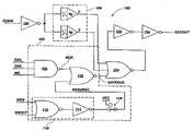
- FIG. 1is a schematic diagram of clock control circuitry 100 in accordance with the present invention.
- Clock control circuitry 100receives a system clock (CLKIN) as an input signal and selectively outputs an internal clock (CLKOUT) for use by other synchronous circuits.
- Clock control circuitry 100may include command detection circuitry 102 and clock gating circuitry 104 coupled to said command detection circuitry 102 .
- Clock control circuitry 100may also include delay circuitry 106 for delaying a system clock to compensate for delays in the command detection circuitry 102 .
- Command detection circuitry 102may include any circuitry for monitoring command signal inputs to determine occurrence of an active command, e.g., a read or write command, or, alternatively, if the memory device is to remain idle, e.g., a no operation (NOP) command.
- command detection circuitry 102may include a 3-input NAND gate 108 for sensing an NOP command. During an NOP command, no action or operation takes place in response to command signal inputs. It is desirable to turn off an unneeded internal clock during an NOP command.
- an NOP commandmay be sensed by the signals row-address strobe (RAS_), column-address strobe (CAS_) and write enable (WE_) as shown in FIG. 1 .
- RAS_row-address strobe
- CAS_column-address strobe
- WE_write enable
- the “_” symbol appended to RAS_, CAS_ and WE_indicates that the signals RAS_, CAS_ and WE_ are active low.
- selecting RAS, CAS and WE to be active high or active lowis a simple matter of logic design.
- the use of active low RAS_, CAS — and WE —is merely exemplary.
- Three-input NAND gate 108will output signal NOP — (active low) indicating an NOP command if RAS_, CAS — and WE — are all high.
- Command detection circuitry 102may also include burst detection circuitry 110 .
- Burst detection circuitry 110detects whether or not a read or write (read/write) burst operation is taking place. While it is desirable to turn off an internal clock during idle time, it is important to distribute an internal clock during read/write burst operations. If a read/write burst operation is taking place, burst detection circuitry 110 provides a signal to clock gating circuitry 104 allowing distribution of a system clock as an internal clock, regardless of the output of 3-input NAND gate 108 and the presence of an NOP command. As shown in FIG.
- Command detection circuitry 102may further include bypass circuitry 116 for selectively bypassing the power conservation feature of the clock control circuitry 100 .
- Bypass circuitry 116may be a switch (as illustrated) or may be a nonvolatile programmable element such as a fuse or antifuse, or may be a volatile switching element such as a transistor, latch or register, or any other suitable means for setting the value of signal NOBURST_.
- Command detection circuitry 102may further include a 2-input NOR gate 118 for receiving signals NOP — and NOBURST — and outputting signal GATECLK_. If signal GATECLK — is held high, output signal CLKOUT will always be held low regardless of levels or edges on input signal CLKIN.
- Command detection circuitry 102may further include an input inverter 120 and output inverters 122 and 124 for buffering the input signal CLKIN and output signal CLKOUT, respectively.
- Output inverters 122 and 124may be sized to drive an appropriate fan out as known to one of ordinary skill in the art.
- FIG. 2is a schematic diagram of clock control circuitry 200 according to the present invention.
- Clock control circuitry 200may include command detection circuitry 202 , burst detection circuitry 204 and clock gating circuitry 206 coupled to the command detection circuitry 202 and the burst detection circuitry 204 .
- the output signal CLKOUT_EN —may be used by other circuitry (not shown in FIG. 2 , but see FIG. 3 and related discussion below) to disable distribution of a system clock (not shown) to other internal circuitry during idle time, thereby reducing power consumption.
- Input signals to clock control circuitry 200may include command signals such as FCMD — ⁇ 0:3>, which may be decoded to determine when an active command or NOP command is present; a preclock signal PRE_CK, which may be used to qualify commands in a register 208 (see below); input clock signal CLKPDQ_, which is indicative of the system clock signal (not shown) that is to be distributed internally or not; register burst control signals such as RB ⁇ 0:3>, which may be decoded along with an enable out ENOUT signal to determine whether or not a read/write burst operation is being executed.
- command signalssuch as FCMD — ⁇ 0:3>, which may be decoded to determine when an active command or NOP command is present
- PRE_CKwhich may be used to qualify commands in a register 208 (see below)
- input clock signal CLKPDQ_which is indicative of the system clock signal (not shown) that is to be distributed internally or not
- register burst control signalssuch as RB ⁇ 0:3>,
- An optional power up PWRUP signalmay also be input to clock control circuitry 200 for forcing the output signal CLKOUT_EN — to an on state until a valid power up condition is detected. Additionally, signals TEST and PFTM may be used as spare control signals for test modes. The output signal to clock control circuitry 200 may include CLKOUT_EN — as further described below.
- Clock control circuitry 200may further include a register 208 coupled to the command detection circuitry 202 for assuring valid commands and avoiding potential race conditions. Register 208 may avoid race conditions by ensuring CLKOUT_EN — is low for a minimum of two preclock pulses for every active command. The operation of register 208 will be apparent to one of ordinary skill in the art and, thus, will not be further elaborated herein. Clock control circuitry 200 may further include delay circuitry 216 to adjust the timing of input clock signal CLKPDQ — relative to delays caused by the burst detection circuitry 204 .
- Burst detection circuitry 204may include optional bypass circuitry 210 to disable the power savings feature of the clock control circuitry 200 .
- Optional bypass circuitry 210may be a switch (as illustrated) or may be a nonvolatile programmable element such as a fuse or antifuse, or may be a volatile switching element such as a transistor, latch or register, or any other suitable means for disabling the power savings feature of the clock control circuitry 200 of the present invention.
- Burst detection circuitry 204may further include spare control circuitry 212 for test modes as known to one of ordinary skill in the art.
- Command detection circuitry 202may be used to decode command signals to determine whether an NOP command has been issued or not.
- Command detection circuitry 202may be a 4-input NAND gate 214 for detecting signals on FCMD — ⁇ 0:3> corresponding to RAS, CAS and WE as described above and chip select (CS). If all four bits or signals of FCMD — ⁇ 0:3> are high, then an NOP command has been detected. Otherwise, some other active command is present.
- Other logically equivalent combinations of gatesmay be substituted for the command detection circuitry 202 illustrated in FIG. 2 and are considered to be within the spirit and scope of the present invention.
- Clock control circuitry 200may be used on any applicable dynamic random access memory (DRAM) memory device, for example and not by way of limitation, a dynamic random access memory (DRAM), double data rate SDRAM (DDR SDRAM), RAMBUS® DRAM (RDRAM®), extended data-out DRAM (EDO DRAM) and fast-page-mode DRAM (FPM DRAM).
- DRAMdynamic random access memory
- DDR SDRAMdouble data rate SDRAM
- RDRAM®RAMBUS® DRAM
- EEO DRAMextended data-out DRAM
- FPM DRAMfast-page-mode DRAM
- FIG. 3is a schematic diagram of a clock buffer 300 including clock control circuitry 200 in accordance with the present invention for selectively driving one or more internal clocks derived from a system clock.
- Clock buffer 300may also include clock receiving circuitry 304 for receiving an external system clock labeled “clk” in FIG. 3 .
- Clock control circuitry 200provides CLKOUT_EN — as an active low signal to disable an internal clock when not needed.
- Clock buffer 300may further include other circuitry for receiving CLKOUT_EN — and disabling distribution of the external system clock “clk” if CLKOUT_EN — is low.
- clock buffer 300may include clock pulse circuitry 302 (labeled “clk_pulse,” two of which are shown in FIG.
- Clock buffer 300selectively delivers internal clock signal CLKPDQ in accordance with the state of CLKOUT_EN_. For example, if CLKOUT_EN — is low, then internal clock signal CLKPDQ is output from clock buffer 300 , whereas if CLKOUT_EN — is high, internal clock signal CLKPDQ is disabled, thus reducing power consumption. Thus, CLKOUT_EN — is used to enable or disable CLKP_.
- FIG. 4is a block diagram of a memory device 400 that may include clock control circuitry 100 and 200 or clock buffer 300 according to the present invention.
- Memory device 400may be, for example and not by way of limitation, a dynamic random access memory (DRAM), double data rate SDRAM (DDR SDRAM), RAMBUS® DRAM (RDRAM®), extended data-out DRAM (EDO DRAM) or fast-page-mode DRAM (FPM DRAM).
- DRAMdynamic random access memory
- DDR SDRAMdouble data rate SDRAM
- RDRAM®RAMBUS® DRAM
- EEO DRAMextended data-out DRAM
- FPM DRAMfast-page-mode DRAM
- FIG. 5is a flow chart of a method 500 of reducing power consumption in a memory device in accordance with the present invention.
- Method 500may include sensing 502 a no operation (NOP) command, determining 504 whether or not a read/write burst operation is active and selectively turning off 506 distribution of a system clock within a memory device if the NOP command is active and the read/write burst operation is not active.
- Sensing 502 an NOP commandmay include monitoring RAS, CAS, WE and CS signals.
- Determining 504 whether or not a read/write burst operation is activemay include monitoring register burst control and enable out signals.
- a plan view of a semiconductor substrate 600is shown including at least one IC die 602 (only one of which is shown for clarity).
- Each IC die 602may be a memory device 400 including clock control circuitry 100 , 200 and/or clock buffer 300 of the present invention.
- integrated circuit die 602may be any other integrated circuit that may have an internal clock that may be turned off during idle time in accordance with the present invention.
- Semiconductor substrate 600may be a silicon wafer or other large-scale substrate comprising a layer of semiconductor material.
- siliconis the preferred bulk semiconductor material for commercial electronic devices
- gallium arsenide and indium phosphide substratesmay also be employed.
- the devices of the present inventionmay be fabricated on other semiconductor substrates as well, including, for example, silicon-on-glass (SOG) substrates, silicon-on-insulator (SOI) substrates, and silicon-on-sapphire (SOS) substrates.
- SOGsilicon-on-glass
- SOIsilicon-on-insulator
- SOSsilicon-on-sapphire
- FIG. 7is a block diagram of a computer system 700 in accordance with the present invention.
- System 700may include an input device 702 , output device 704 and processor 706 in communication with the input device 702 and output device 704 .
- System 700may further include a memory device 400 including clock control circuitry 100 , 200 and/or clock buffer 300 of the present invention.
Landscapes
- Engineering & Computer Science (AREA)
- Theoretical Computer Science (AREA)
- Physics & Mathematics (AREA)
- General Engineering & Computer Science (AREA)
- General Physics & Mathematics (AREA)
- Dram (AREA)
Abstract
Description
Claims (31)
Priority Applications (5)
| Application Number | Priority Date | Filing Date | Title |
|---|---|---|---|
| US10/179,882US7089438B2 (en) | 2002-06-25 | 2002-06-25 | Circuit, system and method for selectively turning off internal clock drivers |
| US11/449,499US7669068B2 (en) | 2002-06-25 | 2006-06-07 | Circuit, system and method for selectively turning off internal clock drivers |
| US12/652,897US8412968B2 (en) | 2002-06-25 | 2010-01-06 | Circuit, system and method for selectively turning off internal clock drivers |
| US13/796,677US9003214B2 (en) | 2002-06-25 | 2013-03-12 | Circuit, system and method for selectively turning off internal clock drivers |
| US14/659,934US9201489B2 (en) | 2002-06-25 | 2015-03-17 | Circuit, system and method for selectively turning off internal clock drivers |
Applications Claiming Priority (1)
| Application Number | Priority Date | Filing Date | Title |
|---|---|---|---|
| US10/179,882US7089438B2 (en) | 2002-06-25 | 2002-06-25 | Circuit, system and method for selectively turning off internal clock drivers |
Related Child Applications (1)
| Application Number | Title | Priority Date | Filing Date |
|---|---|---|---|
| US11/449,499ContinuationUS7669068B2 (en) | 2002-06-25 | 2006-06-07 | Circuit, system and method for selectively turning off internal clock drivers |
Publications (2)
| Publication Number | Publication Date |
|---|---|
| US20030235103A1 US20030235103A1 (en) | 2003-12-25 |
| US7089438B2true US7089438B2 (en) | 2006-08-08 |
Family
ID=29735004
Family Applications (5)
| Application Number | Title | Priority Date | Filing Date |
|---|---|---|---|
| US10/179,882Expired - LifetimeUS7089438B2 (en) | 2002-06-25 | 2002-06-25 | Circuit, system and method for selectively turning off internal clock drivers |
| US11/449,499Expired - LifetimeUS7669068B2 (en) | 2002-06-25 | 2006-06-07 | Circuit, system and method for selectively turning off internal clock drivers |
| US12/652,897Expired - Fee RelatedUS8412968B2 (en) | 2002-06-25 | 2010-01-06 | Circuit, system and method for selectively turning off internal clock drivers |
| US13/796,677Expired - Fee RelatedUS9003214B2 (en) | 2002-06-25 | 2013-03-12 | Circuit, system and method for selectively turning off internal clock drivers |
| US14/659,934Expired - Fee RelatedUS9201489B2 (en) | 2002-06-25 | 2015-03-17 | Circuit, system and method for selectively turning off internal clock drivers |
Family Applications After (4)
| Application Number | Title | Priority Date | Filing Date |
|---|---|---|---|
| US11/449,499Expired - LifetimeUS7669068B2 (en) | 2002-06-25 | 2006-06-07 | Circuit, system and method for selectively turning off internal clock drivers |
| US12/652,897Expired - Fee RelatedUS8412968B2 (en) | 2002-06-25 | 2010-01-06 | Circuit, system and method for selectively turning off internal clock drivers |
| US13/796,677Expired - Fee RelatedUS9003214B2 (en) | 2002-06-25 | 2013-03-12 | Circuit, system and method for selectively turning off internal clock drivers |
| US14/659,934Expired - Fee RelatedUS9201489B2 (en) | 2002-06-25 | 2015-03-17 | Circuit, system and method for selectively turning off internal clock drivers |
Country Status (1)
| Country | Link |
|---|---|
| US (5) | US7089438B2 (en) |
Cited By (47)
| Publication number | Priority date | Publication date | Assignee | Title |
|---|---|---|---|---|
| US20060015704A1 (en)* | 2004-07-14 | 2006-01-19 | Nec Electronics Corporation | Operation apparatus and instruction code executing method |
| US20060230303A1 (en)* | 2002-06-25 | 2006-10-12 | Raad George B | Circuit, system and method for selectively turning off internal clock drivers |
| US20070192576A1 (en)* | 2006-02-16 | 2007-08-16 | Moore Charles H | Circular register arrays of a computer |
| US20070192504A1 (en)* | 2006-02-16 | 2007-08-16 | Moore Charles H | Asynchronous computer communication |
| US20070242076A1 (en)* | 2006-04-13 | 2007-10-18 | Eric Samson | Low power display mode |
| US20070291572A1 (en)* | 2006-06-20 | 2007-12-20 | Josef Schnell | Clock circuit for semiconductor memory |
| US20080037353A1 (en)* | 2006-07-31 | 2008-02-14 | Metaram, Inc. | Interface circuit system and method for performing power saving operations during a command-related latency |
| US7379316B2 (en) | 2005-09-02 | 2008-05-27 | Metaram, Inc. | Methods and apparatus of stacking DRAMs |
| US7386656B2 (en) | 2006-07-31 | 2008-06-10 | Metaram, Inc. | Interface circuit system and method for performing power management operations in conjunction with only a portion of a memory circuit |
| US7392338B2 (en) | 2006-07-31 | 2008-06-24 | Metaram, Inc. | Interface circuit system and method for autonomously performing power management operations in conjunction with a plurality of memory circuits |
| US7472220B2 (en) | 2006-07-31 | 2008-12-30 | Metaram, Inc. | Interface circuit system and method for performing power management operations utilizing power management signals |
| US7515453B2 (en) | 2005-06-24 | 2009-04-07 | Metaram, Inc. | Integrated memory core and memory interface circuit |
| US7580312B2 (en) | 2006-07-31 | 2009-08-25 | Metaram, Inc. | Power saving system and method for use with a plurality of memory circuits |
| US7609567B2 (en) | 2005-06-24 | 2009-10-27 | Metaram, Inc. | System and method for simulating an aspect of a memory circuit |
| US20100023730A1 (en)* | 2008-07-24 | 2010-01-28 | Vns Portfolio Llc | Circular Register Arrays of a Computer |
| US7724589B2 (en) | 2006-07-31 | 2010-05-25 | Google Inc. | System and method for delaying a signal communicated from a system to at least one of a plurality of memory circuits |
| US7904695B2 (en) | 2006-02-16 | 2011-03-08 | Vns Portfolio Llc | Asynchronous power saving computer |
| US7966481B2 (en) | 2006-02-16 | 2011-06-21 | Vns Portfolio Llc | Computer system and method for executing port communications without interrupting the receiving computer |
| US8019589B2 (en) | 2006-07-31 | 2011-09-13 | Google Inc. | Memory apparatus operable to perform a power-saving operation |
| US8055833B2 (en) | 2006-10-05 | 2011-11-08 | Google Inc. | System and method for increasing capacity, performance, and flexibility of flash storage |
| US8060774B2 (en) | 2005-06-24 | 2011-11-15 | Google Inc. | Memory systems and memory modules |
| US20110302660A1 (en)* | 2010-06-02 | 2011-12-08 | Rupaka Mahalingaiah | Method and apparatus for securing digital devices with locking clock mechanism |
| US8077535B2 (en) | 2006-07-31 | 2011-12-13 | Google Inc. | Memory refresh apparatus and method |
| US8081474B1 (en) | 2007-12-18 | 2011-12-20 | Google Inc. | Embossed heat spreader |
| US8080874B1 (en) | 2007-09-14 | 2011-12-20 | Google Inc. | Providing additional space between an integrated circuit and a circuit board for positioning a component therebetween |
| US8090897B2 (en) | 2006-07-31 | 2012-01-03 | Google Inc. | System and method for simulating an aspect of a memory circuit |
| US8089795B2 (en) | 2006-02-09 | 2012-01-03 | Google Inc. | Memory module with memory stack and interface with enhanced capabilities |
| US8111566B1 (en) | 2007-11-16 | 2012-02-07 | Google, Inc. | Optimal channel design for memory devices for providing a high-speed memory interface |
| US8130560B1 (en) | 2006-11-13 | 2012-03-06 | Google Inc. | Multi-rank partial width memory modules |
| US8169233B2 (en) | 2009-06-09 | 2012-05-01 | Google Inc. | Programming of DIMM termination resistance values |
| US8209479B2 (en) | 2007-07-18 | 2012-06-26 | Google Inc. | Memory circuit system and method |
| US8244971B2 (en) | 2006-07-31 | 2012-08-14 | Google Inc. | Memory circuit system and method |
| US8280714B2 (en) | 2006-07-31 | 2012-10-02 | Google Inc. | Memory circuit simulation system and method with refresh capabilities |
| US8327104B2 (en) | 2006-07-31 | 2012-12-04 | Google Inc. | Adjusting the timing of signals associated with a memory system |
| US8335894B1 (en) | 2008-07-25 | 2012-12-18 | Google Inc. | Configurable memory system with interface circuit |
| US8386722B1 (en) | 2008-06-23 | 2013-02-26 | Google Inc. | Stacked DIMM memory interface |
| US8397013B1 (en) | 2006-10-05 | 2013-03-12 | Google Inc. | Hybrid memory module |
| US8438328B2 (en) | 2008-02-21 | 2013-05-07 | Google Inc. | Emulation of abstracted DIMMs using abstracted DRAMs |
| US8566516B2 (en) | 2006-07-31 | 2013-10-22 | Google Inc. | Refresh management of memory modules |
| US8796830B1 (en) | 2006-09-01 | 2014-08-05 | Google Inc. | Stackable low-profile lead frame package |
| US8972673B2 (en) | 2006-07-31 | 2015-03-03 | Google Inc. | Power management of memory circuits by virtual memory simulation |
| US9000804B2 (en) | 2010-03-03 | 2015-04-07 | Freescale Semiconductor, Inc. | Integrated circuit device comprising clock gating circuitry, electronic device and method for dynamically configuring clock gating |
| US9171585B2 (en) | 2005-06-24 | 2015-10-27 | Google Inc. | Configurable memory circuit system and method |
| US9507739B2 (en) | 2005-06-24 | 2016-11-29 | Google Inc. | Configurable memory circuit system and method |
| US9542353B2 (en) | 2006-02-09 | 2017-01-10 | Google Inc. | System and method for reducing command scheduling constraints of memory circuits |
| US9632929B2 (en) | 2006-02-09 | 2017-04-25 | Google Inc. | Translating an address associated with a command communicated between a system and memory circuits |
| US10013371B2 (en) | 2005-06-24 | 2018-07-03 | Google Llc | Configurable memory circuit system and method |
Families Citing this family (6)
| Publication number | Priority date | Publication date | Assignee | Title |
|---|---|---|---|---|
| WO2008010795A1 (en) | 2006-07-18 | 2008-01-24 | Agere Systems Inc. | Systems and methods for modular power management |
| US20130073889A1 (en)* | 2008-08-26 | 2013-03-21 | Richard Rauschmayer | Systems and Methods for Modular Power Management |
| US20150003172A1 (en)* | 2013-06-26 | 2015-01-01 | Sua KIM | Memory module including buffer chip controlling refresh operation of memory devices |
| JP6711590B2 (en)* | 2015-10-30 | 2020-06-17 | キヤノン株式会社 | Information processing device for controlling memory |
| JP2023530110A (en)* | 2020-06-11 | 2023-07-13 | テクトロニクス・インコーポレイテッド | Circular loop image display of waveform data |
| KR20230047823A (en)* | 2021-10-01 | 2023-04-10 | 삼성전자주식회사 | System on chip and application processor |
Citations (16)
| Publication number | Priority date | Publication date | Assignee | Title |
|---|---|---|---|---|
| US5355501A (en)* | 1990-03-09 | 1994-10-11 | Novell, Inc. | Idle detection system |
| US5615376A (en) | 1994-08-03 | 1997-03-25 | Neomagic Corp. | Clock management for power reduction in a video display sub-system |
| US5630107A (en)* | 1992-09-30 | 1997-05-13 | Intel Corporation | System for loading PLL from bus fraction register when bus fraction register is in either first or second state and bus unit not busy |
| US5752045A (en)* | 1995-07-14 | 1998-05-12 | United Microelectronics Corporation | Power conservation in synchronous SRAM cache memory blocks of a computer system |
| US5887178A (en)* | 1994-08-29 | 1999-03-23 | Matsushita Electronics Corporation | Idle state detector and idle state detecting method for a microprocessor unit for power savings |
| US5918058A (en) | 1997-02-20 | 1999-06-29 | Arm Limited | Routing of clock signals in a data processing circuit with a power saving mode of operation |
| US5933649A (en)* | 1994-06-20 | 1999-08-03 | Samsung Electronics Co., Ltd. | Method and device for controlling a CPU stop clock interrupt |
| US6073223A (en)* | 1997-07-21 | 2000-06-06 | Hewlett-Packard Company | Memory controller and method for intermittently activating and idling a clock signal for a synchronous memory |
| US6079025A (en) | 1990-06-01 | 2000-06-20 | Vadem | System and method of computer operating mode control for power consumption reduction |
| USRE36839E (en) | 1995-02-14 | 2000-08-29 | Philips Semiconductor, Inc. | Method and apparatus for reducing power consumption in digital electronic circuits |
| US6138205A (en)* | 1997-08-28 | 2000-10-24 | Nec Corporation | Burst mode type semiconductor memory device |
| US6300807B1 (en) | 1998-09-04 | 2001-10-09 | Hitachi, Ltd. | Timing-control circuit device and clock distribution system |
| US20020184438A1 (en)* | 2001-05-31 | 2002-12-05 | Fujitsu Limited | Memory control system |
| US6657634B1 (en)* | 1999-02-25 | 2003-12-02 | Ati International Srl | Dynamic graphics and/or video memory power reducing circuit and method |
| US6678832B1 (en)* | 1998-10-29 | 2004-01-13 | Matsushita Electric Industrial Co., Ltd. | Memory controller for controlling an integrated memory undergoing logical state transitions |
| US6772359B2 (en)* | 1999-11-30 | 2004-08-03 | Hyundai Electronics Industries Co., Ltd. | Clock control circuit for Rambus DRAM |
Family Cites Families (10)
| Publication number | Priority date | Publication date | Assignee | Title |
|---|---|---|---|---|
| US5652733A (en)* | 1996-04-29 | 1997-07-29 | Mosaid Technologies Inc. | Command encoded delayed clock generator |
| US6157990A (en)* | 1997-03-07 | 2000-12-05 | Mitsubishi Electronics America Inc. | Independent chip select for SRAM and DRAM in a multi-port RAM |
| US5881016A (en)* | 1997-06-13 | 1999-03-09 | Cirrus Logic, Inc. | Method and apparatus for optimizing power consumption and memory bandwidth in a video controller using SGRAM and SDRAM power reduction modes |
| US6848058B1 (en)* | 1999-06-04 | 2005-01-25 | Ati International Srl | Power reduction circuit and method with multi clock branch control |
| JP3420120B2 (en)* | 1999-06-29 | 2003-06-23 | 日本電気株式会社 | Synchronous semiconductor memory system |
| US7073014B1 (en)* | 2000-07-28 | 2006-07-04 | Micron Technology, Inc. | Synchronous non-volatile memory system |
| JP3923715B2 (en)* | 2000-09-29 | 2007-06-06 | 株式会社東芝 | Memory card |
| JP2002216472A (en)* | 2001-01-22 | 2002-08-02 | Nec Corp | Semiconductor memory device |
| US7107471B2 (en)* | 2001-03-21 | 2006-09-12 | Apple Computer, Inc. | Method and apparatus for saving power in pipelined processors |
| US7089438B2 (en)* | 2002-06-25 | 2006-08-08 | Micron Technology, Inc. | Circuit, system and method for selectively turning off internal clock drivers |
- 2002
- 2002-06-25USUS10/179,882patent/US7089438B2/ennot_activeExpired - Lifetime
- 2006
- 2006-06-07USUS11/449,499patent/US7669068B2/ennot_activeExpired - Lifetime
- 2010
- 2010-01-06USUS12/652,897patent/US8412968B2/ennot_activeExpired - Fee Related
- 2013
- 2013-03-12USUS13/796,677patent/US9003214B2/ennot_activeExpired - Fee Related
- 2015
- 2015-03-17USUS14/659,934patent/US9201489B2/ennot_activeExpired - Fee Related
Patent Citations (16)
| Publication number | Priority date | Publication date | Assignee | Title |
|---|---|---|---|---|
| US5355501A (en)* | 1990-03-09 | 1994-10-11 | Novell, Inc. | Idle detection system |
| US6079025A (en) | 1990-06-01 | 2000-06-20 | Vadem | System and method of computer operating mode control for power consumption reduction |
| US5630107A (en)* | 1992-09-30 | 1997-05-13 | Intel Corporation | System for loading PLL from bus fraction register when bus fraction register is in either first or second state and bus unit not busy |
| US5933649A (en)* | 1994-06-20 | 1999-08-03 | Samsung Electronics Co., Ltd. | Method and device for controlling a CPU stop clock interrupt |
| US5615376A (en) | 1994-08-03 | 1997-03-25 | Neomagic Corp. | Clock management for power reduction in a video display sub-system |
| US5887178A (en)* | 1994-08-29 | 1999-03-23 | Matsushita Electronics Corporation | Idle state detector and idle state detecting method for a microprocessor unit for power savings |
| USRE36839E (en) | 1995-02-14 | 2000-08-29 | Philips Semiconductor, Inc. | Method and apparatus for reducing power consumption in digital electronic circuits |
| US5752045A (en)* | 1995-07-14 | 1998-05-12 | United Microelectronics Corporation | Power conservation in synchronous SRAM cache memory blocks of a computer system |
| US5918058A (en) | 1997-02-20 | 1999-06-29 | Arm Limited | Routing of clock signals in a data processing circuit with a power saving mode of operation |
| US6073223A (en)* | 1997-07-21 | 2000-06-06 | Hewlett-Packard Company | Memory controller and method for intermittently activating and idling a clock signal for a synchronous memory |
| US6138205A (en)* | 1997-08-28 | 2000-10-24 | Nec Corporation | Burst mode type semiconductor memory device |
| US6300807B1 (en) | 1998-09-04 | 2001-10-09 | Hitachi, Ltd. | Timing-control circuit device and clock distribution system |
| US6678832B1 (en)* | 1998-10-29 | 2004-01-13 | Matsushita Electric Industrial Co., Ltd. | Memory controller for controlling an integrated memory undergoing logical state transitions |
| US6657634B1 (en)* | 1999-02-25 | 2003-12-02 | Ati International Srl | Dynamic graphics and/or video memory power reducing circuit and method |
| US6772359B2 (en)* | 1999-11-30 | 2004-08-03 | Hyundai Electronics Industries Co., Ltd. | Clock control circuit for Rambus DRAM |
| US20020184438A1 (en)* | 2001-05-31 | 2002-12-05 | Fujitsu Limited | Memory control system |
Non-Patent Citations (1)
| Title |
|---|
| Micron Production Data Sheet and Specification, "Synchronous Dram," pp. 1-55, Micron Technology, Inc., 2000. |
Cited By (92)
| Publication number | Priority date | Publication date | Assignee | Title |
|---|---|---|---|---|
| US20100174932A1 (en)* | 2002-06-25 | 2010-07-08 | Mosaid Technologies Incorporated | Circuit, system and method for selectively turning off internal clock drivers |
| US20060230303A1 (en)* | 2002-06-25 | 2006-10-12 | Raad George B | Circuit, system and method for selectively turning off internal clock drivers |
| US9201489B2 (en)* | 2002-06-25 | 2015-12-01 | Conversant Intellectual Property Management Inc. | Circuit, system and method for selectively turning off internal clock drivers |
| US7669068B2 (en)* | 2002-06-25 | 2010-02-23 | Mosaid Technologies Incorporated | Circuit, system and method for selectively turning off internal clock drivers |
| US8412968B2 (en) | 2002-06-25 | 2013-04-02 | Mosaid Technologies Incorporated | Circuit, system and method for selectively turning off internal clock drivers |
| US9003214B2 (en) | 2002-06-25 | 2015-04-07 | Conversant Intellectual Property Management Inc. | Circuit, system and method for selectively turning off internal clock drivers |
| US20060015704A1 (en)* | 2004-07-14 | 2006-01-19 | Nec Electronics Corporation | Operation apparatus and instruction code executing method |
| US8386833B2 (en) | 2005-06-24 | 2013-02-26 | Google Inc. | Memory systems and memory modules |
| US8615679B2 (en) | 2005-06-24 | 2013-12-24 | Google Inc. | Memory modules with reliability and serviceability functions |
| US8060774B2 (en) | 2005-06-24 | 2011-11-15 | Google Inc. | Memory systems and memory modules |
| US10013371B2 (en) | 2005-06-24 | 2018-07-03 | Google Llc | Configurable memory circuit system and method |
| US7515453B2 (en) | 2005-06-24 | 2009-04-07 | Metaram, Inc. | Integrated memory core and memory interface circuit |
| US7609567B2 (en) | 2005-06-24 | 2009-10-27 | Metaram, Inc. | System and method for simulating an aspect of a memory circuit |
| US9507739B2 (en) | 2005-06-24 | 2016-11-29 | Google Inc. | Configurable memory circuit system and method |
| US8359187B2 (en) | 2005-06-24 | 2013-01-22 | Google Inc. | Simulating a different number of memory circuit devices |
| US9171585B2 (en) | 2005-06-24 | 2015-10-27 | Google Inc. | Configurable memory circuit system and method |
| US8619452B2 (en) | 2005-09-02 | 2013-12-31 | Google Inc. | Methods and apparatus of stacking DRAMs |
| US8582339B2 (en) | 2005-09-02 | 2013-11-12 | Google Inc. | System including memory stacks |
| US7599205B2 (en) | 2005-09-02 | 2009-10-06 | Metaram, Inc. | Methods and apparatus of stacking DRAMs |
| US7379316B2 (en) | 2005-09-02 | 2008-05-27 | Metaram, Inc. | Methods and apparatus of stacking DRAMs |
| US8811065B2 (en) | 2005-09-02 | 2014-08-19 | Google Inc. | Performing error detection on DRAMs |
| US9727458B2 (en) | 2006-02-09 | 2017-08-08 | Google Inc. | Translating an address associated with a command communicated between a system and memory circuits |
| US9632929B2 (en) | 2006-02-09 | 2017-04-25 | Google Inc. | Translating an address associated with a command communicated between a system and memory circuits |
| US8797779B2 (en) | 2006-02-09 | 2014-08-05 | Google Inc. | Memory module with memory stack and interface with enhanced capabilites |
| US9542352B2 (en) | 2006-02-09 | 2017-01-10 | Google Inc. | System and method for reducing command scheduling constraints of memory circuits |
| US8089795B2 (en) | 2006-02-09 | 2012-01-03 | Google Inc. | Memory module with memory stack and interface with enhanced capabilities |
| US8566556B2 (en) | 2006-02-09 | 2013-10-22 | Google Inc. | Memory module with memory stack and interface with enhanced capabilities |
| US9542353B2 (en) | 2006-02-09 | 2017-01-10 | Google Inc. | System and method for reducing command scheduling constraints of memory circuits |
| US7904695B2 (en) | 2006-02-16 | 2011-03-08 | Vns Portfolio Llc | Asynchronous power saving computer |
| US20070192504A1 (en)* | 2006-02-16 | 2007-08-16 | Moore Charles H | Asynchronous computer communication |
| US7617383B2 (en) | 2006-02-16 | 2009-11-10 | Vns Portfolio Llc | Circular register arrays of a computer |
| US7966481B2 (en) | 2006-02-16 | 2011-06-21 | Vns Portfolio Llc | Computer system and method for executing port communications without interrupting the receiving computer |
| US7904615B2 (en)* | 2006-02-16 | 2011-03-08 | Vns Portfolio Llc | Asynchronous computer communication |
| US20070192576A1 (en)* | 2006-02-16 | 2007-08-16 | Moore Charles H | Circular register arrays of a computer |
| US8314806B2 (en)* | 2006-04-13 | 2012-11-20 | Intel Corporation | Low power display mode |
| US20070242076A1 (en)* | 2006-04-13 | 2007-10-18 | Eric Samson | Low power display mode |
| US20070291572A1 (en)* | 2006-06-20 | 2007-12-20 | Josef Schnell | Clock circuit for semiconductor memory |
| US8327104B2 (en) | 2006-07-31 | 2012-12-04 | Google Inc. | Adjusting the timing of signals associated with a memory system |
| US8868829B2 (en) | 2006-07-31 | 2014-10-21 | Google Inc. | Memory circuit system and method |
| US20080037353A1 (en)* | 2006-07-31 | 2008-02-14 | Metaram, Inc. | Interface circuit system and method for performing power saving operations during a command-related latency |
| US8154935B2 (en) | 2006-07-31 | 2012-04-10 | Google Inc. | Delaying a signal communicated from a system to at least one of a plurality of memory circuits |
| US7386656B2 (en) | 2006-07-31 | 2008-06-10 | Metaram, Inc. | Interface circuit system and method for performing power management operations in conjunction with only a portion of a memory circuit |
| US7392338B2 (en) | 2006-07-31 | 2008-06-24 | Metaram, Inc. | Interface circuit system and method for autonomously performing power management operations in conjunction with a plurality of memory circuits |
| US8244971B2 (en) | 2006-07-31 | 2012-08-14 | Google Inc. | Memory circuit system and method |
| US8280714B2 (en) | 2006-07-31 | 2012-10-02 | Google Inc. | Memory circuit simulation system and method with refresh capabilities |
| US8112266B2 (en) | 2006-07-31 | 2012-02-07 | Google Inc. | Apparatus for simulating an aspect of a memory circuit |
| US8090897B2 (en) | 2006-07-31 | 2012-01-03 | Google Inc. | System and method for simulating an aspect of a memory circuit |
| US7472220B2 (en) | 2006-07-31 | 2008-12-30 | Metaram, Inc. | Interface circuit system and method for performing power management operations utilizing power management signals |
| US8340953B2 (en) | 2006-07-31 | 2012-12-25 | Google, Inc. | Memory circuit simulation with power saving capabilities |
| US7580312B2 (en) | 2006-07-31 | 2009-08-25 | Metaram, Inc. | Power saving system and method for use with a plurality of memory circuits |
| US7581127B2 (en) | 2006-07-31 | 2009-08-25 | Metaram, Inc. | Interface circuit system and method for performing power saving operations during a command-related latency |
| US7590796B2 (en) | 2006-07-31 | 2009-09-15 | Metaram, Inc. | System and method for power management in memory systems |
| US9047976B2 (en) | 2006-07-31 | 2015-06-02 | Google Inc. | Combined signal delay and power saving for use with a plurality of memory circuits |
| US7724589B2 (en) | 2006-07-31 | 2010-05-25 | Google Inc. | System and method for delaying a signal communicated from a system to at least one of a plurality of memory circuits |
| US8077535B2 (en) | 2006-07-31 | 2011-12-13 | Google Inc. | Memory refresh apparatus and method |
| US8972673B2 (en) | 2006-07-31 | 2015-03-03 | Google Inc. | Power management of memory circuits by virtual memory simulation |
| US7730338B2 (en) | 2006-07-31 | 2010-06-01 | Google Inc. | Interface circuit system and method for autonomously performing power management operations in conjunction with a plurality of memory circuits |
| US7761724B2 (en) | 2006-07-31 | 2010-07-20 | Google Inc. | Interface circuit system and method for performing power management operations in conjunction with only a portion of a memory circuit |
| US8566516B2 (en) | 2006-07-31 | 2013-10-22 | Google Inc. | Refresh management of memory modules |
| US8745321B2 (en) | 2006-07-31 | 2014-06-03 | Google Inc. | Simulating a memory standard |
| US8595419B2 (en) | 2006-07-31 | 2013-11-26 | Google Inc. | Memory apparatus operable to perform a power-saving operation |
| US8601204B2 (en) | 2006-07-31 | 2013-12-03 | Google Inc. | Simulating a refresh operation latency |
| US8041881B2 (en) | 2006-07-31 | 2011-10-18 | Google Inc. | Memory device with emulated characteristics |
| US8019589B2 (en) | 2006-07-31 | 2011-09-13 | Google Inc. | Memory apparatus operable to perform a power-saving operation |
| US8671244B2 (en) | 2006-07-31 | 2014-03-11 | Google Inc. | Simulating a memory standard |
| US8631220B2 (en) | 2006-07-31 | 2014-01-14 | Google Inc. | Adjusting the timing of signals associated with a memory system |
| US8796830B1 (en) | 2006-09-01 | 2014-08-05 | Google Inc. | Stackable low-profile lead frame package |
| US8055833B2 (en) | 2006-10-05 | 2011-11-08 | Google Inc. | System and method for increasing capacity, performance, and flexibility of flash storage |
| US8977806B1 (en) | 2006-10-05 | 2015-03-10 | Google Inc. | Hybrid memory module |
| US8397013B1 (en) | 2006-10-05 | 2013-03-12 | Google Inc. | Hybrid memory module |
| US8370566B2 (en) | 2006-10-05 | 2013-02-05 | Google Inc. | System and method for increasing capacity, performance, and flexibility of flash storage |
| US8751732B2 (en) | 2006-10-05 | 2014-06-10 | Google Inc. | System and method for increasing capacity, performance, and flexibility of flash storage |
| US8446781B1 (en) | 2006-11-13 | 2013-05-21 | Google Inc. | Multi-rank partial width memory modules |
| US8760936B1 (en) | 2006-11-13 | 2014-06-24 | Google Inc. | Multi-rank partial width memory modules |
| US8130560B1 (en) | 2006-11-13 | 2012-03-06 | Google Inc. | Multi-rank partial width memory modules |
| US8209479B2 (en) | 2007-07-18 | 2012-06-26 | Google Inc. | Memory circuit system and method |
| US8080874B1 (en) | 2007-09-14 | 2011-12-20 | Google Inc. | Providing additional space between an integrated circuit and a circuit board for positioning a component therebetween |
| US8675429B1 (en) | 2007-11-16 | 2014-03-18 | Google Inc. | Optimal channel design for memory devices for providing a high-speed memory interface |
| US8111566B1 (en) | 2007-11-16 | 2012-02-07 | Google, Inc. | Optimal channel design for memory devices for providing a high-speed memory interface |
| US8705240B1 (en) | 2007-12-18 | 2014-04-22 | Google Inc. | Embossed heat spreader |
| US8730670B1 (en) | 2007-12-18 | 2014-05-20 | Google Inc. | Embossed heat spreader |
| US8081474B1 (en) | 2007-12-18 | 2011-12-20 | Google Inc. | Embossed heat spreader |
| US8438328B2 (en) | 2008-02-21 | 2013-05-07 | Google Inc. | Emulation of abstracted DIMMs using abstracted DRAMs |
| US8631193B2 (en) | 2008-02-21 | 2014-01-14 | Google Inc. | Emulation of abstracted DIMMS using abstracted DRAMS |
| US8762675B2 (en) | 2008-06-23 | 2014-06-24 | Google Inc. | Memory system for synchronous data transmission |
| US8386722B1 (en) | 2008-06-23 | 2013-02-26 | Google Inc. | Stacked DIMM memory interface |
| US20100023730A1 (en)* | 2008-07-24 | 2010-01-28 | Vns Portfolio Llc | Circular Register Arrays of a Computer |
| US8335894B1 (en) | 2008-07-25 | 2012-12-18 | Google Inc. | Configurable memory system with interface circuit |
| US8819356B2 (en) | 2008-07-25 | 2014-08-26 | Google Inc. | Configurable multirank memory system with interface circuit |
| US8169233B2 (en) | 2009-06-09 | 2012-05-01 | Google Inc. | Programming of DIMM termination resistance values |
| US9000804B2 (en) | 2010-03-03 | 2015-04-07 | Freescale Semiconductor, Inc. | Integrated circuit device comprising clock gating circuitry, electronic device and method for dynamically configuring clock gating |
| US20110302660A1 (en)* | 2010-06-02 | 2011-12-08 | Rupaka Mahalingaiah | Method and apparatus for securing digital devices with locking clock mechanism |
Also Published As
| Publication number | Publication date |
|---|---|
| US7669068B2 (en) | 2010-02-23 |
| US9201489B2 (en) | 2015-12-01 |
| US9003214B2 (en) | 2015-04-07 |
| US20030235103A1 (en) | 2003-12-25 |
| US8412968B2 (en) | 2013-04-02 |
| US20150192982A1 (en) | 2015-07-09 |
| US20130275799A1 (en) | 2013-10-17 |
| US20060230303A1 (en) | 2006-10-12 |
| US20100174932A1 (en) | 2010-07-08 |
Similar Documents
| Publication | Publication Date | Title |
|---|---|---|
| US9201489B2 (en) | Circuit, system and method for selectively turning off internal clock drivers | |
| US5860127A (en) | Cache memory employing dynamically controlled data array start timing and a microcomputer using the same | |
| US7646649B2 (en) | Memory device with programmable receivers to improve performance | |
| US7302598B2 (en) | Apparatus to reduce the internal frequency of an integrated circuit by detecting a drop in the voltage and frequency | |
| US9001572B2 (en) | System on chip including dual power rail and voltage supply method thereof | |
| US6597620B1 (en) | Storage circuit with data retention during power down | |
| KR100779871B1 (en) | Low power auto-refresh circuit and method for dynamic random access memories | |
| US7218568B2 (en) | Circuit and method for operating a delay-lock loop in a power saving manner | |
| US11270754B2 (en) | Apparatuses and methods for dynamic voltage and frequency switching for dynamic random access memory | |
| US20120275236A1 (en) | Method and Apparatus for Power Domain Isolation during Power Down | |
| US8320212B2 (en) | Voltage stabilization circuit and semiconductor memory apparatus using the same | |
| US8406080B2 (en) | Data output control circuit of a double data rate (DDR) synchronous semiconductor memory device responsive to a delay locked loop (DLL) clock and method thereof | |
| US6101144A (en) | Integrated circuit memory devices having automatically induced standby modes and methods of operating same | |
| US7519850B2 (en) | Method and unit for buffer control | |
| US7516350B2 (en) | Dynamic frequency scaling sequence for multi-gigahertz microprocessors | |
| US10712807B2 (en) | Methods and apparatus for saving always on (AON) routing of signals across chips | |
| KR100665408B1 (en) | Differential Amplifier Control Circuit of Semiconductor Memory Device | |
| JPH04123391A (en) | Output buffer circuit for gate array | |
| KR20070086812A (en) | Apparatus and method for reducing power consumption using selective power gating |
Legal Events
| Date | Code | Title | Description |
|---|---|---|---|
| AS | Assignment | Owner name:MICRON TECHNOLOGY, INC., IDAHO Free format text:ASSIGNMENT OF ASSIGNORS INTEREST;ASSIGNOR:RAAD, GEORGE B.;REEL/FRAME:013048/0992 Effective date:20020603 | |
| FEPP | Fee payment procedure | Free format text:PAYOR NUMBER ASSIGNED (ORIGINAL EVENT CODE: ASPN); ENTITY STATUS OF PATENT OWNER: LARGE ENTITY | |
| STCF | Information on status: patent grant | Free format text:PATENTED CASE | |
| AS | Assignment | Owner name:MOSAID TECHNOLOGIES INCORPORATED, CANADA Free format text:ASSIGNMENT OF ASSIGNORS INTEREST;ASSIGNOR:MICRON TECHNOLOGY, INC.;REEL/FRAME:022562/0335 Effective date:20090402 Owner name:MOSAID TECHNOLOGIES INCORPORATED,CANADA Free format text:ASSIGNMENT OF ASSIGNORS INTEREST;ASSIGNOR:MICRON TECHNOLOGY, INC.;REEL/FRAME:022562/0335 Effective date:20090402 | |
| FPAY | Fee payment | Year of fee payment:4 | |
| AS | Assignment | Owner name:ROYAL BANK OF CANADA, CANADA Free format text:U.S. INTELLECTUAL PROPERTY SECURITY AGREEMENT (FOR NON-U.S. GRANTORS) - SHORT FORM;ASSIGNORS:658276 N.B. LTD.;658868 N.B. INC.;MOSAID TECHNOLOGIES INCORPORATED;REEL/FRAME:027512/0196 Effective date:20111223 | |
| FPAY | Fee payment | Year of fee payment:8 | |
| AS | Assignment | Owner name:CONVERSANT INTELLECTUAL PROPERTY MANAGEMENT INC., Free format text:CHANGE OF NAME;ASSIGNOR:MOSAID TECHNOLOGIES INCORPORATED;REEL/FRAME:032439/0638 Effective date:20140101 | |
| AS | Assignment | Owner name:CONVERSANT IP N.B. 276 INC., CANADA Free format text:RELEASE OF SECURITY INTEREST;ASSIGNOR:ROYAL BANK OF CANADA;REEL/FRAME:033484/0344 Effective date:20140611 Owner name:CONVERSANT INTELLECTUAL PROPERTY MANAGEMENT INC., Free format text:RELEASE OF SECURITY INTEREST;ASSIGNOR:ROYAL BANK OF CANADA;REEL/FRAME:033484/0344 Effective date:20140611 Owner name:CONVERSANT IP N.B. 868 INC., CANADA Free format text:RELEASE OF SECURITY INTEREST;ASSIGNOR:ROYAL BANK OF CANADA;REEL/FRAME:033484/0344 Effective date:20140611 | |
| AS | Assignment | Owner name:CONVERSANT INTELLECTUAL PROPERTY MANAGEMENT INC., CANADA Free format text:CHANGE OF ADDRESS;ASSIGNOR:CONVERSANT INTELLECTUAL PROPERTY MANAGEMENT INC.;REEL/FRAME:033678/0096 Effective date:20140820 Owner name:CONVERSANT INTELLECTUAL PROPERTY MANAGEMENT INC., Free format text:CHANGE OF ADDRESS;ASSIGNOR:CONVERSANT INTELLECTUAL PROPERTY MANAGEMENT INC.;REEL/FRAME:033678/0096 Effective date:20140820 | |
| AS | Assignment | Owner name:ROYAL BANK OF CANADA, AS LENDER, CANADA Free format text:U.S. PATENT SECURITY AGREEMENT (FOR NON-U.S. GRANTORS);ASSIGNOR:CONVERSANT INTELLECTUAL PROPERTY MANAGEMENT INC.;REEL/FRAME:033706/0367 Effective date:20140611 Owner name:CPPIB CREDIT INVESTMENTS INC., AS LENDER, CANADA Free format text:U.S. PATENT SECURITY AGREEMENT (FOR NON-U.S. GRANTORS);ASSIGNOR:CONVERSANT INTELLECTUAL PROPERTY MANAGEMENT INC.;REEL/FRAME:033706/0367 Effective date:20140611 | |
| MAFP | Maintenance fee payment | Free format text:PAYMENT OF MAINTENANCE FEE, 12TH YEAR, LARGE ENTITY (ORIGINAL EVENT CODE: M1553) Year of fee payment:12 | |
| AS | Assignment | Owner name:CPPIB CREDIT INVESTMENTS, INC., CANADA Free format text:AMENDED AND RESTATED U.S. PATENT SECURITY AGREEMENT (FOR NON-U.S. GRANTORS);ASSIGNOR:CONVERSANT INTELLECTUAL PROPERTY MANAGEMENT INC.;REEL/FRAME:046900/0136 Effective date:20180731 | |
| AS | Assignment | Owner name:CONVERSANT INTELLECTUAL PROPERTY MANAGEMENT INC., CANADA Free format text:RELEASE OF U.S. PATENT AGREEMENT (FOR NON-U.S. GRANTORS);ASSIGNOR:ROYAL BANK OF CANADA, AS LENDER;REEL/FRAME:047645/0424 Effective date:20180731 Owner name:CONVERSANT INTELLECTUAL PROPERTY MANAGEMENT INC., Free format text:RELEASE OF U.S. PATENT AGREEMENT (FOR NON-U.S. GRANTORS);ASSIGNOR:ROYAL BANK OF CANADA, AS LENDER;REEL/FRAME:047645/0424 Effective date:20180731 | |
| AS | Assignment | Owner name:CONVERSANT INTELLECTUAL PROPERTY MANAGEMENT INC., CANADA Free format text:RELEASE BY SECURED PARTY;ASSIGNOR:CPPIB CREDIT INVESTMENTS INC.;REEL/FRAME:054372/0194 Effective date:20201028 | |
| AS | Assignment | Owner name:MOSAID TECHNOLOGIES INCORPORATED, CANADA Free format text:CHANGE OF NAME;ASSIGNOR:CONVERSANT INTELLECTUAL PROPERTY MANAGEMENT INC.;REEL/FRAME:057709/0853 Effective date:20210401 |