US7089059B1 - Predicting susceptibility to neurological dysfunction based on measured neural electrophysiology - Google Patents
Predicting susceptibility to neurological dysfunction based on measured neural electrophysiologyDownload PDFInfo
- Publication number
- US7089059B1 US7089059B1US09/706,322US70632200AUS7089059B1US 7089059 B1US7089059 B1US 7089059B1US 70632200 AUS70632200 AUS 70632200AUS 7089059 B1US7089059 B1US 7089059B1
- Authority
- US
- United States
- Prior art keywords
- response
- stimulation
- patient
- brain
- excitability
- Prior art date
- Legal status (The legal status is an assumption and is not a legal conclusion. Google has not performed a legal analysis and makes no representation as to the accuracy of the status listed.)
- Expired - Lifetime, expires
Links
Images


Classifications
- A—HUMAN NECESSITIES
- A61—MEDICAL OR VETERINARY SCIENCE; HYGIENE
- A61B—DIAGNOSIS; SURGERY; IDENTIFICATION
- A61B5/00—Measuring for diagnostic purposes; Identification of persons
- A61B5/68—Arrangements of detecting, measuring or recording means, e.g. sensors, in relation to patient
- A61B5/6846—Arrangements of detecting, measuring or recording means, e.g. sensors, in relation to patient specially adapted to be brought in contact with an internal body part, i.e. invasive
- A61B5/6847—Arrangements of detecting, measuring or recording means, e.g. sensors, in relation to patient specially adapted to be brought in contact with an internal body part, i.e. invasive mounted on an invasive device
- A61B5/6864—Burr holes
- A—HUMAN NECESSITIES
- A61—MEDICAL OR VETERINARY SCIENCE; HYGIENE
- A61B—DIAGNOSIS; SURGERY; IDENTIFICATION
- A61B5/00—Measuring for diagnostic purposes; Identification of persons
- A61B5/24—Detecting, measuring or recording bioelectric or biomagnetic signals of the body or parts thereof
- A61B5/316—Modalities, i.e. specific diagnostic methods
- A61B5/369—Electroencephalography [EEG]
- A61B5/377—Electroencephalography [EEG] using evoked responses
- A61B5/383—Somatosensory stimuli, e.g. electric stimulation
- A—HUMAN NECESSITIES
- A61—MEDICAL OR VETERINARY SCIENCE; HYGIENE
- A61B—DIAGNOSIS; SURGERY; IDENTIFICATION
- A61B5/00—Measuring for diagnostic purposes; Identification of persons
- A61B5/40—Detecting, measuring or recording for evaluating the nervous system
- A61B5/4076—Diagnosing or monitoring particular conditions of the nervous system
- A61B5/4094—Diagnosing or monitoring seizure diseases, e.g. epilepsy
- A—HUMAN NECESSITIES
- A61—MEDICAL OR VETERINARY SCIENCE; HYGIENE
- A61B—DIAGNOSIS; SURGERY; IDENTIFICATION
- A61B5/00—Measuring for diagnostic purposes; Identification of persons
- A61B5/72—Signal processing specially adapted for physiological signals or for diagnostic purposes
- A61B5/7203—Signal processing specially adapted for physiological signals or for diagnostic purposes for noise prevention, reduction or removal
- A—HUMAN NECESSITIES
- A61—MEDICAL OR VETERINARY SCIENCE; HYGIENE
- A61N—ELECTROTHERAPY; MAGNETOTHERAPY; RADIATION THERAPY; ULTRASOUND THERAPY
- A61N1/00—Electrotherapy; Circuits therefor
- A61N1/18—Applying electric currents by contact electrodes
- A61N1/32—Applying electric currents by contact electrodes alternating or intermittent currents
- A61N1/36—Applying electric currents by contact electrodes alternating or intermittent currents for stimulation
- A61N1/3605—Implantable neurostimulators for stimulating central or peripheral nerve system
- A61N1/3606—Implantable neurostimulators for stimulating central or peripheral nerve system adapted for a particular treatment
- A61N1/36064—Epilepsy
- A—HUMAN NECESSITIES
- A61—MEDICAL OR VETERINARY SCIENCE; HYGIENE
- A61N—ELECTROTHERAPY; MAGNETOTHERAPY; RADIATION THERAPY; ULTRASOUND THERAPY
- A61N1/00—Electrotherapy; Circuits therefor
- A61N1/18—Applying electric currents by contact electrodes
- A61N1/32—Applying electric currents by contact electrodes alternating or intermittent currents
- A61N1/36—Applying electric currents by contact electrodes alternating or intermittent currents for stimulation
- A61N1/3605—Implantable neurostimulators for stimulating central or peripheral nerve system
- A61N1/36128—Control systems
- A61N1/36135—Control systems using physiological parameters
- A—HUMAN NECESSITIES
- A61—MEDICAL OR VETERINARY SCIENCE; HYGIENE
- A61B—DIAGNOSIS; SURGERY; IDENTIFICATION
- A61B5/00—Measuring for diagnostic purposes; Identification of persons
- A61B5/0002—Remote monitoring of patients using telemetry, e.g. transmission of vital signals via a communication network
- A61B5/0031—Implanted circuitry
Definitions
- the inventionrelates to systems and methods for measuring susceptibility to neurological dysfunction based on analysis of neural electrophysiology, and more particularly to a system and method for determining whether a patient suffering from epilepsy is particularly vulnerable to an imminent epileptic seizure based on periodic analysis of brain evoked response characteristics.
- Epilepsya neurological disorder characterized by the occurrence of seizures (specifically episodic impairment or loss of consciousness, abnormal motor phenomena, psychic or sensory disturbances, or the perturbation of the autonomic nervous system), is debilitating to a great number of people. It is believed that as many as two to four million Americans may suffer from various forms of epilepsy. Research has found that its prevalence may be even greater worldwide, particularly in less economically developed nations, suggesting that the worldwide figure for epilepsy sufferers may be in excess of one hundred million.
- epilepsyis characterized by seizures, its sufferers are frequently limited in the kinds of activities they may participate in. Epilepsy can prevent people from driving, working, or otherwise participating in much of what society has to offer. Some epilepsy sufferers have serious seizures so frequently that they are effectively incapacitated.
- epilepsyis often progressive and can be associated with degenerative disorders and conditions. Over time, epileptic seizures often become more frequent and more serious, and in particularly severe cases, are likely to lead to deterioration of other brain functions (including cognitive function) as well as physical impairments.
- the first approachis usually drug therapy.
- a number of drugsare approved and available for treating epilepsy, such as sodium valproate, phenobarbital/primidone, ethosuximide, gabapentin, phenyloin, and carbamazepine, as well as a number of others.
- drugstypically have serious side effects, especially toxicity, and it is extremely important in most cases to maintain a precise therapeutic serum level to avoid breakthrough seizures (if the dosage is too low) or toxic effects (if the dosage is too high).
- the need for patient disciplineis high, especially when a patient's drug regimen causes unpleasant side effects the patient may wish to avoid.
- Electrical stimulationis an emerging therapy for treating epilepsy.
- currently approved and available electrical stimulation devicesapply continuous electrical stimulation to neural tissue surrounding or near implanted electrodes, and do not perform any detection—they are not responsive to relevant neurological conditions.
- the NeuroCybernetic Prosthesis (NCP) from Cyberonicsapplies continuous electrical stimulation to the patient's vagus nerve. This approach has been found to reduce seizures by about 50% in about 50% of patients. Unfortunately, a much greater reduction in the incidence of seizures is needed to provide clinical benefit.
- the Activa device from Medtronicis a pectorally implanted continuous deep brain stimulator intended primarily to treat Parkinson's disease. In operation, it supplies a continuous electrical pulse stream to a selected deep brain structure where an electrode has been implanted.
- EEGelectroencephalogram
- EoGelectrocorticogram
- EEG signalsrepresent aggregate neuronal activity potentials detectable via electrodes applied to a patient's scalp, and ECoGs use internal electrodes on or near the brain.
- ECoG signalsdeep-brain counterparts to EEG signals, are detectable via electrodes implanted under the dura mater, and sometimes within the patient's brain.
- EEGshall be used generically herein to refer to both EEG and ECoG signals.
- EEG signalsare received by one or more implanted electrodes and then processed by a control module, which then is capable of performing an action (intervention, warning, recording, etc.) when an abnormal event is detected.
- EEG waveformsare filtered and decomposed into “features” representing characteristics of interest in the waveforms.
- One such featureis characterized by the regular occurrence (i.e., density) of half-waves exceeding a threshold amplitude occurring in a specified frequency band between approximately 3 Hz and 20 Hz, especially in comparison to background (non-ictal) activity.
- a threshold amplitudeoccurring in a specified frequency band between approximately 3 Hz and 20 Hz, especially in comparison to background (non-ictal) activity.
- a “false negative” hereinrefers to the failure to detect a seizure or ictal activity that actually is occurring or shortly will occur.
- Known systems for detecting epileptic seizuresare essentially passive in nature (i.e., they receive and process existing signals), and valuable information about the physiological state of the brain is typically not available. Although most or nearly all seizures may be detected by a well-tuned system passive system according to the art, there may be a significant number of false-positive detections, and some seizures may not be detected early enough to facilitate successful treatment.
- EEG waveformsit is presently believed there may not be sufficient information in EEG waveforms to permit accurate detection and prediction of seizures in all cases. And if the information is present, it may be manifested in a way that makes it computationally difficult, if not impossible, to extract it from other EEG contents, such as normal brain activity and noise.
- the present inventionperforms an active analysis of neural electrophysiological parameters to identify susceptibility to imminent seizure activity.
- an embodiment of the inventionperforms periodic active tests of brain tissue excitability and refractoriness (or inhibition) to determine whether hypersynchronous neuronal discharges, which are often characteristic of ictal activity, are more likely than usual to occur.
- the measured parametersserve as predictors for seizure activity. These parameters can be used alone or in combination with the passive EEG-based detection methods described above, or others, to provide enhanced seizure detection and therapeutic capabilities.
- a system and method according to the inventionutilizes an implantable control module and one or more brain electrodes to sense and record EEG signals, perform periodic active neural electrophysiological measurements, compare the signals and measurements to baseline or “normal” conditions (which may be undergo normal changes over time), and perform electrical stimulation (or take other actions) as necessary to terminate a seizure, reduce the likelihood of a seizure occurring, warn the patient that a seizure is about to occur, or record the abnormal activity.
- This measurement stepis described as “active” herein because electrophysiological parameters are measured by providing occasional stimulation pulses to prompt a detectable evoked response, as will be described in fuller detail below, in contrast to “passive” measurement which uses only existing signals for detection.
- a system or method according to the inventionis capable of working in conjunction with and enhancing EEG-based detection and prediction schemes (such as those described in Fischell et al. and Gotman, above).
- the schemeis implemented in an intracranially implanted neurostimulator of the type generally described in Fischell et al., U.S. Pat. No. 6,016,449.
- active sensing of neural electrophysiological parameterscan be used as an alternative detection or seizure prediction method, capable of being selectively activated during the physician's programming process, to be used instead of (or in conjunction with) other detection or prediction methods.
- the various detection methods the device is capable ofare selectively enabled based on the time of day.
- the measured neural electrophysiological parameterscan be used as weighting factors to alter the interpretation of EEG signals.
- EEG-based detection and electrophysiological measurementsare used together to derive an aggregate likelihood of seizure activity.
- electrophysiological parametersas determined by a system or method according to the invention to drive device mode-switches.
- excitability or refractorinesswhen excitability or refractoriness is outside a range determined to be normal, certain other detection methods might be invoked that otherwise would not be performed.
- various actionsmay be taken to alert the patient or head off the seizure. For example, an alarm may be provided to the patient, advising the patient to cease certain activities or take medication, or electrical stimulation or automatic drug delivery may be administered. Continued monitoring of the electrophysiological parameters may be used to adjust the actions taken in a closed loop fashion, to drive the brain state away from the likelihood of developing a seizure.
- the inventionpreferably measures the neural electrophysiological responsiveness of structures and functional pathways in the limbic system, although those skilled in the art will recognize that the measurement of parameters representative of electrophysiological responsiveness in other areas of the brain and in other manners may also be used to advantage in the detection of epileptic seizures (or other neurological disorders) according to the invention.
- measurement of neural electrophysiological parameterscan be accomplished by inserting deep brain electrodes into a patient's hippocampus and parahippocampal gyrus (PHG). Periodically, an electrical stimulation signal is applied to the PHG electrode, and the evoked response in measured in the hippocampus via a signal received by the hippocampus electrode.
- PHGparahippocampal gyrus
- a sequence of signals of various amplitudesis used to determine the excitability threshold.
- a sequence of two-pulse waveforms with variable inter-pulse delaysis used to determine the inhibitory strength. See, e.g., C. L. Wilson, “Neurophysiology of Epileptic Limbic Pathways in Intact Human Temporal Lobe,” in P. Kotagal et al., ed., The Epilepsies: Etiologies and Prevention, San Diego: Academic Press 1999, 171–9.
- the excitability and inhibitory strength parameters determined therebyare then processed and considered in light of baseline values and any trends that may develop.
- An apparatusin one embodiment, would include a control module, at least one brain lead with an electrode, and functionality responsive to the detection of at least one neural electrophysiological parameter.
- the intracranially implanted control modulewould contain a battery and any electronics required to perform the detection, measurement, and treatment schemes enabled by the invention.
- the brain electrodewould be adapted to sense and stimulate in at least two different locations in the patient's brain.
- the electronics in the control modulewould be configured to provide electrical stimulation via the brain lead and electrode to a first location in the patient's brain; any evoked response in a second location in the patient's brain is received by the brain electrode and transmitted to the electronics via the lead.
- the electronicswould be further adapted to selectively perform a method of measuring the neural electrophysiological parameters of excitability and refractoriness (inhibition), as described below, and performing an action in response to the measured parameters or a trend in the measured parameters.
- An embodiment of the method of the invention for sensing excitabilitywould be carried out by providing a stimulation pulse of low amplitude to a first location of the patient's brain, receiving a response signal from a second location of the patient's brain, and processing the response signal to determine whether it is representative of a fully developed evoked response. If the response signal is not representative of an evoked response, the method continues by increasing the amplitude of the stimulation pulse and repeating the providing, receiving, and processing steps. When the response signal represents a fully developed evoked response, the amplitude of the stimulation pulse is deemed to exceed the excitability threshold.
- the “threshold”may be statistical in nature, and more than one determination of the threshold may be used to generate a statistical representation of the threshold.
- An embodiment of the method of the invention for sensing refractorinesswould be carried out by providing a pair of stimulation pulses (each having an amplitude greater than the excitability threshold) separated by a short delay to a first location of the patient's brain, receiving a response signal from a second location of the patient's brain, and processing the response signal to determine whether it represents a single evoked response or a pair of evoked responses. If the response signal represents a single evoked response (the second one having been inhibited), the method continues by lengthening the delay and repeating the providing, receiving, and processing steps.
- the delay between the stimulation pulsesis deemed to exceed the refractory period (at the stimulation amplitude selected) of the pathway between the stimulating and detecting electrodes.
- the “refractory period”may be statistical in nature, and more than one determination of the refractory period may be used to generate a statistical representation of that parameter.
- the inventionis directed generally to a diagnostic technique for determining neural electrophysiological parameters.
- a device capable of performing the inventionmay also be capable of delivering therapeutic stimulation
- the stimulation pulses used to measure the electrophysiological parameterssuch as excitability and refractoriness
- the stimulation delivered by the inventionis intended not to disrupt normal neurological patterns, but to give insight into brain's susceptibility to seizure activity. This is accomplished through the measurement and analysis of evoked responses.
- the system and method of the inventionhas several advantages over alternative known approaches for predicting and detecting ictal activity. In particular, it is believed that an apparatus or method implementing the invention would provide increased accuracy, an earlier indication of approaching ictal activity, and reduced computational requirements in comparison to alternative approaches.
- the inventionfacilitates detection with fewer false positives and false negatives than alternative approaches.
- a system or method according to the inventionwould be able to detect abnormal electrophysiological parameters in advance of any detectable anomaly in EEG signals, thereby providing greater advance warning of a potential seizure.
- the neural electrophysiological parameters the invention is adapted to measurecan be used to select or de-select different operating modes of an implantable device, invoking the most complex detection and measurement schemes only when the electrophysiological parameters warrant it.
- FIG. 1is a schematic illustration of a patient's head showing the placement of an implantable neurostimulator according to an embodiment of the invention
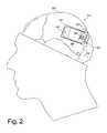
- FIG. 2is a schematic illustration of a patient's cranium showing the implantable neurostimulator of FIG. 1 as implanted, including leads extending to the patient's brain;
- FIG. 3is a schematic illustration of several regions of a patient's brain, including the hippocampus and parahippocampal gyrus;
- FIG. 4is a schematic sectional view of a patient's brain illustrating the placement of electrodes in the regions illustrated in FIG. 3 in one embodiment of the invention
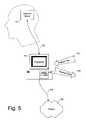
- FIG. 5is a block diagram illustrating context in which an implantable neurostimulator according to the invention is implanted and operated;
- FIG. 6is a block diagram illustrating the major subsystems of an implantable neurostimulator according to the invention.
- FIG. 7is a block diagram illustrating the components of the stimulation subsystem of the implantable neurostimulator shown in FIG. 6 ;
- FIG. 8is a block diagram illustrating the components of the measurement subsystem of the implantable neurostimulator shown in FIG. 6 ;
- FIG. 9is a flow chart illustrating the process performed in measuring the excitability of a region of a patient's brain in an embodiment of the invention.
- FIG. 10is a flow chart illustrating the process performed in testing an excitability level of a bran region in a system or method according to the process of FIG. 9 ;
- FIG. 11sets forth three graphs illustrating representative excitability response patterns identified by the process depicted in FIG. 9 ;
- FIG. 12is a flow chart illustrating the process performed in measuring the refractoriness of a region of a patient's brain in an embodiment of the invention
- FIG. 13is a flow chart illustrating the process performed in testing an inhibition level of a brain region in a system or method according to the process of FIG. 12 ;
- FIG. 14sets forth three graphs illustrating representative refractoriness response patterns identified by the process depicted in FIG. 11 ;
- FIG. 15is a flow chart illustrating the process performed in measuring an electrophysiological parameter in a patient's brain using a binary search method
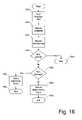
- FIG. 16is a flow chart illustrating a process by which excitability and refractoriness parameters can be used in determining whether to apply responsive treatment in a system and method according to the invention.
- FIG. 17is a flow chart illustrating a process by which excitability and refractoriness parameters, and short-term trends therein, can be used to control the mode of an implantable neurostimulator according to the invention.
- FIG. 1depicts an intracranially implanted device 110 according to the invention, which in one embodiment is a small self-contained responsive neurostimulator.
- a responsive neurostimulatoris a device capable of detecting ictal activity (or other neurological events) and providing therapy (often electrical stimulation) in response to that activity, where the therapy is specifically intended to terminate the ictal activity, treat a neurological event, or prevent an unwanted neurological event from occurring.
- the neurostimulatoris implanted intracranially in a patient's parietal bone 210 , in a location anterior to the lambdoidal suture 212 (see FIG. 2 ). It should be noted, however, that the placement described and illustrated herein is merely exemplary, and other locations and configurations are also possible, in the cranium or elsewhere, depending on the size and shape of the device and individual patient needs, among other factors.
- the device 110is preferably configured to fit the contours of the patient's cranium 214 .
- the device 110is implanted under the patient's scalp 112 but external to the cranium; it is expected, however, that this configuration would generally cause an undesirable protrusion in the patient's scalp where the device is located.
- the devicewhen it is not possible to implant the device intracranially, it may be implanted pectorally (not shown), with leads extending through the patient's neck and between the patient's cranium and scalp, as necessary.
- the embodiment of the device 110 described and illustrated hereinis preferably a responsive neurostimulator for detecting and treating epilepsy by detecting seizure precursors and preventing and/or terminating epileptic seizures.
- a primary function of a device according to the inventionis to detect any increased likelihood of the brain developing a seizure by identifying trends and conditions suggesting that increased likelihood, taking actions to prevent the seizure from occurring or terminate the seizure once it has begun, and using neurological conditions (including electrophysiological measurements) to specify or adjust the actions taken.
- the device 110is not a responsive neurostimulator, but is an apparatus capable of detecting neurological conditions and events and performing actions in response thereto.
- the actions performed by such an embodiment of the device 110need not be therapeutic, but may involve data recording or transmission, providing warnings to the patient, or any of a number of known alternative actions.
- Such a devicewill typically act as a diagnostic device when interfaced with external equipment, as will be discussed in further detail below.
- the device 110as implanted intracranially, is illustrated in greater detail in FIG. 2 .
- the device 110is affixed in the patient's cranium 214 by way of a ferrule 216 .
- the ferrule 216is a structural member adapted to fit into a cranial opening, attach to the cranium 214 , and retain the device 110 .
- a craniotomyis performed in the parietal bone anterior to the lambdoidal suture 212 to define an opening 218 slightly larger than the device 110 .
- the ferrule 216is inserted into the opening 218 and affixed to the cranium 214 , ensuring a tight and secure fit.
- the device 110is then inserted into and affixed to the ferrule 216 .
- the device 110includes a lead connector 220 adapted to receive one or more electrical leads, such as a first lead 222 .
- the lead connector 220acts to physically secure the lead 222 to the device 110 , and facilitates electrical connection between a conductor in the lead 222 coupling an electrode to circuitry within the device 110 .
- the lead connector 220accomplishes this in a substantially fluid-tight environment with biocompatible materials.
- the lead 222is a flexible elongated member having one or more conductors. As shown, the lead 222 is coupled to the device 110 via the lead connector 220 , and is generally situated on the outer surface of the cranium 214 (and under the patient's scalp 112 ), extending between the device 110 and a burr hole 224 or other cranial opening, where the lead 222 enters the cranium 214 and is coupled to a depth electrode (see FIG. 4 ) implanted in a desired location in the patient's brain.
- a depth electrodesee FIG. 4
- the burr hole 224is sealed after implantation to prevent further movement of the lead 222 ; in an embodiment of the invention, a burr hole cover apparatus is affixed to the cranium 214 at least partially within the burr hole 224 to provide this functionality.
- the device 110includes a durable outer housing 226 fabricated from a biocompatible material. Titanium, which is light, extremely strong, and biocompatible, is used in analogous devices, such as cardiac pacemakers, and would serve advantageously in this context. As the device 110 is self-contained, the housing 226 encloses a battery and any electronic circuitry necessary or desirable to provide the functionality described herein, as well as any other features. As will be described in further detail below, a telemetry coil may be provided outside of the housing 226 (and potentially integrated with the lead connector 220 ) to facilitate communication between the device 110 and external devices.
- the neurostimulator configuration described herein and illustrated in FIG. 2provides several advantages over alternative designs.
- the self-contained nature of the neurostimulatorsubstantially decreases the need for access to the device 110 , allowing the patient to participate in normal life activities. Its small size and intracranial placement causes a minimum of cosmetic disfigurement.
- the device 110will fit in an opening in the patient's cranium, under the patient's scalp, with little noticeable protrusion or bulge.
- the ferrule 216 used for implantationallows the craniotomy to be performed and fit verified without the possibility of damaging the device 110 , and also provides protection against the device 110 being pushed into the brain under external pressure or impact.
- a further advantageis that the ferrule 216 receives any cranial bone growth, so at explant, the device 110 can be replaced without removing any bone screws—only the fasteners retaining the device 110 in the ferrule 216 need be manipulated.
- the inventionis directed to the measurement of the patient's susceptibility to undesired neurological events through the analysis of brain electrophysiology, including excitability and refractoriness.
- An exemplary coronal section of a human brain 310is shown in FIG. 3 , which primarily shows a temporal lobe.
- the limbic systemis implicated in some cases of epilepsy.
- the normal human limbic systemis responsible for processing and regulating emotions, feelings, and moods.
- the hippocampus 312is a structure believed to be involved in memory and learning in humans.
- the parahippocampal gyrus 314which is also believed to be involved in long-term memory processes, is an external portion of the temporal lobe.
- the dentate gyrus 316is located between the hippocampus 312 and the parahippocampal gyrus 314 .
- the hypothalamus 318 and thalamus 320are portions of the brain located deep within the temporal lobe near the plane separating the two lateral hemispheres.
- the amygdala 322is located near the hippocampus 312 .
- Wilson articlesuggests that a perforant pathway (indicated by a representative arrow 324 that is not meant to indicate the actual path of neuronal communication) between the entorhinal cortex (of which the parahippocampal gyrus 314 forms a part) and the anterior portion of the hippocampus 312 is subject to hypersynchronous neuronal activity in a substantial number of epilepsy sufferers.
- the coronal brain section 310 of FIG. 3represents a functional illustration of several structures of the limbic system.
- the illustrated structuresin particular the hippocampus 312 and the parahippocampal gyrus 314
- the gross generalization of the limbic system pathways presented hereinis not a complete description of the functionality of the brain, the limbic system, or any portion thereof. It is intended to be illustrative of diagnosis, measurement, detection, and treatment options facilitated by the invention.
- the hippocampusincluding its anterior, middle, and posterior portions
- the presubicular cortexincluding its anterior, middle, and posterior portions
- the entorhinal cortexespecially the middle and posterior portions thereof
- the amygdalaThere are also believed to be various pathways implicating many other brain structures, including but not limited to the dentate gyrus 316 , the hypothalamus 318 , the thalamus 320 , the retrosplenial cortex, the paleocortex, the neocortex, the septal area, and the cingulated gyrus.
- the detection and measurement techniques of the present inventionmay be advantageously employed in connection with any or all of these pathways, as well as others, either between functionally distinct brain structures or within a single brain structure.
- hippocampal sclerosisparticularly found in the anterior hippocampus
- epilepsywhich in turn may affect (or be affected by) the electrophysiological characteristics of the associated pathways, so measurement and detection according to the invention would be advantageous in detecting and treating such deterioration.
- FIG. 4An electrode configuration capable of accomplishing this in conjunction with the invention is illustrated in FIG. 4 .
- a first depth lead 410is implanted in the patient's parahippocampal gyrus (PHG) 314 .
- the first depth lead 410which is used to electrically stimulate the PHG 314 , includes a first conductive electrode 412 placed in contact with brain tissue in the PHG 314 ; the remainder of the surface of the first depth lead is insulating.
- the first conductive electrode 412is in communication with electronic circuitry in the device 110 by a conductor in the first depth lead 410 .
- a second depth lead 414is implanted in the patient's hippocampus 312 .
- the second depth lead 414which is used to sense responses to stimulation provided by the first electrode 412 , includes a second conductive electrode 416 and preferably a third conductive electrode 418 to facilitate bipolar sensing placed in contact with brain tissue in the hippocampus 312 .
- the remainder of the second depth lead 414is insulating, but internal conductors connect the device 110 to the second and third conductive electrodes 416 and 418 .
- the depth leads 410 and 414are primarily fabricated from a durable biocompatible insulating material, such as a silicone elastomer.
- the conductive electrodes 412 , 416 , and 418may be a platinum/iridium alloy, pure platinum, or iridium oxide, all of which are conductive biocompatible materials suitable for use as implanted electrodes.
- the first depth lead 410has a single conductive electrode 412 and the second depth lead 414 has two conductive electrodes 416 and 418 .
- additional conductive electrodesat or near the distal end of each depth lead, each individually connected to the device 110 by a separate conductor in the corresponding lead (such as the lead 222 ).
- Such a configurationwould provide multiple stimulation or sensing options in each region of the brain; it might also be possible to perform stimulation and sensing with a single depth lead, provided conductive electrodes are located appropriately along a single line of approach.
- the depth leadsare implanted by first forming an opening in the cranium, typically a burr hole (such as the burr hole 224 of FIG. 2 ).
- the depth leadsare stereotactically inserted through a cannula (with the assistance of a stylet to provide additional rigidity).
- a styletto provide additional rigidity.
- temporal lobe epilepsyis often characterized by hypersynchronous neuronal discharges originating in the temporal lobe.
- the hippocampus 312 , PHG 314 , and other structures of the limbic systemmay have a role in this; they also may have a role in normal long-term memory, emotions, feelings, and moods.
- a neurostimulatoroperates in conjunction with external equipment.
- the device 110is mostly autonomous (particularly when performing its usual measurement, detection, and stimulation capabilities), but preferably includes a selectable part-time wireless link 510 to external equipment such as a programmer 512 .
- the wireless link 510is established by moving a wand (or other apparatus) having communication capabilities and coupled to the programmer 512 into range of the device 110 .
- the programmer 512can then be used to manually control the operation of the device 110 , as well as to transmit information to or receive information from the device 110 .
- the programmer 512is capable of performing a number of advantageous operations in connection with the invention.
- the programmer 512is able to specify and set variable parameters in the device 110 to adapt the function of the device 110 to meet the patient's needs, download or receive data (including but not limited to stored EEG waveforms, parameters, or logs of actions taken) from the device 110 to the programmer 512 , upload or transmit program code and other information from the programmer 512 to the device 110 , or command the device 110 to perform specific actions or change modes as desired by a physician operating the programmer 512 .
- the programmer 512is adapted to receive physician input 514 and provide physician output 516 ; data is transmitted between the programmer 512 and the device 110 over the wireless link 510 .
- the programmer 512may be coupled via a communication link 518 to a network 520 such as the Internet.
- a network 520such as the Internet.
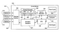
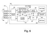
- FIG. 6An overall block diagram of the device 110 used for measurement, detection, and treatment according to the invention is illustrated in FIG. 6 .
- the control module 610is capable of being coupled to a plurality of electrodes 612 , 614 , 616 , and 618 (each of which may be connected to the control module 610 via a lead that is analogous or identical to the lead 222 of FIG. 2 ) for sensing and stimulation.
- the couplingis accomplished through the lead connector 220 ( FIG. 2 ). Although four electrodes are shown in FIG.
- the electrodes 612 – 618are connected to an electrode interface 620 .
- the electrode interfaceis capable of selecting each electrode as required for sensing and stimulation; accordingly the electrode interface is coupled to a sensing subsystem 622 and a stimulation subsystem 624 .
- the electrode interfaceis also may provide any other features, capabilities, or aspects, including but not limited to amplification, isolation, and charge-balancing functions, that are required for a proper interface with neurological tissue and not provided by any other subsystem of the device 110 .
- the sensing subsystem 622includes an EEG analyzer function 626 and an electrophysiology (EP) analyzer function 628 .
- the EEG analyzer function 626is adapted to receive EEG signals from the electrodes 612 – 618 , through the electrode interface 620 , and to process those EEG signals to identify neurological activity indicative of a seizure or a precursor to a seizure.
- EEG analysis functionalityis disclosed in detail in U.S. Pat. No. 6,016,449 to Fischell et al., incorporated by reference above.
- the EP analysis functionality of the inventionis described in further detail below, particularly in connection with FIGS. 9–17 .
- the sensingmay optionally also contain further sensing and detection capabilities, including but not limited to parameters derived from other physiological conditions (such as temperature, ECG, blood pressure, etc.).
- the stimulation subsystem 624is capable of applying electrical stimulation to neurological tissue through the electrodes 612 – 618 . This can be accomplished in any of a number of different manners. For example, it may be advantageous in some circumstances to provide stimulation in the form of a substantially continuous stream of pulses. Preferably, therapeutic stimulation is provided in response to abnormal events detected by the EEG analyzer function 626 of the sensing subsystem 622 . As illustrated in FIG. 6 , the stimulation subsystem 624 and the EEG analyzer function 626 are connected; this facilitates the ability of stimulation subsystem 624 to provide responsive stimulation as well as an ability of the sensing subsystem 622 to blank the amplifiers while stimulation is being performed to minimize stimulation artifacts. It is contemplated that the parameters of the stimulation signal (e.g., frequency, duration, waveform) provided by the stimulation subsystem 624 would be specified by other subsystems in the control module 610 , as will be described in further detail below.
- the parameters of the stimulation signale.g., frequency, duration, waveform
- the EP analyzer function 628is also in communication with the stimulation subsystem 624 .
- the electrophysiological measurement capabilities of the inventionare active and dependent upon analysis of responses to particular stimulation signals provided by the device 110 ; the link between the EP analyzer 628 and the stimulation subsystem 624 enables this functionality.
- a memory subsystem 630 and a central processing unit (CPU) 632which can take the form of a microcontroller.
- the memory subsystemis coupled to the sensing subsystem 622 (e.g., for receiving and storing data representative of sensed EEG signals and evoked responses), the stimulation subsystem 624 (e.g., for providing stimulation waveform parameters to the stimulation subsystem), and the CPU 632 , which can control the operation of the memory subsystem 630 .
- the CPU 632is also connected to the sensing subsystem 622 and the stimulation subsystem 624 for direct control of those subsystems.
- the communication subsystem 634enables communication between the device 110 ( FIG. 1 ) and the outside world, particularly the external programmer 512 ( FIG. 5 ).
- the disclosed embodiment of the communication subsystem 634includes a telemetry coil (which may be situated outside of the housing 226 ) enabling transmission and reception of signals, to or from an external apparatus, via inductive coupling.
- Alternative embodiments of the communication subsystem 634could use an antenna for an RF link or an audio transducer for an audio link.
- the power supply 636supplies the voltages and currents necessary for each of the other subsystems.
- the clock supply 638supplies substantially all of the other subsystems with any clock and timing signals necessary for their operation.
- control module 610is preferably a single physical unit contained within a single physical enclosure, namely the housing 226 ( FIG. 2 ), it may comprise a plurality of spatially separate units each performing a subset of the capabilities described above.
- various functions and capabilities of the subsystems described abovemay be performed by electronic hardware, computer software (or firmware), or a combination thereof.
- the division of work between the CPU 632 and the other functional subsystemsmay also vary—the functional distinctions illustrated in FIG. 6 may not reflect the integration of functions in a real-world system or method according to the invention.
- FIG. 7The various functions and capabilities of the stimulation subsystem 624 are illustrated in greater detail in FIG. 7 . Consistent with FIG. 6 , inputs to the stimulation subsystem 624 are shown on the right, and outputs are on the left.
- the stimulation subsystem 624includes a control interface 710 , which receives commands, data, and other information from the CPU 632 , the memory subsystem 630 , and the sensing subsystem 622 .
- the control interface 710uses the received commands, data, and other information to control a therapeutic stimulator 712 , a sensory stimulator 714 , and a diagnostic stimulator 716 .
- the therapeutic stimulator 712is adapted to provide electrical stimulation signals appropriate for application to neurological tissue to terminate a present or predicted undesired neurological event, especially an epileptic seizure (or its precursor).
- the therapeutic stimulator 712is typically activated in response to conditions detected by the sensing subsystem 622 , but may also provide some substantially continuous stimulation.
- the sensory stimulator 714is also typically activated in response to a detection by the sensing subsystem; it may electrically stimulate enervated tissue (such as the scalp) to provide a tactile sensation to the patient, or may alternatively include an audio or visual transducer to provide audiovisual cues (such as warnings) to the patient.
- the diagnostic stimulator 716includes two sub-functions, an excitability stimulator 718 and a refractoriness stimulator 720 , though both functions may be performed by the same circuit under differing controls from the control interface 710 .
- the excitability stimulator 718 and the refractoriness stimulator 720both act under the control of the sensing subsystem 622 to provide the stimulation signals necessary for the effective measurement of electrophysiological parameters according to the invention.
- the excitability stimulator 718provides pulses at varying current levels to test the excitability of neural tissue (see FIGS. 9–11 , described below), while the refractoriness stimulator 720 provides pairs of pulses with varying inter-pulse intervals to test the inhibitory characteristics of neural tissue (see FIGS. 12–14 , described below).
- the therapeutic stimulator 712 , the sensory stimulator 714 , and the diagnostic stimulator 716are all coupled to a multiplexer 722 , which is controllable to select the appropriate types of stimulation and pass them along to a stimulation signal generator 724 .
- the multiplexer 722may allow only one type of stimulation to be performed at a time, but in a presently preferred embodiment, the multiplexer 722 allows different types of stimulation to be selectively applied to the different electrodes 612 – 618 , either sequentially or substantially simultaneously.
- the stimulation signal generator 724receives commands and data from the therapeutic stimulator 712 , the sensory stimulator 714 , and the diagnostic stimulator 716 , and generates electrical stimulation signals having the desired characteristics that are properly time-correlated and associated with the correct electrodes, and receives power from a controllable voltage multiplier 726 to facilitate the application of a proper voltage and current to the desired neurological tissue.
- the voltage multiplier 726is capable of creating relatively high voltages from a battery power source, which typically has a very low voltage; circuits to accomplish this function are well known in the art of electronics design.
- the stimulation signal generator 724has a plurality of outputs 728 , which in the disclosed embodiment are coupled to the electrode interface 620 ( FIG. 6 ). In various embodiments of the invention, the stimulation signal generator 724 can perform signal isolation, multiplexing, and queuing functions if the electrode interface 620 does not perform such functions.
- FIG. 7it should be recognized that while various functional blocks are illustrated in FIG. 7 , not all of them might be present in an operative embodiment of the invention. Furthermore, as with the overall block diagram of FIG. 6 , the functional distinctions illustrated in FIG. 7 , which are presented as separate functions for clarity and understandability herein, might not be meaningful distinctions in an implementation of the invention.
- the various stimulation typesare all accomplished with a single circuit selectively controlled with different parameters; there is a single controllable stimulator capable of selectively providing signals for therapeutic stimulation, diagnostic stimulation, and sensory stimulation.
- FIG. 8illustrates details of the sensing subsystem 622 ( FIG. 6 ). Inputs from the electrodes 612 – 618 are on the left, and connections to other subsystems are on the right.
- the electrode selector 810allows the device to select which electrodes (of the electrodes 612 – 618 ) should be routed to which individual channels of the sensing subsystem 622 , based on control received through a control interface 818 from the memory subsystem 630 or the CPU 632 ( FIG. 6 ).
- the electrode selector 810provides signals corresponding to each selected electrode (of the electrodes 612 – 618 ) to a bank of differential amplifiers 812 , which are gain-matched and adapted to amplify the input signals to a level capable of being processed by a system or method according to the invention.
- the bank of differential amplifiers 812includes a plurality of channels; each channel receives a pair of electrode signals from the electrode selector 810 and amplifies the difference in potential between them to derive an analog input signal representative of the bipolar signal between two selected electrodes.
- the bank of amplifiers 812transmits the amplified analog input signals to a bank of analog-to-digital converters (ADCs) 814 , which generates a number of digital signals corresponding to the analog input signals. These digital signals are passed to a multiplexer 816 , which interleaves the digital signals. The multiplexed input signal is then fed from the multiplexer 816 to a signal processor 820 .
- ADCsanalog-to-digital converters
- FIG. 8illustrates the multiplexer 816 placed between the bank of ADCs 814 and the signal processor 820
- a multiplexing functioncan be performed between the electrode selector 810 and the bank of differential amplifiers 812 (which, in this embodiment, would be a single amplifier), or between the differential amplifiers 812 and the ADCs 814 (in this embodiment, a single ADC).
- the multiplexer 816 before the ADC 814would enable the use of a single ADC for multiple input channels, but requires a high speed ADC that may require more current to operate. This can be avoided by locating the multiplexer 816 after a bank of ADCs, as suggested above, but one low power ADC would then be required for each input channel.
- the signal processor 820is preferably a special-purpose digital signal processor (DSP) adapted for use with the invention, or in an alternative embodiment, may comprise a programmable general-purpose DSP.
- the signal processorhas its own scratchpad memory area 822 used for local storage of data and program variables when the signal processing is being performed. In either case, the signal processor performs the measurement and detection methods set forth in FIGS. 9–17 , described below. Any results from such methods, as well as any digitized signals intended for storage transmission to external equipment, are passed to various other subsystems of the control module 610 , including the memory subsystem 630 and the CPU 632 ( FIG. 6 ) through a data interface 824 .
- DSPdigital signal processor
- the method of measuring excitability of neural tissue as performed by the EP analyzer 628 of the sensing subsystem 622 (in connection with the stimulation subsystem 624 )is illustrated in the form of a flow chart in FIG. 9 .
- the device 110FIG. 1
- the measurement of electrophysiological parameters according to the inventionis preferably not performed continuously, so until a measurement of excitability is called for (either on a scheduled, commanded, or responsive basis), the method of measuring excitability begins by awaiting a start signal (step 910 ).
- the memory subsystem 630is queried for the existence of a baseline, or expected, excitability value (step 912 ).
- the baseline excitability valueif one exists, can be selected from previously measured values, preferably at a comparable time of day (or with the patient in a comparable state of alertness), or from a programmed selected value, which also may be time-dependent.
- the baseline excitability valueis stored in the memory subsystem 630 by the external programmer 512 .
- the patient's physiciancommands the device 110 (via the programmer 512 ) to perform a sequence of excitability measurements by the methods set forth below; the resulting waveforms, rather than being automatically analyzed by the device, are downloaded to the programmer 512 for consideration by the physician.
- the physiciancan then select the results most representative of an excitatory response, and program the parameters of that response into the device for future automatic use as a baseline threshold value. This procedure can be performed several times, at various times of day, to give the physician multiple options in choosing appropriate parameters, and to account for diurnal cyclical variation in excitability, as described below.
- a linear searchis performed for the excitability value.
- the searchbegins by setting an initial pulse amplitude (in current) to, for example, 1 mA (step 914 ). This is a lower bound value that is not expected to trigger neural excitation as determined by the physician by commanding the test manually.
- the neural tissue excitabilityis then tested at the pulse amplitude (step 916 ) by applying an electrical stimulating pulse to an electrode implanted at a stimulation site and measuring the response in another electrode implanted at a measurement site (see FIG. 4 ).
- Excitabilityis verified by measuring the peak amplitude of any responsive signal received by the electrode implanted at the measurement site. If there is an excitatory response, there will be a significant waveform amplitude of the measured response signal (especially if a number of trials are averaged, where such number is preferably two to four) in comparison to measurements taken below the excitability threshold.
- the response signalcan be assigned a threshold as a percentage of the stimulation amplitude, or as a static programmed value.
- the threshold for verifying that a response occurredmay either be set as fixed value determined by commanding the test under physician control, or by setting an adaptive threshold above the averaged baselined EEG signal. Further techniques for identifying evoked responses will be described below.
- step 918If a response is detected (step 918 ), the neural tissue being measured is excitable at the amplitude being tested, and the process of searching for an excitability threshold is finished (step 920 ). Otherwise, a delay (which can typically range from 15 seconds to 30 minutes) is taken to allow the neural tissue to recover from any effects of the most recent excitability test pulse (step 922 ), and to allow any inhibitory response to diminish, the amplitude is incremented by 1 mA (step 924 ), or some other user selectable increment, and the method repeats by testing excitability again at the new amplitude (step 916 ).
- a delaywhich can typically range from 15 seconds to 30 minutes
- a bounds checking stepwould be advantageous; once the amplitude reaches a predetermined upper level, the method should be terminated even if excitability has not been detected.
- steps 914 and 924 aboveindicate that amplitude should start at 1 mA and be incremented in steps of 1 mA, those numbers are for purposes of illustration only and any sufficiently low starting amplitude and suitable step size, uniform or not, would be appropriate.
- step 912If a baseline value is available (step 912 ) when the method begins, there is no need to test the entire range of amplitudes. Rather, the initial amplitude is set to the expected baseline value plus a delta (step 926 ), wherein the delta is half of the smallest acceptable resolution interval. The excitability is then tested at the initial amplitude (step 928 ). If a response is not detected (step 930 ), then the initial amplitude is below the excitability threshold, and after a delay (step 922 ), the amplitude is incremented (step 924 ) and another measurement is taken.
- step 930if a response is detected (step 930 ), the initial amplitude is above the excitability threshold, so after a delay (step 932 ) the amplitude is decremented (step 934 ) and excitability is tested again (step 936 ).
- the methodcontinues by delaying (step 932 ) and decrementing (step 934 ) if a response continues to be detected (step 938 ). Once a response is no longer detected (step 938 ), the method is complete (step 940 ).
- an excitability threshold valuemay be calculated as the average of the foregoing two amplitudes, or may just be taken as the lowest stimulation value that resulted in a response.
- the expected baseline values used by the methodcan be set by the patient's physician or can represent historical information.
- Excitabilityexhibits diurnal cyclical variability, and tends to vary between when the patient is sleeping and when the patient is awake.
- any baseline value usedshould take into account this cyclical behavior, for example by taking a moving average of time-correlated values over the last several (e.g., five) days (or fewer if any day in that period has a previously-identified abnormal excitability measurement).
- There are other approaches to tracking historical excitability informationthat would also be expected to provide advantageous results; for example, if the device 110 ( FIG. 1 ) includes the capability of determining whether the patient is asleep, that data might be used to index the expected excitability threshold.
- FIG. 10illustrates the steps performed in acquiring an individual excitability measurement at a specified amplitude, as in steps 916 , 928 , and 936 of FIG. 9 .
- excitabilityis measured at the same amplitude four times in sequence and the resulting signals are summed and averaged—any evoked responses will tend to reinforce each other, while noise and other background signals contribute less to the aggregate.
- the number of remaining loopsis initially set to four (step 1010 ).
- the neural tissue to be testedis then stimulated with a single pulse (preferably charge-balanced) at the selected amplitude (step 1012 ).
- the charge-balanced pulse applied at this stephas a constant current, and a duration of approximately 300 ⁇ s per phase (for a total duration of approximately 600 ⁇ s), but other pulse configurations are possible. It has been found to be advantageous to perform the excitability tests herein with stimulation current as the variable parameter. Voltage will vary depending on the impedance of the leads and the neurological tissue in the stimulation circuit.
- Any responseis then received (step 1014 ) and recorded (step 1016 ).
- the number of remaining loopsis decremented (step 1018 ), and if there are any iterations remaining (step 1020 ), a delay is taken (step 1022 ) to allow any inhibitory response to diminish and the stimulation and measurement steps are performed again (steps 1012 – 1016 ).
- a sufficient delayis provided between each iteration to ensure that there is no inhibitory or other effect from the preceding stimulus when the next stimulus is applied. This delay may be varied according to a pattern or at random to reduce the possibility of results skewed by acclimation or long term potentiation.
- the stored responsesare averaged (step 1024 ) and the measurement is complete (step 1026 ).
- evoked responsesare separated from noise by averaging over multiple stimuli.
- Averaging over four loopswill generally provide an acceptable signal to noise ratio for the substantially unambiguous determination of evoked responses when implanted deep brain electrodes are appropriately located and used in accordance with the invention, but it should be noted that a smaller number may be adequate, or a larger number may be necessary depending on the circumstances.
- FIG. 11illustrates several exemplary stimulation pulses applied as described in the excitability test procedure detailed above.
- FIG. 11Aillustrates a first stimulation signal 1110 that comprises a charge-balanced pulse having an amplitude of 2 mA; that pulse is applied to a stimulation electrode implanted at a desired stimulation site.
- the stimulation electrodewould be implanted in the parahippocampal gyrus (PHG) 314 ( FIG. 3 ).
- PEGparahippocampal gyrus
- a first responsive signal 1112is received with a measurement electrode implanted at a desired measurement site, which in one embodiment of the invention is the hippocampus 312 .
- the first responsive signal 1112(which in the figure has substantially no noise, and can be considered an average response over multiple stimuli) exhibits a relatively small deviation occurring after the first stimulation signal 1110 .
- This deviation in the first responsive signal 1112is very small, and does not represent a physiological response (merely a filtered transmission of the original first stimulation signal 1110 ), so the amplitude of 2 mA is deemed to be below the excitability threshold.
- FIG. 11Billustrates a second stimulation signal 1114 ; this signal comprises a pulse with an amplitude of 4 mA.
- the second responsive signal 1116is similar to the first responsive signal 1112 , so the stimulation amplitude of 4 mA is also deemed to be below the excitability threshold.
- FIG. 11Cillustrates a third stimulation signal 1118 ; this signal comprises a pulse with an amplitude of 6 mA.
- the third responsive signal 1120is of a different character than the previous two responsive signals 1116 and 1112 .
- the third responsive signal 1120is characterized by a first deviation 1122 , a second deviation 1124 , and a third deviation.
- the first deviationis similar to the deviations exhibited in the other two sub-threshold responsive signals 1112 and 1116 , and is believed to represent a filtered transmission of the stimulation pulse.
- the second deviation 1124represents an excitatory response—it is greater in amplitude than either the first deviation 1122 or any characteristic of the other responsive signals 1112 and 1116 .
- the second deviation 1124is the characteristic that identifies the third responsive signal 1120 as an evoked response, which identifies the stimulation amplitude of 6 mA as above the excitability threshold.
- the excitability thresholdis hence between 4 mA and 6 mA, so a calculated figure of 5 mA is used for purposes of the invention.
- the third responsive signal 1120as illustrated in FIG. 11C , is representative of what a certain excitatory response waveform may look like. However, note that other types of responses are also possible, which may or may not look significantly like the waveform of FIG. 11C . However, the principles set forth above should continue to apply. To identify an excitatory evoked response, it is necessary to look beyond the existence of a deviation in the responsive signal.
- noisedoes not refer solely to electromagnetic interference received from external sources—it also includes any EEG signal not directly evoked by or related to the preceding stimulus pulse.
- “noise” for purposes of this system and methodcan include, among other things, EEG signals representative of normal brain activity.
- one method for determining whether a measured response is representative of an electrophysiological evoked responseinvolves physician interaction.
- a physiciancauses the device 110 to perform a sequence of excitability tests at various amplitudes.
- the responses to those testsare stored as necessary and transmitted to the programmer 512 via the communication subsystem 634 .
- the programmerallows the physician to view each response and visually ascertain which ones, if any, represent excitatory responses.
- a representative excitatory responseis then selected by the physician for use as a template and transmitted back to the device 110 . Accordingly, then, in the method set forth in FIGS.
- each time a response is analyzedit can be compared to the representative excitatory response to determine whether a particular response represents neural excitation. This approach is more computationally intensive, but potentially more accurate, than simply comparing each response to a threshold as described above.
- This template comparison operationis preferably performed by scaling the measured response (or the template) so the measured response and the template substantially match in amplitude and duration, and thereafter quantifying any difference between the two signals. If the difference exceeds a predetermined (or programmed) threshold, then the measured response and the template do not match, and there has been no excitatory response. If the threshold is not exceeded, then the measured response and the template substantially match, indicating an excitatory response.
- Template matchingcan be performed by comparing amplitude on a sample-by-sample basis, or preferably is accomplished by decomposing both the template and the measured response into features, such as half waves or line segments, and comparing the attributes of the appropriate features.
- the complementary operationcan also be performed.
- the physiciancan identify a representative non-excitatory response, and program that as a template. In the absence of other factors, any measured response that matches the template is also most likely non-excitatory, and any measured response that does not match the template is most likely excitatory.
- FIG. 12illustrates the method used to measure the refractoriness of neural tissue in a particular pathway according to the invention.
- “refractoriness” of a neural pathwayis an indication of how long it takes the neurons in the pathway to recover from a previous stimulation. Typically, after a neural pathway is excited, it takes some time for the pathway to recover and become able to exhibit another response. The length of this post-excitation period, in which a response in the pathway is inhibited, is the refractoriness parameter desired to be measured.
- the methodbegins by awaiting a start signal (step 1210 ), during which time the device 110 ( FIG. 1 ) can be performing other operations, including other measurement, detection, and stimulation operations.
- the baseline refractoriness valueis stored in the memory subsystem 630 by the external programmer 512 .
- the patient's physiciancommands the device 110 (via the programmer 512 ) to perform a sequence of refractoriness measurements by the methods set forth below; the resulting waveforms, rather than being automatically analyzed by the device, are downloaded to the programmer 512 for consideration by the physician.
- the physiciancan then select the results most representative of an uninhibited response, and program the parameters of that response into the device for future automatic use as a baseline threshold value. This procedure can be performed several times, at various times of day, to give the physician multiple options in choosing appropriate parameters, and to account for diurnal cyclical variation in refractoriness.
- baseline values for refractorinesscan be obtained by comparing measurements in a patient's sclerotic region to measurements from non-sclerotic analogous structures in the other hemisphere, subject to the limitations set forth above with regard to excitability.
- measurement via a linear search techniquebegins by setting an initial inter-pulse interval to 50 ms (step 1214 ).
- the inhibition characteristics of the desired neural tissueare then tested by applying a pair of pulses with the desired inter-pulse interval (step 1216 ).
- Each pulse in the pairis of an amplitude that exceeds the excitability threshold (as determined above).
- the first pulse in the pair of pulsescauses an excitatory evoked response; whether the second pulse causes a similar response depends on whether the inter-pulse delay exceeds an inhibition period, which is the parameter sought to be identified.
- an excitatory response in connection with the second pulseis what the present method is intended to identify, and as above (See FIG. 11 ), the existence of a second deviation in a responsive signal is indicative.
- This measurement methodwill be set forth in further detail below in connection with FIGS. 13–14 .
- step 1218If a second excitatory response is detected (step 1218 ), the inhibition period has been exceeded and the method is complete (step 1220 ). Otherwise, a delay is taken (step 1222 ) to allow the stimulated tissue to recover from its inhibitory behavior, the inter-pulse interval is incremented by 50 ms (step 1222 ), and inhibition is tested again (step 1216 ).
- the initial inter-pulse intervalis set to 50 ms by step 1214 and is incremented 50 ms at a time by step 1224 , it should be recognized that any desired starting interval and increment value, whether or not uniform, can be used with similar results, but will change the resulting resolution and the time required to perform a measurement. Also, it would be beneficial to implement an upper bound to the incrementation performed in step 1222 , in case a second response is never detected.
- the initial inter-pulse intervalis set to the baseline value plus a delta (step 1226 ).
- the deltais equal to half the desired resolution (or increment value used in step 1224 ).
- the inhibition periodis tested using the initial inter-pulse interval (step 1228 ). If a second response is not detected (step 1230 ), then the inter-pulse interval is shorter than the inhibition period, and after a delay (step 1222 ), the interval is incremented (step 1224 ) and inhibition is tested again (step 1216 ).
- step 1230If, on the other hand, a second response is detected (step 1230 ), then the inter-pulse interval exceeds the inhibition period, and after a delay (step 1232 ), the interval is decremented (step 1234 ), and inhibition is again tested (step 1236 ). If a second response is then detected (step 1238 ), the method is finished (step 1240 ). Otherwise, there is another delay (step 1232 ), and the inter-pulse interval is decremented (step 1234 ) and tested again (step 1236 ).
- the inhibition periodhas been identified as somewhere between the most recent measurement at which there was no second response and the most recent measurement at which there was a second response. Accordingly, a measured inhibition period value is calculated as the average of the preceding two measurements.
- the expected baseline values used by the methodcan be set by the patient's physician or can represent historical information. Like excitability, it is believed that refractoriness may exhibit diurnal cyclical variability. To reduce the possibility of misleading inhibition period measurements, any baseline value used should take into account this cyclical behavior, for example by taking a moving average of time-correlated values over the last several (e.g., five) days (or fewer if any day in that period has a previously-identified abnormal measurement). And as above, there are other approaches to tracking historical inhibition information that would also be expected to provide advantageous results; for example, if the device 110 ( FIG. 1 ) includes the capability of determining whether the patient is asleep, that data might be used to index the expected baseline inhibition period.
- FIG. 13illustrates the method performed in taking a single measurement of the inhibition period of neurological tissue at a desired inter-pulse interval, as in steps 1216 , 1228 , and 1236 of FIG. 12 .
- four iterationsare performed to provide sufficient signal to noise ratio for the substantially unambiguous identification of evoked responses.
- the methodbegins by setting a loop counter to four (step 1310 ).
- a primary charge-balanced stimulation pulseis then applied (step 1312 ).
- the primary stimulation pulsehas an amplitude sufficient to evoke an excitatory response (as determined above, or as previously programmed), and a known duration (e.g., 300 ⁇ s per phase, as above). The response to this pulse is not preserved.
- a delay corresponding to the desired inter-pulse intervalis then observed (step 1314 ), and a secondary charge-balanced stimulation pulse is applied (step 1316 ).
- the secondary stimulation pulsepreferably has parameters substantially equal to those of the primary stimulation pulse. Any evoked response is then received (step 1318 ) and stored (step 1320 ).
- the loop counteris decremented (step 1322 ), and if there are any iterations remaining (step 1324 ), a delay sufficient to reduce any remaining inhibitory response is performed (step 1326 ).
- a sufficient delayis provided between each iteration to ensure that there is no inhibitory or other effect from the preceding stimulus when the next stimulus is applied. This delay may be varied according to a pattern or at random to reduce the possibility of results skewed by acclimation or long term potentiation.
- the stored responsesare averaged (step 1328 ) and the measurement is complete (step 1330 ).
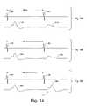
- FIG. 14illustrates representative waveforms potentially observed in several inhibition period measurements performed according to the method of FIG. 13 .
- a primary stimulation pulse 1410(having an amplitude sufficient to evoke an excitatory response) is applied to a stimulation electrode implanted at a stimulation site, followed after an inter-pulse delay of 200 ms by a secondary stimulation pulse 1412 applied to the same stimulation site.
- a primary response 1414representative of excitation, is received at a sensing electrode implanted at a measurement site after the primary stimulation pulse 1410
- a secondary response 1416is received at the sensing electrode after the secondary stimulation pulse 1412 .
- FIGS. 14Like the responses illustrated in FIGS.
- the secondary response 1416is not representative of a physiological evoked response, only a filtered transmission of the secondary stimulation pulse 1412 . Accordingly, the inter-pulse delay of 200 ms is shorter than the inhibition period, and the secondary response 1416 has been inhibited.
- FIG. 14BA similar situation is illustrated in FIG. 14B .
- a primary stimulation pulse 1418is applied, followed by a secondary stimulation pulse 1420 after an inter-pulse delay of 400 ms.
- a primary response 1422is excitatory, but the secondary response 1424 is primarily inhibited.
- a primary stimulation pulse 1428is followed by a secondary stimulation pulse 1430 after an inter-pulse delay of 800 ms.
- Both the primary response 1432 and the secondary response 1434are excitatory, indicating that the inhibition period has been exceeded by the inter-pulse interval.
- a substantial second deviation 1436 in the secondary response 1434is indicative of the excitatory response.
- the form of an excitatory responsemay vary depending on the neural pathway or the type of neural tissue being examined, among numerous other factors. In any event, there is expected to be a signal perturbation adequate for analysis and identification by an implanted self-contained measurement system according to the invention.
- a method for determining whether a measured response is representative of an electrophysiological evoked responseinvolves physician interaction.
- a physiciancauses the device 110 to perform a sequence of refractoriness tests at various inter-pulse intervals.
- the responses to those testsare stored as necessary and transmitted to an external apparatus via the communication subsystem 634 .
- the external apparatuswhich preferably is a programmer adapted to receive and display information from the device 110 , allows the physician to view each response and visually ascertain which ones, if any, represent uninhibited responses.
- a representative uninhibited responseis then selected by the physician for use as a template and transmitted back to the device 110 . Accordingly, then, in the method set forth in FIGS. 12–13 , each time a response is analyzed, it can be compared to the representative uninhibited response to determine whether a particular response represents inhibition.
- the template comparison operationis preferably performed by scaling the measured response (or the template) so the measured response and the template substantially match in amplitude and duration, and thereafter quantifying any difference between the two signals. If the difference exceeds a predetermined (or programmed) threshold, then the measured response and the template do not match, and there has been no uninhibited response. If the threshold is not exceeded, then the measured response and the template substantially match, indicating an uninhibited response.
- Template matchingcan be performed by comparing amplitude on a sample-by-sample basis, or preferably is accomplished by decomposing both the template and the measured response into features, such as half waves or line segments, and comparing the attributes of the appropriate features.
- a complementary operationcan also be performed.
- the physiciancan identify a representative inhibitory response, and program that as a template. In the absence of other contributing factors, any measured response that matches the template is also most likely inhibitory, and any measured response that does not match the template is most likely uninhibited.
- templatescan be used to address different electrode combinations or different expected baselines (e.g., depending on the time of day). However, if most or all expected responses are similar in their features, it should be observed that multiple templates need not be used; a generalized template can be created by the physician via the programmer and used in multiple electrophysiological parameter measurement scenarios.
- FIG. 15proceeds as follows. The method begins, once again, by awaiting a start signal (step 1510 ), during which time other functions can be performed by the device 110 ( FIG. 1 ).
- the memory subsystem 630( FIG. 6 ) is queried for the existence of a baseline excitability value (step 1512 ), which in the disclosed embodiment is stored in the memory subsystem 630 after having been received from the programmer 512 ( FIG. 5 ). If one is not available, the method proceeds by selecting appropriate lower and upper bounds, and setting a range bottom and a range top accordingly (step 1514 ). For purposes of testing excitability according to the invention, it may be appropriate to set the range bottom to 1 mA and the range top to 10 mA.
- the middle pointis then calculated as an arithmetic average of the range top and the range bottom (step 1516 ); this average middle point is then used as the amplitude for performing the excitability test (in the same manner illustrated in FIG. 10 ), and accordingly, the excitability is tested (step 1518 ) at the middle.
- step 1520If an excitatory response is detected (step 1520 ), the excitability threshold must be in the lower half of the range, so the range bounds are adjusted so the new range top is equal to the tested middle point (step 1522 ). If no excitatory response is detected (step 1520 ), the excitability threshold must be in the upper half of the range, so the range bounds are adjusted so the new range bottom is equal to the tested middle point (step 1524 ). The difference between the range bottom and the range top is tested to determine whether it is smaller than a desired resolution (step 1526 ). If so, the measured excitability threshold is deemed to be the middle of the range and the process is finished (step 1528 ). Otherwise, a delay is performed to eliminate any lingering inhibitory or other effects (step 1530 ), a new middle point is calculated (step 1516 ) and the process continues.
- the testing rangeis defined to accommodate it.
- the range bottomis defined to be the baseline value minus half of the desired resolution
- the range topis defined to be the baseline value plus half of the desired resolution (step 1532 ). Accordingly, if the excitability threshold is determined to be within this range, no further testing need be performed. So the excitability is first tested at the range bottom (step 1534 ).
- the excitability thresholdis somewhere below the current range bottom, so after a delay to allow any remaining inhibitory response to diminish (step 1538 ), a new range top is set to the tested range bottom (which was determine to be higher than the threshold), and a new range bottom is set to the lower limit, in the disclosed embodiment 1 mA. A new midpoint is then calculated (step 1516 ) and the binary search continues.
- step 1542If no response was detected, a delay is performed (step 1542 ), and excitability is tested at the top of the existing range (step 1544 ). If a response is detected (step 1546 ), then the excitability threshold is deemed to be halfway between the bottom of the range and the top of the range, and the resolution requirement has been met, so the measurement is finished (step 1548 ). Otherwise, the excitability threshold must be greater than the top of the existing range. So another delay is performed (step 1550 ), the range is adjusted (step 1552 ) so the new range bottom is equal to the existing range top, and a new range bottom is set to the upper limit, which in the disclosed embodiment is 10 mA. A new midpoint is selected (step 1516 ), and the binary search continues.
- a similar processis performed for refractoriness.
- a start signalis awaited (step 1510 ), during which time other functions can be performed by the device 110 ( FIG. 1 ).
- the memory subsystem 630( FIG. 6 ) is queried for the existence of a baseline inhibition period value (step 1512 ). If one is not available, the method proceeds by selecting appropriate lower and upper bounds, and setting a range bottom and a range top accordingly (step 1514 ). For purposes of testing refractoriness according to the invention, it may be appropriate to set the range bottom to 50 ms and the range top to 2000 ms.
- the middle pointis then calculated as an arithmetic average of the range top and the range bottom (step 1516 ); this average middle point is then used as the inter-pulse interval for performing the refractoriness test (in the same manner illustrated in FIG. 13 ), and accordingly, the inhibition period is tested (step 1518 ) at the middle.
- step 1520If a second response is detected (step 1520 ), the actual inhibition period must be in the lower half of the range, so the range bounds are adjusted so the new range top is equal to the tested middle point (step 1522 ). If no second response is detected (step 1520 ), the inhibition period must be in the upper half of the range, so the range bounds are adjusted so the new range bottom is equal to the tested middle point (step 1524 ). The difference between the range bottom and the range top is tested to determine whether it is smaller than a desired resolution (step 1526 ). If so, the measured inhibition period is deemed to be the middle of the range and the process is finished (step 1528 ). Otherwise, a delay is performed to eliminate any lingering inhibitory or other effects (step 1530 ), a new middle point is calculated (step 1516 ) and the process continues.
- the testing rangeis defined to accommodate the expectation.
- the range bottomis defined to be the baseline value minus half of the desired resolution
- the range topis defined to be the baseline value plus half of the desired resolution (step 1532 ). Accordingly, if the inhibition period is determined to be within this range, no further testing need be performed.
- the inhibitionis first tested at the range bottom (step 1534 ). If there is a second response detected, then the inhibition period is somewhere below the current range bottom, so after a delay to allow any remaining inhibitory response to diminish (step 1538 ), a new range top is set to the tested range bottom (which was determine to be longer than the inhibition period), and a new range bottom is set to the lower limit, in the disclosed embodiment 50 ms. A new midpoint is then calculated (step 1516 ) and the binary search continues.
- step 1542If no response was detected, a delay is performed (step 1542 ), and inhibition is tested at the top of the existing range (step 1544 ). If a second response is detected (step 1546 ), then the actual inhibition period is deemed to be halfway between the bottom of the range and the top of the range, and the resolution requirement has been met, so the measurement is finished (step 1548 ). Otherwise, the inhibition period must be longer than the top of the existing range. So another delay is performed (step 1550 ), the range is adjusted (step 1552 ) so the new range bottom is equal to the existing range top, and a new range bottom is set to the upper limit, which in the disclosed embodiment is 2000 ms. A new midpoint is selected (step 1516 ), and the binary search continues.
- the method described with reference to FIG. 15exhibits anomalous behavior if the sought-after behavior is never identified (e.g., if no excitatory response or second response is detected).
- the measured valuewill always be the upper bound minus half of the final range size (the final range size being less than or equal to the desired resolution), as the process terminates once the resolution requirement has been satisfied.
- the foregoing binary search strategyrefines the tested ranges using an arithmetic midpoint between the bottom and the top. It should be noted, however, that alternative techniques are available for selecting a “midpoint” (or analogous point) for further testing. For example, it may be advantageous to use an exponential or a logarithmic function to define the search ranges. In such a case, it may further be useful to employ a resolution criterion that is somehow dependent on the magnitude being measured (e.g., requiring greater resolution and greater precision at the bottom end of the range).
- FIG. 16a method is set forth for employing the excitability and refractoriness parameters calculated above (by the methods illustrated in FIGS. 9–10 and 12 – 13 ). This method employs periodic measurement of both parameters to determine whether to perform certain actions.
- the methodbegins by awaiting a scheduled start of an electrophysiological parameter measurement session (step 1610 ).
- Parametersmay be measured periodically, or when some other operation of the device 110 (e.g., a detection that the patient is awake) or a command from the programmer 512 ( FIG. 5 ) prompts it.
- measurement schedulescan be programmed in the device 110 by the programmer 512 via the communication subsystem 634 . Measurements can be scheduled at particular times of day, after certain time delays, or on a weekly basis. In the disclosed embodiment, measurement is performed several times each day at times when the patient is awake.
- the methodmeasures excitability (step 1612 ) by the method set forth above in connection with FIG. 9 , and also measures refractoriness (step 1614 ) by the method of FIG. 12 .
- a single stimulation electrodeis used in conjunction with a single measurement electrode; however, it should be noted that if multiple electrodes are implanted (with multiple stimulation sites and multiple measurement sites available), a number of excitability (step 1612 ) and refractoriness (step 1614 ) measurements can be taken, as desired.
- a high priority actionis taken (step 1622 ) perhaps even before the measurement session is finished (step 1624 ).
- high priority actionsinclude providing an audio warning (or other sensory stimulus) to the patient to recommend that the patient take medicine, stop performing dangerous activities such as driving, or perform other tasks; initiating therapeutic electrical stimulation; administering drug therapy via an implanted drug pump; or commencing recording all EEG signals; there are also other possibilities that will be apparent.
- a medium priority actionmay be taken (step 1626 ) before the measurement session is finished (step 1628 ).
- Examples of medium priority actionsinclude providing an audio announcement to the patient suggesting that he or she take medicine or be examined by a physician; initiating low-level continuous electrical stimulation (to the thalamus, for example) for a period of time; and recording some EEG signals; other possibilities will be apparent.
- step 1626medium priority (step 1626 ) or high priority (step 1622 ) actions are taken, it is appropriate to once again measure the electrophysiological parameters to determine whether any applied treatment has successfully reversed the abnormal excitability or refractoriness measurements. If not, further treatment actions can be taken.
- FIG. 17illustrates an alternative method of using the measured electrophysiological parameters to adjust a mode of the device 110 ( FIG. 1 ).
- the methodbegins by awaiting a scheduled start (step 1710 ) or a command from the programmer 512 .
- Excitability (step 1712 ) and refractoriness (step 1714 )are measured and compared to expected values (step 1716 ). If both parameters are within the range of expected values (step 1718 ), as described above in connection with FIG. 16 , then the device 110 is switched into a low priority mode (step 1720 ) and the measurement session is finished (step 1722 ). While in low priority mode, the device 110 may take fewer measurements of electrophysiological parameters, perform fewer power-consuming analyses, or otherwise operate in a low-power state.
- the deviceis switched into a high priority mode (step 1728 ) and the method is complete (step 1730 ).
- high priority modethe device 110 may take a greater number of measurements of electrophysiological parameters, may provide continuous or semi-continuous therapeutic stimulation, or may perform more computationally intensive EEG analysis algorithms, among numerous other options. It is expected that the functions performed in high priority mode will be significantly more power consuming than the functions performed in low priority mode; it is advantageous to switch into this mode despite the power consumption because the patient is believed to have a high risk of seizure activity.
- step 1734the device is switched into a medium priority mode (step 1732 ) before finishing (step 1734 ).
- this modewhich is contemplated to be a compromise between the high priority mode and the low priority mode, some additional functions (beyond those performed in the low priority mode) may be performed, but not everything that leads to the high power consumption of the high priority mode.
- the physicianmay instruct the implanted device that the patient is to be considered to be in a slightly higher likelihood of seizure activity.
- step 1732As stated above, once the device is in medium priority mode (step 1732 ) or high priority mode (step 1728 ) actions are taken, it is generally appropriate to measure the electrophysiological parameters more frequently to determine whether any applied treatment is successfully reversing the abnormal excitability or refractoriness measurements. If not, further treatment actions can be taken.
- Table 2A table illustrating the actions performed in the method of FIG. 17 under various combinations of excitability and refractoriness measurements is set forth in Table 2.
- an implantable neurostimulator or neurological disorder detection device made according to the inventioncan differ from the disclosed embodiments in numerous ways.
- embodiments of the present inventionmay be employed in many different applications to detect anomalous neurological characteristics in at least one portion of a patient's brain.
- the functions disclosed herein as being performed by hardware and software, respectivelymay be performed differently in an alternative embodiment.
- functional distinctionsare made above for purposes of explanation and clarity; structural distinctions in a system or method according to the invention may not be drawn along the same boundaries. Hence, the appropriate scope hereof is deemed to be in accordance with the claims as set forth below.
Landscapes
- Health & Medical Sciences (AREA)
- Life Sciences & Earth Sciences (AREA)
- Engineering & Computer Science (AREA)
- General Health & Medical Sciences (AREA)
- Animal Behavior & Ethology (AREA)
- Biomedical Technology (AREA)
- Veterinary Medicine (AREA)
- Public Health (AREA)
- Biophysics (AREA)
- Neurology (AREA)
- Neurosurgery (AREA)
- Molecular Biology (AREA)
- Physics & Mathematics (AREA)
- Surgery (AREA)
- Pathology (AREA)
- Heart & Thoracic Surgery (AREA)
- Medical Informatics (AREA)
- Physiology (AREA)
- Psychiatry (AREA)
- Signal Processing (AREA)
- Nuclear Medicine, Radiotherapy & Molecular Imaging (AREA)
- Radiology & Medical Imaging (AREA)
- Computer Vision & Pattern Recognition (AREA)
- Artificial Intelligence (AREA)
- Psychology (AREA)
- Measurement And Recording Of Electrical Phenomena And Electrical Characteristics Of The Living Body (AREA)
- Electrotherapy Devices (AREA)
Abstract
Description
| TABLE 1 | |||
| Refractoriness | |||
| Excitability | Normal | Abnormal |
| Normal | No Action | Med. Priority |
| Action | ||
| Abnormal | Med. Priority | High Priority |
| Action | Action | |
| TABLE 2 | ||
| Refractoriness | ||
| Excitability | Normal | Abnormal | Out of Range |
| Normal | Low Priority | Med. Priority | High Priority |
| Mode | Mode | Mode | |
| Abnormal | Med. Priority | High Priority | High Priority |
| Mode | Mode | Mode | |
| Out of Range | High Priority | High Priority | High Priority |
| Mode | Mode | Mode | |
Claims (17)
Priority Applications (5)
| Application Number | Priority Date | Filing Date | Title |
|---|---|---|---|
| US09/706,322US7089059B1 (en) | 2000-11-03 | 2000-11-03 | Predicting susceptibility to neurological dysfunction based on measured neural electrophysiology |
| DE60121614TDE60121614T2 (en) | 2000-11-03 | 2001-11-02 | PROOF OF NEUROLOGICAL FUNCTIONAL DISORDERS |
| CA2428116ACA2428116C (en) | 2000-11-03 | 2001-11-02 | Detecting neurological dysfunction |
| EP01989852AEP1335668B1 (en) | 2000-11-03 | 2001-11-02 | Detecting neurological dysfunction |
| PCT/US2001/045784WO2002036003A1 (en) | 2000-11-03 | 2001-11-02 | Detecting neurological dysfunction |
Applications Claiming Priority (1)
| Application Number | Priority Date | Filing Date | Title |
|---|---|---|---|
| US09/706,322US7089059B1 (en) | 2000-11-03 | 2000-11-03 | Predicting susceptibility to neurological dysfunction based on measured neural electrophysiology |
Publications (1)
| Publication Number | Publication Date |
|---|---|
| US7089059B1true US7089059B1 (en) | 2006-08-08 |
Family
ID=24837078
Family Applications (1)
| Application Number | Title | Priority Date | Filing Date |
|---|---|---|---|
| US09/706,322Expired - LifetimeUS7089059B1 (en) | 2000-11-03 | 2000-11-03 | Predicting susceptibility to neurological dysfunction based on measured neural electrophysiology |
Country Status (5)
| Country | Link |
|---|---|
| US (1) | US7089059B1 (en) |
| EP (1) | EP1335668B1 (en) |
| CA (1) | CA2428116C (en) |
| DE (1) | DE60121614T2 (en) |
| WO (1) | WO2002036003A1 (en) |
Cited By (167)
| Publication number | Priority date | Publication date | Assignee | Title |
|---|---|---|---|---|
| US20040034368A1 (en)* | 2000-11-28 | 2004-02-19 | Pless Benjamin D. | Ferrule for cranial implant |
| US20050004623A1 (en)* | 2002-10-30 | 2005-01-06 | Patrick Miles | System and methods for performing percutaneous pedicle integrity assessments |
| US20050143790A1 (en)* | 2003-10-21 | 2005-06-30 | Kipke Daryl R. | Intracranial neural interface system |
| US20060212093A1 (en)* | 2000-04-05 | 2006-09-21 | Pless Benjamin D | Differential neurostimulation therapy driven by physiological therapy |
| US20060224191A1 (en)* | 1998-08-05 | 2006-10-05 | Dilorenzo Daniel J | Systems and methods for monitoring a patient's neurological disease state |
| US20060276722A1 (en)* | 2005-06-01 | 2006-12-07 | Litvak Leonid M | Methods and systems for automatically determining a neural response threshold current level |
| US20070016094A1 (en)* | 2001-06-28 | 2007-01-18 | Neuropace, Inc. | Seizure sensing and detection using an implantable device |
| US20070027486A1 (en)* | 2005-07-29 | 2007-02-01 | Cyberonics, Inc. | Medical devices for enhancing intrinsic neural activity |
| US20070027397A1 (en)* | 2004-01-28 | 2007-02-01 | Fischell David R | System for patient alerting associated with a cardiac event |
| US20070055320A1 (en)* | 2005-09-07 | 2007-03-08 | Northstar Neuroscience, Inc. | Methods for treating temporal lobe epilepsy, associated neurological disorders, and other patient functions |
| US20070198062A1 (en)* | 2003-09-25 | 2007-08-23 | Nuvasive, Inc. | Surgical access system and related methods |
| US20070213783A1 (en)* | 2006-03-13 | 2007-09-13 | Neuropace, Inc. | Implantable system enabling responsive therapy for pain |
| US20070265997A1 (en)* | 2006-05-12 | 2007-11-15 | Osamu Sasaki | Method and apparatus for processing messages |
| US20070293782A1 (en)* | 1999-11-24 | 2007-12-20 | Nu Vasive, Inc. | Electromyography system |
| US20080027515A1 (en)* | 2006-06-23 | 2008-01-31 | Neuro Vista Corporation A Delaware Corporation | Minimally Invasive Monitoring Systems |
| US20080119900A1 (en)* | 1998-08-05 | 2008-05-22 | Dilorenzo Daniel John | Providing Output Indicative of Subject's Disease State |
| US20080161712A1 (en)* | 2006-12-27 | 2008-07-03 | Kent Leyde | Low Power Device With Contingent Scheduling |
| US20080183097A1 (en)* | 2007-01-25 | 2008-07-31 | Leyde Kent W | Methods and Systems for Measuring a Subject's Susceptibility to a Seizure |
| US20080183096A1 (en)* | 2007-01-25 | 2008-07-31 | David Snyder | Systems and Methods for Identifying a Contra-ictal Condition in a Subject |
| US20080208283A1 (en)* | 2007-02-26 | 2008-08-28 | Rio Vetter | Neural Interface System |
| US20080221473A1 (en)* | 2005-09-22 | 2008-09-11 | Blair Calancie | System and Methods for Performing Pedicle Integrity Assessments of the Thoracic Spine |
| US20080319511A1 (en)* | 2007-06-22 | 2008-12-25 | Neuropace, Inc. | Auto adjusting system for brain tissue stimulator |
| US20090018609A1 (en)* | 1998-08-05 | 2009-01-15 | Dilorenzo Daniel John | Closed-Loop Feedback-Driven Neuromodulation |
| US20090030403A1 (en)* | 2007-07-27 | 2009-01-29 | Leyde Kent W | Methods and Systems for Attenuating the Tolerance Response to a Drug |
| US20090062682A1 (en)* | 2007-07-27 | 2009-03-05 | Michael Bland | Patient Advisory Device |
| US7522953B2 (en) | 2001-09-25 | 2009-04-21 | Nuvasive, Inc. | System and methods for performing surgical procedures and assessments |
| US20090118806A1 (en)* | 2007-10-17 | 2009-05-07 | Vetter Rio J | Three-dimensional system of electrode leads |
| US20090132042A1 (en)* | 2007-10-17 | 2009-05-21 | Hetke Jamille F | Implantable device including a resorbable carrier |
| US20090177112A1 (en)* | 2005-02-02 | 2009-07-09 | James Gharib | System and Methods for Performing Neurophysiologic Assessments During Spine Surgery |
| US20090187196A1 (en)* | 2007-10-17 | 2009-07-23 | Vetter Rio J | Guide tube for an implantable device system |
| US7582058B1 (en) | 2002-06-26 | 2009-09-01 | Nuvasive, Inc. | Surgical access system and related methods |
| US20090234426A1 (en)* | 2008-02-29 | 2009-09-17 | Pellinen David S | Implantable electrode and method of making the same |
| US20090240309A1 (en)* | 2002-07-08 | 2009-09-24 | Boston Scientific Neuromodulation Corporation | Folded Antenna For Implanted Medical Device |
| US20090299167A1 (en)* | 2006-01-26 | 2009-12-03 | Seymour John P | Microelectrode with laterally extending platform for reduction of tissue encapsulation |
| US7657308B2 (en) | 2003-08-05 | 2010-02-02 | Nuvasive, Inc. | System and methods for performing dynamic pedicle integrity assessments |
| US20100049081A1 (en)* | 2000-05-18 | 2010-02-25 | Nuvasive, Inc. | Tissue Discrimination and Applications in Medical Procedures |
| US7691057B2 (en) | 2003-01-16 | 2010-04-06 | Nuvasive, Inc. | Surgical access system and related methods |
| US7747325B2 (en) | 1998-08-05 | 2010-06-29 | Neurovista Corporation | Systems and methods for monitoring a patient's neurological disease state |
| US20100264228A1 (en)* | 2006-07-19 | 2010-10-21 | Searete Llc, A Limited Liability Corporation Of The State Of Delaware | Radiant kinetic energy derived temperature(s) |
| US7819801B2 (en) | 2003-02-27 | 2010-10-26 | Nuvasive, Inc. | Surgical access system and related methods |
| US20110021885A1 (en)* | 2007-05-03 | 2011-01-27 | Cornell Research Foundation, Inc. | Subdural electro-optical sensor |
| US7905840B2 (en) | 2003-10-17 | 2011-03-15 | Nuvasive, Inc. | Surgical access system and related methods |
| US7920922B2 (en) | 2001-07-11 | 2011-04-05 | Nuvasive, Inc. | System and methods for determining nerve proximity, direction, and pathology during surgery |
| US20110093052A1 (en)* | 2009-10-16 | 2011-04-21 | Anderson David J | Neural interface system |
| US7942826B1 (en) | 2005-06-06 | 2011-05-17 | Nuvasive, Inc. | Insulated pedicle access system and related methods |
| US7962191B2 (en) | 1998-12-23 | 2011-06-14 | Nuvasive, Inc. | Nerve surveillance cannulae systems |
| US20110154655A1 (en)* | 2005-10-07 | 2011-06-30 | Hetke Jamille F | Modular multichannel microelectrode array and methods of making same |
| US8036736B2 (en) | 2007-03-21 | 2011-10-11 | Neuro Vista Corporation | Implantable systems and methods for identifying a contra-ictal condition in a subject |
| US8137284B2 (en) | 2002-10-08 | 2012-03-20 | Nuvasive, Inc. | Surgical access system and related methods |
| US8147421B2 (en) | 2003-01-15 | 2012-04-03 | Nuvasive, Inc. | System and methods for determining nerve direction to a surgical instrument |
| US8206312B2 (en) | 2005-09-22 | 2012-06-26 | Nuvasive, Inc. | Multi-channel stimulation threshold detection algorithm for use in neurophysiology monitoring |
| US8255045B2 (en)* | 2007-04-03 | 2012-08-28 | Nuvasive, Inc. | Neurophysiologic monitoring system |
| US8287597B1 (en) | 2009-04-16 | 2012-10-16 | Nuvasive, Inc. | Method and apparatus for performing spine surgery |
| US8295934B2 (en) | 2006-11-14 | 2012-10-23 | Neurovista Corporation | Systems and methods of reducing artifact in neurological stimulation systems |
| US8313430B1 (en) | 2006-01-11 | 2012-11-20 | Nuvasive, Inc. | Surgical access system and related methods |
| US8328851B2 (en) | 2005-07-28 | 2012-12-11 | Nuvasive, Inc. | Total disc replacement system and related methods |
| US8538539B2 (en) | 2004-10-07 | 2013-09-17 | Nu Vasive, Inc. | System and methods for assessing the neuromuscular pathway prior to nerve testing |
| US8562523B2 (en) | 2011-03-04 | 2013-10-22 | Flint Hills Scientific, Llc | Detecting, assessing and managing extreme epileptic events |
| US8562524B2 (en) | 2011-03-04 | 2013-10-22 | Flint Hills Scientific, Llc | Detecting, assessing and managing a risk of death in epilepsy |
| US8568317B1 (en) | 2005-09-27 | 2013-10-29 | Nuvasive, Inc. | System and methods for nerve monitoring |
| US8568331B2 (en) | 2005-02-02 | 2013-10-29 | Nuvasive, Inc. | System and methods for monitoring during anterior surgery |
| US8588933B2 (en) | 2009-01-09 | 2013-11-19 | Cyberonics, Inc. | Medical lead termination sleeve for implantable medical devices |
| US8684921B2 (en) | 2010-10-01 | 2014-04-01 | Flint Hills Scientific Llc | Detecting, assessing and managing epilepsy using a multi-variate, metric-based classification analysis |
| US8706181B2 (en) | 2011-01-25 | 2014-04-22 | Medtronic, Inc. | Target therapy delivery site selection |
| US8725243B2 (en) | 2005-12-28 | 2014-05-13 | Cyberonics, Inc. | Methods and systems for recommending an appropriate pharmacological treatment to a patient for managing epilepsy and other neurological disorders |
| US8740783B2 (en) | 2005-07-20 | 2014-06-03 | Nuvasive, Inc. | System and methods for performing neurophysiologic assessments with pressure monitoring |
| US8762065B2 (en) | 1998-08-05 | 2014-06-24 | Cyberonics, Inc. | Closed-loop feedback-driven neuromodulation |
| US20140180358A1 (en)* | 2012-02-19 | 2014-06-26 | Medtronic, Inc. | Brain stimulation response profiling |
| US8786624B2 (en) | 2009-06-02 | 2014-07-22 | Cyberonics, Inc. | Processing for multi-channel signals |
| US8790406B1 (en) | 2011-04-01 | 2014-07-29 | William D. Smith | Systems and methods for performing spine surgery |
| US8812098B2 (en) | 2011-04-28 | 2014-08-19 | Medtronic, Inc. | Seizure probability metrics |
| US20140243931A1 (en)* | 2011-05-13 | 2014-08-28 | Saluda Medical Pty. Ltd. | Method and apparatus for application of a neural stimulus |
| US8849390B2 (en) | 2008-12-29 | 2014-09-30 | Cyberonics, Inc. | Processing for multi-channel signals |
| US8868173B2 (en) | 2011-04-20 | 2014-10-21 | Medtronic, Inc. | Method and apparatus for assessing neural activation |
| US8868172B2 (en)* | 2005-12-28 | 2014-10-21 | Cyberonics, Inc. | Methods and systems for recommending an appropriate action to a patient for managing epilepsy and other neurological disorders |
| US8892207B2 (en) | 2011-04-20 | 2014-11-18 | Medtronic, Inc. | Electrical therapy for facilitating inter-area brain synchronization |
| US8914119B2 (en) | 2011-04-20 | 2014-12-16 | Medtronic, Inc. | Electrical brain therapy parameter determination based on a bioelectrical resonance response |
| US9014796B2 (en) | 2005-06-14 | 2015-04-21 | Regents Of The University Of Michigan | Flexible polymer microelectrode with fluid delivery capability and methods for making same |
| US9042988B2 (en) | 1998-08-05 | 2015-05-26 | Cyberonics, Inc. | Closed-loop vagus nerve stimulation |
| US9066701B1 (en) | 2012-02-06 | 2015-06-30 | Nuvasive, Inc. | Systems and methods for performing neurophysiologic monitoring during spine surgery |
| US9131947B2 (en) | 2003-05-08 | 2015-09-15 | Nuvasive, Inc. | Neurophysiological apparatus and procedures |
| US9155861B2 (en) | 2010-09-20 | 2015-10-13 | Neuronexus Technologies, Inc. | Neural drug delivery system with fluidic threads |
| US9155503B2 (en) | 2010-10-27 | 2015-10-13 | Cadwell Labs | Apparatus, system, and method for mapping the location of a nerve |
| US9173609B2 (en) | 2011-04-20 | 2015-11-03 | Medtronic, Inc. | Brain condition monitoring based on co-activation of neural networks |
| US9198765B1 (en) | 2011-10-31 | 2015-12-01 | Nuvasive, Inc. | Expandable spinal fusion implants and related methods |
| US9259591B2 (en) | 2007-12-28 | 2016-02-16 | Cyberonics, Inc. | Housing for an implantable medical device |
| US20160058930A1 (en)* | 2014-08-26 | 2016-03-03 | Thoratec Corporation | Blood pump and method of suction detection |
| US9295401B2 (en) | 2012-11-27 | 2016-03-29 | Cadwell Laboratories, Inc. | Neuromonitoring systems and methods |
| US9351845B1 (en) | 2009-04-16 | 2016-05-31 | Nuvasive, Inc. | Method and apparatus for performing spine surgery |
| US9381356B2 (en) | 2011-05-13 | 2016-07-05 | Saluda Medical Pty Ltd. | Method and apparatus for controlling a neural stimulus |
| US9386934B2 (en) | 2011-05-13 | 2016-07-12 | Saluda Medical Pty Ltd. | Method and apparatus for measurement of neural response |
| US9392953B1 (en) | 2010-09-17 | 2016-07-19 | Nuvasive, Inc. | Neurophysiologic monitoring |
| US9421373B2 (en) | 1998-08-05 | 2016-08-23 | Cyberonics, Inc. | Apparatus and method for closed-loop intracranial stimulation for optimal control of neurological disease |
| WO2016146758A1 (en)* | 2015-03-19 | 2016-09-22 | Aalborg Universitet | Assessment of nerve fiber excitability |
| US9504390B2 (en) | 2011-03-04 | 2016-11-29 | Globalfoundries Inc. | Detecting, assessing and managing a risk of death in epilepsy |
| US9622732B2 (en) | 2004-10-08 | 2017-04-18 | Nuvasive, Inc. | Surgical access system and related methods |
| US9643019B2 (en) | 2010-02-12 | 2017-05-09 | Cyberonics, Inc. | Neurological monitoring and alerts |
| US9655505B1 (en) | 2012-02-06 | 2017-05-23 | Nuvasive, Inc. | Systems and methods for performing neurophysiologic monitoring during spine surgery |
| US9709061B2 (en) | 2013-01-24 | 2017-07-18 | Tc1 Llc | Impeller position compensation using field oriented control |
| US9750508B1 (en) | 2009-11-11 | 2017-09-05 | Nuvasive, Inc. | Insulated pedicle access system and related methods |
| US9757067B1 (en) | 2012-11-09 | 2017-09-12 | Nuvasive, Inc. | Systems and methods for performing neurophysiologic monitoring during spine surgery |
| US9757072B1 (en) | 2013-02-11 | 2017-09-12 | Nuvasive, Inc. | Waveform marker placement algorithm for use in neurophysiologic monitoring |
| US9827109B2 (en) | 1999-03-07 | 2017-11-28 | Nuvasive, Inc. | Methods and apparatus for performing spine surgery |
| US9850906B2 (en) | 2011-03-28 | 2017-12-26 | Tc1 Llc | Rotation drive device and centrifugal pump apparatus employing same |
| US9872990B2 (en)* | 2011-05-13 | 2018-01-23 | Saluda Medical Pty Limited | Method and apparatus for application of a neural stimulus |
| US9878161B2 (en) | 2011-04-29 | 2018-01-30 | Medtronic, Inc. | Entrainment of bioelectrical brain signals |
| US9974455B2 (en) | 2011-05-13 | 2018-05-22 | Saluda Medical Pty Ltd. | Method and apparatus for estimating neural recruitment |
| US10052420B2 (en) | 2013-04-30 | 2018-08-21 | Tc1 Llc | Heart beat identification and pump speed synchronization |
| US10098585B2 (en) | 2013-03-15 | 2018-10-16 | Cadwell Laboratories, Inc. | Neuromonitoring systems and methods |
| US10117983B2 (en) | 2015-11-16 | 2018-11-06 | Tc1 Llc | Pressure/flow characteristic modification of a centrifugal pump in a ventricular assist device |
| US10166318B2 (en) | 2015-02-12 | 2019-01-01 | Tc1 Llc | System and method for controlling the position of a levitated rotor |
| US10206596B2 (en) | 2012-11-06 | 2019-02-19 | Saluda Medical Pty Ltd | Method and system for controlling electrical conditions of tissue |
| US10220215B2 (en) | 2016-03-29 | 2019-03-05 | Boston Scientific Neuromodulation Corporation | Far-field short-range radio-frequency antenna on the side of an implantable medical device case |
| US10245361B2 (en) | 2015-02-13 | 2019-04-02 | Tc1 Llc | Impeller suspension mechanism for heart pump |
| US10368762B2 (en) | 2014-05-05 | 2019-08-06 | Saluda Medical Pty Ltd. | Neural measurement |
| US10371152B2 (en) | 2015-02-12 | 2019-08-06 | Tc1 Llc | Alternating pump gaps |
| US20190269348A1 (en)* | 2018-03-05 | 2019-09-05 | The Medical Research Infrastructure and Health Fund of the Tel aviv Medical Center | Impedance-enriched electrophysiological measurements |
| US20190274572A1 (en)* | 2013-08-31 | 2019-09-12 | Alpha Omega Neuro Technologies Ltd. | Evoked response probe and method of use |
| US10420480B1 (en) | 2014-09-16 | 2019-09-24 | Nuvasive, Inc. | Systems and methods for performing neurophysiologic monitoring |
| US10426409B2 (en) | 2013-11-22 | 2019-10-01 | Saluda Medical Pty Ltd | Method and device for detecting a neural response in a neural measurement |
| US10433793B1 (en) | 2015-03-27 | 2019-10-08 | Cadwell Laboratories, Inc. | Methods and systems for simultaneous review of brain activity and physical manifestations of users |
| US10448839B2 (en) | 2012-04-23 | 2019-10-22 | Livanova Usa, Inc. | Methods, systems and apparatuses for detecting increased risk of sudden death |
| US10500399B2 (en) | 2014-12-11 | 2019-12-10 | Saluda Medical Pty Ltd | Method and device for feedback control of neural stimulation |
| US10506935B2 (en) | 2015-02-11 | 2019-12-17 | Tc1 Llc | Heart beat identification and pump speed synchronization |
| US10568574B2 (en) | 2016-09-01 | 2020-02-25 | The Bionics Institute Of Australia | Electrode device for monitoring and/or stimulating activity in a subject |
| US10568559B2 (en) | 2011-05-13 | 2020-02-25 | Saluda Medical Pty Ltd | Method and apparatus for measurement of neural response |
| US10588698B2 (en) | 2014-12-11 | 2020-03-17 | Saluda Medical Pty Ltd | Implantable electrode positioning |
| US10588524B2 (en) | 2011-05-13 | 2020-03-17 | Saluda Medical Pty Ltd | Method and apparatus for measurement of neural response |
| US10596379B2 (en) | 2015-02-16 | 2020-03-24 | Newronika S.r.l. | Apparatus and method for treating neurological disorders |
| US10632307B2 (en) | 2014-07-25 | 2020-04-28 | Saluda Medical Pty Ltd | Neural stimulation dosing |
| US10849525B2 (en) | 2015-05-31 | 2020-12-01 | Saluda Medical Pty Ltd | Monitoring brain neural activity |
| US10894158B2 (en) | 2015-04-09 | 2021-01-19 | Saluda Medical Pty Ltd | Electrode to nerve distance estimation |
| US10918872B2 (en) | 2015-01-19 | 2021-02-16 | Saluda Medical Pty Ltd | Method and device for neural implant communication |
| US10933243B2 (en) | 2018-02-22 | 2021-03-02 | Newronika S.r.l. | Apparatus for treating neurological disorders by electrostimulation and method for processing neural signals collected by the said apparatus |
| US10959860B2 (en) | 2008-12-26 | 2021-03-30 | Pantheon Spinal, Llc | Method of retroperitoneal lateral insertion of spinal implants |
| US11006857B2 (en) | 2015-06-01 | 2021-05-18 | Closed Loop Medical Pty Ltd | Motor fibre neuromodulation |
| US11006846B2 (en) | 2014-11-17 | 2021-05-18 | Saluda Medical Pty Ltd | Method and device for detecting a neural response in neural measurements |
| US11110270B2 (en) | 2015-05-31 | 2021-09-07 | Closed Loop Medical Pty Ltd | Brain neurostimulator electrode fitting |
| US11128076B2 (en) | 2019-01-21 | 2021-09-21 | Cadwell Laboratories, Inc. | Connector receptacle |
| US11177610B2 (en) | 2017-01-23 | 2021-11-16 | Cadwell Laboratories, ino. | Neuromonitoring connection system |
| US11172864B2 (en) | 2013-11-15 | 2021-11-16 | Closed Loop Medical Pty Ltd | Monitoring brain neural potentials |
| US11179091B2 (en) | 2016-06-24 | 2021-11-23 | Saluda Medical Pty Ltd | Neural stimulation for reduced artefact |
| US11185684B2 (en) | 2018-09-18 | 2021-11-30 | Cadwell Laboratories, Inc. | Minimally invasive two-dimensional grid electrode |
| US11191966B2 (en) | 2016-04-05 | 2021-12-07 | Saluda Medical Pty Ltd | Feedback control of neuromodulation |
| US11253182B2 (en) | 2018-05-04 | 2022-02-22 | Cadwell Laboratories, Inc. | Apparatus and method for polyphasic multi-output constant-current and constant-voltage neurophysiological stimulation |
| US11259737B2 (en) | 2012-11-06 | 2022-03-01 | Nuvasive, Inc. | Systems and methods for performing neurophysiologic monitoring during spine surgery |
| US11318309B2 (en) | 2018-12-13 | 2022-05-03 | Newronika S.P.A. | Method and apparatus for treating Tourette Syndrome by brain stimulation |
| US11317841B2 (en) | 2018-11-14 | 2022-05-03 | Cadwell Laboratories, Inc. | Method and system for electrode verification |
| US11369794B2 (en)* | 2005-05-25 | 2022-06-28 | Cardiac Pacemakers, Inc. | Implantable neural stimulator with mode switching |
| US11406317B2 (en) | 2007-12-28 | 2022-08-09 | Livanova Usa, Inc. | Method for detecting neurological and clinical manifestations of a seizure |
| US11443649B2 (en) | 2018-06-29 | 2022-09-13 | Cadwell Laboratories, Inc. | Neurophysiological monitoring training simulator |
| US11471087B2 (en) | 2018-11-09 | 2022-10-18 | Cadwell Laboratories, Inc. | Integrity verification system for testing high channel count neuromonitoring recording equipment |
| US11517245B2 (en) | 2018-10-30 | 2022-12-06 | Cadwell Laboratories, Inc. | Method and system for data synchronization |
| US11517239B2 (en) | 2018-04-05 | 2022-12-06 | Cadwell Laboratories, Inc. | Systems and methods for processing and displaying electromyographic signals |
| US11529107B2 (en) | 2018-11-27 | 2022-12-20 | Cadwell Laboratories, Inc. | Methods for automatic generation of EEG montages |
| US11596337B2 (en) | 2018-04-24 | 2023-03-07 | Cadwell Laboratories, Inc | Methods and systems for operating an intraoperative neurophysiological monitoring system in conjunction with electrocautery procedures |
| US20230302282A1 (en)* | 2020-08-07 | 2023-09-28 | Synchron Australia Pty Limited | Methods, systems, and apparatus for closed-loop neuromodulation |
| US11793504B2 (en) | 2011-08-19 | 2023-10-24 | Nuvasive, Inc. | Surgical retractor system and methods of use |
| US11877860B2 (en) | 2012-11-06 | 2024-01-23 | Nuvasive, Inc. | Systems and methods for performing neurophysiologic monitoring during spine surgery |
| US11944820B2 (en) | 2018-04-27 | 2024-04-02 | Saluda Medical Pty Ltd | Neurostimulation of mixed nerves |
| US11950972B2 (en) | 2016-12-12 | 2024-04-09 | Cadwell Laboratories, Inc. | Controller, adapter and connector systems for high density electrode management |
| CN117982184A (en)* | 2024-04-02 | 2024-05-07 | 华中科技大学 | A cranial brain state monitoring system for brain retractor surgery and preparation method thereof |
| US11992339B2 (en) | 2018-05-04 | 2024-05-28 | Cadwell Laboratories, Inc. | Systems and methods for dynamic neurophysiological stimulation |
| US12285263B2 (en) | 2014-03-28 | 2025-04-29 | Saluda Medical Pty Ltd | Assessing neural state from action potentials |
| US12311180B2 (en) | 2020-07-17 | 2025-05-27 | Newronika S.P.A. | Systems and methods for adaptive deep brain stimulation |
| US12343147B2 (en) | 2012-11-06 | 2025-07-01 | Saluda Medical Pty Ltd | Method and system for controlling electrical conditions of tissue II |
| US12383190B2 (en) | 2011-03-04 | 2025-08-12 | Flint Hills Scientific, Llc | Detecting, assessing and managing extreme seizure events |
Families Citing this family (34)
| Publication number | Priority date | Publication date | Assignee | Title |
|---|---|---|---|---|
| US7324851B1 (en) | 1998-08-05 | 2008-01-29 | Neurovista Corporation | Closed-loop feedback-driven neuromodulation |
| US7403820B2 (en) | 1998-08-05 | 2008-07-22 | Neurovista Corporation | Closed-loop feedback-driven neuromodulation |
| US7277758B2 (en) | 1998-08-05 | 2007-10-02 | Neurovista Corporation | Methods and systems for predicting future symptomatology in a patient suffering from a neurological or psychiatric disorder |
| US7231254B2 (en) | 1998-08-05 | 2007-06-12 | Bioneuronics Corporation | Closed-loop feedback-driven neuromodulation |
| US7242984B2 (en) | 1998-08-05 | 2007-07-10 | Neurovista Corporation | Apparatus and method for closed-loop intracranial stimulation for optimal control of neurological disease |
| US7146217B2 (en) | 2000-07-13 | 2006-12-05 | Northstar Neuroscience, Inc. | Methods and apparatus for effectuating a change in a neural-function of a patient |
| US7236831B2 (en) | 2000-07-13 | 2007-06-26 | Northstar Neuroscience, Inc. | Methods and apparatus for effectuating a lasting change in a neural-function of a patient |
| US7305268B2 (en) | 2000-07-13 | 2007-12-04 | Northstar Neurscience, Inc. | Systems and methods for automatically optimizing stimulus parameters and electrode configurations for neuro-stimulators |
| US7010351B2 (en) | 2000-07-13 | 2006-03-07 | Northstar Neuroscience, Inc. | Methods and apparatus for effectuating a lasting change in a neural-function of a patient |
| US7024247B2 (en) | 2001-10-15 | 2006-04-04 | Northstar Neuroscience, Inc. | Systems and methods for reducing the likelihood of inducing collateral neural activity during neural stimulation threshold test procedures |
| US7299096B2 (en) | 2001-03-08 | 2007-11-20 | Northstar Neuroscience, Inc. | System and method for treating Parkinson's Disease and other movement disorders |
| US7221981B2 (en) | 2002-03-28 | 2007-05-22 | Northstar Neuroscience, Inc. | Electrode geometries for efficient neural stimulation |
| US7242983B2 (en) | 2002-10-15 | 2007-07-10 | Medtronic, Inc. | Channel-selective blanking for a medical device system |
| US8738136B2 (en) | 2002-10-15 | 2014-05-27 | Medtronic, Inc. | Clustering of recorded patient neurological activity to determine length of a neurological event |
| US7236830B2 (en) | 2002-12-10 | 2007-06-26 | Northstar Neuroscience, Inc. | Systems and methods for enhancing or optimizing neural stimulation therapy for treating symptoms of Parkinson's disease and/or other movement disorders |
| WO2004043536A1 (en)* | 2002-11-12 | 2004-05-27 | Neuropace, Inc. | System for adaptive brain stimulation |
| US7302298B2 (en) | 2002-11-27 | 2007-11-27 | Northstar Neuroscience, Inc | Methods and systems employing intracranial electrodes for neurostimulation and/or electroencephalography |
| US6959215B2 (en) | 2002-12-09 | 2005-10-25 | Northstar Neuroscience, Inc. | Methods for treating essential tremor |
| AU2003297761A1 (en) | 2002-12-09 | 2004-06-30 | Northstar Neuroscience, Inc. | Methods for treating neurological language disorders |
| US6990377B2 (en) | 2003-04-24 | 2006-01-24 | Northstar Neuroscience, Inc. | Systems and methods for facilitating and/or effectuating development, rehabilitation, restoration, and/or recovery of visual function through neural stimulation |
| CA2573763A1 (en) | 2004-07-15 | 2006-02-23 | Northstar Neuroscience, Inc. | Systems and methods for enhancing or affecting neural stimulation efficiency and/or efficacy |
| US7565200B2 (en) | 2004-11-12 | 2009-07-21 | Advanced Neuromodulation Systems, Inc. | Systems and methods for selecting stimulation sites and applying treatment, including treatment of symptoms of Parkinson's disease, other movement disorders, and/or drug side effects |
| US8929991B2 (en) | 2005-10-19 | 2015-01-06 | Advanced Neuromodulation Systems, Inc. | Methods for establishing parameters for neural stimulation, including via performance of working memory tasks, and associated kits |
| US7761146B2 (en) | 2006-04-21 | 2010-07-20 | Medtronic, Inc. | Method and apparatus for detection of nervous system disorders |
| US7764989B2 (en) | 2006-04-21 | 2010-07-27 | Medtronic, Inc. | Method and apparatus for detection of nervous system disorders |
| US8165683B2 (en) | 2006-04-21 | 2012-04-24 | Medtronic, Inc. | Method and apparatus for detection of nervous system disorders |
| US7761145B2 (en) | 2006-04-21 | 2010-07-20 | Medtronic, Inc. | Method and apparatus for detection of nervous system disorders |
| US8000788B2 (en) | 2007-04-27 | 2011-08-16 | Medtronic, Inc. | Implantable medical device for treating neurological conditions including ECG sensing |
| US9888861B2 (en)* | 2011-08-25 | 2018-02-13 | Medtronic, Inc. | Method and apparatus for detecting a biomarker in the presence of electrical stimulation |
| FR2986413B1 (en)* | 2012-02-02 | 2015-04-10 | Commissariat Energie Atomique | IMPLANTABLE DEVICE OF THE NEURONAL INTERFACE TYPE AND ASSOCIATED METHOD |
| DE102015117053A1 (en)* | 2015-10-07 | 2017-04-13 | Reiner Grünter | Method of ensuring the fastest possible medical care of an individual |
| CN109689156B (en) | 2016-08-08 | 2023-08-01 | 深部脑刺激技术有限公司 | Systems and methods for monitoring neural activity |
| CN111200967B (en) | 2017-05-22 | 2023-06-06 | 深部脑刺激技术有限公司 | Systems and methods for monitoring neural activity |
| WO2023031740A1 (en)* | 2021-09-02 | 2023-03-09 | Medtronic, Inc. | Detection of neural potential evoked in response to electrical stimulation |
Citations (4)
| Publication number | Priority date | Publication date | Assignee | Title |
|---|---|---|---|---|
| US3880144A (en)* | 1973-03-12 | 1975-04-29 | David B Coursin | Method for stimulation and recording of neurophysiologic data |
| US4503863A (en)* | 1979-06-29 | 1985-03-12 | Katims Jefferson J | Method and apparatus for transcutaneous electrical stimulation |
| US6066163A (en)* | 1996-02-02 | 2000-05-23 | John; Michael Sasha | Adaptive brain stimulation method and system |
| US6463328B1 (en)* | 1996-02-02 | 2002-10-08 | Michael Sasha John | Adaptive brain stimulation method and system |
Family Cites Families (4)
| Publication number | Priority date | Publication date | Assignee | Title |
|---|---|---|---|---|
| US5995868A (en) | 1996-01-23 | 1999-11-30 | University Of Kansas | System for the prediction, rapid detection, warning, prevention, or control of changes in activity states in the brain of a subject |
| US5857978A (en) | 1996-03-20 | 1999-01-12 | Lockheed Martin Energy Systems, Inc. | Epileptic seizure prediction by non-linear methods |
| US5902236A (en)* | 1997-09-03 | 1999-05-11 | Pmt Corporation | Tissue electrode for recording and stimulation |
| US6016449A (en) | 1997-10-27 | 2000-01-18 | Neuropace, Inc. | System for treatment of neurological disorders |
- 2000
- 2000-11-03USUS09/706,322patent/US7089059B1/ennot_activeExpired - Lifetime
- 2001
- 2001-11-02EPEP01989852Apatent/EP1335668B1/ennot_activeExpired - Lifetime
- 2001-11-02WOPCT/US2001/045784patent/WO2002036003A1/enactiveIP Right Grant
- 2001-11-02DEDE60121614Tpatent/DE60121614T2/ennot_activeExpired - Lifetime
- 2001-11-02CACA2428116Apatent/CA2428116C/ennot_activeExpired - Lifetime
Patent Citations (4)
| Publication number | Priority date | Publication date | Assignee | Title |
|---|---|---|---|---|
| US3880144A (en)* | 1973-03-12 | 1975-04-29 | David B Coursin | Method for stimulation and recording of neurophysiologic data |
| US4503863A (en)* | 1979-06-29 | 1985-03-12 | Katims Jefferson J | Method and apparatus for transcutaneous electrical stimulation |
| US6066163A (en)* | 1996-02-02 | 2000-05-23 | John; Michael Sasha | Adaptive brain stimulation method and system |
| US6463328B1 (en)* | 1996-02-02 | 2002-10-08 | Michael Sasha John | Adaptive brain stimulation method and system |
Cited By (442)
| Publication number | Priority date | Publication date | Assignee | Title |
|---|---|---|---|---|
| US9375573B2 (en) | 1998-08-05 | 2016-06-28 | Cyberonics, Inc. | Systems and methods for monitoring a patient's neurological disease state |
| US8781597B2 (en) | 1998-08-05 | 2014-07-15 | Cyberonics, Inc. | Systems for monitoring a patient's neurological disease state |
| US7623928B2 (en) | 1998-08-05 | 2009-11-24 | Neurovista Corporation | Controlling a subject's susceptibility to a seizure |
| US9415222B2 (en) | 1998-08-05 | 2016-08-16 | Cyberonics, Inc. | Monitoring an epilepsy disease state with a supervisory module |
| US20060224191A1 (en)* | 1998-08-05 | 2006-10-05 | Dilorenzo Daniel J | Systems and methods for monitoring a patient's neurological disease state |
| US9320900B2 (en) | 1998-08-05 | 2016-04-26 | Cyberonics, Inc. | Methods and systems for determining subject-specific parameters for a neuromodulation therapy |
| US7747325B2 (en) | 1998-08-05 | 2010-06-29 | Neurovista Corporation | Systems and methods for monitoring a patient's neurological disease state |
| US7853329B2 (en) | 1998-08-05 | 2010-12-14 | Neurovista Corporation | Monitoring efficacy of neural modulation therapy |
| US8762065B2 (en) | 1998-08-05 | 2014-06-24 | Cyberonics, Inc. | Closed-loop feedback-driven neuromodulation |
| US20080119900A1 (en)* | 1998-08-05 | 2008-05-22 | Dilorenzo Daniel John | Providing Output Indicative of Subject's Disease State |
| US20090018609A1 (en)* | 1998-08-05 | 2009-01-15 | Dilorenzo Daniel John | Closed-Loop Feedback-Driven Neuromodulation |
| US9421373B2 (en) | 1998-08-05 | 2016-08-23 | Cyberonics, Inc. | Apparatus and method for closed-loop intracranial stimulation for optimal control of neurological disease |
| US7930035B2 (en) | 1998-08-05 | 2011-04-19 | Neurovista Corporation | Providing output indicative of subject's disease state |
| US9113801B2 (en) | 1998-08-05 | 2015-08-25 | Cyberonics, Inc. | Methods and systems for continuous EEG monitoring |
| US9042988B2 (en) | 1998-08-05 | 2015-05-26 | Cyberonics, Inc. | Closed-loop vagus nerve stimulation |
| US8165653B2 (en) | 1998-12-23 | 2012-04-24 | Nuvasive, Inc. | Surgical access and nerve surveillance |
| US7962191B2 (en) | 1998-12-23 | 2011-06-14 | Nuvasive, Inc. | Nerve surveillance cannulae systems |
| US9014776B2 (en) | 1998-12-23 | 2015-04-21 | Nuvasive, Inc. | Surgical access and nerve surveillance |
| US9827109B2 (en) | 1999-03-07 | 2017-11-28 | Nuvasive, Inc. | Methods and apparatus for performing spine surgery |
| US9743853B2 (en) | 1999-11-24 | 2017-08-29 | Nuvasive, Inc. | Electromyography system |
| US7963927B2 (en) | 1999-11-24 | 2011-06-21 | Nuvasive, Inc. | Electromyography system |
| US20080064977A1 (en)* | 1999-11-24 | 2008-03-13 | Nuvasive, Inc. | Electromyography system |
| US8562539B2 (en) | 1999-11-24 | 2013-10-22 | Nuvasive, Inc. | Electromyography system |
| US8337410B2 (en) | 1999-11-24 | 2012-12-25 | Nu Vasive, Inc. | Electromyography system |
| US8958869B2 (en) | 1999-11-24 | 2015-02-17 | Nuvasive, Inc. | Electromyography system |
| US20080064976A1 (en)* | 1999-11-24 | 2008-03-13 | Nuvasive, Inc. | Electromyography system |
| US8641638B2 (en) | 1999-11-24 | 2014-02-04 | Nuvasive, Inc. | Electromyography system |
| US7470236B1 (en) | 1999-11-24 | 2008-12-30 | Nuvasive, Inc. | Electromyography system |
| US20070293782A1 (en)* | 1999-11-24 | 2007-12-20 | Nu Vasive, Inc. | Electromyography system |
| US7991463B2 (en) | 1999-11-24 | 2011-08-02 | Nuvasive, Inc. | Electromyography system |
| US9451891B2 (en) | 2000-04-05 | 2016-09-27 | Neuropace Inc. | Differential neurostimulation therapy driven by physiological therapy |
| US7966073B2 (en) | 2000-04-05 | 2011-06-21 | Neuropace, Inc. | Differential neurostimulation therapy driven by physiological therapy |
| US20110218591A1 (en)* | 2000-04-05 | 2011-09-08 | Neuropace, Inc. | Differential Neurostimulation Therapy Driven By Physiological Therapy |
| US8934980B2 (en) | 2000-04-05 | 2015-01-13 | Neuropace, Inc. | Differential neurostimulation therapy driven by physiological therapy |
| US9878160B2 (en) | 2000-04-05 | 2018-01-30 | Neuropace, Inc. | Differential neurostimulation therapy driven by physiological therapy |
| US8423145B2 (en) | 2000-04-05 | 2013-04-16 | Neuropace, Inc. | Differential neurostimulation therapy driven by physiological therapy |
| US20060212093A1 (en)* | 2000-04-05 | 2006-09-21 | Pless Benjamin D | Differential neurostimulation therapy driven by physiological therapy |
| US9943690B2 (en) | 2000-04-05 | 2018-04-17 | Neuropace, Inc. | Differential neurostimulation therapy driven by physiological therapy |
| US8224452B2 (en) | 2000-04-05 | 2012-07-17 | Neuropace Inc. | Differential neurostimulation therapy driven by physiological therapy |
| US20100049081A1 (en)* | 2000-05-18 | 2010-02-25 | Nuvasive, Inc. | Tissue Discrimination and Applications in Medical Procedures |
| US8090436B2 (en) | 2000-05-18 | 2012-01-03 | Nuvasive, Inc. | Tissue discrimination and applications in medical procedures |
| US20040034368A1 (en)* | 2000-11-28 | 2004-02-19 | Pless Benjamin D. | Ferrule for cranial implant |
| US7158833B2 (en)* | 2000-11-28 | 2007-01-02 | Neuropace, Inc. | Ferrule for cranial implant |
| US7813793B2 (en) | 2001-06-28 | 2010-10-12 | Neuropace, Inc. | Seizure sensing and detection using an implantable device |
| US20070016094A1 (en)* | 2001-06-28 | 2007-01-18 | Neuropace, Inc. | Seizure sensing and detection using an implantable device |
| US20100331717A1 (en)* | 2001-06-28 | 2010-12-30 | Neuropace, Inc. | Seizure Sensing and Detection Using an Implantable Device |
| US10321866B2 (en) | 2001-06-28 | 2019-06-18 | Neuropace, Inc. | Seizure sensing and detection using an implantable device |
| US8634904B2 (en) | 2001-07-11 | 2014-01-21 | Nuvasive, Inc. | System and methods for determining nerve proximity, direction, and pathology during surgery |
| US8812116B2 (en) | 2001-07-11 | 2014-08-19 | Nuvasive, Inc. | System and methods for determining nerve proximity, direction, and pathology during surgery |
| US9931077B2 (en) | 2001-07-11 | 2018-04-03 | Nuvasive, Inc. | System and methods for determining nerve proximity, direction and pathology during surgery |
| US8050769B2 (en) | 2001-07-11 | 2011-11-01 | Nuvasive, Inc. | System and methods for determining nerve proximity, direction, and pathology during surgery |
| US8068912B2 (en)* | 2001-07-11 | 2011-11-29 | Nuvasive, Inc. | System and methods for determining nerve proximity, direction, and pathology during surgery |
| US7920922B2 (en) | 2001-07-11 | 2011-04-05 | Nuvasive, Inc. | System and methods for determining nerve proximity, direction, and pathology during surgery |
| US9456783B2 (en) | 2001-07-11 | 2016-10-04 | Nuvasive, Inc. | System and methods for determining nerve proximity, direction and pathology during surgery |
| US9037250B2 (en) | 2001-07-11 | 2015-05-19 | Nuvasive, Inc. | System and methods for determining nerve proximity, direction and pathology during surgery |
| US10716509B2 (en) | 2001-07-11 | 2020-07-21 | Nuvasive, Inc. | System and methods for determining nerve proximity, direction and pathology during surgery |
| US8548579B2 (en) | 2001-09-25 | 2013-10-01 | Nuvasive, Inc. | System and methods for performing surgical procedures and assessments |
| US8768450B2 (en) | 2001-09-25 | 2014-07-01 | Nuvasive, Inc. | System and methods for performing surgical procedures and assessments |
| US8977352B2 (en) | 2001-09-25 | 2015-03-10 | Nuvasive, Inc. | Systems and methods for performing surgical procedures and assessments |
| US10507120B2 (en) | 2001-09-25 | 2019-12-17 | Nuvasive, Inc. | Systems and methods for performing surgical procedures and assessments |
| US8244343B2 (en) | 2001-09-25 | 2012-08-14 | Nuvasive, Inc. | System and methods for performing surgical procedures and assessments |
| US8027716B2 (en) | 2001-09-25 | 2011-09-27 | Nuvasive, Inc. | System and methods for performing surgical procedures and assessments |
| US8005535B2 (en) | 2001-09-25 | 2011-08-23 | Nuvasive, Inc. | System and methods for performing surgical procedures and assessments |
| US8000782B2 (en) | 2001-09-25 | 2011-08-16 | Nuvasive, Inc. | System and methods for performing surgical procedures and assessments |
| US8265744B2 (en) | 2001-09-25 | 2012-09-11 | Nuvasive, Inc. | Systems and methods for performing surgical procedures and assessments |
| US8738123B2 (en) | 2001-09-25 | 2014-05-27 | Nuvasive, Inc. | System and methods for performing surgical procedures and assessments |
| US7522953B2 (en) | 2001-09-25 | 2009-04-21 | Nuvasive, Inc. | System and methods for performing surgical procedures and assessments |
| US10470707B2 (en) | 2001-10-30 | 2019-11-12 | Nuvasive, Inc. | System and methods for performing percutaneous pedicle integrity assessments |
| US8672840B2 (en) | 2002-06-26 | 2014-03-18 | Nuvasive, Inc. | Surgical access system and related methods |
| US10980524B2 (en) | 2002-06-26 | 2021-04-20 | Nuvasive, Inc. | Surgical access system and related methods |
| US8915846B2 (en) | 2002-06-26 | 2014-12-23 | Nuvasive, Inc. | Surgical access system and related methods |
| US9833227B2 (en) | 2002-06-26 | 2017-12-05 | Nuvasive, Inc. | Surgical access system and related methods |
| US8192356B2 (en) | 2002-06-26 | 2012-06-05 | Nuvasive, Inc. | Surgical access system and related methods |
| US9750490B2 (en) | 2002-06-26 | 2017-09-05 | Nuvasive, Inc. | Surgical access system and related methods |
| US8187179B2 (en) | 2002-06-26 | 2012-05-29 | Nuvasive, Inc. | Surgical access system and related methods |
| US7935051B2 (en) | 2002-06-26 | 2011-05-03 | Nuvasive, Inc. | Surgical access system and related methods |
| US10251633B2 (en) | 2002-06-26 | 2019-04-09 | Nuvasive, Inc. | Surgical access system and related methods |
| US8182423B2 (en) | 2002-06-26 | 2012-05-22 | Nuvasive, Inc. | Surgical access system and related methods |
| US9826968B2 (en) | 2002-06-26 | 2017-11-28 | Nuvasive, Inc. | Surgical access system and related methods |
| US8708899B2 (en) | 2002-06-26 | 2014-04-29 | Nuvasive, Inc. | Surgical access system and related methods |
| US9848861B2 (en) | 2002-06-26 | 2017-12-26 | Nuvasive, Inc. | Surgical access system and related methods |
| US7582058B1 (en) | 2002-06-26 | 2009-09-01 | Nuvasive, Inc. | Surgical access system and related methods |
| US20090240309A1 (en)* | 2002-07-08 | 2009-09-24 | Boston Scientific Neuromodulation Corporation | Folded Antenna For Implanted Medical Device |
| US8663100B2 (en) | 2002-10-08 | 2014-03-04 | Nuvasive, Inc. | Surgical access system and related methods |
| US9572562B2 (en) | 2002-10-08 | 2017-02-21 | Nuvasive, Inc. | Surgical access system and related methods |
| US9820729B2 (en) | 2002-10-08 | 2017-11-21 | Nuvasive, Inc. | Surgical access system and related methods |
| US8512235B2 (en) | 2002-10-08 | 2013-08-20 | Nuvasive, Inc. | Surgical access system and related methods |
| US10695044B2 (en) | 2002-10-08 | 2020-06-30 | Nuvasive, Inc. | Surgical access system and related methods |
| US8956283B2 (en) | 2002-10-08 | 2015-02-17 | Nuvasive, Inc. | Surgical access system and related methods |
| US8192357B2 (en) | 2002-10-08 | 2012-06-05 | Nuvasive, Inc. | Surgical access system and related methods |
| US8137284B2 (en) | 2002-10-08 | 2012-03-20 | Nuvasive, Inc. | Surgical access system and related methods |
| US8679006B2 (en) | 2002-10-08 | 2014-03-25 | Nuvasive, Inc. | Surgical access system and related methods |
| US9204871B2 (en) | 2002-10-08 | 2015-12-08 | Nuvasive, Inc. | Surgical access system and related methods |
| US20050004623A1 (en)* | 2002-10-30 | 2005-01-06 | Patrick Miles | System and methods for performing percutaneous pedicle integrity assessments |
| US7664544B2 (en) | 2002-10-30 | 2010-02-16 | Nuvasive, Inc. | System and methods for performing percutaneous pedicle integrity assessments |
| US10993650B2 (en) | 2003-01-15 | 2021-05-04 | Nuvasive, Inc. | System for determining nerve direction to a surgical instrument |
| US8147421B2 (en) | 2003-01-15 | 2012-04-03 | Nuvasive, Inc. | System and methods for determining nerve direction to a surgical instrument |
| US8753270B2 (en) | 2003-01-16 | 2014-06-17 | Nuvasive, Inc. | Surgical access system and related methods |
| US8403841B2 (en) | 2003-01-16 | 2013-03-26 | Nuvasive, Inc. | Surgical access system and related methods |
| US9301743B2 (en) | 2003-01-16 | 2016-04-05 | Nuvasive, Inc. | Surgical access system and related methods |
| US8114019B2 (en) | 2003-01-16 | 2012-02-14 | Nuvasive, Inc. | Surgical access system and related methods |
| US8133173B2 (en) | 2003-01-16 | 2012-03-13 | Nuvasive, Inc. | Surgical access system and related methods |
| US8523768B2 (en) | 2003-01-16 | 2013-09-03 | Nuvasive, Inc. | Surgical access system and related methods |
| US11219440B2 (en) | 2003-01-16 | 2022-01-11 | Nuvasive, Inc. | Surgical access system and related methods |
| US9795371B2 (en) | 2003-01-16 | 2017-10-24 | Nuvasive, Inc. | Surgical access system and related methods |
| US10357238B2 (en) | 2003-01-16 | 2019-07-23 | Nuvasive, Inc. | Surgical access system and related methods |
| US8747307B2 (en) | 2003-01-16 | 2014-06-10 | Nuvasive, Inc. | Surgical access system and related methods |
| US8343046B2 (en) | 2003-01-16 | 2013-01-01 | Nuvasive, Inc. | Surgical access system and related methods |
| US8172750B2 (en) | 2003-01-16 | 2012-05-08 | Nuvasive, Inc. | Surgical access system and related methods |
| US7691057B2 (en) | 2003-01-16 | 2010-04-06 | Nuvasive, Inc. | Surgical access system and related methods |
| US8562521B2 (en) | 2003-01-16 | 2013-10-22 | Nuvasive, Inc. | Surgical access system and related methods |
| US8602982B2 (en) | 2003-01-16 | 2013-12-10 | Nuvasive, Inc. | Surgical access system and related methods |
| US8439832B2 (en) | 2003-01-16 | 2013-05-14 | Nuvasive, Inc. | Surgical access system and related methods |
| US8696559B2 (en) | 2003-02-27 | 2014-04-15 | Nuvasive, Inc. | Surgical access system and related methods |
| US7892173B2 (en) | 2003-02-27 | 2011-02-22 | Nuvasive, Inc. | Surgical access system and related methods |
| US7819801B2 (en) | 2003-02-27 | 2010-10-26 | Nuvasive, Inc. | Surgical access system and related methods |
| US8550994B2 (en) | 2003-02-27 | 2013-10-08 | Nuvasive, Inc. | Surgical access system and related methods |
| US9468405B2 (en) | 2003-02-27 | 2016-10-18 | Nuvasive, Inc. | Surgical access system and related methods |
| US8303498B2 (en) | 2003-02-27 | 2012-11-06 | Nuvasive, Inc. | Surgical access system and related methods |
| US10695108B1 (en) | 2003-05-08 | 2020-06-30 | Nuvasive, Inc. | Neurophysiological apparatus and procedures |
| US9131947B2 (en) | 2003-05-08 | 2015-09-15 | Nuvasive, Inc. | Neurophysiological apparatus and procedures |
| US7657308B2 (en) | 2003-08-05 | 2010-02-02 | Nuvasive, Inc. | System and methods for performing dynamic pedicle integrity assessments |
| US8255044B2 (en) | 2003-08-05 | 2012-08-28 | Nuvasive, Inc. | System and methods for performing dynamic pedicle integrity assessments |
| US8556808B2 (en) | 2003-09-25 | 2013-10-15 | Nuvasive, Inc. | Surgical access system and related methods |
| US11064934B2 (en) | 2003-09-25 | 2021-07-20 | Nuvasive, Inc. | Surgical access system and related methods |
| US8303515B2 (en) | 2003-09-25 | 2012-11-06 | Nuvasive, Inc. | Surgical access system and related methods |
| US8945004B2 (en) | 2003-09-25 | 2015-02-03 | Nuvasive, Inc. | Surgical access system and related methods |
| US8942801B2 (en) | 2003-09-25 | 2015-01-27 | Nuvasive, Inc. | Surgical access system and related methods |
| US9610071B2 (en) | 2003-09-25 | 2017-04-04 | Nuvasive, Inc. | Surgical access system and related methods |
| US9974531B2 (en) | 2003-09-25 | 2018-05-22 | Nuvasive, Inc. | Surgical access system and related methods |
| US8821396B1 (en) | 2003-09-25 | 2014-09-02 | Nuvasive, Inc. | Surgical access system and related methods |
| US20070198062A1 (en)* | 2003-09-25 | 2007-08-23 | Nuvasive, Inc. | Surgical access system and related methods |
| US8016767B2 (en) | 2003-09-25 | 2011-09-13 | Nuvasive, Inc. | Surgical access system and related methods |
| US9788822B2 (en) | 2003-09-25 | 2017-10-17 | Nuvasive, Inc. | Surgical access system and related methods |
| US8388527B2 (en) | 2003-09-25 | 2013-03-05 | Nuvasive, Inc. | Surgical access system and related method |
| US8591432B2 (en) | 2003-09-25 | 2013-11-26 | Nuvasive, Inc. | Surgical access system and related methods |
| US8500634B2 (en) | 2003-09-25 | 2013-08-06 | Nuvasive, Inc. | Surgical access system and related methods |
| US8628469B2 (en) | 2003-09-25 | 2014-01-14 | Nuvasive, Inc. | Surgical access system and related methods |
| US9314152B2 (en) | 2003-09-25 | 2016-04-19 | Nuvasive, Inc. | Surgical access system and related methods |
| US8355780B2 (en) | 2003-09-25 | 2013-01-15 | Nuvasive, Inc. | Surgical access system and related methods |
| US8764649B2 (en) | 2003-09-25 | 2014-07-01 | Nuvasive, Inc. | Surgical access system and related methods |
| US9265493B2 (en) | 2003-09-25 | 2016-02-23 | Nuvasive, Inc. | Surgical access system and related methods |
| US8753271B1 (en) | 2003-09-25 | 2014-06-17 | Nuvasive, Inc. | Surgical access system and related methods |
| US10357233B2 (en) | 2003-09-25 | 2019-07-23 | Nuvasive, Inc. | Surgical access system and related methods |
| US7905840B2 (en) | 2003-10-17 | 2011-03-15 | Nuvasive, Inc. | Surgical access system and related methods |
| US10653308B2 (en) | 2003-10-17 | 2020-05-19 | Nuvasive, Inc. | Surgical access system and related methods |
| US20090253977A1 (en)* | 2003-10-21 | 2009-10-08 | Kipke Daryl R | Intracranial neural interface system |
| US7548775B2 (en)* | 2003-10-21 | 2009-06-16 | The Regents Of The University Of Michigan | Intracranial neural interface system |
| US8412302B2 (en) | 2003-10-21 | 2013-04-02 | The Regents Of The University Of Michigan | Intracranial neural interface system |
| US8078252B2 (en) | 2003-10-21 | 2011-12-13 | Kipke Daryl R | Intracranial neural interface system |
| US20110046470A1 (en)* | 2003-10-21 | 2011-02-24 | Kipke Daryl R | Intracranial neural interface system |
| US7979105B2 (en) | 2003-10-21 | 2011-07-12 | The Regents Of The University Of Michigan | Intracranial neural interface system |
| US20050143790A1 (en)* | 2003-10-21 | 2005-06-30 | Kipke Daryl R. | Intracranial neural interface system |
| US20070027397A1 (en)* | 2004-01-28 | 2007-02-01 | Fischell David R | System for patient alerting associated with a cardiac event |
| US8989866B2 (en) | 2004-10-07 | 2015-03-24 | Nuvasive, Inc. | System and methods for assessing the neuromuscular pathway prior to nerve testing |
| US8538539B2 (en) | 2004-10-07 | 2013-09-17 | Nu Vasive, Inc. | System and methods for assessing the neuromuscular pathway prior to nerve testing |
| US11723644B2 (en) | 2004-10-08 | 2023-08-15 | Nuvasive, Inc. | Surgical access system and related methods |
| US9622732B2 (en) | 2004-10-08 | 2017-04-18 | Nuvasive, Inc. | Surgical access system and related methods |
| US11793447B2 (en) | 2005-02-02 | 2023-10-24 | Nuvasive, Inc. | System and methods for performing neurophysiologic assessments during spine surgery |
| US20090177112A1 (en)* | 2005-02-02 | 2009-07-09 | James Gharib | System and Methods for Performing Neurophysiologic Assessments During Spine Surgery |
| US10362957B2 (en) | 2005-02-02 | 2019-07-30 | Nuvasive, Inc. | System and methods for performing neurophysiologic assessments during spine surgery |
| US9700228B2 (en) | 2005-02-02 | 2017-07-11 | Nuvasive, Inc. | System and methods for performing neurophysiologic assessments during spine surgery |
| US11033218B2 (en) | 2005-02-02 | 2021-06-15 | Nuvasive, Inc. | System and methods for performing neurophysiologic assessments during spine surgery |
| US8568331B2 (en) | 2005-02-02 | 2013-10-29 | Nuvasive, Inc. | System and methods for monitoring during anterior surgery |
| US20220296904A1 (en)* | 2005-05-25 | 2022-09-22 | Cardiac Pacemakers, Inc. | Implantable neural stimulator with mode switching |
| US11369794B2 (en)* | 2005-05-25 | 2022-06-28 | Cardiac Pacemakers, Inc. | Implantable neural stimulator with mode switching |
| US11890476B2 (en)* | 2005-05-25 | 2024-02-06 | Cardiac Pacemakers, Inc. | Implantable neural stimulator with mode switching |
| US20060276722A1 (en)* | 2005-06-01 | 2006-12-07 | Litvak Leonid M | Methods and systems for automatically determining a neural response threshold current level |
| US7343200B2 (en)* | 2005-06-01 | 2008-03-11 | Advanced Bionics, Llc | Methods and systems for automatically determining a neural response threshold current level |
| US8784330B1 (en) | 2005-06-06 | 2014-07-22 | Nu Vasive, Inc. | Insulated pedicle access system and related methods |
| US11213236B2 (en) | 2005-06-06 | 2022-01-04 | Nuvasive, Inc. | Insulated pedicle access system and related methods |
| US7942826B1 (en) | 2005-06-06 | 2011-05-17 | Nuvasive, Inc. | Insulated pedicle access system and related methods |
| US10517502B1 (en) | 2005-06-06 | 2019-12-31 | Nuvasive, Inc. | Insulated pedicle access system and related methods |
| US9014796B2 (en) | 2005-06-14 | 2015-04-21 | Regents Of The University Of Michigan | Flexible polymer microelectrode with fluid delivery capability and methods for making same |
| US8740783B2 (en) | 2005-07-20 | 2014-06-03 | Nuvasive, Inc. | System and methods for performing neurophysiologic assessments with pressure monitoring |
| US9610171B2 (en) | 2005-07-28 | 2017-04-04 | Nuvasive, Inc. | Total disc replacement system and related methods |
| US8328851B2 (en) | 2005-07-28 | 2012-12-11 | Nuvasive, Inc. | Total disc replacement system and related methods |
| US8870960B2 (en) | 2005-07-28 | 2014-10-28 | Nuvasive, Inc. | Total disc replacement system and related methods |
| US9168149B2 (en) | 2005-07-28 | 2015-10-27 | NaVasive, Inc. | Total disc replacement system and related methods |
| US20070027486A1 (en)* | 2005-07-29 | 2007-02-01 | Cyberonics, Inc. | Medical devices for enhancing intrinsic neural activity |
| US20070055320A1 (en)* | 2005-09-07 | 2007-03-08 | Northstar Neuroscience, Inc. | Methods for treating temporal lobe epilepsy, associated neurological disorders, and other patient functions |
| US8591431B2 (en) | 2005-09-22 | 2013-11-26 | Nuvasive, Inc. | System and methods for performing pedicle integrity assessments of the thoracic spine |
| US10441183B2 (en) | 2005-09-22 | 2019-10-15 | Nuvasive, Inc. | Multi-channel stimulation threshold detection algorithm for use with neurophysiology monitoring systems |
| US8206312B2 (en) | 2005-09-22 | 2012-06-26 | Nuvasive, Inc. | Multi-channel stimulation threshold detection algorithm for use in neurophysiology monitoring |
| US20080221473A1 (en)* | 2005-09-22 | 2008-09-11 | Blair Calancie | System and Methods for Performing Pedicle Integrity Assessments of the Thoracic Spine |
| US11457857B2 (en) | 2005-09-22 | 2022-10-04 | Nuvasive, Inc. | Multi-channel stimulation threshold detection algorithm for use with neurophysiology monitoring systems |
| US8500653B2 (en) | 2005-09-22 | 2013-08-06 | Nuvasive, Inc. | Neurophysiology monitoring system configured for rapid stimulation threshold acquisition |
| US11617562B2 (en) | 2005-09-27 | 2023-04-04 | Nuvasive, Inc. | System and methods for nerve monitoring |
| US11653894B2 (en) | 2005-09-27 | 2023-05-23 | Nuvasive, Inc. | System and methods for nerve monitoring |
| US11540804B2 (en) | 2005-09-27 | 2023-01-03 | Nuvasive, Inc. | System and methods for nerve monitoring |
| US12127877B2 (en) | 2005-09-27 | 2024-10-29 | Nuvasive Inc. | System and methods for nerve monitoring |
| US10299756B1 (en) | 2005-09-27 | 2019-05-28 | Nuvasive, Inc. | System and methods for nerve monitoring |
| US11712218B2 (en) | 2005-09-27 | 2023-08-01 | Nuvasive, Inc. | System and methods for nerve monitoring |
| US8568317B1 (en) | 2005-09-27 | 2013-10-29 | Nuvasive, Inc. | System and methods for nerve monitoring |
| US20110154655A1 (en)* | 2005-10-07 | 2011-06-30 | Hetke Jamille F | Modular multichannel microelectrode array and methods of making same |
| US8800140B2 (en) | 2005-10-07 | 2014-08-12 | Neuronexus Technologies, Inc. | Method of making a modular multichannel microelectrode array |
| US9044188B2 (en) | 2005-12-28 | 2015-06-02 | Cyberonics, Inc. | Methods and systems for managing epilepsy and other neurological disorders |
| US9592004B2 (en) | 2005-12-28 | 2017-03-14 | Cyberonics, Inc. | Methods and systems for managing epilepsy and other neurological disorders |
| US8868172B2 (en)* | 2005-12-28 | 2014-10-21 | Cyberonics, Inc. | Methods and systems for recommending an appropriate action to a patient for managing epilepsy and other neurological disorders |
| US8725243B2 (en) | 2005-12-28 | 2014-05-13 | Cyberonics, Inc. | Methods and systems for recommending an appropriate pharmacological treatment to a patient for managing epilepsy and other neurological disorders |
| US8313430B1 (en) | 2006-01-11 | 2012-11-20 | Nuvasive, Inc. | Surgical access system and related methods |
| US8827900B1 (en) | 2006-01-11 | 2014-09-09 | Nuvasive, Inc. | Surgical access system and related methods |
| US8463353B2 (en) | 2006-01-26 | 2013-06-11 | The Regents Of The University Of Michigan | Microelectrode with laterally extending platform for reduction of tissue encapsulation |
| US8195267B2 (en) | 2006-01-26 | 2012-06-05 | Seymour John P | Microelectrode with laterally extending platform for reduction of tissue encapsulation |
| US20090299167A1 (en)* | 2006-01-26 | 2009-12-03 | Seymour John P | Microelectrode with laterally extending platform for reduction of tissue encapsulation |
| US9421371B2 (en) | 2006-03-13 | 2016-08-23 | Neuropace, Inc. | Implantable system enabling responsive therapy for pain |
| US20110118661A1 (en)* | 2006-03-13 | 2011-05-19 | Neuropace, Inc. | Implantable system enabling responsive therapy for pain |
| US7894905B2 (en) | 2006-03-13 | 2011-02-22 | Neuropace, Inc. | Implantable system enabling responsive therapy for pain |
| US20070213783A1 (en)* | 2006-03-13 | 2007-09-13 | Neuropace, Inc. | Implantable system enabling responsive therapy for pain |
| US8805520B2 (en) | 2006-03-13 | 2014-08-12 | Neuropace, Inc. | Implantable system enabling responsive therapy for pain |
| US9114260B2 (en) | 2006-03-13 | 2015-08-25 | Neuropace, Inc. | Implantable system enabling responsive therapy for pain |
| US8583239B2 (en) | 2006-03-13 | 2013-11-12 | Neuropace, Inc. | Implantable system enabling responsive therapy for pain |
| US20070265997A1 (en)* | 2006-05-12 | 2007-11-15 | Osamu Sasaki | Method and apparatus for processing messages |
| US20080027515A1 (en)* | 2006-06-23 | 2008-01-31 | Neuro Vista Corporation A Delaware Corporation | Minimally Invasive Monitoring Systems |
| US20080027347A1 (en)* | 2006-06-23 | 2008-01-31 | Neuro Vista Corporation, A Delaware Corporation | Minimally Invasive Monitoring Methods |
| US9480845B2 (en) | 2006-06-23 | 2016-11-01 | Cyberonics, Inc. | Nerve stimulation device with a wearable loop antenna |
| US20100264228A1 (en)* | 2006-07-19 | 2010-10-21 | Searete Llc, A Limited Liability Corporation Of The State Of Delaware | Radiant kinetic energy derived temperature(s) |
| US8295934B2 (en) | 2006-11-14 | 2012-10-23 | Neurovista Corporation | Systems and methods of reducing artifact in neurological stimulation systems |
| US8855775B2 (en) | 2006-11-14 | 2014-10-07 | Cyberonics, Inc. | Systems and methods of reducing artifact in neurological stimulation systems |
| US10463270B2 (en)* | 2006-12-27 | 2019-11-05 | Livanova Usa, Inc. | Low power device with contingent scheduling |
| US20080161712A1 (en)* | 2006-12-27 | 2008-07-03 | Kent Leyde | Low Power Device With Contingent Scheduling |
| US20160081576A1 (en)* | 2006-12-27 | 2016-03-24 | Cyberonics, Inc. | Low power device with contingent scheduling |
| US11529089B2 (en)* | 2006-12-27 | 2022-12-20 | LivaNovaUSA, Inc. | Low power device with contingent scheduling |
| US9898656B2 (en) | 2007-01-25 | 2018-02-20 | Cyberonics, Inc. | Systems and methods for identifying a contra-ictal condition in a subject |
| US9622675B2 (en) | 2007-01-25 | 2017-04-18 | Cyberonics, Inc. | Communication error alerting in an epilepsy monitoring system |
| US20080183097A1 (en)* | 2007-01-25 | 2008-07-31 | Leyde Kent W | Methods and Systems for Measuring a Subject's Susceptibility to a Seizure |
| US20080183096A1 (en)* | 2007-01-25 | 2008-07-31 | David Snyder | Systems and Methods for Identifying a Contra-ictal Condition in a Subject |
| US20080208283A1 (en)* | 2007-02-26 | 2008-08-28 | Rio Vetter | Neural Interface System |
| US8731673B2 (en) | 2007-02-26 | 2014-05-20 | Sapiens Steering Brain Stimulation B.V. | Neural interface system |
| US11324945B2 (en) | 2007-02-26 | 2022-05-10 | Medtronic Bakken Research Center B.V. | Neural interface system |
| US10357649B2 (en) | 2007-02-26 | 2019-07-23 | Medtronic Bakken Research Center B.V. | Neural interface system |
| US9604051B2 (en) | 2007-02-26 | 2017-03-28 | Medtronic Bakken Research Center B.V. | Neural interface system |
| US8036736B2 (en) | 2007-03-21 | 2011-10-11 | Neuro Vista Corporation | Implantable systems and methods for identifying a contra-ictal condition in a subject |
| US9445730B2 (en) | 2007-03-21 | 2016-09-20 | Cyberonics, Inc. | Implantable systems and methods for identifying a contra-ictal condition in a subject |
| US8543199B2 (en) | 2007-03-21 | 2013-09-24 | Cyberonics, Inc. | Implantable systems and methods for identifying a contra-ictal condition in a subject |
| US9295396B2 (en) | 2007-04-03 | 2016-03-29 | Nuvasive, Inc. | Neurophysiologic monitoring system |
| US20220265189A1 (en)* | 2007-04-03 | 2022-08-25 | Nuvasive, Inc. | Neurophysiologic monitoring system |
| US8255045B2 (en)* | 2007-04-03 | 2012-08-28 | Nuvasive, Inc. | Neurophysiologic monitoring system |
| US20110021885A1 (en)* | 2007-05-03 | 2011-01-27 | Cornell Research Foundation, Inc. | Subdural electro-optical sensor |
| US9521955B2 (en) | 2007-05-03 | 2016-12-20 | Cornell Research Foundtion, Inc. | Subdural electro-optical sensor |
| US7801618B2 (en) | 2007-06-22 | 2010-09-21 | Neuropace, Inc. | Auto adjusting system for brain tissue stimulator |
| US20080319511A1 (en)* | 2007-06-22 | 2008-12-25 | Neuropace, Inc. | Auto adjusting system for brain tissue stimulator |
| US20090030403A1 (en)* | 2007-07-27 | 2009-01-29 | Leyde Kent W | Methods and Systems for Attenuating the Tolerance Response to a Drug |
| US9788744B2 (en) | 2007-07-27 | 2017-10-17 | Cyberonics, Inc. | Systems for monitoring brain activity and patient advisory device |
| US20090062682A1 (en)* | 2007-07-27 | 2009-03-05 | Michael Bland | Patient Advisory Device |
| US8805468B2 (en) | 2007-10-17 | 2014-08-12 | Neuronexus Technologies, Inc. | Guide tube for an implantable device system |
| US10034615B2 (en) | 2007-10-17 | 2018-07-31 | Neuronexus Technologies, Inc. | Method for implanting an implantable device in body tissue |
| US20090118806A1 (en)* | 2007-10-17 | 2009-05-07 | Vetter Rio J | Three-dimensional system of electrode leads |
| US8565894B2 (en) | 2007-10-17 | 2013-10-22 | Neuronexus Technologies, Inc. | Three-dimensional system of electrode leads |
| US11690548B2 (en) | 2007-10-17 | 2023-07-04 | Neuronexus Technologies, Inc. | Method for implanting an implantable device in body tissue |
| US20090132042A1 (en)* | 2007-10-17 | 2009-05-21 | Hetke Jamille F | Implantable device including a resorbable carrier |
| US8958862B2 (en) | 2007-10-17 | 2015-02-17 | Neuronexus Technologies, Inc. | Implantable device including a resorbable carrier |
| US20090187196A1 (en)* | 2007-10-17 | 2009-07-23 | Vetter Rio J | Guide tube for an implantable device system |
| US8224417B2 (en) | 2007-10-17 | 2012-07-17 | Neuronexus Technologies, Inc. | Guide tube for an implantable device system |
| US9259591B2 (en) | 2007-12-28 | 2016-02-16 | Cyberonics, Inc. | Housing for an implantable medical device |
| US11406317B2 (en) | 2007-12-28 | 2022-08-09 | Livanova Usa, Inc. | Method for detecting neurological and clinical manifestations of a seizure |
| US10688298B2 (en) | 2008-02-29 | 2020-06-23 | Neuronexus Technologies, Inc. | Implantable electrode and method of making the same |
| US20090234426A1 (en)* | 2008-02-29 | 2009-09-17 | Pellinen David S | Implantable electrode and method of making the same |
| US8498720B2 (en) | 2008-02-29 | 2013-07-30 | Neuronexus Technologies, Inc. | Implantable electrode and method of making the same |
| US9265928B2 (en) | 2008-02-29 | 2016-02-23 | Greatbatch Ltd. | Implantable electrode and method of making the same |
| US9656054B2 (en) | 2008-02-29 | 2017-05-23 | Neuronexus Technologies, Inc. | Implantable electrode and method of making the same |
| US10959860B2 (en) | 2008-12-26 | 2021-03-30 | Pantheon Spinal, Llc | Method of retroperitoneal lateral insertion of spinal implants |
| US11969359B2 (en) | 2008-12-26 | 2024-04-30 | Pantheon Spinal, Llc | Method of retroperitoneal lateral insertion of spinal implants |
| US12383411B2 (en) | 2008-12-26 | 2025-08-12 | Pantheon Spinal, Llc | Spinal surgery methods and devices |
| US8849390B2 (en) | 2008-12-29 | 2014-09-30 | Cyberonics, Inc. | Processing for multi-channel signals |
| US9289595B2 (en) | 2009-01-09 | 2016-03-22 | Cyberonics, Inc. | Medical lead termination sleeve for implantable medical devices |
| US8588933B2 (en) | 2009-01-09 | 2013-11-19 | Cyberonics, Inc. | Medical lead termination sleeve for implantable medical devices |
| US9192482B1 (en) | 2009-04-16 | 2015-11-24 | Nuvasive, Inc. | Methods and apparatus for performing spine surgery |
| US11647999B1 (en) | 2009-04-16 | 2023-05-16 | Nuvasive, Inc. | Method and apparatus for performing spine surgery |
| US10426627B2 (en) | 2009-04-16 | 2019-10-01 | Nuvasive, Inc. | Methods and apparatus for performing spine surgery |
| US12396863B2 (en) | 2009-04-16 | 2025-08-26 | Globus Medical Inc. | Methods and apparatus for performing spine surgery |
| US9757246B1 (en) | 2009-04-16 | 2017-09-12 | Nuvasive, Inc. | Methods and apparatus for performing spine surgery |
| US8920500B1 (en) | 2009-04-16 | 2014-12-30 | Nuvasive, Inc. | Methods and apparatus for performing spine surgery |
| US10327750B1 (en) | 2009-04-16 | 2019-06-25 | Nuvasive, Inc. | Method and apparatus for performing spine surgery |
| US8287597B1 (en) | 2009-04-16 | 2012-10-16 | Nuvasive, Inc. | Method and apparatus for performing spine surgery |
| US9351845B1 (en) | 2009-04-16 | 2016-05-31 | Nuvasive, Inc. | Method and apparatus for performing spine surgery |
| US11246713B2 (en) | 2009-04-16 | 2022-02-15 | Nuvasive, Inc. | Methods and apparatus for performing spine surgery |
| US8786624B2 (en) | 2009-06-02 | 2014-07-22 | Cyberonics, Inc. | Processing for multi-channel signals |
| US20110093052A1 (en)* | 2009-10-16 | 2011-04-21 | Anderson David J | Neural interface system |
| US8332046B2 (en) | 2009-10-16 | 2012-12-11 | Neuronexus Technologies, Inc. | Neural interface system |
| US9750508B1 (en) | 2009-11-11 | 2017-09-05 | Nuvasive, Inc. | Insulated pedicle access system and related methods |
| US9643019B2 (en) | 2010-02-12 | 2017-05-09 | Cyberonics, Inc. | Neurological monitoring and alerts |
| US9392953B1 (en) | 2010-09-17 | 2016-07-19 | Nuvasive, Inc. | Neurophysiologic monitoring |
| US9155861B2 (en) | 2010-09-20 | 2015-10-13 | Neuronexus Technologies, Inc. | Neural drug delivery system with fluidic threads |
| US8684921B2 (en) | 2010-10-01 | 2014-04-01 | Flint Hills Scientific Llc | Detecting, assessing and managing epilepsy using a multi-variate, metric-based classification analysis |
| US9730634B2 (en) | 2010-10-27 | 2017-08-15 | Cadwell Labs | Apparatus, system, and method for mapping the location of a nerve |
| US9155503B2 (en) | 2010-10-27 | 2015-10-13 | Cadwell Labs | Apparatus, system, and method for mapping the location of a nerve |
| US10252055B2 (en) | 2011-01-25 | 2019-04-09 | Medtronic, Inc. | Target therapy delivery site selection |
| US8706181B2 (en) | 2011-01-25 | 2014-04-22 | Medtronic, Inc. | Target therapy delivery site selection |
| US8562524B2 (en) | 2011-03-04 | 2013-10-22 | Flint Hills Scientific, Llc | Detecting, assessing and managing a risk of death in epilepsy |
| US12383190B2 (en) | 2011-03-04 | 2025-08-12 | Flint Hills Scientific, Llc | Detecting, assessing and managing extreme seizure events |
| US9504390B2 (en) | 2011-03-04 | 2016-11-29 | Globalfoundries Inc. | Detecting, assessing and managing a risk of death in epilepsy |
| US8562523B2 (en) | 2011-03-04 | 2013-10-22 | Flint Hills Scientific, Llc | Detecting, assessing and managing extreme epileptic events |
| US9850906B2 (en) | 2011-03-28 | 2017-12-26 | Tc1 Llc | Rotation drive device and centrifugal pump apparatus employing same |
| US8790406B1 (en) | 2011-04-01 | 2014-07-29 | William D. Smith | Systems and methods for performing spine surgery |
| US9949840B1 (en) | 2011-04-01 | 2018-04-24 | William D. Smith | Systems and methods for performing spine surgery |
| US9173609B2 (en) | 2011-04-20 | 2015-11-03 | Medtronic, Inc. | Brain condition monitoring based on co-activation of neural networks |
| US8914119B2 (en) | 2011-04-20 | 2014-12-16 | Medtronic, Inc. | Electrical brain therapy parameter determination based on a bioelectrical resonance response |
| US8892207B2 (en) | 2011-04-20 | 2014-11-18 | Medtronic, Inc. | Electrical therapy for facilitating inter-area brain synchronization |
| US8868173B2 (en) | 2011-04-20 | 2014-10-21 | Medtronic, Inc. | Method and apparatus for assessing neural activation |
| US8812098B2 (en) | 2011-04-28 | 2014-08-19 | Medtronic, Inc. | Seizure probability metrics |
| US9878161B2 (en) | 2011-04-29 | 2018-01-30 | Medtronic, Inc. | Entrainment of bioelectrical brain signals |
| AU2012255675B2 (en)* | 2011-05-13 | 2016-12-01 | Saluda Medical Pty Limited | Method and apparatus for application of a neural stimulus - i |
| US11324427B2 (en) | 2011-05-13 | 2022-05-10 | Saluda Medical Pty Ltd | Method and apparatus for measurement of neural response |
| US11045129B2 (en) | 2011-05-13 | 2021-06-29 | Saluda Medical Pty Ltd. | Method and apparatus for estimating neural recruitment |
| US11491334B2 (en) | 2011-05-13 | 2022-11-08 | Saluda Medical Pty Ltd | Method and apparatus for application of a neural stimulus |
| US9872990B2 (en)* | 2011-05-13 | 2018-01-23 | Saluda Medical Pty Limited | Method and apparatus for application of a neural stimulus |
| US10568559B2 (en) | 2011-05-13 | 2020-02-25 | Saluda Medical Pty Ltd | Method and apparatus for measurement of neural response |
| US20140243931A1 (en)* | 2011-05-13 | 2014-08-28 | Saluda Medical Pty. Ltd. | Method and apparatus for application of a neural stimulus |
| US10588524B2 (en) | 2011-05-13 | 2020-03-17 | Saluda Medical Pty Ltd | Method and apparatus for measurement of neural response |
| US11445958B2 (en) | 2011-05-13 | 2022-09-20 | Saluda Medical Pty Ltd | Method and apparatus for estimating neural recruitment |
| US11439828B2 (en) | 2011-05-13 | 2022-09-13 | Saluda Medical Pty Ltd | Method and apparatus for application of a neural stimulus |
| US10278600B2 (en) | 2011-05-13 | 2019-05-07 | Saluda Medical Pty Ltd. | Method and apparatus for measurement of neural response |
| US9381356B2 (en) | 2011-05-13 | 2016-07-05 | Saluda Medical Pty Ltd. | Method and apparatus for controlling a neural stimulus |
| US9386934B2 (en) | 2011-05-13 | 2016-07-12 | Saluda Medical Pty Ltd. | Method and apparatus for measurement of neural response |
| US9155892B2 (en)* | 2011-05-13 | 2015-10-13 | Saluda Medical Pty Limited | Method and apparatus for application of a neural stimulus |
| US11819332B2 (en) | 2011-05-13 | 2023-11-21 | Saluda Medical Pty Ltd | Method and apparatus for measurement of neural response |
| US11464979B2 (en) | 2011-05-13 | 2022-10-11 | Saluda Medical Pty Ltd | Method and apparatus for application of a neural stimulus |
| US11426587B2 (en) | 2011-05-13 | 2022-08-30 | Saluda Medical Pty Ltd | Method and apparatus for application of a neural stimulus |
| US9974455B2 (en) | 2011-05-13 | 2018-05-22 | Saluda Medical Pty Ltd. | Method and apparatus for estimating neural recruitment |
| US11420064B2 (en) | 2011-05-13 | 2022-08-23 | Saluda Medical Pty Ltd | Method and apparatus for application of a neural stimulus |
| US11413460B2 (en) | 2011-05-13 | 2022-08-16 | Saluda Medical Pty Ltd | Method and apparatus for application of a neural stimulus |
| US11944440B2 (en) | 2011-05-13 | 2024-04-02 | Saluda Medical Pty Ltd | Method and apparatus for estimating neural recruitment |
| US11554265B2 (en) | 2011-05-13 | 2023-01-17 | Saluda Medical Pty Ltd | Method and apparatus for application of a neural stimulus |
| US11793504B2 (en) | 2011-08-19 | 2023-10-24 | Nuvasive, Inc. | Surgical retractor system and methods of use |
| US12256916B2 (en) | 2011-08-19 | 2025-03-25 | Nuvasive, Inc. | Surgical retractor system and methods of use |
| US9655744B1 (en) | 2011-10-31 | 2017-05-23 | Nuvasive, Inc. | Expandable spinal fusion implants and related methods |
| US9198765B1 (en) | 2011-10-31 | 2015-12-01 | Nuvasive, Inc. | Expandable spinal fusion implants and related methods |
| US9655505B1 (en) | 2012-02-06 | 2017-05-23 | Nuvasive, Inc. | Systems and methods for performing neurophysiologic monitoring during spine surgery |
| US9066701B1 (en) | 2012-02-06 | 2015-06-30 | Nuvasive, Inc. | Systems and methods for performing neurophysiologic monitoring during spine surgery |
| US11529518B2 (en) | 2012-02-19 | 2022-12-20 | Medtronic, Inc. | Brain stimulation response profiling |
| US9724517B2 (en)* | 2012-02-19 | 2017-08-08 | Medtronic, Inc. | Brain stimulation response profiling |
| US10632311B2 (en) | 2012-02-19 | 2020-04-28 | Medtronic, Inc. | Brain stimulation response profiling |
| US20140180358A1 (en)* | 2012-02-19 | 2014-06-26 | Medtronic, Inc. | Brain stimulation response profiling |
| US11596314B2 (en) | 2012-04-23 | 2023-03-07 | Livanova Usa, Inc. | Methods, systems and apparatuses for detecting increased risk of sudden death |
| US10448839B2 (en) | 2012-04-23 | 2019-10-22 | Livanova Usa, Inc. | Methods, systems and apparatuses for detecting increased risk of sudden death |
| US11944439B2 (en) | 2012-11-06 | 2024-04-02 | Saluda Medical Pty Ltd | Method and system for controlling electrical conditions of tissue |
| US10206596B2 (en) | 2012-11-06 | 2019-02-19 | Saluda Medical Pty Ltd | Method and system for controlling electrical conditions of tissue |
| US11877860B2 (en) | 2012-11-06 | 2024-01-23 | Nuvasive, Inc. | Systems and methods for performing neurophysiologic monitoring during spine surgery |
| US11389098B2 (en) | 2012-11-06 | 2022-07-19 | Saluda Medical Pty Ltd | Method and system for controlling electrical conditions of tissue |
| US12343147B2 (en) | 2012-11-06 | 2025-07-01 | Saluda Medical Pty Ltd | Method and system for controlling electrical conditions of tissue II |
| US11259737B2 (en) | 2012-11-06 | 2022-03-01 | Nuvasive, Inc. | Systems and methods for performing neurophysiologic monitoring during spine surgery |
| US9757067B1 (en) | 2012-11-09 | 2017-09-12 | Nuvasive, Inc. | Systems and methods for performing neurophysiologic monitoring during spine surgery |
| US10945621B2 (en) | 2012-11-27 | 2021-03-16 | Cadwell Laboratories, Inc. | Neuromonitoring systems and methods |
| US10039461B2 (en) | 2012-11-27 | 2018-08-07 | Cadwell Laboratories, Inc. | Neuromonitoring systems and methods |
| US9295401B2 (en) | 2012-11-27 | 2016-03-29 | Cadwell Laboratories, Inc. | Neuromonitoring systems and methods |
| US9709061B2 (en) | 2013-01-24 | 2017-07-18 | Tc1 Llc | Impeller position compensation using field oriented control |
| US9757072B1 (en) | 2013-02-11 | 2017-09-12 | Nuvasive, Inc. | Waveform marker placement algorithm for use in neurophysiologic monitoring |
| US10098585B2 (en) | 2013-03-15 | 2018-10-16 | Cadwell Laboratories, Inc. | Neuromonitoring systems and methods |
| US12178606B2 (en) | 2013-03-15 | 2024-12-31 | Cadwell Laboratories, Inc. | Neuromonitoring systems and methods |
| US11026627B2 (en) | 2013-03-15 | 2021-06-08 | Cadwell Laboratories, Inc. | Surgical instruments for determining a location of a nerve during a procedure |
| US10052420B2 (en) | 2013-04-30 | 2018-08-21 | Tc1 Llc | Heart beat identification and pump speed synchronization |
| US12285262B2 (en)* | 2013-08-31 | 2025-04-29 | Alpha Omega Engineering Ltd. | Evoked response probe and method of use |
| US20190274572A1 (en)* | 2013-08-31 | 2019-09-12 | Alpha Omega Neuro Technologies Ltd. | Evoked response probe and method of use |
| US11172864B2 (en) | 2013-11-15 | 2021-11-16 | Closed Loop Medical Pty Ltd | Monitoring brain neural potentials |
| US12376780B2 (en) | 2013-11-15 | 2025-08-05 | Closed Loop Medical Pty Ltd | Monitoring brain neural potentials |
| US10426409B2 (en) | 2013-11-22 | 2019-10-01 | Saluda Medical Pty Ltd | Method and device for detecting a neural response in a neural measurement |
| US11337658B2 (en) | 2013-11-22 | 2022-05-24 | Saluda Medical Pty Ltd | Method and device for detecting a neural response in a neural measurement |
| US11890113B2 (en) | 2013-11-22 | 2024-02-06 | Saluda Medical Pty Ltd | Method and device for detecting a neural response in a neural measurement |
| US12285263B2 (en) | 2014-03-28 | 2025-04-29 | Saluda Medical Pty Ltd | Assessing neural state from action potentials |
| US12369826B2 (en) | 2014-05-05 | 2025-07-29 | Saluda Medical Pty Ltd | Neural measurement |
| US10368762B2 (en) | 2014-05-05 | 2019-08-06 | Saluda Medical Pty Ltd. | Neural measurement |
| US11457849B2 (en) | 2014-05-05 | 2022-10-04 | Saluda Medical Pty Ltd | Neural measurement |
| US10632307B2 (en) | 2014-07-25 | 2020-04-28 | Saluda Medical Pty Ltd | Neural stimulation dosing |
| US11167129B2 (en) | 2014-07-25 | 2021-11-09 | Saluda Medical Pty Ltd | Neural stimulation dosing |
| US20160058930A1 (en)* | 2014-08-26 | 2016-03-03 | Thoratec Corporation | Blood pump and method of suction detection |
| US10420480B1 (en) | 2014-09-16 | 2019-09-24 | Nuvasive, Inc. | Systems and methods for performing neurophysiologic monitoring |
| US11471086B2 (en) | 2014-09-16 | 2022-10-18 | Nuvasive, Inc. | Systems and methods for performing neurophysiologic monitoring |
| US11006846B2 (en) | 2014-11-17 | 2021-05-18 | Saluda Medical Pty Ltd | Method and device for detecting a neural response in neural measurements |
| US12329527B2 (en) | 2014-11-17 | 2025-06-17 | Saluda Medical Pty Ltd | Method and device for detecting a neural response in neural measurements |
| US11219766B2 (en) | 2014-12-11 | 2022-01-11 | Saluda Medical Pty Ltd | Method and device for feedback control of neural stimulation |
| US11464980B2 (en) | 2014-12-11 | 2022-10-11 | Saluda Medical Pty Ltd | Method and device for feedback control of neural stimulation |
| US10588698B2 (en) | 2014-12-11 | 2020-03-17 | Saluda Medical Pty Ltd | Implantable electrode positioning |
| US10500399B2 (en) | 2014-12-11 | 2019-12-10 | Saluda Medical Pty Ltd | Method and device for feedback control of neural stimulation |
| US12064632B2 (en) | 2014-12-11 | 2024-08-20 | Saluda Medical Pty Ltd | Method and device for feedback control of neural stimulation |
| US11344729B1 (en) | 2014-12-11 | 2022-05-31 | Saluda Medical Pty Ltd | Method and device for feedback control of neural stimulation |
| US10918872B2 (en) | 2015-01-19 | 2021-02-16 | Saluda Medical Pty Ltd | Method and device for neural implant communication |
| US10506935B2 (en) | 2015-02-11 | 2019-12-17 | Tc1 Llc | Heart beat identification and pump speed synchronization |
| US11712167B2 (en) | 2015-02-11 | 2023-08-01 | Tc1 Llc | Heart beat identification and pump speed synchronization |
| US10856748B2 (en) | 2015-02-11 | 2020-12-08 | Tc1 Llc | Heart beat identification and pump speed synchronization |
| US12213766B2 (en) | 2015-02-11 | 2025-02-04 | Tc1 Llc | Heart beat identification and pump speed synchronization |
| US10371152B2 (en) | 2015-02-12 | 2019-08-06 | Tc1 Llc | Alternating pump gaps |
| US11724097B2 (en) | 2015-02-12 | 2023-08-15 | Tc1 Llc | System and method for controlling the position of a levitated rotor |
| US11015605B2 (en) | 2015-02-12 | 2021-05-25 | Tc1 Llc | Alternating pump gaps |
| US10166318B2 (en) | 2015-02-12 | 2019-01-01 | Tc1 Llc | System and method for controlling the position of a levitated rotor |
| US11781551B2 (en) | 2015-02-12 | 2023-10-10 | Tc1 Llc | Alternating pump gaps |
| US12297836B2 (en) | 2015-02-12 | 2025-05-13 | Tc1 Llc | Alternating pump gaps |
| US12285598B2 (en) | 2015-02-12 | 2025-04-29 | Tc1 Llc | System and method for controlling the position of a levitated rotor |
| US10874782B2 (en) | 2015-02-12 | 2020-12-29 | Tc1 Llc | System and method for controlling the position of a levitated rotor |
| US10245361B2 (en) | 2015-02-13 | 2019-04-02 | Tc1 Llc | Impeller suspension mechanism for heart pump |
| US12268510B2 (en) | 2015-02-16 | 2025-04-08 | Newronika S.P.A. | Apparatus and method for treating neurological disorders |
| US10596379B2 (en) | 2015-02-16 | 2020-03-24 | Newronika S.r.l. | Apparatus and method for treating neurological disorders |
| WO2016146758A1 (en)* | 2015-03-19 | 2016-09-22 | Aalborg Universitet | Assessment of nerve fiber excitability |
| US10791955B2 (en) | 2015-03-19 | 2020-10-06 | Aalborg Universitet | Assessment of nerve fiber excitability |
| US10433793B1 (en) | 2015-03-27 | 2019-10-08 | Cadwell Laboratories, Inc. | Methods and systems for simultaneous review of brain activity and physical manifestations of users |
| US10894158B2 (en) | 2015-04-09 | 2021-01-19 | Saluda Medical Pty Ltd | Electrode to nerve distance estimation |
| US11938320B2 (en) | 2015-04-09 | 2024-03-26 | Saluda Medical Pty Ltd | Electrode to nerve distance estimation |
| US10849525B2 (en) | 2015-05-31 | 2020-12-01 | Saluda Medical Pty Ltd | Monitoring brain neural activity |
| US11110270B2 (en) | 2015-05-31 | 2021-09-07 | Closed Loop Medical Pty Ltd | Brain neurostimulator electrode fitting |
| US11006857B2 (en) | 2015-06-01 | 2021-05-18 | Closed Loop Medical Pty Ltd | Motor fibre neuromodulation |
| US10888645B2 (en) | 2015-11-16 | 2021-01-12 | Tc1 Llc | Pressure/flow characteristic modification of a centrifugal pump in a ventricular assist device |
| US10117983B2 (en) | 2015-11-16 | 2018-11-06 | Tc1 Llc | Pressure/flow characteristic modification of a centrifugal pump in a ventricular assist device |
| US11639722B2 (en) | 2015-11-16 | 2023-05-02 | Tc1 Llc | Pressure/flow characteristic modification of a centrifugal pump in a ventricular assist device |
| US10220215B2 (en) | 2016-03-29 | 2019-03-05 | Boston Scientific Neuromodulation Corporation | Far-field short-range radio-frequency antenna on the side of an implantable medical device case |
| US11191966B2 (en) | 2016-04-05 | 2021-12-07 | Saluda Medical Pty Ltd | Feedback control of neuromodulation |
| US12138457B2 (en) | 2016-04-05 | 2024-11-12 | Saluda Medical Pty Ltd | Feedback control of neuromodulation |
| US11179091B2 (en) | 2016-06-24 | 2021-11-23 | Saluda Medical Pty Ltd | Neural stimulation for reduced artefact |
| US11826156B2 (en) | 2016-06-24 | 2023-11-28 | Saluda Medical Pty Ltd | Neural stimulation for reduced artefact |
| US10568574B2 (en) | 2016-09-01 | 2020-02-25 | The Bionics Institute Of Australia | Electrode device for monitoring and/or stimulating activity in a subject |
| US12364574B2 (en) | 2016-12-12 | 2025-07-22 | Cadwell Laboratories, Inc. | System and method for high density electrode management |
| US11950972B2 (en) | 2016-12-12 | 2024-04-09 | Cadwell Laboratories, Inc. | Controller, adapter and connector systems for high density electrode management |
| US11949188B2 (en) | 2017-01-23 | 2024-04-02 | Cadwell Laboratories, Inc. | Methods for concurrently forming multiple electrical connections in a neuro-monitoring system |
| US11177610B2 (en) | 2017-01-23 | 2021-11-16 | Cadwell Laboratories, ino. | Neuromonitoring connection system |
| US12064628B2 (en) | 2018-02-22 | 2024-08-20 | Newronika S.P.A. | Apparatus for treating neurological disorders by electrostimulation and method for processing neural signals collected by the said apparatus |
| US11679260B2 (en) | 2018-02-22 | 2023-06-20 | Newronika S.P.A. | Apparatus for treating neurological disorders by electrostimulation and method for processing neural signals collected by the said apparatus |
| US10933243B2 (en) | 2018-02-22 | 2021-03-02 | Newronika S.r.l. | Apparatus for treating neurological disorders by electrostimulation and method for processing neural signals collected by the said apparatus |
| US20190269348A1 (en)* | 2018-03-05 | 2019-09-05 | The Medical Research Infrastructure and Health Fund of the Tel aviv Medical Center | Impedance-enriched electrophysiological measurements |
| US11844602B2 (en)* | 2018-03-05 | 2023-12-19 | The Medical Research Infrastructure And Health Services Fund Of The Tel Aviv Medical Center | Impedance-enriched electrophysiological measurements |
| US11517239B2 (en) | 2018-04-05 | 2022-12-06 | Cadwell Laboratories, Inc. | Systems and methods for processing and displaying electromyographic signals |
| US11596337B2 (en) | 2018-04-24 | 2023-03-07 | Cadwell Laboratories, Inc | Methods and systems for operating an intraoperative neurophysiological monitoring system in conjunction with electrocautery procedures |
| US11944820B2 (en) | 2018-04-27 | 2024-04-02 | Saluda Medical Pty Ltd | Neurostimulation of mixed nerves |
| US11998338B2 (en) | 2018-05-04 | 2024-06-04 | Cadwell Laboratories, Inc. | Systems and methods for dynamically switching output port cathode and anode designations |
| US11992339B2 (en) | 2018-05-04 | 2024-05-28 | Cadwell Laboratories, Inc. | Systems and methods for dynamic neurophysiological stimulation |
| US11253182B2 (en) | 2018-05-04 | 2022-02-22 | Cadwell Laboratories, Inc. | Apparatus and method for polyphasic multi-output constant-current and constant-voltage neurophysiological stimulation |
| US11443649B2 (en) | 2018-06-29 | 2022-09-13 | Cadwell Laboratories, Inc. | Neurophysiological monitoring training simulator |
| US11978360B2 (en) | 2018-06-29 | 2024-05-07 | Cadwell Laboratories, Inc. | Systems and methods for neurophysiological simulation |
| US11185684B2 (en) | 2018-09-18 | 2021-11-30 | Cadwell Laboratories, Inc. | Minimally invasive two-dimensional grid electrode |
| US11938313B2 (en) | 2018-09-18 | 2024-03-26 | Cadwell Laboratories, Inc. | Methods and systems for deploying an electrode array at a target location and verifying the location thereof |
| US11517245B2 (en) | 2018-10-30 | 2022-12-06 | Cadwell Laboratories, Inc. | Method and system for data synchronization |
| US11896378B2 (en) | 2018-11-09 | 2024-02-13 | Cadwell Laboratories, Inc. | Integrity verification system for testing high channel count neuromonitoring recording equipment |
| US11471087B2 (en) | 2018-11-09 | 2022-10-18 | Cadwell Laboratories, Inc. | Integrity verification system for testing high channel count neuromonitoring recording equipment |
| US11317841B2 (en) | 2018-11-14 | 2022-05-03 | Cadwell Laboratories, Inc. | Method and system for electrode verification |
| US11529107B2 (en) | 2018-11-27 | 2022-12-20 | Cadwell Laboratories, Inc. | Methods for automatic generation of EEG montages |
| US12337180B2 (en) | 2018-12-13 | 2025-06-24 | Newronika S.P.A. | Apparatus for brain stimulation |
| US11318309B2 (en) | 2018-12-13 | 2022-05-03 | Newronika S.P.A. | Method and apparatus for treating Tourette Syndrome by brain stimulation |
| US11777243B2 (en) | 2019-01-21 | 2023-10-03 | Cadwell Laboratories, Inc. | Connector receptacle with improved mating retention and release |
| US11128076B2 (en) | 2019-01-21 | 2021-09-21 | Cadwell Laboratories, Inc. | Connector receptacle |
| US12311180B2 (en) | 2020-07-17 | 2025-05-27 | Newronika S.P.A. | Systems and methods for adaptive deep brain stimulation |
| US20230302282A1 (en)* | 2020-08-07 | 2023-09-28 | Synchron Australia Pty Limited | Methods, systems, and apparatus for closed-loop neuromodulation |
| US12168135B2 (en)* | 2020-08-07 | 2024-12-17 | Synchron Australia Pty Limited | Methods, systems, and apparatus for closed-loop neuromodulation |
| CN117982184A (en)* | 2024-04-02 | 2024-05-07 | 华中科技大学 | A cranial brain state monitoring system for brain retractor surgery and preparation method thereof |
| CN117982184B (en)* | 2024-04-02 | 2024-07-09 | 华中科技大学 | Craniocerebral state monitoring system for brain retractor operation and preparation method |
Also Published As
| Publication number | Publication date |
|---|---|
| EP1335668A1 (en) | 2003-08-20 |
| CA2428116C (en) | 2013-05-14 |
| DE60121614T2 (en) | 2007-07-05 |
| CA2428116A1 (en) | 2002-05-10 |
| DE60121614D1 (en) | 2006-08-31 |
| WO2002036003A1 (en) | 2002-05-10 |
| EP1335668B1 (en) | 2006-07-19 |
Similar Documents
| Publication | Publication Date | Title |
|---|---|---|
| US7089059B1 (en) | Predicting susceptibility to neurological dysfunction based on measured neural electrophysiology | |
| US6597954B1 (en) | System and method for controlling epileptic seizures with spatially separated detection and stimulation electrodes | |
| US9265931B2 (en) | Treatment of language, behavior and social disorders | |
| US9878160B2 (en) | Differential neurostimulation therapy driven by physiological therapy | |
| US10321866B2 (en) | Seizure sensing and detection using an implantable device | |
| US8249712B2 (en) | Treatment and warning of recurring therapy and other events using an implantable device | |
| US7174206B2 (en) | Signal quality monitoring and control for a medical device system | |
| US7983757B2 (en) | Medical device configuration based on sensed brain signals | |
| US20140081348A1 (en) | Low-frequency stimulation systems and methods |
Legal Events
| Date | Code | Title | Description |
|---|---|---|---|
| STCF | Information on status: patent grant | Free format text:PATENTED CASE | |
| AS | Assignment | Owner name:NEUROPACE, INC., CALIFORNIA Free format text:ASSIGNMENT OF ASSIGNORS INTEREST;ASSIGNOR:PLESS, BENJAMIN D.;REEL/FRAME:019529/0466 Effective date:20001103 | |
| FPAY | Fee payment | Year of fee payment:4 | |
| FPAY | Fee payment | Year of fee payment:8 | |
| AS | Assignment | Owner name:CAPITAL ROYALTY PARTNERS II - PARALLEL FUND "A" L. Free format text:SHORT-FORM PATENT SECURITY AGREEMENT;ASSIGNOR:NEUROPACE, INC.;REEL/FRAME:034410/0767 Effective date:20141118 Owner name:CAPITAL ROYALTY PARTNERS II L.P., TEXAS Free format text:SHORT-FORM PATENT SECURITY AGREEMENT;ASSIGNOR:NEUROPACE, INC.;REEL/FRAME:034410/0767 Effective date:20141118 Owner name:PARALLEL INVESTMENT OPPORTUNITIES PARTNERS II L.P. Free format text:SHORT-FORM PATENT SECURITY AGREEMENT;ASSIGNOR:NEUROPACE, INC.;REEL/FRAME:034410/0767 Effective date:20141118 | |
| MAFP | Maintenance fee payment | Free format text:PAYMENT OF MAINTENANCE FEE, 12TH YEAR, LARGE ENTITY (ORIGINAL EVENT CODE: M1553) Year of fee payment:12 | |
| AS | Assignment | Owner name:CRG SERVICING LLC, TEXAS Free format text:SECURITY INTEREST;ASSIGNOR:NEUROPACE, INC.;REEL/FRAME:053885/0932 Effective date:20200924 | |
| AS | Assignment | Owner name:NEUROPACE INC., CALIFORNIA Free format text:RELEASE BY SECURED PARTY;ASSIGNOR:CRG SERVICING LLC AS SUCCESSOR TO CAPITAL ROYALTY PARTNERS II L.P., CAPITAL ROYALTY PARTNERS II - PARALLEL FUND "A" L.P., AND PARALLEL INVESTMENT OPPORTUNITIES PARTNERS II L.P.;REEL/FRAME:071495/0800 Effective date:20250604 |