US7088953B2 - Coverage area signature in an on-frequency repeater - Google Patents
Coverage area signature in an on-frequency repeaterDownload PDFInfo
- Publication number
- US7088953B2 US7088953B2US09/919,888US91988801AUS7088953B2US 7088953 B2US7088953 B2US 7088953B2US 91988801 AUS91988801 AUS 91988801AUS 7088953 B2US7088953 B2US 7088953B2
- Authority
- US
- United States
- Prior art keywords
- signal
- repeater
- signature
- detected
- correlation
- Prior art date
- Legal status (The legal status is an assumption and is not a legal conclusion. Google has not performed a legal analysis and makes no representation as to the accuracy of the status listed.)
- Expired - Fee Related, expires
Links
- 238000004891communicationMethods0.000claimsdescription39
- 238000000034methodMethods0.000claimsdescription39
- 238000012544monitoring processMethods0.000claimsdescription4
- 238000005070samplingMethods0.000claimsdescription4
- 238000007493shaping processMethods0.000claimsdescription3
- 238000012935AveragingMethods0.000claimsdescription2
- 238000001914filtrationMethods0.000claimsdescription2
- 230000000875corresponding effectEffects0.000abstractdescription13
- 230000003044adaptive effectEffects0.000abstractdescription10
- 230000002596correlated effectEffects0.000abstractdescription3
- 238000002955isolationMethods0.000description13
- 230000001276controlling effectEffects0.000description12
- 238000001514detection methodMethods0.000description7
- 238000010586diagramMethods0.000description7
- 238000009434installationMethods0.000description6
- 230000010355oscillationEffects0.000description6
- 238000013459approachMethods0.000description5
- 230000000694effectsEffects0.000description5
- 238000012545processingMethods0.000description5
- 238000005314correlation functionMethods0.000description4
- 230000008569processEffects0.000description4
- 230000008901benefitEffects0.000description3
- 230000008859changeEffects0.000description3
- 230000007423decreaseEffects0.000description3
- 230000001066destructive effectEffects0.000description3
- 230000001965increasing effectEffects0.000description3
- 230000002452interceptive effectEffects0.000description3
- 230000000116mitigating effectEffects0.000description3
- 208000007944Nodular Nonsuppurative PanniculitisDiseases0.000description2
- 230000003466anti-cipated effectEffects0.000description2
- 230000005540biological transmissionEffects0.000description2
- 230000001413cellular effectEffects0.000description2
- 238000005562fadingMethods0.000description2
- 230000000737periodic effectEffects0.000description2
- 238000009738saturatingMethods0.000description2
- 238000004458analytical methodMethods0.000description1
- 238000000508aqueous-phase reformingMethods0.000description1
- 239000000872bufferSubstances0.000description1
- 230000010267cellular communicationEffects0.000description1
- 238000006243chemical reactionMethods0.000description1
- 230000003750conditioning effectEffects0.000description1
- 238000010276constructionMethods0.000description1
- 238000012937correctionMethods0.000description1
- 230000000593degrading effectEffects0.000description1
- 230000001419dependent effectEffects0.000description1
- 230000002708enhancing effectEffects0.000description1
- 230000006872improvementEffects0.000description1
- 238000003780insertionMethods0.000description1
- 230000037431insertionEffects0.000description1
- 230000010354integrationEffects0.000description1
- 230000003993interactionEffects0.000description1
- 238000012423maintenanceMethods0.000description1
- 238000012986modificationMethods0.000description1
- 230000004048modificationEffects0.000description1
- 230000010287polarizationEffects0.000description1
- 230000002265preventionEffects0.000description1
- 230000001902propagating effectEffects0.000description1
- 230000005855radiationEffects0.000description1
- 238000009877renderingMethods0.000description1
- 230000035945sensitivityEffects0.000description1
- 230000011664signalingEffects0.000description1
- 230000003595spectral effectEffects0.000description1
- 230000001052transient effectEffects0.000description1
- 238000013519translationMethods0.000description1
Images


Classifications
- H—ELECTRICITY
- H04—ELECTRIC COMMUNICATION TECHNIQUE
- H04W—WIRELESS COMMUNICATION NETWORKS
- H04W52/00—Power management, e.g. Transmission Power Control [TPC] or power classes
- H04W52/04—Transmission power control [TPC]
- H04W52/06—TPC algorithms
- H04W52/10—Open loop power control
- H—ELECTRICITY
- H04—ELECTRIC COMMUNICATION TECHNIQUE
- H04B—TRANSMISSION
- H04B7/00—Radio transmission systems, i.e. using radiation field
- H04B7/14—Relay systems
- H04B7/15—Active relay systems
- H04B7/155—Ground-based stations
- H04B7/15507—Relay station based processing for cell extension or control of coverage area
- H—ELECTRICITY
- H04—ELECTRIC COMMUNICATION TECHNIQUE
- H04B—TRANSMISSION
- H04B7/00—Radio transmission systems, i.e. using radiation field
- H04B7/14—Relay systems
- H04B7/15—Active relay systems
- H04B7/155—Ground-based stations
- H04B7/15528—Control of operation parameters of a relay station to exploit the physical medium
- H04B7/15535—Control of relay amplifier gain
- H—ELECTRICITY
- H04—ELECTRIC COMMUNICATION TECHNIQUE
- H04B—TRANSMISSION
- H04B7/00—Radio transmission systems, i.e. using radiation field
- H04B7/24—Radio transmission systems, i.e. using radiation field for communication between two or more posts
- H04B7/26—Radio transmission systems, i.e. using radiation field for communication between two or more posts at least one of which is mobile
- H04B7/2603—Arrangements for wireless physical layer control
- H04B7/2606—Arrangements for base station coverage control, e.g. by using relays in tunnels
- H—ELECTRICITY
- H04—ELECTRIC COMMUNICATION TECHNIQUE
- H04W—WIRELESS COMMUNICATION NETWORKS
- H04W52/00—Power management, e.g. Transmission Power Control [TPC] or power classes
- H04W52/04—Transmission power control [TPC]
- H04W52/38—TPC being performed in particular situations
- H04W52/46—TPC being performed in particular situations in multi-hop networks, e.g. wireless relay networks
- H—ELECTRICITY
- H04—ELECTRIC COMMUNICATION TECHNIQUE
- H04W—WIRELESS COMMUNICATION NETWORKS
- H04W52/00—Power management, e.g. Transmission Power Control [TPC] or power classes
- H04W52/04—Transmission power control [TPC]
- H04W52/52—Transmission power control [TPC] using AGC [Automatic Gain Control] circuits or amplifiers
- H—ELECTRICITY
- H04—ELECTRIC COMMUNICATION TECHNIQUE
- H04B—TRANSMISSION
- H04B7/00—Radio transmission systems, i.e. using radiation field
- H04B7/14—Relay systems
- H04B7/15—Active relay systems
- H04B7/155—Ground-based stations
- H04B7/15564—Relay station antennae loop interference reduction
- H04B7/15578—Relay station antennae loop interference reduction by gain adjustment
- H—ELECTRICITY
- H04—ELECTRIC COMMUNICATION TECHNIQUE
- H04W—WIRELESS COMMUNICATION NETWORKS
- H04W16/00—Network planning, e.g. coverage or traffic planning tools; Network deployment, e.g. resource partitioning or cells structures
- H04W16/24—Cell structures
- H04W16/26—Cell enhancers or enhancement, e.g. for tunnels, building shadow
Definitions
- the present applicationrelates to wireless access networks and, in particular, to a method and system for enabling Adaptive-Coverage Area Control in an on-frequency repeater.
- wireless access networksare increasingly popular, as they enable subscribers to access communications services without being tied to a fixed, wireline communications device.
- Conventional wireless access network infrastructuree.g., base stations
- MSAsMetropolitan Service Areas
- cellsoverlapping coverage areas or “cells”.
- MSAsMetropolitan Service Areas
- the build-out, and corresponding wireless communications servicessubsequently migrates outward from the MSAs to areas of lower population/service densities (e.g., urban to suburban to rural, etc.).
- the build-outslows and/or becomes spotty leaving many individual wireless subscribers with unreliable or non-existent service.
- On-frequency repeatersare known in the art for improving wireless services within defined regions of a wireless network (e.g., within a building or a built-up area). Such on-frequency repeaters are typically provides by the wireless network provider in order to improve signal quality in high noise or attenuation environments, where signal levels would otherwise be too low for satisfactory quality of service. In some cases, a wireless network provider may install a repeater in order to improve service in an area lying at an edge of the coverage area serviced by a base station, thereby effectively extending the reach of the base-station.
- Prior art repeatersare part of a network-centric, view of the wireless network space, in that they are comparatively large systems provided by the network provider in order to improve wireless service to multiple subscribers within a defined area. As such, they form part of the network “build-out plan” of the network provider. These systems suffer the disadvantage in that an individual subscriber cannot benefit from the improved services afforded by the repeater unless they happen to be located within the coverage area of the repeater.
- wireless subscribersmay reside or work in areas where the coverage area of the wireless network is unreliable. Typical examples include mobile subscribers, and subscribers located in suburban and rural areas.
- in-building coveragecan be unreliable even within MSAs, depending on the size, location and construction of buildings and/or other obstacles. In such cases, it may be uneconomical for a network provider to build-out the network to provide adequate coverage, thereby leaving those subscribers with inadequate wireless services.
- the Adaptive Personal Repeatertransparently mediates signaling between a subscriber's wireless communications device (WCD) and a transceiver (base station) of a wireless communications network.
- the APRincludes a Directional Donor Unit (DDU) and a Subscriber Coverage Unit (SCU).
- DDUDirectional Donor Unit
- SCUSubscriber Coverage Unit
- the APRrepresents a subscriber-centric solution for improving wireless services as required by one or more subscribers, and in a manner that is transparent to the network.
- the repeaterin order to provide this functionality, it is necessary for the repeater to provide sufficient system gain in each of the uplink and downlink paths to compensate for propagation losses in these paths.
- the system gainin either the uplink or downlink paths
- signal leakage between the two antennaswill cause system oscillation.
- system stabilitycan be obtained by ensuring that the antenna isolation is equal to or less than the system gain.
- the antenna isolationis difficult to predict (due to signal reflections in the environment within which the antennas are located), and will frequently change over time. Accordingly, conventional on-frequency repeaters are normally adjusted to provide a total system gain of about 10–15 db less than the antenna isolation, it order to provide an unconditionally stable system that precludes oscillation (even in a changing RF environment). This high (10–15 db) margin between antenna isolation and system gain is commonly achieved by limiting and sacrificing system gain, which significantly decreases the sensitivity (and thus efficiency) of the repeater.
- antenna isolation and system gainare adjusted by service personnel during installation and set-up of the repeater unit, in order to achieve satisfactory performance.
- thisis labor-intensive, iterative operation requiring skilled technicians using specialized equipment.
- Thisincreases the cost and complexity of installing and maintaining the repeater, and thereby greatly discourages individual subscribers from acquiring a repeater for their personal use.
- base stations and repeaterswill frequently have overlapping coverage areas. Where one or more transmitters have overlapping coverage areas, signals from each of the transmitters will tend to interfere with one another. In particular, at locations within the overlapping coverage area where the phase difference between signals propagating from each transmitter approaches zero degrees, the signals will tend to interfere constructively, thereby increasing the signal power received by a subscriber's wireless communications device. Conversely, as the phase difference approaches 180°, the signals will interfere destructively to thereby reduce the signal power received by the subscriber's wireless communications device.
- the extent of destructive interferencewill be a function of both signal amplitude and phase of each of the interfering signals.
- destructive interferenceincreases as the phase difference approaches 180°, and as the difference between the signal powers approaches zero.
- the two signalswill exactly cancel one another so that subscriber's wireless communications device will not receive any signal at all.
- destructive interferencecan sufficiently reduce the received signal power to prevent successful wireless communications.
- a region within which this occursis referred to as a spatial null.
- the geographical locations of spatial nulls within the coverage area of the networkgenerally depend on the number, location and effective radiated power (ERP) of each transmitter serving an area, as well as the characteristics of the propagation paths from each of the transmitters. Because of the large number of variables, it is frequently difficult to predict the location of spatial nulls within the coverage area of a network. Accordingly, wireless network providers frequently do little to find and mitigate spatial nulls. Most subscribers are unaware of the existence of spatial nulls, and thus are confronted by unexplained interruptions in communications as they move from one location to another.
- ERPeffective radiated power
- a method and system capable of enhancing wireless access by adaptively controlling system stability and mitigating spatial nulls, at a moderate cost,remains highly desirable.
- An object of the present inventionis to provide an method and system for adaptively controlling the system stability of an on-frequency repeater of a wireless communications network.
- a further object of the present inventionis to provide a method and system for actively mitigating the effect of spatial nulls within overlapping coverage area of a wireless communications network.
- an aspect of the present inventionprovides a method of adaptively controlling system stability of an on-frequency repeater.
- a signature signal uniquely associated with the repeateris generated and inserted into a first RF signal transmitted by the repeater.
- the signature signalenables a correlation between the signature signal and a second RF signal received by the repeater to be detected.
- An effective radiated power (ERP) of the first RF signal transmitted by the repeatercan then be controlled, based on the detected correlation.
- the systemcomprises: a signal generator; a first modulator; a detector; and a micro-controller.
- the signal generatoroperates to generate a signature signal uniquely associated with the repeater. This signature signal is inserted into a first RF signal (transmitted by the repeater) by the first modulator.
- the detectordetects a correlation between the signature signal and a second RF signal received by the repeater, and the micro-controller controls an effective radiated power (ERP) of the first RF signal transmitted by the repeater, based on the detected correlation.
- ERPeffective radiated power
- the signature signalis generated by generating a unique code signal, and then shaping the code signal.
- the unique code signalmay be a unique sequence of bits.
- a sequence of bitsis spectrally white, and may be pre-selected from among a set of orthogonal bit sequences.
- the use of spectrally white (e.g. pseudo-random) sequence of bitsminimizes any impact on the performance of a receiver (such as a subscriber's wireless communications device) caused by insertion of the signature signal into the first RF signal, which is subsequently transmitted by the repeater and received by the subscriber's wireless communications device.
- a spectrally white sequenceappears as a random spectral distribution of the first RF signal in the RF band, which can be readily compensated by conventional receiver circuitry.
- orthogonal bit sequencesenables the repeater to readily distinguish its signature signal from, those of other repeaters, thereby enabling efficient operation of multiple repeaters with overlapping coverage areas.
- the code signalcan be generated as a predetermined low-level faded signal. Fading the signature signal in this manner further reduces the possibility of the signature signal degrading the performance of a receiver.
- the correlation between the signature signal and the second RF signalmay be detected by monitoring the second RF signal to detect a signal component consistent with the signature signal.
- the detected signal componentcan be compared to the signature signal, and the comparison result used to generate a correlation signal indicative of a degree of similarity between the detected signal component and the signature signal.
- the second RF signalcan be monitored by sampling the second RF signal; digitally filtering the sample signal; comparing the filtered signal to a predetermined threshold; and generating the signal component based on the comparison result.
- the signal componentcan then be compared to the signature signal by logically comparing (e.g. by either one of Exclusive ORing, and ANDing) respective successive bits of each of the detected signal component and the signature signal, and averaging the comparison result.
- the signal componentcan be compared to the signature signal by calculating a cross-correlation of the detected signal component and the signature signal.
- the effective radiated power (ERP) of the first RF signalcan be controlled by comparing the detected correlation to a predetermined threshold value, and determining an optimum value of a gain of the repeater using the comparison result.
- a further aspect of the present inventionprovides method of controlling spatial nulls within an area of overlapping coverage served by at least two transmitters.
- a signature signal uniquely associated with a selected transmitteris generated, and used to control modulation of a respective RF signal transmitted by the selected transmitter. Modulation of the RF signal causes a corresponding movement of spatial nulls within the area of overlapping coverage.
- the signature signalis based on a unique code signal, which may include a unique sequence of bits.
- the sequence of bitsmay be spectrally white, and may be pre-selected from among a set of predetermined orthogonal bit sequences.
- the RF signal transmitted by the selected transmittermay be modulated by controlling a parameter of the RF signal in accordance with the signature signal.
- the parametermay comprise either one or both of a power level and a signal phase.
- the parameteris simultaneously controlled across all RF signals within a predetermined wide-band signal path of the selected transmitter.
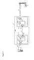
- FIG. 1is a block diagram schematically illustrating principle elements of an exemplary on-frequency repeater in which the present invention may be deployed;
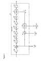
- FIG. 2is a block diagram schematically illustrating principle elements of an exemplary system it accordance with an embodiment of the present invention
- FIG. 3is a block diagram schematically illustrating principle elements of an exemplary uplink AGC usable in the system of FIG. 2 ;
- FIG. 4is a block diagram schematically illustrating principle elements of an exemplary downlink AGC usable in the system of FIG. 2 ;
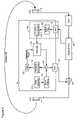
- FIG. 5is a block diagram schematically illustrating exemplary operations of the system of FIG. 2 ;
- FIGS. 6 a and 6 bare respective block diagrams schematically illustrating exemplary operations of the control signal generator of FIG. 5 .
- a first aspect of the present inventionprovides a system for adaptively controlling a coverage area of an on-frequency repeater, such as, for example, an Adaptive Personal Repeater (APR) described in applicant's co-pending U.S. patent application Ser. No. 09/809,218.
- an on-frequency repeateroperates to mediate RF signal traffic between transceivers of the wireless communications network.
- FIG. 1is a block diagram schematically illustrating principle elements of an exemplary repeater in which the system of the present invention may be deployed.
- the repeater 2is functionally positioned between a base station 4 of the wireless communications network (not shown) and the subscriber's Wireless Communications Device (WCD) 6 .
- the repeater 2is an “on-frequency” repeater, in that uplink and downlink RF signals are conveyed through the repeater 2 without altering the respective channel frequencies.
- the repeater 2selectively receives and controls (i.e., amplifies or attenuates) RF signals, without performing any signal formatting or protocol conversion, thereby rendering the repeater 2 transparent to both the base station 4 and the WCD 6 .
- the subscriber's WCD 6may take the form of any conventional wireless communications device, such as, for example, Personal Digital Assistants (PDA's), wireless telephone handsets, pagers, and one and two-way wireless messaging devices.
- PDA'sPersonal Digital Assistants
- the subscribermay possess multiple WCDs 6 , and may use any one or more WCDs 6 simultaneously.
- multiple subscribersmay be located within the wireless space of a single repeater 2 .
- the illustrated embodimentincludes a single WCD 6 within the wireless space defined by the repeater 2 .
- the repeater 2comprises a Directional Donor Unit (DDU) 8 and a Subscriber Coverage Unit (SCU) 10 .
- the DDU 8 and SCU 10may be suitably coupled to each other, for example via a coaxial cable 12 , as shown in FIG. 1 .
- the Directional Donor Unit (DDU) 8operates to establish and maintain a network link 14 between the repeater 2 and the base station 4 .
- the DDU 8is designed to receive downlink signals from the base station 4 at power levels as low as ⁇ 120 dBm, and transmit uplink signals to the base station 4 at an ERP of up to +37 dBm.
- This transmit and receive performance of the DDU 8enables maintenance of the network link 14 with the base station 4 , even when the DDU 8 is located well beyond the conventional cell and/or network coverage area boundary.
- the DDU 8is provided are single port active antenna comprising a Directional Donor Antenna (DDA) 16 integrated with a Transceiver Diplexer (TRD) 18 .
- a bi-directional port 20couples the DDU 8 to the SCU 10 via the coaxial cable 12 .
- the Subscriber Coverage Unit (SCU) 10operates to maintain a local wireless link 22 between the repeater 2 and the subscriber's WCD 6 , and define the coverage area of the repeater 2 . It is anticipated that the coverage area will be very much smaller than a conventional cell of the wireless communications network. For example, in some embodiments, it is expected that the coverage area will extend 25 m (or less) from the SDU 10 . Other embodiments may provide a larger or smaller coverage area, as desired.
- the Subscriber Coverage Unit (SCU) 10is provided as a single port active antenna comprising a Subscriber Coverage Antenna (SCA) 24 integrated with a dual-directional processor (DDP) 26 .
- SCASubscriber Coverage Antenna
- DDPdual-directional processor
- a bi-directional port 28couples the SCU 10 to the DDU 8 via the coaxial cable 12 .
- the DDP 26comprises an Intelligent Gain Controller (IGC) 30 connected between an SCA diplexer 32 and a port diplexer 34 .
- IGCIntelligent Gain Controller
- the SCA diplexer 32is coupled to the SCA 24
- the port diplexer 34is coupled to the bi-directional port 28 .
- These diplexers 32 and 34operate to separate uplink and downlink signal paths 36 and 38 at the SCA 24 and port 28 , respectively.
- the diplexers 32 and 34also operate to define and limit the frequency band(s) over which the IGC 30 must maintain stability.
- the IGC 30is provided as a hybrid RF, analog and digital processing module capable of detecting and selectively controlling (i.e., amplifying and/or attenuating) RF signal traffic between the base station 4 and the WCD 6 .
- the use of a hybrid processing module in this mannerenables the IGC 30 to utilize mathematical (i.e., analog) signal conditioning and gain control techniques, in combination with knowledge-based (i.e., software) control of signal detection and system behaviour.
- the IGC 30includes a wide-band uplink signal path 36 and a wide-band downlink signal path 38 coupled between the diplexers 32 and 34 , and an IF down-converter and narrow-band detector 40 , all of which are controlled by a micro-controller 42 in accordance with an Adaptive Control Algorithm (ACA).
- ACAAdaptive Control Algorithm
- the band-width of the wide-band signal paths 36 , 38will be determined by the communications network, typically in accordance with published standards.
- the communications networktypically in accordance with published standards.
- publicly accessible cellular communications networksutilize a 25 MHz uplink and downlink channel bandwidth centered on 836.5 MHz and 881.5 MHz, respectively.
- the uplink and downlink signal paths 36 and 38can be suitably designed to process RF signals over the entire corresponding 25 MHz band-widths.
- different band-widths, and different center frequenciescan be utilized, as desired.
- the IGC 30 of the present inventionoperates to control (amplify and/or attenuate) uplink channel RF signals received from the WCD 6 for transmission to the base station 4 with a repeater uplink Effective Radiation Power (ERP) that is adjusted (by operation of the IGC 30 ) to a minimum value consistent with satisfactory link performance and prevention of system oscillation.
- ERPEffective Radiation Power
- the IGC 30controls the downlink channel RF signals received from the base station 4 for transmission to the WCD 6 with a repeater downlink ERP that is continuously adjusted (by the IGC 30 ) to a minimum value consistent with satisfactory performance of the local link 22 , and so adaptively control system stability in the downlink path, as will be described in greater detail below. It is anticipated that an repeater downlink ERP of up to about ⁇ 10 dBm will yield satisfactory performance for most installations.
- the uplink path 36comprises a wide-band uplink Automatic Gain Controller (AGC) 44 and a slaved variable gain amplifier (VGA) 46 .
- AGCAutomatic Gain Controller
- VGAslaved variable gain amplifier
- the uplink AGC 44interfaces with the down-converter 40 and the micro-controller 42 , as will be described in greater detail below.
- the uplink path 36is designed to receive, process and transmit RF signals across the entire uplink channel RF operating band. This processing bandwidth is only limited by the network system bandwidth. For example,. North American 800 MHz cellular networks utilize an uplink frequency bandwidth of 25 MHz centered at 836.5 MHz and is divided into carrier A and Carrier B sub-bands.
- the uplink path 36preferably provides substantially constant output leveling over a wide input range.
- the ERP of uplink RF signals transmitted to the base station 4will be substantially independent of variations in the signal power of uplink RF signals received from the WCD 6 .
- the uplink AGC 44is provided as an extremely fast, wide dynamic range, highly linear block including a single VGA stage 46 , fixed gain amplifiers 48 a and 48 b cascaded with band-pass filters 50 , and a directional coupler 52 .
- Inter-stage attenuators 54 a – 54 cmay also be included to optimize performance.
- the gain of the uplink AGC 44has an inverse relationship to the received power of uplink RF signals. Accordingly, the uplink AGC 44 gain is automatically increased as the received uplink RF signal power decreases and the total uplink gain can be controlled by the micro-controller 42 .
- the directional coupler 52which may be a 17 db directional coupler, samples the uplink RF signal downstream of the VGA 46 .
- the sample signalis supplied to a feedback path 56 comprising an RF Variable Log Amplifier (VLA) 58 and a feedback directional coupler 60 which samples the RF signal within the feedback path 56 and supplies the sample signal to the down-converter 40 .
- VLAVariable Log Amplifier
- the RF VLA 58is a variable detection amplifier controlled by the micro-controller 42 .
- the output of the RF VLA 53supplies a gain control signal to the uplink AGC VGA 46 and the downlink slaved VGA 68 (thereby controlling downlink path ERP), and may also be supplied to the micro-controller 42 for decision making in accordance with the Adaptive Control Algorithm (ACA).
- ACAAdaptive Control Algorithm
- the feedback path 56provides a 25 MHz bandwidth path which operates to ensure system stability by providing substantially instantaneous RF AGC feedback.
- the feedback path 56closes the uplink AGC loop, which in turn limits system oscillation by automatically adjusting gain of the VGA 46 in the event of inadequate isolation between the DDA 16 and the SCA 24 .
- the feedback path 56also provides a means by which the gain of the uplink AGC 44 and the downlink slaved VGA 68 can be forced to a low level by the micro-controller 42 to maintain stability during system setup, thereby ensuring the detection of weak desired signals in the downlink path 38 without the need for initial system isolation maximization, and/or to disable the system if a major fault is detected.
- the uplink slaved VGA 46preferably has approximately 60 dB of gain variation, and accepts a gain control input from the micro-controller 42 to provide a hardware means to modulate the power level of the uplink channel output power.
- the uplink path 36may also include an output amplifier stage 62 , along with one or more inter-stage filters 64 a , 64 b .
- the uplink output amplifier 62provides a fixed gain to compensate for losses in the coaxial cable 12 , while the inter-stage filters 64 a , 64 b limit cascaded noise.
- the downlink path 38comprises a wide-band downlink automatic gain controller (AGC) 66 , and a slaved variable gain amplifier (VGA) 68 .
- the downlink AGC 66interfaces with the down-converter 40 and the micro-controller 42 , as will be described in greater detail below.
- the downlink path 38is designed to receive, process and transmit the entire downlink RF channel operating band, for example, North American 800 MHz cellular network has a downlink frequency bandwidth of 25 MHz centered at 881.5 MHz and is divided into carrier A and Carrier B sub-bands.
- the downlink AGC 66preferably provides substantially constant output leveling over a wide input range. As shown in FIG. 4 , the downlink AGC 66 is preferably provided as an extremely fast, wide dynamic range, highly linear block comprising a single VGA stage 70 , a fixed gain amplifier 72 cascaded with a pair of band-pass filters 74 a and 74 b , and a directional coupler 76 . Inter-stage attenuators 78 a – 78 c may also be included to optimize performance.
- the downlink AGC VGA 70preferably has approximately 60 dB of gain variation, and is cascaded with the fixed gain amplifier 72 to enhance system linearity while minimizing the cascaded noise figure.
- the BPFs 74 a and 74 boperate to limit VGA noise to the 25 MHz downlink bandwidth, thereby preventing out-of-band signals from capturing the downlink AGC 66 and saturating the downlink path output amplifier 90 .
- the directional coupler 76which may be a 17 dB directional coupler, samples the downlink RF signal downstream of the VGA 70 .
- the sample signalis supplied is a feedback path 80 which includes a cascaded RF amplifier 82 and RF Variable Log Amplifier (VLA) 84 , and a feedback directional coupler 86 which samples the RF signal within the feedback path 80 and supplies the sample signal to the down-converter 40 .
- the RF VLA 84is preferably a variable detection log amplifier controlled by the micro-controller 42 .
- the output of the RF log amplifier 84supplies a gain control signal to the downlink AGC VGA 70 and the uplink path slaved VGA 46 , and may also be supplied to the micro-controller 42 for decision making in accordance with the ACA.
- the feedback path 80preferably provides a 25 MHz bandwidth path which operates to ensure system stability by providing substantially instantaneous RF AGC feedback.
- the feedback path 80closes the AGC loop, which in turn limits system oscillation by automatically adjusting gain of the VGA 70 in the event of inadequate isolation between the DDA 16 and SCA 24 .
- the feedback path 80also provides a means by which the gain of the downlink AGC 66 can be forced to a low level by the micro-controller 42 to disable the system following detection of a major fault.
- the downlink slaved VGA 68preferably has about 60 dB of gain variation, and accepts a gain control input from the micro-controller 42 to provide a hardware means to modulate the power level of the downlink output power.
- the TGC downlink path 38may also include a pre-amplifier 88 , and an output amplifier stage 90 . These elements can be cascaded with a band-pass filter (BPF) 92 and inter-stage attenuators 94 a and 94 b to reduce cascaded noise and optimize performance.
- the pre-amplifier 88operates to preserve the S/N ratio established by the DDU 8 , and buffers the port diplexer 34 from BPF 92 .
- This BPF 92together with the port diplexer 34 , limits the downlink bandwidth to 25 MHz, rejecting both image and frequency crossover noise and any out-of-band signals, including RF signals in the uplink path 36 .
- the output amplifier 90provides a fixed gain to provide the necessary power output to the SCA 24 .
- the micro controller 42comprises a micro-processor (not shown) operating under the control of suitable software that implements an Adaptive Control Algorithm (ACA), one or more Digital-to-Analog converters (DACs) 108 and Analog-to-Digital Converters (ADCs) 110 which operate, in a manner well known in the art, to provide translation between digital and analog signal formats, and thereby enable interaction between the micro controller 42 and other elements of the IGC 30 .
- ACAAdaptive Control Algorithm
- DACsDigital-to-Analog converters
- ADCsAnalog-to-Digital Converters
- the adaptive control algorithmprovides the necessary processing control for IGC operation without intervention after installation. It may also control operation during system set-up, in order to simplify installation of the repeater 2 .
- the ACAprovides knowledge-based control of the functionality of the IGC 30 , thereby providing dramatically greater versatility than is possible with conventional. (analog math-based) RF signal processing techniques.
- the ACAimplements technique to distinguish leakage signals within each path 36 , 38 , and adaptively adjust the gain to maintain a predetermined level of stability. This functionality is described in greater detail below.
- the method of the inventioninvolves transmitting a unique signature signal, and monitoring received signals to detect a signal component consistent with the transmitted signature. Correlation between the transmitted signature signal and the detected signal component provides an indication of total signal leakage, and thus the system isolation. Based on this information, the micro-controller 42 can control the gain in each of the paths 36 and 38 to limit the signal leakage to a predetermined acceptable level, and thereby ensure unconditional system stability.
- the signature signalmay be provided as any signal pattern that can be reliably detected within the uplink and downlink RF signal traffic. This can conveniently be accomplished by generating a code signal as a predetermined sequence of bits.
- the number of bits in the sequencecan be selected to provide desired properties of speed and reliability. For example, a smaller number of bits can be transmitted, received, and analyzed more rapidly than a longer bit sequence, but at a cost of reduced reliability (due to an increased probability of incorrectly identifying the signature in received RF signals).
- a larger number of bitsenables correspondingly larger number of unique codes to be defined.
- each repeater 2is provided with a unique code. This is valuable in situations in which multiple repeaters 2 may be operating with overlapping coverage areas.
- faulty operationdue, for example, to erroneous identification of a signature signal transmitted by another repeater
- Additional reliabilitycan be obtained by selecting each unique code from among a set of orthogonal codes. The use of orthogonal codes increases the probability that the repeater 2 will be able to distinguish its own signature signal from that of another near-by repeater.
- each bit sequenceis spectrally white.
- This propertywhich can be obtained by using a pseudo-random bit sequence, minimizes harmonics and periodic conditions and effects of the signature signal. This, in turn, causes the signature signal to emulate background noise, and thereby mitigates any disturbance in the performance of either the base station 4 or the WCD 6 . Also, this property allows the signature detection to be immune to any changes in the propagation paths, 14 and 22 resulting from signal fading or changing multipaths.
- FIGS. 5 and 6 a, billustrate exemplary operations of the downlink path 38 , downconverter 40 , and micro-controller 42 for implementing the method of the invention. It will be appreciated that the same operations can equally be implemented in respect of the uplink path 36 . However, it will also be appreciated that the method of invention can apply to either the downlink path or the uplink path and slaving the other path gain via the micro-controller.
- the micro-controller 42operates under control of the ACA to implement a code generator 112 that generates a code signal as a predetermined sequence of bits.
- This code signalcan be repeated continuously, or at predetermined intervals, as desired.
- the code signalis shaped (at 114 ) (e.g. by modulating the code signal with a predetermined fade) to produce the signature signal, which is then used as control signal for controlling the downlink slaved VGA 68 to modulate the downlink path gain, and thereby insert the signature signal as a low-level amplitude dither of the downlink RF signals transmitted by the SCA 24 .
- the modulation powercan be kept low enough (e.g.
- the signature signalis also sampled (at 116 ), digitized by a threshold comparator 118 , and subjected to a predetermined delay (at 120 ) to generate a reference signal.
- the length of the delay 120is preferably selected based on the propagation delay of signals through the leakage path. In some cases, this value may be known in advance, in which case a fixed delay can be used. However, in most cases and depending on the modulation rate, it will not be necessary to detect the propagation delay, since the propagation delay is negligible compared to the correction time.
- One known method of detecting the propagation delayis to measure the time interval (e.g. using a suitable clock) between generation of the signature signal and detection of signal components in the received RF signals corresponding to the signature. This measured time interval can then be used to determine the delay 120 , such that corresponding bits of the signature signal and detected signal components can be processed simultaneously to facilitate correlation of the signature and detected signal components.
- the signature detector 102comprises the AGC detector 84 , the samples 110 , the digital filter 124 and the threshold comparator 126 .
- the detector 84 of the downlink AGC 66analyses downlink RF signals received through the DDA 16 to detect all signal components including noise corresponding to the signature signal. For this purpose, the signature detector 102 samples (at 110 ) the downlink RF signals over the entire RF band, digitally filters the sample signal (at 124 ), and then compares the sample signal to a predetermined a threshold (at 126 ) to generate a digitized signal component.
- the signal component generated by the signature detector 102is then correlated in time (at 119 ) with the reference signal, to obtain an indication of the signal leakage between the SCA 24 and the DDA 16 .
- the micro-controller 42can then adjust (i.e. increase or decrease, as appropriate) the gain of the downlink VGA 68 to optimize the downlink: path gain. Because the leakage path has the same loss from the SCA 24 to DDA 16 for the downlink and from the DDA 16 to the SCA 24 for the uplink, the micro-controller 42 can also adjust the gain of the uplink VGA 46 accordingly to optimize the uplink path gain.
- FIGS. 6 a and 6 billustrate principle steps in respective alternative methods of correlating the signal component and the reference signal, and generating a gain control signal to adjust the downlink VGA gain which can be implemented by either software or hardware.
- a first method of correlating the signal component and the reference signalinvolves supplying successive bits, of the detected signal component and the reference signal to respective inputs of an Exclusive OR (Ex-OR) logic gate function 128 .
- the result of the Ex-OR operationcan then be averaged (at 130 ) to yield a correlation signal, the level of which is indicative of the similarity between the reference signal and the signal component supplied by the detector 102 .
- a high degree of similaritywhich is indicative of a large amount of signal leakage, yields a corresponding high level of the correlation signal.
- a low degree of similaritywhich is indicative of a low amount of signal leakage, yields a corresponding low level of the correlation signal.
- a decision state reflecting whether the amount of signal leakage is above an acceptable limitcan be set by comparing the correlation signal to predetermined threshold (at 132 ).
- an alternative method of correlating the signal component and the reference signalinvolves calculating a correlation function 139 known in the art.
- the result of the correlation functionprovides direct indication of the similarity between the reference signal and the signal component supplied by the detector 102 .
- a high degree of similaritywhich is indicative of a large amount of signal leakage, yields a corresponding high result of the correlation function.
- a low degree of similaritywhich is indicative of a low amount of :signal leakage, yields a corresponding low result of the correlation function.
- a decision state reflecting whether the amount of signal leakage is above an acceptable limitcan be set by comparing the correlation result to a predetermined threshold 136 .
- the threshold comparison resultcan be integrated at 138 (over time) to eliminate short-period transient effects, and a VGA gain control signal 68 generated using the absolute value of the integration result.
- the predetermined threshold level of acceptable signal leakagecan be suitably selected to provide a balance between system stability (i.e., resistance to oscillation) and performance of the network and local wireless links 14 and 22 .
- system stabilityi.e., resistance to oscillation
- performance of the network and local wireless links 14 and 22e.g., performance of the network and local wireless links 14 and 22 .
- other sources of isolation between the SCA 24 and the DDA 16e.g., front to back ratios of the DDA 16 and SCA 24 ; polarization loss and propagation losses
- it is possible to set a threshold levelwhich ensures unconditional system stability while preserving sufficient range of gain variation in the uplink and downlink paths 36 and 38 to deliver satisfactory performance of the network and local wireless links 14 and 22 .
- Prior art repeaterstypically require 10–15 db of isolation/gain margin, Because the method of the present invention is continuously adaptive, 6 dB of isolation/gain margin is possible to maintain an unconditional stable system, with wide variations in gain and isolation changes. This gain improvement of 4 to 9 dB effectively doubles the coverage area, or for a given coverage area allows the repeater to be installed at a distance approximately two times further from the base station than would be possible with prior art systems.
- the unique signature signalcan also be used to actively mitigate the effect of spatial nulls within overlapping coverage areas.
- each repeatertransmits a unique signature signal which is preferably inserted into transmitted signal traffic (in either of the uplink or downlink paths 36 or 38 ) as a form of modulation or dither (either in amplitude and/or phase) effecting the entire bandwidth of the relevant channel.
- Generation of the signature signal using a unique pseudo-random bit sequenceensures that each repeater will transmit a unique signature signal. Because the location of spatial nulls is dependent on the phase and amplitude of signals received from, multiple transmitters, any changes in either of these parameters will result in an associated change in the location of a spatial null.
- a continuous, or periodic, change in either of these parameters, in accordance with the present invention,will therefore produce corresponding movement of spatial nulls within areas overlapping coverage.
- the distance and speed of movementwill normally be a function of the peak-to-peak modulation power, and the first time derivative of modulation power (which, in turn, is a function of the bit rate of the code used to generate the signature signal).
- a low level signal modulatione.g. of 2–5 dB
- This level of modulation powerin combination with a moderate bit rate (of, for example, a few kilo-Hertz) can yield a speed of movement on the order of hundreds of meters per second.
- This degree of spatial null movementdramatically reduces the probability that a subscriber's wireless communications device will be located within a spatial null long enough to interrupt communications.
- this aspect of the present inventionis not limited to areas served by multiple APRs 2 , or any specific type of repeater. Rather, the method of the invention can be used to mitigate effects of spatial nulls in any wireless environment in which spatial nulls can form. Thus the present invention may be used to improve communications reliability in any wireless network in which two or more transmitters radiate signals (at the same frequency) into overlapping areas of coverage.
- the present inventionprovides a system capable of adaptively controlling the stability of an on-frequency repeater, and actively controls spatial nulls to prevent loss of communications within overlapping areas of coverage.
- a unique signature signalis imposed on RF signals transmitted by the repeater, and RF signals received by the repeater analyzed to detect signal components corresponding to the signature The signature and the detected signal component are correlated by the micro-controller, which operates under control of an Adaptive Control Algorithm to adjust the ERP of RF signals transmitted by the repeater to limit signal leakage and thereby control the stability of the repeater.
- the unique signature signalcauses predetermined, pseudo-random movement of spatial nulls, thereby reducing the probability of a subscriber's wireless communications device suffering loss of signal due to encountering a fixed spatial null.
Landscapes
- Engineering & Computer Science (AREA)
- Computer Networks & Wireless Communication (AREA)
- Signal Processing (AREA)
- Mobile Radio Communication Systems (AREA)
- Radio Relay Systems (AREA)
Abstract
Description
Claims (46)
Priority Applications (4)
| Application Number | Priority Date | Filing Date | Title |
|---|---|---|---|
| PCT/CA2002/001211WO2003013005A2 (en) | 2001-08-02 | 2002-08-02 | Adaptive on-frequency repeater |
| AU2002313423AAU2002313423A1 (en) | 2001-08-02 | 2002-08-02 | Adaptive on-frequency repeater |
| DE60218479TDE60218479T2 (en) | 2001-08-02 | 2002-08-02 | COVER AREA SIGNATURE IN AN ADAPTIVE ON-FREQUENCY INTERMEDIATE AMPLIFIER |
| EP02752917AEP1413063B1 (en) | 2001-08-02 | 2002-08-02 | Coverage area signature in an on-frequency repeater |
Applications Claiming Priority (3)
| Application Number | Priority Date | Filing Date | Title |
|---|---|---|---|
| CA2,323,881 | 2000-10-18 | ||
| CA002323881ACA2323881A1 (en) | 2000-10-18 | 2000-10-18 | Adaptive personal repeater |
| US09/809,218US20040097189A1 (en) | 2000-10-18 | 2001-03-16 | Adaptive personal repeater |
Related Parent Applications (1)
| Application Number | Title | Priority Date | Filing Date |
|---|---|---|---|
| US09/809,218Continuation-In-PartUS20040097189A1 (en) | 2000-10-18 | 2001-03-16 | Adaptive personal repeater |
Publications (2)
| Publication Number | Publication Date |
|---|---|
| US20020044594A1 US20020044594A1 (en) | 2002-04-18 |
| US7088953B2true US7088953B2 (en) | 2006-08-08 |
Family
ID=25682171
Family Applications (1)
| Application Number | Title | Priority Date | Filing Date |
|---|---|---|---|
| US09/919,888Expired - Fee RelatedUS7088953B2 (en) | 2000-10-18 | 2001-08-02 | Coverage area signature in an on-frequency repeater |
Country Status (5)
| Country | Link |
|---|---|
| US (1) | US7088953B2 (en) |
| EP (1) | EP1327369A1 (en) |
| CN (1) | CN1470144A (en) |
| AU (1) | AU2002210299A1 (en) |
| WO (1) | WO2002033996A1 (en) |
Cited By (10)
| Publication number | Priority date | Publication date | Assignee | Title |
|---|---|---|---|---|
| US20040009768A1 (en)* | 2002-04-30 | 2004-01-15 | Waters John Deryk | Wireless data network security |
| US20050272367A1 (en)* | 2004-05-26 | 2005-12-08 | Rodgers Michael W | Wireless repeater implementing low-level oscillation detection and protection for a duplex communication system |
| US20080225775A1 (en)* | 2007-03-02 | 2008-09-18 | Qualcomm Incorporated | Physical Layer Repeater Utilizing Real Time Measurement Metrics and Adaptive Antenna Array to Promote Signal Integrity and Amplification |
| US20090154390A1 (en)* | 2003-07-31 | 2009-06-18 | Microsoft Corporation | Local area network translating bi-directional packet repeater |
| US20100075595A1 (en)* | 2008-04-17 | 2010-03-25 | Cellynx, Inc. | Dual Loop Active and Passive Repeater Antenna Isolation Improvement |
| US20110143658A1 (en)* | 2009-12-11 | 2011-06-16 | Van Hanson | System and method for determining and controlling gain margin in an rf repeater |
| US20130072112A1 (en)* | 2011-09-21 | 2013-03-21 | Fredrik Gunnarsson | System and method for operating a repeater |
| US8744340B2 (en) | 2010-09-13 | 2014-06-03 | Qualcomm Incorporated | Method and apparatus of obtaining timing in a repeater |
| US8787429B2 (en) | 2012-06-19 | 2014-07-22 | Andrew Llc | Communication system with channel compensating equalizer |
| US9203503B2 (en) | 2001-11-12 | 2015-12-01 | Andrew Wireless Systems Gmbh | Digital repeater having bandpass filtering, adaptive pre-equalization and suppression of natural oscillation |
Families Citing this family (99)
| Publication number | Priority date | Publication date | Assignee | Title |
|---|---|---|---|---|
| US7088953B2 (en) | 2000-10-18 | 2006-08-08 | Spotwave Wireless Canada Inc. | Coverage area signature in an on-frequency repeater |
| US7574230B1 (en) | 2001-05-31 | 2009-08-11 | Sprint Spectrum L.P. | Remote base station with transmit power control |
| WO2003013028A1 (en)* | 2001-08-02 | 2003-02-13 | Spotwave Wireless Inc. | Adaptive coverage area control in an on-frequency repeater |
| WO2003013005A2 (en)* | 2001-08-02 | 2003-02-13 | Spotwave Wireless Inc. | Adaptive on-frequency repeater |
| IL161882A0 (en) | 2001-11-20 | 2005-11-20 | Qualcomm Inc | Reverse link power controlled repeater qualcomm incorporated |
| US7831263B2 (en) | 2002-11-08 | 2010-11-09 | Qualcomm Incorporated | Apparatus and method for determining the location of a repeater |
| US7035321B2 (en)* | 2002-11-20 | 2006-04-25 | Spotwave Wireless Canada, Inc. | Monitoring stability of an on-frequency repeater |
| GB2411797B (en)* | 2002-12-16 | 2006-03-01 | Widefi Inc | Improved wireless network repeater |
| US6961367B2 (en)* | 2003-02-24 | 2005-11-01 | Qualcomm, Incorporated | Forward link repeater frequency watermarking scheme |
| US6993287B2 (en) | 2003-03-04 | 2006-01-31 | Four Bars Clarity, Llc | Repeater system for strong signal environments |
| US7555261B2 (en) | 2003-03-04 | 2009-06-30 | O'neill Frank P | Repeater system for strong signal environments |
| CA2421341A1 (en)* | 2003-03-07 | 2004-09-07 | Spotwave Wireless Inc. | Distributed adaptive repeater system |
| US20050176368A1 (en)* | 2003-03-07 | 2005-08-11 | Spotwave Wireless Inc. | Distributed adaptive repeater system |
| CN100531167C (en)* | 2003-05-28 | 2009-08-19 | 艾利森电话股份有限公司 | Method and system for wireless communication networks using relaying |
| AU2004303118A1 (en)* | 2003-09-03 | 2005-03-17 | Behzad Mohebbi | Short-range cellular booster |
| KR20050027961A (en)* | 2003-09-16 | 2005-03-21 | 주식회사 블루맥스 커뮤니케이션 | A personal repeater using rf coupling |
| WO2005055478A1 (en)* | 2003-12-05 | 2005-06-16 | Spotwave Wireless Inc. | Distributed repeater architecture |
| US7480485B1 (en) | 2004-01-07 | 2009-01-20 | Sprint Spectrum L.P. | Radio frequency repeater with automated block/channel selection |
| US7299005B1 (en) | 2004-01-07 | 2007-11-20 | Sprint Spectrum L.P. | Radio frequency repeater with automated block/channel selection |
| ES2551028T3 (en)* | 2004-01-12 | 2015-11-13 | Nextivity, Inc. | Short range cell amplifier |
| US7639806B2 (en)* | 2004-03-24 | 2009-12-29 | Iowa State University Research Foundation, Inc. | Fingerprinting digital devices using electromagnetic characteristics of their communications |
| MXPA06011461A (en) | 2004-04-05 | 2006-12-20 | Qualcomm Inc | Repeater with positioning capabilities. |
| JP2007532079A (en) | 2004-04-05 | 2007-11-08 | クゥアルコム・インコーポレイテッド | A repeater that reports detected neighbors |
| US8045917B2 (en)* | 2004-05-12 | 2011-10-25 | Andrew, Llc | System and method for detection of mobile operating through a repeater |
| US7778596B2 (en) | 2004-07-29 | 2010-08-17 | Qualcomm Incorporated | Airlink sensing watermarking repeater |
| US20060034351A1 (en)* | 2004-08-13 | 2006-02-16 | Spotwave Wireless Inc. | Monitoring stability of an on-frequency repeater |
| US20060205343A1 (en)* | 2005-03-11 | 2006-09-14 | Runyon Donald L | Wireless repeater with feedback suppression features |
| US7848758B1 (en) | 2005-09-27 | 2010-12-07 | Sprint Spectrum L.P. | Dynamic allocation of carrier frequencies in wireless wide area networks |
| CN100370711C (en)* | 2006-01-24 | 2008-02-20 | 京信通信技术(广州)有限公司 | TD-SCDMA repeater system for third generation mobile communication system |
| WO2007087649A1 (en)* | 2006-01-27 | 2007-08-02 | Qualcomm Incorporated | Repeater open loop gain measurement |
| US20070232228A1 (en)* | 2006-04-04 | 2007-10-04 | Mckay David L Sr | Wireless repeater with universal server base unit and modular donor antenna options |
| US7623866B1 (en) | 2006-07-10 | 2009-11-24 | Sprint Spectrum L.P. | Automatic generation of neighbor lists in a wireless network |
| KR100890634B1 (en)* | 2006-12-06 | 2009-03-27 | 한국전자통신연구원 | Rf repeater of time division duplexing and method thereof |
| US8295763B2 (en) | 2008-06-23 | 2012-10-23 | Andrew Llc | System and method for identifying the path or devices on the path of a communication signal using (1+r(T)) amplitude modulation |
| US8498241B1 (en) | 2009-03-10 | 2013-07-30 | Sprint Spectrum L.P. | Use of macro-network channel-list messages for selection of carriers for low-cost internet base-station frequency-hopping pilot beacons |
| US8086174B2 (en) | 2009-04-10 | 2011-12-27 | Nextivity, Inc. | Short-range cellular booster |
| US8325648B1 (en) | 2009-04-29 | 2012-12-04 | Sprint Spectrum L.P. | Methods and systems for assigning a wireless communication device to a carrier frequency |
| US8320313B1 (en) | 2009-06-19 | 2012-11-27 | Sprint Spectrum L.P. | Method and system for carrier frequency management based on slot contention |
| US9107148B1 (en) | 2009-11-30 | 2015-08-11 | Sprint Spectrum L.P. | Use of pre-handoff macro-carrier data for prioritization of carriers in femtocell frequency-hopping pilot beacons |
| US8798013B1 (en) | 2011-03-25 | 2014-08-05 | Sprint Spectrum L.P. | Method and system for management of data transmission in timeslots |
| US8787824B2 (en)* | 2011-09-21 | 2014-07-22 | Telefonaktiebolaget L M Ericsson (Publ) | System and method for determining repeater gain |
| CN105206898B (en)* | 2012-07-04 | 2018-11-30 | 华为技术有限公司 | Microwave telecommunication devices and microwave telecommunication system |
| US20170055214A1 (en) | 2015-08-18 | 2017-02-23 | Wilson Electronics, Llc | Wireless device signal amplifier |
| US10862529B2 (en) | 2015-08-18 | 2020-12-08 | Wilson Electronics, Llc | Separate uplink and downlink antenna repeater architecture |
| WO2017066691A1 (en) | 2015-10-14 | 2017-04-20 | Wilson Electronics, Llc | Channelization for signal boosters |
| US10715302B2 (en) | 2015-10-14 | 2020-07-14 | Wilson Electronics, Llc | Channelization for signal boosters |
| US10424822B2 (en) | 2015-10-14 | 2019-09-24 | Wilson Electronics, Llc | Multi-common port multiband filters |
| EP3378170B1 (en) | 2015-11-17 | 2023-08-23 | Wilson Electronics, LLC | Cellular signal booster with multiple signal chains |
| CN109328440A (en) | 2016-04-05 | 2019-02-12 | 威尔逊电子有限责任公司 | Narrow band signal for network protection detects |
| CN109792289A (en) | 2016-09-23 | 2019-05-21 | 威尔逊电子有限责任公司 | To the location-based access of selected communications band |
| CA3037957A1 (en) | 2016-09-23 | 2018-03-29 | Wilson Electronics, Llc | Booster with an integrated satellite location system module |
| CN109792291A (en) | 2016-10-07 | 2019-05-21 | 威尔逊电子有限责任公司 | Narrow band signal detection |
| WO2018067866A1 (en) | 2016-10-07 | 2018-04-12 | Wilson Electronics, Llc | Multi-amplifier repeaters for a wireless communication system |
| US11031994B2 (en) | 2016-11-15 | 2021-06-08 | Wilson Electronics, Llc | Signal booster for boosting signals in contiguous bands |
| US10673517B2 (en) | 2016-11-15 | 2020-06-02 | Wilson Electronics, Llc | Desktop signal booster |
| EP4246768A3 (en) | 2016-11-15 | 2023-11-01 | Wilson Electronics, LLC | Desktop signal booster |
| EP3577797B1 (en) | 2017-01-31 | 2023-08-16 | Wilson Electronics, LLC | Reducing oscillation in a signal booster |
| US10432294B2 (en) | 2017-02-02 | 2019-10-01 | Wilson Electronics, Llc | Signal booster with spectrally adjacent bands |
| US10873387B2 (en) | 2017-02-02 | 2020-12-22 | Wilson Electronics, Llc | Signal booster with spectrally adjacent bands |
| WO2018144939A1 (en) | 2017-02-02 | 2018-08-09 | Wilson Electronics, Llc | Independent band detection for network protection |
| US20180227039A1 (en) | 2017-02-09 | 2018-08-09 | Wilson Electronics, Llc | Amplification adjustment techniques for a wireless repeater |
| EP3607671A1 (en) | 2017-04-06 | 2020-02-12 | Wilson Electronics, LLC | Techniques for configuring the power or gain of a repeater |
| CA3058659A1 (en) | 2017-04-07 | 2018-10-11 | Wilson Electronics, Llc | Multi-amplifier repeater system for wireless communication |
| CN110537338A (en) | 2017-04-11 | 2019-12-03 | 威尔逊电子有限责任公司 | Signal Booster with coaxial cable connection |
| US10523305B2 (en) | 2017-05-11 | 2019-12-31 | Wilson Electronics, Llc | Variable channelized bandwidth booster |
| EP3639406A1 (en) | 2017-06-16 | 2020-04-22 | Wilson Electronics, LLC | A pole integrated repeater system |
| US20190196555A1 (en)* | 2017-06-16 | 2019-06-27 | Wilson Electronics, Llc | Multiple donor antenna repeater |
| US10673518B2 (en) | 2017-06-27 | 2020-06-02 | Wilson Electronics, Llc | Crossover isolation reduction in a signal booster |
| EP3451532A1 (en) | 2017-08-31 | 2019-03-06 | Wilson Electronics, LLC | Protection of power amplifiers in a signal booster |
| US10715244B2 (en) | 2017-12-29 | 2020-07-14 | Wilson Electronics, Llc | Signal booster with balanced gain control |
| EP3509229B1 (en) | 2018-01-04 | 2022-03-02 | Wilson Electronics, LLC | Detection of line loss in signal booster system |
| CA3034055A1 (en) | 2018-02-21 | 2019-08-21 | Wilson Electronics, Llc | Wireless device cradles |
| US11411635B2 (en)* | 2018-03-19 | 2022-08-09 | Mediatek Singapore Pte. Ltd. | Spatial reuse in WLAN multi-AP network |
| US10879995B2 (en) | 2018-04-10 | 2020-12-29 | Wilson Electronics, Llc | Feedback cancellation on multiband booster |
| US11627482B2 (en) | 2018-04-19 | 2023-04-11 | Wilson Electronics, Llc | Repeater with integrated modem for remote monitoring |
| US10855363B2 (en) | 2018-05-07 | 2020-12-01 | Wilson Electronics, Llc | Multiple-input multiple-output (MIMO) repeater system |
| US10897070B2 (en) | 2018-08-01 | 2021-01-19 | Wilson Electronics, Llc | Connect RV mount |
| EP3621215A1 (en) | 2018-09-07 | 2020-03-11 | Wilson Electronics, LLC | Channelization options for reducing network sensitivity |
| US11218237B2 (en) | 2018-09-27 | 2022-01-04 | Wilson Electronics, Llc | Intermediate frequency (IF) filtering for enhanced crossover attenuation in a repeater |
| US11303369B2 (en) | 2018-10-09 | 2022-04-12 | Wilson Electronics, Llc | Booster gain adjustment based on user equipment (UE) need |
| US10659142B1 (en) | 2018-12-04 | 2020-05-19 | Wilson Electronics, Llc | Independent band detection for network protection |
| US11038542B2 (en) | 2018-12-31 | 2021-06-15 | Wilson Electronics, Llc | Active multiplexer repeater accessory |
| US11418253B2 (en) | 2018-12-31 | 2022-08-16 | Wilson Electronics, Llc | Time division duplex (TDD) repeater configured to communicate with a spectrum access system (SAS) |
| US11894910B2 (en) | 2018-12-31 | 2024-02-06 | Wilson Electronics, Llc | Cellular and public safety repeater |
| WO2020205653A1 (en) | 2019-04-01 | 2020-10-08 | Wilson Electronics, Llc | Combined duplexer |
| CA3077930A1 (en) | 2019-04-17 | 2020-10-17 | Wilson Electronics, Llc. | Carrier-aggregation repeater |
| EP3734859A1 (en) | 2019-04-29 | 2020-11-04 | Wilson Electronics, LLC | Adjusting repeater gain based on antenna feedback path loss |
| US11031995B2 (en) | 2019-05-15 | 2021-06-08 | Wilson Electronics, Llc | Multi-use booster |
| US11223415B2 (en) | 2019-05-24 | 2022-01-11 | Wilson Electronics, Llc | Repeater with low power mode for mobile operations |
| US12120620B2 (en) | 2019-05-29 | 2024-10-15 | Wilson Electronics, Llc | Multiplex time division duplex (TDD) sync detection module |
| US11233492B2 (en) | 2019-06-05 | 2022-01-25 | Wilson Electronics, Llc | Power amplifier (PA)-filter output power tuning |
| DE102019208987A1 (en)* | 2019-06-19 | 2020-12-24 | Molex Cvs Dabendorf Gmbh | Circuit arrangement for the transmission of radio signals and method for operating a circuit arrangement |
| CA3104157A1 (en) | 2019-12-31 | 2021-06-30 | Wilson Electronics, Llc. | Repeater with carrier-specific information |
| CA3104166A1 (en) | 2019-12-31 | 2021-06-30 | Wilson Electronics, Llc. | Repeater with carrier-specific information |
| US11418251B2 (en) | 2020-05-22 | 2022-08-16 | Wilson Electronics, Llc | Signal booster for spectrally adjacent bands |
| US20210409104A1 (en) | 2020-06-26 | 2021-12-30 | Wilson Electronics, Llc | Time division duplex (tdd) network protection repeater |
| US11362729B2 (en) | 2020-07-01 | 2022-06-14 | Wilson Electronics, Llc | Pre-amplifier for a modem |
| US11705958B2 (en) | 2020-07-10 | 2023-07-18 | Wilson Electronics, Llc | Software-defined filtering in a repeater |
| US12191972B2 (en) | 2020-08-06 | 2025-01-07 | Wilson Electronics, Llc | Multiband repeater architecture |
Citations (10)
| Publication number | Priority date | Publication date | Assignee | Title |
|---|---|---|---|---|
| US4317217A (en) | 1980-08-11 | 1982-02-23 | Motorola, Inc. | Tag generator for a same-frequency repeater |
| EP0302455A2 (en) | 1987-08-03 | 1989-02-08 | Allen Telecom Group, Inc. | Booster |
| US4849963A (en) | 1985-10-15 | 1989-07-18 | Minori Kawano | Cellular radio telephone enhancement circuit |
| EP0724336A2 (en) | 1995-01-27 | 1996-07-31 | Nec Corporation | Mobile satellite communication terminal |
| US5564074A (en) | 1993-02-05 | 1996-10-08 | Nokia Mobile Phones Ltd. | Power control apparatus and method for a radiotelephone |
| EP0851606A2 (en) | 1996-12-30 | 1998-07-01 | Lucent Technologies Inc. | Range repeater for a transmission system |
| US5812951A (en) | 1994-11-23 | 1998-09-22 | Hughes Electronics Corporation | Wireless personal communication system |
| US5815795A (en) | 1995-08-25 | 1998-09-29 | Sumitomo Electric Industries, Ltd. | Oscillation detecting system for wireless repeater |
| US5937332A (en) | 1997-03-21 | 1999-08-10 | Ericsson, Inc. | Satellite telecommunications repeaters and retransmission methods |
| US20020044594A1 (en) | 2000-10-18 | 2002-04-18 | Spotwave Wireless Inc. | Coverage area signature in an on-frequency repeater |
- 2001
- 2001-08-02USUS09/919,888patent/US7088953B2/ennot_activeExpired - Fee Related
- 2001-10-18AUAU2002210299Apatent/AU2002210299A1/ennot_activeAbandoned
- 2001-10-18CNCNA018176127Apatent/CN1470144A/enactivePending
- 2001-10-18WOPCT/CA2001/001454patent/WO2002033996A1/ennot_activeApplication Discontinuation
- 2001-10-18EPEP01978037Apatent/EP1327369A1/ennot_activeWithdrawn
Patent Citations (11)
| Publication number | Priority date | Publication date | Assignee | Title |
|---|---|---|---|---|
| US4317217A (en) | 1980-08-11 | 1982-02-23 | Motorola, Inc. | Tag generator for a same-frequency repeater |
| US4849963A (en) | 1985-10-15 | 1989-07-18 | Minori Kawano | Cellular radio telephone enhancement circuit |
| EP0302455A2 (en) | 1987-08-03 | 1989-02-08 | Allen Telecom Group, Inc. | Booster |
| US5564074A (en) | 1993-02-05 | 1996-10-08 | Nokia Mobile Phones Ltd. | Power control apparatus and method for a radiotelephone |
| US5812951A (en) | 1994-11-23 | 1998-09-22 | Hughes Electronics Corporation | Wireless personal communication system |
| EP0724336A2 (en) | 1995-01-27 | 1996-07-31 | Nec Corporation | Mobile satellite communication terminal |
| US5815795A (en) | 1995-08-25 | 1998-09-29 | Sumitomo Electric Industries, Ltd. | Oscillation detecting system for wireless repeater |
| EP0851606A2 (en) | 1996-12-30 | 1998-07-01 | Lucent Technologies Inc. | Range repeater for a transmission system |
| US5835848A (en)* | 1996-12-30 | 1998-11-10 | Lucent Technologies Inc. | Range repeater for a transmission system |
| US5937332A (en) | 1997-03-21 | 1999-08-10 | Ericsson, Inc. | Satellite telecommunications repeaters and retransmission methods |
| US20020044594A1 (en) | 2000-10-18 | 2002-04-18 | Spotwave Wireless Inc. | Coverage area signature in an on-frequency repeater |
Cited By (32)
| Publication number | Priority date | Publication date | Assignee | Title |
|---|---|---|---|---|
| US9929793B2 (en) | 2001-11-12 | 2018-03-27 | Andrew Wireless Systems Gmbh | Digital repeater having bandpass filtering, adaptive pre-equalization and suppressin of natural oscillation |
| US9203503B2 (en) | 2001-11-12 | 2015-12-01 | Andrew Wireless Systems Gmbh | Digital repeater having bandpass filtering, adaptive pre-equalization and suppression of natural oscillation |
| US7376384B2 (en)* | 2002-04-30 | 2008-05-20 | Hewlett-Packard Development Company, L.P. | Wireless data network security |
| US20040009768A1 (en)* | 2002-04-30 | 2004-01-15 | Waters John Deryk | Wireless data network security |
| US20090154390A1 (en)* | 2003-07-31 | 2009-06-18 | Microsoft Corporation | Local area network translating bi-directional packet repeater |
| US8085701B2 (en)* | 2003-07-31 | 2011-12-27 | Microsoft Corporation | Local area network translating bi-directional packet repeater |
| US20050272367A1 (en)* | 2004-05-26 | 2005-12-08 | Rodgers Michael W | Wireless repeater implementing low-level oscillation detection and protection for a duplex communication system |
| US7706744B2 (en)* | 2004-05-26 | 2010-04-27 | Wireless Extenders, Inc. | Wireless repeater implementing low-level oscillation detection and protection for a duplex communication system |
| US20080225930A1 (en)* | 2007-03-02 | 2008-09-18 | Qualcomm Incorporated | Use of a Filterbank in an Adaptive On-Channel Repeater Utilizing Adaptive Antenna Arrays |
| US7911985B2 (en) | 2007-03-02 | 2011-03-22 | Qualcomm Incorporated | Automatic gain control and filtering techniques for use in on-channel repeater |
| US20080232241A1 (en)* | 2007-03-02 | 2008-09-25 | Qualcomm Incorporated | Superimposed Composite Channel Filter |
| US8619837B2 (en) | 2007-03-02 | 2013-12-31 | Qualcomm Incorporated | Use of adaptive antenna array in conjunction with an on-channel repeater to improve signal quality |
| US20080225758A1 (en)* | 2007-03-02 | 2008-09-18 | Qualcomm Incorporated | Automatic Gain Control and Filtering Techniques for Use in On-Channel Repeater |
| US7907891B2 (en) | 2007-03-02 | 2011-03-15 | Qualcomm Incorporated | Physical layer repeater utilizing real time measurement metrics and adaptive antenna array to promote signal integrity and amplification |
| US7907513B2 (en) | 2007-03-02 | 2011-03-15 | Qualcomm Incorporated | Superimposed composite channel filter |
| US20080311848A1 (en)* | 2007-03-02 | 2008-12-18 | Qualcomm Incorporated | Configuration of a Repeater |
| US20080225931A1 (en)* | 2007-03-02 | 2008-09-18 | Qualcomm Incorporated | Use of Adaptive Antenna Array in Conjunction with an On-Channel Repeater to Improve Signal Quality |
| US20080225929A1 (en)* | 2007-03-02 | 2008-09-18 | Qualcomm Incorporated | Closed Form Calculation of Temporal Equalizer Weights Used in a Repeater Transmitter Leakage Cancellation System |
| US8116239B2 (en) | 2007-03-02 | 2012-02-14 | Qualcomm Incorporated | Use of a filterbank in an adaptive on-channel repeater utilizing adaptive antenna arrays |
| US8121535B2 (en) | 2007-03-02 | 2012-02-21 | Qualcomm Incorporated | Configuration of a repeater |
| RU2451412C2 (en)* | 2007-03-02 | 2012-05-20 | Квэлкомм Инкорпорейтед | Automatic gain control and filtering techniques for use in channel repeater |
| US20080225775A1 (en)* | 2007-03-02 | 2008-09-18 | Qualcomm Incorporated | Physical Layer Repeater Utilizing Real Time Measurement Metrics and Adaptive Antenna Array to Promote Signal Integrity and Amplification |
| US8599906B2 (en) | 2007-03-02 | 2013-12-03 | Qualcomm Incorporated | Closed form calculation of temporal equalizer weights used in a repeater transmitter leakage cancellation system |
| US20100075595A1 (en)* | 2008-04-17 | 2010-03-25 | Cellynx, Inc. | Dual Loop Active and Passive Repeater Antenna Isolation Improvement |
| US20110143658A1 (en)* | 2009-12-11 | 2011-06-16 | Van Hanson | System and method for determining and controlling gain margin in an rf repeater |
| US8948687B2 (en) | 2009-12-11 | 2015-02-03 | Andrew Llc | System and method for determining and controlling gain margin in an RF repeater |
| USRE47075E1 (en) | 2009-12-11 | 2018-10-02 | Commscope Technologies Llc | System and method for determining and controlling gain margin in an RF repeater |
| US8744340B2 (en) | 2010-09-13 | 2014-06-03 | Qualcomm Incorporated | Method and apparatus of obtaining timing in a repeater |
| US9083434B2 (en)* | 2011-09-21 | 2015-07-14 | Telefonaktiebolaget L M Ericsson (Publ) | System and method for operating a repeater |
| US20130072112A1 (en)* | 2011-09-21 | 2013-03-21 | Fredrik Gunnarsson | System and method for operating a repeater |
| US8787429B2 (en) | 2012-06-19 | 2014-07-22 | Andrew Llc | Communication system with channel compensating equalizer |
| US10148339B2 (en) | 2012-06-19 | 2018-12-04 | Commscope Technologies Llc | Communication system with channel compensating equalizer |
Also Published As
| Publication number | Publication date |
|---|---|
| AU2002210299A1 (en) | 2002-04-29 |
| EP1327369A1 (en) | 2003-07-16 |
| WO2002033996A1 (en) | 2002-04-25 |
| US20020044594A1 (en) | 2002-04-18 |
| CN1470144A (en) | 2004-01-21 |
Similar Documents
| Publication | Publication Date | Title |
|---|---|---|
| US7088953B2 (en) | Coverage area signature in an on-frequency repeater | |
| US6889033B2 (en) | Intelligent gain control in an on-frequency repeater | |
| US7593689B2 (en) | Method for detecting an oscillation in an on-frequency repeater | |
| JP3782616B2 (en) | Booster, monitoring device, booster system, control method and monitoring method | |
| CA2120768C (en) | Transmitter power control system | |
| FI109495B (en) | Regulation of transmission power in a cellular CDMA cellular telephone system | |
| US20050176368A1 (en) | Distributed adaptive repeater system | |
| EP1413063B1 (en) | Coverage area signature in an on-frequency repeater | |
| US5457811A (en) | System for controlling signal level at both ends of a transmission sink based on a detected value | |
| EP0948869B1 (en) | Load monitoring and management in a cdma wireless communication system | |
| US7409186B2 (en) | Detection and elimination of oscillation within cellular network amplifiers | |
| US20070243899A1 (en) | Systems and methods for analog transport of rf voice/data communications | |
| KR20110071838A (en) | Relay apparatus and method in a wireless communication system | |
| US20040156097A1 (en) | Intelligent gain control in an on-frequency repeater | |
| US6640112B1 (en) | Repeating method for a wireless communication system and apparatus thereof | |
| KR20010067033A (en) | Broadband Wireless Repeater for Mobile Communication | |
| EP1391060A2 (en) | Intelligent gain control in an on-frequency repeater | |
| WO2003013028A1 (en) | Adaptive coverage area control in an on-frequency repeater | |
| KR101079255B1 (en) | Apparatus and Method for Adjusting Carrier Gain in Satellite Communication System | |
| JPH02280424A (en) | Transmission power control system | |
| KR100680252B1 (en) | Connection device of mobile communication system | |
| KR20040024371A (en) | Method and apparatus to prevent spill-over signals that break into radio frequency repeater , using multi-path searcher | |
| KR100247624B1 (en) | Power control system in broadband wireless local loop | |
| KR20090054342A (en) | Signal to noise ratio improvement device for M / 용 module of microwave relay system | |
| KR20090054341A (en) | Signal to noise ratio improvement device for microwave relay system |
Legal Events
| Date | Code | Title | Description |
|---|---|---|---|
| AS | Assignment | Owner name:SPOTWAVE WIRELESS INC., CANADA Free format text:ASSIGNMENT OF ASSIGNORS INTEREST;ASSIGNOR:BONGFELDT, DAVID;REEL/FRAME:012298/0590 Effective date:20010731 | |
| AS | Assignment | Owner name:SPOTWAVE WIRELESS CANADA INC., CANADA Free format text:CHANGE OF NAME;ASSIGNOR:SPOTWAVE WIRELESS INC.;REEL/FRAME:017735/0744 Effective date:20011227 | |
| AS | Assignment | Owner name:HORIZON TECHNOLOGY FUNDING COMPANY LLC, CONNECTICU Free format text:SECURITY AGREEMENT;ASSIGNOR:SPOTWAVE WIRELESS INC.;REEL/FRAME:019991/0919 Effective date:20060609 | |
| FEPP | Fee payment procedure | Free format text:PAT HOLDER NO LONGER CLAIMS SMALL ENTITY STATUS, ENTITY STATUS SET TO UNDISCOUNTED (ORIGINAL EVENT CODE: STOL); ENTITY STATUS OF PATENT OWNER: LARGE ENTITY | |
| REFU | Refund | Free format text:REFUND - SURCHARGE, PETITION TO ACCEPT PYMT AFTER EXP, UNINTENTIONAL (ORIGINAL EVENT CODE: R2551); ENTITY STATUS OF PATENT OWNER: LARGE ENTITY | |
| FPAY | Fee payment | Year of fee payment:4 | |
| REMI | Maintenance fee reminder mailed | ||
| FPAY | Fee payment | Year of fee payment:8 | |
| SULP | Surcharge for late payment | Year of fee payment:7 | |
| FEPP | Fee payment procedure | Free format text:MAINTENANCE FEE REMINDER MAILED (ORIGINAL EVENT CODE: REM.) | |
| LAPS | Lapse for failure to pay maintenance fees | Free format text:PATENT EXPIRED FOR FAILURE TO PAY MAINTENANCE FEES (ORIGINAL EVENT CODE: EXP.); ENTITY STATUS OF PATENT OWNER: LARGE ENTITY | |
| STCH | Information on status: patent discontinuation | Free format text:PATENT EXPIRED DUE TO NONPAYMENT OF MAINTENANCE FEES UNDER 37 CFR 1.362 | |
| FP | Lapsed due to failure to pay maintenance fee | Effective date:20180808 |