US7088782B2 - Time and frequency synchronization in multi-input, multi-output (MIMO) systems - Google Patents
Time and frequency synchronization in multi-input, multi-output (MIMO) systemsDownload PDFInfo
- Publication number
- US7088782B2 US7088782B2US10/128,821US12882102AUS7088782B2US 7088782 B2US7088782 B2US 7088782B2US 12882102 AUS12882102 AUS 12882102AUS 7088782 B2US7088782 B2US 7088782B2
- Authority
- US
- United States
- Prior art keywords
- circuit
- output
- ofdm
- frequency offset
- input
- Prior art date
- Legal status (The legal status is an assumption and is not a legal conclusion. Google has not performed a legal analysis and makes no representation as to the accuracy of the status listed.)
- Expired - Lifetime, expires
Links
Images


Classifications
- H—ELECTRICITY
- H04—ELECTRIC COMMUNICATION TECHNIQUE
- H04L—TRANSMISSION OF DIGITAL INFORMATION, e.g. TELEGRAPHIC COMMUNICATION
- H04L1/00—Arrangements for detecting or preventing errors in the information received
- H04L1/02—Arrangements for detecting or preventing errors in the information received by diversity reception
- H04L1/06—Arrangements for detecting or preventing errors in the information received by diversity reception using space diversity
- H04L1/0618—Space-time coding
- H—ELECTRICITY
- H04—ELECTRIC COMMUNICATION TECHNIQUE
- H04L—TRANSMISSION OF DIGITAL INFORMATION, e.g. TELEGRAPHIC COMMUNICATION
- H04L27/00—Modulated-carrier systems
- H04L27/26—Systems using multi-frequency codes
- H04L27/2601—Multicarrier modulation systems
- H04L27/2602—Signal structure
- H—ELECTRICITY
- H04—ELECTRIC COMMUNICATION TECHNIQUE
- H04L—TRANSMISSION OF DIGITAL INFORMATION, e.g. TELEGRAPHIC COMMUNICATION
- H04L27/00—Modulated-carrier systems
- H04L27/26—Systems using multi-frequency codes
- H04L27/2601—Multicarrier modulation systems
- H04L27/2602—Signal structure
- H04L27/26035—Maintenance of orthogonality, e.g. for signals exchanged between cells or users, or by using covering codes or sequences
Definitions
- the present inventionis generally related to wireless communication systems that employ Orthogonal Frequency Division Multiplexing (OFDM) and, more particularly, to an apparatus and method for providing time and frequency synchronization in a Multi-Input, Multi-Output (MIMO) OFDM system.
- OFDMOrthogonal Frequency Division Multiplexing
- MIMOMulti-Input, Multi-Output
- Frequency Division MultiplexingIn wireless communication systems, recent developments have been made using technologies wherein multiple signals are simultaneously transmitted over a single transmission path.
- Frequency Division Multiplexingthe frequency spectrum is divided into sub-channels.
- Informatione.g. voice, video, audio, text, etc.
- Orthogonal Frequency Division MultiplexingOFDM
- OFDMOrthogonal Frequency Division Multiplexing
- OFDM technologiesare typically divided into two categories.
- the first categoryis the Single-Input, Single-Output (SISO) scheme, which utilizes a single transmitting antenna to transmit radio frequency (RF) signals and a single receiving antenna to receive the RF signals.
- the second categoryis the Multi-Input, Multi-Output (MIMO) scheme, which uses multiple transmitting antennas and multiple receiving antennas.
- SISOSingle-Input, Single-Output
- MIMOMulti-Input, Multi-Output
- training symbolsor preamble, at the beginning of data frames, are usually added as a prefix to the data symbols.
- the data symbolsinclude the useful data or information (e.g., voice, data, video, etc.), which is meant to be transmitted to a remote location.
- the training symbols in SISO systemsare used to provide synchronization of the received signals with respect to the transmitted signals, as well as to provide channel parameter estimation.
- the present inventionprovides systems and methods that overcome the deficiencies of the prior art as mentioned above.
- the present inventionutilizes a sequence of training symbols or preambles that may be used in both Single-Input, Single-Output (SISO) and Multi-Input, Multi-Output (MIMO) systems, using any number of transmitting and receiving antennas.
- the present inventioncan be used to synchronize a received data frame with a transmitted data frame in a MIMO system in both the time domain and frequency domains.
- synchronizationis essential.
- no schemehas been developed which is capable of time and frequency synchronization in MIMO systems.
- the present inventionachieves synchronization in the time domain and frequency domain and, therefore, enables MIMO systems to operate acceptably.
- One MIMO Orthogonal Frequency Division Multiplexing (OFDM) system of the present inventionincludes a number of OFDM modulators, which provide data frames to be transmitted across a channel.
- the data frames of the present inventioncomprise one or more training symbols, a plurality of data symbols, and cyclic prefixes inserted between the data symbols.
- a number of transmitting antennas corresponding to the number of modulatorsis used to transmit the modulated signals over the channel.
- a number of receiving antennasis used to receive the transmitted signals.
- the received signalsare demodulated by a number of OFDM demodulators corresponding to the number of receiving antennas and decoded by an OFDM decoder, which processes the data frames.
- the MIMO system of the present inventionis capable of providing time and frequency synchronization as well as perform channel estimation.
- a method of the present inventionis also provided, wherein synchronization is carried out in the time and frequency domains in a MIMO system.
- the methodincludes producing data frames comprising at least one training symbol, multiple data symbols and cyclic prefixes.
- the data framesare transmitted over the channel, received, and demodulated and processed. By processing the training symbol of the data frame, the data frame can be synchronized in both the time and frequency domains.
- FIG. 1is a block diagram illustrating an example embodiment of a Multi-Input, Multi-Output (MIMO) Orthogonal Frequency Division Multiplexing (OFDM) system.
- MIMOMulti-Input, Multi-Output
- OFDMOrthogonal Frequency Division Multiplexing
- FIG. 2is a block diagram illustrating an example embodiment of the MIMO encoder shown in FIG. 1 .
- FIG. 3is a block diagram illustrating an example embodiment of one of the OFDM modulators shown in FIG. 1 .
- FIG. 4illustrates an example frame structure for a MIMO OFDM system.
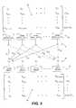
- FIG. 5is a block diagram illustrating an example matrix of a transmitted sequence structure and an example matrix of a received sequence structure using the modulator/demodulator arrangement shown in FIG. 1 .
- FIG. 6illustrates a three-dimensional representation of the received sequence structure in detail.
- FIG. 7is a block diagram illustrating an example embodiment of one of the OFDM demodulators shown in FIG. 1 .
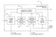
- FIG. 8is a block diagram illustrating an example embodiment of the synchronization circuit shown in FIG. 7 .
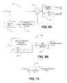
- FIGS. 9A and 9Bare block diagrams illustrating example embodiments of the coarse time synchronization circuit shown in FIG. 8 .
- FIG. 10is a block diagram illustrating an example embodiment of the first frequency offset estimation circuit shown in FIG. 8 .
- FIG. 11is a block diagram illustrating an example embodiment of the fine time synchronization circuit shown in FIG. 8 .
- FIG. 12is a block diagram illustrating an example embodiment of the second frequency offset estimation circuit shown in FIG. 8 .
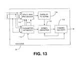
- FIG. 13is a block diagram illustrating an example embodiment of the decoder shown in FIG. 1 .
- FIG. 1an example embodiment of a Multi-Input, Multi-Output (MIMO) Orthogonal Frequency Division Multiplexing (OFDM) communication system 6 of the present invention is shown.
- the communication system 6 in this example embodimentmay be implemented as a wireless system for the transmission and reception of data across a wireless channel 19 .
- the communication system 6may be part of a wireless Local Area Network (LAN) system or wireless Metropolitan Area Network (MAN) system, cellular telephone system, or other type of radio or microwave frequency system incorporating either one-way or two-way communication over a range of distances.
- the communication system 6may transmit in a range from 2 to 11 GHz, for example, such as in the unlicensed 5.8 GHz band using a bandwidth of about 3–6 MHz.
- the present inventionis also possible for the present invention to be used in a system that comprises an array of sub-channel communication links that carry a number of signals transmitted by a number of transmitting elements to each of a number of receiving elements.
- communication linkssuch as wires in a wiring harness or some alternative wired transmission system, for example, could be used over the distance between a data source and a receiver.
- a transmitter 8transmits signals across the wireless channel 19 and a receiver 10 receives the transmitted signals.
- the transmitter 8comprises a data source 12 , which provides the original binary data to be transmitted from the transmitter 8 .
- the data source 12may provide any type of data, such as, for example, voice, video, audio, text, etc.
- the data source 12applies the data to an encoder 14 , which encodes the data to allow for error correction.
- the encoder 14further processes the data so that certain criterion for space-time processing and OFDM are satisfied.
- the encoder 14separates the data onto multiple paths in the transmitter 8 , each of which will hereinafter be referred to as a transmit diversity branch (TDB).
- TDBtransmit diversity branch
- the separate TDBsare input into OFDM modulators 16 , each of which modulates the signal on the respective TDB for transmission by the transmitting antennas 18 .
- the present inventionmay be used in a Single-Input, Single-Output (SISO) system, which may be considered as a special case of MIMO wherein the number of transmitting and receiving antennas is one.
- SISOSingle-Input, Single-Output
- separation of the data by the encoder 14is not necessary since only one OFDM modulator 16 and antenna 18 is used.
- Each frame along each TDBis output from a respective OFDM modulator 16 .
- any number of OFDM modulators 16may be used.
- the number of OFDM modulators 16 and respective transmitting antennas 18may be represented by a variable “Q.”
- the OFDM modulators 16modulate the respective frames at specific sub-carrier frequencies and respective transmitting antennas 18 transmit the modulated frames over the channel 19 .
- a number “L” of receiving antennas 20receives the transmitted signals, which are demodulated by a number L of respective OFDM demodulators 22 .
- the number Lmay represent any number and is not necessarily the same as the number Q.
- the number Q of transmitting antennas 18may be different from the number L of receiving antennas 20 , or they may alternatively be the same.
- the outputs of the demodulators 22are input into a decoder 24 , which combines and decodes the demodulated signals.
- the decoder 24outputs the original data, which may be received by a device (not shown) that uses the data.
- the communication system 6may comprise one or more processors, configured as hardware devices for executing software, particularly software stored in computer-readable memory.
- the processorcan be any custom made or commercially available processor, a central processing unit (CPU), an auxiliary processor among several processors associated with a computer, a semiconductor based microprocessor (in the form of a microchip or chip set), a macroprocessor, or generally any device for executing software instructions.
- Suitable commercially available microprocessorsare as follows: a PA-RISC series microprocessor from Hewlett-Packard Company, an 80 ⁇ 86 or Pentium series microprocessor from Intel Corporation, a PowerPC microprocessor from IBM, a Sparc microprocessor from Sun Microsystems, Inc, a 68xxx series microprocessor from Motorola Corporation, or a 67xxx series Digital Signal Processor from the Texas Instruments Corporation.
- the communication system 6can be stored on any computer-readable medium for use by or in connection with any computer-related system or method.
- a computer-readable mediumis an electronic, magnetic, optical, or other physical device or means that can contain or store a computer program for use by or in connection with a computer related system or method.
- the communication system 6can be embodied in any computer-readable medium for use by or in connection with an instruction execution system, apparatus, or device, such as a computer-based system, processor-containing system, or other system that can fetch the instructions from the instruction execution system, apparatus, or device and execute the instructions.
- a “computer-readable medium”can be any means that can store, communicate, propagate, or transport the program for use by or in connection with the instruction execution system, apparatus, or device.
- the computer-readable mediumcan be, for example but not limited to, an electronic, magnetic, optical, electromagnetic, infrared, or semiconductor system, apparatus, device, or propagation medium. Examples of the computer-readable medium include the following: an electrical connection having one or more wires, a portable computer diskette, a random access memory (RAM), a read-only memory (ROM), an erasable programmable read-only memory (EPROM, EEPROM, or Flash memory), an optical fiber, and a portable compact disc read-only memory (CDROM).
- the computer-readable mediumcould even be paper or another suitable medium upon which the program is printed, as the program can be electronically captured, via for instance optical scanning of the paper or other medium, then compiled, interpreted or otherwise processed in a suitable manner if necessary, and then stored in a computer memory.
- the communication system 6can be implemented with any or a combination of the following technologies, which are each well known in the art: one or more discrete logic circuits having logic gates for implementing logic functions upon data signals, an application specific integrated circuit (ASIC) having an appropriate combination of logic gates, a programmable gate array (PGA), a field programmable gate array (FPGA), etc.
- ASICapplication specific integrated circuit
- PGAprogrammable gate array
- FPGAfield programmable gate array
- FIG. 2shows details of an example embodiment of the encoder 14 shown in FIG. 1 .
- the encoder 14may be configured such that data from the data source 12 is encoded by a channel encoder 26 , which adds parity to the original data to produce channel encoded data.
- the channel encoder 26encodes the data using a scheme that is recognized by the decoder 24 of the receiver 10 and enables the decoder 24 to detect errors in the received data. Errors may arise as a result of environmental conditions of the channel 19 or noise inadvertently added by the transmitter 8 or receiver 10 .
- the encoder 14further includes a symbol mapper 28 , which maps the channel-encoded data into data symbols.
- the symbol mapper 28groups a predetermined number of bits such that each group of bits constitutes a specific symbol chosen from a pre-determined alphabet.
- the symbol mapper 28further lays out a stream of data symbols within the structure of a frame.
- the encoder 14further includes a space-time processor 30 that processes the data symbol stream received from the symbol mapper 28 and outputs the processed data symbols via the respective TDBs.
- the space-time processor 30encodes the data symbol stream in a manner such that the receiver 10 is capable of decoding the signals.
- the data symbols in the TDBsare distributed over Q lines that will eventually be transmitted at precise frequencies spaced apart from each other by a predetermined difference in frequency. By providing a specific frequency difference between the multiple sub-channels, orthogonality can be maintained, thereby preventing the OFDM demodulators 22 from picking up frequencies other than their own designated frequency.
- Each TDBprovides an input to a respective adder 34 .
- the other input into each of the adders 34is connected to the output of a pilot/training symbol inserter 32 , which provides pilot symbols and training symbols to be inserted into the frames on the TDBs.
- Symbols inserted periodically within the data symbolswill be referred to herein as “pilot symbols.” These periodic pilot symbols may be inserted anywhere in the stream of the data symbols. If a continuous burst of symbols is inserted by the pilot/training symbol inserter 32 , this type of symbol will be referred to herein as “training symbols” which constitute the preamble.
- the training symbolspreferably are inserted at the beginning of the frame. However, the training symbols may be inserted onto the frame in a location other than at the beginning of the frame, such as at the end or in the middle of the frame.
- the pilot/training symbol inserter 32may be configured so that it is capable of storing multiple sets of training symbols or pilot symbols. In this case, a particular set may be selected, for example, based on desirable communication criteria established by a user.
- the training symbols for each respective sub-channelmay preferably be unique to the particular sub-channel. In order to accommodate amplitude differences between the sub-channels, the training symbols may be designed and adjusted to maintain a constant amplitude at the output of each sub-channel.
- Training symbolsare preferably transmitted once for every frame. Training symbols are used for periodic calibration (synchronization and channel parameter estimation) whereas pilot symbols are used for minor adjustments to deal with the time-varying nature of the channel.
- the training symbolsmay be indicative of calibration values or known data values. These calibration values or known values may be transmitted across the channel, and used to calibrate the communication system 6 . Any necessary refinements may be made to the communication system 6 if the received calibration values do not meet desirable specifications.
- the training symbolsmay be used as specific types of calibration values for calibrating particular channel parameters. By initially estimating these channel parameters, offsets in the time domain and frequency domain may be accounted for so as to calibrate the communication system 6 .
- the training sequencemay or may not bypass an Inverse Discrete Fourier Transform (IDFT) stage 38 , which is a part of the embodiment of the OFDM modulator 16 of FIG. 3 .
- a training sequence that bypasses the IDFT stage 38 and is directly input into a digital to analog converter (DAC) 44is referred to herein as a directly modulatable training sequence.
- Examples of such training sequencesmay be “chirp-like” sequences. These sequences cover each portion of the bandwidth used by the communication system 6 . Hence, channel response can be easily determined.
- a chirp sequence in the time domainis given by the equation:
- s nrefers to a time domain signal on the side of the transmitter 8 .
- Frequency domain signals on the transmitter sidewill hereinafter be referenced by capital letters S k .
- Time and frequency domain signals on the receiver sidewill hereinafter be written as r n and R k , respectively.
- chirp-like sequencemay be Frank-Zadoff sequences, Chu sequences, Milewski sequences, Suehiro polyphase sequences, and sequences given by Ng et al.
- the channel parametersmay be estimated.
- a training sequencemay be generated by modulating each of the symbols on the TDBs with a known sequence of symbols in the frequency domain and passing the symbols through the IDFT stage 38 .
- a known sequence of symbolsis obtained from an alphabet which has its constituents on the unit circle in the complex domain and such that the resultant sequence in the time domain has a suitable Peak to Average Power Ratio (PAPR).
- PAPRPeak to Average Power Ratio
- An alphabet in communication systemsis defined as a finite set of complex values that each of the symbols can assume. For example, an alphabet of a binary phase shift keying (BPSK) system consists of values +1 and ⁇ 1 only.
- BPSKbinary phase shift keying
- An alphabet for a quaternary phase shift keying (QPSK) systemconsists of the values 1+j, ⁇ 1+j, 1 ⁇ j, and ⁇ 1 ⁇ j.
- the training sequencemay be generated by modulating each of the tones of the OFDM block using a BPSK alphabet, which consists of symbols +1 and ⁇ 1.
- the synchronization schememay be very general such that any known sequence having suitable properties, such as low PAPR, may be used to form the training sequence.
- the adders 34add the training symbols and pilot symbols to the frame.
- Other embodimentsmay be used in place of the adders 34 for combining the training symbols and pilot symbols with the data symbols in the frame.
- the adders 34may include additional inputs to allow for flexibility when adding the pilot/training symbols or in the combining of multiple training symbols or even selectable training symbols. After the training symbols are inserted into frames on the respective TDBs, the frames are output from the encoder 14 and input in respective OFDM modulators 16 .
- FIG. 3shows an example embodiment of an OFDM modulator 16 , which receives signals along one of the TDBs.
- the number of OFDM modulators 16is preferably equal to the number of transmitting antennas 18 .
- SISO systemsthere is only one OFDM modulator 16 and one transmitting antenna 18 .
- MIMO systemsthere may be any number of OFDM modulators 16 and transmitting antennas 18 .
- the respective signal from the encoder 14is input into a serial-to-parallel converter 36 of the OFDM modulator 16 .
- the serial-to-parallel converter 36takes N symbols received in a serial format and converts them into a parallel format.
- the variable Nwill be referred to herein as the blocksize of the OFDM symbol.
- the N parallel symbolsare processed by an Inverse Discrete Fourier Transform (IDFT) stage 38 , which transforms the frequency signals to the time domain.
- IFTInverse Discrete Fourier Transform
- a methodis proposed herein to design the training symbols such that the transforms of all the sequences from the IDFT stage 38 will have a constant magnitude.
- PAPRpeak to average power ratio
- the output from the IDFT stage 38is input into a cyclic prefix inserter 40 , which inserts an additional number of samples for every N samples.
- the number of samples inserted by the cyclic prefix inserter 40will be referred to herein by the variable “G.”
- the G samplesare intended to be inserted as guard intervals to separate the N adjacent data symbols from each other in time by a separation adequate to substantially eliminate Inter Symbol Interference (ISI).
- the cyclic prefix inserter 40repeats G samples from a latter portion of the N samples output from the IDFT stage 38 and inserts the G samples as a prefix to each of the data samples.
- the time length of the cyclic prefixis greater than the maximum time delay of a transmitted signal across the channel 19 .
- the nature of the channel 19may be susceptible to a variation in the delay time from the transmitted antennas 18 to the receiving antennas 20 , it may be desirable to increase, or even double, the length of cyclic prefixes of the preamble to ensure that the time delay of the channel does not exceed the time of the cyclic prefix, thereby eliminating ISI.
- the G+N samplesherein referred to as an OFDM symbol, are then converted from a parallel format to a serial format using parallel-to-serial converter 42 , and then inputted to a digital-to-analog converter (DAC) 44 for conversion into analog signals.
- the output from the DAC 44is input into a mixer 48 .
- a local oscillator 46provides a signal having the carrier frequency to the other input of the mixer 48 to up-convert the respective OFDM symbol from baseband to RF.
- the frameis amplified by an amplifier 50 .
- an amplifier 50may be backed off to prevent it from going into its non-linear region.
- the present inventionmay provide certain specific sequences that can be used in order to make the PAPR minimal or unity.
- Each OFDM modulator 16preferably comprises the same components as the OFDM modulator 16 shown in FIG. 3 .
- Other techniques for designing the OFDM modulators 16may be used in order to transmit the multiple frames across the channel 19 with minimal interference.
- Each frame output from the respective OFDM modulator 16is transmitted by a respective antenna 18 .
- the antennas 18may be spaced apart from each other by any desirable separation. For example, the separation distance may be in a range from a few millimeters to several meters.
- FIG. 4illustrates an example of a frame 52 that is transmitted across the channel 19 from the transmitting antennas 18 to the receiving antennas 20 .
- the frame 52comprises a preamble 54 comprising a number of training symbols N I and cyclic prefixes G.
- the preamble 54is inserted by the pilot/training symbol inserter 32 as mentioned above.
- the data frame 52comprises a data portion 56 consisting of a plurality of OFDM data symbols N and cyclic prefixes G, which are inserted before each of the OFDM data symbols N.
- the pilot/training symbol inserter 32further inserts pilot symbols (not shown) intermittently within the OFDM data symbols N.
- the task of the preamble 54 and training symbols N I in the frameis to help the receiver 10 identify the arrival of the frame 52 and hence perform time synchronization, frequency synchronization, and channel parameter estimation.
- the preamble 54in general, consists of Q or more training symbols, wherein each training symbol has a length of G+N I samples in time.
- N Imay be 1 ⁇ 4 N. If no predetermined N I has been established, the variable N I may be given the value equal to N.
- the training symbol lengthmay be shorter than the length of the symbols in the data portion 56 , which has a length of G+N samples.
- FIG. 5shows a portion of the MIMO OFDM communication system 6 of FIG. 1 along with details of a signal transmission matrix S and a received demodulated OFDM sample matrix R.
- Ris a T ⁇ L received demodulated OFDM sample matrix
- ⁇is a Q ⁇ L matrix of channel coefficients that are indicative of the characteristics of the channel across which the signals are transmitted
- Sis a TX Q signal transmission matrix
- Wis a T ⁇ L noise matrix that corrupts and distorts the received sample matrix R.
- Tmay or may not be equal to Q and does not affect the synchronization procedure. Hence, for simplicity, the assumption is made herein that T is equal to Q.
- the signal transmission matrix S shown in FIG. 5consists of Q OFDM symbols that are simultaneously transmitted from Q transmit antennas 18 over Q or more OFDM symbol periods (T s ). For example, at a first time instance t, the OFDM symbols S 1 , S 2 , . . . S Q are transmitted from the first to the Qth antennas 18 . At a second time instance t+T S , the OFDM symbols S Q+1 , S Q+2 , . . . S 2Q are transmitted from the same antennas 18 . The OFDM symbol transmissions are repeated at each time instance until all of the OFDM symbols of the matrix S have been transmitted.
- the S matrixconsists of Q or more training symbols, each of which is less than or equal to the length of an OFDM symbol in the time dimension.
- the training symbolsare simultaneously transmitted from the transmitting antennas 18 as represented by equations (1) and (2), wherein the different antennas correspond to the space dimension.
- the S matrixconsists of Q or more data symbols each occupying an OFDM symbol in the time dimension.
- the pilot/training symbol inserter 32inserts the pilot symbols within the data symbols.
- the data symbolsare encoded, modulated, and transmitted from the transmitting antennas 18 .
- Each signal transmission matrix S of Q ⁇ Q OFDM symbolsare transmitted over the communication channel 19 , which naturally comprises a matrix of channel coefficients ⁇ .
- the communication channel 19includes characteristics that distort and degrade the transmitted signal.
- the communication systemadds noise terms represented by the matrix W, before the signal transmission matrix S is received at the L receive antennas 20 . The addition of noise further degrades the system performance.
- FIG. 5further illustrates how each of the L receiving antennas 20 receives each of the Q transmitted signals.
- the first receive antenna 20receives OFDM signals over channel impulse responses h 1I , h 2I , h 3I . . . h QI from the first to the Qth transmitting antennas 18 , respectively.
- the term h i, jrefers to the channel impulse response from the i th transmit to the j th receive antenna in the time domain.
- the last receive antenna 20receives the transmitted signals over the channel impulse responses h 1L , h 2L , h 3L , . . . h QL from the first to the Qth transmitting antennas 18 , respectively.
- only the signals received at the first and last receiving antennas 20are shown. However, it should be understood that each receiving antenna 20 receives the signals transmitted from the Q transmitting antennas 18 .
- the received signalsare demodulated by the respective OFDM demodulators 22 , which provide the received demodulated OFDM sample matrix R.
- the samples R 1 , R Q+1 , . . . R (L ⁇ I)Q+1are received.
- the samples R 2 , R Q+2 . . . R (L ⁇ 1)Q+2are received.
- the samplesare received at each time instance until all of the samples in the received demodulated OFDM sample matrix R are received. It should be noted that the time instances used for the matrices S and R are given the same variable, but, in essence, a delay occurs as is well known in the art.
- a significant task of the receiver 10is to estimate the time of arrival of the transmitted signal. This process is called “time synchronization.”
- time synchronizationIn addition to time synchronization, OFDM systems typically require frequency synchronization as well. Because there usually exists a certain difference between the local oscillator frequencies of the transmitter and the receiver, the received signals experience a loss of sub-carrier orthogonality, which should typically be corrected in order to avoid degradation in system performance.
- FIG. 6shows a detailed illustration of the received demodulated OFDM sample matrix R which consists of L columns and Q or more rows of OFDM symbols with respect to space and time, respectively.
- the matrix Rconsists of three dimensions, namely space, time and frequency.
- the frequency axisindicates the amplitude of the frequency component received at each receiving antenna 20 from each transmitting antenna 18 .
- Each of the matrices R and ⁇can be seen to consist of N matrices of dimension Q ⁇ L or Q ⁇ L vectors of length N.
- the training symbol lengthmay be equal to the data symbol length.
- the length of the training symbol in the preamblemay be (N+G) since it is possible to estimate the characteristics of the channel even if the training symbol length is shortened to N I +G such that (N I +G) ⁇ (N+G).
- the range to be establishedmay depend upon the characteristics of the channel to be estimated also.
- Transmission of the training sequence of length N Icorresponds to exciting every Ith sub-channel of an OFDM signal having a block size N. This means that no information is transmitted on the remaining (1 ⁇ 1/I)N sub-channels and the estimates of the channel for the sub-channels are derived from the ones that actually include information. This may result in a poor performance and hence it is left to the system designer to determine the length of the preamble.
- the sub-channels of the transmit sequence that bear no informationare said to be zero-padded.
- the training sequence of length N Imay be generated by first modulating every Ith sub-channel of the OFDM block by a known sequence of symbols and zero padding the rest. An N-point IDFT is taken to obtain N samples in the time domain, and finally only the first N I samples along with its cyclic prefix are transmitted. At the receiver after synchronization, the samples corresponding to the training sequence of length N I are repeated I times before being demodulated by the OFDM demodulators.
- many more sub-channelsare zero padded to reduce the interference between the adjacent bands and to facilitate the system implementation. For example, in the systems based on the IEEE 802.16a/b standard, a total of 56 tones or sub-carriers are zero padded.
- the training sequence structure in the frequency domainis represented by its signal transmission matrix, which is configured in such a way so as to have certain properties that aid in synchronization and channel estimation.
- the signal transmission matrix for a 2 ⁇ 2 systemmay be of the form:
- the signal transmission matrix S for a 4 ⁇ 4 systemmay be of the form:
- S k[ S 1 , k S 1 , k S 1 , k S 1 , k - S 1 , k S 1 , k - S 1 , k S 1 , k S 1 , k - S 1 , k S 1 , k S 1 , k - S 1 , k S 1 , k - S 1 , k S 1 , k S 1 , k S 1 , k S 1 , k S 1 , k S 1 , k ] , ( 2 )
- S 1is the sequence in the frequency domain that has certain properties that satisfy the system requirements.
- the signal transmission matrix S for a 3 ⁇ 3 systemmay be of the form:
- the rows of the signal transmission matrixrepresent the time dimension, the columns represent the space dimension and the index k represents the frequency dimension or the corresponding sub-carrier.
- the transmitter 8may create the matrix S k such that it is unitary. If the vectors of the training sequences are derived from the points along the unit circle in the complex domain then the signal transmission matrices S k shown in (1) and (2) are unitary. Besides making each of the transmission matrices S k unitary, it also facilitates the system implementation and maintains a low PAPR of the sequence structure in the time domain. This is because the signal transmission matrices in the training mode and the data mode are exactly alike, which further simplifies the system implementation. The transmission of a unitary matrix aids in parameter estimation, as is described below.
- the L number of receiving antennas 20receive the Q number of transmitted signals and provide the received signals to respective OFDM demodulators 22 , which down-convert the signal back to baseband.
- the L number of receiving antennas 20are separated by a distance such that the received signals have minimum correlation and are as independent from each other as possible.
- the outputs from the L number of OFDM demodulators 22are input into a decoder 24 , which combines the multiple signals and decodes them.
- the decoder 24removes any correctable noise and distortion errors, as will be described below, and outputs signals representative of the original data.
- FIG. 7illustrates an example embodiment of one of the OFDM demodulators 22 of the receiver 10 .
- Received signals from the receiving antenna 20are input into a pre-amplifier 57 , which amplifies the received signals to a level at which further processing may be performed.
- the output of the pre-amplifier 57is connected to a mixer 58 .
- a local oscillator 59provides a signal to the mixer 58 having a frequency designed to demodulate the received amplified signal.
- the demodulated signalis then output to an analog-to-digital converter (ADC) 60 , which converts the analog signals into discrete time samples.
- ADCanalog-to-digital converter
- OFDMtypically requires substantial synchronization in time as well as in frequency in order that transmitted signals can be recovered with adequate accuracy.
- Time synchronizationinvolves determining the best possible time for the start of the received frame to closely match the start of the transmitted signal.
- Frequency synchronizationinvolves maintaining orthogonality of the respective sub-carrier frequencies.
- Orthogonalityrefers to a condition of the sub-carrier frequencies wherein the “inner product” of the signals at different sub-carrier frequencies is zero.
- the time domain sequences s 2,nare transmitted.
- ICIInter Carrier Interference
- the synchronization circuit 61corrects this loss of sub-channel orthogonality by finding an estimate of the difference between the frequencies of the local oscillators 46 of the transmitter 8 and the frequencies of the local oscillators 59 of the receiver 10 .
- the synchronization circuit 61further corrects these frequency difference estimates.
- the synchronization circuit 61will now be explained with reference to FIG. 8 .
- the input to the synchronization circuit 61connected to the output of the ADC 60 , is input into a coarse time synchronization circuit 66 and a frequency offset correction circuit 74 .
- the coarse time synchronization circuit 66determines the approximate start time of each received block of N+G samples by estimating the approximate starting time of the OFDM frame.
- the coarse time synchronization circuit 66sends the coarsely synchronized signals to a first frequency offset estimation circuit 68 .
- the coarse time synchronization circuit 66sends a second output to the frequency offset correction circuit 74 and a third output back to the pre-amplifier 57 for altering the gain of the pre-amplifier 57 .
- the first frequency offset estimation circuit 68estimates the frequency offset to within one-half of the sub-carrier spacings.
- An output from the first frequency offset estimation circuit 68is sent to the frequency offset correction circuit 74 .
- the frequency offset correction circuit 74performs an initial correction of the frequency offset, utilizing the signals received from the ADC 60 , coarse time synchronization circuit 66 , and the first frequency offset estimation circuit 68 .
- the frequency offset correction circuit 74sends the initial frequency corrected samples to a cyclic prefix remover 62 , which is shown in FIG. 7 .
- the cyclic prefix remover 62removes the cyclic prefixes from the frames and sends the symbols, with the cyclic prefixes removed, to a serial-to-parallel converter 63 .
- the serial-to-parallel converter 63converts the serial stream to a parallel format and sends the parallel data to a Discrete Fourier Transform (DFT) stage 64 .
- DFT stage 64converts the time domain samples to the frequency domain, and returns an output to the synchronization circuit 61 to refine the synchronization in the time and frequency domain.
- the output from the DFT 64travels to a second frequency offset estimation circuit 70 and a fine time synchronization circuit 72 .
- the second frequency offset estimation circuit 70receives the estimation of the frequency offset to within one-half the sub-carrier spacing form the first frequency offset estimation circuit 68 and the frequency domain samples from the DFT 64 . Using these input signals, the second frequency offset estimation circuit 70 provides an estimation of the frequency offset to an integer multiple of sub-carrier spacings.
- the second frequency offset estimation circuit 70provides an output to the local oscillator 59 for adjusting the frequency of the local oscillator 59 to the frequency of the local oscillator 46 of the transmitter 8 .
- the second frequency offset estimation circuit 70sends a second output to the frequency offset correction circuit 74 , which may further correct the frequency offset during a second stage, based on the offset estimated by the second frequency offset estimation circuit 70 .
- Both the frequency offset correction circuit 74 and the second frequency offset estimation circuit 70send outputs to the fine time synchronization circuit 72 , which calculates a more accurate start time of the received frame.
- Outputs from the frequency offset correction circuit 74 and fine time synchronization circuit 72are sent to the cyclic prefix remover 62 , which receives the signals that are further synchronized during the second stage of the synchronization circuit 61 .
- the synchronization circuit 61may be utilized as many times as necessary to accurately synchronize the receiver 10 in the time and frequency domains.
- the known calibration valuesmay be transmitted by the transmitter 8 for an amount of time until the synchronization circuit 61 has developed an accurate correction to compensate for time variations and frequency offsets that may be inherent in the communication system 6 and channel 19 .
- frames carrying the user's data symbolsmay be transmitted with confidence that time and frequency synchronization will allow acceptable reception of the transmitted signals.
- newly received symbols sent to the synchronization circuit 61may bypass the synchronization and estimation circuits and pass through the frequency offset correction circuit 74 to synchronize the new symbols. Therefore, as time passes, the synchronization circuit 61 may make slight adjustments to account for any changes in the communication system 6 , but may reach a steady state when the communication system 6 does not change.
- the coarse time synchronization circuit 66determines the approximate start time of each received block of N+G samples.
- the coarse time synchronization circuit 66may use circuitry which takes into account the periodicity inserted into the training symbol, or in other words, the periodic occurrences of the inserted cyclic prefixes in the data frame.
- the coarse time synchronization circuit 66detects the location of the cyclic prefixes by observing the repetitious nature of the G samples. To reiterate, the G samples repeat a portion of the N samples, as explained above.
- the coarse time synchronization circuit 66may comprise circuitry capable of performing a technique that is hereinafter referred to as “auto-correlation.”
- the phase output from the auto-correlation circuitmay be used in the example embodiment of the first frequency offset estimation circuit 68 , as is described in more detail below.
- the technique of auto-correlationis accomplished by comparing the samples of a data stream with samples of the same data stream that are delayed by the number of samples N I .
- FIG. 9AAn example embodiment of an auto-correlation circuit 75 is shown in FIG. 9A .
- a received frameis demodulated into a data stream r n , which is input into a mixer 76 and a delay circuit 77 .
- the delay circuit 77delays the data stream by N I samples such that a second input into the mixer 76 will be offset by N I samples.
- the delayed data streamis processed by a complex conjugation circuit 78 , which outputs the processed data stream to the second input of the mixer 76 .
- the mixer 76compares the data stream r n with the delayed and processed data stream. Since the delayed data stream is delayed by N I samples, the mixer compares the start of the preamble at the first G sample with a sample that is delayed N I from the start of the preamble. If the comparison between the data stream r n and the delayed data stream reveals an alignment of the G samples of the cyclic prefix with the last G samples of the training symbol N I , then the mixer 76 outputs a constructively added waveform. The output of the mixer 76 is input into a summing circuit 79 , which sums the output of the mixer 76 over G samples and provides the magnitude and phase of the sum.
- the auto-correlation operationcan be represented using the equation:
- the coarse time synchronization circuit 66may also correct any undesirable fluctuations in the amplitude of the signals received by the receiver 10 . Signals experiencing long-term amplitude fluctuations may be corrected by an automatic gain control (AGC) circuit, which may be part of the coarse time synchronization circuit 66 .
- AGCautomatic gain control
- the AGC circuitmay detect variations in the signal amplitudes and provide feedback signals to the pre-amplifier 57 in order to maintain the received signals at a constant magnitude.
- an embodiment of an AGC circuit 80comprises an instantaneous energy calculator 82 , which calculates the instantaneous energy using the formula:
- Mcan be any number large enough to average long term fluctuations in the OFDM signal.
- Mmay be equal to 10(N+G).
- the coarse time synchronization circuit 66corrects short-term fluctuations in the signals by utilizing the training symbols, pilot symbols, and the instantaneous energy value p n generated by the AGC circuit 80 . After the coarse time synchronization circuit 66 determines an approximate starting time, a more precise time synchronization is achieved by utilizing the fine time synchronization circuit 72 , which preferably follows in sequence after a frequency offset estimation operation, as will be described below.
- the coarse time synchronization circuit 66outputs the coarsely synchronized signals to the first frequency offset estimation circuit 68 ( FIG. 8 ) for carrying out the first step of frequency offset estimation and correction.
- frequency synchronizationis preferably carried out in two steps.
- the phase output from the auto-correlation circuit 75is input into an offset estimation circuit 86 .
- the offset estimation circuit 86estimates the frequency offset using a formula that may be expressed by:
- the first frequency offset estimation circuit 68estimates the fractional portion of the frequency offset.
- the frequency offset of the integer multiples of the subcarrier spacingsis performed by the second frequency offset estimation circuit 70 by performing a cyclic cross-correlation in the frequency domain.
- the cyclic cross-correlationis made possible by the fact that the training sequence structure is designed such that the same sequence is transmitted from all the transmitting antennas 18 in the first training symbol period.
- the second frequency offset estimation circuit 70receives feedback from the output of a Discrete Fourier Transform (DFT) stage 64 ( FIG. 7 ), which converts the signal into the frequency domain, and is compared (cross-correlated) with the training symbol that was transmitted.
- DFTDiscrete Fourier Transform
- the second frequency offset estimation circuit 70can also be used to provide a feedback signal to correct and adjust the frequency of the local oscillator 59 .
- FIG. 11illustrates an example of an embodiment of the way in which the second frequency offset estimation circuit 70 shown in FIG. 8 can be configured.
- An output from the DFT 64is input as a frequency domain received symbol R I to a buffer 88 , which stores in memory N samples. Outputs from the buffer 88 are input into N mixers 90 . Sequences S I from the first frequency offset estimation circuit 68 are input into another buffer 92 , which stores the sequence S I having a length of N samples. Sequence S I is constructed by first repeating the sequence s I in the time domain I times and then taking an N-point FFT of the repeated sequence. Outputs from the buffer 92 are input into complex conjugation circuits (CCCs) 94 for performing complex conjugation operations. The outputs of the CCCs 94 are input into second inputs into the mixers 90 , which mixes the two sets of inputs. The outputs from the mixers 90 are sent to a summing circuit 96 , which provide a function having the equation:
- the index k at which ⁇ achieves its maximumgives the frequency offset estimate of the integral number of sub-carrier spacings.
- the output from the summing circuit 96is sent to the frequency offset correction circuit 74 ( FIG. 8 ), the fine time synchronization circuit 72 , and the local oscillator 59 .
- the frequency offset correction circuit 74further corrects the frequency difference to synchronize the frequency with respect to the integer multiples.
- the local oscillator 59responds by adjusting the sub-carrier frequency to minimize the frequency offset.
- the frequency offset correction circuit 74receives the estimates of the frequency offset from the first frequency offset estimation circuit 68 and the second frequency offset estimation circuit 70 . In response to the estimates in the frequency offset, the frequency offset correction circuit 74 can correct the frequency offset in discrete time or partly in discrete time and partly by sending the correction factor to the local oscillator 59 .
- Fine time synchronizationcan then be achieved by using the fine time synchronization circuit 72 to find the start of the useful portion of the OFDM block to within a few samples. Fine time synchronization can be performed by cross-correlating the transmitted training symbols with the received frequency offset corrected signals from the frequency offset correction circuit 74 and by recognizing a predetermined pattern. If different sequences are transmitted from different antennas, then Q such correlation circuits are needed and the magnitudes of their outputs are summed together. The peak of the summed magnitudes will indicate the fine time synchronization instant. In the example of the transmission matrix structure provided in equations (1) and (2), the same sequence is transmitted from all the transmitting antennas 18 in the first OFDM symbol period. Hence, for this case, only one such correlation circuit is required and the sequence that is stored in the buffer is the time domain counterpart of the sequence S 1 .
- sequences with special propertiescan be transmitted from each antenna to further enhance the performance of the fine time synchronization circuit 72 .
- These propertiescould include the orthogonal nature of the transmitted sequences or any other variation on the sequences to be transmitted from different antennas.
- FIG. 12illustrates an example embodiment of the fine time synchronization circuit 72 .
- a buffer 100comprises a memory device for storing N I samples.
- the buffer 100receives the received samples r n from the second frequency offset estimation circuit 70 .
- a second buffer 104stores the time domain sequence s I having the length N I , wherein S I is the replica of the original transmitted sequence or a semblance of the transmitted sequence s 1 .
- Each output from the buffer 100is input into a first input of a number of N I mixers 102 .
- the outputs from the buffer 104are input into a number of N I CCCs 106 , which perform complex conjugate operations on the outputs from buffer 104 .
- Each output from the CCCs 106is input into a second input of the N I mixers 102 .
- the N I number of combined signals from the mixers 102are input into a summing circuit 108 , which sums the combined signals using equation:
- Fine time synchronizationis achieved at a time instant n when the function ⁇ attains a value greater than a predetermined threshold.
- the output from the summing circuit 108represents the output of the synchronization circuit 61 and is sent to a cyclic prefix remover 62 ( FIG. 7 ).
- the performance of the fine time synchronization circuit 72is dependent on the frequency offset estimation and correction. Presence of any frequency offset hampers the performance of the fine time synchronization circuit 72 .
- the timing informationmay be derived directly from the coarse time synchronization circuit 66 .
- coarse time synchronizationcan be modified to provide better estimates by averaging the results of the coarse time synchronization circuits from different OFDM demodulators and over different times.
- the fine time synchronization circuit 72provides an optimal time instant of the start of the received OFDM frame.
- the communication system 6may either employ L such synchronization circuits 61 , one for each OFDM demodulator 22 or it may employ certain parts of the synchronization circuit for all the OFDM demodulators 20 and certain parts that are common to the entire receiver 10 .
- the OFDM modulators 22may include individual time synchronization circuits 66 and 72 and frequency offset correction circuit 74 , but may share common frequency offset estimation circuits 68 and 70 .
- the receiver 10may simply comprise a single synchronization circuit 61 .
- the frequency and time synchronized informationis provided to the cyclic prefix remover 62 , which removes the cyclic prefixes inserted between each block of N symbols.
- the blocks of N samplesare then serial-to-parallel converted using serial-to-parallel converter 63 and the parallel signals are input to the DFT stage 64 , which converts the time domain samples back to the frequency domain, thus completing synchronization and demodulation by the OFDM demodulators 22 .
- the L number of demodulated signals from each of the L number of OFDM demodulators 22are then input into the decoder 24 , which processes the demodulated signals.
- the decoder 24may be configured in the manner shown in the example embodiment of FIG. 13 .
- the decoder 24comprises a space-time processor 110 and a parameter estimator 112 . Both the space-time processor 110 and parameter estimator 112 receive the signals from each of the L number of OFDM demodulators 22 .
- An output from the parameter estimator 112is input into a symbol demapper 116 and a set of outputs is input into the space-time processor 110 .
- the output of the space-time processor 110is converted from parallel to serial by a parallel-to-serial converter 114 and then input to the symbol demapper 116 , which maps the symbols from the predetermined alphabet back to the data bits.
- the output from the symbol demapper 116is input into a channel decoder 118 .
- the channel decoder 118decodes the data symbols by checking the parity that was added to the symbols prior to transmission. Thus, the channel decoder 118 detects and corrects errors in the data symbols and outputs the data in its original form.
- the communication system 6 of the present inventioncan be implemented in hardware, software, firmware, or a combination thereof.
- the communication system 6can be implemented in software or firmware that is stored in a memory and that is executed by a suitable instruction execution system.
- the synchronization systemcan be implemented with any or a combination of the following technologies, which are all well known in the art: a discrete logic circuit having logic gates for implementing logic functions upon data signals, an application specific integrated circuit (ASIC) having appropriate combinational logic gates, a programmable gate array (PGA), a field programmable gate array (FPGA), digital signal processor (DSP), etc.
Landscapes
- Engineering & Computer Science (AREA)
- Computer Networks & Wireless Communication (AREA)
- Signal Processing (AREA)
- Radio Transmission System (AREA)
Abstract
Description
where j is given by √{square root over (−1)} and is used to denote the quadrature component of the signal. It should be noted that the term snrefers to a time domain signal on the side of the
Rk,T×L=Sk,T×Qηk,Q×L+Wk,T×L
where R is a T×L received demodulated OFDM sample matrix, η is a Q×L matrix of channel coefficients that are indicative of the characteristics of the channel across which the signals are transmitted, S is a TX Q signal transmission matrix, and W is a T×L noise matrix that corrupts and distorts the received sample matrix R. In general, T may or may not be equal to Q and does not affect the synchronization procedure. Hence, for simplicity, the assumption is made herein that T is equal to Q.
where * denotes a complex conjugate operation, and k is a sub-carrier or sub-channel index. The signal transmission matrix S for a 4×4 system may be of the form:
where S1is the sequence in the frequency domain that has certain properties that satisfy the system requirements. Similarly, the signal transmission matrix S for a 3×3 system may be of the form:
where k=0, 1, . . . , N−1. The rows of the signal transmission matrix represent the time dimension, the columns represent the space dimension and the index k represents the frequency dimension or the corresponding sub-carrier. The
where the coarse time synchronization is achieved when φnattains a certain threshold value.
An average of this instantaneous energy is taken over a period of time by a
where M can be any number large enough to average long term fluctuations in the OFDM signal. For example, M may be equal to 10(N+G).
If the range of the first frequency offset
where (k+n)Nrepresents the modulo-N or the remainder operation such that if k+n=N, then (k+n)N=0 and if k+n=N+1, then (k+n)N=1. Hence, the
Claims (51)
Priority Applications (2)
| Application Number | Priority Date | Filing Date | Title |
|---|---|---|---|
| US10/128,821US7088782B2 (en) | 2001-04-24 | 2002-04-24 | Time and frequency synchronization in multi-input, multi-output (MIMO) systems |
| US11/448,395US7706458B2 (en) | 2001-04-24 | 2006-06-07 | Time and frequency synchronization in Multi-Input, Multi-Output (MIMO) systems |
Applications Claiming Priority (3)
| Application Number | Priority Date | Filing Date | Title |
|---|---|---|---|
| US28613001P | 2001-04-24 | 2001-04-24 | |
| US28618001P | 2001-04-24 | 2001-04-24 | |
| US10/128,821US7088782B2 (en) | 2001-04-24 | 2002-04-24 | Time and frequency synchronization in multi-input, multi-output (MIMO) systems |
Related Child Applications (2)
| Application Number | Title | Priority Date | Filing Date |
|---|---|---|---|
| US11/448,395ContinuationUS7706458B2 (en) | 2001-04-24 | 2006-06-07 | Time and frequency synchronization in Multi-Input, Multi-Output (MIMO) systems |
| US11/448,395DivisionUS7706458B2 (en) | 2001-04-24 | 2006-06-07 | Time and frequency synchronization in Multi-Input, Multi-Output (MIMO) systems |
Publications (2)
| Publication Number | Publication Date |
|---|---|
| US20020181509A1 US20020181509A1 (en) | 2002-12-05 |
| US7088782B2true US7088782B2 (en) | 2006-08-08 |
Family
ID=27383798
Family Applications (1)
| Application Number | Title | Priority Date | Filing Date |
|---|---|---|---|
| US10/128,821Expired - LifetimeUS7088782B2 (en) | 2001-04-24 | 2002-04-24 | Time and frequency synchronization in multi-input, multi-output (MIMO) systems |
Country Status (1)
| Country | Link |
|---|---|
| US (1) | US7088782B2 (en) |
Cited By (59)
| Publication number | Priority date | Publication date | Assignee | Title |
|---|---|---|---|---|
| US20030072255A1 (en)* | 2001-10-17 | 2003-04-17 | Jianglei Ma | System access and synchronization methods for MIMO OFDM communications systems and physical layer packet and preamble design |
| US20040052228A1 (en)* | 2002-09-16 | 2004-03-18 | Jose Tellado | Method and system of frequency and time synchronization of a transceiver to signals received by the transceiver |
| US20040218581A1 (en)* | 2003-03-03 | 2004-11-04 | Stmicroelectronics N.V. | Method of processing an incident pulsed UWB signal received by an independent data device of a wireless data communication system of the WPAN type, and corresponding independent data device |
| US20040252789A1 (en)* | 2001-10-17 | 2004-12-16 | Sathiaseelan Sundaralingam | Receiver and a receiving method |
| US20050002369A1 (en)* | 2003-07-04 | 2005-01-06 | Samsung Electronics Co., Ltd. | Apparatus and method for cell search in mobile communication system using a multiple access scheme |
| US20050141658A1 (en)* | 2003-12-25 | 2005-06-30 | Sanyo Electric Co., Ltd. | Frequency offset estimating method and frequency offset correcting apparatus utilizing said method |
| US20050169408A1 (en)* | 2004-01-16 | 2005-08-04 | Kim Kwang-Chul | Coarse frequency synchronization method and apparatus in an orthogonal frequency division multiplexing (OFDM) system |
| US20050233709A1 (en)* | 2003-04-10 | 2005-10-20 | Airgo Networks, Inc. | Modified preamble structure for IEEE 802.11a extensions to allow for coexistence and interoperability between 802.11a devices and higher data rate, MIMO or otherwise extended devices |
| US20050276355A1 (en)* | 2004-06-09 | 2005-12-15 | Hong Kong Applied Science and Technology Research Institute Company Limited | Method and system for channel estimation in a data transmission system |
| US20050276339A1 (en)* | 2004-06-09 | 2005-12-15 | Hong Kong Applied Science and Technology Research Institute Company Limited | Training sequence for symbol boundary detection in a multicarrier data transmission system |
| US20050276340A1 (en)* | 2004-06-09 | 2005-12-15 | Hong Kong Applied Science | Method and system for determining symbol boundary timing in a multicarrier data transmission system |
| US20060002359A1 (en)* | 2004-07-02 | 2006-01-05 | Samsung Electronics Co., Ltd. | OFDMA system and method for controlling frequency offsets of subscribers in uplink communication |
| US20060002485A1 (en)* | 2004-07-01 | 2006-01-05 | Icefyre Semiconductor Corporation | Systems and methods for rapid signal detection and identification |
| US20060083332A1 (en)* | 2002-12-30 | 2006-04-20 | Koninklijke Philips Electronics, N.V. | Apparatus enabled for optimizing spectral efficiency of a wireless link |
| US20060104257A1 (en)* | 2001-06-19 | 2006-05-18 | Rajiv Laroia | Method and apparatus for time and frequency synchronization of OFDM communication systems |
| US20060120487A1 (en)* | 2004-12-07 | 2006-06-08 | Seigo Nakao | Frequency offset estimating method and frequency offset correcting apparatus utilizing said method |
| US20060126764A1 (en)* | 2002-06-20 | 2006-06-15 | Carl Eklund | Processing of an OFDM signal |
| US20060146945A1 (en)* | 2005-01-06 | 2006-07-06 | Hong Kong Applied Science And Technology Research Institute Co., Ltd. | Method and system for channel equalization and crosstalk estimation in a multicarrier data transmission system |
| US20060146915A1 (en)* | 2004-05-17 | 2006-07-06 | Sinan Gezici | Linear receivers for time-hopping impulse radio systems |
| US20060239370A1 (en)* | 2001-04-24 | 2006-10-26 | Mody Apurva N | Time and frequency synchronization in multi-input, multi-output (MIMO) systems |
| US20070019538A1 (en)* | 2005-07-19 | 2007-01-25 | Mediaphy Corporation | Symbol Synchronization for OFDM Systems |
| US20070140323A1 (en)* | 2005-12-20 | 2007-06-21 | Shimman Patel | Coarse bin frequency synchronization in a communication system |
| US20070183518A1 (en)* | 2005-12-10 | 2007-08-09 | Samsung Electronics Co., Ltd. | Method and apparatus for estimating timing error and frequency offset of mimo system |
| US20070223605A1 (en)* | 2006-03-07 | 2007-09-27 | Interdigital Technology Corporation | Method and apparatus for correcting sampler clock frequency offset in ofdm mimo systems |
| US20080247476A1 (en)* | 2005-07-20 | 2008-10-09 | Nxp B.V. | Method and Synchronizer for Fine Ofdm Symbol Synchronization and Method/Receiver for the Reception of Ofdm Symbols |
| US20090141836A1 (en)* | 2004-04-14 | 2009-06-04 | Naganori Shirakata | Reception device |
| US20090233564A1 (en)* | 2008-03-11 | 2009-09-17 | Maxim Greenberg | Techniques for efficient carrier recovery for passband communciation systems |
| US20090238299A1 (en)* | 2004-05-27 | 2009-09-24 | Qualcomm Incorporated | Detecting the Number of Transmit Antennas in Wireless Communication Systems |
| US7606316B1 (en)* | 2003-05-14 | 2009-10-20 | Marvell International Ltd. | MIMO-OFDM preamble for channel estimation |
| US7649952B1 (en) | 2004-07-01 | 2010-01-19 | Regents Of The University Of Minnesota | Low complexity soft demapping |
| US20100061402A1 (en)* | 2003-04-10 | 2010-03-11 | Qualcomm Incorporated | Modified preamble structure for ieee 802.11a extensions to allow for coexistence and interoperability between 802.11a devices and higher data rate, mimo or otherwise extended devices |
| US7697619B2 (en) | 2004-06-09 | 2010-04-13 | Marvell World Trade Ltd. | Training sequence for channel estimation in a data transmission system |
| US20100094609A1 (en)* | 2007-10-25 | 2010-04-15 | Ki Jin Han | Modeling electrical interconnections in three-dimensional structures |
| US20100218145A1 (en)* | 2006-08-02 | 2010-08-26 | Georgia Tech Research Corporation | Multilayer finite difference methods for electrical modeling of packages and printed circuit boards |
| US20100226454A1 (en)* | 2009-03-06 | 2010-09-09 | Massachusetts Institute Of Technology | Method and apparatus for synchronizing a wireless communication system |
| US20110110445A1 (en)* | 2008-04-23 | 2011-05-12 | Indian Institute Of Technology | System and Method for Estimation and Correction of Carrier Frquency Offset in MIMO-OFDM Based Wireless Communications Systems |
| US20110110457A1 (en)* | 2009-11-09 | 2011-05-12 | Ismail Lakkis | Method and Apparatus for a Single-Carrier Wireless Communication System |
| CN102098256A (en)* | 2009-12-10 | 2011-06-15 | 上海华虹集成电路有限责任公司 | OFDM time-domain integer frequency offset estimation realization method |
| CN102238125A (en)* | 2011-06-21 | 2011-11-09 | 西安电子科技大学 | Integral multiple frequency offset estimation method of OFDM (orthogonal frequency division multiplexing) system with residual time bias |
| US20120028570A1 (en)* | 2008-08-18 | 2012-02-02 | Sumei Sun | Analog space-time relay method and apparatus for a wireless communication relay channel |
| CN103312657A (en)* | 2013-06-25 | 2013-09-18 | 杭州箭源电子有限公司 | Power line carrier data transmitting and processing method for improving channel throughput |
| US20150156048A1 (en)* | 2013-12-02 | 2015-06-04 | Realtek Semiconductor Corp. | Carrier frequency offset calibration method |
| US20160043830A1 (en)* | 2014-08-07 | 2016-02-11 | ONE Media, LLC | Dynamic Configuration of a Flexible Orthogonal Frequency Division Multiplexing PHY Transport Data Frame |
| US20160285666A1 (en)* | 2015-06-30 | 2016-09-29 | Chipsea Technologies (Shenzhen) Corp. | Method for measuring time delay of OFDM cluster system |
| US9551785B1 (en) | 1999-04-07 | 2017-01-24 | James L. Geer | Method and apparatus for the detection of objects using electromagnetic wave attenuation patterns |
| CN106788840A (en)* | 2016-11-30 | 2017-05-31 | 中国科学院国家授时中心 | A kind of high-precision optical fiber method for synchronizing time based on optical fiber Frequency Transfer |
| US9872203B2 (en) | 2004-01-09 | 2018-01-16 | Kabushiki Kaisha Toshiba | Communication apparatus, communication method, and communication system |
| US9923744B2 (en) | 2004-03-12 | 2018-03-20 | Kabushiki Kaisha Toshiba | OFDM signal transmission method and apparatus |
| US10003478B2 (en) | 2003-12-26 | 2018-06-19 | Kabushiki Kaisha Toshiba | Wireless transmitting and receiving device and method |
| US10033566B2 (en) | 2014-08-07 | 2018-07-24 | Coherent Logix, Incorporated | Multi-portion radio transmissions |
| US20180310266A1 (en)* | 2001-08-14 | 2018-10-25 | Qualcomm Incorporated | Methods and apparatus for wireless network connectivity |
| US10193624B2 (en)* | 2016-12-06 | 2019-01-29 | Industrial Technology Research Institute | Visible light communication device, method and system |
| US10237032B2 (en) | 2017-01-06 | 2019-03-19 | At&T Intellectual Property I, L.P. | Adaptive channel state information reference signal configurations for a 5G wireless communication network or other next generation network |
| US10320512B2 (en)* | 2017-01-08 | 2019-06-11 | At&T Intellectual Property I, L.P. | Interference cancelation for 5G or other next generation network |
| US10334533B2 (en) | 2016-11-02 | 2019-06-25 | At&T Intellectual Property I, L.P. | Non-orthogonal design for channel state information reference signals for a 5G air interface or other next generation network interfaces |
| US10469126B1 (en)* | 2018-09-24 | 2019-11-05 | Huawei Technologies Co., Ltd. | Code synchronization for analog spread spectrum systems |
| US11444809B2 (en) | 2015-04-16 | 2022-09-13 | Andrew Wireless Systems Gmbh | Uplink signal combiners for mobile radio signal distribution systems using ethernet data networks |
| US11804870B2 (en) | 2004-01-29 | 2023-10-31 | Neo Wireless Llc | Channel probing signal for a broadband communication system |
| US12368624B2 (en) | 2004-03-09 | 2025-07-22 | Neo Wireless Llc | Methods and apparatus for random access in multi-carrier communication systems |
Families Citing this family (134)
| Publication number | Priority date | Publication date | Assignee | Title |
|---|---|---|---|---|
| US8363744B2 (en) | 2001-06-10 | 2013-01-29 | Aloft Media, Llc | Method and system for robust, secure, and high-efficiency voice and packet transmission over ad-hoc, mesh, and MIMO communication networks |
| US8670390B2 (en)* | 2000-11-22 | 2014-03-11 | Genghiscomm Holdings, LLC | Cooperative beam-forming in wireless networks |
| US10355720B2 (en) | 2001-04-26 | 2019-07-16 | Genghiscomm Holdings, LLC | Distributed software-defined radio |
| US10425135B2 (en) | 2001-04-26 | 2019-09-24 | Genghiscomm Holdings, LLC | Coordinated multipoint systems |
| US10931338B2 (en) | 2001-04-26 | 2021-02-23 | Genghiscomm Holdings, LLC | Coordinated multipoint systems |
| US9819449B2 (en) | 2002-05-14 | 2017-11-14 | Genghiscomm Holdings, LLC | Cooperative subspace demultiplexing in content delivery networks |
| US9893774B2 (en) | 2001-04-26 | 2018-02-13 | Genghiscomm Holdings, LLC | Cloud radio access network |
| US6704520B2 (en)* | 2001-05-18 | 2004-03-09 | Vitesse Semiconductor Corporation | Integrated wavelength division multiplexed receiver array having pluggable transmitters |
| EP1282258A1 (en)* | 2001-08-02 | 2003-02-05 | Mitsubishi Electric Information Technology Centre Europe B.V. | Method and apparatus for synchronising receivers |
| US7269224B2 (en) | 2001-09-17 | 2007-09-11 | Bae Systems Information And Electronic Systems Integration Inc. | Apparatus and methods for providing efficient space-time structures for preambles, pilots and data for multi-input, multi-output communications systems |
| US7088787B2 (en)* | 2001-09-24 | 2006-08-08 | Atheros Communications, Inc. | Post-FFT scaling to reduce multiple effects |
| US7433418B1 (en)* | 2001-09-28 | 2008-10-07 | Arraycomm, Llc | Method and apparatus for efficient storage of training sequences for peak to average power constrained modulation formats |
| US7016429B1 (en) | 2001-09-28 | 2006-03-21 | Arraycomm, Llc | Training sequences for peak to average power constrained modulation formats |
| US7269127B2 (en)* | 2001-10-04 | 2007-09-11 | Bae Systems Information And Electronic Systems Integration Inc. | Preamble structures for single-input, single-output (SISO) and multi-input, multi-output (MIMO) communication systems |
| SE0201103D0 (en)* | 2002-04-11 | 2002-04-11 | Ericsson Telefon Ab L M | Diagonally Layered Multi-Antenna Transmission for Frequency Selective Channels |
| AU2003903826A0 (en) | 2003-07-24 | 2003-08-07 | University Of South Australia | An ofdm receiver structure |
| US10142082B1 (en) | 2002-05-14 | 2018-11-27 | Genghiscomm Holdings, LLC | Pre-coding in OFDM |
| US8942082B2 (en) | 2002-05-14 | 2015-01-27 | Genghiscomm Holdings, LLC | Cooperative subspace multiplexing in content delivery networks |
| US9270421B2 (en) | 2002-05-14 | 2016-02-23 | Genghiscomm Holdings, LLC | Cooperative subspace demultiplexing in communication networks |
| US10200227B2 (en) | 2002-05-14 | 2019-02-05 | Genghiscomm Holdings, LLC | Pre-coding in multi-user MIMO |
| US10644916B1 (en) | 2002-05-14 | 2020-05-05 | Genghiscomm Holdings, LLC | Spreading and precoding in OFDM |
| US9628231B2 (en) | 2002-05-14 | 2017-04-18 | Genghiscomm Holdings, LLC | Spreading and precoding in OFDM |
| US9136931B2 (en) | 2002-05-14 | 2015-09-15 | Genghiscomm Holdings, LLC | Cooperative wireless networks |
| US9225471B2 (en) | 2002-05-14 | 2015-12-29 | Genghiscomm Holdings, LLC | Cooperative subspace multiplexing in communication networks |
| KR100548312B1 (en)* | 2002-06-20 | 2006-02-02 | 엘지전자 주식회사 | Signal Processing Method in Multiple Input / Output Mobile Communication System |
| GB2393618B (en)* | 2002-09-26 | 2004-12-15 | Toshiba Res Europ Ltd | Transmission signals methods and apparatus |
| US7889819B2 (en)* | 2002-10-04 | 2011-02-15 | Apurva Mody | Methods and systems for sampling frequency offset detection, correction and control for MIMO OFDM systems |
| US7424067B2 (en)* | 2002-10-21 | 2008-09-09 | Stmicroelectronics N.V. | Methods and apparatus for synchronization of training sequences |
| EP1414208A1 (en)* | 2002-10-21 | 2004-04-28 | STMicroelectronics N.V. | Synchronization using training sequences with a periodical structure |
| US7355958B2 (en)* | 2002-10-22 | 2008-04-08 | Syracuse University | Blind OFDM channel estimation and identification using receiver diversity |
| WO2004047347A1 (en)* | 2002-11-18 | 2004-06-03 | Matsushita Electric Industrial Co., Ltd. | Transmitter apparatus and transmitting method |
| JP3973543B2 (en)* | 2002-11-20 | 2007-09-12 | 三洋電機株式会社 | Reception method and apparatus |
| US7308063B2 (en)* | 2002-12-20 | 2007-12-11 | Nokia Corporation | Apparatus, and associated method, for effectuating post-FFT correction of fine frequency offset |
| KR100552680B1 (en)* | 2003-02-17 | 2006-02-20 | 삼성전자주식회사 | Method for reducing PRA in multi-antenna OMD communication system and multi-antenna OMD communication system using same |
| AU2003269742A1 (en)* | 2003-03-28 | 2004-10-18 | Dmitry V. Akhmetov | System and method for two channel frequency offset estimation of ofdm signals |
| WO2004086709A1 (en)* | 2003-03-28 | 2004-10-07 | Intel Corporation | System and method for adaptive phase compensation of ofdm signals |
| AU2003269739A1 (en)* | 2003-03-28 | 2004-10-18 | Intel Corporation | Method and apparatus for ofdm symbol timing synchronization |
| CA2514886A1 (en)* | 2003-03-31 | 2004-10-14 | Matsushita Electric Industrial Co., Ltd. | Frequency synchronization apparatus and frequency synchronization method |
| US8064528B2 (en) | 2003-05-21 | 2011-11-22 | Regents Of The University Of Minnesota | Estimating frequency-offsets and multi-antenna channels in MIMO OFDM systems |
| SE526872C2 (en)* | 2003-05-26 | 2005-11-15 | Infineon Technologies Wireless | Method and arrangement for removing DC offset from data symbols |
| KR100722631B1 (en)* | 2003-06-18 | 2007-05-28 | 니폰덴신뎅와 가부시키가이샤 | Radio packet communication method and radio packet communication apparatus |
| DE10334723A1 (en) | 2003-07-30 | 2005-02-24 | Bayer Materialscience Ag | New binder combination for highly resistant plastic coatings |
| US20050041693A1 (en)* | 2003-08-22 | 2005-02-24 | Paolo Priotti | Method and apparatus for frequency synchronization in MIMO-OFDM wireless communication systems |
| WO2005039095A1 (en)* | 2003-10-21 | 2005-04-28 | Koninklijke Philips Electronics N.V. | Mimo transmitter and receiver for low-scattering environments |
| US7616698B2 (en) | 2003-11-04 | 2009-11-10 | Atheros Communications, Inc. | Multiple-input multiple output system and method |
| EP1716513A4 (en) | 2003-12-29 | 2011-06-08 | Nokia Corp | APPARATUS AND ASSOCIATED METHOD FOR PACKET DETECTION |
| PL380449A1 (en)* | 2004-01-20 | 2007-02-05 | Qualcomm Incorporated | Synchronized broadcast/multicast communication |
| WO2005112566A2 (en) | 2004-05-01 | 2005-12-01 | Neocific, Inc. | Methods and apparatus for multi-carrier communications with variable channel bandwidth |
| US7570619B2 (en)* | 2004-02-13 | 2009-08-04 | Broadcom Corporation | Long training sequence method and device for wireless communications |
| US7426175B2 (en)* | 2004-03-30 | 2008-09-16 | Motorola, Inc. | Method and apparatus for pilot signal transmission |
| EP2237446B1 (en)* | 2004-05-04 | 2018-04-18 | Sony Corporation | Midamble allocations for mimo transmissions |
| KR101065687B1 (en) | 2004-06-10 | 2011-09-19 | 엘지전자 주식회사 | A Time Synchronization Acquisition Method Applied to an OFM Radio Communication System |
| KR20050118031A (en)* | 2004-06-12 | 2005-12-15 | 삼성전자주식회사 | Apparatus and method for efficient transmission broadcasting channel utilizing cyclic delay diversity |
| US7668199B2 (en)* | 2004-06-17 | 2010-02-23 | Texas Instruments Incorporated | Methods and systems for communicating using transmitted symbols associated with multiple time durations |
| US20050281349A1 (en)* | 2004-06-21 | 2005-12-22 | Brodcom Corporation | Multiple streams using STBC with higher data rates and diversity gain within a wireless local area network |
| US20050289537A1 (en)* | 2004-06-29 | 2005-12-29 | Lee Sam J | System and method for installing software on a computing device |
| US11381285B1 (en) | 2004-08-02 | 2022-07-05 | Genghiscomm Holdings, LLC | Transmit pre-coding |
| US11184037B1 (en) | 2004-08-02 | 2021-11-23 | Genghiscomm Holdings, LLC | Demodulating and decoding carrier interferometry signals |
| US11552737B1 (en) | 2004-08-02 | 2023-01-10 | Genghiscomm Holdings, LLC | Cooperative MIMO |
| EP1776791A4 (en)* | 2004-08-13 | 2011-08-03 | Agency Science Tech & Res | TRANSMITTER, METHOD FOR GENERATING A PLURALITY OF LONG PREAMBULES, AND COMMUNICATION DEVICE |
| DE102004052899B4 (en) | 2004-11-02 | 2011-08-18 | Lantiq Deutschland GmbH, 85579 | Both on sporadic as well as on continuous data communication oriented OFDM transmission method for a WLAN |
| US7720510B2 (en)* | 2004-11-15 | 2010-05-18 | Bae Systems Plc | Data communications between terminals in a mobile communication system |
| US7428268B2 (en)* | 2004-12-07 | 2008-09-23 | Adaptix, Inc. | Cooperative MIMO in multicell wireless networks |
| US8396153B1 (en) | 2004-12-07 | 2013-03-12 | Adaptix, Inc. | Cooperative MIMO in multicell wireless networks |
| DE102004059957A1 (en)* | 2004-12-13 | 2006-06-14 | Fraunhofer-Gesellschaft zur Förderung der angewandten Forschung e.V. | Synchronization device and device for generating a synchronization signal |
| KR100677557B1 (en)* | 2005-01-19 | 2007-02-02 | 삼성전자주식회사 | Calibration device capable of calibrating and its calibration method |
| US20060193410A1 (en)* | 2005-02-28 | 2006-08-31 | Moorti R T | Gain estimation for multiple receiver systems |
| US8135088B2 (en)* | 2005-03-07 | 2012-03-13 | Q1UALCOMM Incorporated | Pilot transmission and channel estimation for a communication system utilizing frequency division multiplexing |
| US7742444B2 (en) | 2005-03-15 | 2010-06-22 | Qualcomm Incorporated | Multiple other sector information combining for power control in a wireless communication system |
| JP4610388B2 (en)* | 2005-03-24 | 2011-01-12 | 三洋電機株式会社 | Wireless device |
| GB2424805B (en)* | 2005-03-30 | 2007-02-28 | Toshiba Res Europ Ltd | Efficient channel tracking in packet based OFDM systems |
| US20060245509A1 (en)* | 2005-04-27 | 2006-11-02 | Samsung Electronics Co., Ltd | Method and system for processing MIMO pilot signals in an orthogonal frequency division multiplexing network |
| US9055552B2 (en) | 2005-06-16 | 2015-06-09 | Qualcomm Incorporated | Quick paging channel with reduced probability of missed page |
| US8750908B2 (en) | 2005-06-16 | 2014-06-10 | Qualcomm Incorporated | Quick paging channel with reduced probability of missed page |
| US20080198836A1 (en)* | 2005-06-24 | 2008-08-21 | Koninklijke Philips Electronics N.V. | Method and Apparatus For Synchronization in Wireless Communication System |
| CN1933470A (en)* | 2005-09-13 | 2007-03-21 | 上海贝尔阿尔卡特股份有限公司 | Distributing type multi-transmitting multi-receiving-quadrature frequency division multiplexing system frame synchronizing method and apparatus |
| KR100729726B1 (en)* | 2005-09-14 | 2007-06-18 | 한국전자통신연구원 | Timing Acquisition and Carrier Frequency Error Estimation Method for Orthogonal Frequency Division Multiplexing Communication System |
| CN101263676A (en)* | 2005-09-16 | 2008-09-10 | 松下电器产业株式会社 | Wireless transmitting device, wireless receiving device, wireless transmitting method, and wireless receiving method |
| US8315191B2 (en)* | 2005-09-20 | 2012-11-20 | Qualcomm Incorporated | Timing acquisition and mode and guard detection for an OFDM transmission |
| US20070071149A1 (en) | 2005-09-27 | 2007-03-29 | Linbo Li | Maximum ratio combining in broadcast OFDM systems based on multiple receive antennas |
| US20090207790A1 (en) | 2005-10-27 | 2009-08-20 | Qualcomm Incorporated | Method and apparatus for settingtuneawaystatus in an open state in wireless communication system |
| US20100150106A1 (en) | 2005-10-27 | 2010-06-17 | Qualcomm Incorporated | Method and apparatus for managing assignment during handoff in wireless communication systems |
| KR101306696B1 (en)* | 2005-11-10 | 2013-09-10 | 엘지전자 주식회사 | apparatus and method for transmitting data using a plurality of carriers |
| JP5096373B2 (en) | 2006-01-18 | 2012-12-12 | ホアウェイ・テクノロジーズ・カンパニー・リミテッド | Method and system for synchronization in a communication system |
| EP1980029B1 (en)* | 2006-02-03 | 2015-12-09 | Unwired Planet International Limited | Method and arrangement in a telecommunication system |
| US7545787B2 (en)* | 2006-02-09 | 2009-06-09 | Altair Semiconductor Ltd. | Simultaneous operation of wireless LAN and long-range wireless connections |
| JP2009526463A (en) | 2006-02-09 | 2009-07-16 | アルティア セミコンダクター リミティド | Low peak-to-average power ratio transmission in frequency division multiple access systems |
| US7542728B2 (en)* | 2006-02-09 | 2009-06-02 | Altair Semiconductor Ltd. | Dual-function wireless data terminal |
| US8160001B2 (en)* | 2006-05-25 | 2012-04-17 | Altair Semiconductor Ltd. | Multi-function wireless terminal |
| US7567820B2 (en)* | 2006-02-09 | 2009-07-28 | Altair Semiconductor Ltd. | Scanning for network connnections with variable scan rate |
| US9258833B2 (en) | 2006-02-09 | 2016-02-09 | Altair Semiconductor Ltd. | LTE/Wi-Fi coexistence |
| US20070217326A1 (en)* | 2006-03-20 | 2007-09-20 | Beceem Communications, Inc. | Method and system for transmitting a frame in a block transmission system and for decoding the frame thereof |
| ES2326054B1 (en)* | 2006-04-04 | 2010-07-05 | Diseño De Sistemas En Silicio S.A. | PROCEDURE FOR SIMULTANEOUS TRANSMISSION IN TIME AND FREQUENCY OF MULTIPLE DATA COMMUNICATIONS THROUGH MODULATIONS OFDM. |
| KR101100460B1 (en)* | 2006-05-18 | 2011-12-29 | 엘지에릭슨 주식회사 | Method and apparatus for time synchronization of symbols and frames in an ODF system |
| CN101083647B (en)* | 2006-05-30 | 2010-12-29 | 中兴通讯股份有限公司 | Method for realizing synchronization in multi-input multi-output OFDM system |
| US8259823B2 (en) | 2006-07-27 | 2012-09-04 | Altair Semiconductor Ltd. | Energy-efficient uplink slot allocation in time-frequency division multiple access systems |
| US8416761B2 (en)* | 2006-09-28 | 2013-04-09 | Motorola Mobility Llc | Mitigating synchronization loss |
| US7697644B2 (en)* | 2006-11-30 | 2010-04-13 | Newport Media, Inc. | Stepped automatic gain control for OFDM systems |
| US7881252B2 (en)* | 2006-12-27 | 2011-02-01 | Altair Semiconductor Ltd. | Wireless receiver with intermittent shut-off of RF circuits |
| US8462746B2 (en)* | 2006-12-27 | 2013-06-11 | Altair Semiconductor Ltd. | Wireless receiver with intermittent shut-off of RF circuits |
| WO2008082242A1 (en)* | 2006-12-31 | 2008-07-10 | Posdata Co., Ltd. | Apparatus and method for estimating channel of amc mode in mimo system based ofdm/ofdma |
| DE102007023881A1 (en)* | 2007-03-26 | 2008-10-02 | Rohde & Schwarz Gmbh & Co. Kg | Method and apparatus for detecting an un-shortened channel impulse response in an OFDM transmission system |
| US8149902B1 (en)* | 2007-09-13 | 2012-04-03 | Maxim Integrated Products, Inc. | Methods to relax the second order intercept point of transceivers |
| US8121144B2 (en)* | 2007-11-20 | 2012-02-21 | Altair Semiconductor Ltd. | Multi-function wireless terminal |
| US8228809B1 (en) | 2007-12-21 | 2012-07-24 | Adaptix, Inc. | Intelligent mode switching in communication networks |
| WO2009084990A1 (en)* | 2007-12-27 | 2009-07-09 | Telefonaktiebolaget Lm Ericsson (Publ) | Using spatial properties of mimo channels for enhanced channel estimation in mimo systems |
| KR101531269B1 (en)* | 2009-02-19 | 2015-06-25 | 삼성전자주식회사 | Digital transmission device, transmission method and digital reception device |
| CN101938283B (en)* | 2009-06-29 | 2013-09-04 | 国基电子(上海)有限公司 | Multi-carrier interference eliminating circuit and a signal receiving and transmitting system using same |
| US9265004B2 (en) | 2011-02-02 | 2016-02-16 | Altair Semiconductor Ltd | Intermittent shutoff of RF circuitry in wireless communication terminals |
| WO2012172476A1 (en) | 2011-06-12 | 2012-12-20 | Altair Semiconductor Ltd. | Mitigation of interference between communication terminals in td-lte |
| CN102256347B (en)* | 2011-07-26 | 2015-09-30 | 国网信息通信有限公司 | The synchronous method of flexible sub-carrier ofdm system and device |
| US20140161000A1 (en)* | 2012-12-10 | 2014-06-12 | Futurewei Technologies, Inc. | Timing offset correction in a tdd vectored system |
| CN104065604B (en)* | 2013-03-21 | 2017-09-29 | 联想(北京)有限公司 | Signal synchronizing method, receiving terminal and system |
| CN103312654A (en)* | 2013-05-23 | 2013-09-18 | 东南大学 | Master synchronization sequence detection method for full-domain coverage multi-beam satellite long term evolution (LTE) |
| CN103701730B (en)* | 2013-12-30 | 2017-02-15 | 清华大学 | Channel estimation method and device based on channel time-domain correlation and low-complexity compressed sensing |
| US12224860B1 (en) | 2014-01-30 | 2025-02-11 | Genghiscomm Holdings, LLC | Linear coding in decentralized networks |
| US10321450B2 (en)* | 2014-12-09 | 2019-06-11 | Myriota Pty Ltd | Multicarrier communications system |
| CN105959075B (en)* | 2015-08-31 | 2018-02-13 | 地球公时时频技术开发有限责任公司 | A kind of full space information platform and the intelligence system synchronous method based on the platform |
| US10305630B2 (en)* | 2015-10-30 | 2019-05-28 | Panasonic Corporation | Base station, controller, communication system, and interference avoidance method |
| US9698885B1 (en)* | 2015-12-31 | 2017-07-04 | Facebook, Inc. | Link acquistion in directional wireless systems |
| CN106130679A (en)* | 2016-06-21 | 2016-11-16 | 易事特集团股份有限公司 | Master-slave clock synchronization method and system |
| US10637705B1 (en) | 2017-05-25 | 2020-04-28 | Genghiscomm Holdings, LLC | Peak-to-average-power reduction for OFDM multiple access |
| US10243773B1 (en) | 2017-06-30 | 2019-03-26 | Genghiscomm Holdings, LLC | Efficient peak-to-average-power reduction for OFDM and MIMO-OFDM |
| US12206535B1 (en) | 2018-06-17 | 2025-01-21 | Tybalt, Llc | Artificial neural networks in wireless communication systems |
| US11343823B2 (en) | 2020-08-16 | 2022-05-24 | Tybalt, Llc | Orthogonal multiple access and non-orthogonal multiple access |
| US11917604B2 (en) | 2019-01-25 | 2024-02-27 | Tybalt, Llc | Orthogonal multiple access and non-orthogonal multiple access |
| CN113454964A (en) | 2019-01-25 | 2021-09-28 | 珍吉斯科姆控股有限责任公司 | Orthogonal and non-orthogonal multiple access |
| CN109818700B (en)* | 2019-02-01 | 2021-02-12 | 国网江苏省电力有限公司 | Synchronization method and device of wide area system protection device, plant station and topological architecture |
| WO2020242898A1 (en) | 2019-05-26 | 2020-12-03 | Genghiscomm Holdings, LLC | Non-orthogonal multiple access |
| US11350265B2 (en)* | 2019-06-28 | 2022-05-31 | Apple Inc. | Presence discovery techniques |
| FR3102620B1 (en) | 2019-10-24 | 2022-12-23 | St Microelectronics Grenoble 2 | voltage converter |
| FR3113140B1 (en) | 2020-07-30 | 2022-12-23 | St Microelectronics Grenoble 2 | voltage converter |
| FR3113142B1 (en) | 2020-07-30 | 2022-12-23 | St Microelectronics Grenoble 2 | voltage converter |
| CN112577404B (en)* | 2020-12-10 | 2024-11-22 | 广东汇涛工程科技有限公司 | High-precision bridge displacement sensor based on millisecond time synchronization technology |
Citations (17)
| Publication number | Priority date | Publication date | Assignee | Title |
|---|---|---|---|---|
| US5732113A (en) | 1996-06-20 | 1998-03-24 | Stanford University | Timing and frequency synchronization of OFDM signals |
| US5867478A (en)* | 1997-06-20 | 1999-02-02 | Motorola, Inc. | Synchronous coherent orthogonal frequency division multiplexing system, method, software and device |
| US6088408A (en) | 1998-11-06 | 2000-07-11 | At & T Corp. | Decoding for generalized orthogonal designs for space-time codes for wireless communication |
| US6115427A (en) | 1996-04-26 | 2000-09-05 | At&T Corp. | Method and apparatus for data transmission using multiple transmit antennas |
| US6125149A (en) | 1997-11-05 | 2000-09-26 | At&T Corp. | Successively refinable trellis coded quantization |
| US6137847A (en)* | 1997-05-02 | 2000-10-24 | Lsi Logic Corporation | Demodulating digital video broadcast signals |
| US6148024A (en)* | 1997-03-04 | 2000-11-14 | At&T Corporation | FFT-based multitone DPSK modem |
| US6185258B1 (en) | 1997-09-16 | 2001-02-06 | At&T Wireless Services Inc. | Transmitter diversity technique for wireless communications |
| US6188736B1 (en) | 1997-12-23 | 2001-02-13 | At&T Wireless Svcs. Inc. | Near-optimal low-complexity decoding of space-time codes for fixed wireless applications |
| US20020041635A1 (en)* | 2000-09-01 | 2002-04-11 | Jianglei Ma | Preamble design for multiple input - multiple output (MIMO), orthogonal frequency division multiplexing (OFDM) system |
| US6373861B1 (en)* | 1998-12-01 | 2002-04-16 | Samsung Electronics Co, Ltd. | Frequency synchronizing device for OFDM/CDMA system |
| US20020122381A1 (en)* | 2000-09-01 | 2002-09-05 | Shiquan Wu | Channels estimation for multiple input - multiple output, orthogonal frequency division multiplexing (OFDM) system |
| US20020154705A1 (en)* | 2000-03-22 | 2002-10-24 | Walton Jay R. | High efficiency high performance communications system employing multi-carrier modulation |
| US6473467B1 (en)* | 2000-03-22 | 2002-10-29 | Qualcomm Incorporated | Method and apparatus for measuring reporting channel state information in a high efficiency, high performance communications system |
| US6792035B2 (en)* | 1999-12-21 | 2004-09-14 | Nokia Mobile Phones, Ltd. | Method and apparatus for reducing the effect of multipath propagation in a received signal |
| US6888899B2 (en)* | 1996-08-29 | 2005-05-03 | Cisco Technology, Inc. | Spatio-temporal processing for communication |
| US6961388B2 (en)* | 2001-02-01 | 2005-11-01 | Qualcomm, Incorporated | Coding scheme for a wireless communication system |
- 2002
- 2002-04-24USUS10/128,821patent/US7088782B2/ennot_activeExpired - Lifetime
Patent Citations (17)
| Publication number | Priority date | Publication date | Assignee | Title |
|---|---|---|---|---|
| US6115427A (en) | 1996-04-26 | 2000-09-05 | At&T Corp. | Method and apparatus for data transmission using multiple transmit antennas |
| US5732113A (en) | 1996-06-20 | 1998-03-24 | Stanford University | Timing and frequency synchronization of OFDM signals |
| US6888899B2 (en)* | 1996-08-29 | 2005-05-03 | Cisco Technology, Inc. | Spatio-temporal processing for communication |
| US6148024A (en)* | 1997-03-04 | 2000-11-14 | At&T Corporation | FFT-based multitone DPSK modem |
| US6137847A (en)* | 1997-05-02 | 2000-10-24 | Lsi Logic Corporation | Demodulating digital video broadcast signals |
| US5867478A (en)* | 1997-06-20 | 1999-02-02 | Motorola, Inc. | Synchronous coherent orthogonal frequency division multiplexing system, method, software and device |
| US6185258B1 (en) | 1997-09-16 | 2001-02-06 | At&T Wireless Services Inc. | Transmitter diversity technique for wireless communications |
| US6125149A (en) | 1997-11-05 | 2000-09-26 | At&T Corp. | Successively refinable trellis coded quantization |
| US6188736B1 (en) | 1997-12-23 | 2001-02-13 | At&T Wireless Svcs. Inc. | Near-optimal low-complexity decoding of space-time codes for fixed wireless applications |
| US6088408A (en) | 1998-11-06 | 2000-07-11 | At & T Corp. | Decoding for generalized orthogonal designs for space-time codes for wireless communication |
| US6373861B1 (en)* | 1998-12-01 | 2002-04-16 | Samsung Electronics Co, Ltd. | Frequency synchronizing device for OFDM/CDMA system |
| US6792035B2 (en)* | 1999-12-21 | 2004-09-14 | Nokia Mobile Phones, Ltd. | Method and apparatus for reducing the effect of multipath propagation in a received signal |
| US20020154705A1 (en)* | 2000-03-22 | 2002-10-24 | Walton Jay R. | High efficiency high performance communications system employing multi-carrier modulation |
| US6473467B1 (en)* | 2000-03-22 | 2002-10-29 | Qualcomm Incorporated | Method and apparatus for measuring reporting channel state information in a high efficiency, high performance communications system |
| US20020041635A1 (en)* | 2000-09-01 | 2002-04-11 | Jianglei Ma | Preamble design for multiple input - multiple output (MIMO), orthogonal frequency division multiplexing (OFDM) system |
| US20020122381A1 (en)* | 2000-09-01 | 2002-09-05 | Shiquan Wu | Channels estimation for multiple input - multiple output, orthogonal frequency division multiplexing (OFDM) system |
| US6961388B2 (en)* | 2001-02-01 | 2005-11-01 | Qualcomm, Incorporated | Coding scheme for a wireless communication system |
Non-Patent Citations (8)
| Title |
|---|
| Alamouti, Siavash M., "A Simple Transmit Diversity Technique for Wireless Communications," IEEE Journal on Select Areas in Communications, vol. 16, No. 8, Oct. 1998. |
| Li, Ye (Geoffrey), Seshadri, Nambirajan, and Ariyavisitakul, Sirikiat, "Channel Estimation for OFDM Systems with Transmitter Diversity in Mobile Wireless Channels," IEEE Journal on Selected Areas in Communications, vol. 17, No. 3, Mar. 1999. |
| Mody, Apurva N. and Stuber, Gordon L., "Efficient Training and Synchronization Sequence Structures for MIMO OFDM," School of Electrical and Computer Engineering, Georgia Institute of Technology, Atlanta, GA 30332 and Wi-LAN, Wireless Data Communications Inc., Atlanta, Georgia, pp. 1-7. |
| Mody, Apurva N. and Stuber, Gordon L., "Parameter Estimation for MIMO OFDM Systems," School of Electrical and Computer Engineering, Georgia Institute of Technology, Atlanta, GA. |
| Mody, Apurva N. and Stuber, Gordon L., "Synchronization for MIMO OFDM Systems," School of Electrical and Computer Engineering, Georgia Institute of Technology, Atlanta, GA. |
| Schmidle, Timothy M. and Cox, Donald C., "Robust Frequency and Timing Synchronization for OFDM," IEEE Transactions on Communications, vol. 45, No. 12, Dec. 1997, pp. 1613-1621. |
| Tarokh, Vahhid, Jafarkhani Hamid, and Calderbank, A.R., "Space-Time Block Codes from Orthogonal Designs," IEEE Transactions on Information Theory, vol. 45, No. 5, Jul. 1999. |
| Tarokh, Vahid, Jafarkhani, Hamid, and Calderbank, A. Robert, "Space-Time Block Coding for Wireless Communications: Performance Results," IEEE Journal on Selected Areas in Communications, vol. 17, No. 3, Mar. 1999. |
Cited By (136)
| Publication number | Priority date | Publication date | Assignee | Title |
|---|---|---|---|---|
| US9551785B1 (en) | 1999-04-07 | 2017-01-24 | James L. Geer | Method and apparatus for the detection of objects using electromagnetic wave attenuation patterns |
| US7706458B2 (en)* | 2001-04-24 | 2010-04-27 | Mody Apurva N | Time and frequency synchronization in Multi-Input, Multi-Output (MIMO) systems |
| US20060239370A1 (en)* | 2001-04-24 | 2006-10-26 | Mody Apurva N | Time and frequency synchronization in multi-input, multi-output (MIMO) systems |
| US7558245B2 (en)* | 2001-06-19 | 2009-07-07 | Qualcomm Incorporated | Method and apparatus for time and frequency synchronization of OFDM communication systems |
| US20060104257A1 (en)* | 2001-06-19 | 2006-05-18 | Rajiv Laroia | Method and apparatus for time and frequency synchronization of OFDM communication systems |
| US10999806B2 (en)* | 2001-08-14 | 2021-05-04 | Qualcomm Incorporated | Methods and apparatus for wireless network connectivity |
| US20180310266A1 (en)* | 2001-08-14 | 2018-10-25 | Qualcomm Incorporated | Methods and apparatus for wireless network connectivity |
| US20070064586A1 (en)* | 2001-10-17 | 2007-03-22 | Nortel Networks Limited | Method and system for performing cell selection for OFDM communications |
| US8441918B2 (en) | 2001-10-17 | 2013-05-14 | Apple Inc. | System access and synchronization methods for MIMO OFDM communications systems and physical layer packet and preamble design |
| US7912012B2 (en) | 2001-10-17 | 2011-03-22 | Nortel Networks Limited | Method and system for performing cell selection for OFDM communications |
| US8018975B2 (en) | 2001-10-17 | 2011-09-13 | Nortel Networks Limited | Method and system for performing synchronization in OFDM systems |
| US10595249B2 (en) | 2001-10-17 | 2020-03-17 | Apple Inc. | System access and synchronization methods for MIMO OFDM communications systems and physical layer packet and preamble design |
| US8085814B2 (en) | 2001-10-17 | 2011-12-27 | Nortel Networks Limited | Frame structure, system and method for OFDM communications |
| US7548506B2 (en)* | 2001-10-17 | 2009-06-16 | Nortel Networks Limited | System access and synchronization methods for MIMO OFDM communications systems and physical layer packet and preamble design |
| US8213292B2 (en) | 2001-10-17 | 2012-07-03 | Rockstar Bidco, LP | System access and synchronization methods for MIMO OFDM communications systems and physical layer packet and preamble design |
| US10237794B2 (en) | 2001-10-17 | 2019-03-19 | Apple Inc. | System access and synchronization methods for MIMO OFDM communications systems and physical layer packet and preamble design |
| US20090060076A1 (en)* | 2001-10-17 | 2009-03-05 | Nortel Networks Limited | System access and synchronization methods for mimo ofdm communications systems and physical layer packet and preamble |
| US8830816B2 (en) | 2001-10-17 | 2014-09-09 | Apple Inc. | System access and synchronization methods for MIMO OFDM communications systems and physical layer packet and preamble design |
| US9503161B2 (en) | 2001-10-17 | 2016-11-22 | Apple Inc. | System access and synchronization methods for MIMO OFDM communications systems and physical layer packet and preamble design |
| US20040252789A1 (en)* | 2001-10-17 | 2004-12-16 | Sathiaseelan Sundaralingam | Receiver and a receiving method |
| US20030072255A1 (en)* | 2001-10-17 | 2003-04-17 | Jianglei Ma | System access and synchronization methods for MIMO OFDM communications systems and physical layer packet and preamble design |
| US20070025236A1 (en)* | 2001-10-17 | 2007-02-01 | Nortel Networks Limited | Method and system for performing synchronization in OFDM systems |
| US20070066362A1 (en)* | 2001-10-17 | 2007-03-22 | Nortel Networks Limited | Frame structure, system and method for OFDM communications |
| US20060126764A1 (en)* | 2002-06-20 | 2006-06-15 | Carl Eklund | Processing of an OFDM signal |
| US7346041B2 (en)* | 2002-06-20 | 2008-03-18 | Nokia Corporation | Processing of an OFDM signal |
| US20040052228A1 (en)* | 2002-09-16 | 2004-03-18 | Jose Tellado | Method and system of frequency and time synchronization of a transceiver to signals received by the transceiver |
| US20060083332A1 (en)* | 2002-12-30 | 2006-04-20 | Koninklijke Philips Electronics, N.V. | Apparatus enabled for optimizing spectral efficiency of a wireless link |
| US20040218581A1 (en)* | 2003-03-03 | 2004-11-04 | Stmicroelectronics N.V. | Method of processing an incident pulsed UWB signal received by an independent data device of a wireless data communication system of the WPAN type, and corresponding independent data device |
| US7542486B2 (en)* | 2003-03-03 | 2009-06-02 | Stmicroelectronics N.V. | Method of processing an incident pulsed UWB signal received by an independent data device of a wireless data communication system of the WPAN type, and corresponding independent data device |
| US8743837B2 (en) | 2003-04-10 | 2014-06-03 | Qualcomm Incorporated | Modified preamble structure for IEEE 802.11A extensions to allow for coexistence and interoperability between 802.11A devices and higher data rate, MIMO or otherwise extended devices |
| US20100061402A1 (en)* | 2003-04-10 | 2010-03-11 | Qualcomm Incorporated | Modified preamble structure for ieee 802.11a extensions to allow for coexistence and interoperability between 802.11a devices and higher data rate, mimo or otherwise extended devices |
| US20050233709A1 (en)* | 2003-04-10 | 2005-10-20 | Airgo Networks, Inc. | Modified preamble structure for IEEE 802.11a extensions to allow for coexistence and interoperability between 802.11a devices and higher data rate, MIMO or otherwise extended devices |
| US8611457B2 (en) | 2003-04-10 | 2013-12-17 | Qualcomm Incorporated | Modified preamble structure for IEEE 802.11A extensions to allow for coexistence and interoperability between 802.11A devices and higher data rate, MIMO or otherwise extended devices |
| US7916803B2 (en) | 2003-04-10 | 2011-03-29 | Qualcomm Incorporated | Modified preamble structure for IEEE 802.11a extensions to allow for coexistence and interoperability between 802.11a devices and higher data rate, MIMO or otherwise extended devices |
| US7606316B1 (en)* | 2003-05-14 | 2009-10-20 | Marvell International Ltd. | MIMO-OFDM preamble for channel estimation |
| US20050002369A1 (en)* | 2003-07-04 | 2005-01-06 | Samsung Electronics Co., Ltd. | Apparatus and method for cell search in mobile communication system using a multiple access scheme |
| US20050141658A1 (en)* | 2003-12-25 | 2005-06-30 | Sanyo Electric Co., Ltd. | Frequency offset estimating method and frequency offset correcting apparatus utilizing said method |
| US7643587B2 (en)* | 2003-12-25 | 2010-01-05 | Sanyo Electric Co., Ltd. | Frequency offset estimating method and frequency offset correcting apparatus utilizing said method |
| US10348524B2 (en) | 2003-12-26 | 2019-07-09 | Kabushiki Kaisha Toshiba | Wireless transmitting and receiving device and method |
| US10003478B2 (en) | 2003-12-26 | 2018-06-19 | Kabushiki Kaisha Toshiba | Wireless transmitting and receiving device and method |
| US10154436B2 (en) | 2004-01-09 | 2018-12-11 | Kabushiki Kaisha Toshiba | Communication apparatus, communication method, and communication system |
| US9872203B2 (en) | 2004-01-09 | 2018-01-16 | Kabushiki Kaisha Toshiba | Communication apparatus, communication method, and communication system |
| US20050169408A1 (en)* | 2004-01-16 | 2005-08-04 | Kim Kwang-Chul | Coarse frequency synchronization method and apparatus in an orthogonal frequency division multiplexing (OFDM) system |
| US7349500B2 (en)* | 2004-01-16 | 2008-03-25 | Samsung Electronics Co., Ltd. | Coarse frequency synchronization method and apparatus in an orthogonal frequency division multiplexing (OFDM) system |
| US11804870B2 (en) | 2004-01-29 | 2023-10-31 | Neo Wireless Llc | Channel probing signal for a broadband communication system |
| US12368624B2 (en) | 2004-03-09 | 2025-07-22 | Neo Wireless Llc | Methods and apparatus for random access in multi-carrier communication systems |
| US9923744B2 (en) | 2004-03-12 | 2018-03-20 | Kabushiki Kaisha Toshiba | OFDM signal transmission method and apparatus |
| US10243771B2 (en) | 2004-03-12 | 2019-03-26 | Kabushiki Kaisha Toshiba | OFDM signal transmission method and apparatus |
| US7545870B1 (en)* | 2004-04-14 | 2009-06-09 | Panasonic Corporation | Reception device |
| US20090141836A1 (en)* | 2004-04-14 | 2009-06-04 | Naganori Shirakata | Reception device |
| US20060146915A1 (en)* | 2004-05-17 | 2006-07-06 | Sinan Gezici | Linear receivers for time-hopping impulse radio systems |
| US7349458B2 (en)* | 2004-05-17 | 2008-03-25 | Mitsubishi Electric Research Laboratories, Inc. | Linear receivers for time-hopping impulse radio systems |
| US20090238299A1 (en)* | 2004-05-27 | 2009-09-24 | Qualcomm Incorporated | Detecting the Number of Transmit Antennas in Wireless Communication Systems |
| US8457232B2 (en) | 2004-05-27 | 2013-06-04 | Qualcomm Incorporated | Detecting the number of transmit antennas in wireless communication systems |
| US20050276340A1 (en)* | 2004-06-09 | 2005-12-15 | Hong Kong Applied Science | Method and system for determining symbol boundary timing in a multicarrier data transmission system |
| US7643582B2 (en) | 2004-06-09 | 2010-01-05 | Marvell World Trade Ltd. | Method and system for determining symbol boundary timing in a multicarrier data transmission system |
| US20050276355A1 (en)* | 2004-06-09 | 2005-12-15 | Hong Kong Applied Science and Technology Research Institute Company Limited | Method and system for channel estimation in a data transmission system |
| US7561626B2 (en) | 2004-06-09 | 2009-07-14 | Marvell World Trade Ltd. | Method and system for channel estimation in a data transmission system |
| US7817730B2 (en) | 2004-06-09 | 2010-10-19 | Marvell World Trade Ltd. | Training sequence for symbol boundary detection in a multicarrier data transmission system |
| US8817919B1 (en) | 2004-06-09 | 2014-08-26 | Marvell World Trade Ltd. | Method and system for determining symbol boundary timing in a multicarrier data transmission system |
| US8265215B1 (en) | 2004-06-09 | 2012-09-11 | Marvell World Trade Ltd. | Method and system for determining symbol boundary timing in a multicarrier data transmission system |
| US7697619B2 (en) | 2004-06-09 | 2010-04-13 | Marvell World Trade Ltd. | Training sequence for channel estimation in a data transmission system |
| US20050276339A1 (en)* | 2004-06-09 | 2005-12-15 | Hong Kong Applied Science and Technology Research Institute Company Limited | Training sequence for symbol boundary detection in a multicarrier data transmission system |
| US20060002485A1 (en)* | 2004-07-01 | 2006-01-05 | Icefyre Semiconductor Corporation | Systems and methods for rapid signal detection and identification |
| US8111770B1 (en) | 2004-07-01 | 2012-02-07 | Regents Of The University Of Minnesota | High-bandwidth over-the-air signal processing |
| US7773701B2 (en) | 2004-07-01 | 2010-08-10 | Moher Michael L | Systems and methods for rapid signal detection and identification |
| US20080123763A1 (en)* | 2004-07-01 | 2008-05-29 | Zarbana Digital Fund Llc | Systems and methods for rapid signal detection and identification |
| US7346116B2 (en)* | 2004-07-01 | 2008-03-18 | Zarbana Digital Fund Llc | Systems and methods for rapid signal detection and identification |
| US7649952B1 (en) | 2004-07-01 | 2010-01-19 | Regents Of The University Of Minnesota | Low complexity soft demapping |
| US7684379B2 (en)* | 2004-07-02 | 2010-03-23 | Samsung Electronics Co., Ltd. | OFDMA system and method for controlling frequency offsets of subscribers in uplink communication |
| US20060002359A1 (en)* | 2004-07-02 | 2006-01-05 | Samsung Electronics Co., Ltd. | OFDMA system and method for controlling frequency offsets of subscribers in uplink communication |
| US20060120487A1 (en)* | 2004-12-07 | 2006-06-08 | Seigo Nakao | Frequency offset estimating method and frequency offset correcting apparatus utilizing said method |
| US20060146945A1 (en)* | 2005-01-06 | 2006-07-06 | Hong Kong Applied Science And Technology Research Institute Co., Ltd. | Method and system for channel equalization and crosstalk estimation in a multicarrier data transmission system |
| US7561627B2 (en) | 2005-01-06 | 2009-07-14 | Marvell World Trade Ltd. | Method and system for channel equalization and crosstalk estimation in a multicarrier data transmission system |
| US7801233B1 (en) | 2005-01-06 | 2010-09-21 | Marvell World Trade Ltd. | Method and system for channel equalization and crosstalk estimation in a multicarrier data transmission system |
| US20070019538A1 (en)* | 2005-07-19 | 2007-01-25 | Mediaphy Corporation | Symbol Synchronization for OFDM Systems |
| US20080247476A1 (en)* | 2005-07-20 | 2008-10-09 | Nxp B.V. | Method and Synchronizer for Fine Ofdm Symbol Synchronization and Method/Receiver for the Reception of Ofdm Symbols |
| US7778338B2 (en)* | 2005-12-10 | 2010-08-17 | Samsung Electronics Co., Ltd. | Method and apparatus for estimating timing error and frequency offset of MIMO system |
| US20070183518A1 (en)* | 2005-12-10 | 2007-08-09 | Samsung Electronics Co., Ltd. | Method and apparatus for estimating timing error and frequency offset of mimo system |
| US20070140323A1 (en)* | 2005-12-20 | 2007-06-21 | Shimman Patel | Coarse bin frequency synchronization in a communication system |
| US8130726B2 (en)* | 2005-12-20 | 2012-03-06 | Qualcomm Incorporated | Coarse bin frequency synchronization in a communication system |
| US8019036B2 (en)* | 2006-03-07 | 2011-09-13 | Interdigital Technology Corporation | Method and apparatus for correcting sampler clock frequency offset in OFDM MIMO systems |
| US20070223605A1 (en)* | 2006-03-07 | 2007-09-27 | Interdigital Technology Corporation | Method and apparatus for correcting sampler clock frequency offset in ofdm mimo systems |
| US7895540B2 (en)* | 2006-08-02 | 2011-02-22 | Georgia Tech Research Corporation | Multilayer finite difference methods for electrical modeling of packages and printed circuit boards |
| US20100218145A1 (en)* | 2006-08-02 | 2010-08-26 | Georgia Tech Research Corporation | Multilayer finite difference methods for electrical modeling of packages and printed circuit boards |
| US20100094609A1 (en)* | 2007-10-25 | 2010-04-15 | Ki Jin Han | Modeling electrical interconnections in three-dimensional structures |
| US8352232B2 (en)* | 2007-10-25 | 2013-01-08 | Georgia Tech Research Corporation | Modeling electrical interconnections in three-dimensional structures |
| US8649750B2 (en) | 2008-03-11 | 2014-02-11 | Intel Corporation | Techniques for efficient carrier recovery for passband communciation systems |
| WO2009114592A3 (en)* | 2008-03-11 | 2009-12-10 | Intel Corporation | Techniques for efficient carrier recovery for passband communication systems |
| CN101965688B (en)* | 2008-03-11 | 2015-04-01 | 英特尔公司 | Techniques for efficient carrier recovery for passband communication systems |
| US20090233564A1 (en)* | 2008-03-11 | 2009-09-17 | Maxim Greenberg | Techniques for efficient carrier recovery for passband communciation systems |
| KR101154083B1 (en)* | 2008-03-11 | 2012-06-11 | 인텔 코포레이션 | Techniques for efficient carrier recovery for passband communication systems |
| CN101965688A (en)* | 2008-03-11 | 2011-02-02 | 英特尔公司 | Techniques for efficient carrier recovery for passband communication systems |
| US20110110445A1 (en)* | 2008-04-23 | 2011-05-12 | Indian Institute Of Technology | System and Method for Estimation and Correction of Carrier Frquency Offset in MIMO-OFDM Based Wireless Communications Systems |
| US8520778B2 (en) | 2008-04-23 | 2013-08-27 | Indian Institute Of Technology | System and method for estimation and correction of carrier frequency offset in MIMO-OFDM based wireless communications systems |
| US20120028570A1 (en)* | 2008-08-18 | 2012-02-02 | Sumei Sun | Analog space-time relay method and apparatus for a wireless communication relay channel |
| US8630580B2 (en)* | 2008-08-18 | 2014-01-14 | Agency For Science, Technology And Research | Analog space-time relay method and apparatus for a wireless communication relay channel |
| US20100226454A1 (en)* | 2009-03-06 | 2010-09-09 | Massachusetts Institute Of Technology | Method and apparatus for synchronizing a wireless communication system |
| US8358716B2 (en) | 2009-03-06 | 2013-01-22 | Massachusetts Institute Of Technology | Method and apparatus for synchronizing a wireless communication system |
| US8681841B2 (en)* | 2009-11-09 | 2014-03-25 | Adeptence, Llc | Method and apparatus for a single-carrier wireless communication system |
| US20110110457A1 (en)* | 2009-11-09 | 2011-05-12 | Ismail Lakkis | Method and Apparatus for a Single-Carrier Wireless Communication System |
| CN102098256A (en)* | 2009-12-10 | 2011-06-15 | 上海华虹集成电路有限责任公司 | OFDM time-domain integer frequency offset estimation realization method |
| CN102238125A (en)* | 2011-06-21 | 2011-11-09 | 西安电子科技大学 | Integral multiple frequency offset estimation method of OFDM (orthogonal frequency division multiplexing) system with residual time bias |
| CN103312657B (en)* | 2013-06-25 | 2016-03-23 | 杭州箭源电子有限公司 | A kind of power carrier data transmission processing method for improving channel throughput |
| CN103312657A (en)* | 2013-06-25 | 2013-09-18 | 杭州箭源电子有限公司 | Power line carrier data transmitting and processing method for improving channel throughput |
| US9231810B2 (en)* | 2013-12-02 | 2016-01-05 | Realtek Semiconductor Corp. | Carrier frequency offset calibration method |
| TWI510034B (en)* | 2013-12-02 | 2015-11-21 | Realtek Semiconductor Corp | Carrier frequency offset calibration method and machine readable medium |
| US20150156048A1 (en)* | 2013-12-02 | 2015-06-04 | Realtek Semiconductor Corp. | Carrier frequency offset calibration method |
| US9853851B2 (en)* | 2014-08-07 | 2017-12-26 | ONE Media, LLC | Dynamic configuration of a flexible orthogonal frequency division multiplexing PHY transport data frame |
| US11082277B2 (en) | 2014-08-07 | 2021-08-03 | Coherent Logix, Incorporated | Multi-portion radio transmissions |
| US10205619B2 (en) | 2014-08-07 | 2019-02-12 | ONE Media, LLC | Dynamic configuration of a flexible orthogonal frequency division multiplexing PHY transport data frame |
| US11838224B2 (en) | 2014-08-07 | 2023-12-05 | One Media , Llc | Multi-portion radio transmissions |
| US9866421B2 (en)* | 2014-08-07 | 2018-01-09 | ONE Media, LLC | Dynamic configuration of a flexible orthogonal frequency division multiplexing PHY transport data frame |
| US10033566B2 (en) | 2014-08-07 | 2018-07-24 | Coherent Logix, Incorporated | Multi-portion radio transmissions |
| US11588591B2 (en) | 2014-08-07 | 2023-02-21 | Sinclair Television Group, Inc | Multi-portion radio transmissions |
| US10574500B2 (en) | 2014-08-07 | 2020-02-25 | ONE Media, LLC | Dynamic configuration of a flexible orthogonal frequency division multiplexing PHY transport data frame |
| US11146437B2 (en) | 2014-08-07 | 2021-10-12 | ONE Media, LLC | Dynamic configuration of a flexible orthogonal frequency division multiplexing PHY transport data frame |
| US10389569B2 (en) | 2014-08-07 | 2019-08-20 | Coherent Logix, Incorporated | Multi-partition radio frames |
| US11855915B2 (en) | 2014-08-07 | 2023-12-26 | ONE Media, LLC | Dynamic configuration of a flexible orthogonal frequency division multiplexing PHY transport data frame |
| US20160043830A1 (en)* | 2014-08-07 | 2016-02-11 | ONE Media, LLC | Dynamic Configuration of a Flexible Orthogonal Frequency Division Multiplexing PHY Transport Data Frame |
| US10560299B2 (en) | 2014-08-07 | 2020-02-11 | Coherent Logix, Incorporated | Multi-portion radio transmissions |
| US11444809B2 (en) | 2015-04-16 | 2022-09-13 | Andrew Wireless Systems Gmbh | Uplink signal combiners for mobile radio signal distribution systems using ethernet data networks |
| US20160285666A1 (en)* | 2015-06-30 | 2016-09-29 | Chipsea Technologies (Shenzhen) Corp. | Method for measuring time delay of OFDM cluster system |
| US9628315B2 (en)* | 2015-06-30 | 2017-04-18 | Chipsea Technologies (Shenzhen) Corp. | Method for measuring time delay of OFDM cluster system |
| US10334533B2 (en) | 2016-11-02 | 2019-06-25 | At&T Intellectual Property I, L.P. | Non-orthogonal design for channel state information reference signals for a 5G air interface or other next generation network interfaces |
| US10834679B2 (en) | 2016-11-02 | 2020-11-10 | At&T Intellectual Property I, L.P. | Non-orthogonal design for channel state information reference signals for a 5G air interface or other next generation network interfaces |
| US11558822B2 (en) | 2016-11-02 | 2023-01-17 | At&T Intellectual Property I, L.P. | Non-orthogonal design for channel state information reference signals for a 5G air interface or other next generation network interfaces |
| CN106788840A (en)* | 2016-11-30 | 2017-05-31 | 中国科学院国家授时中心 | A kind of high-precision optical fiber method for synchronizing time based on optical fiber Frequency Transfer |
| CN106788840B (en)* | 2016-11-30 | 2018-06-05 | 中国科学院国家授时中心 | A kind of high-precision optical fiber method for synchronizing time based on optical fiber Frequency Transfer |
| US10193624B2 (en)* | 2016-12-06 | 2019-01-29 | Industrial Technology Research Institute | Visible light communication device, method and system |
| US10432376B2 (en) | 2017-01-06 | 2019-10-01 | At&T Intellectual Property I, L.P. | Adaptive channel state information reference signal configurations for a 5G wireless communication network or other next generation network |
| US10812237B2 (en) | 2017-01-06 | 2020-10-20 | At&T Intellectual Property I, L.P. | Adaptive channel state information reference signal configurations for a 5G wireless communication network or other next generation network |
| US10237032B2 (en) | 2017-01-06 | 2019-03-19 | At&T Intellectual Property I, L.P. | Adaptive channel state information reference signal configurations for a 5G wireless communication network or other next generation network |
| US10742343B2 (en) | 2017-01-08 | 2020-08-11 | At&T Intellectual Property I, L.P. | Interference cancelation for 5G or other next generation network |
| US10320512B2 (en)* | 2017-01-08 | 2019-06-11 | At&T Intellectual Property I, L.P. | Interference cancelation for 5G or other next generation network |
| US10469126B1 (en)* | 2018-09-24 | 2019-11-05 | Huawei Technologies Co., Ltd. | Code synchronization for analog spread spectrum systems |
Also Published As
| Publication number | Publication date |
|---|---|
| US20020181509A1 (en) | 2002-12-05 |
Similar Documents
| Publication | Publication Date | Title |
|---|---|---|
| US7088782B2 (en) | Time and frequency synchronization in multi-input, multi-output (MIMO) systems | |
| US7706458B2 (en) | Time and frequency synchronization in Multi-Input, Multi-Output (MIMO) systems | |
| US7310304B2 (en) | Estimating channel parameters in multi-input, multi-output (MIMO) systems | |
| US10841141B2 (en) | Pilot design for OFDM systems with four transmit antennas | |
| US7889819B2 (en) | Methods and systems for sampling frequency offset detection, correction and control for MIMO OFDM systems | |
| US7009931B2 (en) | Synchronization in a multiple-input/multiple-output (MIMO) orthogonal frequency division multiplexing (OFDM) system for wireless applications | |
| US7221722B2 (en) | Method and apparatus for reducing interference within a communication system | |
| US7702028B2 (en) | Method of transmitting preamble for synchronization in a MIMO-OFDM communication system | |
| US7403570B2 (en) | Preamble design for multiple input—multiple output (MIMO), orthogonal frequency division multiplexing (OFDM) system | |
| US8243834B2 (en) | Wireless communication device | |
| US6930989B1 (en) | Wide frequency offset correction using encoded interburst phase differences | |
| EP2259436B1 (en) | Multiple user communication system, device and method with overlapping uplink carrier spectra | |
| US8537915B2 (en) | Pilot design for wireless system | |
| US8553824B2 (en) | MIMO slotted aloha (MSA) system | |
| CN101438553B (en) | Method and apparatus for clock correction in MIMO OFDM | |
| US20020159540A1 (en) | Fine-frequency offset estimation | |
| JP2015167385A (en) | Communication apparatus, communication method, and program | |
| US20100202570A1 (en) | Method for estimating phase error in MIMO OFDM communications system | |
| US6862297B1 (en) | Wide range frequency offset estimation in OFDM systems | |
| US20050141649A1 (en) | Method and apparatus for estimating channel response and receiver apparatus using the estimated channel response for OFDM radio communication systems | |
| US7668251B2 (en) | Scalable post-channel estimate phase corrector, method of correction and MIMO communication system employing the corrector and method | |
| US8139544B1 (en) | Pilot tone processing systems and methods | |
| US8270503B2 (en) | Digital radio mondiale receiver integer carrier frequency offset estimation | |
| US11652542B2 (en) | Device and method for inserting quadruplet and device and method for extracting quadruplet | |
| WO2006063424A1 (en) | Synchronization in a multiple-input/multiple-output (mimo) orthogonal frequency division multiplexing (ofdm) system for wireless applications |
Legal Events
| Date | Code | Title | Description |
|---|---|---|---|
| AS | Assignment | Owner name:GEORGIA TECH RESEARCH CORPORATION, GEORGIA Free format text:ASSIGNMENT OF ASSIGNORS INTEREST;ASSIGNORS:MODY, APURVA N.;STUBER, GORDON L.;REEL/FRAME:013062/0528;SIGNING DATES FROM 20020620 TO 20020701 | |
| STCF | Information on status: patent grant | Free format text:PATENTED CASE | |
| AS | Assignment | Owner name:BAE SYSTEMS INFORMATION AND ELECTRONIC SYSTEMS INT Free format text:ASSIGNMENT OF ASSIGNORS INTEREST;ASSIGNOR:GEORGIA TECH RESEARCH CORP.;REEL/FRAME:019181/0352 Effective date:20070411 | |
| AS | Assignment | Owner name:TAFFCO THREE FUND, L.L.C., DELAWARE Free format text:ASSIGNMENT OF ASSIGNORS INTEREST;ASSIGNOR:BAE SYSTEMS INFORMATION AND ELECTRONIC SYSTEMS INTEGRATION INC.;REEL/FRAME:022277/0458 Effective date:20081219 | |
| FPAY | Fee payment | Year of fee payment:4 | |
| FPAY | Fee payment | Year of fee payment:8 | |
| AS | Assignment | Owner name:CALLAHAN CELLULAR L.L.C., DELAWARE Free format text:MERGER;ASSIGNOR:TAFFCO THREE FUND, L.L.C.;REEL/FRAME:037358/0869 Effective date:20150827 | |
| MAFP | Maintenance fee payment | Free format text:PAYMENT OF MAINTENANCE FEE, 12TH YEAR, LARGE ENTITY (ORIGINAL EVENT CODE: M1553) Year of fee payment:12 | |
| AS | Assignment | Owner name:INTELLECTUAL VENTURES ASSETS 74 LLC, DELAWARE Free format text:ASSIGNMENT OF ASSIGNORS INTEREST;ASSIGNOR:CALLAHAN CELLULAR L.L.C.;REEL/FRAME:046274/0778 Effective date:20180601 | |
| AS | Assignment | Owner name:AMERICAN PATENTS LLC, TEXAS Free format text:ASSIGNMENT OF ASSIGNORS INTEREST;ASSIGNOR:INTELLECTUAL VENTURES ASSETS 74 LLC;REEL/FRAME:046405/0369 Effective date:20180629 |