US7088702B2 - Method for controlling a data stream in a wireless network - Google Patents
Method for controlling a data stream in a wireless networkDownload PDFInfo
- Publication number
- US7088702B2 US7088702B2US10/680,489US68048903AUS7088702B2US 7088702 B2US7088702 B2US 7088702B2US 68048903 AUS68048903 AUS 68048903AUS 7088702 B2US7088702 B2US 7088702B2
- Authority
- US
- United States
- Prior art keywords
- source device
- channel time
- assigned
- listening
- time allocation
- Prior art date
- Legal status (The legal status is an assumption and is not a legal conclusion. Google has not performed a legal analysis and makes no representation as to the accuracy of the status listed.)
- Expired - Fee Related, expires
Links
Images


Classifications
- H—ELECTRICITY
- H04—ELECTRIC COMMUNICATION TECHNIQUE
- H04L—TRANSMISSION OF DIGITAL INFORMATION, e.g. TELEGRAPHIC COMMUNICATION
- H04L61/00—Network arrangements, protocols or services for addressing or naming
- H04L61/09—Mapping addresses
- H04L61/10—Mapping addresses of different types
- H—ELECTRICITY
- H04—ELECTRIC COMMUNICATION TECHNIQUE
- H04L—TRANSMISSION OF DIGITAL INFORMATION, e.g. TELEGRAPHIC COMMUNICATION
- H04L61/00—Network arrangements, protocols or services for addressing or naming
- H—ELECTRICITY
- H04—ELECTRIC COMMUNICATION TECHNIQUE
- H04L—TRANSMISSION OF DIGITAL INFORMATION, e.g. TELEGRAPHIC COMMUNICATION
- H04L69/00—Network arrangements, protocols or services independent of the application payload and not provided for in the other groups of this subclass
- H04L69/30—Definitions, standards or architectural aspects of layered protocol stacks
- H04L69/32—Architecture of open systems interconnection [OSI] 7-layer type protocol stacks, e.g. the interfaces between the data link level and the physical level
- H04L69/322—Intralayer communication protocols among peer entities or protocol data unit [PDU] definitions
- H04L69/324—Intralayer communication protocols among peer entities or protocol data unit [PDU] definitions in the data link layer [OSI layer 2], e.g. HDLC
- H—ELECTRICITY
- H04—ELECTRIC COMMUNICATION TECHNIQUE
- H04W—WIRELESS COMMUNICATION NETWORKS
- H04W28/00—Network traffic management; Network resource management
- H04W28/02—Traffic management, e.g. flow control or congestion control
- H04W28/06—Optimizing the usage of the radio link, e.g. header compression, information sizing, discarding information
- H—ELECTRICITY
- H04—ELECTRIC COMMUNICATION TECHNIQUE
- H04W—WIRELESS COMMUNICATION NETWORKS
- H04W84/00—Network topologies
- H04W84/18—Self-organising networks, e.g. ad-hoc networks or sensor networks
Definitions
- the present inventionrelates to wireless personal area networks and wireless local area networks. More particularly, the present invention relates to systems, methods, devices, and computer program products for controlling the transmission of data in a wireless personal area network or wireless local area network environment.
- the International Standards Organization's (ISO) Open Systems Interconnection (OSI) standardprovides a seven-layered hierarchy between an end user and a physical device through which different systems can communicate. Each layer is responsible for different tasks, and the OSI standard specifies the interaction between layers, as well as between devices complying with the standard.
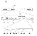
- FIG. 1shows the hierarchy of the seven-layered OSI standard.
- the OSI standard 100includes a physical layer 110 , a data link layer 120 , a network layer 130 , a transport layer 140 , a session layer 150 , a presentation layer 160 , and an application layer 170 .
- the physical (PHY) layer 110conveys the bit stream through the network at the electrical, mechanical, functional, and procedural level. It provides the hardware means of sending and receiving data on a carrier.
- the data link layer 120describes the representation of bits on the physical medium and the format of messages on the medium, sending blocks of data (such as frames) with proper synchronization.
- the networking layer 130handles the routing and forwarding of the data to proper destinations, maintaining and terminating connections.
- the transport layer 140manages the end-to-end control and error checking to ensure complete data transfer.
- the session layer 150sets up, coordinates, and terminates conversations, exchanges, and dialogs between the applications at each end.
- the presentation layer 160converts incoming and outgoing data from one presentation format to another.
- the application layer 170is where communication partners are identified, quality of service is identified, user authentication and privacy are considered, and any constraints on data syntax are identified.
- the IEEE 802 Committeehas developed a three-layer architecture for local networks that roughly corresponds to the physical layer 110 and the data link layer 120 of the OSI standard 100 .
- FIG. 2shows the IEEE 802 standard 200 .
- the IEEE 802 standard 200includes a physical (PHY) layer 210 , a media access control (MAC) layer 220 , and a logical link control (LLC) layer 225 .
- the PHY layer 210operates essentially as the PHY Layer 110 in the OSI standard 100 .
- the MAC and LLC layers 220 and 225share the functions of the data link layer 120 in the OSI standard 100 .
- the LLC layer 225places data into frames that can be communicated at the PHY layer 210 ; and the MAC layer 220 manages communication over the data link, sending data frames and receiving acknowledgement (ACK) frames.
- ACKacknowledgement
- FIG. 3is a block diagram of a wireless network 300 that could use the IEEE 802.15 standard 200 .
- the network 300is a wireless personal area network (WPAN), or piconet.
- WPANwireless personal area network
- piconetwireless personal area network
- the present inventionalso applies to other settings where bandwidth is to be shared among several users, such as, for example, wireless local area networks (WLAN), or any other appropriate wireless network.
- WLANwireless local area networks
- piconetrefers to a network of devices connected in an ad hoc fashion, having one device act as a coordinator (i.e., it functions as a server) while the other devices (sometimes called stations) follow the time allocation instructions of the coordinator (i.e., they function as clients).
- the coordinatorcan be a designated device, or simply one of the devices chosen to function as a coordinator.
- One primary difference between the coordinator and non-coordinator devicesis that the coordinator must be able to communicate with all of the devices in the network, while the various non-coordinator devices need not be able to communicate with all of the other non-coordinator devices.
- the network 300includes a coordinator 310 and a plurality of devices 321 – 325 .
- the coordinator 310serves to control the operation of the network 300 .
- the system of coordinator 310 and devices 321 – 325may be called a piconet, in which case the coordinator 310 may be referred to as a piconet coordinator (PNC).
- PNCpiconet coordinator
- Each of the non-coordinator devices 321 – 325must be connected to the coordinator 310 via primary wireless links 330 , and may also be connected to one or more other non-coordinator devices 321 – 325 via secondary wireless links 340 , also called peer-to-peer links.
- FIG. 3shows bi-directional links between devices, the could also be unidirectional.
- each bi-directional link 330 , 340could be shown as two unidirectional links, the first going in one direction and the second going in the opposite direction.
- the coordinator 310may be the same sort of device as any of the non-coordinator devices 321 – 325 , except with the additional functionality for coordinating the system, and the requirement that it communicate with every device 321 – 325 in the network 300 .
- the coordinator 310may be a separate designated control unit that does not function as one of the devices 321 – 325 .
- the coordinator 310will be considered to be a device just like the non-coordinator devices 321 – 325 .
- alternate embodimentscould use a dedicated coordinator 310 .
- individual non-coordinator devices 321 – 325could include the functional elements of a coordinator 310 , but not use them, functioning as non-coordinator devices. This could be the case where any device is a potential coordinator 310 , but only one actually serves that function in a given network.
- Each device of the network 300may be a different wireless device, for example, a digital still camera, a digital video camera, a personal data assistant (PDA), a digital music player, or other personal wireless device.
- a digital still camerafor example, a digital still camera, a digital video camera, a personal data assistant (PDA), a digital music player, or other personal wireless device.
- PDApersonal data assistant
- the various non-coordinator devices 321 – 325are confined to a usable physical area 350 , which is set based on the extent to which the coordinator 310 can successfully communicate with each of the non-coordinator devices 321 – 325 . Any non-coordinator device 321 – 325 that is able to communicate with the coordinator 310 (and vice versa) is within the usable area 350 of the network 300 . As noted, however, it is not necessary for every non-coordinator device 321 – 325 in the network 300 to communicate with every other non-coordinator device 321 – 325 .
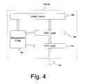
- FIG. 4is a block diagram of a device 310 , 321 – 325 from the network 300 of FIG. 3 .
- each devicei.e., each coordinator 310 or non-coordinator device 321 – 325
- PHYphysical
- MACmedia access control
- FIG. 4is a block diagram of a device 310 , 321 – 325 from the network 300 of FIG. 3 .
- each devicei.e., each coordinator 310 or non-coordinator device 321 – 325
- PHYphysical
- MACmedia access control
- the PHY layer 410communicates with the rest of the network 300 via a primary or secondary wireless link 330 or 340 . It generates and receives data in a transmittable data format and converts it to and from a format usable through the MAC layer 420 .
- the MAC layer 420serves as an interface between the data formats required by the PHY layer 410 and those required by the upper layers 430 .
- the upper layers 205include the functionality of the device 310 , 321 – 325 . These upper layers 430 may include TCP/IP, TCP, UDP, RTP, IP, LLC, or the like.
- the coordinator 310 and the non-coordinator devices 321 – 325 in a WPANshare the same bandwidth. Accordingly, the coordinator 310 coordinates the sharing of that bandwidth.
- Standardshave been developed to establish protocols for sharing bandwidth in a wireless personal area network (WPAN) setting.
- the IEEE standard 802.15.3provides a specification for the PHY layer 410 and the MAC layer 420 in such a setting where bandwidth is shared using time division multiple access (TDMA).
- TDMAtime division multiple access
- the MAC layer 420defines frames and superframes through which the sharing of the bandwidth by the devices 310 , 321 – 325 is managed by the coordinator 310 and/or the non-coordinator devices 321 – 325 .
- An object of the present inventionis to provide a method for increasing the data throughput speed for a wireless network.
- Another object of the present inventionis to reduce the amount of dead time in a data transmission scheme by allowing transmitting devices a greater choice of devices that they can send signals to.
- This methodcomprises receiving a channel time allocation assignment at the source device, the channel time allocation assignment indicating: an assigned channel time allocation, a source address indicating that the source device is assigned to transmit during the assigned channel time allocation, and a destination address indicating that a destination device is assigned to listen during the assigned channel time allocation; performing a first determining step to determine whether the source device has primary data to send to the destination device; sending primary data from the source device to the destination device during the assigned channel time allocation if the first determining step determines that the source device does have primary data to send; performing a second determining step to determine whether any time remains in the assigned channel time allocation after the step of sending primary data; performing a third determining step to determine whether the source device has secondary data to send to a secondary device not assigned as the destination device if the second determining step determines that time remains in the assigned channel time allocation; performing a fourth determining step to determine whether the secondary device is listening during the assigned
- the methodmay further comprise: performing a fifth determining step to determine whether any time remains in the assigned channel time allocation after the step of sending secondary data; and repeating the second, third, and fourth determining steps as well as the step of sending secondary data if the fifth determining step determines that time remains in the assigned channel time allocation.
- the source devicemay maintain a device listening mode list of all network devices, the device listening mode list indicating a listening mode that each network device is currently operating in.
- the third determining stepmay be performed by having the source device look up the secondary device in the device listening mode list.
- the listening modesinclude: a listen-to-all mode indicating a policy of listening to all possible channel time allocations regardless of their assigned destination address; a listen-to-multicast mode indicating a policy of listening to all possible channel time allocations that are assigned to a multicast address as the destination address; and a listen-to-source mode indicating a policy of listening to all possible channel time allocations that are assigned to a set unicast address as the destination address.
- Another methodis also provided of transmitting data packets from a source device in a wireless network.
- This methodcomprises: receiving a channel time allocation assignment at the source device, the channel time allocation assignment indicating: an assigned channel time allocation, a source address indicating that the source device is assigned to transmit during the assigned channel time allocation, and a destination address indicating that a destination device is assigned to listen during the assigned channel time allocation; performing a first determining step to determine whether the source device has secondary data to send to a secondary device not assigned as the destination device; performing a second determining step to determine whether the secondary device is listening during the assigned channel time allocation if the first determining step determines that the first device has secondary data to send to the secondary device; and sending secondary data from the source device to the secondary device during the assigned channel time allocation if the second determining step determines that the source device does have secondary data to send.
- the methodmay further comprise: performing a third determining step to determine whether any time remains in the assigned channel time allocation after the step of sending secondary data; and repeating the first, second, and third determining steps as well as the step of sending secondary data if the third determining step determines that time remains in the assigned channel time allocation.
- the source devicemay maintain a device listening mode list of all network devices, the device listening mode list indicating a listening mode that each network device is currently operating in.
- the third determining stepmay be performed by having the source device look up the secondary device in the device listening mode list.
- the listening modesinclude: a listen-to-all mode indicating a policy of listening to all possible channel time allocations regardless of their assigned destination address; a listen-to-multicast mode indicating a policy of listening to all possible channel time allocations that are assigned to a multicast address as the destination address; and a listen-to-source mode indicating a policy of listening to all possible channel time allocations that are assigned to a set unicast address as the destination address.
- Still another methodis provided of transmitting data packets from a source device in a wireless network.
- This methodcomprises: receiving a channel time allocation assignment at the source device, the channel time allocation assignment indicating: an assigned channel time allocation, a source address indicating that the source device is assigned to transmit during the assigned channel time allocation, and a destination address indicating that a destination device is assigned to listen during the assigned channel time allocation; performing a first determining step to determine whether the source device has primary data to send to the destination device; sending primary data from the source device to the destination device during the assigned channel time allocation if the first determining step determines that the source device does have primary data to send; performing a second determining step to determine whether any time remains in the assigned channel time allocation after the step of sending primary data; performing a third determining step to determine which non-destination devices are listening during the assigned channel time allocation if the second determining step determines that time remains in the assigned channel time allocation; performing a fourth determining step to determine whether the source device has secondary data to send to a secondary device if the third
- the methodmay further comprise: performing a fifth determining step to determine whether any time remains in the assigned channel time allocation after the step of sending secondary data; and repeating the second, third, and fourth determining steps as well as the step of sending secondary data if the fifth determining step determines that time remains in the assigned channel time allocation.
- the source devicemay maintain a device listening mode list of all network devices, the device listening mode list indicating a listening mode that each network device is currently operating in.
- the third determining stepmay be performed by having the source device look up the secondary device in the device listening mode list.
- the listening modesinclude: a listen-to-all mode indicating a policy of listening to all possible channel time allocations regardless of their assigned destination address; a listen-to-multicast mode indicating a policy of listening to all possible channel time allocations that are assigned to a multicast address as the destination address; and a listen-to-source mode indicating a policy of listening to all possible channel time allocations that are assigned to a set unicast address as the destination address.
- FIG. 1is a block diagram of the OSI standard for a computer communication architecture
- FIG. 2is a block diagram of the IEEE 802 standard for a computer communication architecture
- FIG. 3is a block diagram of a wireless network
- FIG. 4is a block diagram of a device or coordinator in the wireless network of FIG. 3 ;
- FIG. 5is a block diagram of a superframe according to preferred embodiments of the present invention.
- FIG. 6is a block diagram of a frame according to a preferred embodiment of the present invention.
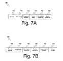
- FIGS. 7A and 7Bare block diagrams showing the MAC header of FIG. 6 according to preferred embodiments of the present invention.
- FIGS. 8A through 8Gare block diagrams showing exemplary payloads from FIG. 6 according to a first preferred embodiment of the present invention.
- FIG. 9is a block diagram showing an arrangement of elements in a superframe in accordance with the first preferred embodiment of the invention.
- FIG. 10is a block diagram showing an arrangement of elements in a superframe in accordance with the second preferred embodiment of the invention.
- FIG. 11is a flow chart showing a data stream control process according to a preferred embodiment of the present invention.
- the present inventionprovides a method of coordinating devices 310 , 321 – 325 either operating in a network 300 or trying to join a network 300 through the use of cyclic beacons inside superframes that define the data path across the network 300 .
- One important aspect of coordinating devices 310 , 321 – 325 in a network 300is uniquely identifying each of the devices 310 , 321 – 325 . There are several ways in which this can be accomplished.
- each device 310 , 321 – 325has a unique MAC address that can be used to identify it,. This MAC address is generally assigned by the manufacturer so that no two devices 310 , 321 – 325 have the same MAC address.
- One set of standards that is used in preferred embodiments of the present invention to govern MAC addressescan be found in IEEE Std. 802-1990, “IEEE Standards for Local and Metropolitan Area Networks: Overview and Architecture.”
- the network 300can also assign a device ID to each device 310 , 321 – 325 in the network 300 to use in addition its unique MAC address.
- the MAC 420uses ad hoc device IDs to identify devices 310 , 321 – 325 . These device IDs can be used, for example, in the MAC header.
- the device IDsare generally much smaller than the MAC addresses for each device 310 , 321 – 325 .
- the device IDsare 4-bits and the MAC addresses are 48-bits.
- Each device 310 , 321 – 325should maintain mapping table that maps the correspondence between device IDs and MAC addresses.
- the tableis filled in based on the device ID and MAC address information provided to the devices 321 – 325 by the coordinator 310 . This allows each device 310 , 321 – 325 to reference themselves and the other devices in the network 300 by either device ID or MAC address.
- the networkcan use a unicast address to identify a single device 310 , 321 – 325 , a multicast address to identify multiple devices 310 , 321 – 325 , and a broadcast address to identify all of the devices 310 , 321 – 325 .
- the network 300uses unicast addresses to identify a single device 310 , 321 – 325 .
- the device IDsare used as unicast addresses. Since each device 310 , 321 – 325 will have a unique device ID, they will also each have a unique unicast address. Unicast addresses can be used to identify both the source and destination for a frame or data stream.
- the network 300uses a multicast address to refer to a plurality of devices 310 , 321 – 325 .
- Thisis preferably a single address that is the same length and format as the device IDs, but is unassigned to any single device 310 , 321 – 325 .
- the multicast addresswill only used when referring to the destination for a frame or data stream since only a single device 310 , 321 – 325 can operate as a transmitter at given time.
- the multicast addressWhen the multicast address is used, it will preferably also have an associated set of stream information that indicates which specific subset of devices 310 , 321 – 325 is encompassed by the current multicast.
- each multicast addresscould be directed to a specific multicast group of devices 310 , 321 – 325 , and may also have an associated set of stream information that indicates which specific subset of devices 310 , 321 – 325 is encompassed by the multicast address.
- the network 300uses a broadcast address to refer to all of the devices 310 , 321 – 325 in the network. This is preferably a single address that is the same length and format as the device IDs, but is unassigned to either any single device 310 , 321 – 325 or as a multicast address.
- the broadcast addresswill only used when referring to the destination for a frame or data stream since only a single device 310 , 321 – 325 can operate as a transmitter at given time.
- the available bandwidth in a given network 300is split up in time by the coordinator 310 into a series of repeated superframes. These superframes define how the available transmission time is split up among various tasks. Individual frames of data are then transferred within these superframes in accordance with the timing set forth in the superframe.
- FIG. 5is a block diagram of a superframe according to preferred embodiments of the present invention.
- each superframe 500may include a beacon period 510 , a contention access period (CAP) 520 , and a contention free period (CFP) 530 .
- CAPcontention access period
- CCPcontention free period
- the beacon period 510is set aside for the coordinator 310 to send a beacon frame (see, e.g., FIGS. 6 and 8H ) out to the non-coordinator devices 321 – 325 in the network 300 .
- Each device 321 – 325knows how to recognize a beacon 510 prior to joining the network 300 , and uses the beacon 510 both to identify an existing network 300 and to coordinate communication within the network 300 .
- the CAP 520may be used to transmit commands or asynchronous data across the network.
- the CAP 520may be eliminated in many embodiments and the system would then pass commands solely during the CFP 530 .
- the CFP 530includes a plurality of time slots 540 .
- These time slots 540are assigned by the coordinator 310 to pairs of devices 310 , 321 – 325 for transmission of information between them (i.e., each time slot 540 is assigned to a specific transmitter-receiver pair—also called a source-destination pair).
- each time slot 540is assigned to a specific transmitter-receiver pair—also called a source-destination pair).
- the term “pair”is used, this may actually encompass more than one device 310 , 321 – 325 , since the receiver/destination may be all the devices in the network 300 (i.e., a broadcast destination) or a group of devices in the network 300 (i.e., a multicast destination).
- the time slots 540may be management time slots (MTSs) or guaranteed time slots (GTSs).
- An MTSis a time slot that is used for transmitting administrative information between the coordinator 310 and one of the non-coordinator devices 321 – 325 . As such it must have the coordinator 310 be one member of the transmission pair.
- An MTSmay be further defined as an uplink MTS (UMTS) if the coordinator 310 is the receiving device, or a downlink MTS (DMTS) if the coordinator 310 is the transmitting device.
- UMTSuplink MTS
- DMTSdownlink MTS
- short frames of asynchronous datamay be sent during management time slots.
- CTAschannel time allocations
- GTSscan be called guaranteed channel time allocations (GCTAs) and MTSs can be called management channel time allocations (MCTAs).
- GCTAsguaranteed channel time allocations
- MTSsmanagement channel time allocations
- a GTSis a time slot that is used for transmitting non-administrative data between devices 310 , 321 – 325 in the network 300 . This can include data transmitted between two non-coordinator devices 321 – 325 , or non-administrative data transmitted between the coordinator 310 and a non-coordinator device 321 – 325 .
- a streamis a communication between a source device and one or more destination devices.
- the source and destination devicescan be any devices 310 , 321 – 325 in the network 300 .
- the destination devicescan be all or some of the devices 310 , 321 – 325 in the network 300 .
- the source addressmust be a unicast address (i.e., a single device ID), but the destination address can be a unicast address, the multicast address, or the broadcast address.
- the uplink MTSmay be positioned at the front of the CFP 530 and the downlink MTSs positioned at the end of the CFP 530 to give the coordinator 310 a chance to respond to an uplink MTS in the in the downlink MTS of the same superframe 500 .
- the coordinator 310may instead respond in another downlink MTS assigned to that non-coordinator device 321 – 325 in a later superframe 500 .
- the superframe 500is a fixed time construct that is repeated in time.
- the specific duration of the superframe 500is described in the beacon 510 .
- the beacon 510generally includes information regarding how often the beacon 510 is repeated, which effectively corresponds to the duration of the superframe 500 .
- the beacon 510also contains information regarding the network 300 , such as the identity of the transmitter and receiver of each time slot 540 , and the identity of the coordinator 310 .
- the system clock for the network 300is preferably synchronized through the generation and reception of the beacons 510 .
- Each non-coordinator device 321 – 325will store a synchronization point time upon successful reception of a valid beacon 510 , and will then use this synchronization point time to adjust its own timing.
- guard timesare interspersed between time slots 540 in a CFP 530 .
- Guard timesare used in TDMA systems to prevent two transmissions from overlapping in time because of inevitable errors in clock accuracies and differences in propagation times based on spatial positions.
- the propagation timewill generally be insignificant compared to the clock accuracy.
- the amount of guard time requiredis preferably based primarily on the clock accuracy and the duration since the previous synchronization event.
- Such a synchronizing eventwill generally occur when a device 321 – 325 successfully receives a beacon frame from the coordinator 310 .
- guard timemay be used for the entire superframe.
- the guard timewill preferably be placed at the end of each beacon frame, GTS, and MTS.
- each superframe 500information is passed between devices 310 , 321 – 325 through frames, which define how signals will be sent.
- a framedefines how the bits that make up the signal are organized so that they will be sent in a recognizable format.
- FIG. 6is a block diagram of a frame according to preferred embodiments of the present invention.
- the frame 600may include a preamble 610 , a header 620 , a header check sequence (HCS) 630 , a payload 640 , a frame check sequence (FCS) 450 , and a postamble 660 .
- the header 620is preferably divided into a physical header 622 and a MAC header 624 . These elements will be discussed in more detail below.
- the header 620is divided into a physical header 622 and a MAC header 624 .
- the physical header 622provides information about the physical signal sent between devices 310 , 321 – 325 , and it preferably includes at least the length of the current payload 640 . It may also include information relating to the data rate at which the payload 640 is sent, or other information.
- the MAC header 624preferably includes data relating to the transfer of frames between devices 310 , 321 – 325 .
- FIGS. 7A and 7Bare block diagrams showing the MAC header of FIG. 6 according to preferred embodiments of the present invention.
- FIG. 7Ais a block diagram showing the MAC header according to a first preferred embodiment
- FIG. 7Bis a block diagram showing the MAC header according to a second preferred embodiment.
- the MAC header 624may include a version indicator 705 , an ACK policy indicator 710 , a sequence number 715 , a frame type 720 , a destination device ID 725 , and a source device ID 730 .
- a beacon frame typeindicates that the frame is a beacon 510 , which is generated by the coordinator 310 at start of every superframe 500 .
- a status request frameis sent by the coordinator 310 in an MTS to check on the status of the destination device.
- An association request frameis sent by a new device requesting that the coordinator 310 let it join the network 310 .
- An association reply frameis sent by the coordinator 310 to a new device in response to an association request frame.
- a disassociation indication frameis sent by a current device 321 – 325 to the coordinator 310 to indicate disassociation from the network 300 .
- An ACK frameindicates an immediate acknowledgement (ACK) of a previous frame.
- a data frameis sent between any two devices to pass isochronous data along a stream.
- a stream allocation request frameis sent by a current device 321 – 325 to the coordinator 310 to request that it be allocated a stream.
- a stream allocation reply frameis sent from the coordinator 310 to a current device 321 – 325 in response to a stream request frame.
- a stream de-allocation frameis sent from a current device 321 – 325 to the coordinator 310 to indicate that the current device 321 – 325 no longer needs a stream.
- a stream reallocation frameis sent from a device 321 – 325 to a coordinator 310 to request a change of an already-allocated stream.
- the destination device ID 725is the ID of the device or devices 310 , 321 – 325 to which the frame 600 is being sent. If the frame 600 is being sent to a single device 310 , 321 – 325 then the destination device ID is simply the device ID of the destination device 310 , 321 – 325 (i.e., its unicast address). If the frame 600 is being sent to all of the devices 310 , 321 – 325 in the network 300 , then the destination device ID is a broadcast ID (i.e., the broadcast address). If the frame 600 is being sent to some subset of devices 310 , 321 – 325 then the destination device ID is a multicast ID (i.e., the multicast address).
- the source device ID 730is the device ID (i.e., the unicast address) of the device 310 , 321 – 325 from which the frame 600 is being sent.
- FIG. 7Bshows a MAC header 624 according to a second preferred embodiment of the present invention.
- This embodimentconforms with the header format in the IEEE 802.15.3 standard.
- the MAC header 624may include a frame control 755 , a network ID 760 , a destination device ID 725 , a source device ID 730 , a fragmentation control 765 , and a stream control 770 .
- the destination device ID 725is the ID of the device or devices 310 , 321 – 325 to which the frame 600 is being sent. If the frame 600 is being sent to a single device 310 , 321 – 325 then the destination device ID is simply the device ID of the destination device 310 , 321 – 325 (i.e., its unicast address). If the frame 600 is being sent to all of the devices 310 , 321 – 325 in the network 300 , then the destination device ID is a broadcast ID (i.e., the broadcast address). If the frame 600 is being sent to some subset of devices 310 , 321 – 325 then the destination device ID is a multicast ID (i.e., the multicast address).
- the source device ID 730is the device ID (i.e., the unicast address) of the device 310 , 321 – 325 from which the frame 600 is being sent.
- the stream control 770indicates a unique stream identifier for the stream used by the current frame 600 .
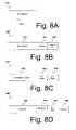
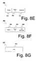
- FIGS. 8A through 8Hare block diagrams showing exemplary payloads 640 from FIG. 6 according to a first preferred embodiment of the present invention.
- FIG. 8Ais an association request payload
- FIG. 8Bis an association reply payload
- FIG. 8Cis a stream request payload
- FIG. 8Dis a stream reply payload
- FIG. 8Eis a stream free payload
- FIG. 8Fis a stream reallocation payload
- FIG. 8Gis a data payload
- FIG. 8His a beacon payload.
- FIG. 8Ais a block diagram of shows an association request payload according to a preferred embodiment. This is used when a MAC 420 in a new device requests to become a member of the network 300 . As shown in FIG. 8A , the association request payload 810 may include the MAC address of the requestor 812 .
- FIG. 8Bis a block diagram of an association reply payload according to a preferred embodiment. This is used when the coordinator 310 responds to an association request frame 820 . As shown in FIG. 8B , the association reply payload 820 may include a MAC address 822 , a padding block 824 , and a device ID 826 .
- FIG. 8Cis a block diagram of a stream request payload according to the first preferred embodiment. This is used when a device 321 – 325 requests a stream to communicate with another device. As shown in FIG. 8C , the stream request payload 830 may include a destination device ID 832 , a GTS lower value 834 , a GTS upper value 836 , and a reserved block 838 .
- the destination device ID 832is the device ID of the receiver of the packets in the current data stream.
- the destination address 832may be any unicast address or the broadcast address, or a multicast address.
- the GTS lower value 834is the minimum acceptable amount of GTSs that can be allocated to the data to be sent.
- the GTS upper value 836is the maximum requested GTSs for the data transfer.
- the GTS lower value 834 and the GTS upper value 836are preferably indicative of the number of time units (e.g. in microseconds) for the request.
- the GTS lower value 834should be less than or equal to the GTS upper value 836 .
- the reserved block 838represents bits in the payload 640 that are not used in this embodiment. In alternate embodiments other parameters may be altered to reduce or eliminate the reserved block 838 .
- FIG. 8Dis a block diagram of a stream reply payload according to the first preferred embodiment. This is used when the coordinator 310 responds to a stream request payload 830 from a device 321 – 325 .
- the stream reply payload 840may include a stream ID 842 , a destination ID 844 , a GTS slot value 846 , and a reserved block 848 .
- the stream-ID 842is the unique identifier given to the stream assigned to the requesting device 321 – 325 . This value is set at a specified Stream Failure value if the allocation failed (e.g., coded as 0 ⁇ F in the first preferred embodiment).
- the destination ID 844is the device ID of the designated receiver device. This can be a unicast address, a broadcast address, or a multicast address.
- the GTS slot value 846indicates the number of assigned time units.
- the reserved block 838represents bits in the payload 640 that are not used in this embodiment. In alternate embodiments other parameters may be altered to reduce or eliminate the reserved block 838 .
- FIG. 8Eis a block diagram of a stream free payload according to the first preferred embodiment. This us used by a device, 321 – 325 to inform the coordinator 310 that it no longer intends to use a stream and that the corresponding GTS may be reused. As shown in FIG. 8E , the stream free payload 850 may include a padding block 852 , a stream ID 854 , and a reserved block 856 .
- the padding block 852is a set of bits that are unused but allocated to the stream free payload 850 . This is because the frames are preferably aligned to octets and the padding block 852 is needed to provide correct alignment. In alternate embodiments where no octet alignment is used or where there is no need to pad to maintain octet alignment, the padding block could be eliminated. Preferably the value stored in the padding block 852 is zero, i.e., it is a string of zeros.
- the stream ID 854is the same stream ID 842 as was returned in an associated stream reply payload 840 . It provides a unique identifier for the assigned stream.
- the reserved block 856represents bits in the payload 640 that are not used in this embodiment. In alternate embodiments other parameters may be altered to reduce or eliminate the reserved block 856 .
- FIG. 8Fis a block diagram of a stream reallocation payload according to the first preferred embodiment. This is used by a device to request an increased or decreased amount of GTSs for a stream. In alternate embodiments this may also be used to request changes in other parameters. As shown in FIG. 8F , the stream reallocation payload 860 may include a padding block 862 , a stream ID 864 , and a GTS requested value 866 .
- the padding block 862is a set of bits that are unused but allocated to the stream reallocation payload 860 . This is because the frames are preferably aligned to octets and the padding block 862 is needed to provide correct alignment. In alternate embodiments where no octet alignment is used or where there is no need to pad to maintain octet alignment, the padding block could be eliminated. Preferably the value stored in the padding block 862 is zero, i.e., it is a string of zeros.
- the stream ID 864is the same stream ID 842 as was returned in an associated stream reply payload 840 . It provides a unique identifier for the assigned stream.
- the GTS requested value 866is the new desired amount of GTSs that the requestor wants.
- the coordinator 310may deny the request and leave the GTS assignment unchanged, or it may allow the request and raise or lower the GTS assignment accordingly, or it may partially allow the request, raising or lowering the GTS assignment less than the amount requested.
- FIG. 8Gis a block diagram of a data payload according to the first preferred embodiment. This is used when data must be sent between two devices 310 , 321 – 325 .
- the data payload 870may include a data block 872 .
- This data block 872is simply a string of data bits of a length set forth in the physical header 622 .
- the frame 600may also include a postamble 660 , which is a bit sequence set at the end of each frame 600 to assist in synchronization or perform other administrative functions such as flush on tail bits or symbols.
- a postamble 660can be eliminated in some embodiments. In fact, the preferred embodiment described with respect to FIG. 7A below does not use a postamble 660 .
- FIGS. 9 and 10show two preferred embodiments of a specific superframe design.
- FIG. 9is a block diagram showing an arrangement of elements in a superframe in accordance with the first preferred embodiment of the invention.
- FIG. 10is a block diagram showing an arrangement of elements in a superframe in accordance with the second preferred embodiment of the invention.
- the transmission scheme 900involves dividing the available transmission time into a plurality of superframes 910 .
- This embodimentuses the MAC header 622 disclosed in FIG. 7A and the payloads 640 disclosed in FIGS. 8A through 8H .
- each individual superframe 910includes a beacon frame 920 , an uplink MTS 930 , a plurality of GTSs 940 , and a downlink MTS 950 .
- the beacon frame 920is a frame 600 whose payload 640 is a beacon payload 880 , as shown in FIG. 8H . It indicates by association ID (known as a device ID in the IEEE 802.15.3 draft standard) a device 321 – 325 that is assigned to the current superframe 910 . It also indicates via the RxTx table 888 [FIX THIS?] the transmitter/receiver pairs that are assigned to the individual GTSs 940 .
- a stream indexmay be added to allow multiple streaming between the same source-destination pair. This can be shown, for example, in the CTA for the draft 802.15.3 standard, which allows for such multiple streaming.
- the uplink MTS 930is set aside for the device 321 – 325 assigned (e.g., by device ID in an MTS information element) to the current superframe 910 to upload signals to the coordinator 310 . All other devices 321 – 325 remain silent on the current channel during this time slot. In alternate embodiments that use multiple channels, all other stations on that channel must remain silent during an uplink MTS 930 , though they may still transmit on alternate channels.
- the plurality of GTSs 940are the time slots set aside for each of the devices 310 , 321 – 325 to communicate with each other. They do so in accordance with the information set forth in the CTA IES 888 [CHECK THIS WITH BILL] in the beacon 920 .
- Each GTS 940is preferably large enough to transmit one or more data frames. When a device pair is assigned multiple GTSs 940 , they are preferably contiguous.
- the downlink MTS 950is set aside for the coordinator 310 to download signals to the device 321 – 325 assigned to the current superframe 910 . All other devices 321 – 325 may ignore all transmissions during this time slot.
- the length of the superframe 910is fixed, and is preferably chosen to have a duration between 10 and 30 ms in order to minimize the data buffering requirements.
- the lengths of the uplink and downlink MTSs 930 and 950must be chosen to handle the largest possible management frame, an immediate ACK frame, and the receiver-transmitter turnaround time.
- the length and numberis flexible.
- the transmission scheme 1000involves dividing the available transmission time into a plurality of superframes 1010 .
- This embodimentuses the MAC header 624 disclosed in FIG. 7B .
- the payloads 640 usedare preferably those used in the IEEE 802.15.3 standard.
- the data transmission scheme 1000includes transmitting successive superframes 1010 in time across the network 300 .
- Each superframe 1010includes a beacon 1020 , an optional contention access period (CAP) 1030 , and a contention free period (CFP) 1040 .
- the contention free period 1040may include one or more management time slots (MTSs) 1050 and one or more guaranteed time slots (GTSs) 1060 .
- MTSsmanagement time slots
- GTSsguaranteed time slots
- Management time slots 1050can be downlink management time slots (DMTSs) in which information is sent from the coordinator 310 to a non-coordinator device 321 – 325 , or uplink management time slots (UMTSs) in which information is sent from a non-coordinator device 321 – 325 to the coordinator 310 .
- DMTSsdownlink management time slots
- UMTSsuplink management time slots
- MTSscan also be shared among multiple devices 321 – 325 . In this case a convention resolution method, such as slotted Aloha, must be used. In addition, if a CAP 1030 is used to pass administrative information, the use of MTSs 1050 may be reduced or eliminated.
- the coordinator 310will designate how the devices 310 , 321 – 325 should use the available guaranteed time slots 1060 .
- the guaranteed time slots 1060 in this embodimentare preferably dynamic in size. Each transmitter-receiver pair that is allocated a GTS 1060 is also told the duration of the GTS 1060 that the pair is assigned to the beacon. These durations may be of different sizes for different GTSs within a single superframe 1010 . Furthermore, the length and position of a given GTS 1060 may change across different superframes 1010 , limited only by the ability of the coordinator 310 to successfully inform the non-coordinator devices 321 – 325 of the change. The starting times and durations of the guaranteed time slots 1060 are determined by the coordinator 310 and sent to the devices 321 – 325 during the contention access period 1030 or one of the management time slots 1050 , as implemented.
- the coordinator 310uses the beacon 1020 (in whatever format it is) and the MTSs to coordinate the scheduling of the individual devices 310 , 321 – 325 into their respective guaranteed time slots 1060 .
- All devices 310 , 321 – 325listen to the coordinator 310 during the beacon period 1020 .
- Each device 321 – 325will receive zero or more time slots 1050 , 1060 , being notified of each start time and duration from the coordinator 310 during the beacon period 1020 .
- the coordinator 310automatically allocates management time slots 1050 to each device 321 – 325 . However, guaranteed time slots 1060 are only assigned when the device 321 – 325 requests them.
- Channel time allocation (CTA) fields in the beacon 1020include start times, packet duration, source device ID, destination device ID, and a stream index.
- This beacon informationuses what is often called TLV format, which stands for type, length, and value.
- TLV formatstands for type, length, and value.
- the coordinator 310sends the beacon 1020 to all of the non-coordinator devices 321 – 325 at the beginning of each superframe 1010 .
- the beacon 1020tells each non-coordinator device 321 – 325 the duration or superframe 1010 as well as other information about its MAC address.
- Each beacon 1020will also contain information that is not precisely a CTA.
- One piece of informationwill define the beacon period 1020 and describe the start time and the duration for the beacon period 1020 .
- Anotherwill define the contention access period 1030 (if any) and describe the start time and the duration for the contention access period 1030 .
- Each beaconcan also have multiple CTAs. There will be a CTA for each of the time slot 1050 , 1060 (whether MTS or GTS). Using dynamic time slots, the slot assignments can change the CTAs every superframe.
- each device 310 , 321 – 325must hear the beacon 1020 so that it will know what time slots 1050 , 1060 have been assigned to it as either a transmitter or receiver. If the device misses the beacon 1020 , it may listen to the entire superframe 1010 just in case it is receiving data. Furthermore, in some implementations it may not be allowed to transmit for the duration of the superframe 1010 because it does not know when it is permitted to transmit. This is detrimental to the system because it may lead to interruptions in data transmission.
- the networkcan pass control and administrative information between the coordinator 310 and the various devices 321 – 325 through the optional contention access period 1030 , the management time slots 1050 , or both. For example, this can involve information about new devices that want to join the network 300 .
- the particular implementationwill determine what particular option is used: it could include a contention access period 1030 , one or more management time slots 1050 , or some combination of both.
- Individual devices 310 , 321 – 325transmit frames during the contention free period 1040 according to the schedule set forth in the beacon 1020 .
- the pair of devices 310 , 321 – 325 assigned to a given guaranteed time slots 1060use that GTS 1060 assigned to them to transmit frames 1070 between each other. These may be data frames from the designated transmitter to the designated receiver, or acknowledgement (ACK) frames from the designated receiver to the designated transmitter.
- ACKacknowledgement
- guard times 1080are preferably provided between frames to account for errors in clock accuracies and differences in propagation delays based on spatial positions of the devices 310 , 321 – 325 .
- One problem in an ad hoc network 300is coordinating the entry and departure of devices into and out of the network 300 , and coordinating the passage of administrative frames between the coordinator 310 and the devices 321 – 325 .
- the present inventionaddresses this problem by using cyclic beacons to monitor the network 300 and the devices 310 , 321 – 325 in it.
- Each networkpreferably has a set number N of allowable devices 310 , 321 – 325 .
- CTAschannel time allocations
- GTSschannel time allocations
- the CTA assigned to a source-destination pair for a given set of transmissionsis based on an estimate of the CTA required for that source-destination pair. However, it may turn out that for any specific CTA, transmissions between a source-destination pair are either backed up or remain unused or underused.
- One way to alleviate this problemis to make use of the unused or underused CTAs to pass data that has overflowed its assigned CTA. This can reduce the number of data logjams and increase the system's transmission rate by allowing the use of some unused channel time to send waiting data packets.
- the assigned transmitting (source) deviceIn operation this is accomplished by allowing the assigned transmitting (source) device to send data to any receiving (destination) device that it knows will be listening during a given CTA, regardless of whether that receiving device was specifically assigned as the destination for that CTA.
- the assigned source deviceis preferably the only device that can transmit during the allocated channel time. This will prevent collisions from occurring by making certain that no two devices 310 , 321 – 325 will try and transmit at the same time.
- the source devicewill preferably be identified when the CTA is assigned by a source device ID (i.e., a unicast address) that corresponds to the device ID for one of the devices 310 , 321 – 325 in the network 300 .
- the source devicecan determine which devices 310 , 321 – 325 are listening during a given CTA by considering two sets of devices: those that must listen to the CTA, and those that voluntarily listen during the CTA.
- One reason that some devices 310 , 321 – 325 will not be listeningis that they will periodically enter sleep modes to conserve power when they are not required to listen.
- the set of devices 310 , 321 – 325 that must listen to the CTAis simple to determine. It includes that device or devices 310 , 321 – 325 that are assigned as the destination device for that CTA, as indicated by the destination device ID when the CTA is assigned. As noted above, this destination device ID can be a unicast address, a multicast address, or a broadcast address. The particular address used will tell the devices in the system who must listen to that CTA. In other words, if a unicast address is used, the device 310 , 321 – 325 belonging to that unicast address must listen during that unicast CTA.
- all devices 310 , 321 – 325 associated with that particular multicastmust listen during that multicast CTA.
- all devices 310 , 321 – 325 in the network 300must listen during that broadcast CTA.
- the set of devices 310 , 321 – 325 that may listen to the CTAdepends entirely on the individual devices 310 , 321 – 325 , since each may elect to listen to more CTAs than are strictly necessary. For example, some devices may listen to all multicast CTAs. Other devices might listen to all transmissions from a particular device (e.g., a transmitting device that the current device is receiving data from in a different part of the superframe 500 ). Still other devices 310 , 321 – 325 may listen to all CTAs. And, of course, some devices 310 , 321 – 325 may listen to only the CTAs that they are specifically required to. Generally this is an issue of power consumption.
- Devices 310 , 321 – 325 that are less constrained by powercan listen to more CTAs than devices 310 , 321 – 325 that must conserve their power supply.
- Each devicewill preferably identify its receiving mode (i.e., which extra CTAs it will listen to) when it joins the network.
- any given CTAthere will be a single source device authorized to transmit, one or more destination devices that are assigned to listen, and possible one or more devices that elect to listen.
- the source devicewill transmit frames to the assigned destination device or devices. However, as noted above, sometimes it will have nothing it needs to transmit to the assigned destination device(s). But it may well have something it needs to transmit to a secondary destination device (i.e., one not assigned as a destination in the current CTA). And if that secondary destination device is listening during the current CTA, the source device can start a unicast stream to send information to the secondary destination device.
- a secondary destination devicei.e., one not assigned as a destination in the current CTA.
- the source devicecan start a unicast stream to send information to the secondary destination device.
- the source devicesends frames to the assigned destination during the current CTA, but finishes transmitting before the end of the CTA. In that case if the source device has something that it needs to send to a listening secondary destination device that will fit in the remaining part of the CTA, then the source device can start a new unicast stream to send information to the secondary destination device.
- each deviceneed only determine which devices are listening during a given channel time allocation to determine who is available as a recipient for these secondary data streams.
- This informationis preferably maintained at the coordinator 310 , which receives the information from each device 321 – 325 when they first associate with the network 300 .
- the receiving mode for each devicecan be sent in an association request in a device capabilities field.
- a battery-powered deviceIn an effort to maximize both power efficiency and data transmission, a battery-powered device will usually be programmed to not report its capability as listen-to-all (i.e., that it will listen to all CTAs), listen-to-all-source (i.e., that it will listen to all CTAs from a given device), or listen-to-all-multicast (i.e., that it will listen to all multicast CTAs). Therefore, when talking to a battery-powered device, the transmitting device will generally ask for a unicast CTA. However, a device connected to a non-battery power source will more likely report its capability as either listen-to-all, listen-to-all-source, or listen-to-all-multicast.
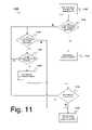
- FIG. 11is a flow chart showing a data stream control process according to a preferred embodiment of the present invention. As shown in FIG. 11 , the process begins when network 300 determines the source-destination pair assigned to a given CTA. (Step 1105 ) this is preferably done by reading the beacon for the superframe.
- the assigned source devicedetermines whether it has anything it needs to send to the assigned destination (keeping in mind that the destination can be a single device or multiple devices). (Step 1110 )
- Step 1115If the assigned source device has data to send to the assigned destination, then it proceeds to do so, taking up as much of the CTA as it needs.
- the assigned source devicedetermines whether it has any data that it needs to send to the assigned destination. (Step 1120 )
- the source devicewaits until the end of the CTA and the network moves onto the next CTA. (Step 1140 )
- each devicewill maintain a list of all potential listening devices and what their listen modes are (i.e., which extra CTAs they will listen to).
- Step 1130If the secondary device is listening, then the assigned source device sends the data to the assigned destination, taking up as much of the CTA as it needs. (Step 1130 )
- the source deviceproceeds back to step 1120 to determine whether it has data that it needs to send to any other secondary destination device.
- the assigned source devicedetermines whether there is any remaining time in the CTA. (Step 1135 )
- step 1120determines whether it has any data it needs to send to any other secondary destination devices. If there is no remaining time, then the assigned source device proceeds to step 1140 and the CTA ends.
- the present inventioncan be used with the IEEE 803.15.3 standard for high-rate WPANs, which is currently under development by the IEEE 802.15 WPANTM Task Group 3 (TG3).
- the details of the current draft 802.15.3 standard, including archives of the 802.15.3 working groupcan be found at: http://www.ieee802.org/15/pub/TG3.html.
- Nothing in this disclosureshould be considered to be incompatible with the draft 802.15.3 standard, as set forth on the IEEE 802 LAN/MAN Standards Committee web page.
- one preferred embodiment of the present inventionis used in an ultrawide bandwidth network. However, it is applicable to other sorts of networks as well.
Landscapes
- Engineering & Computer Science (AREA)
- Computer Networks & Wireless Communication (AREA)
- Signal Processing (AREA)
- Small-Scale Networks (AREA)
- Mobile Radio Communication Systems (AREA)
Abstract
Description
Claims (12)
Priority Applications (1)
| Application Number | Priority Date | Filing Date | Title |
|---|---|---|---|
| US10/680,489US7088702B2 (en) | 2001-10-03 | 2003-10-08 | Method for controlling a data stream in a wireless network |
Applications Claiming Priority (4)
| Application Number | Priority Date | Filing Date | Title |
|---|---|---|---|
| US32642501P | 2001-10-03 | 2001-10-03 | |
| US10/262,946US7280518B2 (en) | 2001-10-03 | 2002-10-03 | Method of operating a media access controller |
| US41652002P | 2002-10-08 | 2002-10-08 | |
| US10/680,489US7088702B2 (en) | 2001-10-03 | 2003-10-08 | Method for controlling a data stream in a wireless network |
Related Parent Applications (1)
| Application Number | Title | Priority Date | Filing Date |
|---|---|---|---|
| US10/262,946Continuation-In-PartUS7280518B2 (en) | 2001-10-03 | 2002-10-03 | Method of operating a media access controller |
Publications (2)
| Publication Number | Publication Date |
|---|---|
| US20040072573A1 US20040072573A1 (en) | 2004-04-15 |
| US7088702B2true US7088702B2 (en) | 2006-08-08 |
Family
ID=32074280
Family Applications (1)
| Application Number | Title | Priority Date | Filing Date |
|---|---|---|---|
| US10/680,489Expired - Fee RelatedUS7088702B2 (en) | 2001-10-03 | 2003-10-08 | Method for controlling a data stream in a wireless network |
Country Status (1)
| Country | Link |
|---|---|
| US (1) | US7088702B2 (en) |
Cited By (29)
| Publication number | Priority date | Publication date | Assignee | Title |
|---|---|---|---|---|
| US20050053043A1 (en)* | 2003-07-17 | 2005-03-10 | Interdigital Technology Corporation | Method and system for delivery of assistance data |
| US20050058062A1 (en)* | 2003-07-17 | 2005-03-17 | Interdigital Technology Corporation | Signaling method for WLAN network control |
| US20050089000A1 (en)* | 2003-10-28 | 2005-04-28 | Samsung Electronics Co., Ltd. | Method for communicating effectively between devices on wireless personal area network |
| US20050204250A1 (en)* | 2004-01-30 | 2005-09-15 | Samsung Electronics Co., Ltd. | Method of retransmitting data frame and network apparatus using the method |
| US20050220070A1 (en)* | 2004-04-02 | 2005-10-06 | Samsung Electronics Co., Ltd. | Apparatus for requesting channel time allocation (CTA) in and method for receiving data during allocated channel time in coordinator-based wireless network |
| US20050243787A1 (en)* | 2004-04-29 | 2005-11-03 | Samsung Electronics Co., Ltd. | Method and apparatus for communication between coordinator-based wireless network and different type of network which are interconnected through a backbone network |
| US20050265372A1 (en)* | 2004-05-25 | 2005-12-01 | Samsung Electronics Co., Ltd. | Method for communication in coordinator-based wireless network and method for communication between coordinator-based wireless networks connected through backbone network |
| US20050286647A1 (en)* | 2004-05-27 | 2005-12-29 | Oki Electric Industry Co., Ltd. | Communication timing control method and apparatus, node, and communication system |
| US20060035589A1 (en)* | 2004-08-16 | 2006-02-16 | Shvodian William M | Method for providing rapid delayed frame acknowledgement in a wireless transceiver |
| US20060050742A1 (en)* | 2004-08-12 | 2006-03-09 | Interdigital Technology Corporation | Method and system for controlling access to a wireless communication medium |
| US20070223527A1 (en)* | 2006-03-24 | 2007-09-27 | Samsung Electronics Co., Ltd. | Method and system for transmission of different types of information in wireless communication |
| US20070286130A1 (en)* | 2006-06-12 | 2007-12-13 | Huai-Rong Shao | System and method for wireless communication of uncompressed video having a link control and bandwidth reservation scheme for control/management message exchanges and asynchronous traffic |
| US20080013519A1 (en)* | 2006-07-14 | 2008-01-17 | Samsung Electronics Co., Ltd. | Method and apparatus for wireless communication in high-frequency band |
| WO2008023957A1 (en)* | 2006-08-25 | 2008-02-28 | Samsung Electronics Co., Ltd. | Method and apparatus for wireless communication |
| WO2008032976A1 (en)* | 2006-09-11 | 2008-03-20 | Samsung Electronics Co., Ltd. | System and method for wireless communication having a device coordinator selection capability |
| US20080259877A1 (en)* | 2004-02-06 | 2008-10-23 | Koninklijke Philips Electronic, N.V. | System and Method for a Dynamic Beacon Period in a Mac Distributed Reservation Protocol |
| US20090147765A1 (en)* | 2004-11-22 | 2009-06-11 | Koninklijke Philips Electronics, N.V. | Air-time fair transmission regulation without explicit traffic specifications for wireless networks |
| US20090323611A1 (en)* | 2008-06-26 | 2009-12-31 | Samsung Electronics Co., Ltd. | System and method for priority driven contention scheme for supporting enhanced QoS in a wireless communication network |
| US20100002639A1 (en)* | 2008-07-02 | 2010-01-07 | Samsung Electronics Co., Ltd. | System and method for reservation of disjoint time intervals in wireless local area networks |
| US20100111050A1 (en)* | 2008-11-05 | 2010-05-06 | Wun Cheol Jeong | Wireless network system using cyclic frame |
| US20110038343A1 (en)* | 2008-03-18 | 2011-02-17 | Ghulam Bhatti | Distributed Beacon Enabled Wireless Networks |
| US7944897B2 (en) | 2005-11-03 | 2011-05-17 | Samsung Electronics Co., Ltd. | Method and system for addressing channel access unfairness in IEEE 802.11n wireless networks |
| US8917743B2 (en) | 2010-10-06 | 2014-12-23 | Samsung Electronics Co., Ltd. | Method and system for enhanced contention avoidance in multi-user multiple-input-multiple-output wireless networks |
| US8953578B2 (en) | 2010-06-23 | 2015-02-10 | Samsung Electronics Co., Ltd. | Method and system for contention avoidance in multi-user multiple-input-multiple-output wireless networks |
| US9232543B2 (en) | 2010-07-07 | 2016-01-05 | Samsung Electronics Co., Ltd. | Method and system for communication in multi-user multiple-input-multiple-output wireless networks |
| US9232502B2 (en) | 2012-10-31 | 2016-01-05 | Samsung Electronics Co., Ltd. | Method and system for uplink multi-user multiple-input-multiple-output communication in wireless networks |
| US9295074B2 (en) | 2013-09-10 | 2016-03-22 | Samsung Electronics Co., Ltd. | Acknowledgement, error recovery and backoff operation of uplink multi-user multiple-input-multiple-output communication in wireless networks |
| US9332571B2 (en) | 2010-04-19 | 2016-05-03 | Samsung Electronics Co., Ltd. | Method and system for multi-user transmit opportunity for multi-user multiple-input-multiple-output wireless networks |
| US9419752B2 (en) | 2013-03-15 | 2016-08-16 | Samsung Electronics Co., Ltd. | Transmission opportunity operation of uplink multi-user multiple-input-multiple-output communication in wireless networks |
Families Citing this family (33)
| Publication number | Priority date | Publication date | Assignee | Title |
|---|---|---|---|---|
| US6795418B2 (en)* | 2000-03-31 | 2004-09-21 | Koninklijke Philips Electronics N.V. | Wireless MAC protocol based on a hybrid combination of slot allocation, token passing, and polling for isochronous traffic |
| EP1363469A1 (en)* | 2002-05-15 | 2003-11-19 | Siemens Aktiengesellschaft | Method for priority assignment to connectivity parameter objects in a Multimedia Messaging Service (MMS) |
| KR100544481B1 (en)* | 2003-05-13 | 2006-01-24 | 삼성전자주식회사 | Channel Time Allocation Method in High Speed Wireless Personal Area Network |
| US20050036470A1 (en)* | 2003-08-04 | 2005-02-17 | Calvert Nathan Hunter | Multi-hop peer-to-peer wireless local loop phone system and method |
| KR100579525B1 (en)* | 2003-12-30 | 2006-05-15 | 삼성전자주식회사 | Channel Time Allocation Method in Wireless Personal Area Network |
| US8265194B2 (en)* | 2004-04-26 | 2012-09-11 | Qualcomm Incorporated | Virtual side channels for digital wireless communication systems |
| US20050254479A1 (en)* | 2004-05-12 | 2005-11-17 | Aiptek International Inc. | Wireless digital communication system and method thereof |
| US7558289B1 (en)* | 2004-06-17 | 2009-07-07 | Marvell International Ltd. | Method and apparatus for providing quality of service (QOS) in a wireless local area network |
| US20060023802A1 (en)* | 2004-07-28 | 2006-02-02 | Texas Instruments Incorporated | Concatenated coding of the multi-band orthogonal frequency division modulation system |
| US20060166683A1 (en)* | 2005-01-26 | 2006-07-27 | Sharma Sanjeev K | Method and system for use of the same time slot of the same channel by multiple pairs of devices via a direct link protocol |
| TWI527406B (en)* | 2005-04-04 | 2016-03-21 | 內數位科技公司 | Method and system for improving responsiveness in exchanging frames in a wireless local area network |
| US8830846B2 (en)* | 2005-04-04 | 2014-09-09 | Interdigital Technology Corporation | Method and system for improving responsiveness in exchanging frames in a wireless local area network |
| US20070066308A1 (en)* | 2005-09-06 | 2007-03-22 | Oleg Andric | Method and apparatus for removing phantom children in an ad-hoc communication system |
| US9369246B2 (en) | 2005-12-30 | 2016-06-14 | Vtech Telecommunications Limited | System and method of enhancing WiFi real-time communications |
| US7949800B2 (en)* | 2006-02-09 | 2011-05-24 | Freescale Semiconductor, Inc. | Method for exchanging information with physical layer component registers |
| US8179871B2 (en) | 2006-03-29 | 2012-05-15 | Samsung Electronics Co., Ltd. | Method and system for channel access control for transmission of video information over wireless channels |
| US7920540B2 (en)* | 2006-05-17 | 2011-04-05 | Samsung Electronics Co., Ltd. | Method and system for reliable broadcast or multicast communication in wireless networks |
| US20070286107A1 (en)* | 2006-06-12 | 2007-12-13 | Harkirat Singh | System and method for wireless communication of uncompressed video having multiple destination aggregation (MDA) |
| CN100574230C (en)* | 2006-08-30 | 2009-12-23 | 鸿富锦精密工业(深圳)有限公司 | Remote control, wireless family network system and automatic switch broadcasting method |
| US7688775B2 (en)* | 2006-09-29 | 2010-03-30 | Intel Corporation | Management of guaranteed timeslot usage in wireless networks |
| US7995507B2 (en)* | 2006-12-04 | 2011-08-09 | Samsung Electronics Co., Ltd. | System and method for wireless communication of uncompressed video having power saving capability |
| US8826348B2 (en)* | 2006-12-04 | 2014-09-02 | Samsung Electronics Co., Ltd. | System and method for wireless communication of uncompressed video having a relay device for power saving |
| US8619652B2 (en)* | 2006-12-04 | 2013-12-31 | Samsung Electronics Co., Ltd. | System and method for adaptive sleep of wirelessly networked devices |
| WO2008073106A1 (en)* | 2006-12-15 | 2008-06-19 | Thomson Licensing | Media access control protocol data unit aggregation in a time division multiple access media access control layer |
| US8767631B2 (en)* | 2007-09-25 | 2014-07-01 | Samsung Electronics Co., Ltd. | Method and system for alternate wireless channel selection for uplink and downlink data communication |
| JP5305703B2 (en) | 2008-03-24 | 2013-10-02 | 株式会社東芝 | Wireless communication device, wireless communication device control method, and wireless communication device control program |
| US8379664B2 (en)* | 2009-04-06 | 2013-02-19 | Intel Corporation | Method and apparatus for dynamic bandwidth management |
| EP2461530B9 (en)* | 2010-12-02 | 2013-04-10 | Kapsch TrafficCom AG | Channel estimation in an OFDM transmission system |
| CN103918296B (en)* | 2011-03-08 | 2018-05-15 | 新加坡科技研究局 | Dynamic bandwidth control of channels for network operation |
| WO2013126085A1 (en)* | 2012-02-25 | 2013-08-29 | Intel Corporation | Method and apparatus for managing dynamic sharing of spectrum services |
| CN102761970B (en)* | 2012-06-30 | 2015-11-25 | 华为技术有限公司 | CSMA time slot provides and obtains and network-building method, equipment and system |
| JPWO2014076878A1 (en)* | 2012-11-19 | 2017-01-05 | 日本電気株式会社 | Data sharing system |
| CN104427621B (en)* | 2013-09-10 | 2018-07-03 | 富士通株式会社 | Slot allocation method and device |
Citations (18)
| Publication number | Priority date | Publication date | Assignee | Title |
|---|---|---|---|---|
| US6052594A (en)* | 1997-04-30 | 2000-04-18 | At&T Corp. | System and method for dynamically assigning channels for wireless packet communications |
| US20010030956A1 (en)* | 2000-01-07 | 2001-10-18 | Gopal Chillariga | Dynamic channel allocation in multiple-access communication systems |
| US20020090939A1 (en)* | 2000-08-08 | 2002-07-11 | Newton Howard | Wireless network |
| US20020099854A1 (en)* | 1998-07-10 | 2002-07-25 | Jacob W. Jorgensen | Transmission control protocol/internet protocol (tcp/ip) packet-centric wireless point to multi-point (ptmp) transmission system architecture |
| US6452915B1 (en)* | 1998-07-10 | 2002-09-17 | Malibu Networks, Inc. | IP-flow classification in a wireless point to multi-point (PTMP) transmission system |
| US20030003905A1 (en)* | 2001-06-20 | 2003-01-02 | Shvodian William M. | System and method for providing signal quality feedback in a wireless network |
| US20030063619A1 (en)* | 2001-10-03 | 2003-04-03 | Montano Sergio T. | Method of operating a media access controller |
| US6590885B1 (en)* | 1998-07-10 | 2003-07-08 | Malibu Networks, Inc. | IP-flow characterization in a wireless point to multi-point (PTMP) transmission system |
| US6594246B1 (en)* | 1998-07-10 | 2003-07-15 | Malibu Networks, Inc. | IP-flow identification in a wireless point to multi-point transmission system |
| US6597683B1 (en)* | 1999-09-10 | 2003-07-22 | Pulse-Link, Inc. | Medium access control protocol for centralized wireless network communication management |
| US6597682B1 (en)* | 1996-06-07 | 2003-07-22 | Nokia Telecommunications Oy | Channel allocation method for a packet network |
| US20030137966A1 (en)* | 2002-01-22 | 2003-07-24 | Odman Knut T. | Method for improved media quality feedback |
| US6628629B1 (en)* | 1998-07-10 | 2003-09-30 | Malibu Networks | Reservation based prioritization method for wireless transmission of latency and jitter sensitive IP-flows in a wireless point to multi-point transmission system |
| US20030199272A1 (en)* | 2002-03-11 | 2003-10-23 | Shvodian William M. | Method of using sub-rate slots in an ultrawide bandwidth system |
| US6640248B1 (en)* | 1998-07-10 | 2003-10-28 | Malibu Networks, Inc. | Application-aware, quality of service (QoS) sensitive, media access control (MAC) layer |
| US6680922B1 (en)* | 1998-07-10 | 2004-01-20 | Malibu Networks, Inc. | Method for the recognition and operation of virtual private networks (VPNs) over a wireless point to multi-point (PtMP) transmission system |
| US20040013127A1 (en)* | 2002-01-03 | 2004-01-22 | Shvodian William M. | Media access controller having pseudo-static guaranteed time slots |
| US20040114563A1 (en)* | 2002-01-03 | 2004-06-17 | Shvodian William M. | Method of operating a media access controller having pseudo-static guaranteed time slots |
- 2003
- 2003-10-08USUS10/680,489patent/US7088702B2/ennot_activeExpired - Fee Related
Patent Citations (19)
| Publication number | Priority date | Publication date | Assignee | Title |
|---|---|---|---|---|
| US6597682B1 (en)* | 1996-06-07 | 2003-07-22 | Nokia Telecommunications Oy | Channel allocation method for a packet network |
| US6052594A (en)* | 1997-04-30 | 2000-04-18 | At&T Corp. | System and method for dynamically assigning channels for wireless packet communications |
| US6594246B1 (en)* | 1998-07-10 | 2003-07-15 | Malibu Networks, Inc. | IP-flow identification in a wireless point to multi-point transmission system |
| US6680922B1 (en)* | 1998-07-10 | 2004-01-20 | Malibu Networks, Inc. | Method for the recognition and operation of virtual private networks (VPNs) over a wireless point to multi-point (PtMP) transmission system |
| US6452915B1 (en)* | 1998-07-10 | 2002-09-17 | Malibu Networks, Inc. | IP-flow classification in a wireless point to multi-point (PTMP) transmission system |
| US6862622B2 (en)* | 1998-07-10 | 2005-03-01 | Van Drebbel Mariner Llc | Transmission control protocol/internet protocol (TCP/IP) packet-centric wireless point to multi-point (PTMP) transmission system architecture |
| US20020099854A1 (en)* | 1998-07-10 | 2002-07-25 | Jacob W. Jorgensen | Transmission control protocol/internet protocol (tcp/ip) packet-centric wireless point to multi-point (ptmp) transmission system architecture |
| US6590885B1 (en)* | 1998-07-10 | 2003-07-08 | Malibu Networks, Inc. | IP-flow characterization in a wireless point to multi-point (PTMP) transmission system |
| US6640248B1 (en)* | 1998-07-10 | 2003-10-28 | Malibu Networks, Inc. | Application-aware, quality of service (QoS) sensitive, media access control (MAC) layer |
| US6628629B1 (en)* | 1998-07-10 | 2003-09-30 | Malibu Networks | Reservation based prioritization method for wireless transmission of latency and jitter sensitive IP-flows in a wireless point to multi-point transmission system |
| US6597683B1 (en)* | 1999-09-10 | 2003-07-22 | Pulse-Link, Inc. | Medium access control protocol for centralized wireless network communication management |
| US20010030956A1 (en)* | 2000-01-07 | 2001-10-18 | Gopal Chillariga | Dynamic channel allocation in multiple-access communication systems |
| US20020090939A1 (en)* | 2000-08-08 | 2002-07-11 | Newton Howard | Wireless network |
| US20030003905A1 (en)* | 2001-06-20 | 2003-01-02 | Shvodian William M. | System and method for providing signal quality feedback in a wireless network |
| US20030063619A1 (en)* | 2001-10-03 | 2003-04-03 | Montano Sergio T. | Method of operating a media access controller |
| US20040013127A1 (en)* | 2002-01-03 | 2004-01-22 | Shvodian William M. | Media access controller having pseudo-static guaranteed time slots |
| US20040114563A1 (en)* | 2002-01-03 | 2004-06-17 | Shvodian William M. | Method of operating a media access controller having pseudo-static guaranteed time slots |
| US20030137966A1 (en)* | 2002-01-22 | 2003-07-24 | Odman Knut T. | Method for improved media quality feedback |
| US20030199272A1 (en)* | 2002-03-11 | 2003-10-23 | Shvodian William M. | Method of using sub-rate slots in an ultrawide bandwidth system |
Cited By (54)
| Publication number | Priority date | Publication date | Assignee | Title |
|---|---|---|---|---|
| US7903620B2 (en) | 2003-07-17 | 2011-03-08 | Interdigital Technology Corporation | Method and system for delivery of assistance data |
| US20050058062A1 (en)* | 2003-07-17 | 2005-03-17 | Interdigital Technology Corporation | Signaling method for WLAN network control |
| US9007991B2 (en) | 2003-07-17 | 2015-04-14 | Interdigital Technology Corporation | Method and system for delivery of assistance data |
| US20110149867A1 (en)* | 2003-07-17 | 2011-06-23 | Interdigital Technology Corporation | Method and system for delivery of assistance data |
| US20050053043A1 (en)* | 2003-07-17 | 2005-03-10 | Interdigital Technology Corporation | Method and system for delivery of assistance data |
| US20050089000A1 (en)* | 2003-10-28 | 2005-04-28 | Samsung Electronics Co., Ltd. | Method for communicating effectively between devices on wireless personal area network |
| US20050204250A1 (en)* | 2004-01-30 | 2005-09-15 | Samsung Electronics Co., Ltd. | Method of retransmitting data frame and network apparatus using the method |
| US7434133B2 (en)* | 2004-01-30 | 2008-10-07 | Samung Electronics Co., Ltd. | Method of retransmitting data frame and network apparatus using the method |
| US8018912B2 (en)* | 2004-02-06 | 2011-09-13 | Koninklijke Philips Electronics N.V. | System and method for a dynamic beacon period in a MAC distributed reservation protocol |
| US20080259877A1 (en)* | 2004-02-06 | 2008-10-23 | Koninklijke Philips Electronic, N.V. | System and Method for a Dynamic Beacon Period in a Mac Distributed Reservation Protocol |
| US20050220070A1 (en)* | 2004-04-02 | 2005-10-06 | Samsung Electronics Co., Ltd. | Apparatus for requesting channel time allocation (CTA) in and method for receiving data during allocated channel time in coordinator-based wireless network |
| US20050243787A1 (en)* | 2004-04-29 | 2005-11-03 | Samsung Electronics Co., Ltd. | Method and apparatus for communication between coordinator-based wireless network and different type of network which are interconnected through a backbone network |
| US7417996B2 (en)* | 2004-04-29 | 2008-08-26 | Samsung Electronics Co., Ltd. | Method and apparatus for communication between coordinator-based wireless network and different type of network which are interconnected through a backbone network |
| US7417997B2 (en)* | 2004-05-25 | 2008-08-26 | Samsung Electronics Co., Ltd. | Method for communication in coordinator-based wireless network and method for communication between coordinator-based wireless networks connected through backbone network |
| US20050265372A1 (en)* | 2004-05-25 | 2005-12-01 | Samsung Electronics Co., Ltd. | Method for communication in coordinator-based wireless network and method for communication between coordinator-based wireless networks connected through backbone network |
| US20050286647A1 (en)* | 2004-05-27 | 2005-12-29 | Oki Electric Industry Co., Ltd. | Communication timing control method and apparatus, node, and communication system |
| US7564864B2 (en)* | 2004-05-27 | 2009-07-21 | Oki Electric Industry Co., Ltd. | Communication timing control method and apparatus, node, and communication system |
| US8649322B2 (en) | 2004-08-12 | 2014-02-11 | Interdigital Technology Corporation | Method and system for controlling access to a wireless communication medium |
| US20060050742A1 (en)* | 2004-08-12 | 2006-03-09 | Interdigital Technology Corporation | Method and system for controlling access to a wireless communication medium |
| US10447386B2 (en) | 2004-08-12 | 2019-10-15 | Interdigital Technology Corporation | Method and system for controlling access to a wireless communication medium |
| US20060035589A1 (en)* | 2004-08-16 | 2006-02-16 | Shvodian William M | Method for providing rapid delayed frame acknowledgement in a wireless transceiver |
| US7304975B2 (en)* | 2004-08-16 | 2007-12-04 | Freescale Semiconductor, Inc. | Method for providing rapid delayed frame acknowledgement in a wireless transceiver |
| US20090147765A1 (en)* | 2004-11-22 | 2009-06-11 | Koninklijke Philips Electronics, N.V. | Air-time fair transmission regulation without explicit traffic specifications for wireless networks |
| US9215621B2 (en)* | 2004-11-22 | 2015-12-15 | Koninklijke Philips N.V. | Air-time fair transmission regulation without explicit traffic specifications for wireless networks |
| US10405237B2 (en) | 2004-11-22 | 2019-09-03 | Koninklijke Philips N.V. | Air-time fair transmission regulation without explicit traffic specifications for wireless networks |
| US7944897B2 (en) | 2005-11-03 | 2011-05-17 | Samsung Electronics Co., Ltd. | Method and system for addressing channel access unfairness in IEEE 802.11n wireless networks |
| US20070223527A1 (en)* | 2006-03-24 | 2007-09-27 | Samsung Electronics Co., Ltd. | Method and system for transmission of different types of information in wireless communication |
| US7782836B2 (en) | 2006-03-24 | 2010-08-24 | Samsung Electronics Co., Ltd. | Method and system for transmission of different types of information in wireless communication |
| US8259647B2 (en) | 2006-06-12 | 2012-09-04 | Samsung Electronics Co., Ltd. | System and method for wireless communication of uncompressed video having a link control and bandwidth reservation scheme for control/management message exchanges and asynchronous traffic |
| US20070286130A1 (en)* | 2006-06-12 | 2007-12-13 | Huai-Rong Shao | System and method for wireless communication of uncompressed video having a link control and bandwidth reservation scheme for control/management message exchanges and asynchronous traffic |
| US8149795B2 (en)* | 2006-07-14 | 2012-04-03 | Samsung Electronics Co., Ltd. | Method and apparatus for wireless communication in high-frequency band |
| US20080013519A1 (en)* | 2006-07-14 | 2008-01-17 | Samsung Electronics Co., Ltd. | Method and apparatus for wireless communication in high-frequency band |
| US20100128679A1 (en)* | 2006-08-25 | 2010-05-27 | Samsung Electronics Co., Ltd. | Method and apparatus for wireless communication |
| US9154323B2 (en)* | 2006-08-25 | 2015-10-06 | Samsung Electronics Co., Ltd. | Method and apparatus for wireless communication using bandwidth-request packet |
| CN101507207B (en)* | 2006-08-25 | 2012-01-25 | 三星电子株式会社 | Method and apparatus for wireless communication |
| WO2008023957A1 (en)* | 2006-08-25 | 2008-02-28 | Samsung Electronics Co., Ltd. | Method and apparatus for wireless communication |
| US7856002B2 (en) | 2006-09-11 | 2010-12-21 | Samsung Electronic Co., Ltd. | System and method for wireless communication having a device coordinator selection capability |
| WO2008032976A1 (en)* | 2006-09-11 | 2008-03-20 | Samsung Electronics Co., Ltd. | System and method for wireless communication having a device coordinator selection capability |
| US20110038343A1 (en)* | 2008-03-18 | 2011-02-17 | Ghulam Bhatti | Distributed Beacon Enabled Wireless Networks |
| US7936709B2 (en)* | 2008-03-18 | 2011-05-03 | Mitsubishi Electric Research Laboratories, Inc. | Distributed beacon enabled wireless networks |
| US8670395B2 (en) | 2008-06-26 | 2014-03-11 | Samsung Electronics Co., Ltd. | System and method for priority driven contention scheme for supporting enhanced QoS in a wireless communication network |
| US20090323611A1 (en)* | 2008-06-26 | 2009-12-31 | Samsung Electronics Co., Ltd. | System and method for priority driven contention scheme for supporting enhanced QoS in a wireless communication network |
| US8824495B2 (en) | 2008-07-02 | 2014-09-02 | Samsung Electronics Co., Ltd. | System and method for reservation of disjoint time intervals in wireless local area networks |
| US20100002639A1 (en)* | 2008-07-02 | 2010-01-07 | Samsung Electronics Co., Ltd. | System and method for reservation of disjoint time intervals in wireless local area networks |
| US20100111050A1 (en)* | 2008-11-05 | 2010-05-06 | Wun Cheol Jeong | Wireless network system using cyclic frame |
| US8248989B2 (en)* | 2008-11-05 | 2012-08-21 | Electronics And Telecommunications Research Institute | Wireless network system using cyclic frame |
| US9332571B2 (en) | 2010-04-19 | 2016-05-03 | Samsung Electronics Co., Ltd. | Method and system for multi-user transmit opportunity for multi-user multiple-input-multiple-output wireless networks |
| US11451269B2 (en) | 2010-04-19 | 2022-09-20 | Samsung Electronics Co., Ltd. | Method and system for multi-user transmit opportunity for multi-user multiple-input-multiple-output wireless networks |
| US8953578B2 (en) | 2010-06-23 | 2015-02-10 | Samsung Electronics Co., Ltd. | Method and system for contention avoidance in multi-user multiple-input-multiple-output wireless networks |
| US9232543B2 (en) | 2010-07-07 | 2016-01-05 | Samsung Electronics Co., Ltd. | Method and system for communication in multi-user multiple-input-multiple-output wireless networks |
| US8917743B2 (en) | 2010-10-06 | 2014-12-23 | Samsung Electronics Co., Ltd. | Method and system for enhanced contention avoidance in multi-user multiple-input-multiple-output wireless networks |
| US9232502B2 (en) | 2012-10-31 | 2016-01-05 | Samsung Electronics Co., Ltd. | Method and system for uplink multi-user multiple-input-multiple-output communication in wireless networks |
| US9419752B2 (en) | 2013-03-15 | 2016-08-16 | Samsung Electronics Co., Ltd. | Transmission opportunity operation of uplink multi-user multiple-input-multiple-output communication in wireless networks |
| US9295074B2 (en) | 2013-09-10 | 2016-03-22 | Samsung Electronics Co., Ltd. | Acknowledgement, error recovery and backoff operation of uplink multi-user multiple-input-multiple-output communication in wireless networks |
Also Published As
| Publication number | Publication date |
|---|---|
| US20040072573A1 (en) | 2004-04-15 |
Similar Documents
| Publication | Publication Date | Title |
|---|---|---|
| US7088702B2 (en) | Method for controlling a data stream in a wireless network | |
| US7280518B2 (en) | Method of operating a media access controller | |
| US7127254B2 (en) | Method of using sub-rate slots in an ultrawide bandwidth system | |
| US7450558B2 (en) | Method for controlling operation of a child or neighbor network | |
| US7593422B2 (en) | Method of operating a media access controller having pseudo-static guaranteed time slots | |
| US7120126B2 (en) | Method for improved media quality feedback | |
| US7634275B2 (en) | Method of accommodating periodic interfering signals in a wireless network | |
| US7684380B2 (en) | System and method for handling asynchronous data in a wireless network | |
| US7289535B2 (en) | Method of accommodating fragmentation and burst in a wireless protocol | |
| US20030137993A1 (en) | Method of managing time slots in a wireless network through the use of contention groups | |
| EP1470682B1 (en) | System and method for handling long asynchronous data in an asynchronous time slot | |
| US20030137970A1 (en) | System and method for improved synchronization in a wireless network | |
| US20090323697A1 (en) | Data payload transmission via control plane signaling | |
| US20030214967A1 (en) | Method of remote channel quality determination | |
| CN1460346A (en) | Increased link capacity through simultaneous transmissions in centralized WLANs | |
| US20030140296A1 (en) | Method of improving system performance in a wireless network by making requests without acknowledgement | |
| WO2004010652A1 (en) | Media access controller having pseudo-static guaranteed time slots | |
| Kim | Link-adaptive medium access control protocols for high-speed wireless networks | |
| HK1080227A (en) | Method of using sub-rate slots in an ultrawide bandwidth system |
Legal Events
| Date | Code | Title | Description |
|---|---|---|---|
| AS | Assignment | Owner name:XTREMESPECTRUM, INC., VIRGINIA Free format text:ASSIGNMENT OF ASSIGNORS INTEREST;ASSIGNOR:SHVODIAN, WILLIAM M.;REEL/FRAME:014631/0560 Effective date:20031008 | |
| AS | Assignment | Owner name:MOTOROLA, INC., ILLINOIS Free format text:ASSIGNMENT OF ASSIGNORS INTEREST;ASSIGNOR:XTREMESPECTRUM, INC.;REEL/FRAME:014815/0242 Effective date:20031113 Owner name:MOTOROLA, INC.,ILLINOIS Free format text:ASSIGNMENT OF ASSIGNORS INTEREST;ASSIGNOR:XTREMESPECTRUM, INC.;REEL/FRAME:014815/0242 Effective date:20031113 | |
| AS | Assignment | Owner name:CITIBANK, N.A. AS COLLATERAL AGENT, NEW YORK Free format text:SECURITY AGREEMENT;ASSIGNORS:FREESCALE SEMICONDUCTOR, INC.;FREESCALE ACQUISITION CORPORATION;FREESCALE ACQUISITION HOLDINGS CORP.;AND OTHERS;REEL/FRAME:018855/0129 Effective date:20061201 Owner name:CITIBANK, N.A. AS COLLATERAL AGENT,NEW YORK Free format text:SECURITY AGREEMENT;ASSIGNORS:FREESCALE SEMICONDUCTOR, INC.;FREESCALE ACQUISITION CORPORATION;FREESCALE ACQUISITION HOLDINGS CORP.;AND OTHERS;REEL/FRAME:018855/0129 Effective date:20061201 | |
| CC | Certificate of correction | ||
| FPAY | Fee payment | Year of fee payment:4 | |
| AS | Assignment | Owner name:CITIBANK, N.A., AS COLLATERAL AGENT,NEW YORK Free format text:SECURITY AGREEMENT;ASSIGNOR:FREESCALE SEMICONDUCTOR, INC.;REEL/FRAME:024397/0001 Effective date:20100413 Owner name:CITIBANK, N.A., AS COLLATERAL AGENT, NEW YORK Free format text:SECURITY AGREEMENT;ASSIGNOR:FREESCALE SEMICONDUCTOR, INC.;REEL/FRAME:024397/0001 Effective date:20100413 | |
| AS | Assignment | Owner name:CITIBANK, N.A., AS NOTES COLLATERAL AGENT, NEW YORK Free format text:SECURITY AGREEMENT;ASSIGNOR:FREESCALE SEMICONDUCTOR, INC.;REEL/FRAME:030633/0424 Effective date:20130521 Owner name:CITIBANK, N.A., AS NOTES COLLATERAL AGENT, NEW YOR Free format text:SECURITY AGREEMENT;ASSIGNOR:FREESCALE SEMICONDUCTOR, INC.;REEL/FRAME:030633/0424 Effective date:20130521 | |
| AS | Assignment | Owner name:CITIBANK, N.A., AS NOTES COLLATERAL AGENT, NEW YORK Free format text:SECURITY AGREEMENT;ASSIGNOR:FREESCALE SEMICONDUCTOR, INC.;REEL/FRAME:031591/0266 Effective date:20131101 Owner name:CITIBANK, N.A., AS NOTES COLLATERAL AGENT, NEW YOR Free format text:SECURITY AGREEMENT;ASSIGNOR:FREESCALE SEMICONDUCTOR, INC.;REEL/FRAME:031591/0266 Effective date:20131101 | |
| FPAY | Fee payment | Year of fee payment:8 | |
| AS | Assignment | Owner name:FREESCALE SEMICONDUCTOR, INC., TEXAS Free format text:PATENT RELEASE;ASSIGNOR:CITIBANK, N.A., AS COLLATERAL AGENT;REEL/FRAME:037354/0225 Effective date:20151207 Owner name:FREESCALE SEMICONDUCTOR, INC., TEXAS Free format text:PATENT RELEASE;ASSIGNOR:CITIBANK, N.A., AS COLLATERAL AGENT;REEL/FRAME:037356/0553 Effective date:20151207 Owner name:FREESCALE SEMICONDUCTOR, INC., TEXAS Free format text:PATENT RELEASE;ASSIGNOR:CITIBANK, N.A., AS COLLATERAL AGENT;REEL/FRAME:037356/0143 Effective date:20151207 | |
| AS | Assignment | Owner name:MORGAN STANLEY SENIOR FUNDING, INC., MARYLAND Free format text:ASSIGNMENT AND ASSUMPTION OF SECURITY INTEREST IN PATENTS;ASSIGNOR:CITIBANK, N.A.;REEL/FRAME:037486/0517 Effective date:20151207 | |
| AS | Assignment | Owner name:MORGAN STANLEY SENIOR FUNDING, INC., MARYLAND Free format text:ASSIGNMENT AND ASSUMPTION OF SECURITY INTEREST IN PATENTS;ASSIGNOR:CITIBANK, N.A.;REEL/FRAME:037518/0292 Effective date:20151207 | |
| AS | Assignment | Owner name:NORTH STAR INNOVATIONS INC., CALIFORNIA Free format text:ASSIGNMENT OF ASSIGNORS INTEREST;ASSIGNOR:FREESCALE SEMICONDUCTOR, INC.;REEL/FRAME:037694/0264 Effective date:20151002 | |
| AS | Assignment | Owner name:NXP, B.V., F/K/A FREESCALE SEMICONDUCTOR, INC., NETHERLANDS Free format text:RELEASE BY SECURED PARTY;ASSIGNOR:MORGAN STANLEY SENIOR FUNDING, INC.;REEL/FRAME:040925/0001 Effective date:20160912 Owner name:NXP, B.V., F/K/A FREESCALE SEMICONDUCTOR, INC., NE Free format text:RELEASE BY SECURED PARTY;ASSIGNOR:MORGAN STANLEY SENIOR FUNDING, INC.;REEL/FRAME:040925/0001 Effective date:20160912 | |
| AS | Assignment | Owner name:NXP B.V., NETHERLANDS Free format text:RELEASE BY SECURED PARTY;ASSIGNOR:MORGAN STANLEY SENIOR FUNDING, INC.;REEL/FRAME:040928/0001 Effective date:20160622 | |
| AS | Assignment | Owner name:MORGAN STANLEY SENIOR FUNDING, INC., MARYLAND Free format text:CORRECTIVE ASSIGNMENT TO CORRECT THE REMOVE PATENTS 8108266 AND 8062324 AND REPLACE THEM WITH 6108266 AND 8060324 PREVIOUSLY RECORDED ON REEL 037518 FRAME 0292. ASSIGNOR(S) HEREBY CONFIRMS THE ASSIGNMENT AND ASSUMPTION OF SECURITY INTEREST IN PATENTS;ASSIGNOR:CITIBANK, N.A.;REEL/FRAME:041703/0536 Effective date:20151207 | |
| FEPP | Fee payment procedure | Free format text:MAINTENANCE FEE REMINDER MAILED (ORIGINAL EVENT CODE: REM.) | |
| LAPS | Lapse for failure to pay maintenance fees | Free format text:PATENT EXPIRED FOR FAILURE TO PAY MAINTENANCE FEES (ORIGINAL EVENT CODE: EXP.); ENTITY STATUS OF PATENT OWNER: LARGE ENTITY | |
| STCH | Information on status: patent discontinuation | Free format text:PATENT EXPIRED DUE TO NONPAYMENT OF MAINTENANCE FEES UNDER 37 CFR 1.362 | |
| FP | Lapsed due to failure to pay maintenance fee | Effective date:20180808 | |
| AS | Assignment | Owner name:SHENZHEN XINGUODU TECHNOLOGY CO., LTD., CHINA Free format text:CORRECTIVE ASSIGNMENT TO CORRECT THE TO CORRECT THE APPLICATION NO. FROM 13,883,290 TO 13,833,290 PREVIOUSLY RECORDED ON REEL 041703 FRAME 0536. ASSIGNOR(S) HEREBY CONFIRMS THE THE ASSIGNMENT AND ASSUMPTION OF SECURITYINTEREST IN PATENTS.;ASSIGNOR:MORGAN STANLEY SENIOR FUNDING, INC.;REEL/FRAME:048734/0001 Effective date:20190217 | |
| AS | Assignment | Owner name:MORGAN STANLEY SENIOR FUNDING, INC., MARYLAND Free format text:CORRECTIVE ASSIGNMENT TO CORRECT THE REMOVE APPLICATION11759915 AND REPLACE IT WITH APPLICATION 11759935 PREVIOUSLY RECORDED ON REEL 037486 FRAME 0517. ASSIGNOR(S) HEREBY CONFIRMS THE ASSIGNMENT AND ASSUMPTION OF SECURITYINTEREST IN PATENTS;ASSIGNOR:CITIBANK, N.A.;REEL/FRAME:053547/0421 Effective date:20151207 | |
| AS | Assignment | Owner name:NXP B.V., NETHERLANDS Free format text:CORRECTIVE ASSIGNMENT TO CORRECT THE REMOVEAPPLICATION 11759915 AND REPLACE IT WITH APPLICATION11759935 PREVIOUSLY RECORDED ON REEL 040928 FRAME 0001. ASSIGNOR(S) HEREBY CONFIRMS THE RELEASE OF SECURITYINTEREST;ASSIGNOR:MORGAN STANLEY SENIOR FUNDING, INC.;REEL/FRAME:052915/0001 Effective date:20160622 | |
| AS | Assignment | Owner name:NXP, B.V. F/K/A FREESCALE SEMICONDUCTOR, INC., NETHERLANDS Free format text:CORRECTIVE ASSIGNMENT TO CORRECT THE REMOVEAPPLICATION 11759915 AND REPLACE IT WITH APPLICATION11759935 PREVIOUSLY RECORDED ON REEL 040925 FRAME 0001. ASSIGNOR(S) HEREBY CONFIRMS THE RELEASE OF SECURITYINTEREST;ASSIGNOR:MORGAN STANLEY SENIOR FUNDING, INC.;REEL/FRAME:052917/0001 Effective date:20160912 |