US7088516B2 - Wide field of view head mounted display device - Google Patents
Wide field of view head mounted display deviceDownload PDFInfo
- Publication number
- US7088516B2 US7088516B2US10/454,535US45453503AUS7088516B2US 7088516 B2US7088516 B2US 7088516B2US 45453503 AUS45453503 AUS 45453503AUS 7088516 B2US7088516 B2US 7088516B2
- Authority
- US
- United States
- Prior art keywords
- mirror
- display device
- head mounted
- convex
- image
- Prior art date
- Legal status (The legal status is an assumption and is not a legal conclusion. Google has not performed a legal analysis and makes no representation as to the accuracy of the status listed.)
- Expired - Lifetime, expires
Links
- 210000001747pupilAnatomy0.000claimsabstractdescription49
- 230000003287optical effectEffects0.000claimsdescription21
- 238000003384imaging methodMethods0.000claimsdescription12
- 210000003128headAnatomy0.000claimsdescription5
- 230000007246mechanismEffects0.000description10
- 238000006073displacement reactionMethods0.000description2
- 230000000694effectsEffects0.000description2
- 239000004973liquid crystal related substanceSubstances0.000description2
- 239000012780transparent materialSubstances0.000description2
- 239000004925Acrylic resinSubstances0.000description1
- 229920000178Acrylic resinPolymers0.000description1
- 238000010276constructionMethods0.000description1
- 230000008602contractionEffects0.000description1
- 238000004090dissolutionMethods0.000description1
Images


Classifications
- G—PHYSICS
- G02—OPTICS
- G02B—OPTICAL ELEMENTS, SYSTEMS OR APPARATUS
- G02B27/00—Optical systems or apparatus not provided for by any of the groups G02B1/00 - G02B26/00, G02B30/00
- G02B27/01—Head-up displays
- G02B27/017—Head mounted
- G02B27/0172—Head mounted characterised by optical features
- G—PHYSICS
- G02—OPTICS
- G02B—OPTICAL ELEMENTS, SYSTEMS OR APPARATUS
- G02B27/00—Optical systems or apparatus not provided for by any of the groups G02B1/00 - G02B26/00, G02B30/00
- G02B27/01—Head-up displays
- G02B27/0101—Head-up displays characterised by optical features
- G02B2027/0127—Head-up displays characterised by optical features comprising devices increasing the depth of field
Definitions
- the present inventionrelates to an image display device, more particularly to a head mounted display device.
- HMDhead mounting devices
- eyepiece optical typecomprising a display element and eyepiece lenses that magnifies it directly
- eyepiece relay typeby which a displayed image is focused once by a relay optical system and then the imaging surface is magnified by an eyepiece lens system.
- Eyephone 02 sold by VPL Companymagnifies and displays an LCD (liquid crystal display element) in 86,000 pixels and thereby realizes 80 degree of the field angle for the purpose of wider field angle.
- the LCD in 86,000 pixelsis not sufficient in view of resolution.
- an object of the present inventionis to realize a head mounted display device with 120 degree of the field of view in one eye and 180 degree or more in both eyes horizontally while keeping at least the resolution same with the conventional art.
- the wide field of view head mounting deviceincludes: a display element displaying an image; a dioptric system for projecting a displayed image on said display element, and a catoptric system with a concave mirror and convex mirror, wherein said display element, said dioptric system and said catoptric system are arranged in a relative relationship in such a manner that a light of the displayed image on said display element is projected to said convex mirror through said dioptric system, a reflected light of the projected light on said convex mirror arrives at said concave mirror as an incident light, and a virtual image of a beam of reflected light of the incident light on said concave mirror is observed at a predetermined position for an observing pupil.
- the wide field of view head mounted display devicecan realize a wide field of view in a compact device since the light of the displayed image on the display element is projected on the convex mirror through the dioptric system, and then the reflected light of the projected light on the convex mirror arrives as an incident light at the concave mirror allowing the wide field of view, and a virtual image of the beam of reflected light of the incident light on the concave mirror is observed at the predetermined position for the observing pupil
- said concave mirror and convex mirrorcan be lightened if the mirror is made of an acrylic resin polished to mirror finish, for example.
- said convex mirrormay be a mirror of hyperboloid of two sheets and either focus point of the mirror of hyperboloid of two sheets may be at a position of a lenticular principal point of said dioptric system.
- said convex mirrormay be a parabolic mirror and a projected light from said dioptric system may consists of parallel rays of light, or said convex mirror may be a spherical mirror.
- said concave mirrormay be a spherical mirror and said convex mirror may be a half mirror, or said concave mirror may be an ellipsoidal mirror.
- the wide field of view head mounted display device of the present inventionmay be equipped with a physical relationship changing means to change at least two relative optical positions of said display element, said dioptric system and said catoptric system, whereby at least two relative optical positions of said display element, said dioptric system and said catoptric system can be adjusted to present a fine image.
- a half mirrormay be placed between said display element and said dioptric system and also an imaging element may be placed to pick up an image of said observing pupil corresponding to the half mirror.
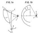
- FIGS. 1 a and 1 ban explanatory views respectively showing a device of example 1 according to the present invention viewed from a side and upper direction;
- FIGS. 2 a and 2 barm explanatory views respectively showing a device of example 2 according to the present invention viewed from a side and upper direction;
- FIGS. 3 a and 3 bare explanatory views respectively showing a device of example 3 according to the present invention viewed from a side and upper direction;
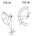
- FIGS. 4 a and 4 bare explanatory views respectively showing a device of example 4 according to the present invention viewed from a side and upper direction;
- FIGS. 5 a and 5 bare explanatory views respectively showing a device of example 5 according to the present invention viewed from a side and upper direction;
- FIGS. 6 a and 6 bare explanatory views respectively showing a device of example 6 according to the present invention viewed from a side and upper direction;
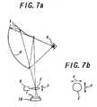
- FIG. 7 ais an explanatory view showing a device of example 7 according to the present invention viewed from a side
- FIG. 7 bis an explanatory view showing the movement of the lens 2 of the device of example 7 according to the present invention viewed from an upper direction;
- FIG. 8is an explanatory view showing an essential part of a device of example 8 according to the present invention viewed from a side direction;
- FIG. 9 ais an explanatory view showing a device of example 9 according to the present invention viewed from a side
- FIG. 9 bis an explanatory view showing the movement of the lens 2 of the device of example 9 according to the present invention viewed from upper direction;
- FIG. 10is an explanatory view showing a device of example 10 according to the present invention viewed from a side direction.
- FIGS. 1 to 10show a construction of the respective example for one eye according to the wide field of view head mounted display device of the present invention.
- FIGS 1 a and 1 bare explanatory views to show the device of example 1 according to the present invention in combination of a convex hyperboloidal mirror and a concave ellipsoidal mirror viewed respectively from a side and upper direction (or position).
- a beam of light from a LCD (liquid crystal display element) 1 as a display elementis projected as an incident light on a convex hyperboloidal mirror 3 by a lens 2 of a dioptric system.
- the principal point of the lens 2is located at a focus B of the hyperboloidal mirror 3 .
- FIGS. 2 a and 2 bare explanatory views to show the device of example 2 according to the present invention in combination of a convex parabolic mirror and a concave ellipsoidal mirror viewed respectively from a side and upper direction.
- a beam of light from the LCD 1 as a display elementis projected as an incident light on a convex parabolic mirror 6 by the lens 2 of a dioptric system.
- the lens 2in this case constitutes a dioptric system such as a telecentric lens, for example, by which rays of incident light are projected as parallel rays.
- FIGS. 3 a and 3 bare explanatory views to show the device of example 3 according to the present invention in combination of a convex spherical mirror and a concave ellipsoidal mirror viewed respectively from a side and upper direction
- a beam of light from the LCD 1 as a display elementis projected as an incident light on a convex spherical mirror 7 by the lens 2 of a dioptric system.
- FIGS. 4 a and 4 bare explanatory views to show the device of example 4 according to the present invention in combination of a convex hyperboloidal mirror and a concave spherical mirror viewed respectively from a side and upper direction.
- a beam of light from the LCD 1 as a display elementis projected as an incident light on the convex hyperboloidal mirror 3 by the lens 2 of a dioptric system.
- the principal point of the lens 2is placed at a focus B of the hyperboloidal mirror 3 .
- FIGS. 5 a and 5 bare explanatory views to show the device of example 5 according to the present invention in combination of a convex parabolic mirror and a concave spherical mirror viewed respectively from a side and upper direction.
- a beam of light from the LCD 1 as a display elementis projected as an incident light on a convex parabolic mirror 6 by the lens 2 of a dioptric system.
- the lens 2in this case constitutes a dioptric system such as a telecentric lens, for example, by which rays of incident light are projected as parallel rays.
- FIGS. 6 a and 6 bare explanatory views to show the device of example 6 according to the present invention in combination of a convex spherical mirror and concave spherical mirror viewed respectively from a side and upper direction
- a beam of light from the LCD 1 as a display elementis projected as an incident light on the convex spherical mirror 7 by the lens 2 of a dioptric system.
- FIG. 7 ais an explanatory view to show a device of example 7 according to the present invention viewed from a side, by which a relative positional relationship of a display element, a dioptric system and a catoptic system can be changed.
- FIG. 7 bis an explanatory view of the movement of the lens 2 of the device of example 7 viewed from an upper direction.
- the device of this exampleis equipped with a lens moving mechanism 9 as a physical relationship changing means that is a piezo-actuator, for example, this mechanism 9 changing the position of the lens 2 of the dioptric system to the three dimensional direction along axes x, y, and z as shown, and a LCD moving mechanism 10 as a physical relationship changing mechanism that is a piezo-actuator, for example, this mechanism 10 changing the position of the LCD 1 as a display element to the three dimensional direction along axes x, y and z as in the similar case of the lens 2 .
- a lens moving mechanism 9as a physical relationship changing means that is a piezo-actuator
- this mechanism 9changing the position of the lens 2 of the dioptric system to the three dimensional direction along axes x, y, and z as shown
- a LCD moving mechanism 10as a physical relationship changing mechanism that is a piezo-actuator, for example, this mechanism 10 changing the position of the LCD 1 as a display element to
- the LCD moving mechanism 10changes the position of the LCD 1 to the direction along x and/or y axis only for a distance less than one pitch of the pixels (half pitch, for example), by displacement of the pixels, the same effect as when number of pixels is increased can be obtained without movement of a position of the observing pupil 5 due to movement of the optical system, thereby resolution can be enhanced.
- the change of position of the LCD 1 along z axiscauses the focused point to change, and the focused point can be coincided with the observing position of an observer, thereby a fine image can be presented.
- the change of the position of the lens 2 to the direction along x, y and/or z axis by the lens moving mechanism 9displaces the projected position, and the displacement of pixels brings enhanced resolution similarly.
- the constitution of the optical system including the catoptric systemis changed and a light projected from the LCD 1 reflects on a concave mirror preventing itself from passing through a focus of the concave mirror, whereby the position of the observing pupil 5 is displaced a little bit from the position of the focus of the concave mirror and thereby eclipse by the iris can be dissolved.
- FIG. 8is an explanatory view of essential parts of the device of example 8 according to the present invention, by which a positional relationship of a display element and a dioptric system can be changed optically.
- a transparent plate 11comprising a conductive optical transparent material is disposed between the LCD 1 and lens 2 , as shown, in lieu of or in addition to the mechanical moving mechanisms 9 , 10 in the constitution of the example 7 above. Since refraction rate or orientation of this transparent plate 11 changes when a power is applied, the relative positional relationship of the LCD 1 and the lens 2 can be changed optically depending on number or thickness of the transparent plate 11 . Thereby resolution can be enhanced without changing the positional relationship between the lens 2 and the reflection mirror.
- FIG. 9 ais an explanatory view of the device of the example 9 viewed from a side, enabling to pick-up an image of the pupil by a half mirror.
- FIG. 9 bis an explanatory view showing from the upper direction the movement of the lens 2 of the device of the example 9.
- This device of this exampleis equipped with a half mirror 12 disposed between the LCD 1 and the lens 2 , and lens 13 and an imaging element 14 positioned at the side of the half mirror 12 in addition to the constitution of the example above (the constitution shown in FIG. 7 if shown), the lens 13 magnifying an image of an observing pupil 5 , and the imaging element 14 picking-up the image of it, thereby observation of the center of the pupil is made possible.
- the lens moving mechanism 9by controlling the position of the lens 2 to the convex mirror 3 by the lens moving mechanism 9 in order for the position of the pupil to be a center of the imaging element 14 , an image without eclipse can be presented.
- FIG. 10is also an explanatory view of the device of example 10 viewed from a side by which a pupil portion can be picked-up by a half mirror.
- the device of this exampleis equipped with the transparent plate 11 comprising a conductive optical transparent material disposed between the convex mirror 3 and the lens 2 in lieu of the lens moving mechanism 9 in the constitution of the example 9 shown in FIG. 9 . Since refraction rate or orientation of this conductive transparent plate 11 changes when a power is applied, the relative positional relationship among the reflection mirror and the couple of lens 2 and LCD 1 can be changed optically depending on number or thickness of the transparent plate 11 . With this constitution, by selecting the thickness of the conductive transparent plate 11 in order for the position of the pupil to be at a center of the imaging element 14 , an image without eclipse can be presented.
- any of the concave reflection mirrors(ellipsoidal mirror 4 and spherical mirror 8 ) in any of the examples has a size to bring 120 degree field of view horizontally per one eye and 180 or more degree by both eyes, and 60 degree field of view vertically per one eye.
- any of the convex reflection mirrors(hyperboloidal mirror 3 , parabolic mirror 6 and spherical mirror 7 ) in any of the examples has a size capable of projecting the reflected lights to substantially all area of the concave reflection mirrors above.
Landscapes
- Physics & Mathematics (AREA)
- General Physics & Mathematics (AREA)
- Optics & Photonics (AREA)
- Lenses (AREA)
- Liquid Crystal (AREA)
Abstract
Description
Claims (20)
Applications Claiming Priority (2)
| Application Number | Priority Date | Filing Date | Title |
|---|---|---|---|
| JP2002-256,377 | 2002-09-02 | ||
| JP2002256377AJP3755036B2 (en) | 2002-09-02 | 2002-09-02 | Wide viewing angle head mounted display device |
Publications (2)
| Publication Number | Publication Date |
|---|---|
| US20040070839A1 US20040070839A1 (en) | 2004-04-15 |
| US7088516B2true US7088516B2 (en) | 2006-08-08 |
Family
ID=32061617
Family Applications (1)
| Application Number | Title | Priority Date | Filing Date |
|---|---|---|---|
| US10/454,535Expired - LifetimeUS7088516B2 (en) | 2002-09-02 | 2003-06-05 | Wide field of view head mounted display device |
Country Status (3)
| Country | Link |
|---|---|
| US (1) | US7088516B2 (en) |
| JP (1) | JP3755036B2 (en) |
| CA (1) | CA2431127C (en) |
Cited By (34)
| Publication number | Priority date | Publication date | Assignee | Title |
|---|---|---|---|---|
| US20080199167A1 (en)* | 2007-02-21 | 2008-08-21 | Daly Scott J | Methods and Systems for Display Viewer Motion Compensation |
| US20080199049A1 (en)* | 2007-02-21 | 2008-08-21 | Daly Scott J | Methods and Systems for Display Viewer Motion Compensation Based on User Image Data |
| US8378924B2 (en) | 2007-01-12 | 2013-02-19 | Kopin Corporation | Monocular display device |
| US8467133B2 (en) | 2010-02-28 | 2013-06-18 | Osterhout Group, Inc. | See-through display with an optical assembly including a wedge-shaped illumination system |
| US8472120B2 (en) | 2010-02-28 | 2013-06-25 | Osterhout Group, Inc. | See-through near-eye display glasses with a small scale image source |
| US8477425B2 (en) | 2010-02-28 | 2013-07-02 | Osterhout Group, Inc. | See-through near-eye display glasses including a partially reflective, partially transmitting optical element |
| US8482859B2 (en) | 2010-02-28 | 2013-07-09 | Osterhout Group, Inc. | See-through near-eye display glasses wherein image light is transmitted to and reflected from an optically flat film |
| US8488246B2 (en) | 2010-02-28 | 2013-07-16 | Osterhout Group, Inc. | See-through near-eye display glasses including a curved polarizing film in the image source, a partially reflective, partially transmitting optical element and an optically flat film |
| US8814691B2 (en) | 2010-02-28 | 2014-08-26 | Microsoft Corporation | System and method for social networking gaming with an augmented reality |
| US9091851B2 (en) | 2010-02-28 | 2015-07-28 | Microsoft Technology Licensing, Llc | Light control in head mounted displays |
| US9097891B2 (en) | 2010-02-28 | 2015-08-04 | Microsoft Technology Licensing, Llc | See-through near-eye display glasses including an auto-brightness control for the display brightness based on the brightness in the environment |
| US9097890B2 (en) | 2010-02-28 | 2015-08-04 | Microsoft Technology Licensing, Llc | Grating in a light transmissive illumination system for see-through near-eye display glasses |
| US9129295B2 (en) | 2010-02-28 | 2015-09-08 | Microsoft Technology Licensing, Llc | See-through near-eye display glasses with a fast response photochromic film system for quick transition from dark to clear |
| US9128281B2 (en) | 2010-09-14 | 2015-09-08 | Microsoft Technology Licensing, Llc | Eyepiece with uniformly illuminated reflective display |
| US9134534B2 (en) | 2010-02-28 | 2015-09-15 | Microsoft Technology Licensing, Llc | See-through near-eye display glasses including a modular image source |
| US9182596B2 (en) | 2010-02-28 | 2015-11-10 | Microsoft Technology Licensing, Llc | See-through near-eye display glasses with the optical assembly including absorptive polarizers or anti-reflective coatings to reduce stray light |
| US9217868B2 (en) | 2007-01-12 | 2015-12-22 | Kopin Corporation | Monocular display device |
| US9223134B2 (en) | 2010-02-28 | 2015-12-29 | Microsoft Technology Licensing, Llc | Optical imperfections in a light transmissive illumination system for see-through near-eye display glasses |
| US9229227B2 (en) | 2010-02-28 | 2016-01-05 | Microsoft Technology Licensing, Llc | See-through near-eye display glasses with a light transmissive wedge shaped illumination system |
| US9237338B1 (en) | 2013-10-14 | 2016-01-12 | Simulated Percepts, Llc | Apparatus for image display with multi-focal length progressive lens or multiple discrete lenses each having different fixed focal lengths or a variable focal length |
| US9285589B2 (en) | 2010-02-28 | 2016-03-15 | Microsoft Technology Licensing, Llc | AR glasses with event and sensor triggered control of AR eyepiece applications |
| US20160109710A1 (en)* | 2014-10-17 | 2016-04-21 | Lockheed Martin Corporation | Head-wearable ultra-wide field of view display device |
| US9341843B2 (en) | 2010-02-28 | 2016-05-17 | Microsoft Technology Licensing, Llc | See-through near-eye display glasses with a small scale image source |
| US9366862B2 (en) | 2010-02-28 | 2016-06-14 | Microsoft Technology Licensing, Llc | System and method for delivering content to a group of see-through near eye display eyepieces |
| US9632315B2 (en) | 2010-10-21 | 2017-04-25 | Lockheed Martin Corporation | Head-mounted display apparatus employing one or more fresnel lenses |
| US9720228B2 (en) | 2010-12-16 | 2017-08-01 | Lockheed Martin Corporation | Collimating display with pixel lenses |
| US9759917B2 (en) | 2010-02-28 | 2017-09-12 | Microsoft Technology Licensing, Llc | AR glasses with event and sensor triggered AR eyepiece interface to external devices |
| US9939650B2 (en) | 2015-03-02 | 2018-04-10 | Lockheed Martin Corporation | Wearable display system |
| US9995936B1 (en) | 2016-04-29 | 2018-06-12 | Lockheed Martin Corporation | Augmented reality systems having a virtual image overlaying an infrared portion of a live scene |
| US10180572B2 (en) | 2010-02-28 | 2019-01-15 | Microsoft Technology Licensing, Llc | AR glasses with event and user action control of external applications |
| US10359545B2 (en) | 2010-10-21 | 2019-07-23 | Lockheed Martin Corporation | Fresnel lens with reduced draft facet visibility |
| US10539787B2 (en) | 2010-02-28 | 2020-01-21 | Microsoft Technology Licensing, Llc | Head-worn adaptive display |
| US10754156B2 (en) | 2015-10-20 | 2020-08-25 | Lockheed Martin Corporation | Multiple-eye, single-display, ultrawide-field-of-view optical see-through augmented reality system |
| US10860100B2 (en) | 2010-02-28 | 2020-12-08 | Microsoft Technology Licensing, Llc | AR glasses with predictive control of external device based on event input |
Families Citing this family (19)
| Publication number | Priority date | Publication date | Assignee | Title |
|---|---|---|---|---|
| JP4595485B2 (en)* | 2004-10-18 | 2010-12-08 | パナソニック電工株式会社 | Video display system |
| JP2008227834A (en)* | 2007-03-12 | 2008-09-25 | Osaka Univ | Head-mounted video presentation device, head-mounted imaging device, and head-mounted video device |
| US8403502B2 (en)* | 2008-11-18 | 2013-03-26 | Barco N.V. | Collimated visual display with elliptical front projection screen |
| JP2011059444A (en)* | 2009-09-10 | 2011-03-24 | Olympus Corp | Spectacles-type image display device |
| US9250444B2 (en) | 2009-11-21 | 2016-02-02 | Immy Inc. | Head mounted display device |
| FR2960309B1 (en)* | 2010-05-20 | 2013-06-28 | Delphi Tech Inc | HIGH HEAD DISPLAY SYSTEM |
| WO2013076994A1 (en)* | 2011-11-24 | 2013-05-30 | パナソニック株式会社 | Head-mounted display device |
| CN103576303B (en)* | 2012-08-07 | 2016-04-06 | 堤维西交通工业股份有限公司 | Compound reflection and refraction multiple imaging device for vehicle |
| EP2972547B1 (en) | 2013-03-15 | 2024-10-23 | Immy Inc. | Head mounted display with non-pupil forming optical path |
| US10088683B2 (en)* | 2014-10-24 | 2018-10-02 | Tapuyihai (Shanghai) Intelligent Technology Co., Ltd. | Head worn displaying device employing mobile phone |
| EP3150109B1 (en) | 2015-09-30 | 2023-07-05 | Nidek Co., Ltd. | Fundus imaging device |
| US10353202B2 (en) | 2016-06-09 | 2019-07-16 | Microsoft Technology Licensing, Llc | Wrapped waveguide with large field of view |
| US20180168266A1 (en)* | 2016-12-20 | 2018-06-21 | Jeffrey Mervin Windover | Visor mirror system and method |
| FI128248B (en) | 2017-06-02 | 2020-01-31 | Dispelix Oy | Eyepiece for a personal display and personal display comprising such eyepiece |
| CN107247325A (en)* | 2017-08-11 | 2017-10-13 | 深圳市辰羿科技有限公司 | A kind of multi-functional magnified image device |
| JP2019184807A (en) | 2018-04-10 | 2019-10-24 | 株式会社ジャパンディスプレイ | Head mount display |
| US10962783B2 (en) | 2018-06-19 | 2021-03-30 | Apple Inc. | Electronic devices having electrically adjustable optical layers |
| US11169358B1 (en)* | 2018-06-29 | 2021-11-09 | Facebook Technologies, Llc | Varifocal projection display |
| US11899214B1 (en) | 2018-09-18 | 2024-02-13 | Apple Inc. | Head-mounted device with virtually shifted component locations using a double-folded light path |
Citations (8)
| Publication number | Priority date | Publication date | Assignee | Title |
|---|---|---|---|---|
| JPH07120679A (en) | 1993-10-22 | 1995-05-12 | Olympus Optical Co Ltd | Homocentric optical system |
| JPH08286144A (en) | 1995-04-14 | 1996-11-01 | Canon Inc | Image observation device and observation device using the same |
| JPH08286140A (en) | 1995-04-11 | 1996-11-01 | Canon Inc | Image display device |
| JPH09189880A (en) | 1996-01-08 | 1997-07-22 | Canon Inc | Image display device |
| US5959780A (en)* | 1996-04-15 | 1999-09-28 | Olympus Optical Co., Ltd. | Head-mounted display apparatus comprising a rotationally asymmetric surface |
| US5986812A (en)* | 1996-07-19 | 1999-11-16 | Olympus Optical Co. Ltd. | Image display apparatus |
| US6097542A (en)* | 1996-10-16 | 2000-08-01 | Olympus Optical Co., Ltd. | Optical system having reflecting surface of non-rotationally symmetric surface configuration |
| JP2001290102A (en) | 2000-01-31 | 2001-10-19 | Fujitsu Ltd | Display device |
- 2002
- 2002-09-02JPJP2002256377Apatent/JP3755036B2/ennot_activeExpired - Lifetime
- 2003
- 2003-06-05USUS10/454,535patent/US7088516B2/ennot_activeExpired - Lifetime
- 2003-06-05CACA002431127Apatent/CA2431127C/ennot_activeExpired - Fee Related
Patent Citations (9)
| Publication number | Priority date | Publication date | Assignee | Title |
|---|---|---|---|---|
| JPH07120679A (en) | 1993-10-22 | 1995-05-12 | Olympus Optical Co Ltd | Homocentric optical system |
| US5768039A (en)* | 1993-10-22 | 1998-06-16 | Olympus Optical Co., Ltd. | Head-mounted image display apparatus |
| JPH08286140A (en) | 1995-04-11 | 1996-11-01 | Canon Inc | Image display device |
| JPH08286144A (en) | 1995-04-14 | 1996-11-01 | Canon Inc | Image observation device and observation device using the same |
| JPH09189880A (en) | 1996-01-08 | 1997-07-22 | Canon Inc | Image display device |
| US5959780A (en)* | 1996-04-15 | 1999-09-28 | Olympus Optical Co., Ltd. | Head-mounted display apparatus comprising a rotationally asymmetric surface |
| US5986812A (en)* | 1996-07-19 | 1999-11-16 | Olympus Optical Co. Ltd. | Image display apparatus |
| US6097542A (en)* | 1996-10-16 | 2000-08-01 | Olympus Optical Co., Ltd. | Optical system having reflecting surface of non-rotationally symmetric surface configuration |
| JP2001290102A (en) | 2000-01-31 | 2001-10-19 | Fujitsu Ltd | Display device |
Non-Patent Citations (1)
| Title |
|---|
| Translated Office Action issued in Japanese Patent Application No. 2002-256377. |
Cited By (41)
| Publication number | Priority date | Publication date | Assignee | Title |
|---|---|---|---|---|
| US9217868B2 (en) | 2007-01-12 | 2015-12-22 | Kopin Corporation | Monocular display device |
| US8378924B2 (en) | 2007-01-12 | 2013-02-19 | Kopin Corporation | Monocular display device |
| US20080199049A1 (en)* | 2007-02-21 | 2008-08-21 | Daly Scott J | Methods and Systems for Display Viewer Motion Compensation Based on User Image Data |
| US7903166B2 (en) | 2007-02-21 | 2011-03-08 | Sharp Laboratories Of America, Inc. | Methods and systems for display viewer motion compensation based on user image data |
| US8120717B2 (en) | 2007-02-21 | 2012-02-21 | Sharp Laboratories Of America, Inc. | Methods and systems for display viewer motion compensation |
| US20080199167A1 (en)* | 2007-02-21 | 2008-08-21 | Daly Scott J | Methods and Systems for Display Viewer Motion Compensation |
| US9229227B2 (en) | 2010-02-28 | 2016-01-05 | Microsoft Technology Licensing, Llc | See-through near-eye display glasses with a light transmissive wedge shaped illumination system |
| US9759917B2 (en) | 2010-02-28 | 2017-09-12 | Microsoft Technology Licensing, Llc | AR glasses with event and sensor triggered AR eyepiece interface to external devices |
| US8482859B2 (en) | 2010-02-28 | 2013-07-09 | Osterhout Group, Inc. | See-through near-eye display glasses wherein image light is transmitted to and reflected from an optically flat film |
| US8488246B2 (en) | 2010-02-28 | 2013-07-16 | Osterhout Group, Inc. | See-through near-eye display glasses including a curved polarizing film in the image source, a partially reflective, partially transmitting optical element and an optically flat film |
| US8467133B2 (en) | 2010-02-28 | 2013-06-18 | Osterhout Group, Inc. | See-through display with an optical assembly including a wedge-shaped illumination system |
| US9091851B2 (en) | 2010-02-28 | 2015-07-28 | Microsoft Technology Licensing, Llc | Light control in head mounted displays |
| US9097891B2 (en) | 2010-02-28 | 2015-08-04 | Microsoft Technology Licensing, Llc | See-through near-eye display glasses including an auto-brightness control for the display brightness based on the brightness in the environment |
| US9097890B2 (en) | 2010-02-28 | 2015-08-04 | Microsoft Technology Licensing, Llc | Grating in a light transmissive illumination system for see-through near-eye display glasses |
| US9129295B2 (en) | 2010-02-28 | 2015-09-08 | Microsoft Technology Licensing, Llc | See-through near-eye display glasses with a fast response photochromic film system for quick transition from dark to clear |
| US10180572B2 (en) | 2010-02-28 | 2019-01-15 | Microsoft Technology Licensing, Llc | AR glasses with event and user action control of external applications |
| US9134534B2 (en) | 2010-02-28 | 2015-09-15 | Microsoft Technology Licensing, Llc | See-through near-eye display glasses including a modular image source |
| US9182596B2 (en) | 2010-02-28 | 2015-11-10 | Microsoft Technology Licensing, Llc | See-through near-eye display glasses with the optical assembly including absorptive polarizers or anti-reflective coatings to reduce stray light |
| US10268888B2 (en) | 2010-02-28 | 2019-04-23 | Microsoft Technology Licensing, Llc | Method and apparatus for biometric data capture |
| US8472120B2 (en) | 2010-02-28 | 2013-06-25 | Osterhout Group, Inc. | See-through near-eye display glasses with a small scale image source |
| US8814691B2 (en) | 2010-02-28 | 2014-08-26 | Microsoft Corporation | System and method for social networking gaming with an augmented reality |
| US10539787B2 (en) | 2010-02-28 | 2020-01-21 | Microsoft Technology Licensing, Llc | Head-worn adaptive display |
| US9285589B2 (en) | 2010-02-28 | 2016-03-15 | Microsoft Technology Licensing, Llc | AR glasses with event and sensor triggered control of AR eyepiece applications |
| US8477425B2 (en) | 2010-02-28 | 2013-07-02 | Osterhout Group, Inc. | See-through near-eye display glasses including a partially reflective, partially transmitting optical element |
| US9329689B2 (en) | 2010-02-28 | 2016-05-03 | Microsoft Technology Licensing, Llc | Method and apparatus for biometric data capture |
| US9341843B2 (en) | 2010-02-28 | 2016-05-17 | Microsoft Technology Licensing, Llc | See-through near-eye display glasses with a small scale image source |
| US9366862B2 (en) | 2010-02-28 | 2016-06-14 | Microsoft Technology Licensing, Llc | System and method for delivering content to a group of see-through near eye display eyepieces |
| US10860100B2 (en) | 2010-02-28 | 2020-12-08 | Microsoft Technology Licensing, Llc | AR glasses with predictive control of external device based on event input |
| US9875406B2 (en) | 2010-02-28 | 2018-01-23 | Microsoft Technology Licensing, Llc | Adjustable extension for temple arm |
| US9223134B2 (en) | 2010-02-28 | 2015-12-29 | Microsoft Technology Licensing, Llc | Optical imperfections in a light transmissive illumination system for see-through near-eye display glasses |
| US9128281B2 (en) | 2010-09-14 | 2015-09-08 | Microsoft Technology Licensing, Llc | Eyepiece with uniformly illuminated reflective display |
| US10495790B2 (en) | 2010-10-21 | 2019-12-03 | Lockheed Martin Corporation | Head-mounted display apparatus employing one or more Fresnel lenses |
| US9632315B2 (en) | 2010-10-21 | 2017-04-25 | Lockheed Martin Corporation | Head-mounted display apparatus employing one or more fresnel lenses |
| US10359545B2 (en) | 2010-10-21 | 2019-07-23 | Lockheed Martin Corporation | Fresnel lens with reduced draft facet visibility |
| US9720228B2 (en) | 2010-12-16 | 2017-08-01 | Lockheed Martin Corporation | Collimating display with pixel lenses |
| US9237338B1 (en) | 2013-10-14 | 2016-01-12 | Simulated Percepts, Llc | Apparatus for image display with multi-focal length progressive lens or multiple discrete lenses each having different fixed focal lengths or a variable focal length |
| US20160109710A1 (en)* | 2014-10-17 | 2016-04-21 | Lockheed Martin Corporation | Head-wearable ultra-wide field of view display device |
| US10684476B2 (en)* | 2014-10-17 | 2020-06-16 | Lockheed Martin Corporation | Head-wearable ultra-wide field of view display device |
| US9939650B2 (en) | 2015-03-02 | 2018-04-10 | Lockheed Martin Corporation | Wearable display system |
| US10754156B2 (en) | 2015-10-20 | 2020-08-25 | Lockheed Martin Corporation | Multiple-eye, single-display, ultrawide-field-of-view optical see-through augmented reality system |
| US9995936B1 (en) | 2016-04-29 | 2018-06-12 | Lockheed Martin Corporation | Augmented reality systems having a virtual image overlaying an infrared portion of a live scene |
Also Published As
| Publication number | Publication date |
|---|---|
| CA2431127A1 (en) | 2004-03-02 |
| US20040070839A1 (en) | 2004-04-15 |
| JP2004094005A (en) | 2004-03-25 |
| CA2431127C (en) | 2007-09-11 |
| JP3755036B2 (en) | 2006-03-15 |
Similar Documents
| Publication | Publication Date | Title |
|---|---|---|
| US7088516B2 (en) | Wide field of view head mounted display device | |
| US5384654A (en) | Image observation device | |
| US5625372A (en) | Compact compound magnified virtual image electronic display | |
| US5815741A (en) | Image observing apparatus and imaging apparatus utilizing the image observing apparatus | |
| TW528886B (en) | Viewing optical system, image display apparatus comprising the same, and helmet-type viewing optical device | |
| US4269476A (en) | Helmet-mounted display system | |
| EP0660155B1 (en) | Image display apparatus | |
| JP3865906B2 (en) | Image display device | |
| CN100429559C (en) | virtual image display device | |
| US20080252970A1 (en) | Stereoscopic display unit and stereoscopic vision observation device | |
| JP2001264681A (en) | Display device | |
| US6830331B2 (en) | Magnification viewer | |
| US6464361B2 (en) | Image display apparatus having three-dimensionally decentered optical path | |
| US8159528B2 (en) | Visual display apparatus | |
| JP3524569B2 (en) | Visual display device | |
| JP2000089157A (en) | Head mount display | |
| US7385767B2 (en) | Zoom optical system, and electronic equipment incorporating the same | |
| JP3542213B2 (en) | Image display device | |
| US7177080B2 (en) | Method and a device for bi-monocular image transfer | |
| KR20010048012A (en) | Optical System for Head Mount Display | |
| CN119620418B (en) | Optical system and head-mounted display device | |
| TWI314219B (en) | ||
| KR20010081303A (en) | Optical System for Head Mount Display | |
| JP4592884B2 (en) | Image display device having three-dimensional eccentric optical path | |
| JP2001013450A (en) | Video display device |
Legal Events
| Date | Code | Title | Description |
|---|---|---|---|
| AS | Assignment | Owner name:OSAKA UNIVERSITY, JAPAN Free format text:ASSIGNMENT OF ASSIGNORS INTEREST;ASSIGNORS:YAGI, YASUSHI;YACHIDA, MASAHIKO;NAGAHARA, HAJIME;REEL/FRAME:014017/0017 Effective date:20030811 | |
| STCF | Information on status: patent grant | Free format text:PATENTED CASE | |
| FPAY | Fee payment | Year of fee payment:4 | |
| FEPP | Fee payment procedure | Free format text:PAT HOLDER NO LONGER CLAIMS SMALL ENTITY STATUS, ENTITY STATUS SET TO UNDISCOUNTED (ORIGINAL EVENT CODE: STOL); ENTITY STATUS OF PATENT OWNER: LARGE ENTITY | |
| FEPP | Fee payment procedure | Free format text:PAYOR NUMBER ASSIGNED (ORIGINAL EVENT CODE: ASPN); ENTITY STATUS OF PATENT OWNER: LARGE ENTITY | |
| AS | Assignment | Owner name:RAKUTEN, INC., JAPAN Free format text:ASSIGNMENT OF ASSIGNORS INTEREST;ASSIGNOR:OSAKA UNIVERSITY;REEL/FRAME:029665/0956 Effective date:20121107 | |
| FPAY | Fee payment | Year of fee payment:8 | |
| AS | Assignment | Owner name:RAKUTEN, INC., JAPAN Free format text:CHANGE OF ADDRESS;ASSIGNOR:RAKUTEN, INC.;REEL/FRAME:037751/0006 Effective date:20150824 | |
| MAFP | Maintenance fee payment | Free format text:PAYMENT OF MAINTENANCE FEE, 12TH YEAR, LARGE ENTITY (ORIGINAL EVENT CODE: M1553) Year of fee payment:12 | |
| AS | Assignment | Owner name:RAKUTEN GROUP, INC., JAPAN Free format text:CHANGE OF NAME;ASSIGNOR:RAKUTEN, INC.;REEL/FRAME:058314/0657 Effective date:20210901 | |
| AS | Assignment | Owner name:RAKUTEN GROUP, INC., JAPAN Free format text:CORRECTIVE ASSIGNMENT TO CORRECT THE REMOVE PATENT NUMBERS 10342096;10671117; 10716375; 10716376;10795407;10795408; AND 10827591 PREVIOUSLY RECORDED AT REEL: 58314 FRAME: 657. ASSIGNOR(S) HEREBY CONFIRMS THE ASSIGNMENT;ASSIGNOR:RAKUTEN, INC.;REEL/FRAME:068066/0103 Effective date:20210901 |