US7087458B2 - Method for fabricating a flip chip package with pillar bump and no flow underfill - Google Patents
Method for fabricating a flip chip package with pillar bump and no flow underfillDownload PDFInfo
- Publication number
- US7087458B2 US7087458B2US10/283,436US28343602AUS7087458B2US 7087458 B2US7087458 B2US 7087458B2US 28343602 AUS28343602 AUS 28343602AUS 7087458 B2US7087458 B2US 7087458B2
- Authority
- US
- United States
- Prior art keywords
- substrate
- solder
- group
- flow underfill
- flip chip
- Prior art date
- Legal status (The legal status is an assumption and is not a legal conclusion. Google has not performed a legal analysis and makes no representation as to the accuracy of the status listed.)
- Expired - Lifetime, expires
Links
Images

Classifications
- H—ELECTRICITY
- H01—ELECTRIC ELEMENTS
- H01L—SEMICONDUCTOR DEVICES NOT COVERED BY CLASS H10
- H01L21/00—Processes or apparatus adapted for the manufacture or treatment of semiconductor or solid state devices or of parts thereof
- H01L21/02—Manufacture or treatment of semiconductor devices or of parts thereof
- H01L21/04—Manufacture or treatment of semiconductor devices or of parts thereof the devices having potential barriers, e.g. a PN junction, depletion layer or carrier concentration layer
- H01L21/50—Assembly of semiconductor devices using processes or apparatus not provided for in a single one of the groups H01L21/18 - H01L21/326 or H10D48/04 - H10D48/07 e.g. sealing of a cap to a base of a container
- H01L21/56—Encapsulations, e.g. encapsulation layers, coatings
- H01L21/563—Encapsulation of active face of flip-chip device, e.g. underfilling or underencapsulation of flip-chip, encapsulation preform on chip or mounting substrate
- H—ELECTRICITY
- H01—ELECTRIC ELEMENTS
- H01L—SEMICONDUCTOR DEVICES NOT COVERED BY CLASS H10
- H01L23/00—Details of semiconductor or other solid state devices
- H01L23/48—Arrangements for conducting electric current to or from the solid state body in operation, e.g. leads, terminal arrangements ; Selection of materials therefor
- H01L23/488—Arrangements for conducting electric current to or from the solid state body in operation, e.g. leads, terminal arrangements ; Selection of materials therefor consisting of soldered or bonded constructions
- H01L23/498—Leads, i.e. metallisations or lead-frames on insulating substrates, e.g. chip carriers
- H01L23/49811—Additional leads joined to the metallisation on the insulating substrate, e.g. pins, bumps, wires, flat leads
- H01L23/49816—Spherical bumps on the substrate for external connection, e.g. ball grid arrays [BGA]
- H—ELECTRICITY
- H01—ELECTRIC ELEMENTS
- H01L—SEMICONDUCTOR DEVICES NOT COVERED BY CLASS H10
- H01L24/00—Arrangements for connecting or disconnecting semiconductor or solid-state bodies; Methods or apparatus related thereto
- H01L24/01—Means for bonding being attached to, or being formed on, the surface to be connected, e.g. chip-to-package, die-attach, "first-level" interconnects; Manufacturing methods related thereto
- H01L24/26—Layer connectors, e.g. plate connectors, solder or adhesive layers; Manufacturing methods related thereto
- H01L24/28—Structure, shape, material or disposition of the layer connectors prior to the connecting process
- H01L24/29—Structure, shape, material or disposition of the layer connectors prior to the connecting process of an individual layer connector
- H—ELECTRICITY
- H01—ELECTRIC ELEMENTS
- H01L—SEMICONDUCTOR DEVICES NOT COVERED BY CLASS H10
- H01L2224/00—Indexing scheme for arrangements for connecting or disconnecting semiconductor or solid-state bodies and methods related thereto as covered by H01L24/00
- H01L2224/01—Means for bonding being attached to, or being formed on, the surface to be connected, e.g. chip-to-package, die-attach, "first-level" interconnects; Manufacturing methods related thereto
- H01L2224/02—Bonding areas; Manufacturing methods related thereto
- H01L2224/04—Structure, shape, material or disposition of the bonding areas prior to the connecting process
- H01L2224/05—Structure, shape, material or disposition of the bonding areas prior to the connecting process of an individual bonding area
- H01L2224/0554—External layer
- H01L2224/05573—Single external layer
- H—ELECTRICITY
- H01—ELECTRIC ELEMENTS
- H01L—SEMICONDUCTOR DEVICES NOT COVERED BY CLASS H10
- H01L2224/00—Indexing scheme for arrangements for connecting or disconnecting semiconductor or solid-state bodies and methods related thereto as covered by H01L24/00
- H01L2224/01—Means for bonding being attached to, or being formed on, the surface to be connected, e.g. chip-to-package, die-attach, "first-level" interconnects; Manufacturing methods related thereto
- H01L2224/10—Bump connectors; Manufacturing methods related thereto
- H01L2224/12—Structure, shape, material or disposition of the bump connectors prior to the connecting process
- H01L2224/13—Structure, shape, material or disposition of the bump connectors prior to the connecting process of an individual bump connector
- H01L2224/13001—Core members of the bump connector
- H01L2224/13075—Plural core members
- H01L2224/1308—Plural core members being stacked
- H—ELECTRICITY
- H01—ELECTRIC ELEMENTS
- H01L—SEMICONDUCTOR DEVICES NOT COVERED BY CLASS H10
- H01L2224/00—Indexing scheme for arrangements for connecting or disconnecting semiconductor or solid-state bodies and methods related thereto as covered by H01L24/00
- H01L2224/01—Means for bonding being attached to, or being formed on, the surface to be connected, e.g. chip-to-package, die-attach, "first-level" interconnects; Manufacturing methods related thereto
- H01L2224/10—Bump connectors; Manufacturing methods related thereto
- H01L2224/12—Structure, shape, material or disposition of the bump connectors prior to the connecting process
- H01L2224/13—Structure, shape, material or disposition of the bump connectors prior to the connecting process of an individual bump connector
- H01L2224/13001—Core members of the bump connector
- H01L2224/13099—Material
- H01L2224/131—Material with a principal constituent of the material being a metal or a metalloid, e.g. boron [B], silicon [Si], germanium [Ge], arsenic [As], antimony [Sb], tellurium [Te] and polonium [Po], and alloys thereof
- H01L2224/13101—Material with a principal constituent of the material being a metal or a metalloid, e.g. boron [B], silicon [Si], germanium [Ge], arsenic [As], antimony [Sb], tellurium [Te] and polonium [Po], and alloys thereof the principal constituent melting at a temperature of less than 400°C
- H01L2224/13111—Tin [Sn] as principal constituent
- H—ELECTRICITY
- H01—ELECTRIC ELEMENTS
- H01L—SEMICONDUCTOR DEVICES NOT COVERED BY CLASS H10
- H01L2224/00—Indexing scheme for arrangements for connecting or disconnecting semiconductor or solid-state bodies and methods related thereto as covered by H01L24/00
- H01L2224/01—Means for bonding being attached to, or being formed on, the surface to be connected, e.g. chip-to-package, die-attach, "first-level" interconnects; Manufacturing methods related thereto
- H01L2224/10—Bump connectors; Manufacturing methods related thereto
- H01L2224/15—Structure, shape, material or disposition of the bump connectors after the connecting process
- H01L2224/16—Structure, shape, material or disposition of the bump connectors after the connecting process of an individual bump connector
- H01L2224/161—Disposition
- H01L2224/16151—Disposition the bump connector connecting between a semiconductor or solid-state body and an item not being a semiconductor or solid-state body, e.g. chip-to-substrate, chip-to-passive
- H01L2224/16221—Disposition the bump connector connecting between a semiconductor or solid-state body and an item not being a semiconductor or solid-state body, e.g. chip-to-substrate, chip-to-passive the body and the item being stacked
- H01L2224/16225—Disposition the bump connector connecting between a semiconductor or solid-state body and an item not being a semiconductor or solid-state body, e.g. chip-to-substrate, chip-to-passive the body and the item being stacked the item being non-metallic, e.g. insulating substrate with or without metallisation
- H—ELECTRICITY
- H01—ELECTRIC ELEMENTS
- H01L—SEMICONDUCTOR DEVICES NOT COVERED BY CLASS H10
- H01L2224/00—Indexing scheme for arrangements for connecting or disconnecting semiconductor or solid-state bodies and methods related thereto as covered by H01L24/00
- H01L2224/01—Means for bonding being attached to, or being formed on, the surface to be connected, e.g. chip-to-package, die-attach, "first-level" interconnects; Manufacturing methods related thereto
- H01L2224/26—Layer connectors, e.g. plate connectors, solder or adhesive layers; Manufacturing methods related thereto
- H01L2224/28—Structure, shape, material or disposition of the layer connectors prior to the connecting process
- H01L2224/29—Structure, shape, material or disposition of the layer connectors prior to the connecting process of an individual layer connector
- H01L2224/29001—Core members of the layer connector
- H01L2224/29099—Material
- H01L2224/291—Material with a principal constituent of the material being a metal or a metalloid, e.g. boron [B], silicon [Si], germanium [Ge], arsenic [As], antimony [Sb], tellurium [Te] and polonium [Po], and alloys thereof
- H01L2224/29101—Material with a principal constituent of the material being a metal or a metalloid, e.g. boron [B], silicon [Si], germanium [Ge], arsenic [As], antimony [Sb], tellurium [Te] and polonium [Po], and alloys thereof the principal constituent melting at a temperature of less than 400°C
- H01L2224/29111—Tin [Sn] as principal constituent
- H—ELECTRICITY
- H01—ELECTRIC ELEMENTS
- H01L—SEMICONDUCTOR DEVICES NOT COVERED BY CLASS H10
- H01L2224/00—Indexing scheme for arrangements for connecting or disconnecting semiconductor or solid-state bodies and methods related thereto as covered by H01L24/00
- H01L2224/01—Means for bonding being attached to, or being formed on, the surface to be connected, e.g. chip-to-package, die-attach, "first-level" interconnects; Manufacturing methods related thereto
- H01L2224/26—Layer connectors, e.g. plate connectors, solder or adhesive layers; Manufacturing methods related thereto
- H01L2224/28—Structure, shape, material or disposition of the layer connectors prior to the connecting process
- H01L2224/29—Structure, shape, material or disposition of the layer connectors prior to the connecting process of an individual layer connector
- H01L2224/29001—Core members of the layer connector
- H01L2224/29099—Material
- H01L2224/2919—Material with a principal constituent of the material being a polymer, e.g. polyester, phenolic based polymer, epoxy
- H—ELECTRICITY
- H01—ELECTRIC ELEMENTS
- H01L—SEMICONDUCTOR DEVICES NOT COVERED BY CLASS H10
- H01L2224/00—Indexing scheme for arrangements for connecting or disconnecting semiconductor or solid-state bodies and methods related thereto as covered by H01L24/00
- H01L2224/73—Means for bonding being of different types provided for in two or more of groups H01L2224/10, H01L2224/18, H01L2224/26, H01L2224/34, H01L2224/42, H01L2224/50, H01L2224/63, H01L2224/71
- H01L2224/732—Location after the connecting process
- H01L2224/73201—Location after the connecting process on the same surface
- H01L2224/73203—Bump and layer connectors
- H01L2224/73204—Bump and layer connectors the bump connector being embedded into the layer connector
- H—ELECTRICITY
- H01—ELECTRIC ELEMENTS
- H01L—SEMICONDUCTOR DEVICES NOT COVERED BY CLASS H10
- H01L2224/00—Indexing scheme for arrangements for connecting or disconnecting semiconductor or solid-state bodies and methods related thereto as covered by H01L24/00
- H01L2224/74—Apparatus for manufacturing arrangements for connecting or disconnecting semiconductor or solid-state bodies and for methods related thereto
- H01L2224/75—Apparatus for connecting with bump connectors or layer connectors
- H01L2224/7525—Means for applying energy, e.g. heating means
- H01L2224/75252—Means for applying energy, e.g. heating means in the upper part of the bonding apparatus, e.g. in the bonding head
- H—ELECTRICITY
- H01—ELECTRIC ELEMENTS
- H01L—SEMICONDUCTOR DEVICES NOT COVERED BY CLASS H10
- H01L2224/00—Indexing scheme for arrangements for connecting or disconnecting semiconductor or solid-state bodies and methods related thereto as covered by H01L24/00
- H01L2224/80—Methods for connecting semiconductor or other solid state bodies using means for bonding being attached to, or being formed on, the surface to be connected
- H01L2224/81—Methods for connecting semiconductor or other solid state bodies using means for bonding being attached to, or being formed on, the surface to be connected using a bump connector
- H01L2224/8119—Arrangement of the bump connectors prior to mounting
- H01L2224/81193—Arrangement of the bump connectors prior to mounting wherein the bump connectors are disposed on both the semiconductor or solid-state body and another item or body to be connected to the semiconductor or solid-state body
- H—ELECTRICITY
- H01—ELECTRIC ELEMENTS
- H01L—SEMICONDUCTOR DEVICES NOT COVERED BY CLASS H10
- H01L2224/00—Indexing scheme for arrangements for connecting or disconnecting semiconductor or solid-state bodies and methods related thereto as covered by H01L24/00
- H01L2224/80—Methods for connecting semiconductor or other solid state bodies using means for bonding being attached to, or being formed on, the surface to be connected
- H01L2224/83—Methods for connecting semiconductor or other solid state bodies using means for bonding being attached to, or being formed on, the surface to be connected using a layer connector
- H01L2224/8319—Arrangement of the layer connectors prior to mounting
- H01L2224/83192—Arrangement of the layer connectors prior to mounting wherein the layer connectors are disposed only on another item or body to be connected to the semiconductor or solid-state body
- H—ELECTRICITY
- H01—ELECTRIC ELEMENTS
- H01L—SEMICONDUCTOR DEVICES NOT COVERED BY CLASS H10
- H01L2924/00—Indexing scheme for arrangements or methods for connecting or disconnecting semiconductor or solid-state bodies as covered by H01L24/00
- H01L2924/01—Chemical elements
- H01L2924/01005—Boron [B]
- H—ELECTRICITY
- H01—ELECTRIC ELEMENTS
- H01L—SEMICONDUCTOR DEVICES NOT COVERED BY CLASS H10
- H01L2924/00—Indexing scheme for arrangements or methods for connecting or disconnecting semiconductor or solid-state bodies as covered by H01L24/00
- H01L2924/01—Chemical elements
- H01L2924/01006—Carbon [C]
- H—ELECTRICITY
- H01—ELECTRIC ELEMENTS
- H01L—SEMICONDUCTOR DEVICES NOT COVERED BY CLASS H10
- H01L2924/00—Indexing scheme for arrangements or methods for connecting or disconnecting semiconductor or solid-state bodies as covered by H01L24/00
- H01L2924/01—Chemical elements
- H01L2924/01013—Aluminum [Al]
- H—ELECTRICITY
- H01—ELECTRIC ELEMENTS
- H01L—SEMICONDUCTOR DEVICES NOT COVERED BY CLASS H10
- H01L2924/00—Indexing scheme for arrangements or methods for connecting or disconnecting semiconductor or solid-state bodies as covered by H01L24/00
- H01L2924/01—Chemical elements
- H01L2924/01023—Vanadium [V]
- H—ELECTRICITY
- H01—ELECTRIC ELEMENTS
- H01L—SEMICONDUCTOR DEVICES NOT COVERED BY CLASS H10
- H01L2924/00—Indexing scheme for arrangements or methods for connecting or disconnecting semiconductor or solid-state bodies as covered by H01L24/00
- H01L2924/01—Chemical elements
- H01L2924/01024—Chromium [Cr]
- H—ELECTRICITY
- H01—ELECTRIC ELEMENTS
- H01L—SEMICONDUCTOR DEVICES NOT COVERED BY CLASS H10
- H01L2924/00—Indexing scheme for arrangements or methods for connecting or disconnecting semiconductor or solid-state bodies as covered by H01L24/00
- H01L2924/01—Chemical elements
- H01L2924/01029—Copper [Cu]
- H—ELECTRICITY
- H01—ELECTRIC ELEMENTS
- H01L—SEMICONDUCTOR DEVICES NOT COVERED BY CLASS H10
- H01L2924/00—Indexing scheme for arrangements or methods for connecting or disconnecting semiconductor or solid-state bodies as covered by H01L24/00
- H01L2924/01—Chemical elements
- H01L2924/01033—Arsenic [As]
- H—ELECTRICITY
- H01—ELECTRIC ELEMENTS
- H01L—SEMICONDUCTOR DEVICES NOT COVERED BY CLASS H10
- H01L2924/00—Indexing scheme for arrangements or methods for connecting or disconnecting semiconductor or solid-state bodies as covered by H01L24/00
- H01L2924/01—Chemical elements
- H01L2924/0105—Tin [Sn]
- H—ELECTRICITY
- H01—ELECTRIC ELEMENTS
- H01L—SEMICONDUCTOR DEVICES NOT COVERED BY CLASS H10
- H01L2924/00—Indexing scheme for arrangements or methods for connecting or disconnecting semiconductor or solid-state bodies as covered by H01L24/00
- H01L2924/01—Chemical elements
- H01L2924/01078—Platinum [Pt]
- H—ELECTRICITY
- H01—ELECTRIC ELEMENTS
- H01L—SEMICONDUCTOR DEVICES NOT COVERED BY CLASS H10
- H01L2924/00—Indexing scheme for arrangements or methods for connecting or disconnecting semiconductor or solid-state bodies as covered by H01L24/00
- H01L2924/01—Chemical elements
- H01L2924/01079—Gold [Au]
- H—ELECTRICITY
- H01—ELECTRIC ELEMENTS
- H01L—SEMICONDUCTOR DEVICES NOT COVERED BY CLASS H10
- H01L2924/00—Indexing scheme for arrangements or methods for connecting or disconnecting semiconductor or solid-state bodies as covered by H01L24/00
- H01L2924/01—Chemical elements
- H01L2924/01082—Lead [Pb]
- H—ELECTRICITY
- H01—ELECTRIC ELEMENTS
- H01L—SEMICONDUCTOR DEVICES NOT COVERED BY CLASS H10
- H01L2924/00—Indexing scheme for arrangements or methods for connecting or disconnecting semiconductor or solid-state bodies as covered by H01L24/00
- H01L2924/013—Alloys
- H01L2924/0132—Binary Alloys
- H—ELECTRICITY
- H01—ELECTRIC ELEMENTS
- H01L—SEMICONDUCTOR DEVICES NOT COVERED BY CLASS H10
- H01L2924/00—Indexing scheme for arrangements or methods for connecting or disconnecting semiconductor or solid-state bodies as covered by H01L24/00
- H01L2924/013—Alloys
- H01L2924/0132—Binary Alloys
- H01L2924/01322—Eutectic Alloys, i.e. obtained by a liquid transforming into two solid phases
- H—ELECTRICITY
- H01—ELECTRIC ELEMENTS
- H01L—SEMICONDUCTOR DEVICES NOT COVERED BY CLASS H10
- H01L2924/00—Indexing scheme for arrangements or methods for connecting or disconnecting semiconductor or solid-state bodies as covered by H01L24/00
- H01L2924/013—Alloys
- H01L2924/0133—Ternary Alloys
- H—ELECTRICITY
- H01—ELECTRIC ELEMENTS
- H01L—SEMICONDUCTOR DEVICES NOT COVERED BY CLASS H10
- H01L2924/00—Indexing scheme for arrangements or methods for connecting or disconnecting semiconductor or solid-state bodies as covered by H01L24/00
- H01L2924/10—Details of semiconductor or other solid state devices to be connected
- H01L2924/11—Device type
- H01L2924/14—Integrated circuits
- H—ELECTRICITY
- H01—ELECTRIC ELEMENTS
- H01L—SEMICONDUCTOR DEVICES NOT COVERED BY CLASS H10
- H01L2924/00—Indexing scheme for arrangements or methods for connecting or disconnecting semiconductor or solid-state bodies as covered by H01L24/00
- H01L2924/15—Details of package parts other than the semiconductor or other solid state devices to be connected
- H01L2924/151—Die mounting substrate
- H01L2924/153—Connection portion
- H01L2924/1531—Connection portion the connection portion being formed only on the surface of the substrate opposite to the die mounting surface
- H01L2924/15311—Connection portion the connection portion being formed only on the surface of the substrate opposite to the die mounting surface being a ball array, e.g. BGA
Definitions
- the present inventionrelates generally to semiconductor packaging and more specifically to fabrication of a flip chip configured microelectronic package interconnected via a combination of a no flow underfill and pillar bump.
- the present inventionprovides a method for fabricating a high density fine-pitch flip chip package structure using pillar bump interconnect technology incorporating low CTE no flow underfill as related to the manufacture of electronic components.
- U.S. Pat. No. 6,083,773 to Lakediscloses a method for forming flip chip bumps and related flip chip bump constructions.
- a methodfor joining a semiconductor IC chip in a flip chip configuration via a combination of no flow underfill and pillar bump to solderable metal contact pads, leads, or circuit lines on the personalized surface of a chip carrier substrate as well as the resulting chip package
- the substratemay comprise any of the following: ceramic material, rigid or flexible polymeric laminate.
- the substrateis personalized with conductive electrodes/terminals and a silica filled low CTE no flow underfill layer is deposited on the substrate.
- the semiconductor deviceis positioned with inteconnecting solder bumps aligned with terminal pads, after which the IC chip and substrate are brought together under thermal compression bonding.
- FIG. 1 ais a cross-sectional representation of the invention, showing a semiconductor device (IC) having a pillar bump structure with a free-end solder portion.
- ICsemiconductor device
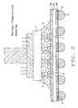
- FIG. 1 bis a cross-sectional representation of the invention, showing a substrate having an insulating base layer, patterned layers of conductors, layers of solder mask and underfill layer.
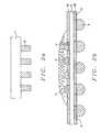
- FIG. 2 ais a cross-sectional representation of the invention showing a semiconductor device (IC) having a pillar bump structure only.
- FIG. 2 bis a cross-sectional representation of the invention illustrating a substrate having an insulating base layer, patterned layers of conductors capped with a free-end solder portion, layers of solder mask and underfill layer.
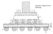
- FIG. 3is a cross-sectional representation of a preferred embodiment of the present invention formed under thermal compression bonding.
- thermomechanical stress buildup at the interconnect joint resulting from CTE mismatch between chip and substrate1.
- Fine pitch wiring requirementshave introduced process complexity, reduced yields to the capillary underfill process.
- Lead free solder as flip chip bumping materialhas a higher melting point compared to their tin lead counterpart. It is thus imperative that no flow underfill have stronger fluxing properties even at higher temperatures, for instance 220° C.-230° C.
- properties that are required for a good fluxare not totally compatible with that required for good underfill. It has been observed that serious voids are generated during lead free solder reflow process through reflow oven, which probably resulted from reaction between molten solder and certain components inside the underfill material. Thus, the properties that are required for a good flux is not totally compatible with that required with a good underfill.
- Structure 1is preferably a semiconductor structure and is also understood to possibly include a semiconductor wafer or substrate, active and passive devices formed within the wafer, conductive layers and dielectric layers (e.g., inter-poly oxide (IPO), intermetal dielectric (IMD), etc.) formed over the wafer surface.
- semiconductor structureis meant to include devices formed within a semiconductor wafer and the layers overlying the wafer.
- Pillar bump cross-sectional structurecomprises a base portion 2 and a free-end portion 3 .
- the base portion 2may comprise any non-reflowable material, but is preferably comprised of copper.
- the free end portion 3is composed of a reflowable material, and is preferably deposited tin-lead eutectic solder, or lead-free solder. Formation of the pillar bump structure is described in U.S. patent application Publication 2002/0033412A1, herein incorporated by reference.
- FIG. 1 bis a cross-sectional representation of a substrate having a non-conductive base layer 8 which can be composed of a ceramic material (e.g., alumina) or an organic rigid or flexible laminate dielectric material, such as, polyimide or benzocyclobutene. Furthermore FIG. 1 b illustrates patterned layers of conductor 6 preferably comprised of copper pads on which are deposited C-4 BGA solder balls 9 , formed in openings in solder mask passivation layer 4 b.
- a ceramic materiale.g., alumina
- an organic rigid or flexible laminate dielectric materialsuch as, polyimide or benzocyclobutene.
- FIG. 1 billustrates patterned layers of conductor 6 preferably comprised of copper pads on which are deposited C-4 BGA solder balls 9 , formed in openings in solder mask passivation layer 4 b.
- Silica filled low CTE no flow underfill layer 5is deposited on the substrate.
- Bonding or terminal pad 7is preferably comprised of copper and is designed to protrude above solder mask 4 a , to facilitate contact with bump during bonding.
- Semiconductor IC 1is positioned with bumps aligned with bonding or terminal pad 7 so that IC and substrate are brought together under thermal compression bonding.
- FIG. 2 ais an alternative structure for the current invention, whereby the pillar bump structure comprises portion 2 only, preferably non-reflowable copper.
- FIG. 2 bis a cross-sectional view illustrating reflowable solder material 3 which is applied to electrode 7 during substrate manufacturing.
- Deposition processis applied by printing/electrolytic plating, but is preferably via electrolytic plating in fine-pitch application.
- FIG. 3is a cross-sectional view of the preferred structure of the invention.
- FIG. 3illustrates a flip chip package formed with pillar bump and no flow underfill in accordance with the present invention. It further shows that at an elevated reflow temperature range under force, the free-end solder portion 3 melts and pushes away silica filler to form an interconnect between IC chip and substrate.
- FIGS. 1 , 2 and 3The process of the invention may be understood with respect to FIGS. 1 , 2 and 3 .
- the structure of FIG. 1 ais joined with the structure of FIG. 1 b by thermal compression bonding by applying temperature, pressure and time.
- FIG. 1 bis comprised of a ceramic or an organic nonconductive substrate on which patterned layers of Cu are formed where underlying Cr or Ti adhesion layers may be used. Ni/Au coating or osp (organic solder preservative) protection are normally applied.
- Silica filled low CTE no flow underfillis deposited on the substrate by, for example, a standard dispensing or printing technique.
- the semiconductor device/ICis positioned such that the pillar bumps as shown in FIG. 1 a are aligned with the terminal conductor pads of FIG.
- the terminal conductive padsare designed to be above the solder mask to facilitate contact with pillar bumps during bonding.
- the free-end solder portion 3 of the pillar bumpmelts and pushes away silica filler to form an interconnect between IC chip and substrate.
- the semiconductor device/ICis positioned such that the pillar structure as shown in FIG. 2 a is aligned with the solder capped bumps of terminal conductor pads of FIG. 2 b after which the IC and substrate are brought together under thermal compression bonding at a controlled temperature pressure and time.
- solder capped terminal conductive padsare designed to be above the solder mask to facilitate contact with the pillars of FIG. 2 a during bonding.
- the free-end solder portion 3 of the substratemelts and pushes away silica filler to wet the pillar to form an interconnect between IC chip and substrate.
- FIG. 3A flip chip package formed with pillar bump or solder capped substrate electrodes and no flow underfill in accordance with the present invention is shown by FIG. 3 .
Landscapes
- Engineering & Computer Science (AREA)
- Computer Hardware Design (AREA)
- Microelectronics & Electronic Packaging (AREA)
- Power Engineering (AREA)
- Physics & Mathematics (AREA)
- Condensed Matter Physics & Semiconductors (AREA)
- General Physics & Mathematics (AREA)
- Manufacturing & Machinery (AREA)
- Wire Bonding (AREA)
Abstract
Description
The present invention relates generally to semiconductor packaging and more specifically to fabrication of a flip chip configured microelectronic package interconnected via a combination of a no flow underfill and pillar bump.
As current and future microelectronic packaging requirements trend towards miniaturization the demand for denser, lighter, smaller, thinner and faster electronic products continues. The present invention provides a method for fabricating a high density fine-pitch flip chip package structure using pillar bump interconnect technology incorporating low CTE no flow underfill as related to the manufacture of electronic components.
U.S. Pat. No. 6,392,163 to Rinne et al. describes a method for controlling height, shape and volume of solder bump interconnects.
U.S. Pat. No. 6,184,062 to Brofman et al. discloses a process for forming cone shaped solder for chip interconnection.
U.S. Pat. No. 6,131,795 to Sato shows a thermal compression bonding method of an electronic die with solder bump.
U.S. Pat. No. 6,114,187 to Hayes describes a method of preparing column of solder bumps for chip scale package.
U.S. Pat. No. 6,083,773 to Lake discloses a method for forming flip chip bumps and related flip chip bump constructions.
U.S. Pat. No. 5,587,337 to Idaka et al. shows a semiconductor process for forming bump electrodes with tapered sidewalls.
It is therefore an object of the present invention to provide a structure and method for the fabrication of a fine-pitch flip chip package.
It is another object of the invention to provide a means for realizing a high assembly yield for lead free bumped flip chip package.
In yet another objective of the present invention is to incorporate low CTE no flow underfill layer into the flip chip package to deliver better reliability.
In order to accomplish these and other objectives of the invention, a method is provided for joining a semiconductor IC chip in a flip chip configuration via a combination of no flow underfill and pillar bump to solderable metal contact pads, leads, or circuit lines on the personalized surface of a chip carrier substrate as well as the resulting chip package
In accordance with the present invention the substrate may comprise any of the following: ceramic material, rigid or flexible polymeric laminate. The substrate is personalized with conductive electrodes/terminals and a silica filled low CTE no flow underfill layer is deposited on the substrate. Next the semiconductor device is positioned with inteconnecting solder bumps aligned with terminal pads, after which the IC chip and substrate are brought together under thermal compression bonding.
The foregoing and other objects, aspects and advantages of the present invention will be more clearly understood from the following detailed description taken in conjunction with the accompanying drawings. The drawing illustrate like reference numerals designating similar or corresponding elements, regions and portions and in which:
Problems Discovered by the Inventors
The inventors have discovered the following problems and disadvantages with the current practice:
1. For flip chip packaging structures thermomechanical stress buildup at the interconnect joint resulting from CTE mismatch between chip and substrate.
2. Flip chip structures utilizing spherical reflowable solder bumps and capillary underfill have been limited in meeting fine pitch wiring requirements. In order to overcome current fine pitch wiring limitations solder bump size reduction must be introduced which than results in reduced stand-off causing underfill difficulty.
3. Fine pitch wiring requirements have introduced process complexity, reduced yields to the capillary underfill process.
4. Loading percentage of Silica filler into no flow underfill is extremely limited due to trapped silica between solder bumps and I/O pads.
5. Lead free solder as flip chip bumping material has a higher melting point compared to their tin lead counterpart. It is thus imperative that no flow underfill have stronger fluxing properties even at higher temperatures, for instance 220° C.-230° C. Unfortunately, properties that are required for a good flux are not totally compatible with that required for good underfill. It has been observed that serious voids are generated during lead free solder reflow process through reflow oven, which probably resulted from reaction between molten solder and certain components inside the underfill material. Thus, the properties that are required for a good flux is not totally compatible with that required with a good underfill.
6. The process as practiced in the current art using non-filled high CTE no flow underfill lends to exposure to reduced yields, and short/long term reliability performance issues in large die, high density applications.
Initial Structure
Referring to the drawings, and more particularly toFIG. 1 a, there is shown a cross-sectional view of semiconductor IC1 with pillar bumps provided. Structure1 is preferably a semiconductor structure and is also understood to possibly include a semiconductor wafer or substrate, active and passive devices formed within the wafer, conductive layers and dielectric layers (e.g., inter-poly oxide (IPO), intermetal dielectric (IMD), etc.) formed over the wafer surface. The term “semiconductor structure” is meant to include devices formed within a semiconductor wafer and the layers overlying the wafer.
Pillar bump cross-sectional structure comprises abase portion 2 and a free-end portion 3. Thebase portion 2 may comprise any non-reflowable material, but is preferably comprised of copper. Thefree end portion 3 is composed of a reflowable material, and is preferably deposited tin-lead eutectic solder, or lead-free solder. Formation of the pillar bump structure is described in U.S. patent application Publication 2002/0033412A1, herein incorporated by reference.
Silica filled low CTE noflow underfill layer 5 is deposited on the substrate.
Bonding orterminal pad 7 is preferably comprised of copper and is designed to protrude above solder mask4a, to facilitate contact with bump during bonding. Semiconductor IC1 is positioned with bumps aligned with bonding orterminal pad 7 so that IC and substrate are brought together under thermal compression bonding.
Key Steps of the Invention
The process of the invention may be understood with respect toFIGS. 1 ,2 and3. The structure ofFIG. 1 ais joined with the structure ofFIG. 1 bby thermal compression bonding by applying temperature, pressure and time.FIG. 1 bis comprised of a ceramic or an organic nonconductive substrate on which patterned layers of Cu are formed where underlying Cr or Ti adhesion layers may be used. Ni/Au coating or osp (organic solder preservative) protection are normally applied. Silica filled low CTE no flow underfill is deposited on the substrate by, for example, a standard dispensing or printing technique. The semiconductor device/IC is positioned such that the pillar bumps as shown inFIG. 1 aare aligned with the terminal conductor pads ofFIG. 1 bafter which the IC and substrate are brought together under thermal compression bonding at a controlled temperature pressure and time. The terminal conductive pads are designed to be above the solder mask to facilitate contact with pillar bumps during bonding. At an elevated reflow temperature range under pressure, the free-end solder portion 3 of the pillar bump melts and pushes away silica filler to form an interconnect between IC chip and substrate. Similarly as shown inFIGS. 2 a&2b,the semiconductor device/IC is positioned such that the pillar structure as shown inFIG. 2 ais aligned with the solder capped bumps of terminal conductor pads ofFIG. 2 bafter which the IC and substrate are brought together under thermal compression bonding at a controlled temperature pressure and time. The solder capped terminal conductive pads are designed to be above the solder mask to facilitate contact with the pillars ofFIG. 2 aduring bonding. At an elevated reflow temperature range under pressure, the free-end solder portion 3 of the substrate melts and pushes away silica filler to wet the pillar to form an interconnect between IC chip and substrate. A flip chip package formed with pillar bump or solder capped substrate electrodes and no flow underfill in accordance with the present invention is shown by FIG.3.
The advantages of the invention are described below.
Advantages of the Present Invention
The advantages of the present invention include:
- 1. Allows for the incorporation of a low coefficient of thermal expansion (CTE) no flow underfill with increased reliability.
- 2. Provides for achievement of high assembly yield especially for lead free bumps.
- 3. Formation of a robust flip chip structure/package meeting fine pitch, high pin count and lead free requirements.
While the present invention has been described and illustrated with respect to preferred embodiments, it is not intended to limit the invention, except as defined by the following claims. Furthermore, numerous modifications , changes, and improvements will occur to those skilled in the art without departing from the spirit and scope of the invention.
Claims (13)
1. A method for forming a flip-chip package structure comprising:
providing a semiconductor device, having formed thereover one or more pillars and patterned layers of conductors each top coated with lead or lead free solder bumps wherein said pillars are formed by a method comprising:
depositing a seed layer over said semiconductor device;
forming a bottom metallization layer over said seed layer;
forming a top metallization layer over said bottom metallization layer; and
patterning said top and bottom metallization layers, using a bump-sized mask;
providing a substrate having a plurality of bond pads;
thereafter depositing a no flow underfill encapsulant over said bond pads exposed through bump-based size solder masks on said substrate wherein said no flow underfill encapsulated further comprises silica, aluminum oxide, aluminum nitride, or born nitride filler; and
thereafter attaching said semiconductor device to said substrate by thermal compression bonding.
2. The method ofclaim 1 wherein each of said pillar bumps are aligned with the exposed said bond pads in said substrate during said attaching.
3. The method ofclaim 1 wherein said thermal compression bonding comprises applying a down force of between about 5 and 100 newtons at a temperature of between about 180° C. and350° C. to melt the bonding material.
4. The method ofclaim 1 wherein said bond pads comprise Cu or Ni/Au or osp coating or solder cap.
5. The method ofclaim 4 wherein said substrate is a multilayer laminate, a flexible printed circuit board, or is a ceramic.
6. The method ofclaim 1 wherein said top and bottom metallization layers are selected from the group comprising Ti/NiV/CU or Cr/CrCu/Cu.
7. The methodclaim 1 wherein pillar bumps are comprised of Cu (copper).
8. The method ofclaim 1 wherein pillar bumps are capped with lead or lead free alloys of solder material selected from the group comprising SnAg, PbSn, PbSnAg, Sn/Cu, SnAgCu, and SnBi.
9. The method ofclaim 1 wherein said no flow underfill encapsulant comprises a no flow material with inorganic particles dispersed therein.
10. The method ofclaim 1 wherein said substrate is selected from the group consisting of Si3N4, SiO2, Si3N4/SiO2.
11. The method ofclaim 1 wherein said substrate is selected from the group consisting of an organic low dielectric laminate comprising polyimide and benzocyclobutene.
12. The method ofclaim 1 wherein said metallization layers are comprised of material selected from the group consisting of copper and aluminum.
13. The method ofclaim 1 wherein the top and bottom metallization and seed layers are comprised of a material selected from the group consisting of Ti/Cu, Cr/Cu, Ti/Ni, and Ni/Au.
Priority Applications (1)
| Application Number | Priority Date | Filing Date | Title |
|---|---|---|---|
| US10/283,436US7087458B2 (en) | 2002-10-30 | 2002-10-30 | Method for fabricating a flip chip package with pillar bump and no flow underfill |
Applications Claiming Priority (1)
| Application Number | Priority Date | Filing Date | Title |
|---|---|---|---|
| US10/283,436US7087458B2 (en) | 2002-10-30 | 2002-10-30 | Method for fabricating a flip chip package with pillar bump and no flow underfill |
Publications (2)
| Publication Number | Publication Date |
|---|---|
| US20040087057A1 US20040087057A1 (en) | 2004-05-06 |
| US7087458B2true US7087458B2 (en) | 2006-08-08 |
Family
ID=32174654
Family Applications (1)
| Application Number | Title | Priority Date | Filing Date |
|---|---|---|---|
| US10/283,436Expired - LifetimeUS7087458B2 (en) | 2002-10-30 | 2002-10-30 | Method for fabricating a flip chip package with pillar bump and no flow underfill |
Country Status (1)
| Country | Link |
|---|---|
| US (1) | US7087458B2 (en) |
Cited By (44)
| Publication number | Priority date | Publication date | Assignee | Title |
|---|---|---|---|---|
| US20070020804A1 (en)* | 2005-07-10 | 2007-01-25 | Nec Electronics Corporation | Method of manufacturing electronic circuit device |
| US20080088034A1 (en)* | 2002-12-26 | 2008-04-17 | Semiconductor Energy Laboratory Co., Ltd. | Semiconductor device and method for manufacturing the same |
| US20080251281A1 (en)* | 2007-04-11 | 2008-10-16 | Stephen Leslie Buchwalter | Electrical interconnect structure and method |
| US20090065555A1 (en)* | 2007-09-12 | 2009-03-12 | Stephen Leslie Buchwalter | Electrical interconnect forming method |
| US20090072407A1 (en)* | 2007-09-14 | 2009-03-19 | Furman Bruce K | Thermo-compression bonded electrical interconnect structure and method |
| US20090075469A1 (en)* | 2007-09-14 | 2009-03-19 | Furman Bruce K | Thermo-compression bonded electrical interconnect structure and method |
| US20090155955A1 (en)* | 2007-12-17 | 2009-06-18 | Steve Xin Liang | Thermal mechanical flip chip die bonding |
| US20090166888A1 (en)* | 2007-12-28 | 2009-07-02 | Pozder Scott K | 3-d semiconductor die structure with containing feature and method |
| CN101914744A (en)* | 2010-07-20 | 2010-12-15 | 哈尔滨工业大学 | Method for preparing PbSn alloy-lined composite pressure vessel by plasma spraying |
| US20110084381A1 (en)* | 2009-10-14 | 2011-04-14 | Jian-Wen Lo | Chip Having A Metal Pillar Structure |
| US20110084389A1 (en)* | 2009-10-14 | 2011-04-14 | Jian-Wen Lo | Semiconductor Device |
| US20110193218A1 (en)* | 2010-02-05 | 2011-08-11 | International Business Machines Corporation | Solder Interconnect with Non-Wettable Sidewall Pillars and Methods of Manufacture |
| US20120086124A1 (en)* | 2010-10-06 | 2012-04-12 | Renesas Electronics Corporation | Semiconductor device and method of manufacturing the same |
| US20120288998A1 (en)* | 2008-03-11 | 2012-11-15 | Taiwan Semiconductor Manufacturing Company, Ltd. | Wafer level ic assembly method |
| US20130062757A1 (en)* | 2011-09-13 | 2013-03-14 | International Business Machines Corporation | No Flow Underfill or Wafer Level Underfill and Solder Columns |
| US8492171B2 (en) | 2011-07-21 | 2013-07-23 | International Business Machines Corporation | Techniques and structures for testing integrated circuits in flip-chip assemblies |
| US8492892B2 (en) | 2010-12-08 | 2013-07-23 | International Business Machines Corporation | Solder bump connections |
| US8492893B1 (en) | 2011-03-16 | 2013-07-23 | Amkor Technology, Inc. | Semiconductor device capable of preventing dielectric layer from cracking |
| CN103229609A (en)* | 2010-09-28 | 2013-07-31 | 乔治亚技术研究公司 | Second level interconnect structures and methods of making the same |
| US8536458B1 (en) | 2009-03-30 | 2013-09-17 | Amkor Technology, Inc. | Fine pitch copper pillar package and method |
| US20130244378A1 (en)* | 2012-03-13 | 2013-09-19 | Taiwan Semiconductor Manufacturing Company, Ltd. | Underfill curing method using carrier |
| US20130263446A1 (en)* | 2011-09-30 | 2013-10-10 | Intel Corporation | Fluxing-encapsulant material for microelectronic packages assembled via thermal compression bonding process |
| US8569885B2 (en) | 2010-10-29 | 2013-10-29 | Advanced Semiconductor Engineering, Inc. | Stacked semiconductor packages and related methods |
| US20140008798A1 (en)* | 2011-03-22 | 2014-01-09 | Shinji Baba | Semiconductor device |
| US8686568B2 (en) | 2012-09-27 | 2014-04-01 | Advanced Semiconductor Engineering, Inc. | Semiconductor package substrates having layered circuit segments, and related methods |
| US8698307B2 (en) | 2010-09-27 | 2014-04-15 | Advanced Semiconductor Engineering, Inc. | Semiconductor package with integrated metal pillars and manufacturing methods thereof |
| US20140175639A1 (en)* | 2012-12-20 | 2014-06-26 | Stats Chippac, Ltd. | Semiconductor Device and Method of Simultaneous Molding and Thermalcompression Bonding |
| US8803317B2 (en) | 2009-04-10 | 2014-08-12 | International Business Machines Corporation | Structures for improving current carrying capability of interconnects and methods of fabricating the same |
| US8866311B2 (en) | 2012-09-21 | 2014-10-21 | Advanced Semiconductor Engineering, Inc. | Semiconductor package substrates having pillars and related methods |
| US8884443B2 (en) | 2012-07-05 | 2014-11-11 | Advanced Semiconductor Engineering, Inc. | Substrate for semiconductor package and process for manufacturing |
| US9093278B1 (en) | 2013-12-20 | 2015-07-28 | Stats Chippac Ltd. | Method of manufacture of integrated circuit packaging system with plasma processing |
| TWI498984B (en)* | 2013-06-06 | 2015-09-01 | Powertech Technology Inc | Fine pitch arrangement structur of pillar bumps on chip |
| US9240331B2 (en) | 2012-12-20 | 2016-01-19 | Stats Chippac, Ltd. | Semiconductor device and method of making bumpless flipchip interconnect structures |
| US9252130B2 (en) | 2013-03-29 | 2016-02-02 | Stats Chippac, Ltd. | Methods of manufacturing flip chip semiconductor packages using double-sided thermal compression bonding |
| US9287204B2 (en) | 2012-12-20 | 2016-03-15 | Stats Chippac, Ltd. | Semiconductor device and method of bonding semiconductor die to substrate in reconstituted wafer form |
| US9324557B2 (en) | 2014-03-14 | 2016-04-26 | Avago Technologies General Ip (Singapore) Pte. Ltd. | Method for fabricating equal height metal pillars of different diameters |
| TWI550805B (en)* | 2015-04-20 | 2016-09-21 | 南茂科技股份有限公司 | Multi-chip stack package structure |
| US9524958B2 (en) | 2013-06-27 | 2016-12-20 | STATS ChipPAC Pte. Ltd. | Semiconductor device and method of individual die bonding followed by simultaneous multiple die thermal compression bonding |
| US9704780B2 (en) | 2012-12-11 | 2017-07-11 | STATS ChipPAC, Pte. Ltd. | Semiconductor device and method of forming low profile fan-out package with vertical interconnection units |
| WO2019061119A1 (en)* | 2017-09-28 | 2019-04-04 | 深圳传音制造有限公司 | Chip packaging module, mobile terminal and chip packaging method |
| WO2020061267A1 (en)* | 2017-10-18 | 2020-03-26 | Boyd Corporation | Titanium Thermal Module |
| US10756041B1 (en) | 2019-03-14 | 2020-08-25 | International Business Machines Corporation | Finned contact |
| US11545444B2 (en) | 2020-12-31 | 2023-01-03 | International Business Machines Corporation | Mitigating cooldown peeling stress during chip package assembly |
| US11824037B2 (en) | 2020-12-31 | 2023-11-21 | International Business Machines Corporation | Assembly of a chip to a substrate |
Families Citing this family (35)
| Publication number | Priority date | Publication date | Assignee | Title |
|---|---|---|---|---|
| US7087458B2 (en)* | 2002-10-30 | 2006-08-08 | Advanpack Solutions Pte. Ltd. | Method for fabricating a flip chip package with pillar bump and no flow underfill |
| US20060115927A1 (en)* | 2002-11-29 | 2006-06-01 | Infineon Technologies Ag | Attachment of flip chips to substrates |
| TW200423344A (en)* | 2002-12-31 | 2004-11-01 | Texas Instruments Inc | Composite metal column for mounting semiconductor device |
| US7550852B2 (en) | 2002-12-31 | 2009-06-23 | Texas Instruments Incorporated | Composite metal column for mounting semiconductor device |
| US6943058B2 (en)* | 2003-03-18 | 2005-09-13 | Delphi Technologies, Inc. | No-flow underfill process and material therefor |
| US6969638B2 (en)* | 2003-06-27 | 2005-11-29 | Texas Instruments Incorporated | Low cost substrate for an integrated circuit device with bondpads free of plated gold |
| US8641913B2 (en) | 2003-10-06 | 2014-02-04 | Tessera, Inc. | Fine pitch microcontacts and method for forming thereof |
| US7049170B2 (en)* | 2003-12-17 | 2006-05-23 | Tru-Si Technologies, Inc. | Integrated circuits and packaging substrates with cavities, and attachment methods including insertion of protruding contact pads into cavities |
| US7709968B2 (en) | 2003-12-30 | 2010-05-04 | Tessera, Inc. | Micro pin grid array with pin motion isolation |
| US20050277226A1 (en)* | 2004-05-28 | 2005-12-15 | Yinon Degani | High density flip chip interconnections |
| TWI237370B (en)* | 2004-07-30 | 2005-08-01 | Advanced Semiconductor Eng | Chip package structure and process for fabricating the same |
| US20060103016A1 (en)* | 2004-11-12 | 2006-05-18 | Advanpack Solutions Pte Ltd | Heat sinking structure |
| US20060258051A1 (en)* | 2005-05-10 | 2006-11-16 | Texas Instruments Incorporated | Method and system for solder die attach |
| JP4735446B2 (en)* | 2006-07-04 | 2011-07-27 | 三菱電機株式会社 | Semiconductor device |
| US7928582B2 (en)* | 2007-03-09 | 2011-04-19 | Micron Technology, Inc. | Microelectronic workpieces and methods for manufacturing microelectronic devices using such workpieces |
| JP5629580B2 (en) | 2007-09-28 | 2014-11-19 | テッセラ,インコーポレイテッド | Flip chip interconnect with double posts |
| SG152101A1 (en) | 2007-11-06 | 2009-05-29 | Agency Science Tech & Res | An interconnect structure and a method of fabricating the same |
| WO2010036442A1 (en) | 2008-07-21 | 2010-04-01 | The Regents Of The University Of California | Titanium-based thermal ground plane |
| US8598602B2 (en) | 2009-01-12 | 2013-12-03 | Cree, Inc. | Light emitting device packages with improved heat transfer |
| US9111778B2 (en)* | 2009-06-05 | 2015-08-18 | Cree, Inc. | Light emitting diode (LED) devices, systems, and methods |
| US8330272B2 (en) | 2010-07-08 | 2012-12-11 | Tessera, Inc. | Microelectronic packages with dual or multiple-etched flip-chip connectors |
| US8580607B2 (en)* | 2010-07-27 | 2013-11-12 | Tessera, Inc. | Microelectronic packages with nanoparticle joining |
| US8853558B2 (en) | 2010-12-10 | 2014-10-07 | Tessera, Inc. | Interconnect structure |
| TW201251140A (en) | 2011-01-31 | 2012-12-16 | Cree Inc | High brightness light emitting diode (LED) packages, systems and methods with improved resin filling and high adhesion |
| CN103348496A (en) | 2011-02-07 | 2013-10-09 | 克利公司 | Components and methods for light emitting diode (LED) lighting |
| KR101255958B1 (en)* | 2011-12-28 | 2013-04-23 | 삼성전기주식회사 | Method for manufacturing of circuit board |
| US8497579B1 (en)* | 2012-02-16 | 2013-07-30 | Chipbond Technology Corporation | Semiconductor packaging method and structure thereof |
| JP2015201661A (en)* | 2015-06-19 | 2015-11-12 | ルネサスエレクトロニクス株式会社 | semiconductor device |
| US9633971B2 (en) | 2015-07-10 | 2017-04-25 | Invensas Corporation | Structures and methods for low temperature bonding using nanoparticles |
| US10886250B2 (en) | 2015-07-10 | 2021-01-05 | Invensas Corporation | Structures and methods for low temperature bonding using nanoparticles |
| TWI822659B (en) | 2016-10-27 | 2023-11-21 | 美商艾德亞半導體科技有限責任公司 | Structures and methods for low temperature bonding |
| US20190259731A1 (en)* | 2016-11-09 | 2019-08-22 | Unisem (M) Berhad | Substrate based fan-out wafer level packaging |
| CN110233110B (en)* | 2019-05-30 | 2021-04-27 | 同辉电子科技股份有限公司 | Welding method of GaN flip chip |
| JP2024501559A (en) | 2020-12-30 | 2024-01-12 | アデイア セミコンダクター ボンディング テクノロジーズ インコーポレイテッド | Structures with conductive features and methods of forming the same |
| CN115831897B (en)* | 2021-09-17 | 2025-08-01 | 长鑫存储技术有限公司 | Chip packaging structure, preparation method and packaging method of semiconductor structure |
Citations (19)
| Publication number | Priority date | Publication date | Assignee | Title |
|---|---|---|---|---|
| US5436203A (en)* | 1994-07-05 | 1995-07-25 | Motorola, Inc. | Shielded liquid encapsulated semiconductor device and method for making the same |
| US5587337A (en) | 1993-05-28 | 1996-12-24 | Kabushiki Kaisha Toshiba | Semiconductor process for forming bump electrodes with tapered sidewalls |
| US5641996A (en)* | 1995-01-30 | 1997-06-24 | Matsushita Electric Industrial Co., Ltd. | Semiconductor unit package, semiconductor unit packaging method, and encapsulant for use in semiconductor unit packaging |
| US6083773A (en) | 1997-09-16 | 2000-07-04 | Micron Technology, Inc. | Methods of forming flip chip bumps and related flip chip bump constructions |
| US6114187A (en) | 1997-01-11 | 2000-09-05 | Microfab Technologies, Inc. | Method for preparing a chip scale package and product produced by the method |
| US6131795A (en) | 1997-11-10 | 2000-10-17 | Matsushita Electric Industrial Co., Ltd. | Thermal compression bonding method of electronic part with solder bump |
| US6180696B1 (en)* | 1997-02-19 | 2001-01-30 | Georgia Tech Research Corporation | No-flow underfill of epoxy resin, anhydride, fluxing agent and surfactant |
| US6184062B1 (en) | 1999-01-19 | 2001-02-06 | International Business Machines Corporation | Process for forming cone shaped solder for chip interconnection |
| JP2001339006A (en)* | 2000-05-30 | 2001-12-07 | Ibiden Co Ltd | Multilayer printed wiring board |
| US6392163B1 (en) | 1995-04-04 | 2002-05-21 | Unitive International Limited | Controlled-shaped solder reservoirs for increasing the volume of solder bumps |
| US6451673B1 (en)* | 2001-02-15 | 2002-09-17 | Advanced Micro Devices, Inc. | Carrier gas modification for preservation of mask layer during plasma etching |
| US20020129894A1 (en)* | 2001-01-08 | 2002-09-19 | Kuo-Chuan Liu | Method for joining and an ultra-high density interconnect |
| US6492203B1 (en)* | 1997-04-30 | 2002-12-10 | Hitachi Chemical Company, Ltd. | Semiconductor device and method of fabrication thereof |
| US20030019568A1 (en)* | 2001-01-08 | 2003-01-30 | Kuo-Chuan Liu | Method for joining conductive structures and an electrical conductive article |
| US6599775B2 (en)* | 2001-05-18 | 2003-07-29 | Advanpack Solutions Pte Ltd | Method for forming a flip chip semiconductor package, a semiconductor package formed thereby, and a substrate therefor |
| US6673653B2 (en)* | 2001-02-23 | 2004-01-06 | Eaglestone Partners I, Llc | Wafer-interposer using a ceramic substrate |
| US6677522B1 (en)* | 2002-09-26 | 2004-01-13 | International Business Machines Corporation | Package for electronic component |
| US20040087057A1 (en)* | 2002-10-30 | 2004-05-06 | Advanpack Solutions Pte. Ltd. | Method for fabricating a flip chip package with pillar bump and no flow underfill |
| US20040110366A1 (en)* | 1997-05-27 | 2004-06-10 | Mackay John | Forming solder balls on substrates |
- 2002
- 2002-10-30USUS10/283,436patent/US7087458B2/ennot_activeExpired - Lifetime
Patent Citations (21)
| Publication number | Priority date | Publication date | Assignee | Title |
|---|---|---|---|---|
| US5587337A (en) | 1993-05-28 | 1996-12-24 | Kabushiki Kaisha Toshiba | Semiconductor process for forming bump electrodes with tapered sidewalls |
| US5436203A (en)* | 1994-07-05 | 1995-07-25 | Motorola, Inc. | Shielded liquid encapsulated semiconductor device and method for making the same |
| US5641996A (en)* | 1995-01-30 | 1997-06-24 | Matsushita Electric Industrial Co., Ltd. | Semiconductor unit package, semiconductor unit packaging method, and encapsulant for use in semiconductor unit packaging |
| US6392163B1 (en) | 1995-04-04 | 2002-05-21 | Unitive International Limited | Controlled-shaped solder reservoirs for increasing the volume of solder bumps |
| US6114187A (en) | 1997-01-11 | 2000-09-05 | Microfab Technologies, Inc. | Method for preparing a chip scale package and product produced by the method |
| US6180696B1 (en)* | 1997-02-19 | 2001-01-30 | Georgia Tech Research Corporation | No-flow underfill of epoxy resin, anhydride, fluxing agent and surfactant |
| US6492203B1 (en)* | 1997-04-30 | 2002-12-10 | Hitachi Chemical Company, Ltd. | Semiconductor device and method of fabrication thereof |
| US20040110366A1 (en)* | 1997-05-27 | 2004-06-10 | Mackay John | Forming solder balls on substrates |
| US6083773A (en) | 1997-09-16 | 2000-07-04 | Micron Technology, Inc. | Methods of forming flip chip bumps and related flip chip bump constructions |
| US6131795A (en) | 1997-11-10 | 2000-10-17 | Matsushita Electric Industrial Co., Ltd. | Thermal compression bonding method of electronic part with solder bump |
| US6184062B1 (en) | 1999-01-19 | 2001-02-06 | International Business Machines Corporation | Process for forming cone shaped solder for chip interconnection |
| JP2001339006A (en)* | 2000-05-30 | 2001-12-07 | Ibiden Co Ltd | Multilayer printed wiring board |
| US20020129894A1 (en)* | 2001-01-08 | 2002-09-19 | Kuo-Chuan Liu | Method for joining and an ultra-high density interconnect |
| US20030019568A1 (en)* | 2001-01-08 | 2003-01-30 | Kuo-Chuan Liu | Method for joining conductive structures and an electrical conductive article |
| US6884313B2 (en)* | 2001-01-08 | 2005-04-26 | Fujitsu Limited | Method and system for joining and an ultra-high density interconnect |
| US6800169B2 (en)* | 2001-01-08 | 2004-10-05 | Fujitsu Limited | Method for joining conductive structures and an electrical conductive article |
| US6451673B1 (en)* | 2001-02-15 | 2002-09-17 | Advanced Micro Devices, Inc. | Carrier gas modification for preservation of mask layer during plasma etching |
| US6673653B2 (en)* | 2001-02-23 | 2004-01-06 | Eaglestone Partners I, Llc | Wafer-interposer using a ceramic substrate |
| US6599775B2 (en)* | 2001-05-18 | 2003-07-29 | Advanpack Solutions Pte Ltd | Method for forming a flip chip semiconductor package, a semiconductor package formed thereby, and a substrate therefor |
| US6677522B1 (en)* | 2002-09-26 | 2004-01-13 | International Business Machines Corporation | Package for electronic component |
| US20040087057A1 (en)* | 2002-10-30 | 2004-05-06 | Advanpack Solutions Pte. Ltd. | Method for fabricating a flip chip package with pillar bump and no flow underfill |
Cited By (90)
| Publication number | Priority date | Publication date | Assignee | Title |
|---|---|---|---|---|
| US20080088034A1 (en)* | 2002-12-26 | 2008-04-17 | Semiconductor Energy Laboratory Co., Ltd. | Semiconductor device and method for manufacturing the same |
| US7564139B2 (en)* | 2002-12-26 | 2009-07-21 | Semiconductor Energy Laboratory Co., Ltd. | Semiconductor device and method for manufacturing the same |
| US20070020804A1 (en)* | 2005-07-10 | 2007-01-25 | Nec Electronics Corporation | Method of manufacturing electronic circuit device |
| US7538022B2 (en)* | 2005-10-07 | 2009-05-26 | Nec Electronics Corporation | Method of manufacturing electronic circuit device |
| US20100230475A1 (en)* | 2007-04-11 | 2010-09-16 | International Business Machines Corporation | Electrical interconnect forming method |
| US20100230474A1 (en)* | 2007-04-11 | 2010-09-16 | International Business Machines Corporation | Electrical interconnect forming method |
| US8242010B2 (en) | 2007-04-11 | 2012-08-14 | International Business Machines Corporation | Electrical interconnect forming method |
| US8476773B2 (en) | 2007-04-11 | 2013-07-02 | International Business Machines Corporation | Electrical interconnect structure |
| TWI459505B (en)* | 2007-04-11 | 2014-11-01 | Ultratech Inc | Electrical interconnect structure and method |
| US20080251281A1 (en)* | 2007-04-11 | 2008-10-16 | Stephen Leslie Buchwalter | Electrical interconnect structure and method |
| US8541299B2 (en) | 2007-04-11 | 2013-09-24 | Ultratech, Inc. | Electrical interconnect forming method |
| US20100230143A1 (en)* | 2007-04-11 | 2010-09-16 | International Business Machines Corporation | Electrical interconnect structure |
| US7786001B2 (en) | 2007-04-11 | 2010-08-31 | International Business Machines Corporation | Electrical interconnect structure and method |
| US20090065555A1 (en)* | 2007-09-12 | 2009-03-12 | Stephen Leslie Buchwalter | Electrical interconnect forming method |
| US20090075469A1 (en)* | 2007-09-14 | 2009-03-19 | Furman Bruce K | Thermo-compression bonded electrical interconnect structure and method |
| US8541291B2 (en) | 2007-09-14 | 2013-09-24 | Ultratech, Inc. | Thermo-compression bonded electrical interconnect structure and method |
| US20110095431A1 (en)* | 2007-09-14 | 2011-04-28 | International Business Machines Corporation | Thermo-compression bonded electrical interconnect structure |
| US20090072407A1 (en)* | 2007-09-14 | 2009-03-19 | Furman Bruce K | Thermo-compression bonded electrical interconnect structure and method |
| US8164192B2 (en) | 2007-09-14 | 2012-04-24 | International Business Machines Corporation | Thermo-compression bonded electrical interconnect structure |
| US7868457B2 (en) | 2007-09-14 | 2011-01-11 | International Business Machines Corporation | Thermo-compression bonded electrical interconnect structure and method |
| US8043893B2 (en) | 2007-09-14 | 2011-10-25 | International Business Machines Corporation | Thermo-compression bonded electrical interconnect structure and method |
| US7642135B2 (en) | 2007-12-17 | 2010-01-05 | Skyworks Solutions, Inc. | Thermal mechanical flip chip die bonding |
| US20090155955A1 (en)* | 2007-12-17 | 2009-06-18 | Steve Xin Liang | Thermal mechanical flip chip die bonding |
| WO2009079114A3 (en)* | 2007-12-17 | 2009-08-13 | Skyworks Solutions Inc | Thermal mechanical flip chip die bonding |
| US7811932B2 (en)* | 2007-12-28 | 2010-10-12 | Freescale Semiconductor, Inc. | 3-D semiconductor die structure with containing feature and method |
| US8581383B2 (en) | 2007-12-28 | 2013-11-12 | Freescale Semiconductor, Inc. | 3-D semiconductor die structure with containing feature and method |
| US20090166888A1 (en)* | 2007-12-28 | 2009-07-02 | Pozder Scott K | 3-d semiconductor die structure with containing feature and method |
| US20100327440A1 (en)* | 2007-12-28 | 2010-12-30 | Freescale Semiconductor, Inc. | 3-d semiconductor die structure with containing feature and method |
| US8551813B2 (en)* | 2008-03-11 | 2013-10-08 | Taiwan Semiconductor Manufacturing Company, Ltd. | Wafer level IC assembly method |
| US20120288998A1 (en)* | 2008-03-11 | 2012-11-15 | Taiwan Semiconductor Manufacturing Company, Ltd. | Wafer level ic assembly method |
| US9462690B1 (en) | 2009-03-30 | 2016-10-04 | Amkor Technologies, Inc. | Fine pitch copper pillar package and method |
| US11088064B2 (en) | 2009-03-30 | 2021-08-10 | Amkor Technology Singapore Holding Pte. Ltd. | Fine pitch copper pillar package and method |
| US10418318B1 (en) | 2009-03-30 | 2019-09-17 | Amkor Technology, Inc. | Fine pitch copper pillar package and method |
| US10224270B1 (en) | 2009-03-30 | 2019-03-05 | Amkor Technology, Inc. | Fine pitch copper pillar package and method |
| US8536458B1 (en) | 2009-03-30 | 2013-09-17 | Amkor Technology, Inc. | Fine pitch copper pillar package and method |
| US12191241B2 (en) | 2009-03-30 | 2025-01-07 | Amkor Technology Singapore Holding Pte. Ltd. | Fine pitch copper pillar package and method |
| US8803317B2 (en) | 2009-04-10 | 2014-08-12 | International Business Machines Corporation | Structures for improving current carrying capability of interconnects and methods of fabricating the same |
| US9035459B2 (en) | 2009-04-10 | 2015-05-19 | International Business Machines Corporation | Structures for improving current carrying capability of interconnects and methods of fabricating the same |
| US8334594B2 (en) | 2009-10-14 | 2012-12-18 | Advanced Semiconductor Engineering, Inc. | Chip having a metal pillar structure |
| US8552553B2 (en) | 2009-10-14 | 2013-10-08 | Advanced Semiconductor Engineering, Inc. | Semiconductor device |
| US20110084381A1 (en)* | 2009-10-14 | 2011-04-14 | Jian-Wen Lo | Chip Having A Metal Pillar Structure |
| US20110084389A1 (en)* | 2009-10-14 | 2011-04-14 | Jian-Wen Lo | Semiconductor Device |
| US8637392B2 (en) | 2010-02-05 | 2014-01-28 | International Business Machines Corporation | Solder interconnect with non-wettable sidewall pillars and methods of manufacture |
| US9018760B2 (en) | 2010-02-05 | 2015-04-28 | International Business Machines Corporation | Solder interconnect with non-wettable sidewall pillars and methods of manufacture |
| US20110193218A1 (en)* | 2010-02-05 | 2011-08-11 | International Business Machines Corporation | Solder Interconnect with Non-Wettable Sidewall Pillars and Methods of Manufacture |
| CN101914744A (en)* | 2010-07-20 | 2010-12-15 | 哈尔滨工业大学 | Method for preparing PbSn alloy-lined composite pressure vessel by plasma spraying |
| US8698307B2 (en) | 2010-09-27 | 2014-04-15 | Advanced Semiconductor Engineering, Inc. | Semiconductor package with integrated metal pillars and manufacturing methods thereof |
| US20130270695A1 (en)* | 2010-09-28 | 2013-10-17 | Georgia Tech Research Corporation | Second Level Interconnect Structures and Methods of Making the Same |
| US8970036B2 (en)* | 2010-09-28 | 2015-03-03 | Georgia Tech Research Corporation | Stress relieving second level interconnect structures and methods of making the same |
| CN103229609B (en)* | 2010-09-28 | 2016-12-21 | 乔治亚技术研究公司 | Second level interconnection structure and manufacture method thereof |
| CN103229609A (en)* | 2010-09-28 | 2013-07-31 | 乔治亚技术研究公司 | Second level interconnect structures and methods of making the same |
| US20120086124A1 (en)* | 2010-10-06 | 2012-04-12 | Renesas Electronics Corporation | Semiconductor device and method of manufacturing the same |
| US8569885B2 (en) | 2010-10-29 | 2013-10-29 | Advanced Semiconductor Engineering, Inc. | Stacked semiconductor packages and related methods |
| US8492892B2 (en) | 2010-12-08 | 2013-07-23 | International Business Machines Corporation | Solder bump connections |
| US8778792B2 (en) | 2010-12-08 | 2014-07-15 | International Business Machines Corporation | Solder bump connections |
| US8492893B1 (en) | 2011-03-16 | 2013-07-23 | Amkor Technology, Inc. | Semiconductor device capable of preventing dielectric layer from cracking |
| US9293405B2 (en)* | 2011-03-22 | 2016-03-22 | Renesas Electronics Corporation | Semiconductor device |
| US20140008798A1 (en)* | 2011-03-22 | 2014-01-09 | Shinji Baba | Semiconductor device |
| US8492171B2 (en) | 2011-07-21 | 2013-07-23 | International Business Machines Corporation | Techniques and structures for testing integrated circuits in flip-chip assemblies |
| US8963340B2 (en)* | 2011-09-13 | 2015-02-24 | International Business Machines Corporation | No flow underfill or wafer level underfill and solder columns |
| US20130062757A1 (en)* | 2011-09-13 | 2013-03-14 | International Business Machines Corporation | No Flow Underfill or Wafer Level Underfill and Solder Columns |
| US20170042043A1 (en)* | 2011-09-30 | 2017-02-09 | Sivakumar Nagarajan | Fluxing-encapsulant material for microelectronic packages assembled via thermal compression bonding process |
| US20130263446A1 (en)* | 2011-09-30 | 2013-10-10 | Intel Corporation | Fluxing-encapsulant material for microelectronic packages assembled via thermal compression bonding process |
| US9504168B2 (en)* | 2011-09-30 | 2016-11-22 | Intel Corporation | Fluxing-encapsulant material for microelectronic packages assembled via thermal compression bonding process |
| US20130244378A1 (en)* | 2012-03-13 | 2013-09-19 | Taiwan Semiconductor Manufacturing Company, Ltd. | Underfill curing method using carrier |
| US8962392B2 (en)* | 2012-03-13 | 2015-02-24 | Taiwan Semiconductor Manufacturing Company, Ltd. | Underfill curing method using carrier |
| US9224707B2 (en) | 2012-07-05 | 2015-12-29 | Advanced Semiconductor Engineering, Inc. | Substrate for semiconductor package and process for manufacturing |
| US9437532B2 (en) | 2012-07-05 | 2016-09-06 | Advanced Semiconductor Engineering, Inc. | Substrate for semiconductor package and process for manufacturing |
| US8884443B2 (en) | 2012-07-05 | 2014-11-11 | Advanced Semiconductor Engineering, Inc. | Substrate for semiconductor package and process for manufacturing |
| US8866311B2 (en) | 2012-09-21 | 2014-10-21 | Advanced Semiconductor Engineering, Inc. | Semiconductor package substrates having pillars and related methods |
| US8686568B2 (en) | 2012-09-27 | 2014-04-01 | Advanced Semiconductor Engineering, Inc. | Semiconductor package substrates having layered circuit segments, and related methods |
| US9704780B2 (en) | 2012-12-11 | 2017-07-11 | STATS ChipPAC, Pte. Ltd. | Semiconductor device and method of forming low profile fan-out package with vertical interconnection units |
| US9978665B2 (en) | 2012-12-11 | 2018-05-22 | STATS ChipPAC Pte. Ltd. | Semiconductor device and method of forming low profile fan-out package with vertical interconnection units |
| US9245770B2 (en)* | 2012-12-20 | 2016-01-26 | Stats Chippac, Ltd. | Semiconductor device and method of simultaneous molding and thermalcompression bonding |
| US9240331B2 (en) | 2012-12-20 | 2016-01-19 | Stats Chippac, Ltd. | Semiconductor device and method of making bumpless flipchip interconnect structures |
| US20140175639A1 (en)* | 2012-12-20 | 2014-06-26 | Stats Chippac, Ltd. | Semiconductor Device and Method of Simultaneous Molding and Thermalcompression Bonding |
| US9721921B2 (en) | 2012-12-20 | 2017-08-01 | STATS ChipPAC Pte. Ltd. | Semiconductor device and method of bonding semiconductor die to substrate in reconstituted wafer form |
| US9287204B2 (en) | 2012-12-20 | 2016-03-15 | Stats Chippac, Ltd. | Semiconductor device and method of bonding semiconductor die to substrate in reconstituted wafer form |
| US9252130B2 (en) | 2013-03-29 | 2016-02-02 | Stats Chippac, Ltd. | Methods of manufacturing flip chip semiconductor packages using double-sided thermal compression bonding |
| TWI498984B (en)* | 2013-06-06 | 2015-09-01 | Powertech Technology Inc | Fine pitch arrangement structur of pillar bumps on chip |
| US9524958B2 (en) | 2013-06-27 | 2016-12-20 | STATS ChipPAC Pte. Ltd. | Semiconductor device and method of individual die bonding followed by simultaneous multiple die thermal compression bonding |
| US9093278B1 (en) | 2013-12-20 | 2015-07-28 | Stats Chippac Ltd. | Method of manufacture of integrated circuit packaging system with plasma processing |
| US9324557B2 (en) | 2014-03-14 | 2016-04-26 | Avago Technologies General Ip (Singapore) Pte. Ltd. | Method for fabricating equal height metal pillars of different diameters |
| TWI550805B (en)* | 2015-04-20 | 2016-09-21 | 南茂科技股份有限公司 | Multi-chip stack package structure |
| WO2019061119A1 (en)* | 2017-09-28 | 2019-04-04 | 深圳传音制造有限公司 | Chip packaging module, mobile terminal and chip packaging method |
| WO2020061267A1 (en)* | 2017-10-18 | 2020-03-26 | Boyd Corporation | Titanium Thermal Module |
| US10756041B1 (en) | 2019-03-14 | 2020-08-25 | International Business Machines Corporation | Finned contact |
| US11545444B2 (en) | 2020-12-31 | 2023-01-03 | International Business Machines Corporation | Mitigating cooldown peeling stress during chip package assembly |
| US11824037B2 (en) | 2020-12-31 | 2023-11-21 | International Business Machines Corporation | Assembly of a chip to a substrate |
| US20240063171A1 (en)* | 2020-12-31 | 2024-02-22 | International Business Machines Corporation | Assembly of a chip to a substrate |
Also Published As
| Publication number | Publication date |
|---|---|
| US20040087057A1 (en) | 2004-05-06 |
Similar Documents
| Publication | Publication Date | Title |
|---|---|---|
| US7087458B2 (en) | Method for fabricating a flip chip package with pillar bump and no flow underfill | |
| US9252120B2 (en) | Copper post solder bumps on substrates | |
| US9385101B2 (en) | Semiconductor device and method of forming bump-on-lead interconnection | |
| US6153940A (en) | Core metal soldering knob flip-chip technology | |
| US10580749B2 (en) | Semiconductor device and method of forming high routing density interconnect sites on substrate | |
| US8759972B2 (en) | Semiconductor device and method of forming composite bump-on-lead interconnection | |
| US7000821B2 (en) | Method and apparatus for improving an integrated circuit device | |
| US20100109159A1 (en) | Bumped chip with displacement of gold bumps | |
| US6599775B2 (en) | Method for forming a flip chip semiconductor package, a semiconductor package formed thereby, and a substrate therefor | |
| US9258904B2 (en) | Semiconductor device and method of forming narrow interconnect sites on substrate with elongated mask openings | |
| US11664297B2 (en) | Manufacturing method for reflowed solder balls and their under bump metallurgy structure | |
| US20070120268A1 (en) | Intermediate connection for flip chip in packages | |
| JP5562438B2 (en) | Electronic component mounting body, electronic component, board | |
| JP2009200067A (en) | Semiconductor chip and semiconductor device | |
| US20100167466A1 (en) | Semiconductor package substrate with metal bumps | |
| USRE44500E1 (en) | Semiconductor device and method of forming composite bump-on-lead interconnection | |
| US20040256737A1 (en) | [flip-chip package substrate and flip-chip bonding process thereof] | |
| JP4454454B2 (en) | Semiconductor element and semiconductor element mounting board on which the semiconductor element is mounted | |
| KR101794353B1 (en) | Semiconductor device and method of forming narrow interconnect sites on substrate with elongated mask openings | |
| Jung et al. | Flip chip soldering and adhesive bonding on organic substrates |
Legal Events
| Date | Code | Title | Description |
|---|---|---|---|
| AS | Assignment | Owner name:ADVANPACK SOLUTIONS PTE. LTD., SINGAPORE Free format text:ASSIGNMENT OF ASSIGNORS INTEREST;ASSIGNORS:WANG, TIE;MIAO, PING;LUM, CHUNG SING COLIN;AND OTHERS;REEL/FRAME:013451/0688 Effective date:20021022 | |
| STCF | Information on status: patent grant | Free format text:PATENTED CASE | |
| FPAY | Fee payment | Year of fee payment:4 | |
| FPAY | Fee payment | Year of fee payment:8 | |
| MAFP | Maintenance fee payment | Free format text:PAYMENT OF MAINTENANCE FEE, 12TH YR, SMALL ENTITY (ORIGINAL EVENT CODE: M2553) Year of fee payment:12 |